EP1933032B1 - Kompressor und leistungsübertragungsvorrichtung - Google Patents
Kompressor und leistungsübertragungsvorrichtung Download PDFInfo
- Publication number
- EP1933032B1 EP1933032B1 EP06821824.7A EP06821824A EP1933032B1 EP 1933032 B1 EP1933032 B1 EP 1933032B1 EP 06821824 A EP06821824 A EP 06821824A EP 1933032 B1 EP1933032 B1 EP 1933032B1
- Authority
- EP
- European Patent Office
- Prior art keywords
- hub
- rotary shaft
- rotor
- rotation member
- housing
- Prior art date
- Legal status (The legal status is an assumption and is not a legal conclusion. Google has not performed a legal analysis and makes no representation as to the accuracy of the status listed.)
- Not-in-force
Links
Images


Classifications
-
- F—MECHANICAL ENGINEERING; LIGHTING; HEATING; WEAPONS; BLASTING
- F04—POSITIVE - DISPLACEMENT MACHINES FOR LIQUIDS; PUMPS FOR LIQUIDS OR ELASTIC FLUIDS
- F04B—POSITIVE-DISPLACEMENT MACHINES FOR LIQUIDS; PUMPS
- F04B35/00—Piston pumps specially adapted for elastic fluids and characterised by the driving means to their working members, or by combination with, or adaptation to, specific driving engines or motors, not otherwise provided for
-
- F—MECHANICAL ENGINEERING; LIGHTING; HEATING; WEAPONS; BLASTING
- F04—POSITIVE - DISPLACEMENT MACHINES FOR LIQUIDS; PUMPS FOR LIQUIDS OR ELASTIC FLUIDS
- F04B—POSITIVE-DISPLACEMENT MACHINES FOR LIQUIDS; PUMPS
- F04B27/00—Multi-cylinder pumps specially adapted for elastic fluids and characterised by number or arrangement of cylinders
- F04B27/08—Multi-cylinder pumps specially adapted for elastic fluids and characterised by number or arrangement of cylinders having cylinders coaxial with, or parallel or inclined to, main shaft axis
- F04B27/0873—Component parts, e.g. sealings; Manufacturing or assembly thereof
- F04B27/0895—Component parts, e.g. sealings; Manufacturing or assembly thereof driving means
-
- F—MECHANICAL ENGINEERING; LIGHTING; HEATING; WEAPONS; BLASTING
- F16—ENGINEERING ELEMENTS AND UNITS; GENERAL MEASURES FOR PRODUCING AND MAINTAINING EFFECTIVE FUNCTIONING OF MACHINES OR INSTALLATIONS; THERMAL INSULATION IN GENERAL
- F16D—COUPLINGS FOR TRANSMITTING ROTATION; CLUTCHES; BRAKES
- F16D27/00—Magnetically- or electrically- actuated clutches; Control or electric circuits therefor
- F16D27/10—Magnetically- or electrically- actuated clutches; Control or electric circuits therefor with an electromagnet not rotating with a clutching member, i.e. without collecting rings
- F16D27/108—Magnetically- or electrically- actuated clutches; Control or electric circuits therefor with an electromagnet not rotating with a clutching member, i.e. without collecting rings with axially movable clutching members
- F16D27/112—Magnetically- or electrically- actuated clutches; Control or electric circuits therefor with an electromagnet not rotating with a clutching member, i.e. without collecting rings with axially movable clutching members with flat friction surfaces, e.g. discs
Definitions
- the present invention relates to a compressor and a power transmission device which are suitable for a regrigeration device using CO 2 gas as refrigerant.
- a compressor of this type has a housing, which contains a compression unit.
- the compression unit carries out a sequence of processes, starting with suction of refrigerant, followed by compression and discharge of the refrigerant.
- the compression unit is connected to a rotary shaft which drives the compression unit.
- the rotary shaft is disposed within the housing, and both end portions of the rotary shaft are rotatably supported by the housing through bearings.
- the rotary shaft has one end that is protruding from the housing. This one end is connected to a driving source through a power transmission path. Therefore, when the driving force of the driving source is transmitted through the power transmission path to the rotary shaft, the rotary shaft is rotated, and this rotation drives the compression unit.
- a power transmission device such as an electromagnetic clutch is also interposed in the power transmission path.
- the power transmission device controls the transmission of the driving force from the driving source to the compression unit.
- the compressor further includes a shaft sealing unit, namely, mechanical seal, which is set in between the rotary shaft and the housing.
- the mechanical seal is placed near the bearing that is located on the side of the one end of the rotary shaft, and seals the rotary shaft with respect to the housing.
- the mechanical seal includes a fixed seal face that surrounds the rotary shaft and a movable seal face that rotates with the rotary shaft and slides against the fixed seal face.
- the mechanical seal receives high pressure in the housing on the fixed seal face.
- Such sealing effect of the mechanical seal is generally presented by the product of fluid pressure (P) applied to the fixed and movable seal faces and peripheral velocity (V) of the movable seal face, that is, a PV value.
- CO 2 gas is used as refrigerant as mentioned above, the CO 2 gas decreases burdens on the global environment as it has smaller global warming potential than chlorofluorocarbon (CFC) that is commonly used as refrigerant.
- CFC chlorofluorocarbon
- the compressor is required to compress CO 2 into a high-pressure range where the CO 2 comes into a super critical state. For this reason, during operation of the compressor, the pressure in the housing becomes approximately seven to ten times higher than the case in which CFC is used as refrigerant.
- the peripheral velocity (V) of the movable seal face is reduced.
- the diameter of the rotary shaft may be reduced.
- this electromagnetic clutch includes a rotor located on the driving source side and an armature located on the rotary shaft side.
- the rotor and the armature must be spaced away from each other with a given gap between them when the electromagnetic clutch is in a resting state (refer to gap ⁇ disclosed in Patent Document 1 mentioned below).
- a ring-shaped shim is utilized.
- the shim is placed between the rotary shaft and the hub of the electromagnetic clutch. More specifically, one end portion of the rotary shaft is formed as a small-diameter shaft portion, which provides the rotary shaft with an annular stepped face that is opposed to the hub. When placed between the hub and the stepped face, the shim creates the gap between the rotor and the armature.
- Patent Document 1 Unexamined Japanese Patent Publication No. 8-74885
- EP-A-0 702 167 discloses a compressor with a housing and a drive shaft supported in the housing.
- the drive shaft is driven by a rotational power transmission device and, in turn, it drives a swash plate of a compression unit.
- the power transmission device comprises the features of the power transmission device of the preamble of claim 1.
- US-Patent US 3,024,963 discloses a compressor according to the preamble of claim 1, the power transmission device of which including a rotor, a hub and a clutch mechanism with two rotation members for transmitting rotational force assisted by spreader ball means which serve to cam the rotation members into clutching engagement.
- the compressor comprises a housing; a rotary shaft rotatably supported in the housing, the rotary shaft having one end protruding from the housing; a compression unit contained in the housing, the compression unit for performing a sequence of processes, starting with suction of a working fluid, followed by compression and discharge of the working fluid, when driven by the rotary shaft; a shaft sealing unit disposed between the housing and the rotary shaft, for airtightly sealing the inside of the housing; and a power transmission device for transmitting a driving force from a driving source to the one end of the rotary shaft.
- the power transmission device includes a rotor rotatably supported by an outer surface of the housing through a bearing, for receiving the driving force from the driving source; a hub coupled to the one end of the rotary shaft, for rotating with the rotary shaft; a clutch mechanism for controlling transmission of rotational force from the rotor to the hub, the clutch mechanism including a first rotation member disposed adjacent to the rotor in relation to an axial direction of the rotary shaft, the first rotation member being capable of receiving the rotational force of the rotor and a second rotation member disposed adjacent to the hub in relation to the axial direction, the second rotation member being coupled to the hub and capable of receiving the rotational force of the first rotation member; and a shim sandwiched between the second rotation member and the hub, the shim determining a position of the first rotation member with respect to the rotor relative in the axial direction.
- the shim is placed not between the hub and the rotary shaft but between the hub and the second rotation member. Therefore, the rotary shaft is not required to be reduced in diameter due to the placement of the shim.
- the diameter of the rotary shaft can be reduced only in consideration of use of CO 2 gas as a working fluid, so that the diameter of the rotary shaft is not undesirably reduced. This makes it possible to secure durability of a shaft-sealing unit for a long term while avoiding the lack of mechanical strength in the rotary shaft, thereby significantly improving reliability of the compressor.
- the power transmission device is an electromagnetic clutch including an electromagnetic solenoid disposed within the rotor.
- the first rotation member of the clutch mechanism includes an armature for receiving the rotational force of the rotor when the electromagnetic solenoid is in an operating state and the armature is attracted to the rotor by the electromagnetic solenoid, and a spring element for urging the armature to secure a gap between the rotor and the armature in the axial direction, when the electromagnetic solenoid is in a resting state, the shim determining a size of the gap.
- the power transmission device may be a torque limiter for breaking transmission of the rotational force from the rotor to the rotary shaft when the rotary shaft comes into a locked state.
- the shim is used for position adjustment of the spring element and the rotor.
- the shim located between the hub and the second rotation member can have a larger pressure-receiving area than that of a shim located between the hub and the rotary shaft. Consequently, the shim is never buckled at the time of screw fastening for fixing the hub. Abrasion of the shim due to a tremor caused by variable load is also reduced.
- the clutch mechanism further includes a fastening element disposed in either one of the second rotation member and the hub, and a receiving element disposed in the other of the second rotation member and the hub, for receiving the fastening element to couple the second rotation member and the hub to each other.
- the shim has a bore into which the fastening element is inserted.
- the fastening element is any one of a bolt, a pin, and a protruding portion integrally formed in one or the other of the second rotation member and the hub.
- the fastening element and the receiving element easily and firmly couple the second rotation member and the hub to each other, and are greatly useful for improving the productivity of the compressor.
- the invention also provides the compressor using CO 2 gas as a working fluid and the power transmission device included in the compressor.
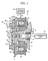
- FIG. 1 shows a part of a compressor according to a first embodiment.
- the compressor is contained in a regrigeration device using CO 2 as refrigerant. More specifically, the refrigeration plat is included in a vehicle airconditioning system.
- FIG. 1 only shows a part of the housing 2.
- a rotary shaft 4 which is rotatably supported through bearings (not shown) with respect to the housing 2.
- a mechanical seal 6 serving as a shaft sealing unit is also located in the housing 2.
- the mechanical seal 6 keeps an airtight condition between the housing 2 and the rotary shaft 4.
- the mechanical seal 6 includes a sheet 7a fixed to the housing 2 and a seal ring 7b fitted to the rotary shaft 4 and pressed against the sheet 7a.
- the sheet 7a and the seal ring 7b have annular seal faces 8a and 8b that are in close contact.
- lip seals may be utilized as the shaft sealing unit.
- the lip seal is placed between the rotary shaft 4 and the housing 2 and has a cylindrical seal face.
- the rotary shaft 4 has one end portion 10 protruding from the housing 2 and the other end portion (not shown) that is positioned within the housing 2.
- the other end portion of the rotary shaft 4 is connected to a compression unit 12.
- the compression unit 12 is accommodated in the housing 2 and is driven by the rotary shaft 4.
- the compression unit 12 is, for example, either one of a swashplate compression unit including a piston that makes a reciprocating motion according to the rotary shaft 4 and a scroll compression unit including a movable scroll that makes an orbiting motion according to the rotary shaft 4.
- the compression unit 12 When driven, the compression unit 12 repeatedly performs a sequence of processes, starting with suction of CO 2 refrigerant, followed by compression and discharge of the CO 2 refrigerant, thereby circulating the CO 2 refrigerant through a refrigerant circuit of the regrigeration device.
- the one end portion 10 of the rotary shaft 4 is connected to a driving source 15 through a power transmission path 13.
- the driving source 15 is either an engine or motor of a vehicle.
- An electromagnetic clutch 14 serving as a power transmission device is interposed in the power transmission path 13.
- the electromagnetic clutch 14 is mounted on the compressor.
- the electromagnetic clutch 14 includes a rotor 16.
- the rotor 16 is rotatably supported by an outer circumferential surface of the housing 2 through a bearing 18.
- the rotor 16 has an end face 16a located on the side of the one end portion 10 of the rotary shaft 4, and is also formed as a driving pulley 20.
- the driving pulley 20 is connected to the power transmission path 13, more specifically, to an output pulley (not shown) of the driving source 15 through an endless driving belt (not shown). Accordingly, when a driving force is transmitted from the driving source 15 to the driving pulley 20, the driving pulley 20, or the rotor 16, is rotated in one direction.
- the electromagnetic clutch 14 has a clutch mechanism 24.
- the clutch mechanism 24 will be described below in detail.
- the clutch mechanism 24 includes an electromagnetic solenoid 22 located in the inside of the rotor 16.
- the electromagnetic solenoid 22 is fixed onto the outer circumferential surface of the housing 2 through a ring-shaped bracket 21.
- the clutch mechanism 24 further includes a first rotation member, that is, a disc-shaped armature 26.
- the armature 26 is disposed opposed to the one end face 16a of the rotor 16.
- the armature 26 has a circular opening 27 in the center thereof. As illustrated in FIG. 1 , when the electromagnetic clutch 14 is in a resting state, there is secured a given gap amount L between the armature 26 and the one end face 16a of the rotor 16.
- the armature 26 is coupled to an inner support 31 serving as a second rotation member through a spring unit 28.
- the spring unit 28 is set in an outer surface of the armature 26, that is, in an opposite face to the rotor 16.
- the spring unit 28 has an outer ring 30 and a spring element 32 that is interfitted in the outer ring 30.
- the spring element 32 is made of synthetic rubber and formed to have a ring-like shape. As is apparent from FIG. 1 , the spring element 32 integrally has a plurality of projections 32a in an inner circumference thereof. The projections 32a are arranged at regular intervals in a circumferential direction of the spring unit 28 and are in contact with the armature 26.
- the outer ring 30 is made of metal and integrally has three lugs 33 in an outer circumference thereof.
- the lugs 33 are arranged at regular intervals in a circumferential direction of the outer ring 30, and fixed on the armature 26 by using rivets 34.
- the spring unit 28 is accordingly coupled to the armature 26 in an outer circumferential portion thereof.
- FIG. 1 shows only one of the lugs 33 and one of the rivets 34.
- the inner support 31 is made of metal and has a disclike shape.
- the inner support 31 has a rim 31a in an outer circumference thereof.
- the rim 31a bears the spring element 32 in consort with the outer ring 30 so that the spring element 32 is sandwiched between the rim 31a and the outer ring 30, and is fixed on the spring element 32.
- the inner support 31 is coupled to the armature 26 serving as the first rotation member with the spring unit 28 intervening therebetween.
- the inner support 31 is fitted to a hub 48 in an inner circumferential portion thereof.
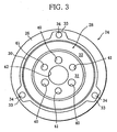
- the hub 48 is mounted on the one end portion 10 of the rotary shaft 4. More concretely, as illustrated in FIGS. 2 and 3 , the inner support 31 has a circular opening 42 positioned in the center thereof and three bores 40 arranged outside the opening 42. The bores 40 are distributed on the same circle and arranged at regular intervals in a circumferential direction of the inner support 31.
- the inner support 31 further has three bores 41. The bores 41 are arranged in the circumferential direction of the inner support 31 so that each of the bores 41 is located between two adjacent bores 40.
- opening 42 and the bores 40 and 41 of the inner support 31 are disposed within an area with a smaller diameter than that of the opening 27 of the armature 26.
- the hub 48 has a shape of a stepped hollowcylinder.
- Formed in the hub 48 is an axial bore 49.
- the axial bore 49 extends along an axis of the hub 48 and passes through the hub 48.
- the axial bore 49 has a female spline 50f in the center thereof, and one end portion of the axial bore 49, which is located on the side of the inner support 31, is formed as a circular recessed area 51.
- the recessed area 51 has a larger internal diameter than that of the axial bore 49.
- a male spline 50m is formed on the one end portion 10 of the rotary shaft 4.
- the one end portion 10 has a male thread 10a that is formed in an outer circumferential surface thereof so as to extend from the male spline 50m to a tip end of the one end portion 10.
- the male spline 50m is engaged with the female spline 50f of the axial bore 49. This allows the hub 48 to rotate integrally with the rotary shaft 4, relative to the circumferential direction of the rotary shaft 4.
- the male thread 10a of the rotary shaft 4 is located within the recessed area of the hub 48. As illustrated in FIG. 1 , a nut 11 is screwed on the male thread 10a, thereby interlocking the hub 48 to the rotary shaft 4.
- the hub 48 has a flange 52 located in the one end side of the axial bore 49.
- the flange 52 is protruding outward in a radial direction of the hub 48.
- the flange 52 has an external diameter that is slightly smaller than the internal diameter of the opening 27 of the armature 26.
- Formed in the flange 52 are three screw holes 56, which are distributed on the same circle and arranged at regular intervals in a circumferential direction of the hub 48.
- the distribution circle of the screw holes 56 has the same diameter as the distribution circle of the bores 40 of the inner support 31. Therefore, as is apparent from FIG. 2 , the screw holes 56 can be positioned coaxially with the respective bores 40.
- three circular recesses 53 are formed in the flange 52.
- the circular recesses 53 correspond to the respective bores 41 of the inner support 31.
- the hub 48 further includes an annular projection 58 in one end face thereof which is located on the flange 52 side.
- the annular projection 58 has an external diameter slightly smaller than an internal diameter of the opening 42 of the inner support 31. Therefore, as is evident from FIG. 1 , the inner support 31 is fitted on the hub 48 in a state where the annular projection 58 is inserted in the opening 42. At this moment, the bores 40 of the inner support 31 coincide with the respective screw holes 56.
- the annular projection 58 has an internal diameter identical to an internal diameter of the recessed area 51.
- a shim 62 is sandwiched between the inner support 31 and the flange 52 of the hub 48.
- the shim 62 is used to secure the gap L.
- the inner support 31 and the flange 52 of the hub 48 have flat receiving faces 38 and 54, respectively, with respect to the shim 62.
- the shim 62 is formed into a disc and has substantially the same external diameter as the flange 52 of the hub 48. Both sides of the shim 62 are formed as flat contact faces 64a and 64b to be in close contact with the receiving faces 38 and 54, respectively.
- the shim 62 has an opening 66 located in the center thereof, three bores 68 arranged outside of the opening 66, and three bores 65 each arranged between the respective two adjacent bores 68.
- the opening 66 is allowed to coincide with the opening 42 of the inner support 31, and the bores 68 and 65 with the respective bores 40 and 41 of the inner support 31.
- the hub 48 is firstly spline-engaged with the one end portion 10 of the rotary shaft 4, and the hub 48 is fixed onto the rotary shaft 4 with the nut 11.
- the shim 62 is mounted on the annular projection 58 of the hub 48, the armature 26 and the inner support 31 provided with the spring unit 28 are fixed to the hub 48.
- the shim 62 is sandwiched between the inner support 31 and the flange 52 of the hub 48, and the gap L is created due to thickness of the shim 62.
- the electromagnetic solenoid 22 when the electromagnetic solenoid 22 is supplied with electric power, the electromagnetic solenoid 22 attracts the armature 26 while elastically deforming the spring element 32 of the spring unit 28, thereby frictionally engaging the armature 26 and the rotor 16 with each other. At this point, the rotation of the rotor 16 is transmitted to the rotary shaft 4 through the armature 26, the spring unit 28, the inner support 31, and the hub 48. The rotary shaft 4 then rotates together with the rotor 16 and drives the compression unit 12.
- the spring element 32 of the spring unit 28 detaches the armature 26 from the rotor 16 by using a restoring force thereof, thereby securing the gap L between the armature 26 and the rotor 16. In such a resting state of the electromagnetic clutch 14, accordingly, the rotation of the rotor 16 is not transmitted to the rotary shaft 4, which stops the driving of the compression unit 12.
- the shim 62 that secures the given gap L between the rotor 16 and the armature 26 when the electromagnetic clutch 14 is in the resting state, is sandwiched between the inner support 31 of the clutch mechanism 24 and the hub 48. Consequently, the rotary shaft 4 does not need a stepped face formed by reducing the diameter of the rotary shaft 4 to sandwich a shim between the rotary shaft 4 and the hub 48.
- the rotary shaft 4 can be reduced in diameter regardless of the shim 62, and the sealing performance of the mechanical seal 6 is stably assured for a long term.
- the shim 62 includes the large contact faces 64a and 64b with respect to the inner support 31 and the hub 48, surface pressure that is applied to the shim 62 is drastically reduced. This also decreases abrasion of the shim 62 which is caused by vibrations of the armature 26. The shim 62 then stably retains the gap L for a long period and assures a stable operation of the electromagnetic clutch 14.
- compressors according to second and third embodiments will be described below. Throughout the description about the compressors according to the second and third embodiments, members and portions identical to those of the compressor of the first embodiment will be referred by identical reference marks, and descriptions thereof will be omitted. Differences from the first embodiment will be explained below.
- the compressor according to the second embodiment has a torque limiter 14A instead of the electromagnetic clutch 14.
- the torque limiter 14A includes a clutch mechanism 24A that connects the rotor 16 and the rotary shaft 4 to each other.
- the clutch mechanism 24A has a spring unit 28A as a first rotation member.
- the lugs 33 of the spring unit 28A instead of the rivets 34 of the first embodiment, are fixed to the rotor 16 with bolts 34A.
- the spring unit 28A includes an inner ring 78 made of metal.
- a spring element 32 is sandwiched between the inner ring 78 and the outer ring 30.
- the spring element 32 is interfitted both in the outer ring 30 and the inner ring 78.
- the inner support 31A is disposed in the inside of the inner ring 78.
- the inner support 31A is not connected to either the inner ring 78 or the spring element 32, thereby being in a state detached from both the inner ring 78 and the spring element 32.
- a boss 35 is formed in the center of an outer surface of the inner support 31A.
- the boss 35 has a male screw 37 in an outer circumferential surface thereof.
- a circular recessed area 39 is formed in an inner surface of the inner support 31A.
- the recessed area 39 has an internal diameter and depth that are identical to an external diameter and thickness of a flange 52A of the hub 48A. Therefore, as is evident from FIG. 6 , the inner support 31A is fitted to the hub 48A in a state receiving the flange 52A of the hub 48A in the recessed area 39, and is fastened to the hub 48A with a plurality of connecting bolts 46.
- An annular projection 58A of the hub 48A extends in an axial direction of the hub 48A and is interfitted in an opening 42 of the boss 35.
- a pressure plate 72 Disposed between the boss 35 and the spring element 32 is a pressure plate 72.
- the pressure plate 72 is fastened to the boss 35 with a washer 46B and a nut 46A intervening therebetween, and the nut 46A is screwed on the male thread 37 of the boss 35.
- the pressure plate 72 defines an annular accommodation chamber 73 in cooperation with the boss 35, the spring element 32, the inner ring 78 and the inner support 31A.
- the accommodation chamber 73 is surrounded by the above-mentioned members 31A, 32, 35 and 78.
- a plurality of balls 70 are contained in the accommodation chamber 73.
- the balls 70 have outer surfaces that have been subjected to hardening treatment, and are arranged at regular intervals in a circumferential direction of the inner support 31A.
- the pressure plate 72 has a tapered face 72a in an inner surface on the side of the accommodation chamber 73.
- the tapered face 72a gradually reduces width of the accommodation chamber 73 along an axial direction of the boss 35 toward the boss 35.
- the inner support 31A has an annular projection 76 and an annular clearance groove 74 in the inner surface on the side of the accommodation chamber 73.
- the clearance groove 74 is located more inside than the annular projection 76, as viewed in a radial direction of the inner support 31A.
- the balls 70 are held between the tapered face 72a of the pressure plate 72 and the annular projection 76 of the inner support 31A.
- the balls 70 are also in a state pressed against the inner ring 78 by an urging ring 80 such as a spiral spring.
- the urging ring 80 is contained in the accommodation chamber 73.
- a bottom face of the recessed area 39 in the inner support 31A is formed as the flat receiving face 38.
- a shim 62A is sandwiched between the receiving face 38 and a receiving face 54 of the hub 48A. The shim 62A adjusts the position of the inner support 31A relative to the axial direction of the rotary shaft 4, secures the given gap L between the spring element 32 and the rotor 16, and prevents the spring element 32 from contacting the rotor 16.
- the shim 62A provides the compressor with similar advantages as with the shim 62 of the first embodiment.
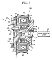
- FIGS. 7 to 9 show the compressor according to the third embodiment.
- the compressor of the third embodiment has an electromagnetic clutch 14B.
- the electromagnetic clutch 14B includes, instead of the connecting bolts 46 of the first embodiment, a plurality of hollow pins 46B for fastening an inner support 31B to a hub 48B. Therefore, as illustrated in FIG. 8 , the inner support 31B has bores 44 instead of the bores 40 of the first embodiment, whereas the hub 48B has through holes 60 instead of the screw holes 56 of the first embodiment.
- a shim 62B has three bores 68B instead of the bores 68 of the first embodiment.
- the hollow pins 46B are inserted into the respective through holes 60 of the hub 48B through the bores 44 of the inner support 31B and the bores 68B of the shim 62B, thereby fitting the inner support 31B to the hub 48B.
- the shim 62B of the third embodiment also exhibits similar advantages as with the shim 62 of the first embodiment.
- the connection of the inner support 31B and the hub 48B is achieved by insertion of the hollow pins 46B. Therefore, the connection is easy, and also the radial positioning of the inner support 31B in relation to the hub 48B can be carried out with accuracy. Consequently, the compressor is greatly improved in productivity.
- the hollow pins 46B are suitable for power transmission from the inner support 31B to the hub 48B. Load, especially a shearing force, applied to the hollow pins 46B is reduced.
- FIG. 10 relates to connection of an inner support 31C and a hub 48C and shows a modification example thereof.
- the inner support 31C integrally includes protruding portions 82, and the hub 48C has recess portions 84 in which the protruding portions 82 are inserted, respectively. Therefore, the inner support 31C and the hub 48C are connected to each other by fitting the protruding portions 82 into the recess portions 84. In this process, the protruding portions 82 penetrate bores of a shim 62C.
- the protruding portions 82 and the recess portions 84 form a faucet joint.
- a faucet joint can include the protruding portions 82 formed in the hub 48C and the recess portions 84 formed in the inner support 31C.
- the invention is not limited to the compressors according to the first to fourth embodiments.
- the torque limiter may be a notch type including a break-away notch, instead of the ball type shown in FIG. 6 .
- a notch-type torque limiter is broken at a notch when overload is applied to the notch, and breaks power transmission from a rotor to a rotary shaft.
Landscapes
- Engineering & Computer Science (AREA)
- General Engineering & Computer Science (AREA)
- Mechanical Engineering (AREA)
- Manufacturing & Machinery (AREA)
- Physics & Mathematics (AREA)
- Electromagnetism (AREA)
- Compressors, Vaccum Pumps And Other Relevant Systems (AREA)
- Compressor (AREA)
- Applications Or Details Of Rotary Compressors (AREA)
Claims (6)
- Kompressor, aufweisend:ein Gehäuse (2);eine drehbar in dem Gehäuse (2) gelagerte Rotationswelle (4), wobei die Rotationswelle (4) ein Ende hat, das von dem Gehäuse (2) vorsteht;eine in dem Gehäuse (2) enthaltene Kompressionseinheit (12), wobei die Kompressionseinheit (12), beginnend mit einem Ansaugen eines Arbeitsfluids, gefolgt on einem Komprimieren und einem Ausstoßen des Arbeitsfluids, eine Folge von Prozessen ausführt, wenn sie durch die Rotationswelle (4) angetrieben wird;eine zwischen dem Gehäuse (2) und der Rotationswelle (4) angeordnete Wellendichteinheit (6) zum luftdichten Abdichten des Inneren des Gehäuses (2); undeine Leistungsübertragungsvorrichtung zum Übertragen einer Antriebskraft von einer Antriebsquelle (15) auf das eine Ende der Rotationswelle (4), wobeidie Leistungsübertragungsvorrichtung enthält:einen durch eine äußere Fläche des Gehäuses (2) durch ein Lager (18) drehbar gelagerten Rotor (16) zum Aufnehmen der Antriebskraft von der Antriebsquelle (15);eine an das eine Ende der Rotationswelle (4) gekoppelte Nabe (48), um mit der Rotationswelle (4) zu rotieren; undeinen Kupplungsmechanismus (24) zum Steuern einer Übertragung einer Rotationskraft von dem Rotor (16) auf die Nabe (48), wobei der Kupplungsmechanismus (24) ein erstes bezüglich einer axialen Richtung der Rotationswelle (4) zu dem Rotor (16) benachbart angeordnetes Rotationsbauteil (26) zum Aufnehmen der Rotationskraft des Rotors (16) und ein zweites bezüglich der axialen Richtung zu der Nabe (48) benachbart angeordnetes Rotationsbauteil (31) enthält, wobei das zweite Rotationsbauteil (31) an die Nabe (48) gekoppelt ist und die Rotationskraft des ersten Rotationsbauteils (26) aufnimmt,dadurch gekennzeichnet, dassder Kupplungsmechanismus (24) fernerein Befestigungsbauteil (46, 46B, 82), das das zweite Rotationsbauteil (31) und die Nabe (48) befestigt, undeine zwischen das zweite Rotationsbauteil (31) und die Nabe (48) eingefügte Scheibe (62, 62A) aufweist, wobei die Scheibe (62, 62A) in der axialen Richtung eine Position des ersten Rotationsbauteils (26) bezüglich des Rotors (16) bestimmt.
- Kompressor gemäß Anspruch 1, wobei:der Kupplungsmechanismus eine elektromagnetische Kupplung (14) ist, die eine innerhalb des Rotors (16) angeordnete elektromagnetische Spule (22) enthält, wobei:das erste Rotationsbauteil (26) des Kupplungsmechanismus (24)einen Anker (26) zum Aufnehmen der Rotationskraft des Rotors (16), wenn die elektromagnetische Spule (22) in einem betriebenen Zustand ist und der Anker (26) durch die elektromagnetische Spule (22) zu dem Rotor (16) angezogen wird, undein Federelement (32) enthält, das den Anker (26) drängt, um in der axialen Richtung einen Spalt (L) zwischen dem Rotor (16) und dem Anker (26) sicherzustellen, wenn die elektromagnetische Spule in einem Ruhezustand ist, wobei das Federelement (32) aus einem synthetischen Gummi hergestellt ist, unddie Scheibe (62) eine Größe des Spalts (L) durch das Federelement (32) bestimmt.
- Kompressor gemäß Anspruch 1, wobei
der Kupplungsmechanismus ein Drehmomentbegrenzer (14A) zum Unterbrechen einer Übertragung der Rotationskraft von dem Rotor (16) zu der Rotationswelle (4), wenn die Rotationswelle (4) in einen arretierten Zustand kommt, ist,
das erste Rotationsbauteil des Drehmomentbegrenzers (14A) ein mit dem Rotor (16) verbundenes Federelement (32) ist, wobei das Federelement (32) aus einem synthetischen Gummi hergestellt ist, und
die Scheibe (62A) in der axialen Richtung einen Spalt (L) zwischen dem Rotor (16) und dem Federelement (32) sicherstellt. - Kompressor gemäß einem der Ansprüche 1 bis 3, wobei:der Kupplungsmechanismus (24) ferner das in einem von beiden, in dem zweiten Rotationsbauteil (31) oder in der Nabe (48), angeordnete Befestigungsbauteil (46, 46B, 82) und ein in dem anderen von dem zweiten Rotationsbauteil (31) und der Nabe (48) angeordnetes Aufnahmebauteil (56, 60, 84) zum Aufnehmen des Befestigungsbauteils enthält, um das Befestigungsbauteil aufzunehmen, um das zweite Rotationsbauteil (31) und die Nabe (48) aneinander zu koppeln, unddie Scheibe (62A) eine Bohrung (68) hat, in die das Befestigungsbauteil (46, 46B, 82) eingebracht ist.
- Kompressor gemäß Anspruch 4, wobei:das Befestigungsbauteil eines von einer Schraube (46), einem Stift (46B) und einem vorstehenden Abschnitt (82), der einstückig in einem oder dem anderen von dem zweiten Rotationsbauteil (31C) und der Nabe (48C) gebildet ist, ist.
- Kompressor gemäß einem der Ansprüche 1 bis 5, wobei:das Arbeitsfluid CO2-Gas enthält.
Applications Claiming Priority (2)
| Application Number | Priority Date | Filing Date | Title |
|---|---|---|---|
| JP2005295022A JP4713293B2 (ja) | 2005-10-07 | 2005-10-07 | 圧縮機 |
| PCT/JP2006/319989 WO2007043444A1 (ja) | 2005-10-07 | 2006-10-05 | 圧縮機及び動力伝達装置 |
Publications (3)
| Publication Number | Publication Date |
|---|---|
| EP1933032A1 EP1933032A1 (de) | 2008-06-18 |
| EP1933032A4 EP1933032A4 (de) | 2010-11-10 |
| EP1933032B1 true EP1933032B1 (de) | 2013-08-21 |
Family
ID=37942687
Family Applications (1)
| Application Number | Title | Priority Date | Filing Date |
|---|---|---|---|
| EP06821824.7A Not-in-force EP1933032B1 (de) | 2005-10-07 | 2006-10-05 | Kompressor und leistungsübertragungsvorrichtung |
Country Status (5)
| Country | Link |
|---|---|
| US (1) | US20090047162A1 (de) |
| EP (1) | EP1933032B1 (de) |
| JP (1) | JP4713293B2 (de) |
| CN (1) | CN101155991B (de) |
| WO (1) | WO2007043444A1 (de) |
Families Citing this family (18)
| Publication number | Priority date | Publication date | Assignee | Title |
|---|---|---|---|---|
| US9518815B2 (en) * | 2008-08-06 | 2016-12-13 | Haas Automation, Inc. | Rotary position encoder for rotatable shafts |
| US8813334B2 (en) | 2008-08-07 | 2014-08-26 | Schaeffler Technologies Gmbh & Co. Kg | Double clutch |
| US9482286B2 (en) | 2011-04-13 | 2016-11-01 | Borgwarner Inc. | Fail-safe dry friction clutch for a vehicle accessory |
| US9453571B2 (en) * | 2012-12-24 | 2016-09-27 | Borgwarner Inc. | Metal pulley with non-magnetically susceptible insert |
| US9458897B2 (en) | 2012-12-24 | 2016-10-04 | Borgwarner Inc. | Accessory drive with friction clutch |
| US9863486B2 (en) | 2012-12-24 | 2018-01-09 | Borgwarner Inc. | Driven accessory |
| US9447826B2 (en) | 2012-12-24 | 2016-09-20 | Borgwarner Inc. | Friction clutch for driven accessory |
| DE202013002597U1 (de) * | 2013-03-18 | 2013-03-26 | Erwin A. Lang Gmbh & Co. Kg | Elektromagnetische Kupplungsvorrichtung |
| WO2014182350A1 (en) * | 2013-05-08 | 2014-11-13 | Eaton Corporation | Supercharger torsional compliance and damping features |
| JP6248773B2 (ja) * | 2014-04-17 | 2017-12-20 | 株式会社デンソー | 動力伝達装置 |
| US9790997B2 (en) * | 2014-09-17 | 2017-10-17 | Electro-Motive Diesel, Inc. | Assembly for preventing abuse of a pump mounted to a driver equipment |
| JP6597746B2 (ja) * | 2016-11-10 | 2019-10-30 | 株式会社デンソー | 動力伝達装置 |
| US10724592B2 (en) | 2017-04-20 | 2020-07-28 | Consolidated Metco, Inc. | High friction insulator |
| KR102590950B1 (ko) * | 2017-06-28 | 2023-10-19 | 한온시스템 주식회사 | 클러치 및 이를 포함하는 압축기 |
| JP6747399B2 (ja) * | 2017-07-28 | 2020-08-26 | 株式会社デンソー | 動力伝達装置 |
| CN109253174B (zh) * | 2018-12-06 | 2023-06-30 | 上汽红岩车桥(重庆)有限公司 | 重型汽车传动结构 |
| US12571441B2 (en) | 2020-05-05 | 2026-03-10 | Consolidated Metco, Inc. | Commercial vehicle brake rotor |
| US20250313085A1 (en) * | 2024-04-05 | 2025-10-09 | Muncie Power Products, Inc. | Adjustable shim |
Family Cites Families (14)
| Publication number | Priority date | Publication date | Assignee | Title |
|---|---|---|---|---|
| US3024963A (en) * | 1955-03-23 | 1962-03-13 | Gen Motors Corp | Refrigerating apparatus |
| JPH0266324A (ja) * | 1988-08-31 | 1990-03-06 | Hitachi Ltd | 電磁クラッチ |
| JPH0258120U (de) * | 1988-10-24 | 1990-04-26 | ||
| JPH04339189A (ja) * | 1991-05-15 | 1992-11-26 | Sanden Corp | スクロール型流体装置 |
| JPH0874885A (ja) * | 1994-09-07 | 1996-03-19 | Sanden Corp | 電磁クラッチ |
| US5683299A (en) * | 1994-09-14 | 1997-11-04 | Nippondenso Co., Ltd. | Device for transmitting rotational power |
| JPH08135752A (ja) * | 1994-09-14 | 1996-05-31 | Nippondenso Co Ltd | 動力伝達装置 |
| JP2907382B2 (ja) * | 1995-01-30 | 1999-06-21 | 小倉クラッチ株式会社 | 電磁連結装置 |
| JP3480094B2 (ja) * | 1995-02-06 | 2003-12-15 | 株式会社豊田自動織機 | クラッチレス圧縮機における動力遮断機構 |
| JPH10115333A (ja) * | 1996-10-11 | 1998-05-06 | Zexel Corp | 電磁クラッチ |
| JP2001173682A (ja) * | 1999-12-15 | 2001-06-26 | Mitsubishi Heavy Ind Ltd | 圧縮機の電磁クラッチ構造 |
| EP1164289A3 (de) * | 2000-06-13 | 2003-09-24 | Kabushiki Kaisha Toyota Jidoshokki | Taumelscheibenkompressor |
| JP4888801B2 (ja) * | 2001-05-22 | 2012-02-29 | 株式会社ヴァレオジャパン | 電磁クラッチ |
| JP3984465B2 (ja) * | 2001-12-04 | 2007-10-03 | サンデン株式会社 | 動力伝達機構 |
-
2005
- 2005-10-07 JP JP2005295022A patent/JP4713293B2/ja not_active Expired - Fee Related
-
2006
- 2006-10-05 EP EP06821824.7A patent/EP1933032B1/de not_active Not-in-force
- 2006-10-05 WO PCT/JP2006/319989 patent/WO2007043444A1/ja not_active Ceased
- 2006-10-05 US US11/886,896 patent/US20090047162A1/en not_active Abandoned
- 2006-10-05 CN CN2006800093809A patent/CN101155991B/zh not_active Expired - Fee Related
Also Published As
| Publication number | Publication date |
|---|---|
| JP4713293B2 (ja) | 2011-06-29 |
| JP2007100675A (ja) | 2007-04-19 |
| US20090047162A1 (en) | 2009-02-19 |
| WO2007043444A1 (ja) | 2007-04-19 |
| CN101155991B (zh) | 2010-06-09 |
| EP1933032A1 (de) | 2008-06-18 |
| EP1933032A4 (de) | 2010-11-10 |
| CN101155991A (zh) | 2008-04-02 |
Similar Documents
| Publication | Publication Date | Title |
|---|---|---|
| EP1933032B1 (de) | Kompressor und leistungsübertragungsvorrichtung | |
| US5683299A (en) | Device for transmitting rotational power | |
| EP1887224B1 (de) | Leistungsübertragungsmechanismus | |
| US6494799B1 (en) | Power transmission device | |
| JPH094564A (ja) | 圧縮機における動力伝達構造 | |
| US20100307884A1 (en) | Electromagnetic clutch | |
| EP0867631A1 (de) | Drehmomentbegrenzer | |
| US20010025761A1 (en) | Torque limiting mechanism | |
| JP2001280364A (ja) | 動力伝達機構 | |
| US20120251347A1 (en) | Compressor with transmission | |
| US5751202A (en) | Electromagnetic coupling device | |
| JP2001153152A (ja) | 動力伝達機構 | |
| US20060089224A1 (en) | Power transmission device | |
| US10851842B2 (en) | Power transmission device | |
| JPH10318280A (ja) | 動力伝達機構 | |
| EP1529977A1 (de) | Kraftübertragungsmechanismus und Verfahren zum Zusammensetzen eines solchen Mechanismus | |
| JP2000170870A (ja) | 動力伝達機構 | |
| JPH10318283A (ja) | 動力伝達機構及び動力伝達機構を用いた圧縮機 | |
| JPH11108146A (ja) | 動力伝達装置 | |
| KR20240050689A (ko) | 압축기 및 이에 포함되는 풀리 제조 방법 | |
| KR101409147B1 (ko) | 클러치리스 압축기의 동력전달장치 | |
| JP5407827B2 (ja) | 圧縮機 | |
| CN113417949B (zh) | 一种气动离合器 | |
| JPH10318276A (ja) | 動力伝達機構 | |
| JP2000352428A (ja) | 動力伝達機構及び圧縮機 |
Legal Events
| Date | Code | Title | Description |
|---|---|---|---|
| PUAI | Public reference made under article 153(3) epc to a published international application that has entered the european phase |
Free format text: ORIGINAL CODE: 0009012 |
|
| 17P | Request for examination filed |
Effective date: 20070919 |
|
| AK | Designated contracting states |
Kind code of ref document: A1 Designated state(s): DE FR |
|
| DAX | Request for extension of the european patent (deleted) | ||
| RBV | Designated contracting states (corrected) |
Designated state(s): DE FR |
|
| A4 | Supplementary search report drawn up and despatched |
Effective date: 20101008 |
|
| 17Q | First examination report despatched |
Effective date: 20110622 |
|
| GRAP | Despatch of communication of intention to grant a patent |
Free format text: ORIGINAL CODE: EPIDOSNIGR1 |
|
| GRAS | Grant fee paid |
Free format text: ORIGINAL CODE: EPIDOSNIGR3 |
|
| GRAA | (expected) grant |
Free format text: ORIGINAL CODE: 0009210 |
|
| AK | Designated contracting states |
Kind code of ref document: B1 Designated state(s): DE FR |
|
| REG | Reference to a national code |
Ref country code: DE Ref legal event code: R096 Ref document number: 602006038030 Country of ref document: DE Effective date: 20131017 |
|
| PGFP | Annual fee paid to national office [announced via postgrant information from national office to epo] |
Ref country code: FR Payment date: 20131022 Year of fee payment: 8 |
|
| PLBE | No opposition filed within time limit |
Free format text: ORIGINAL CODE: 0009261 |
|
| STAA | Information on the status of an ep patent application or granted ep patent |
Free format text: STATUS: NO OPPOSITION FILED WITHIN TIME LIMIT |
|
| 26N | No opposition filed |
Effective date: 20140522 |
|
| REG | Reference to a national code |
Ref country code: DE Ref legal event code: R097 Ref document number: 602006038030 Country of ref document: DE Effective date: 20140522 |
|
| REG | Reference to a national code |
Ref country code: FR Ref legal event code: ST Effective date: 20150630 |
|
| PG25 | Lapsed in a contracting state [announced via postgrant information from national office to epo] |
Ref country code: FR Free format text: LAPSE BECAUSE OF NON-PAYMENT OF DUE FEES Effective date: 20141031 |
|
| REG | Reference to a national code |
Ref country code: DE Ref legal event code: R082 Ref document number: 602006038030 Country of ref document: DE Representative=s name: PRUEFER & PARTNER MBB PATENTANWAELTE RECHTSANW, DE Ref country code: DE Ref legal event code: R081 Ref document number: 602006038030 Country of ref document: DE Owner name: SANDEN HOLDINGS CORPORATION, LSESAKI-SHI, JP Free format text: FORMER OWNER: SANDEN CORPORATION, ISESAKI-SHI, GUNMA-KEN, JP |
|
| PGFP | Annual fee paid to national office [announced via postgrant information from national office to epo] |
Ref country code: DE Payment date: 20161020 Year of fee payment: 11 |
|
| REG | Reference to a national code |
Ref country code: DE Ref legal event code: R119 Ref document number: 602006038030 Country of ref document: DE |
|
| PG25 | Lapsed in a contracting state [announced via postgrant information from national office to epo] |
Ref country code: DE Free format text: LAPSE BECAUSE OF NON-PAYMENT OF DUE FEES Effective date: 20180501 |