EP2012198A1 - Verfahren und geräte zum verarbeiten eines optischen aufzeichnungsmediums und optische aufzeichnungs-/wiedergabevorrichtung - Google Patents
Verfahren und geräte zum verarbeiten eines optischen aufzeichnungsmediums und optische aufzeichnungs-/wiedergabevorrichtung Download PDFInfo
- Publication number
- EP2012198A1 EP2012198A1 EP06834917A EP06834917A EP2012198A1 EP 2012198 A1 EP2012198 A1 EP 2012198A1 EP 06834917 A EP06834917 A EP 06834917A EP 06834917 A EP06834917 A EP 06834917A EP 2012198 A1 EP2012198 A1 EP 2012198A1
- Authority
- EP
- European Patent Office
- Prior art keywords
- optical recording
- recording medium
- light
- layer
- bis
- Prior art date
- Legal status (The legal status is an assumption and is not a legal conclusion. Google has not performed a legal analysis and makes no representation as to the accuracy of the status listed.)
- Granted
Links
Images



Classifications
-
- G—PHYSICS
- G11—INFORMATION STORAGE
- G11B—INFORMATION STORAGE BASED ON RELATIVE MOVEMENT BETWEEN RECORD CARRIER AND TRANSDUCER
- G11B7/00—Recording or reproducing by optical means, e.g. recording using a thermal beam of optical radiation by modifying optical properties or the physical structure, reproducing using an optical beam at lower power by sensing optical properties; Record carriers therefor
- G11B7/007—Arrangement of the information on the record carrier, e.g. form of tracks, actual track shape, e.g. wobbled, or cross-section, e.g. v-shaped; Sequential information structures, e.g. sectoring or header formats within a track
- G11B7/00772—Arrangement of the information on the record carrier, e.g. form of tracks, actual track shape, e.g. wobbled, or cross-section, e.g. v-shaped; Sequential information structures, e.g. sectoring or header formats within a track on record carriers storing information in the form of optical interference patterns, e.g. holograms
- G11B7/00781—Auxiliary information, e.g. index marks, address marks, pre-pits, gray codes
-
- G—PHYSICS
- G03—PHOTOGRAPHY; CINEMATOGRAPHY; ANALOGOUS TECHNIQUES USING WAVES OTHER THAN OPTICAL WAVES; ELECTROGRAPHY; HOLOGRAPHY
- G03H—HOLOGRAPHIC PROCESSES OR APPARATUS
- G03H1/00—Holographic processes or apparatus using light, infrared or ultraviolet waves for obtaining holograms or for obtaining an image from them; Details peculiar thereto
- G03H1/04—Processes or apparatus for producing holograms
- G03H1/18—Particular processing of hologram record carriers, e.g. for obtaining blazed holograms
-
- G—PHYSICS
- G11—INFORMATION STORAGE
- G11B—INFORMATION STORAGE BASED ON RELATIVE MOVEMENT BETWEEN RECORD CARRIER AND TRANSDUCER
- G11B7/00—Recording or reproducing by optical means, e.g. recording using a thermal beam of optical radiation by modifying optical properties or the physical structure, reproducing using an optical beam at lower power by sensing optical properties; Record carriers therefor
- G11B7/004—Recording, reproducing or erasing methods; Read, write or erase circuits therefor
- G11B7/0065—Recording, reproducing or erasing by using optical interference patterns, e.g. holograms
-
- G—PHYSICS
- G11—INFORMATION STORAGE
- G11B—INFORMATION STORAGE BASED ON RELATIVE MOVEMENT BETWEEN RECORD CARRIER AND TRANSDUCER
- G11B7/00—Recording or reproducing by optical means, e.g. recording using a thermal beam of optical radiation by modifying optical properties or the physical structure, reproducing using an optical beam at lower power by sensing optical properties; Record carriers therefor
- G11B7/12—Heads, e.g. forming of the optical beam spot or modulation of the optical beam
- G11B7/125—Optical beam sources therefor, e.g. laser control circuitry specially adapted for optical storage devices; Modulators, e.g. means for controlling the size or intensity of optical spots or optical traces
- G11B7/127—Lasers; Multiple laser arrays
- G11B7/1275—Two or more lasers having different wavelengths
-
- G—PHYSICS
- G11—INFORMATION STORAGE
- G11B—INFORMATION STORAGE BASED ON RELATIVE MOVEMENT BETWEEN RECORD CARRIER AND TRANSDUCER
- G11B7/00—Recording or reproducing by optical means, e.g. recording using a thermal beam of optical radiation by modifying optical properties or the physical structure, reproducing using an optical beam at lower power by sensing optical properties; Record carriers therefor
- G11B7/12—Heads, e.g. forming of the optical beam spot or modulation of the optical beam
- G11B7/135—Means for guiding the beam from the source to the record carrier or from the record carrier to the detector
- G11B7/1392—Means for controlling the beam wavefront, e.g. for correction of aberration
-
- G—PHYSICS
- G11—INFORMATION STORAGE
- G11B—INFORMATION STORAGE BASED ON RELATIVE MOVEMENT BETWEEN RECORD CARRIER AND TRANSDUCER
- G11B7/00—Recording or reproducing by optical means, e.g. recording using a thermal beam of optical radiation by modifying optical properties or the physical structure, reproducing using an optical beam at lower power by sensing optical properties; Record carriers therefor
- G11B7/24—Record carriers characterised by shape, structure or physical properties, or by the selection of the material
- G11B7/2403—Layers; Shape, structure or physical properties thereof
- G11B7/24035—Recording layers
- G11B7/24038—Multiple laminated recording layers
-
- G—PHYSICS
- G11—INFORMATION STORAGE
- G11B—INFORMATION STORAGE BASED ON RELATIVE MOVEMENT BETWEEN RECORD CARRIER AND TRANSDUCER
- G11B7/00—Recording or reproducing by optical means, e.g. recording using a thermal beam of optical radiation by modifying optical properties or the physical structure, reproducing using an optical beam at lower power by sensing optical properties; Record carriers therefor
- G11B7/24—Record carriers characterised by shape, structure or physical properties, or by the selection of the material
- G11B7/2403—Layers; Shape, structure or physical properties thereof
- G11B7/24035—Recording layers
- G11B7/24044—Recording layers for storing optical interference patterns, e.g. holograms; for storing data in three dimensions [3D], e.g. volume storage
-
- G—PHYSICS
- G03—PHOTOGRAPHY; CINEMATOGRAPHY; ANALOGOUS TECHNIQUES USING WAVES OTHER THAN OPTICAL WAVES; ELECTROGRAPHY; HOLOGRAPHY
- G03H—HOLOGRAPHIC PROCESSES OR APPARATUS
- G03H1/00—Holographic processes or apparatus using light, infrared or ultraviolet waves for obtaining holograms or for obtaining an image from them; Details peculiar thereto
- G03H1/04—Processes or apparatus for producing holograms
- G03H1/18—Particular processing of hologram record carriers, e.g. for obtaining blazed holograms
- G03H1/182—Post-exposure processing, e.g. latensification
-
- G—PHYSICS
- G03—PHOTOGRAPHY; CINEMATOGRAPHY; ANALOGOUS TECHNIQUES USING WAVES OTHER THAN OPTICAL WAVES; ELECTROGRAPHY; HOLOGRAPHY
- G03H—HOLOGRAPHIC PROCESSES OR APPARATUS
- G03H2223/00—Optical components
- G03H2223/14—Diffuser, e.g. lens array, random phase mask
-
- G—PHYSICS
- G11—INFORMATION STORAGE
- G11B—INFORMATION STORAGE BASED ON RELATIVE MOVEMENT BETWEEN RECORD CARRIER AND TRANSDUCER
- G11B7/00—Recording or reproducing by optical means, e.g. recording using a thermal beam of optical radiation by modifying optical properties or the physical structure, reproducing using an optical beam at lower power by sensing optical properties; Record carriers therefor
- G11B7/08—Disposition or mounting of heads or light sources relatively to record carriers
- G11B7/09—Disposition or mounting of heads or light sources relatively to record carriers with provision for moving the light beam or focus plane for the purpose of maintaining alignment of the light beam relative to the record carrier during transducing operation, e.g. to compensate for surface irregularities of the latter or for track following
- G11B7/0938—Disposition or mounting of heads or light sources relatively to record carriers with provision for moving the light beam or focus plane for the purpose of maintaining alignment of the light beam relative to the record carrier during transducing operation, e.g. to compensate for surface irregularities of the latter or for track following servo format, e.g. guide tracks, pilot signals
-
- G—PHYSICS
- G11—INFORMATION STORAGE
- G11B—INFORMATION STORAGE BASED ON RELATIVE MOVEMENT BETWEEN RECORD CARRIER AND TRANSDUCER
- G11B7/00—Recording or reproducing by optical means, e.g. recording using a thermal beam of optical radiation by modifying optical properties or the physical structure, reproducing using an optical beam at lower power by sensing optical properties; Record carriers therefor
- G11B7/24—Record carriers characterised by shape, structure or physical properties, or by the selection of the material
- G11B7/26—Apparatus or processes specially adapted for the manufacture of record carriers
Definitions
- the present invention relates to a method and device for treating an optical recording medium, and an optical recording and reproducing apparatus containing the device for treating an optical recording medium.
- Optical recording media are one type of the recording media which can write a large volume of information such as high-density image data.
- the optical recording media which have already been put into practice are, for example, rewritable optical recording media (e.g., magnetic optical discs and phase-change optical discs) and recordable optical recording media (e.g., CD-R).
- rewritable optical recording media e.g., magnetic optical discs and phase-change optical discs
- recordable optical recording media e.g., CD-R
- Conventional optical recording media record information two-dimensionally, which imposes limitation on increase in storage capacity.
- recent interest has focused on hologram optical recording media which can record information three-dimensionally.
- the hologram optical recording media record information in such a manner that an information beam having a two-dimensional intensity distribution and a reference beam having an intensity almost equal to that of the information beam are superposed inside a photosensitive recording layer so as to form an interference pattern, which is used to form an optical characteristic distribution inside the recording layer. Meanwhile, written information is read (reproduced) by applying only the reference beam to the recording layer in the same arrangement as employed in recording by emitting, from the recording layer, a reproduction beam having an intensity distribution corresponding to the optical characteristic distribution formed inside the recording layer.
- the hologram optical recording medium is based on a three-dimensional optical characteristic distribution formed inside the recording layer.
- the hologram optical recording medium attains multiplex recording, specifically, a method in which a first region where information has been recorded by a first information beam can be partially overlapped with a second region where information has been recorded by a second information beam.
- S/N ratio signal-to-noise ratio
- the hologram optical recording medium allows multiplex recording at as many as several hundreds times, and exhibits remarkably increased storage capacity (see Patent Literature 1).
- One optical recording medium is the type of an optical recording medium 21 shown in FIG.1 , which includes, a first substrate 1, a first gap layer 8, a filter layer 6, a second gap layer 7, a recording layer 4 and a second substrate 5 in this order.
- the optical recording medium 21 is for use in a recording method in which an information beam and a reference beam are applied so that the optical axis of the information beam is coaxial with that of the reference beam.
- write-once read-many and rewritable optical recording media store information for long time and the stored information is repeatedly reproduced, thus, it is preferred that a recording layer of the optical recording media be subjected to sensitization after recording information.
- a write-once read-many optical recording medium using a photopolymer in a recording layer can maintain a recorded image in a good condition by suitably subjecting the recording layer to insensitization (also referred to as insensitization treatment), thereby enabling to dramatically enhance long-term storage property and durability against repetitive reproduction of the recorded image compared to those before insensitization treatment.
- Patent Literature 1 Japanese Patent Application Laid-Open (JP-A) No. 2002-123949
- An object of the present invention is to provide a method and device for treating an optical recording medium, which can enhance long-term storage property and durability against repetitive reproduction of a recorded image in an optical recording medium having a thick recording layer which records information using holography, by subjecting the recording layer to insensitization without degrading information, and to provide an optical recording and reproducing apparatus containing the device for treating an optical recording medium.
- a method for treating an optical recording medium of the present invention includes irradiating a recording layer which has recorded information with a treatment light through a light diffusion member having a haze of 70% to 100%, wherein the optical recording medium contains at least the recording layer which records information using holography. Therefore, the thick recording layer which records information using volume holography is subjected to insensitization without degrading information, thereby enabling to enhance long-term storage property and durability against repetitive reproduction of a recorded image.
- the device for treating an optical recording medium of the present invention contains a light source for a treatment light, and a light diffusion member having a haze of 70% to 100% and disposed between the light source and the optical recording medium containing at least a recording layer which records information using holography, wherein the recording layer, which has recorded information, is irradiated with the treatment light through the light diffusion member from the light source.
- a method for treating an optical recording medium of the present invention includes irradiating a recording layer with a treatment light through a light diffusion member having a haze of 70% to 100%, wherein an optical recording medium contains at least the recording layer which records information using holography.
- a device for treating an optical recording medium of the present invention contains a light source for a treatment light, and a light diffusion member having a haze of 70% to 100% and disposed between the light source and the optical recording medium containing at least a recording layer which records information using holography, wherein the recording layer which has recorded information, is irradiated with the treatment light through the light diffusion member from the light source.
- the light source for the treatment light is not particularly limited and any light source can be used depending on the purpose. Examples thereof include a fluorescent lighting, mercury lamp, xenon lamp, halogen lamp, light-emitting diode, laser and flash lamp. Additionally, an optical fiber, lens optic system, optical waveguide or the like may be used to guide and emit light from these light sources. A plurality of light sources may be used in combination. In this case, the above-described light sources of different kinds may be arbitrarily used in combination, light sources of the same kind may be used in combination, light sources having different wavelength ranges may be used in combination, or light sources having the same wavelength range may be used in combination. Of these, a light-emitting diode is preferably used because of easiness of heat generation from a light source and of facilities, and combinations of different kinds of light-emitting diodes having different wavelength ranges are more preferably used.
- the wavelength of the light source is not particularly limited and may be appropriately selected depending on the photosensitive wavelength of the recording layer of the optical recording medium to be used. It is preferably 300 nm to 1,000 nm, more preferably 350 nm to 700 nm, and still more preferably 400 nm to 600 nm. In this wavelength range, the recording layer is subjected to insensitization (hereinafter also referred to as insensitization treatment) smoothly without difficulty. When the wavelength is more than 1,000 nm, energy per photon is decreased and the treatment may require a prolonged time, causing the complicated treatment. When the wavelength is less than 300 nm, unpredictable change of physical properties may occur in the recording layer and other members in the optical recording medium due to excessive energy per photon.
- the light diffusion member has a haze of 70% to 100%, preferably 72% to 95%, and more preferably 75% to 90%.
- the multilayered light diffusion members are not particularly limited as long as they satisfy the above range of haze.
- Each of the light diffusion members preferably has a haze of 15% to 100%, and more preferably 30% to 90%, and still more preferably 40% to 90%.
- haze is a percentage of transmitted lights deflected at 2.5° or more from the angle of incident light due to forward scattering among transmitted lights passing though the light diffusion member, and defined as "a ratio of diffuse transmittance to total light transmittance (sum of parallel transmittance and diffuse transmittance)".
- the haze can be measured in accordance with a method of JIS K7136 or JIS K7105.
- the light diffusion member is not particularly limited and may be appropriately selected depending on the purpose. Examples thereof include obscure glass, obscured resin sheets, obscured resin pieces, cells in which a light diffusion liquid is encapsulated and liquid crystal panels. Of these, obscure glass, obscured resin sheets and obscured resin pieces are particularly preferable.
- glass treated with hydrogen fluoride or glass having fine irregularity on its surface by means of brush graining, sandblasting or the like may be used.
- the glass treated with hydrogen fluoride is particularly preferable because of high haze.
- the obscured resin sheets or obscured resin pieces are formed by stretching, casting or molding resins.
- the resins used for the obscured resin sheets or obscured resin pieces include acetate resins (e.g., triacetyl cellulose); polyester resins, polyether sulfone resins, polysulfone resins, polycarbonate resins, polyamide resins, polyimide resins, polyolefin resins, acrylic resins, polynorbornene resins, cellulose resins, polyarylate resins, polystyrene resins, polyvinyl alcohol resins, polyvinyl chloride resins, polyvinylidene chloride resins, polyacrylic resins and polylactic acid resins.
- acetate resins e.g., triacetyl cellulose
- polyester resins e.g., polyether sulfone resins, polysulfone resins, polycarbonate resins, polyamide resins, polyimide resins, polyolefin resins, acrylic resin
- the obscured resin sheets or obscured resin pieces are preferably used after treated, for example, by chemical treating, utilizing phase separation upon stretching, making fine scars on their surface by means of brush graining or sandblasting, or giving light diffusion by coating or adhering particles onto their surface.
- a casting flim of triacetyl cellulose, a stretched film of polyethylene terephthalate (PET), a stretched film of polyethylene or polypropylene, a stretched film of polycycloolefin and the like are preferably used in terms of optical transparency.
- the light diffusion member may be disposed by directly covering the light source, may be disposed adjacent to the optical recording medium or may be arranged in an optical path at a certain interval between the light source and the optical recording medium. According to the present invention, it is noted that the light diffusion member is disposed so that any light applied to the optical recording medium from the light source passes though the light diffusion member at least once.
- the light diffusion members of different kinds may be used in combination or the light diffusion members of the same kind may be used.
- a plurality of light diffusion members may be disposed. When a plurality of light diffusion members are used, haze is preferably measured under the condition that all light diffusion members are multilayered in accordance with the above-described method.
- the light source and light diffusion member may be mounted in the optical recording and reproducing apparatus which will be explained later, or may be mounted in a separate device.
- the light source and light diffusion member are preferably mounted in the optical recording and reproducing apparatus, in that information can be treated at once immediately after recording it.
- the light which is emitted from the light source and passed though the light diffusion member, can be applied to the optical recording medium by way of any path.
- the paths include an optical system using a lens, mirror or the like, and an optical guiding unit using an optical fiber or optical waveguide. Alternatively, without disposing these paths, light may be directly applied to the optical recording medium from the light diffusion member.
- optical elements which can be disposed in optical paths from the light source to the light diffusion member, and from the light diffusion member to the optical recording medium, include a phase modulating element, spatial modulating element, beam splitter, wavelength-tunable apparatus; and optical filter for controlling wavelength of transmitted light, mirror, polygon mirror, pinhole, slit, 1/X retardation plate, optical waveguide, optical fiber, lens and interference lens.
- the half width of a wavelength for an energy intensity of the treatment light which is applied to the recording layer of the optical recording medium is preferably 5 nm to 700 nm, more preferably 30 nm to 300 nm, an still more preferably 50 nm to 100 nm.
- “half width of wavelength for an energy intensity” is, in a graph of energy intensity vs wavelength, a difference between the maximum and minimum values of the wavelength corresponding to the half value of the peak energy intensity.
- the unit for the energy intensity is watt "W” or electron volt "eV”. This value can be measured by any actinometer. In the above range of half width, long-term storage property and durability against repetitive reproduction of information can be enhanced while information degradation is minimized.
- the half width is more than 700 nm, light having the maximum or minimum wavelength is excessively absorbed in a composition of a member or the recording layer of the optical recording medium, causing unpredictable change of physical properties. As a result, information degradation is induced. Alternatively, energy cannot be sufficiently applied to treat the recording layer due to absorption, thus treatment efficiency may be decreased.
- the half width is less than 5 nm, an interference fringe is generated in the recording layer by reflection, diffraction, refraction or uneven thickness. As a result, information degradation may be accelerated.
- the total amount of light applied to the recording layer of the optical recording medium is not particularly limited and may be appropriately selected depending on the purpose.
- the optical recording medium contains at least the recording layer which records information using holography, and further contains other layers as necessary.
- a write-once read-many optical recording medium (WORM) is preferably used.
- The-optical recording medium is not particularly limited as long as recording and reproducing can be performed using the holographic principle. It may be a relatively thin, flat hologram for recording two-dimensional information or may be a volume hologram for recording large volume of information such as stereoimages, and in either case, the hologram may be any of transmissive type and reflective type. In addition, the hologram may be recorded in any system, including amplitude holograms, phase holograms, blazed holograms, complex amplitude holograms and so forth.
- the optical recording medium is not particularly limited as long as it has a recording layer which records information using holography, and may be appropriately selected depending on the purpose.
- the optical recording medium preferably contains at least a first substrate, a selective reflection layer, and a recording layer and a second substrate in this order, and further contains other layers as necessary.
- the recording layer contains at least a binder, polymerizable monomer and polymerization initiator, and further contains other components as necessary.
- the binder is not particularly limited and may be appropriately selected depending on the purpose. Examples thereof include acrylic resins, urethane resins, polyester resins, polycarbonate resins, norbornene resins, styrene resins, polyether sulfone resins, silicone resins, polyamide resins, polyimide resins, polysiloxane resins, fluorine resins, polybutadiene resins, vinyl ether resins, and vinyl ester resins. These may be used alone or in combination.
- the amount of the binder relative to the total mass of the holographic recording layer is preferably 50% by mass to 99% by mass, more preferably 60% by mass to 98 % by mass, and still more preferably 70% by mass to 95% by mass. In this range, the recording layer having excellent sensitivity, multiplicity and storage property can be obtained.
- the amount of the binder is less than 50% by mass, information may be lost during long-term storage.
- the amount of the binder is more than 99% by mass, a monomer cannot be sufficiently contained, thus the recording layer which satisfies sensitivity and multiplicity may not be sometimes obtained.
- cationic polymerizable monomers and radical polymerizable monomers can be used. Either one of them may be used or these may be used in combination.
- Examples of cationic polymerizable monomers include diglycidyl ethers and polyglycidyl ethers of polyhydric alcohol or alkylene oxide adducts thereof. Specific examples thereof include diglycerol polyglycidyl ether, pentaerythritol polyglycidyl ether, 1,4-bis(2,3-epoxypropoxy perfluoroisopropyl)cyclohexane, sorbitol polyglycidyl ether, trimethylolpropane polyglycidyl ether, resorcin diglycidyl ether, 1,6-hexanediol diglycidyl ether, polyethylene glycol diglycidyl ether, phenyl glycidyl ether, p-tert-butylphenyl glycidyl ether, adipic acid diglycidyl ester, o-phthalic acid diglycidyl ester, dibromophenyl
- aromatic epoxides include diglycidyl ethers and polyglycidyl ethers produced by reacting epichlorhydrin with polyhydric phenols having at least one benzene nucleus or alkylene oxide adducts thereof.
- Specific examples include diglycidyl ethers and polyglycidyl ethers produced using bisphenol A or alkylene oxide adducts thereof; diglycidyl ethers and polyglycidyl ethers produced using hydrogenated bisphenol A or alkylene oxide adducts thereof, and novolac epoxy resins.
- alkylene oxides include ethylene oxide and propylene oxide.
- Glycidyl ether compounds having a glycidyl ether group which is substituted with the following groups can be used as oxetane compounds: 2-oxetanyl-n-propyl ether, 2-oxetanyl-n-butyl ether, 2-oxetanyl-n-pentyl ether, 2-oxetanyl-n-hexyl ether, 2-oxetanyl-3-phenylethyl ether, 2-oxetanyl-2-benzyl-ethyl ether, 3-oxetanyl-n-butyl ether, 3-oxetanyl-n-pentyl ether, 3-oxetanyl-n-hexyl ether, 3-oxetanyl-3-phenyl-n-propylether, 4-oxetanyl-n-pentyl ether, 4-oxetanyl-n-hexyl ether, 4-oxet
- cyclohexene oxide-containing compounds and cyclopentene oxide-containing compounds produced by epoxidizing compounds containing at least one cycloalkane ring (e.g., cyclohexene ring or cyclopentene ring) with an appropriate oxidizing agent (e.g., hydrogen peroxide or peroxy acid).
- an appropriate oxidizing agent e.g., hydrogen peroxide or peroxy acid
- vinyl ether compounds include divinyl ether compounds and trivinyl ether compounds such as ethylene glycol divinyl ether, diethylene glycol divinyl ether, triethylene glycol divinyl ether, propylene glycol divinyl ether, dipropylene glycol divinyl ether, butanediol divinyl ether, hexanediol divinyl ether, cyclohexanedimethanol divinyl ether, 1,4-cyclohexanedimethanol divinyl ether, trimethylolpropane trivinyl ether; and monovinyl ether compounds such as ethyl vinyl ether, n-butyl vinyl ether, isobutyl vinyl ether, octadecyl vinyl ether, cyclohexyl vinyl ether, hydroxybutyl vinyl ether, 2-ethylhexyl vinyl ether, cyclohexanedimethanol monovinyl ether, n
- radical polymerizable monomers examples include unsaturated carboxylic acid (e.g., acrylic acid, methacrylic acid, itaconic acid, crotonic acid, isocrotonic acid, and maleic acid) and esters and amides thereof.
- Esters of unsaturated carboxylic acids and polyhydric alcohol compounds, and amides of unsaturated carboxylic acids and polyhydric amine compounds are preferably used.
- esters or amides of unsaturated carboxylic acids having a nucleophilic substituent e.g., a hydroxyl group or an aminocarboncapto group
- monofunctional or polyfunctional isocyanates or epoxies e.g., a hydroxyl group or an aminocarboncapto group
- substituted products formed from esters or amides of unsaturated carboxylic acids having a substituent (e.g., halogen) and monofunctional or polyfunctional alcohols, amines, or thiols are also preferably used.
- substituents e.g., halogen
- monofunctional or polyfunctional alcohols, amines, or thiols are also preferably used.
- compounds obtained by replacing the unsaturated carboxylic acids with unsaturated phosphonic acids, styrene or the like can be also used.
- Examples of monomers of esters formed between polyhydric alcohol compounds and unsaturated carboxylic acids include acrylate esters.
- acrylate esters include ethylene glycol diacrylate, triethylene glycol diacrylate, 1,3-butanediol diacrylate, tetramethylene glycol diacrylate, propylene glycol diacrylate, neopentyl glycol diacrylate, trimethylolpropane triacrylate, trimethylolpropane tri(acryloyloxypropyl) ether, trimethylolethane triacrylate, hexanediol-diacrylate, 1,4-cyclohexanediol diacrylate, tetraethylene glycol diacrylate; pentaerythritol diacrylate, pentaerythritol triacrylate, pentaerythritol tetraacrylate, dipentaerythritol diacrylate, dipentaerythritol hexa
- methacrylate esters include tetramethylene glycol dimethacrylate, triethylene glycol dimethacrylate, neopentyl glycol dimethacrylate, trimethylolpropane trimethacrylate, trimethylolethane trimethacrylate, ethylene glycol dimethacrylate, 1,3-butanediol dimethacrylate, hexanediol dimethacrylate, pentaerythritol dimethacrylate, pentaerythritol trimethacrylate, pentaerythritol tetramethacrylate, dipentaerythritol dimethacrylate, dipentaerythritol hexamethacrylate, sorbitol trimethacrylate, sorbitol tetramethacrylate bis[p-(3-methacryloxy-2-hydroxypropoxy)phenyl]dimethylmethane and bis-[p-(methacryl
- itaconate esters examples include ethylene glycol diitaconate, propylene glycol diitaconate, 1,3-butanediol diitaconate, 1,4-butanediol diitaconate, tetramethylene glycol diitaconate, pentaerythritol diitaconate and sorbitol tetraitaconate.
- crotonate esters include ethylene glycol dicrotonate, tetramethylene glycol dicrotonate, pentaerythritol dicrotonate and sorbitol tetradicrotonate.
- isocrotonate esters include ethylene glycol diisocrotonate, pentaerythritol diisocrotonate and sorbitol tetraisocrotonate.
- maleate esters include ethylene glycol dimaleate, triethylene glycol dimaleate, pentaerythritol dimaleate and sorbitol tetramaleate.
- esters having a 9,9-diarylfluorene skeleton described in Japanese Patent (JP-B) No. 2849021 examples include esters having a 9,9-diarylfluorene skeleton described in Japanese Patent (JP-B) No. 2849021 ; siloxane bond-containing (meth)acrylates described in JP-A No. 08-101499 and JP-B No. 3532679 ; biphenyl-containing (meth)acrylates described in JP-A 2001-125474 ; and oligomeric (meth)acrylates described in JP-A Nos. 07-199777 , 07-199779 and 07-104643 . These may be used alone or in combination.
- the amount of the polymerizable monomer, relative to the total solid content of a monomer supplying layer, is preferably 0.5% by mass to 50% by mass, more preferably 1% by mass to 40% by mass, and particularly preferably 2% by mass to 30% by mass.
- the amount of the polymerizable monomer in the monomer supplying layer is preferably more than the amount of the polymerizable monomer in the total solid content of the recording layer.
- the photopolymerization initiator is not particularly limited and a variety of systems known in the art can be used.
- Initiator system may consist of a single compound or may consist of a plurality of compounds.
- a single initiator system may perform a system activating a radical polymerization and a system activating a cationic polymerization or ring-opening polymerization, or two different initiator systems may perform each system.
- a photoacid-generator is preferably used as a photocationic polymerization initiator or ring-opening polymerization initiator.
- photoacid generators include trichloromethyl-s-triazines, diaryliodonium salts, triarylsulfonium salts, quaternary ammonium salts, and sulfonic esters.
- trichloromethyl-s-triazines examples include 2,4,6-tris(trichloromethyl)-s-triazine, 2-phenyl-4,6-bis(trichloromethyl)-s-triazine, 2-(4-chlorophenyl)-4,6-bis(trichloromethyl)-s-triazine, 2-(3-chlorophenyl)-4,6-bis(trichloromethyl)-s-triazine, 2-(2-chlorophenyl)-4,6-bis(trichloromethyl)-s-triazine, 2-(4-methoxyphenyl)-4,6-bis(trichloromethyl)-s-triazine, 2-(3-methoxyphenyl)-4,6-bis(trichloromethyl)-s-triazine, 2-(2-methoxyphenyl)-4,6-bis(trichloromethyl)-s-triazine, 2-(4-methylthiopheny
- diaryliodonium salts include diphenyliodonium tetrafluoroborate, diphenyliodonium hexafluorophosphonate, diphenyliodonium hexafluoroarsenate, diphenyliodonium trifluoromethanesulfonate, diphenyliodonium trifluoroacetate, diphenyliodonium-p-toluenesulfonate, diphenyliodonium butyltris(2,6-difluoropheny)borate, diphenyliodonium hexyltris(p-chlorophenyl)borate, diphenyliodonium hexyltris(3-trifluoromethylphenyl)borate, 4-methoxyphenylphenyliodonium tetrafluoroborate, 4-methoxyphenylphenyliodonium hexafluorophosphon
- triarylsulfonium salts include triphenylsulfonium tetrafluoroborate, triphenylsulfonium hexafluorophosphonate, triphenylsulfonium hexafluoroarsenate, triphenylsulfonium trifluoromethane sulfonate, triphenylsulfonium trifluoroacetate, triphenylsulfonium-p-toluene sulfonate, triphenylsulfonium butyltris(2,6-difluorophenyl)borate, triphenylsulfonium hexyltris(p-chlorophenyl)borate, triphenylsulfonium hexyltris(3-trifluoromethylphenyl)borate, 4-methoxyphenyldiphenylsulfonium tetrafluoroborate, 4-methoxyphenyldip
- quaternary ammonium salts include tetramethylammonium tetrafluoroborate, tetramethylammonium hexafluorophosphonate, tetramethylammonium hexafluoroarsenate, tetramethylammonium trifluoromethane sulfonate, tetramethylammonium trifluoroacetate, tetramethylammonium-p-toluene sulfonate, tetramethylammonium butyltris(2,6-difluorophenyl)borate, tetramethylammonium hexyltris(p-chlorophenyl)borate, tetramethylammonium hexyltris(3-trifluoromethylphenyl)borate, tetrabutylammonium tetrafluoroborate, tetrabutylammonium hexafluorophosphonate, te
- sulfonic acid esters include ⁇ -hydroxymethyl benzoin-p-toluenesulfonic acid ester, ⁇ -hydroxymethylbenzoin-trifluoromethanesulfonic acid ester, ⁇ -hydroxymethylbenzoin-methanesulfonic acid ester, pyrogallol-tri(p-toluenesulfonic acid)ester, pyrogallol-tri(trifluoromethanesulfonic acid) ester, pyrogallol-trimethanesulfonic acid ester, 2,4-dinitrobenzyl-p-toluenesulfonic acid ester, 2,4-dinitrobenzyl-trifluoromethanesulfonic acid ester, 2,4-dinitrobenzyl-methanesulfonic acid ester, 2,4-dinitrobenzyl-1,2-naphthoquinonediazido-5-sulfonic acid ester, 2,6-di
- Examples of the compounds of the photoradical polymerization-initiating system include organic halides, carbonyl compounds, organic peroxide compounds, azo polymerization initiators, azide compounds, metalocene compounds, hexaarylbiimidazole compounds, organic boric acid compounds, disulfonic acid compounds, oxime ester compounds and onium salt compounds.
- organic halides include compounds described in Wakabayashi, et al., "Bull Chem. Soc. Japan", 42, 2924 (1969 ), U.S. Patent No. 3,905,815 , Japanese Patent Application Publication (JP-B) No. 46-4605 , JP-A Nos. 48-36281 , 55-32070 , 60-239736 , 61-169835 , 61-169837 , 62-58241 , 62-212401 , 63-70243 , and 63-298339 , and M. P. Hutt, "Journal of Heterocyclic Chemistry", 1 (No. 3), (1970 ). Of these compounds, oxazole compounds and S-triazine compounds having a trihalomethyl group as a substituent are particularly preferred.
- s-triazine derivatives in which at least one mono-, di- or tri-halogen-substituted methyl group is bonded to an s-triazine ring.
- Specific examples thereof include 2,4,6-tris(monochloromethyl)-s-triazine, 2,4,6-tris(dichloromethyl)-s-triazine, 2,4,6-tris(trichloromethyl)-s-triazine, 2-methyl-4,6-bis(trichloromethyl)-s-triazine, 2-n-propyl-4,6-bis(trichloromethyl)-s-triazine, 2-( ⁇ , ⁇ , ⁇ -trichloroethyl)-4,6-bis(trichloromethyl)-s-triazine, 2-phenyl-4,6-bis(trichloromethyl)-s-triazine, 2-(p-methoxyphenyl)-4,6-bis(trichloromethyl)-s-tria
- carbonyl compounds examples include benzophenone; benzophenone derivatives such as Michler's ketone, 2-methylbenzophenone, 3-methylbenzophenone, 4-methylbenzophenone, 2-chlorobenzophenone, 4-bromobenzophenone and 2-carboxybenzophenone; acetophenone derivatives such as 2,2-dimethoxy-2-phenylacetophenone, 2,2-diethoxyacetophenone, 1-hydroxycyclohexylphenylketone, ⁇ -hydroxy-2-methylphenylpropanone, 1-hydroxy-1-methylethyl-(p-isopropylphenyl)ketone, 1-hydroxy-1-(p-dodecylphenyl)ketone, 2-methyl-(4'-(methylthio)phenyl)-2-morpholino-1-propanone and 1,1,1-trichloromethyl-(p-butylphenyl)ketone; thioxanthone; thioxanthone derivatives such as 2-eth
- azo compounds those described in JP-A No. 08-108621 can be used.
- organic peroxide compounds include trimethylcyclohexanone peroxide, acetylacetone peroxide, 1,1-bis(tert-butylperoxy)-3,3,5-trimethylcyclohexane, 1,1-bis(tert-butylperoxy)cyclohexane, 2,2-bis(tert-butylperoxy)butane, tert-butyl hydroperoxide, cumene hydroperoxide, diisopropylbenzene hydroperoxide, 2,5-dimethylhexane-2,5-dihydroperoxide, 1,1,3,3-tetramethylbutyl hydroperoxide, tert-butylcumyl peroxide, dicumyl peroxide, 2,5-dimethyl-2,5-di(tert-butylperoxy)hexane, 2,5-oxanoyl peroxide, succinic acid peroxide, benzoyl peroxide, 2,4-dichlorobenz
- metalocene compounds include various titanocene compounds described in JP-A Nos. 59-152396 , 61-151197 , 63-41484 , 02-249 , 02-4705 and 05-83588 , such as di-cyclopentadienyl-Ti-bis-phenyl, di-cyclopentadienyl-Ti-bis-2,6-difluoropheny-1-yl, di-cyclopentadienyl-TI-bis-2,4-di-fluoropheny-1-yl, di-cyclopentadienyl-Ti-bis-2,4,6-trifluoropheny-1-yl, di-cyclopentadienyl-Ti-bis-2,3,5,6-tetrafluoropheny-1-yl, di-cyclopentadienyl-Ti-bis-2,3,4,5,6-pentafluoropheny-1-yl, di-methylcyclopentadien
- hexaaryl biimidazole compounds include various compounds described in JP-B No. 06-29285 , U.S. Patent Nos. 3,479,185 , 4,311,783 and 4,622,286 , such as 2,2'-bis(o-chlorophenyl)-4,4',5,5'-tetraphenylbiimidazole, 2,2'-bis(o-bromophenyl)-4,4',5,5'-tetraphenylbiimidazole, 2,2'-bis(o,p-dichlorophenyl)-4,4',5,5'-tetraphenylbiimidazole, 2,2'-bis(o-chlorophenyl)-4,4',5,5'-tetra(m-methoxyphenyl)biimidazole, 2,2'-bis(o,o'-dichlorophenyl)-4,4',5,5'-tetraphenylbi
- organic borate compounds include organic borate salts as described in JP-A Nos. 62-143044 , 62-150242 , 09-188685 , 09-188686 , 09-188710 , 2000-131837 and 2002-107916 , JP-B No. 2764769 , and Kunz, Martin, "Rad Tech '98. Proceedings April 19-22", 1998, Chicago "; organic boron-sulfonium complexes or organic boron-oxosulfonium complexes as described in JP-A Nos. 06-157623 , 06-175564 and 06-175561 ; organic boron-iodonium complexes as described in JP-A Nos.
- disulfone compounds include compounds as described in JP-A Nos. 61-166544 and 2002-328465 .
- oxime ester compounds examples include compounds as described in J. C. S. Perkin II (1979) pp. 1653-1660 , J. C. S. Perkin II (1979) pp. 156-162 , Journal of Photopolymer Science and Technology (1995) pp. 202-232 , and JP-A Nos. 2000-66385 and 2000-80068 . Specific examples include compounds shown below.
- onium salt compounds include above-listed compounds as cationic polymerization initiators, diazonium salts as described in S. I. Schlesinger, "Photogr. Sci. Eng.”, 18, 387 (1974 ) and T. S. Bal et al. "Polymer", 21, 423 (1980 ); ammonium salts as described in U.S. Patent No. 4,069,055 and JP-A No. 4-365049 ; phosphonium salts as described in U.S. Patent Nos. 4,069,055 and 4,069,056 ; iodonium salts as described in European Patent No. 104,143 , U.S. Patent Nos. 339,049 and 410,201 , JP-A Nos.
- oxime ester compounds diazonium salts, iodonium salts and sulfonium salts are particularly preferred.
- these onium salts act as a cationic polymerization initiator, and also act as an ionic radical polymerization initiator. This property enables a single compound to activate both cationic polymerization and radical polymerization.
- a sensitizer may be added.
- sensitizers include coumarins having a substituent(s) at position(s) 3 and/or 7, flavones, dibenzalacetones, dibenzalcyclohexanes, chalcones, xanthenes, thioxanthenes, porphyrins, phthalocyanines, acridines and anthracenes.
- the amount of the photopolymerization initiator is preferably 0.1% by mass to 10% by mass, more preferably 1% by mass to 7% by mass, still more preferably 1.5% by mass to 5% by mass, relative to the total mass of the recording layer. In this range, the recording layer having excellent sensitivity and multiplicity can be obtained. When the content is less than 0.1% by mass, sensitivity may not be sufficiently obtained. When the content is more than 10% by mass, a reference or signal light is unnecessarily absorbed, resulting in failure to obtain sufficient signal intensity to be read.
- components are not particularly limited and may be appropriately selected depending on the purpose. Examples thereof include various kinds of additives such as infrared ray heat conversion agents and swelling agents.
- the thickness of the recording layer is not particularly limited and may be appropriately selected depending on the purpose. It is preferably 1 ⁇ m to 1,000 ⁇ m, and more preferably 100 ⁇ m to 700 ⁇ m. When the thickness of the recording layer falls within the preferable range, a satisfactory S/N ratio can be obtained even when 10 to 300 fold multiplex recording such as shift multiplex recording or angle multiplex recording is performed. When the thickness of the recording layer falls within the more preferable range, it is advantageous in that a satisfactory S/N ratio can be outstanding.
- the shape, structure, size, etc. of the substrate are not particularly limited and may be appropriately selected depending on the purpose.
- the substrate has a shape of, for example, disc, flat card or sheet.
- the structure of the substrate may be a single-layer structure or a laminated structure.
- the size thereof may be appropriately determined in consideration of the size of an intended optical recording medium.
- the material used for the substrate is not particularly limited, as long as it ensures the mechanical strength of an optical recording medium, and any of an inorganic and an organic material are preferably used.
- the substrate material In case of an optical recording medium of transmission type, in which recording and reproducing beams enter through a substrate, the substrate material must exhibit sufficient transparency in a range of wavelengths of light employed.
- Examples of the inorganic materials include glass, quartz and silicon.
- organic materials examples include acetate resins (e.g., triacetyl cellulose), polyester resins, polyether sulfone resins, polysulfone resins, polycarbonate resins, polyamide resins, polyimide resins, polyolefin resins, acrylic resins, polynorbornene resins, cellulose resins, polyarylate resins, polystyrene resins, polyvinyl alcohol resins, polyvinyl chloride resins, polyvinylidene chloride resins, polyacrylic resins, polylactic acid resins, plastic film laminated paper and synthetic paper. These may be used alone or in combination. Of these, from the viewpoints of moldability, optical properties and cost, polycarbonate resins and acrylic resins are preferred.
- acetate resins e.g., triacetyl cellulose
- polyester resins e.g., polyether sulfone resins, polysulfone resins, polycarbonate resins, polyamide resins, polyimide resins
- the substrate may be appropriately synthesized or may be commercially available one.
- the thickness of the substrate is not particularly limited and may be appropriately determined depending on the purpose.
- the thickness is preferably 0.1 mm to 5 mm, and more preferably 0.3 mm to 2 mm. When the thickness is less than 0.1 mm, disc deformation during storage cannot be prevented. When the thickness is more than 5 mm, the total mass of the disc increases, and an excessive load may be applied when the disc is rotated by a drive motor or the like.
- the substrate is provided, on a surface thereof, with a plurality of address-servo areas at predetermined angle intervals, which serve as a positioning area and extend linearly in the radial direction, and fan-shaped areas between adjacent address-servo areas are data areas.
- address information and information for carrying out focus servo control and tracking servo control by a sampled servo method are recorded in advance (pre-formatted) in the form of embossed pits (servo pits).
- the focus servo can be controlled using the reflection surface of a reflective film.
- the information for carrying out tracking servo control may be, for example, wobble pits.
- the reflective film is formed on a surface of the servo pit pattern in the substrate.
- the reflective film is preferably formed of a material having high reflectance relative to a recording beam and a reference beam.
- the film is preferably formed of, for example, Al, Al alloys, Ag or Ag alloys.
- the film is preferably formed of, for example, Al, Al alloys, Ag, Ag alloys, Au, Cu alloys or TiN.
- an optical recording medium e.g., a DVD (digital video disc) which contains a reflective film for reflecting light and is capable of carrying out information-recording or information-erasing
- directory information which is in relation to, for example, up to which area a hologram is recorded, when holographic images are rewritten, where an error resides and how a replacement processing is carried out, can be recorded or rewritten without affecting holograms.
- the method for forming the reflective film is not particularly limited and may be appropriately selected depending on the purpose.
- the methods include various vapor deposition methods such as vacuum deposition methods, spattering methods, plasma CVD methods, photo-CVD methods, ion plating methods and electron beam deposition methods. Of these, spattering methods are excellent in terms of mass-productivity and film quality.
- the thickness of the reflective film is preferably 50 nm or more, and more preferably 100 nm or more, for the purpose of ensuring sufficient reflectance.
- the selective reflection layer is formed on the servo pits in the substrate or on the reflective layer.
- the selective reflection layer has the function of reflecting only light with a specific wavelength contained in those with different wavelengths; i.e., selectively reflecting light wavelength.
- this layer since the selective reflection layer can reflect light even when the incident angle of the light is changed, this layer has the function of preventing occurrence of noise by blocking an information or reference beam diffused on the reflective film of the optical recording medium.
- a selective reflection layer-containing optical recording medium exhibits optical recording performance having high resolution and high diffraction efficiency.
- the selective reflection layer is not particularly limited and may be appropriately selected depending on the purpose.
- the selective reflection layer is a laminated product formed by laminating at least any of a dichroic mirror layer, a coloring material-containing layer, a dielectric deposition layer, a single layer or two or more layers of cholesteric layer(s) and other layers appropriately selected as necessary.
- the selective reflection layer is formed by coating directly on the substrate together with, for example, the recording layer.
- the selective layer is separately formed on a base such as a film, and then the formed layer is laminated on the substrate.
- the other layers are not particularly limited and may be appropriately selected depending on the purpose. Examples thereof include a first gap layer and a second gap layer.
- the first gap layer is optionally provided between the selective reflection layer and the reflective film for the purpose of smoothing a surface of a second substrate. Moreover, the first gap layer is effective for adjusting the size of a hologram formed in the recording layer. Specifically, a region where an information beam and a reference beam interfere with each other is required to be adjusted so as to have an appropriate size in the recording layer, and therefore, a gap is advantageously provided between the recording layer and the servo pit pattern.
- the first gap layer may be formed by, for example, coating a UV curable resin or the like on the servo pit pattern by spin coating or a similar technique, and by curing the coated resin.
- a filter layer is formed on a transparent base by coating, the transparent base also serves as the first gap layer.
- the thickness of the first gap layer is not particularly limited and may be appropriately selected depending on the purpose. Preferably, the thickness is 1 ⁇ m to 100 ⁇ m.
- the second gap layer is provided between the recording layer and the selective reflection layer as necessary.
- the second gap layer is formed for preventing decrease in multiplex recording ability caused by overconsumption of monomers which occurs when light is excessively applied to photopolymers present in a point at which information and reference beams focus.
- the material for forming the second gap layer is not particularly limited and may be appropriately selected depending on the purpose.
- transparent resin films formed by, for example, triacetyl cellulose (TAC), polycarbonate (PC), polyethylene terephthalate (PET), polystyrene (PS), polysulfone (PSF), polyvinyl alcohol (PVA) and polymethyl methacrylate (PMMA); and norbornene resin films such as a ARTON film (product name, manufactured by JSR Corp.) and a ZEONOA (product name) film (manufactured by Nippon Zeon). Of these films, those having high isotropy are preferred, and a TAC film, PC film, ARTON film and ZEONOA film are particularly preferred.
- the thickness of the second gap layer is not particularly limited and may be appropriately selected depending on the purpose.
- the thickness is preferably 1 ⁇ m to 200 ⁇ m.
- FIG. 2 is a schematic cross-sectional view of a configuration of an optical recording medium in an embodiment of the present invention.
- the optical recording medium 21 of this embodiment includes a first substrate 1 made of a polycarbonate resin, a servo pit pattern 3 formed in the first substrate 1, and a reflective film 2 formed on the servo pit pattern 3 by coating Al, Au, Pt or the like.
- the servo pit pattern 3 is formed in the entire surface of the first substrate 1, and the pattern may be formed periodically.
- the height of each servo pit of the pattern is up to 1,750 angstroms (175 nm), which is much smaller than the thickness of the first substrate or other layers.
- the surface of the first substrate having no servo pits is provided with the dichroic mirror layer serving as a selective reflection layer 6, which is formed of Ag multilayer by vapor deposition.
- a recording layer 4 is formed on the reflective film 2.
- the optical recording medium 21 includes a selective reflection film 6 and the recording layer 4 which are sandwiched between a first substrate 1 and a second substrate 5 (polycarbonate resin-substrate).
- a beam (red light) is emitted from a servo laser, and almost 100% of the beam is reflected on a dichroic mirror 13 and then passed through an objective lens 12.
- the servo beam is adjusted by the objective lens 12 so as to be focused on a reflective film 2 of the optical recording medium 21.
- the dichroic mirror 13 allows transmission of light of green or blue wavelength, and reflects almost 100% of light of red wavelength.
- the servo beam is incident from a light-enter/emit surface A of the optical recording medium 21 and passes through the second substrate 5, the recording layer 4 and the selective reflection layer 6, and is reflected on the reflective film 2.
- the reflected beam passes again through the selective reflection layer 6, the recording layer 4 and the second substrate 5, and emits from the light-enter/emission surface A.
- the thus returned light passes through the objective lens 12, and almost 100% thereof is reflected on the dichroic mirror 13, and then servo information is detected by a servo information detector (not shown).
- the detected servo information is used for a focus servo operation, a tracking servo operation, a slide servo operation and the like. Since the hologram material forming the recording layer 4 is not sensitive to red light, even when the servo beam passes through the recording layer 4 or is diffusively reflected on the reflective film 2, the recording layer 4 is not adversely affected.
- the servo beam is not detected by a CMOS sensor or a CCD 14 used for detecting a reproduced image, and thus does not become noise with respect to a reproduction beam.
- an information beam and a reference beam for recording are generated by a recording/reproducing laser. These beams are linearly polarized after passing through a polarizing plate 16. The linearly polarized lights circularly polarized after passing through a half mirror 17 and a quarter wave plate 15. The circularly polarized lights pass through the dichroic mirror 13. Thereafter, these lights are adjusted by an objective lens 11 so that the information beam and the reference beam for recording form an interference pattern in the recording layer 4 of the optical recording medium 21. Specifically, the information beam and the reference beam for recording are incident from the light-enter/emit surface A and interfere with each other in the recording medium 4 to thereby form an interference pattern therein.
- these beams enter into the selective reflection layer 6 under the recording layer 4, and returned by reflection at a position above the bottom surface of the selective reflection layer 6.
- the information beam and the reference beam for recording do not reach the reflective film 2. This is because the selective reflection layer 6 has a property to allow transmission of only red light.
- An optical recording and reproducing apparatus of the present invention contains at least a unit for treating an optical recording medium of the present invention, recording unit, reproducing unit, and further contains other units as necessary.
- An optical recording and reproducing method of the present invention includes at least a step of treating an optical recording medium of the present invention, recording step, reproducing step, and further includes other steps as necessary.
- optical recording and reproducing method of the present invention can be preferably performed by using the optical recording and reproducing apparatus of the present invention.
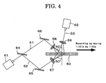
- the optical recording and reproducing apparatus shown in FIG. 4 is an example of a typical holographic recording and reproducing apparatus in which an optical recording medium is irradiated with information beam and reference beam respectively from different directions.
- the beam from a light source 61 is split into two rays, one forming information beam 51 that passed through a half mirror 64, and one forming a reference beam 52 reflected by the half mirror 64.
- the information beam 51 is expanded through a mirror 66 and a beam expander 68, and is shined on the recording layer of an optical recording medium 50.
- the reference beam 52 is expanded through a mirror 65 and a beam expander 67, and is shined on a surface of the recording layer opposite to the surface on which information beam 51 is shined. In this way the information beam 51 and reference beam 52 create an interference fringe, which is recorded on the recording layer as optical information.
- recording is repeated by moving the optical recording medium 50 little by little as shown in FIG. 4 , enabling multiplex recording in the optical recording medium 50.
- the treating unit of the present invention containing the light diffusion member is provided adjacent to at least any of light sources 61 and 62 (not shown).
- FIG. 5 shows the entire configuration of an optical recording and reproducing apparatus of an embodiment of the present invention.
- the optical recording and reproducing apparatus 100 includes a spindle 81 to which an optical recording medium 20 is mounted, a spindle motor 82 for rotating the spindle 81, and a spindle servo circuit 83 for controlling the spindle motor 82 so that the rotation speed of the optical recording medium 20 is maintained at a predetermined level.
- the optical recording and reproducing apparatus 100 further includes a pickup 31 and a drive device 84.
- the pickup 31 is used for recording information by applying an information beam and a reference beam to the optical recording medium 20; and for reproducing information recorded in the optical recording medium 20 by applying a reference beam for reproduction to the optical recording medium 20 and by detecting a reproduction beam (light).
- the drive device 84 enables the pickup 31 to move in the radial direction of the optical recording medium 20.
- the treating unit of the present invention having the light diffusion member is provided adjacent to the pickup 31 (not shown).
- the optical recording and reproducing apparatus 100 further includes a detection circuit 85, a focus servo circuit 86, a tracking servo circuit 87 and a slide servo circuit 88.
- the detection circuit 85 is for detecting a focus error signal FE, a tracking error signal TE and a reproduction signal RF from signals output from the pickup 31.
- the focus servo circuit 86 carries out a focus servo operation by driving an actuator provided inside the pickup 31, on the basis of the focus error signal FE detected by the detection circuit 85, so as to move an objective lens (not shown) in the thickness direction of the optical recording medium 20.
- the tracking servo circuit 87 carries out a tracking servo operation by driving an actuator provided inside the pickup 31, on the basis of the tracking error signal TE detected by the detection circuit 85, so as to move the objective lens in the radial direction of the optical recording medium 20.
- the slide servo circuit 88 carries out a slide servo operation by controlling the drive device 84, on the basis of the tracking error signal TE and commands from a controller (described below), so as to move the pickup 31 in the radial direction of the optical recording medium 20.
- the optical recording and reproducing apparatus 100 further includes a signal processing circuit 89, a controller 90 and an operation unit 91.
- the signal processing circuit 89 decodes data output from a CMOS or a CCD array (described below) in the pickup 31 so as to reproduce data recorded in a data area of the optical recording medium 20.
- this circuit creates a reference clock on the basis of a reproduction signal RF detected by the detection circuit 85; and distinguishes individual addresses.
- the controller 90 controls the overall optical recording and reproducing apparatus 100.
- the operation unit 91 gives a variety of commands to the controller 90.
- the controller 90 furthermore, receives the reference clock and address information output from the signal processing circuit 89, and controls, for example, the pickup 31, the spindle servo circuit 83 and the slide servo circuit 88.
- the spindle servo circuit 83 receives the reference clock output from the signal processing circuit 89.
- the controller 90 includes a CPU (central processing unit), a ROM (read only memory) and a RAM (random access memory), and the CPU realizes the function of the controller 90 by executing programs stored in the ROM on the RAM serving as a working area.
- An optical recording and reproducing apparatus of the present invention contains a device for treating an optical recording medium of the present invention, enabling to subject a thick recording layer which has recorded information using volume holography to insensitization without degrading information, thereby enabling to enhance long-term storage property and durability against repetitive reproduction of a recorded image.
- the present invention can solve the conventional problems and provide the method for treating an optical recording medium and device for treating an optical recording medium, in which an optical recording medium having a thick recording layer which has recorded information using holography is subjected to insensitization without degrading information, thereby enabling to enhance long-term storage property and durability against repetitive reproduction of a recorded image, and provide the optical recording and reproducing apparatus containing the device for treating an optical recording medium.
- a write-once read-many (WORM) optical recording medium was produced by laminating a second substrate, a reflective layer, an adhesive layer, a selective reflection layer, a protective layer (a second gap layer) and a first substrate in this order.
- WORM write-once read-many
- the second substrate was produced from a polycarbonate resin so as to have a diameter, inner diameter and thickness of 120 mm, 15 mm and 0.6 mm, respectively.
- the first substrate used was a polycarbonate resin-substrate having a diameter, inner diameter and thickness of 120 mm, 15 mm and 0.6 mm, respectively, which was generally used for DVD+RW.
- This substrate had a surface with a servo pit pattern having a track pitch, pit depth and pit width of 0.74 ⁇ m, 140 nm and 300 nm, respectively.
- the reflective layer was formed on the surface of the servo pit pattern of the first substrate. Specifically, the reflective layer was formed from Ag by DC magnetron sputtering so as to attain a thickness of 150 nm.
- an adhesive SD640, manufactured by DIC Corporation
- an adhesive was spin coated so as to form an adhesive layer having a thickness of 20 ⁇ m, and then the selective reflection layer (a first gap layer) produced as described below was formed thereon.
- Coating liquids for forming a holographic recording layer consisting of the following composition were prepared separately in Tank A and Tank B under nitrogen atmosphere. Dry nitrogen was filled in the tanks after the coating liquids were prepared.
- the disc-shaped selective reflection layer was bonded onto the first substrate over which the reflective layer and the adhesive layer (first gap layer) were formed. Specifically, bonding of the selective reflection layer was carried out such that the base film surface thereof faced the servo pit pattern and that no air bubbles existed between the layer and the substrate. Thus, the selective reflection layer was formed on the first substrate.
- a composition for protective layer containing an adhesive (SD640, manufactured by DIC Corporation) was coated on the selective reflection layer by spin coating so as to have a thickness of 20 ⁇ m, to thereby form the protective layer (second gap layer).
- An S/N ratio was obtained by recording and reproducing information in the optical recording medium produced in Production Example 1 by a co-linear optical recording and reproducing tester (SHOT-2000 manufactured by Pulstec Industrial Co.), and an image quality of a reproduced image was visually evaluated based on the following criteria.
- the total amount of light exposure was 30,000 mJ/cm 2 .
- the half width of wavelength for an energy intensity of the treatment light is 155 nm.
- the optical recording medium which had been subjected to insensitization was mounted again on the co-linear optical recording and reproducing tester, and reproduced the recorded information to thereby obtain an S/N ratio and evaluate an image quality of a reproduced image based on the following criteria.
- a reproduction beam (wavelength of 532 nm) was continuously applied to the optical recording medium at a reproduced signal position so that the total amount of light exposure was 100 J/cm 2 .
- the recorded information was reproduced again to thereby obtain an S/N ratio and evaluate an image quality of a reproduced image based on the following criteria. The results are respectively shown in Table 1.
- a method and device for treating an optical recording medium of the present invention can treat a recording layer which has recorded information by subjecting it to insensitization without degrading information, and can enhance long-term storage property and durability against repetitive reproduction of a recorded image, thereby used for various types of volume holographic optical recording media capable of high-density image recording.
Landscapes
- Physics & Mathematics (AREA)
- Optics & Photonics (AREA)
- General Physics & Mathematics (AREA)
- Holo Graphy (AREA)
- Optical Recording Or Reproduction (AREA)
- Optical Head (AREA)
- Optical Record Carriers And Manufacture Thereof (AREA)
Applications Claiming Priority (2)
| Application Number | Priority Date | Filing Date | Title |
|---|---|---|---|
| JP2006098955A JP4698470B2 (ja) | 2006-03-31 | 2006-03-31 | 光記録媒体の処理方法及び処理装置、並びに光記録再生装置 |
| PCT/JP2006/325207 WO2007116565A1 (ja) | 2006-03-31 | 2006-12-18 | 光記録媒体の処理方法及び処理装置、並びに光記録再生装置 |
Publications (3)
| Publication Number | Publication Date |
|---|---|
| EP2012198A1 true EP2012198A1 (de) | 2009-01-07 |
| EP2012198A4 EP2012198A4 (de) | 2010-01-06 |
| EP2012198B1 EP2012198B1 (de) | 2010-11-24 |
Family
ID=38580867
Family Applications (1)
| Application Number | Title | Priority Date | Filing Date |
|---|---|---|---|
| EP06834917A Not-in-force EP2012198B1 (de) | 2006-03-31 | 2006-12-18 | Verfahren und geräte zum verarbeiten eines optischen aufzeichnungsmediums und optische aufzeichnungs-/wiedergabevorrichtung |
Country Status (5)
| Country | Link |
|---|---|
| US (1) | US20100061212A1 (de) |
| EP (1) | EP2012198B1 (de) |
| JP (1) | JP4698470B2 (de) |
| DE (1) | DE602006018535D1 (de) |
| WO (1) | WO2007116565A1 (de) |
Families Citing this family (5)
| Publication number | Priority date | Publication date | Assignee | Title |
|---|---|---|---|---|
| JP2007279475A (ja) * | 2006-04-10 | 2007-10-25 | Pulstec Industrial Co Ltd | ホログラム記録装置及びホログラム記録方法 |
| US20110318506A1 (en) * | 2010-06-24 | 2011-12-29 | Oracle International Corporation | Optical Tape Media Patterning Using Cationic Polymerizable Monomers |
| KR20140082692A (ko) * | 2011-10-12 | 2014-07-02 | 바이엘 인텔렉쳐 프로퍼티 게엠베하 | 폴리우레탄-기재 광중합체 제제에서의 사슬 전달 시약 |
| US10720259B2 (en) * | 2014-09-02 | 2020-07-21 | Tokyo University Of Science Foundation | Electroconductive film and method for manufacturing electroconductive pattern |
| EP3319892B1 (de) | 2015-07-08 | 2019-12-18 | Inventio AG | Bedienfeld für einen aufzug zur bereitstellung von optionen zur anzeige zusätzlicher etageninformationen |
Family Cites Families (87)
| Publication number | Priority date | Publication date | Assignee | Title |
|---|---|---|---|---|
| US161811A (en) | 1875-04-06 | Improvement in mechanisms for feeding heel-stiffeners or counter-blanks | ||
| US339049A (en) | 1886-03-30 | Sole-edge-burnishing | ||
| US410201A (en) | 1889-09-03 | Bent for suspension-bridges | ||
| US2833827A (en) | 1955-01-17 | 1958-05-06 | Bayer Ag | Tri (3, 5-di lower alkyl-4-hydroxy phenyl)-sulfonium chlorides and method of preparing same |
| US3479185A (en) | 1965-06-03 | 1969-11-18 | Du Pont | Photopolymerizable compositions and layers containing 2,4,5-triphenylimidazoyl dimers |
| US3694218A (en) * | 1970-03-03 | 1972-09-26 | Hughes Aircraft Co | Method of hologram recording |
| US3987037A (en) | 1971-09-03 | 1976-10-19 | Minnesota Mining And Manufacturing Company | Chromophore-substituted vinyl-halomethyl-s-triazines |
| US3905815A (en) | 1971-12-17 | 1975-09-16 | Minnesota Mining & Mfg | Photopolymerizable sheet material with diazo resin layer |
| US4069056A (en) | 1974-05-02 | 1978-01-17 | General Electric Company | Photopolymerizable composition containing group Va aromatic onium salts |
| GB1512982A (en) | 1974-05-02 | 1978-06-01 | Gen Electric | Salts |
| US4173476A (en) | 1978-02-08 | 1979-11-06 | Minnesota Mining And Manufacturing Company | Complex salt photoinitiator |
| JPS6053300B2 (ja) | 1978-08-29 | 1985-11-25 | 富士写真フイルム株式会社 | 感光性樹脂組成物 |
| US4311783A (en) | 1979-08-14 | 1982-01-19 | E. I. Du Pont De Nemours And Company | Dimers derived from unsymmetrical 2,4,5,-triphenylimidazole compounds as photoinitiators |
| US4518676A (en) | 1982-09-18 | 1985-05-21 | Ciba Geigy Corporation | Photopolymerizable compositions containing diaryliodosyl salts |
| US4590287A (en) | 1983-02-11 | 1986-05-20 | Ciba-Geigy Corporation | Fluorinated titanocenes and photopolymerizable composition containing same |
| JPH0629285B2 (ja) | 1983-10-14 | 1994-04-20 | 三菱化成株式会社 | 光重合性組成物 |
| JPS60239736A (ja) | 1984-05-14 | 1985-11-28 | Fuji Photo Film Co Ltd | 感光性組成物 |
| US4713401A (en) | 1984-12-20 | 1987-12-15 | Martin Riediker | Titanocenes and a radiation-polymerizable composition containing these titanocenes |
| JPS61169837A (ja) | 1985-01-22 | 1986-07-31 | Fuji Photo Film Co Ltd | 光可溶化組成物 |
| JP2525568B2 (ja) | 1985-01-18 | 1996-08-21 | 富士写真フイルム株式会社 | 光可溶化組成物 |
| JPS61169835A (ja) | 1985-01-22 | 1986-07-31 | Fuji Photo Film Co Ltd | 光可溶化組成物 |
| JPH0766185B2 (ja) | 1985-09-09 | 1995-07-19 | 富士写真フイルム株式会社 | 感光性組成物 |
| US4622286A (en) | 1985-09-16 | 1986-11-11 | E. I. Du Pont De Nemours And Company | Photoimaging composition containing admixture of leuco dye and 2,4,5-triphenylimidazolyl dimer |
| CA1284740C (en) | 1985-11-20 | 1991-06-11 | Peter Gottschalk | Photosensitive materials containing ionic dye compounds as initiators |
| US4772541A (en) | 1985-11-20 | 1988-09-20 | The Mead Corporation | Photohardenable compositions containing a dye borate complex and photosensitive materials employing the same |
| DE3604581A1 (de) | 1986-02-14 | 1987-08-20 | Basf Ag | 4-acylbenzylsulfoniumsalze, ihre herstellung sowie sie enthaltende photohaertbare gemische und aufzeichnungsmaterialien |
| DE3604580A1 (de) | 1986-02-14 | 1987-08-20 | Basf Ag | Haertbare mischungen, enthaltend n-sulfonylaminosulfoniumsalze als kationisch wirksame katalysatoren |
| JPS62212401A (ja) | 1986-03-14 | 1987-09-18 | Fuji Photo Film Co Ltd | 光重合性組成物 |
| AU599400B2 (en) | 1986-08-01 | 1990-07-19 | Ciba-Geigy Ag | Titanocenes and their use |
| JPS6370243A (ja) | 1986-09-11 | 1988-03-30 | Fuji Photo Film Co Ltd | 感光性組成物 |
| US5124815A (en) * | 1986-11-04 | 1992-06-23 | Kaiser Optical Systems | Method for forming holographic optical elements free of secondary fringes |
| US4760013A (en) | 1987-02-17 | 1988-07-26 | International Business Machines Corporation | Sulfonium salt photoinitiators |
| JPH0743536B2 (ja) | 1987-05-29 | 1995-05-15 | 富士写真フイルム株式会社 | 感光性組成物 |
| DE3721741A1 (de) | 1987-07-01 | 1989-01-12 | Basf Ag | Strahlungsempfindliches gemisch fuer lichtempfindliche beschichtungsmaterialien |
| DE3721740A1 (de) | 1987-07-01 | 1989-01-12 | Basf Ag | Sulfoniumsalze mit saeurelabilen gruppierungen |
| US5026625A (en) | 1987-12-01 | 1991-06-25 | Ciba-Geigy Corporation | Titanocenes, the use thereof, and n-substituted fluoroanilines |
| JPH01152109A (ja) | 1987-12-09 | 1989-06-14 | Toray Ind Inc | 光重合性組成物 |
| US4818045A (en) * | 1987-12-29 | 1989-04-04 | Kaiser Optical Systems | Holographic optical element having periphery with gradually decreasing diffraction efficiency and method of construction |
| US4933377A (en) | 1988-02-29 | 1990-06-12 | Saeva Franklin D | Novel sulfonium salts and the use thereof as photoinitiators |
| EP0334338A3 (de) | 1988-03-24 | 1990-06-20 | Dentsply International, Inc. | Titanatinitiatoren für lichthärtende Zusammensetzungen |
| JP2757375B2 (ja) | 1988-06-02 | 1998-05-25 | 東洋紡績株式会社 | 光重合性組成物 |
| CA2002873A1 (en) | 1988-11-21 | 1990-05-21 | Franklin Donald Saeva | Onium salts and the use thereof as photoinitiators |
| JPH02150848A (ja) | 1988-12-02 | 1990-06-11 | Hitachi Ltd | 光退色性放射線感応性組成物およびそれを用いたパターン形成法 |
| US5040237A (en) | 1989-03-31 | 1991-08-13 | E. F. Johnson Company | Method and apparatus for an alternate home channel for a land mobile transmission trunked communication system |
| JPH02296514A (ja) | 1989-05-12 | 1990-12-07 | Matsushita Electric Ind Co Ltd | 車両用サスペンション制御装置 |
| JPH04365049A (ja) | 1991-06-12 | 1992-12-17 | Fuji Photo Film Co Ltd | 感光性組成物 |
| JP2764769B2 (ja) | 1991-06-24 | 1998-06-11 | 富士写真フイルム株式会社 | 光重合性組成物 |
| JPH0583588A (ja) | 1991-09-24 | 1993-04-02 | Omron Corp | 画像処理装置 |
| US6479193B1 (en) * | 1992-06-30 | 2002-11-12 | Nippon Sheet Glass Co., Ltd. | Optical recording film and process for production thereof |
| JP2929858B2 (ja) | 1992-08-14 | 1999-08-03 | 東洋インキ製造株式会社 | 重合性組成物および重合方法 |
| JPH06175553A (ja) | 1992-12-03 | 1994-06-24 | Toyo Ink Mfg Co Ltd | ホログラム記録媒体及びそれを用いた体積位相型ホログラムの製造方法 |
| JPH06175554A (ja) | 1992-12-03 | 1994-06-24 | Toyo Ink Mfg Co Ltd | 体積位相型ホログラムの製造方法 |
| JPH06175561A (ja) | 1992-12-04 | 1994-06-24 | Toyo Ink Mfg Co Ltd | ホログラム記録媒体及びそれを用いた体積位相型ホログラムの製造方法 |
| JPH06175564A (ja) | 1992-12-04 | 1994-06-24 | Toyo Ink Mfg Co Ltd | ホログラム記録材料及びそれを用いた体積位相型ホログラムの製造方法 |
| JP2849021B2 (ja) | 1993-04-12 | 1999-01-20 | 日本ペイント株式会社 | 体積ホログラム記録用感光性組成物 |
| JPH06348011A (ja) | 1993-06-04 | 1994-12-22 | Toyo Ink Mfg Co Ltd | 光重合性組成物 |
| JPH07104643A (ja) | 1993-09-30 | 1995-04-21 | Toppan Printing Co Ltd | ホログラム記録材料及びホログラム記録用媒体 |
| JPH07128785A (ja) | 1993-11-02 | 1995-05-19 | Konica Corp | 画像形成材料及び画像形成方法 |
| JPH07140589A (ja) | 1993-11-19 | 1995-06-02 | Konica Corp | 画像形成材料および画像形成方法 |
| JPH07199777A (ja) | 1993-12-28 | 1995-08-04 | Toppan Printing Co Ltd | ホログラム記録用感光性樹脂組成物及びホログラム記録用媒体 |
| JPH07199779A (ja) | 1993-12-28 | 1995-08-04 | Toppan Printing Co Ltd | ホログラム記録材料及びホログラム記録用媒体 |
| JP3321288B2 (ja) | 1994-04-25 | 2002-09-03 | 日本ペイント株式会社 | 近赤外光重合性組成物 |
| JPH07306527A (ja) | 1994-05-11 | 1995-11-21 | Konica Corp | 画像形成材料及び画像形成方法 |
| JPH08101499A (ja) | 1994-10-03 | 1996-04-16 | Nippon Paint Co Ltd | 体積ホログラム記録用感光性組成物、及びそれを用いた記録媒体ならびに体積ホログラム形成方法 |
| JPH08108621A (ja) | 1994-10-06 | 1996-04-30 | Konica Corp | 画像記録媒体及びそれを用いる画像形成方法 |
| JP3532679B2 (ja) | 1995-11-08 | 2004-05-31 | ジヤトコ株式会社 | 自動変速機の制御装置 |
| TW467933B (en) | 1995-11-24 | 2001-12-11 | Ciba Sc Holding Ag | Photopolymerizable compositions comprising borate photoinitiators from monoboranes and the use thereof |
| AU717137B2 (en) | 1995-11-24 | 2000-03-16 | Ciba Specialty Chemicals Holding Inc. | Borate coinitiators for photopolymerization |
| MY132867A (en) | 1995-11-24 | 2007-10-31 | Ciba Specialty Chemicals Holding Inc | Acid-stable borates for photopolymerization |
| US5721630A (en) * | 1996-03-12 | 1998-02-24 | Polaroid Corporation | High-efficiency reflective holographic diffuser and method for making thereof |
| US5874187A (en) * | 1996-08-15 | 1999-02-23 | Lucent Technologies Incorporated | Photo recording medium |
| SG77689A1 (en) | 1998-06-26 | 2001-01-16 | Ciba Sc Holding Ag | New o-acyloxime photoinitiators |
| JP3889530B2 (ja) | 1998-08-17 | 2007-03-07 | コダックポリクロームグラフィックス株式会社 | 光重合性組成物、光重合性平版印刷版及び画像形成方法 |
| DK199901098A (da) | 1998-08-18 | 2000-02-19 | Ciba Sc Holding Ag | Sylfonyloximer til i-linie-fotoresists med høj følsomhed og høj resisttykkelse |
| GB9906327D0 (en) * | 1999-03-19 | 1999-05-12 | Pilkington Plc | Production of sheet glass |
| US6686097B2 (en) * | 1999-06-01 | 2004-02-03 | Adil Lahrichi | Reversible hologram fixation in photorefractive materials using incoherent ultraviolet light |
| JP4365494B2 (ja) | 1999-10-27 | 2009-11-18 | 日本ペイント株式会社 | 体積ホログラム記録用感光組成物およびこれから得られるホログラム |
| JP4191887B2 (ja) | 2000-09-27 | 2008-12-03 | 富士フイルム株式会社 | 平版印刷版原版 |
| JP2003050534A (ja) * | 2001-01-25 | 2003-02-21 | Mitsubishi Chemicals Corp | 光メモリ素子,光メモリ素子の記録方法及び光メモリ素子の再生方法 |
| JP2002328465A (ja) | 2001-04-27 | 2002-11-15 | Fuji Photo Film Co Ltd | 平版印刷版原版 |
| JP3552709B2 (ja) * | 2002-07-17 | 2004-08-11 | 株式会社デンソー | ホログラムスクリーン |
| JP3896098B2 (ja) * | 2003-06-27 | 2007-03-22 | 株式会社東芝 | ホログラム記録媒体およびその作製方法 |
| JP4479282B2 (ja) * | 2004-03-03 | 2010-06-09 | ソニー株式会社 | 記録媒体キュアー方法及びホログラム記録装置 |
| JP2005275273A (ja) * | 2004-03-26 | 2005-10-06 | Fuji Photo Film Co Ltd | ホログラム記録材料、ホログラム記録方法及び光記録媒体 |
| US7567381B2 (en) * | 2004-12-20 | 2009-07-28 | Mitsubishi Gas Chemical Company, Inc. | Plastic sheet |
| US20060281021A1 (en) * | 2005-05-26 | 2006-12-14 | Inphase Technologies, Inc. | Illuminative treatment of holographic media |
| JP2007003692A (ja) * | 2005-06-22 | 2007-01-11 | Fujifilm Holdings Corp | 光記録方法、光記録装置及び光記録媒体 |
-
2006
- 2006-03-31 JP JP2006098955A patent/JP4698470B2/ja not_active Expired - Fee Related
- 2006-12-18 WO PCT/JP2006/325207 patent/WO2007116565A1/ja not_active Ceased
- 2006-12-18 US US12/295,424 patent/US20100061212A1/en not_active Abandoned
- 2006-12-18 EP EP06834917A patent/EP2012198B1/de not_active Not-in-force
- 2006-12-18 DE DE602006018535T patent/DE602006018535D1/de active Active
Also Published As
| Publication number | Publication date |
|---|---|
| JP4698470B2 (ja) | 2011-06-08 |
| EP2012198A4 (de) | 2010-01-06 |
| EP2012198B1 (de) | 2010-11-24 |
| JP2007272036A (ja) | 2007-10-18 |
| DE602006018535D1 (de) | 2011-01-05 |
| WO2007116565A1 (ja) | 2007-10-18 |
| US20100061212A1 (en) | 2010-03-11 |
Similar Documents
| Publication | Publication Date | Title |
|---|---|---|
| EP1708180A2 (de) | Optisches Informationsaufzeichnungsverfahren, optische Informationsaufzeichnungsvorrichtung und optisches Informationsaufzeichnungsmedium | |
| EP1610191A1 (de) | Holographisches aufzeichnungsmedium und aufzeichnungsverfahren dafür | |
| EP2003520A9 (de) | Lichtempfindliche zusammensetzung, optisches aufzeichnungsmedium und herstellungsverfahren dafür, optisches aufzeichnungsmedium und optische aufzeichnungsvorrichtung | |
| US20070042275A1 (en) | Composition for optical recording, optical recording medium, and production method thereof | |
| EP2012198B1 (de) | Verfahren und geräte zum verarbeiten eines optischen aufzeichnungsmediums und optische aufzeichnungs-/wiedergabevorrichtung | |
| JP2008076674A (ja) | ホログラム記録媒体用組成物、並びにホログラム記録媒体及びその製造方法 | |
| JP2007257802A (ja) | 光記録方法、光記録装置及び光記録媒体 | |
| JP2007171673A (ja) | 光記録媒体、並びに光記録装置、光記録方法及び光再生方法 | |
| US20070072088A1 (en) | Composition for hologram recording media, hologram recording medium and method for producing the same, hologram recording method and hologram reproducing method | |
| US20070077498A1 (en) | Optical recording composition, optical recording medium and production method thereof, optical recording method and optical recording apparatus | |
| JP2006301171A (ja) | 光記録媒体及びその製造方法、並びに、光記録媒体の記録方法及び光記録媒体の再生方法 | |
| JP2007279585A (ja) | 感光性組成物、並びに光記録媒体、光記録方法及び光記録装置 | |
| EP1760709A1 (de) | Optische Informationsaufzeichnungsmedien und Verfahren zu ihrer Herstellung | |
| JP2007207386A (ja) | 光記録再生装置、光記録方法及び光再生方法 | |
| US7974171B2 (en) | Optical recording method, optical reproduction method, optical recording apparatus, and optical recording medium | |
| JP2006301127A (ja) | 光記録媒体及びその製造方法、並びに、光記録媒体の記録方法及び光記録媒体の再生方法 | |
| JP2009048060A (ja) | ホログラフィック記録用組成物、ホログラフィック記録媒体および情報記録方法 | |
| JP2007242193A (ja) | 光記録再生装置及び光記録媒体のデータ破壊方法 | |
| JP2007041323A (ja) | 光記録媒体及光記録装置 | |
| JP2008070464A (ja) | 感光性組成物、並びに光記録媒体、光記録方法及び光記録装置 | |
| JP2007101881A (ja) | ホログラム記録媒体及びその製造方法 | |
| JP2008281661A (ja) | ホログラフィック記録媒体の製造方法 | |
| JP2006349770A (ja) | 光記録媒体及びその製造方法、並びに、光記録媒体の記録方法及び光記録媒体の再生方法 | |
| JP2007187968A (ja) | ホログラフィック記録用組成物及びその製造方法、並びに光記録媒体 | |
| JP2007207387A (ja) | 光再生方法及び光再生装置 |
Legal Events
| Date | Code | Title | Description |
|---|---|---|---|
| PUAI | Public reference made under article 153(3) epc to a published international application that has entered the european phase |
Free format text: ORIGINAL CODE: 0009012 |
|
| 17P | Request for examination filed |
Effective date: 20081030 |
|
| AK | Designated contracting states |
Kind code of ref document: A1 Designated state(s): AT BE BG CH CY CZ DE DK EE ES FI FR GB GR HU IE IS IT LI LT LU LV MC NL PL PT RO SE SI SK TR |
|
| AX | Request for extension of the european patent |
Extension state: AL BA HR MK RS |
|
| DAX | Request for extension of the european patent (deleted) | ||
| RBV | Designated contracting states (corrected) |
Designated state(s): DE FR GB |
|
| A4 | Supplementary search report drawn up and despatched |
Effective date: 20091204 |
|
| GRAP | Despatch of communication of intention to grant a patent |
Free format text: ORIGINAL CODE: EPIDOSNIGR1 |
|
| GRAS | Grant fee paid |
Free format text: ORIGINAL CODE: EPIDOSNIGR3 |
|
| GRAA | (expected) grant |
Free format text: ORIGINAL CODE: 0009210 |
|
| AK | Designated contracting states |
Kind code of ref document: B1 Designated state(s): DE FR GB |
|
| REG | Reference to a national code |
Ref country code: GB Ref legal event code: FG4D |
|
| REF | Corresponds to: |
Ref document number: 602006018535 Country of ref document: DE Date of ref document: 20110105 Kind code of ref document: P |
|
| PGFP | Annual fee paid to national office [announced via postgrant information from national office to epo] |
Ref country code: GB Payment date: 20101224 Year of fee payment: 5 |
|
| PGFP | Annual fee paid to national office [announced via postgrant information from national office to epo] |
Ref country code: DE Payment date: 20110128 Year of fee payment: 5 |
|
| PLBE | No opposition filed within time limit |
Free format text: ORIGINAL CODE: 0009261 |
|
| STAA | Information on the status of an ep patent application or granted ep patent |
Free format text: STATUS: NO OPPOSITION FILED WITHIN TIME LIMIT |
|
| 26N | No opposition filed |
Effective date: 20110825 |
|
| REG | Reference to a national code |
Ref country code: DE Ref legal event code: R097 Ref document number: 602006018535 Country of ref document: DE Effective date: 20110825 |
|
| PGFP | Annual fee paid to national office [announced via postgrant information from national office to epo] |
Ref country code: FR Payment date: 20111219 Year of fee payment: 6 |
|
| GBPC | Gb: european patent ceased through non-payment of renewal fee |
Effective date: 20121218 |
|
| REG | Reference to a national code |
Ref country code: FR Ref legal event code: ST Effective date: 20130830 |
|
| REG | Reference to a national code |
Ref country code: DE Ref legal event code: R119 Ref document number: 602006018535 Country of ref document: DE Effective date: 20130702 |
|
| PG25 | Lapsed in a contracting state [announced via postgrant information from national office to epo] |
Ref country code: DE Free format text: LAPSE BECAUSE OF NON-PAYMENT OF DUE FEES Effective date: 20130702 |
|
| PG25 | Lapsed in a contracting state [announced via postgrant information from national office to epo] |
Ref country code: FR Free format text: LAPSE BECAUSE OF NON-PAYMENT OF DUE FEES Effective date: 20130102 Ref country code: GB Free format text: LAPSE BECAUSE OF NON-PAYMENT OF DUE FEES Effective date: 20121218 |