EP2523831B2 - Caméra de véhicule et procédé d'étalonnage périodique de caméra de véhicule - Google Patents
Caméra de véhicule et procédé d'étalonnage périodique de caméra de véhicule Download PDFInfo
- Publication number
- EP2523831B2 EP2523831B2 EP11732612.4A EP11732612A EP2523831B2 EP 2523831 B2 EP2523831 B2 EP 2523831B2 EP 11732612 A EP11732612 A EP 11732612A EP 2523831 B2 EP2523831 B2 EP 2523831B2
- Authority
- EP
- European Patent Office
- Prior art keywords
- camera
- microcontroller
- vehicle
- reference point
- vision system
- Prior art date
- Legal status (The legal status is an assumption and is not a legal conclusion. Google has not performed a legal analysis and makes no representation as to the accuracy of the status listed.)
- Active
Links
Images






Classifications
-
- G—PHYSICS
- G06—COMPUTING OR CALCULATING; COUNTING
- G06T—IMAGE DATA PROCESSING OR GENERATION, IN GENERAL
- G06T7/00—Image analysis
- G06T7/80—Analysis of captured images to determine intrinsic or extrinsic camera parameters, i.e. camera calibration
-
- B—PERFORMING OPERATIONS; TRANSPORTING
- B60—VEHICLES IN GENERAL
- B60R—VEHICLES, VEHICLE FITTINGS, OR VEHICLE PARTS, NOT OTHERWISE PROVIDED FOR
- B60R11/00—Arrangements for holding or mounting articles, not otherwise provided for
- B60R11/04—Mounting of cameras operative during drive; Arrangement of controls thereof relative to the vehicle
-
- G—PHYSICS
- G06—COMPUTING OR CALCULATING; COUNTING
- G06T—IMAGE DATA PROCESSING OR GENERATION, IN GENERAL
- G06T11/00—Two-dimensional [2D] image generation
- G06T11/60—Creating or editing images; Combining images with text
-
- B—PERFORMING OPERATIONS; TRANSPORTING
- B60—VEHICLES IN GENERAL
- B60R—VEHICLES, VEHICLE FITTINGS, OR VEHICLE PARTS, NOT OTHERWISE PROVIDED FOR
- B60R2300/00—Details of viewing arrangements using cameras and displays, specially adapted for use in a vehicle
- B60R2300/30—Details of viewing arrangements using cameras and displays, specially adapted for use in a vehicle characterised by the type of image processing
- B60R2300/304—Details of viewing arrangements using cameras and displays, specially adapted for use in a vehicle characterised by the type of image processing using merged images, e.g. merging camera image with stored images
-
- B—PERFORMING OPERATIONS; TRANSPORTING
- B60—VEHICLES IN GENERAL
- B60R—VEHICLES, VEHICLE FITTINGS, OR VEHICLE PARTS, NOT OTHERWISE PROVIDED FOR
- B60R2300/00—Details of viewing arrangements using cameras and displays, specially adapted for use in a vehicle
- B60R2300/40—Details of viewing arrangements using cameras and displays, specially adapted for use in a vehicle characterised by the details of the power supply or the coupling to vehicle components
- B60R2300/402—Image calibration
-
- B—PERFORMING OPERATIONS; TRANSPORTING
- B60—VEHICLES IN GENERAL
- B60R—VEHICLES, VEHICLE FITTINGS, OR VEHICLE PARTS, NOT OTHERWISE PROVIDED FOR
- B60R2300/00—Details of viewing arrangements using cameras and displays, specially adapted for use in a vehicle
- B60R2300/80—Details of viewing arrangements using cameras and displays, specially adapted for use in a vehicle characterised by the intended use of the viewing arrangement
- B60R2300/806—Details of viewing arrangements using cameras and displays, specially adapted for use in a vehicle characterised by the intended use of the viewing arrangement for aiding parking
-
- G—PHYSICS
- G06—COMPUTING OR CALCULATING; COUNTING
- G06T—IMAGE DATA PROCESSING OR GENERATION, IN GENERAL
- G06T2207/00—Indexing scheme for image analysis or image enhancement
- G06T2207/10—Image acquisition modality
- G06T2207/10016—Video; Image sequence
-
- G—PHYSICS
- G06—COMPUTING OR CALCULATING; COUNTING
- G06T—IMAGE DATA PROCESSING OR GENERATION, IN GENERAL
- G06T2207/00—Indexing scheme for image analysis or image enhancement
- G06T2207/30—Subject of image; Context of image processing
- G06T2207/30248—Vehicle exterior or interior
- G06T2207/30252—Vehicle exterior; Vicinity of vehicle
-
- G—PHYSICS
- G06—COMPUTING OR CALCULATING; COUNTING
- G06T—IMAGE DATA PROCESSING OR GENERATION, IN GENERAL
- G06T2207/00—Indexing scheme for image analysis or image enhancement
- G06T2207/30—Subject of image; Context of image processing
- G06T2207/30248—Vehicle exterior or interior
- G06T2207/30252—Vehicle exterior; Vicinity of vehicle
- G06T2207/30264—Parking
Definitions
- the present invention relates to cameras for use in vehicles, and more particularly to a camera for use in a vehicle wherein an overlay is applied to the image on board the camera.
- a typical camera for mounting on a vehicle has a lens member, an imager, a circuit board and housing members that connect together.
- Some cameras have the capability to apply an overlay onto the image received by the imager, and to send the image with the overlay in it directly to an in-vehicle display for viewing by the vehicle driver.
- the camera system can become misaligned. This can occur gradually from a variety of factors. It can also occur suddenly, such as, during an accident. Whether gradually or because of an accident, the misalignment can occur without being detected upon visual inspection of the camera.
- JP 2009212734 discloses a vision system according to the preamble of claim 1.
- the camera includes a lens and an imager.
- the lens is positioned to capture a view exterior a vehicle, wherein, with the camera installed at the vehicle, the camera includes a portion of the vehicle.
- the imager includes an image sensor and an imager microcontroller.
- the image sensor is configured to receive images from the lens.
- the camera microcontroller has a statistics engine generating statistical data from the images, and is operable to control the application of an overlay to the images.
- An in-vehicle display is operable to display images captured by the imager.
- the camera microcontroller is operable to receive statistical data from the imager microcontroller of the imager, and the microcontroller is further operable to detect a reference point in the images using the statistical data and, responsive to a determination of an offset of the detected reference point relative to an expected location of the reference point, the camera microcontroller is operable to determine an offset amount with which to shift the overlay on the images.
- the camera microcontroller is operable to detect reference points during reference point detection cycles, wherein the reference point detection cycles are conducted on different driving days and at different driving times. Responsive to the determined offset, the camera microcontroller shifts the overlay applied to the images.
- FIG. 1 shows a vehicle 10 that includes a camera 11 sends images 25 to an in-vehicle display 24.
- the camera 11 is configured to be calibrated periodically after it has been installed on the vehicle 10 in accordance with an embodiment of the present invention.
- the camera 11 includes a lens assembly 12, a housing 14, which may include a lens holder 14a and a rear housing member 14b, an imager 16 and a camera microcontroller 18.
- the lens assembly 12 is an assembly that includes a lens 20 and a lens barrel 22.
- the lens 20 may be held in the lens barrel 22 in any suitable way.
- the lens barrel 22 may be held in the lens holder 14a in any suitable way.
- the imager 16 may be any suitable type of imager 16 such as the imager model no. MT9V126 provided by Aptina Imaging, San Jose, CA and includes an image sensor 16a, such as a CMOS sensor or a CCD sensor, and an imager microcontroller 16b that performs several functions.
- the imager microcontroller 16b applies a distortion correction algorithm to the images 25 received by the image sensor 16a.
- the imager microcontroller 16b applies graphical overlays to the images 25.
- the images 25 have been processed by the imager microcontroller 16b they are sent to the in-vehicle display 24 via an electrical conduit shown at 27a, which may be, for example a coaxial cable.
- the microcontroller 18 may be any suitable type of microcontroller, such as the microcontroller model no. PIC24HJ128GP502 provided by Microchip Technology, Chandler, AZ.
- the microcontroller 18 includes flash memory shown at 23 in which is stored the program for carrying out the periodic calibration of the camera 11.
- External flash memory shown at 29 is used to store a plurality of overlays that can be applied to the images 25.
- Example overlays are shown in Figures 3 and 4 at 26.
- the overlay 26 shown in Figure 3 provides information regarding the width of the vehicle 10 and rough distance information behind the vehicle.
- the overlay 26 shows the projected path of the vehicle 10 based on the current steering wheel angle of the vehicle 10.
- the microcontroller 18 communicates with the imager microcontroller 16b via a bus, such as an I2C bus, shown at 27b, to provide information, such as the location in the flash memory 29 from which the imager microcontroller 16b is to pull an overlay 26 to apply to the images 25.
- a bus such as an I2C bus, shown at 27b
- the camera microcontroller 18 While the camera microcontroller 18 and the imager microcontroller 16b communicate, the camera microcontroller 18 does not have access to the actual pixel data from the imager 16.
- the camera 11 can become misaligned with respect to the vehicle 10, and the lens 20 and the imager 16 can become misaligned with each other. This can occur gradually from a variety of factors. It can also occur suddenly, such as, during an accident. Whether gradually or suddenly (eg. because of a vehicular collision), the misalignment can occur without being detected upon visual inspection of the camera 11. The result is that the image 25 can shift in position on the imager 16. As a result, the overlays 26 or 28 applied by the microcontroller 18 to the image 25 can become misaligned with the image 25, since the image 25 is not in the position it was expected to be in when the camera 11 was initially manufactured. If the vehicle driver relies on the overlays to guide him/her during a maneuver (eg. a backup maneuver into a parking spot), the misalignment could cause the driver to hit an obstacle that he/she believed was not in the path of the vehicle 10.
- a maneuver eg. a backup maneuver into a parking spot
- One advantage is that the overlays 26, 28 applied to the image 25 by the microcontroller 18 will be properly aligned with the image 25 so that the driver of the vehicle 10 is provided with accurate position-related information from the overlays.
- the camera microcontroller 18 does not have access to the images 25 themselves that are received processed by the imager 16. Instead, the imager microcontroller 16b has a statistics engine 36 which is capable of providing certain types of statistical information regarding the image 25 to the camera microcontroller 18.
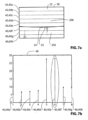
- the statistics engine 36 can divide a selected search window 38 (ie. a selected section of the image 25), into a plurality of vertically stacked bars 40 ( Figure 7a ), individually referred to at 40a-40h, or into a plurality of horizontally stacked bars 42 ( Figure 8 ) individually referred to at 42a-42h, and can output the sum of the greyscale values within each bar 40 or 42 to the camera microcontroller 18 ( Figure 5 ).
- the statistics engine 36 is configured to always break the search window 38 ( Figures 7a and 8 ) into 8 bars 40 ( Figure 7a ) or 42 ( Figure 8 ). It will be understood however, that in other embodiments, the statistics engine 36 ( Figure 5 ) may instead be configured to break the search window 38 into more or fewer bars 40 or 42.
- the search window 38 is divided into 8 vertically stacked bars 40 ( Figure 7a )
- the number of pixels (on the image sensor 16a) representing the height of the search window 38 is divisible by 8 so that each bar 40 is the same height (in terms of the number of pixels) and therefore contains the same number of pixels.
- the search window 38 is divided into 8 horizontally stacked bars 42 ( Figure 8 )
- the number of pixels (on the image sensor 16a) representing the width of the search window 38 is divisible by 8 so that each bar 42 is the same width and therefore contains the same number of pixels.
- the camera microcontroller 18 is capable of calibrating the camera 11 periodically using the statistical data provided by the imager microcontroller 16b. To calibrate the camera 11, the microcontroller 18 determines whether there is any horizontal or vertical offset in the images 25 by searching for a reference point in the images 25 and comparing its actual position to its expected position. Optionally, the microcontroller 18 may also determine whether there is any rotational offset in the images 25 by searching for a plurality of reference points in the images 25 and comparing their actual positions with their expected positions. The results of the comparisons can then be used to apply linear and optionally rotational adjustments to the positions of the overlays 26 in the images 25.
- the camera microcontroller 18 initially populates a database 110 with 50 (or some other selected number of) successful reference point detection cycles before an adjustment is made to the positions of the overlays 26, and any adjustments to the positions of the overlays 26 is made based on the offsets determined in the 50 successful cycles. As an example, adjustments to the positions of the overlays 26 may be made based on the median values of the 50 past successful cycles.
- a successful reference point detection cycle is a reference point detection cycle that is considered acceptable for addition to the database 110. Thereafter, with each new successful reference point detection cycle, the microcontroller 18 replaces the oldest record in the database 110 with the data from the new detection cycle. After each new successful detection cycle, the microcontroller 18 may adjust the positions of the overlays 26, not based solely on the offsets found in the current detection cycle, but based on the running history contained in the database 110.
- the camera microcontroller 18 contains several program modules including a calibration manager module 100, a pre-processing module 102, a linear offset detection module 104, a post-processing module 106 and an optional rotational offset detection module 108.
- the calibration manager module 100 determines whether the conditions are appropriate to conduct any reference point detection cycle and sends control to the pre-processing module 102 if the conditions are appropriate.
- the microcontroller 18 conducts reference point detection cycles on different driving days and at different driving times, with no more than one successful reference point detection cycle per day.
- reference point detection cycles are taken at selected time intervals regardless of the amount of mileage that has been accumulated by the vehicle 10.
- the calibration manager module 100 triggers a reference point detection cycle under the following conditions:
- the microcontroller 18 waits an additional selected period of time and then tries again to determine whether the conditions are met to trigger reference point detection cycle. If the vehicle 10 ( Figure 1 ) is not running after the additional selected period of time, the microcontroller 18 waits until the vehicle 10 is next turned on and checks if the conditions are met at that time. If the conditions are met, the microcontroller 18 calls the pre-processing module 102.
- the pre-processing module 102 assists in the selection of an exposure value to be used on images 25 received by the imager 16, and also determines whether the image 25 will have sufficient contrast to permit the structure on which the one or more reference points is present to be distinguished clearly from the background.
- the aforementioned structure is the vehicle bumper 202, and the background is shown at 206. If the pre-processing module 102 determines that the contrast is not sufficient in the image 25, then the reference point detection cycle is not run.
- the selection of the exposure to use on the images 25 is carried out by the imager microcontroller 16b based on a search window 203 ( Figure 16 ) that is selected by the camera microcontroller 18 ( Figure 5 ).
- the camera microcontroller 18 selects a search window 203 that includes both a portion of the vehicle bumper 202 and a portion of the background 206.
- the pre-processing module 102 determines if the contrast in the images 25 is likely to result in successful reference point detection cycles. As noted above, the imager 16 does not provide the image 25 itself to the microcontroller 18, but instead provides statistical information regarding a search window from the image 25. In order to determine whether the contrast is good, the pre-processing module 102 processes statistical data from a plurality of search windows shown in Figure 15 , including a plurality of first search windows 200 (shown individually at 200a, 200b and 200c) which are on the bumper 202, and a plurality of second search windows 204 (shown individually at 204a, 204b and 204c) which are on the background 206. Three search windows 200 and three search windows 204 are used in the embodiment shown, however it will be understood that a different number of search windows 200 and 204 may be used.
- the positions and sizes of the search windows 200 and 204 are selected so that even if the camera 11 ( Figure 2 ) is misaligned by some amount, there is a strong likelihood that the search windows 200 will be on the bumper 202 and that the search windows 204 will be on the background 206.
- the statistics engine 36 ( Figure 5 ) divides each first search window 200 ( Figure 15 ) into 8 horizontally stacked bars 208 and outputs the sum of the greyscale values of the pixels contained in each bar 208 to the microcontroller 18 ( Figure 5 ).
- the microcontroller 18 takes the 8 sums and calculates the mean and variance of this data.
- the statistics engine 36 divides each second search window 204 into 8 horizontally stacked bars 210 and outputs the sum of the greyscale values of the pixels contained in each bar 210 to the microcontroller 18.
- the microcontroller 18 calculates the mean and variance of the 8 sums. The microcontroller 18 then determines whether the differences in the mean values between any two of the three windows 200 are less than selected threshold values. The microcontroller 18 also determines whether the differences in the mean values between any two of the three windows 204 are less than selected threshold values. The microcontroller 18 also determines whether the difference in the mean values of each vertically adjacent pair of a window 200 and a window 204 is greater than a selected threshold value.
- the microcontroller 18 checks if the difference between the mean values of the windows 200a and 204a is greater than a selected value, and checks if the difference between the mean value of the windows 200b and 204b is greater than a selected value, and so on. Additionally, the microcontroller 18 also determines if the variance of each window 200 and 204 is less than a selected threshold value. If all of the above conditions are met, then the pre-processing module 102 permits an reference point detection cycle to be carried out. If any of these conditions are not met, then an reference point detection cycle is not carried out at that time.
- the pre-processing module 102 could be programmed to determine a suitable exposure to use for the images 25 received by the imager 16. In one example, the pre-processing module 102 could iteratively select exposures to use, refining each selection based on the results of the comparisons using the mean values and variances described above.
- the linear offset detection module 104 determines the position of a first reference point in the image 25.
- the reference point to search for depends on the position of the camera 11.
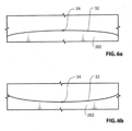
- the first reference point may be a point on the vehicle bumper 202.
- the edge of the bumper 202 is shown at 32.
- the bumper edge 32 appears curved due to distortion in the image 25.
- the curved bumper edge 32 has an extremum, which is shown at 34.
- the extremum 34 may also be referred to as the first reference point 34.
- the microcontroller 18 can determine the position of the extremum 34 ( Figures 6a, 6b ).
- the microcontroller 18 may first search for the vertical position of the first reference point 34, and may then search for the horizontal position of the first reference point 34.
- a search window 38 ( Figure 7a ) is selected by the microcontroller 18.
- the properties (ie. the size and position) of the search window 38 may initially be selected by the microcontroller 18 ( Figure 5 ) based on the estimated position of the first reference point 34.
- the search window 38 selected in the exemplary embodiment shown in Figure 7a is 240 pixels wide by 160 pixels high.
- the sums of the greyscale values of the vertically stacked bars 40 shown in Figure 7a are generated by the statistics engine 36 and sent to the microcontroller 18.
- the sums are represented mathematically as VAL(n), where n is the numerical position of the image bar 40 in the search window 38 (and is thus a value between 1 and 8 inclusive).
- the microcontroller 18 calculates the absolute values of gradients associated with the image bars 40 (referred to as absolute gradients).
- the absolute gradient at a particular image bar 40 is referred to as GRAD(n), where n is the numerical position of a particular image bar 40 in the search window 38.
- the absolute gradient GRAD(n) of the nth image bar is the absolute value of the sum of brightness values in the next image bar minus the sum of brightness values in the preceding image bar, all divided by 2. It will be understood that the formula above can be used for the second image bar 40b through to the seventh image bar 40g (ie. the second-to-last image bar).
- GRAD 1 ABS VAL 2 ⁇ VAL 1 _
- the absolute gradients GRAD(1) to GRAD(8) are shown graphically at 47 in the chart 48 shown in Figure 7b .
- the microcontroller 18 ( Figure 5 ) processes the absolute gradients to find the position of the image bar 40 ( Figure 7a ) having the largest associated gradient value.
- the absolute gradient 47f is the largest gradient, corresponding to the sixth image bar 40f.
- the position of the first reference point 34 may not necessarily be in the image bar 40 with the highest gradient. It could at least theoretically be in the image bar 40 up from that one (where the bumper edge 32 appears domed) or in the image bar down from that one (where the bumper edge 32 appears dished). In the image 25 shown in Figure 7a it does happen to be in the image bar 40 with the highest gradient however.
- the microcontroller 18 selects a second, narrower search window, shown at 49 in Figure 9a and divides it into 8 vertically stacked bars 50 (shown individually at 50a-50h).
- the position of the second search window 49 is selected based on which image bar 40 ( Figure 7a ) in the first search window 38 had the largest gradient (ie. the sixth image bar 40f in the example shown in the figures).
- the second search window 49 ( Figure 9a ) is preferably positioned to ensure capture of the first reference point 34 somewhere within the image bars 50b-50g.
- the microcontroller 18 positions the top of the second search window 49 the equivalent of the height of two image bars 40 from Figure 7a (ie.
- the second search window 49 is 64 pixels rows high, and so the second search window 49 extends 24 pixel rows below the bottom of the image bar 40f ( Figure 7a ).
- the absolute gradient calculations and analysis are performed on the second search window 49 to find which image bar 50 has the highest associated gradient.
- the resulting gradients are shown at 52 (and individually at 52a-52h), in the chart in Figure 9b .
- the absolute gradient shown at 52c is the highest in the chart in Figure 9b , and is associated with the image bar 50c in Figure 9a .
- the microcontroller 18 selects a third search window shown at 54 in Figure 10a , which is 240 pixels wide x 32 pixels high.
- the position of the third search window 54 is based on the position of the image bar 50c ( Figure 9a ).
- the position of the top of the third search window 54 is selected to be the equivalent of the height of two image bars 50 from Figure 9a (ie. 16 pixel rows) up from the bottom of the image bar 50b.
- the microcontroller 18 divides the third search window 54 ( Figure 10a ) into 8 vertically stacked image bars 55, (shown individually at 55a-55h), each of which is 4 pixels high, and performs the absolute gradient calculations thereon.
- the resulting gradient chart is shown at 56 in Figure 10b .
- the individual gradient shown at 57c, which is associated with the third image bar, shown at 58c in Figure 10a is the highest gradient in the chart.
- the microcontroller 18 selects a fourth search window 60 ( Figure 11a ), which is 240 pixels wide x 16 pixels high, based on the position of image bar 55c ( Figure 10a ).
- the microcontroller 18 divides the fourth search window 60 ( Figure 11a ) into 8 vertically stacked image bars 61, each of which is 2 pixels high, and performs the absolute gradient calculations on the fourth search window 60.
- the resulting gradient chart is shown at 62 in Figure 11b .
- the absolute gradient shown at 64e which is associated with the fifth image bar, shown at 61e in Figure 11a , is the highest gradient in the chart.
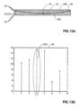
- the microcontroller 18 selects a fifth search window 66 ( Figure 12a ) which is 240 pixels wide x 8 pixels high, based on which image bar 61 ( Figure 11a ) had the largest gradient (ie. the fifth image bar 61e).
- the microcontroller 18 divides the fifth search window 66 into 8 vertically stacked image bars 67, each of which is 1 pixel high, and performs the absolute gradient calculations thereon.
- the resulting gradient chart is shown at 68 in Figure 12b .
- the vertical pixel position of the image bar 67d is determined by the microcontroller 18 to be the vertical pixel position of the first reference point 34.
- the microcontroller 18 selects a region of interest 70 ( Figure 13a ) and scans it for the presence of the bumper edge 32.
- the region of interest 70 may be about 240 pixels wide by 16 pixels high.
- the region of interest 70 is centered horizontally in the image 25. Vertically, the region of interest 70 extends from 12 pixels above the determined vertical position of the first reference point 34, to 4 pixels below the determined vertical position of the first reference point 34.
- the microcontroller 18 selects two first search windows 1000a and 1000b that are each 1 pixel wide x 8 pixels high, thereby forming a single compound search window that is 1 pixel wide x 16 pixels high.
- the microcontroller 18 obtains the greyscale values of each pixel in the two search windows 1000a and 1000b and determines which pixel out of the 16 pixels has the highest associated gradient. That pixel represents the bumper edge 32, and so the microcontroller 18 stores the position of that pixel in memory.
- the microcontroller 18 selects two second search windows 1008a and 1008b which are 8 pixels to the right of the first search windows 1000a and 1000b.
- the microcontroller 18 determines the greyscale values of each pixel in the two windows 1008a and 1008b and determines the pixel with the highest gradient among them and stores its position in memory. The microcontroller 18 then selects another pair of search windows 1016a and 1016b and determines the pixel with the highest gradient among them. The microcontroller 18 continues along the region of interest 70 selecting vertically stacked pairs of search windows at 8 pixel intervals.
- the chart shown in Figure 13b illustrates the pixel position values stored by the microcontroller 18 across 32 pairs of search windows.
- the pixel position values may be stored in a vector having a dimension of 1x32.
- the data contained in the vector may be conditioned and validated as follows, to account for problems that can arise, such as a change in the ambient environment seen by the camera 11 after the pre-processing module 102 ( Figure 5 ) has approved the cycle to proceed with detecting the reference point 34.
- the conditioning of the data in the vector takes place based on one or more rules that are applied to the data.
- a first rule is that the pixel position value of the first element in the vector, (ie. the pixel position value corresponding to the search windows 1000a and 1000b), cannot be larger than that of the second element in the vector (ie. cannot be larger than the pixel position value of the subsequent search windows 1008a and 1008b). If it is larger, its value is reduced to be the same as that of the second element.
- a second rule is that, if the pixel position value of any particular vector element (referred to as vector element (i) where i corresponds to its position in the vector) is less than that of the immediately preceding vector element (ie.
- a third rule is that if the pixel position value of any particular vector (ie. vector element (i)) is greater than that of vector element (i+1) and is greater than that of vector element (i-1), and if the pixel position value of vector element (i+1) is greater than that of vector element (i-1), then the pixel position value of vector element (i) is changed to match that of vector element (i+1).
- a fourth rule is similar to the third rule. If the pixel position value of any particular vector (ie. vector element (i)) is greater than that of vector element (i+1) and is greater than that of vector element (i-1), and if the pixel position value of vector element (i-1) is greater than that of vector element (i+1), then the pixel position value of vector element (i) is changed to match that of vector element (i-1).
- a fifth rule is that if the pixel position value of the last vector element, (ie. vector element (32)), is greater than that of the preceding vector element (ie. vector element (31)), then the value of the last vector element is changed to match that of the preceding vector element.
- a sixth rule is that if the highest pixel position value stored in the vector appears less than 4 times in the vector, then the pixel position values of the associated vector elements are changed to match the second highest pixel position value stored in the vector. It will be noted that the particular rules described above are based on knowledge a priori of what general shape the bumper 202 should have in the image 25. It will be noted that the aforementioned rules are intended as exemplary. It is alternatively possible for the system to apply a different set of rules to condition the values in the vector. It will be noted that the rules may change depending on the vehicle model on which the camera 11 is installed.
- the values are tested to determine if they are considered valid to determine whether the reference point detection can continue or whether to abandon the reference point detection cycle until some other time.
- the conditions checked to determine whether the values are valid may include one or more of the following 5 questions:
- any 'no' answer may be referred to as a glitch.
- a variable (which is given the name 'count1') stores the number of 'rising glitches' (ie. glitches where the pixel position value of vector element (i) > the pixel position value of the vector element (i+1)).
- a variable (which is given the name 'count2') stores the number of 'falling glitches' (ie. glitches where the pixel position value of vector element (i) ⁇ the pixel position value of the vector element (i+1)).
- a variable (which is given the name 'court3') stores the number of 'flat glitches' (glitches where the pixel position value of vector element (i) is not equal to highest pixel position value).
- the glitch amplitude corresponds to how far past the given limit the pixel position value was for any given vector element. If there are more than 3 glitches having a glitch amplitude of more than 3, then the reference point detection cycle is abandoned.
- the vector is passed through a 5 taps median filter.
- the filter goes through each vector element (i), and determines a median value for a group of 5 vector elements centered on element (i) (ie. the group of vector elements consisting of vector element (i-2), vector element (i-1), vector element (i), vector element (i+1) and vector element (i+2)).
- the filter then changes the value of the vector element (i) to the determined median value.
- the 5 taps median filter is an optional procedure. It is possible for the vector to be used as is without being passed through the filter. It is alternatively possible for the vector to be filtered in any other suitable way.
- the pixel position value (in this case a value of 14) is the same for the search window pairs 1096a, 1096b to 1160a, 1160b ( Figure 13a ), and so the actual horizontal position of the first reference point 34 is somewhere between them.
- the microcontroller 18 determines whether the same pixel position value (in this case a value of 14) is found for search window pairs 1095a, 1095b to 1089a, 1089b that are immediately to the left of the pair 1096a, 1096b, and for search window pairs 1161a, 1161b to 1167a, 1167b that are immediately to the right of the pair 1160a, 1160b.
- the same pixel position value in this case a value of 14
- the microcontroller 18 determines in the exemplary embodiment, that the pixel position value remains at 14 for all the search window pairs 1095a, 1095b to 1089a, 1089b.
- the microcontroller 18 determines that the pixel position value drops to 13 at the first search window pair 1161a, 1161b to the right of the window pair 1160a, 1160b. Accordingly, no further pixel position values are necessary to be determined to the right of that.
- the microcontroller 18 determines the middle (horizontally) between the leftmost search window pair and the rightmost search window pair that have the same peak pixel position value.
- the leftmost search window pair is shown at 1089a, 1089b
- the rightmost search window pair is shown at 1160a, 1160b.
- the two window pairs are 71 pixels apart horizontally.
- the middle of the peak is therefore 36 pixels to the right of search window pair 1089a, 1089b, and is determined by the microcontroller 18 to be the horizontal position of the first reference point 34.
- the above description provides one way of determining the vertical and horizontal positions of the first reference point 34. It is alternatively possible for the microcontroller 18 to determine the position of the first reference point 34 by any other suitable method, using the statistical data that is provided by the imager microcontroller 16b and without access to the image 25 itself.
- the algorithm itself may be different for different models of vehicle and different cameras, and for different locations for the camera. For example, certain portions of the algorithm may change depending on whether the vehicle bumper 202 appears dished or domed in images 25 taken by the camera 11. Also certain portions of the algorithm will change depending on the location of the camera 11 in the vehicle 10, since the particular structure on which the reference point is positioned and the associated background, changes depending on whether the camera 11 is side mounted camera or a rear mounted camera.
- the database 110 ( Figure 5 ) of calibration data is updated. These values are simply added to the database 110 if the database 110 isn't full. If the database 110 is already full, these values are used to overwrite the oldest reference point data contained in the database 110.
- the database 110 may be configured to hold data from 50 reference point detections cycles. Each record of the database 110 contains the horizontal and vertical pixel positions of the first reference point 34, the date and time and optionally other data. In total each record may take up 16 bytes of memory, including ten bytes for the horizontal and vertical pixel positions, the date and time, and 6 bytes for additional data. Thus, the total amount of memory required for 50 records is 800 bytes.
- the post-processing module 106 is used to determine whether or not to adjust the positions of the overlays 26 based on the database 110 of calibration data.
- the post-processing module 106 is itself made up of two modules including a statistics analysis module 300 and a decision logic module 302.
- the statistics analysis module 300 determines the mean values, the variance for the horizontal and vertical pixel positions in the database 110, the median of the pixel position data and the mode for the pixel position data, and the variance for the time of day data in the database 110.
- the decision logic module 106 determines whether or not to adjust the positions of the overlays 26.
- the actual adjustment that is made to the positions of the overlays 26 may be selected based on the entirety of the pixel position data in the database 110, not just on the currently determined pixel position values. It will be noted that the vertical and horizontal pixel positions of the overlays 26 are independent from one another. As such, it is possible that one coordinate (eg. the vertical position) of the overlays 26 may be adjusted, while the other coordinate (eg. the horizontal position) of the overlays 26 is not adjusted.
- the horizontal position used by the camera 11 for the overlays 26 will be updated.
- the vertical position used by the camera 11 for the overlays 26 will be updated.
- the microcontroller 18 determines that the amount of overall offset exceeds a selected amount, the microcontroller 18 notifies the vehicle driver that the camera 11 may be too far outside of its intended operating position and may require servicing. This can be especially useful in situations where the camera 11 has become seriously misaligned with the vehicle 10 or if the lens 20 has become significantly misaligned with the imager 16 due, for example, to a collision wherein damage to the camera 11 or vehicle tailgate has occurred and has gone unnoticed.
- the optional rotational offset detection module 108 detects if the camera 11 has any rotational offset so that this can be taken into account when adjusting the positions of the overlays 26.
- the curved line corresponding to the bumper's edge 32 ( Figure 17 ) in the image 25 would appear as shown at 400 in the rotation angle search window shown at 402 in Figure 17 , and would intersect with the side edges of the search window 402 at a height H1 on both the left and right sides.
- the curved line corresponding to the bumper's edge 32 appears skewed as shown at 404 and would intersect with the side edges of the search window 402 at different heights, as shown by H2a and H2b.
- the width of the search window 402 is shown at W.
- the rotation angle search window 402 may be selected based on the detected vertical position of the first reference point 34 ( Figure 7a ), and may extend a selected number of pixels above and below the vertical position of the first reference point 34, based on whether the bumper 202 appears domed or dished in the image 25 (this would be programmed into the module 108 during vehicle assembly).
- the width of the rotation angle search window 402 may be selected to ensure bumper edge 32 leaves the search window 402 at a point along the sides of the search window 402, and not on the top or bottom of the search window 402.
- the microcontroller 18 selects a first compound search window that is 1 pixel wide by 16 pixels high, and is thus made up of a pair of 1 pixel by 8 pixel search windows, along the left side of the search window 402.
- the pixel position representing the highest gradient in that compound search window is the pixel position at which the bumper edge leaves the left side of the search window 402.
- the microcontroller 18 selects a second compound search window on the right side of the search window 402 and determines the pixel with the highest associated gradient to determine the pixel position at which the bumper edge leaves the right side of the search window 402.
- the camera angle can be compared to historical data for the camera angle that is optionally contained in the database 110 and can be used to adjust the positions of the overlays 26.
- the rotation angle can affect the horizontal (and the vertical to a lesser extent) position of the extremum of the curve representing the bumper edge 32.
- a rotational change in the camera could cause the linear offset detection module 104 ( Figure 5 ) to find a horizontal shift in the camera's position.
- any contribution made by the rotation angle to the determined linear offset can be adjusted for.
- the camera 11 may be capable of being calibrated at night.
- the camera 11 may include a NIR (near infra-red) LED (shown at 11a in Figure 1 ) that is activated when the reference point detection and the camera angle detection are being carried out.
- the NIR LED 11a may have a narrow illumination pattern and may be directed generally towards the bumper's edge 32 ( Figure 1 ). The reflection from the bumper 202 will be stronger than the reflection from the background, thereby providing relatively high contrast at the bumper's edge 32.
- the calibration of the camera 11 can be carried out without the need to add any structure to the vehicle than is already present thereon (ie. without the need to add targets or other calibration-specific structure to the vehicle 10), and without the need for additional structure or modification to the camera 11 itself.
- the above-described camera 11 can be calibrated as described prior to the vehicle 10 leaving the assembly plant. Additionally or alternatively, the camera 11 can be calibrated when the vehicle 10 is at the dealer, prior to being sold or during a servicing of the vehicle 10. For example, a technician/service person at a vehicle dealer can send a signal to the camera 11 to enter a 'service mode' to facilitate its use in calibrating itself.
Landscapes
- Engineering & Computer Science (AREA)
- Physics & Mathematics (AREA)
- General Physics & Mathematics (AREA)
- Theoretical Computer Science (AREA)
- Mechanical Engineering (AREA)
- Computer Vision & Pattern Recognition (AREA)
- Studio Devices (AREA)
- Multimedia (AREA)
- Image Processing (AREA)
- Closed-Circuit Television Systems (AREA)
Claims (15)
- Système de vision pour véhicule, ledit système de vision comprenant :une caméra 11 ayant un objectif 20 et un imageur 16 ;dans lequel l'objectif 20 est positionné pour capturer une vue à l'extérieur d'un véhicule, et dans lequel, avec la caméra 11 installée sur le véhicule, la vue de la caméra 11 comporte une partie du véhicule ;dans lequel l'imageur 16 possède un micro dispositif de commande d'imageur et un capteur d'image qui est configuré pour recevoir des images de l'objectif 20, le micro dispositif de commande d'imageur ayant un moteur statistique générant des données statistiques à partir des images ;dans lequel la caméra comprend un micro dispositif de commande de caméra 18 utilisable pour commander l'application d'une superposition 26 aux images 25 ;un affichage embarqué 24 capable d'afficher des images capturées par l'imageur 16 ; etle micro dispositif de commande de caméra 18 peut fonctionner pour recevoir des données statistiques du micro dispositif de commande d'imageur de l'imageur 16 et le micro dispositif de commande de caméra 18 peut fonctionner pour détecter un point de référence 34 dans les images à l'aide des données statistiques et, en réponse à une détermination d'un décalage du point de référence 34 détecté par rapport à un emplacement attendu du point de référence 34, le micro dispositif de commande de caméra 18 peut être utilisé pour déterminer une quantité de décalage avec laquelle décaler la superposition sur les images 25 ; etcaractérisé par :dans lequel ledit micro dispositif de commande de caméra 18 peut fonctionner pour détecter des points de référence pendant des cycles de détection de points de référence et dans lequel lesdits cycles de détection de points de référence sont effectués lors de différents jours de conduite et à différents moments de conduite ; eten réponse au décalage déterminé, ledit micro dispositif de commande de caméra 18 décale la superposition 26 appliquée aux images affichées.
- Système de vision selon la revendication 1, dans lequel les images, sur lesquelles est appliquée la superposition 26, sont transmises à l'affichage embarqué 24 par le biais d'un signal analogique.
- Système de vision selon la revendication 1, dans lequel, avant de détecter le point de référence 34, le micro dispositif de commande de caméra 18 détermine s'il y a un contraste suffisant dans les images.
- Système de vision selon la revendication 3, dans lequel le micro dispositif de commande de caméra 18 sélectionne des barres de pixels dans les images et compare les valeurs de luminosité des pixels et les variations de luminosité entre pixels adjacents dans chaque barre pour déterminer s'il y a un contraste suffisant dans les images.
- Système de vision selon la revendication 1, dans lequel le micro dispositif de commande de caméra 18 peut fonctionner pour déterminer l'angle de rotation de la caméra 11 et pour ajuster la quantité de décalage sur la base au moins en partie de l'angle de rotation.
- Système de vision selon la revendication 5, dans lequel le micro dispositif de commande de caméra 18 peut fonctionner pour déterminer l'angle de rotation de la caméra 11 et pour ajuster la position de la superposition en rotation sur la base au moins en partie de l'angle de rotation détecté.
- Système de vision selon la revendication 1, comprenant en outre une diode électroluminescente proche infrarouge 11 utilisable pour émettre une lumière proche infrarouge sur la partie du véhicule.
- Système de vision selon la revendication 1, dans lequel le micro dispositif de commande de caméra 18 peut fonctionner pour recevoir des données de l'imageur 16 concernant des barres de pixels sur le capteur d'image.
- Système de vision selon la revendication 8, dans lequel le micro dispositif de commande de caméra 18 peut fonctionner pour détecter le point de référence de manière itérative à l'aide de données de l'imageur 16 relatives à des barres de pixels successivement plus petites sur le capteur d'image.
- Système de vision selon la revendication 8, dans lequel le micro dispositif de commande de caméra 18 peut fonctionner pour détecter la position verticale des pixels du point de référence à l'aide de données provenant de barres de pixels empilées verticalement sur le capteur d'image.
- Système de vision selon la revendication 10, dans lequel le micro dispositif de commande de caméra 18 peut fonctionner pour détecter la position horizontale des pixels du point de référence à l'aide de données provenant de barres de pixels empilées horizontalement sur le capteur d'image.
- Système de vision selon la revendication 1, dans lequel, avec la caméra 11 installée sur le véhicule, la vue de la caméra est vers l'arrière du véhicule.
- Système de vision selon la revendication 12, dans lequel, avec la caméra installée sur le véhicule, la vue de la caméra 11 comporte une partie du pare-chocs du véhicule.
- Système de vision selon la revendication 13, dans lequel, avec la caméra 11 installée sur le véhicule, le point de référence correspond à un point sur le bord du pare-chocs du véhicule.
- Système de vision selon la revendication 14, dans lequel le bord du pare-chocs du véhicule apparaît sous la forme d'une ligne courbe dans les images reçues par l'imageur et dans lequel le point de référence est un extremum sur la ligne courbe.
Applications Claiming Priority (2)
| Application Number | Priority Date | Filing Date | Title |
|---|---|---|---|
| US29461910P | 2010-01-13 | 2010-01-13 | |
| PCT/CA2011/000048 WO2011085489A1 (fr) | 2010-01-13 | 2011-01-13 | Caméra de véhicule et procédé d'étalonnage périodique de caméra de véhicule |
Publications (4)
| Publication Number | Publication Date |
|---|---|
| EP2523831A1 EP2523831A1 (fr) | 2012-11-21 |
| EP2523831A4 EP2523831A4 (fr) | 2013-11-06 |
| EP2523831B1 EP2523831B1 (fr) | 2015-12-16 |
| EP2523831B2 true EP2523831B2 (fr) | 2024-05-29 |
Family
ID=44303765
Family Applications (1)
| Application Number | Title | Priority Date | Filing Date |
|---|---|---|---|
| EP11732612.4A Active EP2523831B2 (fr) | 2010-01-13 | 2011-01-13 | Caméra de véhicule et procédé d'étalonnage périodique de caméra de véhicule |
Country Status (3)
| Country | Link |
|---|---|
| US (2) | US9150155B2 (fr) |
| EP (1) | EP2523831B2 (fr) |
| WO (1) | WO2011085489A1 (fr) |
Families Citing this family (72)
| Publication number | Priority date | Publication date | Assignee | Title |
|---|---|---|---|---|
| US20060061008A1 (en) | 2004-09-14 | 2006-03-23 | Lee Karner | Mounting assembly for vehicle interior mirror |
| US10144353B2 (en) | 2002-08-21 | 2018-12-04 | Magna Electronics Inc. | Multi-camera vision system for a vehicle |
| US7720580B2 (en) | 2004-12-23 | 2010-05-18 | Donnelly Corporation | Object detection system for vehicle |
| KR20090102789A (ko) | 2006-12-06 | 2009-09-30 | 퓨전 멀티시스템즈, 인크.(디비에이 퓨전-아이오) | 프로그레시브 raid를 이용한 데이터 저장 장치, 시스템 및 방법 |
| GB2447672B (en) | 2007-03-21 | 2011-12-14 | Ford Global Tech Llc | Vehicle manoeuvring aids |
| US8017898B2 (en) | 2007-08-17 | 2011-09-13 | Magna Electronics Inc. | Vehicular imaging system in an automatic headlamp control system |
| EP2523831B2 (fr) | 2010-01-13 | 2024-05-29 | Magna Electronics Inc. | Caméra de véhicule et procédé d'étalonnage périodique de caméra de véhicule |
| WO2011143628A2 (fr) | 2010-05-13 | 2011-11-17 | Fusion-Io, Inc. | Appareil, système et procédé pour opérations de stockage conditionnel et atomique |
| TWI465356B (zh) * | 2010-05-26 | 2014-12-21 | Hon Hai Prec Ind Co Ltd | 車用監測裝置及車用監測系統 |
| WO2012016089A2 (fr) | 2010-07-28 | 2012-02-02 | Fusion-Io, Inc. | Appareil, système et procédé d'opérations de stockage conditionnel et atomique |
| US9900522B2 (en) | 2010-12-01 | 2018-02-20 | Magna Electronics Inc. | System and method of establishing a multi-camera image using pixel remapping |
| US10196088B2 (en) | 2011-04-19 | 2019-02-05 | Ford Global Technologies, Llc | Target monitoring system and method |
| US9926008B2 (en) | 2011-04-19 | 2018-03-27 | Ford Global Technologies, Llc | Trailer backup assist system with waypoint selection |
| US9854209B2 (en) | 2011-04-19 | 2017-12-26 | Ford Global Technologies, Llc | Display system utilizing vehicle and trailer dynamics |
| US9723274B2 (en) * | 2011-04-19 | 2017-08-01 | Ford Global Technologies, Llc | System and method for adjusting an image capture setting |
| US9683848B2 (en) | 2011-04-19 | 2017-06-20 | Ford Global Technologies, Llc | System for determining hitch angle |
| US9555832B2 (en) | 2011-04-19 | 2017-01-31 | Ford Global Technologies, Llc | Display system utilizing vehicle and trailer dynamics |
| US9834153B2 (en) | 2011-04-25 | 2017-12-05 | Magna Electronics Inc. | Method and system for dynamically calibrating vehicular cameras |
| US9357208B2 (en) | 2011-04-25 | 2016-05-31 | Magna Electronics Inc. | Method and system for dynamically calibrating vehicular cameras |
| US10793067B2 (en) | 2011-07-26 | 2020-10-06 | Magna Electronics Inc. | Imaging system for vehicle |
| US9491450B2 (en) | 2011-08-01 | 2016-11-08 | Magna Electronic Inc. | Vehicle camera alignment system |
| DE102011112578A1 (de) * | 2011-09-08 | 2013-03-14 | Continental Teves Ag & Co. Ohg | Verfahren und Vorrichtung für ein Assistenzsystem in einem Fahrzeug zur Durchführung eines autonomen oder teilautonomen Fahrmanövers |
| US20140218535A1 (en) | 2011-09-21 | 2014-08-07 | Magna Electronics Inc. | Vehicle vision system using image data transmission and power supply via a coaxial cable |
| EP2581268B2 (fr) | 2011-10-13 | 2019-09-11 | Harman Becker Automotive Systems GmbH | Procédé de contrôle d'un dispositif à sortie optique pour afficher une visualisation panoramique de véhicule et système de visualisation panoramique de véhicule |
| WO2013074604A2 (fr) | 2011-11-15 | 2013-05-23 | Magna Electronics, Inc. | Système d'étalonnage et procédé pour système de vision panoramique de véhicule |
| US10099614B2 (en) | 2011-11-28 | 2018-10-16 | Magna Electronics Inc. | Vision system for vehicle |
| WO2013086249A2 (fr) | 2011-12-09 | 2013-06-13 | Magna Electronics, Inc. | Système de vision pour véhicule avec affichage personnalisé |
| EP2610778A1 (fr) * | 2011-12-27 | 2013-07-03 | Harman International (China) Holdings Co., Ltd. | Procédé pour la détection d'un obstacle et système d'aide au conducteur |
| WO2013126715A2 (fr) | 2012-02-22 | 2013-08-29 | Magna Electronics, Inc. | Système de caméra de véhicule à manipulation d'image |
| JP6025365B2 (ja) * | 2012-04-04 | 2016-11-16 | 京セラ株式会社 | 較正処理装置、カメラ較正装置、カメラシステム、およびカメラ較正方法 |
| US9723272B2 (en) | 2012-10-05 | 2017-08-01 | Magna Electronics Inc. | Multi-camera image stitching calibration system |
| US10179543B2 (en) | 2013-02-27 | 2019-01-15 | Magna Electronics Inc. | Multi-camera dynamic top view vision system |
| US9688200B2 (en) | 2013-03-04 | 2017-06-27 | Magna Electronics Inc. | Calibration system and method for multi-camera vision system |
| US9508014B2 (en) | 2013-05-06 | 2016-11-29 | Magna Electronics Inc. | Vehicular multi-camera vision system |
| US9563951B2 (en) | 2013-05-21 | 2017-02-07 | Magna Electronics Inc. | Vehicle vision system with targetless camera calibration |
| US9205776B2 (en) | 2013-05-21 | 2015-12-08 | Magna Electronics Inc. | Vehicle vision system using kinematic model of vehicle motion |
| EP3010761B1 (fr) | 2013-06-21 | 2019-07-24 | Magna Electronics Inc. | Système de vision de véhicule |
| WO2014206406A1 (fr) | 2013-06-26 | 2014-12-31 | Conti Temic Microelectronic Gmbh | Dispositif de remplacement de rétroviseur et véhicule |
| KR101510336B1 (ko) * | 2013-11-14 | 2015-04-07 | 현대자동차 주식회사 | 차량용 운전자 지원 시스템의 검사 장치 |
| US9464886B2 (en) | 2013-11-21 | 2016-10-11 | Ford Global Technologies, Llc | Luminescent hitch angle detection component |
| US9464887B2 (en) | 2013-11-21 | 2016-10-11 | Ford Global Technologies, Llc | Illuminated hitch angle detection component |
| KR101510338B1 (ko) * | 2013-11-22 | 2015-04-07 | 현대자동차 주식회사 | 차량용 차선 이탈 경보 시스템의 검사 장치 |
| US9487235B2 (en) | 2014-04-10 | 2016-11-08 | Magna Electronics Inc. | Vehicle control system with adaptive wheel angle correction |
| US20140232871A1 (en) * | 2014-05-01 | 2014-08-21 | Caterpillar Inc. | Method for manually calibrating a camera mounted on vehicle |
| US9986173B2 (en) * | 2014-05-16 | 2018-05-29 | GM Global Technology Operations LLC | Surround-view camera system (VPM) online calibration |
| US10525883B2 (en) | 2014-06-13 | 2020-01-07 | Magna Electronics Inc. | Vehicle vision system with panoramic view |
| US10112537B2 (en) | 2014-09-03 | 2018-10-30 | Ford Global Technologies, Llc | Trailer angle detection target fade warning |
| US11472338B2 (en) | 2014-09-15 | 2022-10-18 | Magna Electronics Inc. | Method for displaying reduced distortion video images via a vehicular vision system |
| US10127463B2 (en) | 2014-11-21 | 2018-11-13 | Magna Electronics Inc. | Vehicle vision system with multiple cameras |
| US9607242B2 (en) | 2015-01-16 | 2017-03-28 | Ford Global Technologies, Llc | Target monitoring system with lens cleaning device |
| US9916660B2 (en) | 2015-01-16 | 2018-03-13 | Magna Electronics Inc. | Vehicle vision system with calibration algorithm |
| US10946799B2 (en) * | 2015-04-21 | 2021-03-16 | Magna Electronics Inc. | Vehicle vision system with overlay calibration |
| US11228700B2 (en) | 2015-10-07 | 2022-01-18 | Magna Electronics Inc. | Vehicle vision system camera with adaptive field of view |
| US10187590B2 (en) | 2015-10-27 | 2019-01-22 | Magna Electronics Inc. | Multi-camera vehicle vision system with image gap fill |
| US9836060B2 (en) | 2015-10-28 | 2017-12-05 | Ford Global Technologies, Llc | Trailer backup assist system with target management |
| US11277558B2 (en) | 2016-02-01 | 2022-03-15 | Magna Electronics Inc. | Vehicle vision system with master-slave camera configuration |
| US11433809B2 (en) | 2016-02-02 | 2022-09-06 | Magna Electronics Inc. | Vehicle vision system with smart camera video output |
| JP6511406B2 (ja) * | 2016-02-10 | 2019-05-15 | クラリオン株式会社 | キャリブレーションシステム、キャリブレーション装置 |
| US10453217B2 (en) | 2016-03-24 | 2019-10-22 | Magna Electronics Inc. | Targetless vehicle camera calibration system |
| US10300859B2 (en) | 2016-06-10 | 2019-05-28 | Magna Electronics Inc. | Multi-sensor interior mirror device with image adjustment |
| US10380765B2 (en) | 2016-08-17 | 2019-08-13 | Magna Electronics Inc. | Vehicle vision system with camera calibration |
| US10504241B2 (en) | 2016-12-19 | 2019-12-10 | Magna Electronics Inc. | Vehicle camera calibration system |
| US10452076B2 (en) | 2017-01-04 | 2019-10-22 | Magna Electronics Inc. | Vehicle vision system with adjustable computation and data compression |
| TWI687094B (zh) * | 2017-02-08 | 2020-03-01 | 弗勞恩霍夫爾協會 | 使用模板匹配之預測式編碼概念技術 |
| US10710585B2 (en) | 2017-09-01 | 2020-07-14 | Ford Global Technologies, Llc | Trailer backup assist system with predictive hitch angle functionality |
| US10482626B2 (en) * | 2018-01-08 | 2019-11-19 | Mediatek Inc. | Around view monitoring systems for vehicle and calibration methods for calibrating image capture devices of an around view monitoring system using the same |
| EP3742192B1 (fr) * | 2018-09-28 | 2023-09-06 | NEXION S.p.A. | Système d'étalonnage d'une caméra de véhicule |
| US10664997B1 (en) * | 2018-12-04 | 2020-05-26 | Almotive Kft. | Method, camera system, computer program product and computer-readable medium for camera misalignment detection |
| US11410334B2 (en) | 2020-02-03 | 2022-08-09 | Magna Electronics Inc. | Vehicular vision system with camera calibration using calibration target |
| DE102020107016B4 (de) * | 2020-03-13 | 2024-06-20 | Mekra Lang Gmbh & Co. Kg | Verfahren zum Verifizieren eines indirekten Sichtsystems sowie indirektes Sichtsystem eines Fahrzeugs |
| JP7636113B2 (ja) * | 2021-04-13 | 2025-02-26 | アルプスアルパイン株式会社 | 映像表示システム |
| US20250356477A1 (en) * | 2024-05-15 | 2025-11-20 | Fca Us Llc | Vehicle content display verification |
Citations (4)
| Publication number | Priority date | Publication date | Assignee | Title |
|---|---|---|---|---|
| JP2005077107A (ja) † | 2003-08-29 | 2005-03-24 | Toyota Motor Corp | 車載カメラのキャリブレーション方法及びキャリブレーション装置 |
| EP1550982A2 (fr) † | 2003-12-19 | 2005-07-06 | Robert Bosch Gmbh | Dispositif de calibrage d'un système capteur d'images |
| US20060038895A1 (en) † | 2004-08-19 | 2006-02-23 | Nissan Motor, Co., Ltd. | Image processing device |
| US20090179916A1 (en) † | 2008-01-10 | 2009-07-16 | Williams Steven A | Method and apparatus for calibrating a video display overlay |
Family Cites Families (157)
| Publication number | Priority date | Publication date | Assignee | Title |
|---|---|---|---|---|
| US5845000A (en) | 1992-05-05 | 1998-12-01 | Automotive Technologies International, Inc. | Optical identification and monitoring system using pattern recognition for use with vehicles |
| US6735506B2 (en) | 1992-05-05 | 2004-05-11 | Automotive Technologies International, Inc. | Telematics system |
| JPS6021675A (ja) | 1983-07-18 | 1985-02-04 | Toyota Motor Corp | 計測機器におけるテレビカメラ位置ずれ自動補正方法及び装置 |
| US4794147A (en) | 1987-07-24 | 1988-12-27 | Basf Corporation, Inmont Division | Novel non-ionic polyurethane resins having polyether backbones in water-dilutable basecoats |
| JP2715442B2 (ja) | 1988-05-09 | 1998-02-18 | 株式会社デンソー | 走行車両認識装置 |
| JPH0397080A (ja) | 1989-09-11 | 1991-04-23 | Secom Co Ltd | 画像監視装置 |
| JPH03203000A (ja) | 1989-12-29 | 1991-09-04 | Matsushita Electric Ind Co Ltd | 道路標識自動認識装置 |
| JPH0397080U (fr) | 1990-01-25 | 1991-10-04 | ||
| WO1992002894A1 (fr) | 1990-07-27 | 1992-02-20 | Siemens Aktiengesellschaft | Procede d'analyse de sequences chronologiques d'images numeriques |
| US5469210A (en) | 1991-03-01 | 1995-11-21 | Canon Kabushiki Kaisha | Image pickup apparatus with control for output of non-vibrating images |
| JP2782990B2 (ja) | 1991-07-11 | 1998-08-06 | 日産自動車株式会社 | 車両用接近判定装置 |
| JPH0562099U (ja) | 1992-01-28 | 1993-08-13 | 関西日本電気株式会社 | 電子機器の収納チャンバ |
| US5521843A (en) | 1992-01-30 | 1996-05-28 | Fujitsu Limited | System for and method of recognizing and tracking target mark |
| US5627586A (en) | 1992-04-09 | 1997-05-06 | Olympus Optical Co., Ltd. | Moving body detection device of camera |
| US5523811A (en) | 1992-04-17 | 1996-06-04 | Canon Kabushiki Kaisha | Camera device for moving body |
| JPH05296767A (ja) | 1992-04-20 | 1993-11-09 | Mitsubishi Electric Corp | 車間距離検出装置 |
| GB2267341B (en) | 1992-05-27 | 1996-02-21 | Koito Mfg Co Ltd | Glare sensor for a vehicle |
| JPH0785280B2 (ja) | 1992-08-04 | 1995-09-13 | タカタ株式会社 | 神経回路網による衝突予測判定システム |
| EP0655150A4 (fr) | 1992-08-14 | 1996-06-05 | Vorad Safety Systems Inc | Enregistrement des evenements relatifs au fonctionnement d'un vehicule automoteur. |
| JPH0696397A (ja) | 1992-09-16 | 1994-04-08 | Mitsubishi Electric Corp | 画像追尾装置および画像追尾方法 |
| DE4332612C2 (de) | 1992-09-25 | 1996-02-22 | Yazaki Corp | Außenansichts-Überwachungsverfahren für Kraftfahrzeuge |
| IT1256956B (it) | 1992-10-05 | 1995-12-27 | Gilardini Spa | Dispositivo per rilevare posizioni relative tra veicoli, principalmente in funzione anticollisione. |
| US5448484A (en) | 1992-11-03 | 1995-09-05 | Bullock; Darcy M. | Neural network-based vehicle detection system and method |
| JPH06213660A (ja) | 1993-01-19 | 1994-08-05 | Aisin Seiki Co Ltd | 像の近似直線の検出方法 |
| US5877897A (en) | 1993-02-26 | 1999-03-02 | Donnelly Corporation | Automatic rearview mirror, vehicle lighting control and vehicle interior monitoring system using a photosensor array |
| US5550677A (en) | 1993-02-26 | 1996-08-27 | Donnelly Corporation | Automatic rearview mirror system using a photosensor array |
| US6498620B2 (en) | 1993-02-26 | 2002-12-24 | Donnelly Corporation | Vision system for a vehicle including an image capture device and a display system having a long focal length |
| US5796094A (en) | 1993-02-26 | 1998-08-18 | Donnelly Corporation | Vehicle headlight control using imaging sensor |
| US6396397B1 (en) | 1993-02-26 | 2002-05-28 | Donnelly Corporation | Vehicle imaging system with stereo imaging |
| US5670935A (en) | 1993-02-26 | 1997-09-23 | Donnelly Corporation | Rearview vision system for vehicle including panoramic view |
| JP2887039B2 (ja) | 1993-03-26 | 1999-04-26 | 三菱電機株式会社 | 車両周辺監視装置 |
| US5487116A (en) | 1993-05-25 | 1996-01-23 | Matsushita Electric Industrial Co., Ltd. | Vehicle recognition apparatus |
| US6553130B1 (en) | 1993-08-11 | 2003-04-22 | Jerome H. Lemelson | Motor vehicle warning and control system and method |
| US5586063A (en) | 1993-09-01 | 1996-12-17 | Hardin; Larry C. | Optical range and speed detection system |
| US5638116A (en) | 1993-09-08 | 1997-06-10 | Sumitomo Electric Industries, Ltd. | Object recognition apparatus and method |
| JP3205477B2 (ja) | 1994-02-17 | 2001-09-04 | 富士フイルムマイクロデバイス株式会社 | 車間距離検出装置 |
| US5537003A (en) | 1994-04-08 | 1996-07-16 | Gentex Corporation | Control system for automotive vehicle headlamps and other vehicle equipment |
| FR2718874B1 (fr) | 1994-04-15 | 1996-05-15 | Thomson Csf | Procédé de surveillance de trafic pour la détection automatique d'incident de véhicules. |
| US5668663A (en) | 1994-05-05 | 1997-09-16 | Donnelly Corporation | Electrochromic mirrors and devices |
| US7049945B2 (en) | 2000-05-08 | 2006-05-23 | Automotive Technologies International, Inc. | Vehicular blind spot identification and monitoring system |
| JP3287117B2 (ja) | 1994-07-05 | 2002-05-27 | 株式会社日立製作所 | 撮像装置を用いた車両用の環境認識装置 |
| JP3357749B2 (ja) | 1994-07-12 | 2002-12-16 | 本田技研工業株式会社 | 車両の走行路画像処理装置 |
| ES2185686T3 (es) | 1994-07-19 | 2003-05-01 | Donnelly Corp | Sistema de espejo retrovisor automatico con activacion automatica de los faros. |
| US5596365A (en) | 1995-01-13 | 1997-01-21 | The United States Of America As Represented By The Secretary Of The Army | Image stabilization apparatus for telescopic devices |
| US5642093A (en) | 1995-01-27 | 1997-06-24 | Fuji Jukogyo Kabushiki Kaisha | Warning system for vehicle |
| DE19507956C2 (de) | 1995-03-07 | 2002-11-07 | Daimler Chrysler Ag | Einrichtung zur Bestimmung des Fahrzeugabstandes von einer seitlichen Fahrbahnmarkierung |
| US5500766A (en) | 1995-05-04 | 1996-03-19 | Stonecypher; Bob | Blind spot side mirror |
| US5675489A (en) | 1995-07-06 | 1997-10-07 | Carnegie Mellon University | System and method for estimating lateral position |
| JPH0995194A (ja) | 1995-09-29 | 1997-04-08 | Aisin Seiki Co Ltd | 車両前方の物体検出装置 |
| FI100040B (fi) | 1995-11-02 | 1997-08-29 | Nokia Telecommunications Oy | Häiriösuojattu tehonsyöttömenetelmä ja tehonsyöttöjärjestely |
| JPH09142236A (ja) | 1995-11-17 | 1997-06-03 | Mitsubishi Electric Corp | 車両の周辺監視方法と周辺監視装置及び周辺監視装置の故障判定方法と周辺監視装置の故障判定装置 |
| JPH09150870A (ja) | 1995-11-27 | 1997-06-10 | Sogo Package Kk | ティシュペーパーカートン |
| JPH09150670A (ja) * | 1995-11-28 | 1997-06-10 | Sony Corp | 車後方確認システム |
| US6049619A (en) | 1996-02-12 | 2000-04-11 | Sarnoff Corporation | Method and apparatus for detecting moving objects in two- and three-dimensional scenes |
| US5786772A (en) | 1996-03-22 | 1998-07-28 | Donnelly Corporation | Vehicle blind spot detection display system |
| US5745310A (en) | 1996-03-25 | 1998-04-28 | Mathieu; Raymond J. | Method and apparatus for temporary view shifting of vehicle side mirror |
| JP3143063B2 (ja) | 1996-06-07 | 2001-03-07 | 株式会社日立製作所 | 移動体の走行制御装置 |
| US5796176A (en) | 1996-07-11 | 1998-08-18 | Donnelly Corporation | Memory mirror system for vehicles |
| US5798575A (en) | 1996-07-11 | 1998-08-25 | Donnelly Corporation | Vehicle mirror digital network and dynamically interactive mirror system |
| DE29621172U1 (de) | 1996-12-06 | 1998-04-09 | Hohe GmbH & Co. KG, 97903 Collenberg | Außenspiegel mit Sehwinkelerweiterung |
| US6587573B1 (en) | 2000-03-20 | 2003-07-01 | Gentex Corporation | System for controlling exterior vehicle lights |
| US5837994C1 (en) | 1997-04-02 | 2001-10-16 | Gentex Corp | Control system to automatically dim vehicle head lamps |
| JPH1166488A (ja) | 1997-08-21 | 1999-03-09 | Honda Motor Co Ltd | 白線認識装置 |
| US6250148B1 (en) | 1998-01-07 | 2001-06-26 | Donnelly Corporation | Rain sensor mount for use in a vehicle |
| JPH11144185A (ja) | 1997-09-03 | 1999-05-28 | Honda Motor Co Ltd | 自動運転制御誘導システム |
| US6313454B1 (en) | 1999-07-02 | 2001-11-06 | Donnelly Corporation | Rain sensor |
| KR100250323B1 (ko) | 1997-10-10 | 2000-04-01 | 정몽규 | 무인 자동차의 화상 처리 장치 및 방법 |
| WO1999023828A1 (fr) | 1997-10-30 | 1999-05-14 | Donnelly Corporation | Detecteur de pluie distinguant la pluie de la buee |
| DE19749086C1 (de) | 1997-11-06 | 1999-08-12 | Daimler Chrysler Ag | Vorrichtung zur Ermittlung fahrspurverlaufsindikativer Daten |
| US6201236B1 (en) | 1997-11-13 | 2001-03-13 | Auto Sense Ltd. | Detection system with improved noise tolerance |
| US6690268B2 (en) | 2000-03-02 | 2004-02-10 | Donnelly Corporation | Video mirror systems incorporating an accessory module |
| US6243003B1 (en) | 1999-08-25 | 2001-06-05 | Donnelly Corporation | Accessory module for vehicle |
| US6278377B1 (en) | 1999-08-25 | 2001-08-21 | Donnelly Corporation | Indicator for vehicle accessory |
| US6420975B1 (en) | 1999-08-25 | 2002-07-16 | Donnelly Corporation | Interior rearview mirror sound processing system |
| JPH11353565A (ja) | 1998-06-09 | 1999-12-24 | Yazaki Corp | 車両用衝突警報方法及び装置 |
| US6269308B1 (en) | 1998-08-20 | 2001-07-31 | Honda Giken Kogyo Kabushiki Kaisha | Safety running system for vehicle |
| US6201642B1 (en) | 1999-07-27 | 2001-03-13 | Donnelly Corporation | Vehicular vision system with a wide angle lens including a diffractive element |
| US6717610B1 (en) | 1998-11-25 | 2004-04-06 | Donnelly Corporation | Wide angle image capture system for vehicle |
| DE60009976T2 (de) | 1999-03-01 | 2004-09-02 | Yazaki Corp. | Rück- und Seitenblickmonitor mit Kamera für Fahrzeug |
| JP4287532B2 (ja) | 1999-03-01 | 2009-07-01 | 矢崎総業株式会社 | 車両用後側方監視装置 |
| US6226592B1 (en) | 1999-03-22 | 2001-05-01 | Veridian Erim International, Inc. | Method and apparatus for prompting a motor vehicle operator to remain within a lane |
| JP3853542B2 (ja) | 1999-07-26 | 2006-12-06 | パイオニア株式会社 | 画像処理装置、画像処理方法及びナビゲーション装置 |
| US6757109B2 (en) | 1999-07-27 | 2004-06-29 | Donnelly Corporation | Plastic lens system for vehicle imaging system |
| JP3632563B2 (ja) | 1999-10-19 | 2005-03-23 | 株式会社豊田自動織機 | 映像位置関係補正装置、該映像位置関係補正装置を備えた操舵支援装置、及び映像位置関係補正方法 |
| US6411204B1 (en) | 1999-11-15 | 2002-06-25 | Donnelly Corporation | Deceleration based anti-collision safety light control for vehicle |
| SE520360C2 (sv) | 1999-12-15 | 2003-07-01 | Goeran Sjoenell | Varningsanordning vid fordon |
| DE19962997B4 (de) | 1999-12-24 | 2010-06-02 | Robert Bosch Gmbh | Verfahren zur Kalibrierung eines Sensorsystems |
| US6813371B2 (en) | 1999-12-24 | 2004-11-02 | Aisin Seiki Kabushiki Kaisha | On-vehicle camera calibration device |
| JP3681052B2 (ja) | 2000-01-11 | 2005-08-10 | 三菱電機株式会社 | 追従走行制御装置 |
| JP2001213254A (ja) | 2000-01-31 | 2001-08-07 | Yazaki Corp | 車両用側方監視装置 |
| JP2001233150A (ja) | 2000-02-22 | 2001-08-28 | Yazaki Corp | 車両用危険判断装置及び、車両用周辺監視装置 |
| US7370983B2 (en) | 2000-03-02 | 2008-05-13 | Donnelly Corporation | Interior mirror assembly with display |
| KR100373002B1 (ko) | 2000-04-03 | 2003-02-25 | 현대자동차주식회사 | 차량의 차선 이탈 판단 방법 |
| US6671607B2 (en) | 2000-05-16 | 2003-12-30 | Nissan Motor Co., Ltd. | Vehicle speed control system |
| US6768509B1 (en) | 2000-06-12 | 2004-07-27 | Intel Corporation | Method and apparatus for determining points of interest on an image of a camera calibration object |
| US6760471B1 (en) | 2000-06-23 | 2004-07-06 | Teradyne, Inc. | Compensation system and related techniques for use in a printed circuit board inspection system |
| EP1309464B1 (fr) | 2000-08-16 | 2006-08-09 | Raytheon Company | Algorithme de distance de securite pour dispositif de reglage de vitesse adaptatif |
| JP3820342B2 (ja) * | 2000-08-31 | 2006-09-13 | 株式会社日立製作所 | 車載撮像装置 |
| JP3521860B2 (ja) | 2000-10-02 | 2004-04-26 | 日産自動車株式会社 | 車両の走行路認識装置 |
| EP1363810B1 (fr) | 2001-01-23 | 2007-05-30 | Donnelly Corporation | Systeme d'eclairage ameliore destine a un vehicule |
| US6708100B2 (en) | 2001-03-14 | 2004-03-16 | Raytheon Company | Safe distance algorithm for adaptive cruise control |
| DE10118265A1 (de) | 2001-04-12 | 2002-10-17 | Bosch Gmbh Robert | Verfahren zur Erkennung eines Spurwechsels eines Fahrzeugs |
| JP4713033B2 (ja) | 2001-06-29 | 2011-06-29 | 本田技研工業株式会社 | 車両周辺環境表示装置 |
| US6485155B1 (en) | 2001-07-06 | 2002-11-26 | Bernard Duroux | Multiplexing mirror |
| US6882287B2 (en) | 2001-07-31 | 2005-04-19 | Donnelly Corporation | Automotive lane change aid |
| JP2003154960A (ja) | 2001-09-04 | 2003-05-27 | Honda Motor Co Ltd | 車両の操舵制御装置 |
| JP4327389B2 (ja) | 2001-10-17 | 2009-09-09 | 株式会社日立製作所 | 走行レーン認識装置 |
| US7151844B2 (en) | 2001-12-06 | 2006-12-19 | General Motors Corporation | Image sensor method and apparatus having hardware implemented edge detection processing |
| US6824281B2 (en) | 2002-01-31 | 2004-11-30 | Donnelly Corporation | Vehicle accessory module |
| DE10207580A1 (de) | 2002-02-22 | 2003-09-11 | Bosch Gmbh Robert | Vorrichtung zur adaptiven Geschwindigkeitsregelung eines Kraftfahrzeugs |
| JP3891011B2 (ja) | 2002-03-12 | 2007-03-07 | 株式会社デンソー | クルーズ制御装置、プログラム |
| US7005974B2 (en) | 2002-04-19 | 2006-02-28 | Donnelly Corporation | Vehicle imaging system |
| US6946978B2 (en) | 2002-04-25 | 2005-09-20 | Donnelly Corporation | Imaging system for vehicle |
| US6968266B2 (en) | 2002-04-30 | 2005-11-22 | Ford Global Technologies, Llc | Object detection in adaptive cruise control |
| AU2003225228A1 (en) | 2002-05-03 | 2003-11-17 | Donnelly Corporation | Object detection system for vehicle |
| JP2003329439A (ja) | 2002-05-15 | 2003-11-19 | Honda Motor Co Ltd | 距離検出装置 |
| US6580996B1 (en) | 2002-08-07 | 2003-06-17 | Visteon Global Technologies, Inc. | Vehicle adaptive cruise control system and method |
| AU2003298558A1 (en) | 2002-08-21 | 2004-05-04 | Gentex Corporation | Image acquisition and processing methods for automatic vehicular exterior lighting control |
| US7965336B2 (en) * | 2002-11-14 | 2011-06-21 | Donnelly Corporation | Imaging system for vehicle |
| AU2003297394A1 (en) | 2002-12-20 | 2004-07-22 | Donnelly Corporation | Accessory system for vehicle |
| US7764808B2 (en) | 2003-03-24 | 2010-07-27 | Siemens Corporation | System and method for vehicle detection and tracking |
| EP1640215B1 (fr) | 2003-05-22 | 2007-03-07 | Fico Mirrors, S.A. | Ensemble de retroviseur exterieur de vehicule con u pour etre equipe d'un dispositif detecteur d'image |
| JP2005039599A (ja) | 2003-07-16 | 2005-02-10 | Nissan Motor Co Ltd | 車両周辺監視装置 |
| US7526103B2 (en) | 2004-04-15 | 2009-04-28 | Donnelly Corporation | Imaging system for vehicle |
| US8427538B2 (en) | 2004-04-30 | 2013-04-23 | Oncam Grandeye | Multiple view and multiple object processing in wide-angle video camera |
| US7420592B2 (en) | 2004-06-17 | 2008-09-02 | The Boeing Company | Image shifting apparatus for enhanced image resolution |
| US7881496B2 (en) | 2004-09-30 | 2011-02-01 | Donnelly Corporation | Vision system for vehicle |
| DE102004056669A1 (de) | 2004-10-13 | 2006-04-20 | Robert Bosch Gmbh | Einrichtung für die Kalibrierung eines Bildsensorsystems in einem Kraftfahrzeug |
| JP2006135621A (ja) * | 2004-11-05 | 2006-05-25 | Matsushita Electric Ind Co Ltd | カメラ校正装置 |
| DE102004062275A1 (de) | 2004-12-23 | 2006-07-13 | Aglaia Gmbh | Verfahren und Vorrichtung zum Ermitteln eines Kalibrierparameters einer Stereokamera |
| US7720580B2 (en) | 2004-12-23 | 2010-05-18 | Donnelly Corporation | Object detection system for vehicle |
| DE102005014954A1 (de) | 2005-04-01 | 2006-10-05 | Audi Ag | Korrektur der Messfehler des Gierwinkels bei Sensoren zur Fahrspurerkennung |
| IES20060800A2 (en) | 2005-10-28 | 2007-09-05 | Hi Key Ltd | A method and apparatus for calibrating an image capturing device, and a method and apparatus for outputting image frames from sequentially captured image frames with compensation for image capture device offset |
| US7388475B2 (en) | 2006-01-19 | 2008-06-17 | Gm Global Technology Operations, Inc. | Lane departure warning and avoidance system with warning modification criteria |
| JP2007256030A (ja) * | 2006-03-23 | 2007-10-04 | Clarion Co Ltd | 車載カメラのキャリブレーション装置およびキャリブレーション方法 |
| DE102006044615A1 (de) | 2006-09-19 | 2008-03-27 | Daimler Ag | Verfahren zur Kalibrierung von Bilderfassungseinrichtungen in Fahrzeugen |
| US8581983B2 (en) | 2007-03-07 | 2013-11-12 | Magna International Inc. | Vehicle interior classification system and method |
| US8017898B2 (en) | 2007-08-17 | 2011-09-13 | Magna Electronics Inc. | Vehicular imaging system in an automatic headlamp control system |
| WO2009036176A1 (fr) * | 2007-09-11 | 2009-03-19 | Magna Electronics | Système d'imagerie pour véhicule |
| DE102007043905A1 (de) | 2007-09-14 | 2008-05-29 | Daimler Ag | Verfahren und Vorrichtung zur Kalibrierung einer an einem Objekt angeordneten omnidirektionalen Kamera |
| JP2009212734A (ja) | 2008-03-04 | 2009-09-17 | Alpine Electronics Inc | 自動校正単眼ステレオ視装置 |
| US8373763B2 (en) | 2008-05-22 | 2013-02-12 | GM Global Technology Operations LLC | Self calibration of extrinsic camera parameters for a vehicle camera |
| JP2010073481A (ja) * | 2008-09-18 | 2010-04-02 | Alps Electric Co Ltd | 回転操作型入力装置 |
| EP2377094B1 (fr) | 2008-10-01 | 2014-06-11 | Connaught Electronics Limited | Procédé et système de calibration d un dispositif de capture d images |
| EP2179892A1 (fr) | 2008-10-24 | 2010-04-28 | Magna Electronics Europe GmbH & Co. KG | Procédé de calibrage automatique d'une caméra virtuelle |
| JP5328391B2 (ja) | 2009-01-29 | 2013-10-30 | トヨタ自動車株式会社 | 車載カメラ校正システム、車載カメラ制御装置、設備制御装置、車載カメラ校正方法 |
| JP4690476B2 (ja) | 2009-03-31 | 2011-06-01 | アイシン精機株式会社 | 車載カメラの校正装置 |
| EP2523831B2 (fr) | 2010-01-13 | 2024-05-29 | Magna Electronics Inc. | Caméra de véhicule et procédé d'étalonnage périodique de caméra de véhicule |
| US9357208B2 (en) | 2011-04-25 | 2016-05-31 | Magna Electronics Inc. | Method and system for dynamically calibrating vehicular cameras |
| WO2013074604A2 (fr) | 2011-11-15 | 2013-05-23 | Magna Electronics, Inc. | Système d'étalonnage et procédé pour système de vision panoramique de véhicule |
| WO2013086249A2 (fr) | 2011-12-09 | 2013-06-13 | Magna Electronics, Inc. | Système de vision pour véhicule avec affichage personnalisé |
| US20130286193A1 (en) | 2012-03-21 | 2013-10-31 | Magna Electronics Inc. | Vehicle vision system with object detection via top view superposition |
| US9723272B2 (en) | 2012-10-05 | 2017-08-01 | Magna Electronics Inc. | Multi-camera image stitching calibration system |
| US10179543B2 (en) | 2013-02-27 | 2019-01-15 | Magna Electronics Inc. | Multi-camera dynamic top view vision system |
| US9688200B2 (en) | 2013-03-04 | 2017-06-27 | Magna Electronics Inc. | Calibration system and method for multi-camera vision system |
| US9205776B2 (en) | 2013-05-21 | 2015-12-08 | Magna Electronics Inc. | Vehicle vision system using kinematic model of vehicle motion |
| US9563951B2 (en) | 2013-05-21 | 2017-02-07 | Magna Electronics Inc. | Vehicle vision system with targetless camera calibration |
-
2011
- 2011-01-13 EP EP11732612.4A patent/EP2523831B2/fr active Active
- 2011-01-13 US US13/521,872 patent/US9150155B2/en active Active
- 2011-01-13 WO PCT/CA2011/000048 patent/WO2011085489A1/fr not_active Ceased
-
2015
- 2015-10-05 US US14/874,999 patent/US9296337B2/en not_active Expired - Fee Related
Patent Citations (4)
| Publication number | Priority date | Publication date | Assignee | Title |
|---|---|---|---|---|
| JP2005077107A (ja) † | 2003-08-29 | 2005-03-24 | Toyota Motor Corp | 車載カメラのキャリブレーション方法及びキャリブレーション装置 |
| EP1550982A2 (fr) † | 2003-12-19 | 2005-07-06 | Robert Bosch Gmbh | Dispositif de calibrage d'un système capteur d'images |
| US20060038895A1 (en) † | 2004-08-19 | 2006-02-23 | Nissan Motor, Co., Ltd. | Image processing device |
| US20090179916A1 (en) † | 2008-01-10 | 2009-07-16 | Williams Steven A | Method and apparatus for calibrating a video display overlay |
Also Published As
| Publication number | Publication date |
|---|---|
| US20120320209A1 (en) | 2012-12-20 |
| WO2011085489A1 (fr) | 2011-07-21 |
| US20160023603A1 (en) | 2016-01-28 |
| EP2523831A1 (fr) | 2012-11-21 |
| US9150155B2 (en) | 2015-10-06 |
| EP2523831A4 (fr) | 2013-11-06 |
| US9296337B2 (en) | 2016-03-29 |
| EP2523831B1 (fr) | 2015-12-16 |
Similar Documents
| Publication | Publication Date | Title |
|---|---|---|
| EP2523831B1 (fr) | Caméra de véhicule et procédé d'étalonnage périodique de caméra de véhicule | |
| US11787338B2 (en) | Vehicular vision system | |
| JP7831772B2 (ja) | カメラ監視システムにおけるトレーラ端部のトラッキング | |
| US11270134B2 (en) | Method for estimating distance to an object via a vehicular vision system | |
| JP6458439B2 (ja) | 車載カメラ較正装置、画像生成装置、車載カメラ較正方法、画像生成方法 | |
| EP3431344B1 (fr) | Dispositif d'aide au stationnement, caméras embarquées, véhicule et procédé d'aide au stationnement | |
| US20130096820A1 (en) | Virtual display system for a vehicle | |
| US11535154B2 (en) | Method for calibrating a vehicular vision system | |
| US9697734B2 (en) | Information display device for vehicle and information display method for vehicle | |
| WO2013081984A1 (fr) | Système de vision pour véhicule | |
| JP5680436B2 (ja) | 車載カメラレンズ用異物付着判定装置 | |
| EP3439920B1 (fr) | Détermination d'orientations et/ou de positions de montage de plusieurs caméras d'un système de caméra de véhicule | |
| EP2351351A1 (fr) | Procédé et système de détection de la présence sur une lentille d'un dispositif de capture d'images d'une obstruction au passage de la lumière à travers la lentille du dispositif de capture d'images | |
| KR20170000363A (ko) | 차량, 특히 상용 차량을 위한 디스플레이 시스템 | |
| WO2015118806A1 (fr) | Appareil d'analyse d'image, et procédé d'analyse d'image | |
| TWI749030B (zh) | 駕駛輔助系統及駕駛輔助方法 | |
| EP2414776A1 (fr) | Appareil d'aide à la manipulation d'un véhicule | |
| EP2660795A2 (fr) | Système et procédé de surveillance d'un compresseur | |
| US20040189448A1 (en) | Video display for a vehicle environment surveillance unit | |
| US9308918B2 (en) | Object collision warning system and method for a motor vehicle | |
| JP4601376B2 (ja) | 画像異常判定装置 | |
| JP2008042759A (ja) | 画像処理装置 | |
| EP2385482B1 (fr) | Système d'assistance au conducteur et procédé pour véhicule à moteur |
Legal Events
| Date | Code | Title | Description |
|---|---|---|---|
| PUAI | Public reference made under article 153(3) epc to a published international application that has entered the european phase |
Free format text: ORIGINAL CODE: 0009012 |
|
| 17P | Request for examination filed |
Effective date: 20120813 |
|
| AK | Designated contracting states |
Kind code of ref document: A1 Designated state(s): AL AT BE BG CH CY CZ DE DK EE ES FI FR GB GR HR HU IE IS IT LI LT LU LV MC MK MT NL NO PL PT RO RS SE SI SK SM TR |
|
| DAX | Request for extension of the european patent (deleted) | ||
| A4 | Supplementary search report drawn up and despatched |
Effective date: 20131009 |
|
| RIC1 | Information provided on ipc code assigned before grant |
Ipc: B60R 11/04 20060101AFI20131002BHEP Ipc: H04N 7/18 20060101ALI20131002BHEP |
|
| 17Q | First examination report despatched |
Effective date: 20140723 |
|
| GRAP | Despatch of communication of intention to grant a patent |
Free format text: ORIGINAL CODE: EPIDOSNIGR1 |
|
| INTG | Intention to grant announced |
Effective date: 20150724 |
|
| GRAS | Grant fee paid |
Free format text: ORIGINAL CODE: EPIDOSNIGR3 |
|
| GRAA | (expected) grant |
Free format text: ORIGINAL CODE: 0009210 |
|
| AK | Designated contracting states |
Kind code of ref document: B1 Designated state(s): AL AT BE BG CH CY CZ DE DK EE ES FI FR GB GR HR HU IE IS IT LI LT LU LV MC MK MT NL NO PL PT RO RS SE SI SK SM TR |
|
| REG | Reference to a national code |
Ref country code: GB Ref legal event code: FG4D |
|
| REG | Reference to a national code |
Ref country code: CH Ref legal event code: EP |
|
| REG | Reference to a national code |
Ref country code: FR Ref legal event code: PLFP Year of fee payment: 6 |
|
| REG | Reference to a national code |
Ref country code: IE Ref legal event code: FG4D |
|
| REG | Reference to a national code |
Ref country code: AT Ref legal event code: REF Ref document number: 765407 Country of ref document: AT Kind code of ref document: T Effective date: 20160115 |
|
| REG | Reference to a national code |
Ref country code: DE Ref legal event code: R096 Ref document number: 602011022050 Country of ref document: DE |
|
| REG | Reference to a national code |
Ref country code: NL Ref legal event code: MP Effective date: 20151216 |
|
| REG | Reference to a national code |
Ref country code: LT Ref legal event code: MG4D |
|
| PG25 | Lapsed in a contracting state [announced via postgrant information from national office to epo] |
Ref country code: LT Free format text: LAPSE BECAUSE OF FAILURE TO SUBMIT A TRANSLATION OF THE DESCRIPTION OR TO PAY THE FEE WITHIN THE PRESCRIBED TIME-LIMIT Effective date: 20151216 Ref country code: HR Free format text: LAPSE BECAUSE OF FAILURE TO SUBMIT A TRANSLATION OF THE DESCRIPTION OR TO PAY THE FEE WITHIN THE PRESCRIBED TIME-LIMIT Effective date: 20151216 Ref country code: NO Free format text: LAPSE BECAUSE OF FAILURE TO SUBMIT A TRANSLATION OF THE DESCRIPTION OR TO PAY THE FEE WITHIN THE PRESCRIBED TIME-LIMIT Effective date: 20160316 |
|
| REG | Reference to a national code |
Ref country code: AT Ref legal event code: MK05 Ref document number: 765407 Country of ref document: AT Kind code of ref document: T Effective date: 20151216 |
|
| PG25 | Lapsed in a contracting state [announced via postgrant information from national office to epo] |
Ref country code: NL Free format text: LAPSE BECAUSE OF FAILURE TO SUBMIT A TRANSLATION OF THE DESCRIPTION OR TO PAY THE FEE WITHIN THE PRESCRIBED TIME-LIMIT Effective date: 20151216 Ref country code: GR Free format text: LAPSE BECAUSE OF FAILURE TO SUBMIT A TRANSLATION OF THE DESCRIPTION OR TO PAY THE FEE WITHIN THE PRESCRIBED TIME-LIMIT Effective date: 20160317 Ref country code: SE Free format text: LAPSE BECAUSE OF FAILURE TO SUBMIT A TRANSLATION OF THE DESCRIPTION OR TO PAY THE FEE WITHIN THE PRESCRIBED TIME-LIMIT Effective date: 20151216 Ref country code: BE Free format text: LAPSE BECAUSE OF NON-PAYMENT OF DUE FEES Effective date: 20160131 Ref country code: RS Free format text: LAPSE BECAUSE OF FAILURE TO SUBMIT A TRANSLATION OF THE DESCRIPTION OR TO PAY THE FEE WITHIN THE PRESCRIBED TIME-LIMIT Effective date: 20151216 Ref country code: FI Free format text: LAPSE BECAUSE OF FAILURE TO SUBMIT A TRANSLATION OF THE DESCRIPTION OR TO PAY THE FEE WITHIN THE PRESCRIBED TIME-LIMIT Effective date: 20151216 Ref country code: LV Free format text: LAPSE BECAUSE OF FAILURE TO SUBMIT A TRANSLATION OF THE DESCRIPTION OR TO PAY THE FEE WITHIN THE PRESCRIBED TIME-LIMIT Effective date: 20151216 |
|
| PG25 | Lapsed in a contracting state [announced via postgrant information from national office to epo] |
Ref country code: ES Free format text: LAPSE BECAUSE OF FAILURE TO SUBMIT A TRANSLATION OF THE DESCRIPTION OR TO PAY THE FEE WITHIN THE PRESCRIBED TIME-LIMIT Effective date: 20151216 Ref country code: CZ Free format text: LAPSE BECAUSE OF FAILURE TO SUBMIT A TRANSLATION OF THE DESCRIPTION OR TO PAY THE FEE WITHIN THE PRESCRIBED TIME-LIMIT Effective date: 20151216 Ref country code: IT Free format text: LAPSE BECAUSE OF FAILURE TO SUBMIT A TRANSLATION OF THE DESCRIPTION OR TO PAY THE FEE WITHIN THE PRESCRIBED TIME-LIMIT Effective date: 20151216 |
|
| PG25 | Lapsed in a contracting state [announced via postgrant information from national office to epo] |
Ref country code: LU Free format text: LAPSE BECAUSE OF FAILURE TO SUBMIT A TRANSLATION OF THE DESCRIPTION OR TO PAY THE FEE WITHIN THE PRESCRIBED TIME-LIMIT Effective date: 20160113 Ref country code: SK Free format text: LAPSE BECAUSE OF FAILURE TO SUBMIT A TRANSLATION OF THE DESCRIPTION OR TO PAY THE FEE WITHIN THE PRESCRIBED TIME-LIMIT Effective date: 20151216 Ref country code: AT Free format text: LAPSE BECAUSE OF FAILURE TO SUBMIT A TRANSLATION OF THE DESCRIPTION OR TO PAY THE FEE WITHIN THE PRESCRIBED TIME-LIMIT Effective date: 20151216 Ref country code: IS Free format text: LAPSE BECAUSE OF FAILURE TO SUBMIT A TRANSLATION OF THE DESCRIPTION OR TO PAY THE FEE WITHIN THE PRESCRIBED TIME-LIMIT Effective date: 20160416 Ref country code: RO Free format text: LAPSE BECAUSE OF FAILURE TO SUBMIT A TRANSLATION OF THE DESCRIPTION OR TO PAY THE FEE WITHIN THE PRESCRIBED TIME-LIMIT Effective date: 20151216 Ref country code: SM Free format text: LAPSE BECAUSE OF FAILURE TO SUBMIT A TRANSLATION OF THE DESCRIPTION OR TO PAY THE FEE WITHIN THE PRESCRIBED TIME-LIMIT Effective date: 20151216 Ref country code: EE Free format text: LAPSE BECAUSE OF FAILURE TO SUBMIT A TRANSLATION OF THE DESCRIPTION OR TO PAY THE FEE WITHIN THE PRESCRIBED TIME-LIMIT Effective date: 20151216 Ref country code: PT Free format text: LAPSE BECAUSE OF FAILURE TO SUBMIT A TRANSLATION OF THE DESCRIPTION OR TO PAY THE FEE WITHIN THE PRESCRIBED TIME-LIMIT Effective date: 20160418 |
|
| REG | Reference to a national code |
Ref country code: CH Ref legal event code: PL |
|
| REG | Reference to a national code |
Ref country code: DE Ref legal event code: R026 Ref document number: 602011022050 Country of ref document: DE |
|
| PLBI | Opposition filed |
Free format text: ORIGINAL CODE: 0009260 |
|
| PG25 | Lapsed in a contracting state [announced via postgrant information from national office to epo] |
Ref country code: MC Free format text: LAPSE BECAUSE OF FAILURE TO SUBMIT A TRANSLATION OF THE DESCRIPTION OR TO PAY THE FEE WITHIN THE PRESCRIBED TIME-LIMIT Effective date: 20151216 |
|
| PLAX | Notice of opposition and request to file observation + time limit sent |
Free format text: ORIGINAL CODE: EPIDOSNOBS2 |
|
| 26 | Opposition filed |
Opponent name: CONNAUGHT ELECTRONICS LTD. Effective date: 20160916 Opponent name: TRW SYSTEMS LIMITED Effective date: 20160916 |
|
| PG25 | Lapsed in a contracting state [announced via postgrant information from national office to epo] |
Ref country code: PL Free format text: LAPSE BECAUSE OF FAILURE TO SUBMIT A TRANSLATION OF THE DESCRIPTION OR TO PAY THE FEE WITHIN THE PRESCRIBED TIME-LIMIT Effective date: 20151216 Ref country code: CH Free format text: LAPSE BECAUSE OF NON-PAYMENT OF DUE FEES Effective date: 20160131 Ref country code: LI Free format text: LAPSE BECAUSE OF NON-PAYMENT OF DUE FEES Effective date: 20160131 Ref country code: DK Free format text: LAPSE BECAUSE OF FAILURE TO SUBMIT A TRANSLATION OF THE DESCRIPTION OR TO PAY THE FEE WITHIN THE PRESCRIBED TIME-LIMIT Effective date: 20151216 |
|
| REG | Reference to a national code |
Ref country code: IE Ref legal event code: MM4A |
|
| REG | Reference to a national code |
Ref country code: FR Ref legal event code: PLFP Year of fee payment: 7 |
|
| PG25 | Lapsed in a contracting state [announced via postgrant information from national office to epo] |
Ref country code: BE Free format text: LAPSE BECAUSE OF FAILURE TO SUBMIT A TRANSLATION OF THE DESCRIPTION OR TO PAY THE FEE WITHIN THE PRESCRIBED TIME-LIMIT Effective date: 20151216 |
|
| PG25 | Lapsed in a contracting state [announced via postgrant information from national office to epo] |
Ref country code: IE Free format text: LAPSE BECAUSE OF NON-PAYMENT OF DUE FEES Effective date: 20160113 |
|
| PG25 | Lapsed in a contracting state [announced via postgrant information from national office to epo] |
Ref country code: SI Free format text: LAPSE BECAUSE OF FAILURE TO SUBMIT A TRANSLATION OF THE DESCRIPTION OR TO PAY THE FEE WITHIN THE PRESCRIBED TIME-LIMIT Effective date: 20151216 |
|
| PLBB | Reply of patent proprietor to notice(s) of opposition received |
Free format text: ORIGINAL CODE: EPIDOSNOBS3 |
|
| REG | Reference to a national code |
Ref country code: DE Ref legal event code: R082 Ref document number: 602011022050 Country of ref document: DE Representative=s name: SCHMITT-NILSON SCHRAUD WAIBEL WOHLFROM PATENTA, DE |
|
| PG25 | Lapsed in a contracting state [announced via postgrant information from national office to epo] |
Ref country code: MT Free format text: LAPSE BECAUSE OF FAILURE TO SUBMIT A TRANSLATION OF THE DESCRIPTION OR TO PAY THE FEE WITHIN THE PRESCRIBED TIME-LIMIT Effective date: 20151216 |
|
| REG | Reference to a national code |
Ref country code: FR Ref legal event code: PLFP Year of fee payment: 8 |
|
| PLAB | Opposition data, opponent's data or that of the opponent's representative modified |
Free format text: ORIGINAL CODE: 0009299OPPO |
|
| PG25 | Lapsed in a contracting state [announced via postgrant information from national office to epo] |
Ref country code: HU Free format text: LAPSE BECAUSE OF FAILURE TO SUBMIT A TRANSLATION OF THE DESCRIPTION OR TO PAY THE FEE WITHIN THE PRESCRIBED TIME-LIMIT; INVALID AB INITIO Effective date: 20110113 Ref country code: CY Free format text: LAPSE BECAUSE OF FAILURE TO SUBMIT A TRANSLATION OF THE DESCRIPTION OR TO PAY THE FEE WITHIN THE PRESCRIBED TIME-LIMIT Effective date: 20151216 |
|
| R26 | Opposition filed (corrected) |
Opponent name: TRW SYSTEMS LIMITED Effective date: 20160916 |
|
| PG25 | Lapsed in a contracting state [announced via postgrant information from national office to epo] |
Ref country code: MT Free format text: LAPSE BECAUSE OF FAILURE TO SUBMIT A TRANSLATION OF THE DESCRIPTION OR TO PAY THE FEE WITHIN THE PRESCRIBED TIME-LIMIT Effective date: 20160131 Ref country code: MK Free format text: LAPSE BECAUSE OF FAILURE TO SUBMIT A TRANSLATION OF THE DESCRIPTION OR TO PAY THE FEE WITHIN THE PRESCRIBED TIME-LIMIT Effective date: 20151216 Ref country code: TR Free format text: LAPSE BECAUSE OF FAILURE TO SUBMIT A TRANSLATION OF THE DESCRIPTION OR TO PAY THE FEE WITHIN THE PRESCRIBED TIME-LIMIT Effective date: 20151216 |
|
| PG25 | Lapsed in a contracting state [announced via postgrant information from national office to epo] |
Ref country code: BG Free format text: LAPSE BECAUSE OF FAILURE TO SUBMIT A TRANSLATION OF THE DESCRIPTION OR TO PAY THE FEE WITHIN THE PRESCRIBED TIME-LIMIT Effective date: 20151216 |
|
| APAH | Appeal reference modified |
Free format text: ORIGINAL CODE: EPIDOSCREFNO |
|
| APBM | Appeal reference recorded |
Free format text: ORIGINAL CODE: EPIDOSNREFNO |
|
| APBP | Date of receipt of notice of appeal recorded |
Free format text: ORIGINAL CODE: EPIDOSNNOA2O |
|
| PG25 | Lapsed in a contracting state [announced via postgrant information from national office to epo] |
Ref country code: AL Free format text: LAPSE BECAUSE OF FAILURE TO SUBMIT A TRANSLATION OF THE DESCRIPTION OR TO PAY THE FEE WITHIN THE PRESCRIBED TIME-LIMIT Effective date: 20151216 |
|
| APBM | Appeal reference recorded |
Free format text: ORIGINAL CODE: EPIDOSNREFNO |
|
| APBP | Date of receipt of notice of appeal recorded |
Free format text: ORIGINAL CODE: EPIDOSNNOA2O |
|
| APBQ | Date of receipt of statement of grounds of appeal recorded |
Free format text: ORIGINAL CODE: EPIDOSNNOA3O |
|
| APBU | Appeal procedure closed |
Free format text: ORIGINAL CODE: EPIDOSNNOA9O |
|
| PLAY | Examination report in opposition despatched + time limit |
Free format text: ORIGINAL CODE: EPIDOSNORE2 |
|
| PLBC | Reply to examination report in opposition received |
Free format text: ORIGINAL CODE: EPIDOSNORE3 |
|
| PLAY | Examination report in opposition despatched + time limit |
Free format text: ORIGINAL CODE: EPIDOSNORE2 |
|
| P01 | Opt-out of the competence of the unified patent court (upc) registered |
Effective date: 20230509 |
|
| PGFP | Annual fee paid to national office [announced via postgrant information from national office to epo] |
Ref country code: GB Payment date: 20231130 Year of fee payment: 14 |
|
| PGFP | Annual fee paid to national office [announced via postgrant information from national office to epo] |
Ref country code: FR Payment date: 20231212 Year of fee payment: 14 |
|
| PUAH | Patent maintained in amended form |
Free format text: ORIGINAL CODE: 0009272 |
|
| STAA | Information on the status of an ep patent application or granted ep patent |
Free format text: STATUS: PATENT MAINTAINED AS AMENDED |
|
| 27A | Patent maintained in amended form |
Effective date: 20240529 |
|
| AK | Designated contracting states |
Kind code of ref document: B2 Designated state(s): AL AT BE BG CH CY CZ DE DK EE ES FI FR GB GR HR HU IE IS IT LI LT LU LV MC MK MT NL NO PL PT RO RS SE SI SK SM TR |
|
| REG | Reference to a national code |
Ref country code: DE Ref legal event code: R102 Ref document number: 602011022050 Country of ref document: DE |
|
| PGFP | Annual fee paid to national office [announced via postgrant information from national office to epo] |
Ref country code: DE Payment date: 20241203 Year of fee payment: 15 |
|
| GBPC | Gb: european patent ceased through non-payment of renewal fee |
Effective date: 20250113 |
|
| PG25 | Lapsed in a contracting state [announced via postgrant information from national office to epo] |
Ref country code: GB Free format text: LAPSE BECAUSE OF NON-PAYMENT OF DUE FEES Effective date: 20250113 |
|
| PG25 | Lapsed in a contracting state [announced via postgrant information from national office to epo] |
Ref country code: FR Free format text: LAPSE BECAUSE OF NON-PAYMENT OF DUE FEES Effective date: 20250131 |