EP2576079B1 - Düsenkopf für eine spritzvorrichtung - Google Patents
Düsenkopf für eine spritzvorrichtung Download PDFInfo
- Publication number
- EP2576079B1 EP2576079B1 EP11723182.9A EP11723182A EP2576079B1 EP 2576079 B1 EP2576079 B1 EP 2576079B1 EP 11723182 A EP11723182 A EP 11723182A EP 2576079 B1 EP2576079 B1 EP 2576079B1
- Authority
- EP
- European Patent Office
- Prior art keywords
- nozzle
- nozzle head
- air
- head according
- horn
- Prior art date
- Legal status (The legal status is an assumption and is not a legal conclusion. Google has not performed a legal analysis and makes no representation as to the accuracy of the status listed.)
- Active
Links
Images




Classifications
-
- B—PERFORMING OPERATIONS; TRANSPORTING
- B05—SPRAYING OR ATOMISING IN GENERAL; APPLYING FLUENT MATERIALS TO SURFACES, IN GENERAL
- B05B—SPRAYING APPARATUS; ATOMISING APPARATUS; NOZZLES
- B05B7/00—Spraying apparatus for discharge of liquids or other fluent materials from two or more sources, e.g. of liquid and air, of powder and gas
- B05B7/02—Spray pistols; Apparatus for discharge
- B05B7/06—Spray pistols; Apparatus for discharge with at least one outlet orifice surrounding another approximately in the same plane
- B05B7/062—Spray pistols; Apparatus for discharge with at least one outlet orifice surrounding another approximately in the same plane with only one liquid outlet and at least one gas outlet
- B05B7/063—Spray pistols; Apparatus for discharge with at least one outlet orifice surrounding another approximately in the same plane with only one liquid outlet and at least one gas outlet one fluid being sucked by the other
- B05B7/064—Spray pistols; Apparatus for discharge with at least one outlet orifice surrounding another approximately in the same plane with only one liquid outlet and at least one gas outlet one fluid being sucked by the other the liquid being sucked by the gas
-
- B—PERFORMING OPERATIONS; TRANSPORTING
- B05—SPRAYING OR ATOMISING IN GENERAL; APPLYING FLUENT MATERIALS TO SURFACES, IN GENERAL
- B05B—SPRAYING APPARATUS; ATOMISING APPARATUS; NOZZLES
- B05B7/00—Spraying apparatus for discharge of liquids or other fluent materials from two or more sources, e.g. of liquid and air, of powder and gas
- B05B7/02—Spray pistols; Apparatus for discharge
- B05B7/08—Spray pistols; Apparatus for discharge with separate outlet orifices, e.g. to form parallel jets, i.e. the axis of the jets being parallel, to form intersecting jets, i.e. the axis of the jets converging but not necessarily intersecting at a point
- B05B7/0807—Spray pistols; Apparatus for discharge with separate outlet orifices, e.g. to form parallel jets, i.e. the axis of the jets being parallel, to form intersecting jets, i.e. the axis of the jets converging but not necessarily intersecting at a point to form intersecting jets
- B05B7/0815—Spray pistols; Apparatus for discharge with separate outlet orifices, e.g. to form parallel jets, i.e. the axis of the jets being parallel, to form intersecting jets, i.e. the axis of the jets converging but not necessarily intersecting at a point to form intersecting jets with at least one gas jet intersecting a jet constituted by a liquid or a mixture containing a liquid for controlling the shape of the latter
-
- B—PERFORMING OPERATIONS; TRANSPORTING
- B05—SPRAYING OR ATOMISING IN GENERAL; APPLYING FLUENT MATERIALS TO SURFACES, IN GENERAL
- B05B—SPRAYING APPARATUS; ATOMISING APPARATUS; NOZZLES
- B05B7/00—Spraying apparatus for discharge of liquids or other fluent materials from two or more sources, e.g. of liquid and air, of powder and gas
- B05B7/02—Spray pistols; Apparatus for discharge
- B05B7/025—Nozzles having elongated outlets, e.g. slots, for the material to be sprayed
Definitions
- the invention relates to a nozzle head for a spray device according to the preamble of claim 1.
- Such nozzle heads are common to spray devices for hydrostatic, pneumatic or combined hydrostatic and pneumatic atomization of paint, paint, glue or other liquid substances, in particular paint spray guns.
- the air ring nozzle has the function of allowing the compressed air supplied to the device to emerge as an air jet of high energy, which sucks material from another, central nozzle, atomized and forms a material-laden spray jet.
- Horned air nozzles are usually directed obliquely and in the same direction to the outflow direction on the spray jet in laterally arranged, in the direction of spray jet pointing horns of the nozzle head, so that the air jets emerging from these nozzles can deform or shape the spray jet.
- a more or less large flat jet or a flat and omnidirectional jet is produced as a function of the flow energy (amount of air, air pressure, flow velocity, etc.).
- the spray jet In order to achieve an optimum result, the spray jet must be adjusted for the beam width, material distribution, material type and drop size, among other things.
- the adaptation is carried out depending on the physical boundary conditions (input air pressure, air volume, etc.) essentially by constructive adjustment of the mouth of the central air ring nozzle and the Horn Kunststoffdüsen.
- the Horn Kunststoffdüsen For sufficiently homogeneous spray steels usually one, two, three or more horn air nozzles are used per horn, which interact with the central mouth of the central nozzle. From practice paint spray guns with one, two or more Hornluftdüsen are known, which ensure sufficient beam shaping and atomization on the criteria of mutual distance, diameter, angle and distance to the paint nozzle mouth, and their number.
- the Horn Kunststoffdüsen are provided in an air cap attached to the spray gun body, is usually screwed by means of fastening rings.
- the central air nozzle can also be screwed directly onto the paint nozzle or on the paint spray gun body, clipped or be otherwise attached.
- Such a nozzle head is known for example from German Utility Model G 90 01 265.8.
- the color nozzle openings and the Hornluftdüsenö réelleen are designed as commonly used as round holes.
- the diameters of the Hornfuftdüsen be made different sizes depending on the inlet pressure and the individually desired shape of the spray jet.
- the effect of the individual horn air nozzles depends on the inlet pressure. At higher input pressures, the beam may split. If the input pressures are too low, unwanted coarsening with small beam width may occur. There is also a large dependence of material throughput and other material properties (e.g., viscosity, rheology, etc.), inlet pressure, and horn air nozzle placement. Occasionally, with the use of one or more smaller horn air nozzles or unfavorable bore angles, problems arise with back mist on the mouth surfaces of the nozzles due to the suction effect at smaller nozzle or bore diameters.
- a modified version of a spray gun with a nozzle head shows the patent US 5,165,605 wherein the nozzle head laterally protruding horns with slot-shaped Hornauslassö Stammen describes.
- a major drawback of this method of beam shaping is that much of the energy used for beam forming and post-atomization already evaporates through the tight holes and multiple outlets to the ambient air (large shear surfaces at the surface in connection with large speed differences).
- modified nozzle heads with possibly different spraying parameters and geometries have to be used for slightly different color or paint materials in order to achieve a perfect spray pattern and thus the desired color, lacquer or to get other material order result.
- the object of the invention is to improve a nozzle head so that the flow energy of the compressed air can be optimally implemented in Strahiformung, flow rate and thus in Zerstäubungsaille.
- a nozzle head having the features of claim 1.
- the invention is based on the fact that in cylindrical nozzles the necessary adaptation to the individual requirements is possible only by variations in the diameter dimensions, the length and the inclination of the cylindrical bores, their mutual distance and the distance to the other nozzle openings.
- Non-cylindrical nozzles can be more easily optimized in terms of flow and adapted to the individual task.
- the inner shape, in particular the mouth of the nozzle should be non-cylindrical.
- the outer shape of the nozzles is usually negligible for beam forming.
- the round jet can be preformed by a special shaping so that less horn air is required for the shaping of the broad jet and any desired beam shapes can be achieved.
- elliptical or at least approximately slot-shaped nozzles are recommended in cross-section.
- grooves, slats, air vanes or the like may be provided for air conduction in the nozzle openings.
- the non-cylindrical nozzles can be made in metal parts by machining.
- the non-cylindrical nozzles made of plastic, in particular of an injection-moldable plastic, can be produced in a particularly simple manner. It is also possible to use such nozzles in plastic inserts and fasten in metal nozzle heads.
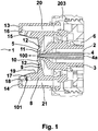
- the in Fig. 1 and 2 Exemplary nozzle head for a paint spray gun has a paint nozzle body 1 with a substantially cylindrical ink channel 2, which opens centrally in a paint nozzle 3.
- a hollow paint needle 4 is inserted in the paint nozzle 3.
- the paint nozzle 3 is surrounded by an air ring nozzle 5, the air can be supplied via channels 6.
- an air cap 7 On the gun body, an air cap 7 by means of a ring 203, which is commonly referred to as air nozzle ring, screwed.
- the air cap 7 could also be otherwise attached to the gun body.
- the air cap 7 is injection-molded from a plastic. It has an annular portion 8 which fits fittingly on the gun body.
- the annular section 8 is followed by a substantially flat cover plate 9.
- the cover plate 9 has an over this flat region 9 projecting annular elevation 10, in which an opening 11 is recessed centrally.
- the cover plate 9 are provided laterally the opening 11 at several points continuous control nozzles or control openings 12.
- the control nozzle openings 12 are aligned at an angle of about 20 degrees to the spray jet direction 100 out.
- the air cap 7 has a respective horn 13 or 14, which extends forward in the spray direction 100.
- the horns 13, 14 are formed as rectangular in cross section, closed at the top body.
- Each horn 13, 14 has two jet air nozzles 15, 16 or 17, 18 which are arranged one behind the other in the direction of spray jet 100 and extend through the inner wall 19 of the horns 13, 14.
- the Horn povertydüsen 15,16,17,18 are aligned obliquely in the direction of the spray jet 100.
- the two Hornluftdüsen 15, 16 and 17, 18 of each horn 13 and 14 are substantially parallel to each other at an angle 101 of about 140 degrees to the spray direction 100.
- the Hornluftdüsen 15, 16 but could also at an angle to each other or against each other. They can be supplied with compressed air in each case via an air duct 20 or 21 extending in the longitudinal direction through the horn 13 or 14.
- the ring air jet emerging with high energy from the air ring nozzle 5 sucks the paint out of the paint nozzle 3, forming an omnidirectional jet which flows off in the spray jet direction 100.
- the horn air jets emerging from the horn air nozzles 15, 16 or 17, 18 are directed onto the round jet and flow obliquely and in the same direction to the spray jet direction 100 and deform the round jet to the desired broad jet.
- the Hornluftdüsen 15, 16 and 17, 18 are fluidically optimized so that the circular beam undergoes a homogeneous beam shaping and the desired beam width is achieved without splitting the spray jet.
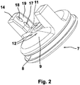
- Fig. 2 shows a not claimed embodiment, both Hornluftdüsen 17, 18 of the horn 14 are elliptical in cross section and the same big educated.
- the narrow curves of the ellipses are up or down.
- the ellipses could also be arranged transversely to the longitudinal extension of the horn 14 or 13. Combinations of such ellipses are also possible.
- This special design of the Hornluftdüsen 17, 18 could be easily realized by injection molding the air cap 7. It is not absolutely necessary to provide a separate air cap 7; the nozzle head 1 could also be designed differently (in one piece).
- Essential in the context of the invention are the non-cylindrical nozzles in the nozzle head.
- the paint needle 4 is hollow and has a cylindrical opening 4a along its longitudinal axis, through which a vacuum or an overpressure in the spray jet can be generated.
- a further paint component is injected into the spray jet via the hollow needle 4.
- the inlet opening of the needle 4 is connected to corresponding material-containing devices.
- the opening 4a may be non-cylindrical, e.g. be oval in cross section or in any other non-cylindrical shape.
- the opening 4a may be connected to compressed air or vacuum.
- the color needle 4 could not be hollow, but formed of solid body.
- the needle 4 is advantageously always designed so that its outer shape at the sealing point or contact surface on the paint nozzle 3 corresponds to the inner shape of this nozzle, so that sealing pairings are achieved.
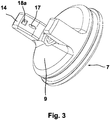
- the horn-air nozzle 17 coming first in the spray-jet direction 100 is elliptical in cross-section, while the horn-air nozzle 18a coming thereafter is square in cross-section.
- a rectangular shape is also possible.
- the Horn Kunststoffdüse 18 a is smaller here than the Horn Kunststoffdüse 17. In this embodiment, no control openings are present. But they could also be provided here. The same applies to the embodiments described below.
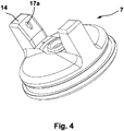
- FIG. 4 an air cap 7 is indicated for a nozzle head, in which only a single Hornluftdüse 17a per horn is provided.
- This Hornluftdüse 17a is tear-shaped ovaf formed, wherein in plan view of the inner wall 19 of the horn 14, the greater rounding of the oval in the upper region of the horn 14 is arranged.
- Fig. 5 illustrated unclaimed variant is also provided only a single Hornluftdüse 17b per horn.
- the shape of the Hornluftdüse 17 b is designed such that in plan view of the inner wall 19 of the horn 14 about the outline of the number 8 is visible.
- Fig. 6 is a similar, unclaimed variant as in Fig. 5 shown.
- the Hornluftdüse 17 b after Fig. 5 is here quasi split longitudinally to a two-part Horn Kunststoffdüse 17c.
- the two parts of the Horn Kunststoffdüse 17c are approximately crescent-shaped.
- the curves are directed outwards.
- a reverse arrangement is also possible. It is also possible to align the curves of the crescents up or down
- Fig. 7 shows an unclaimed variant in which an elliptical horn-shaped nozzle 17d in plan view widening in the longitudinal direction through the inner wall 19 of the horn 14 upwards or in the longitudinal direction.
- the flow surface 22 of the Hornluftdüse 17d is smooth.
- the flow surface 22 of the Horn Kunststoffdüse 17 d or another Horn Kunststoffdüse could also be wavy, knobbed, grooved, spiral or otherwise designed.
- the Hornluftdüse 17 a has not been made together with the air cap 7, but recessed as a continuous opening of a plastic body 23 which is inserted into a through hole in the inner wall 19 of the horn 14 accurately, in particular clipped.
- the insert is rectangular in shape - like the opening in the inner wall 19 of the horn 14.
- the insert and opening for the horn air nozzle 17a or another horn air nozzle may, of course, be designed differently; for the Function of the exemplary nozzle head these details do not play a major role.
- Such shaped openings for receiving nozzles can be easily manufactured not only in air caps made of plastic, but also in metal air caps such as steel (eg manganese steel).
- the insert 23 could also be glued into the opening in the side wall 19 of the horn 14.
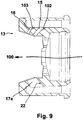
- Fig. 9 is in the upper half a variant of Fig. 1 shown; the same components are provided with the same reference numerals.
- the two Hornluftdüsen 15, 16 of the horn 13 at different angles to the spray jet direction 100.
- the angle 102 at the Hornluftdüse 15 is about 130 degrees
- the angle 103 in the Hornluftdüse 16 is about 120 degrees.
- Fig. 9 shows in the lower half of the sectional view a variant of a portion of the variant according to Fig. 4 , Here it can be clearly seen that the flow surface 22 of the Horn Kunststoffdüse 17 a in the vertical extent of the Horn Kunststoffdüse 17 a and in the spray jet 100 is formed smooth.
- Fig. 10 shows a variant of Fig. 8 and Fig. 4
- the flow surface 22 of the Hornluftdüse 17a in the vertical extent of this Hornluftdüse 17a may also be formed transversely corrugated and may have a plurality of flow-leading grooves 24 for the horn air.
- the grooves 24 may be configured as longitudinal grooves.
- control openings or control nozzle openings 12, 12 a are also provided here. The control nozzle openings 12, 12 a are aligned at an angle to the spray jet direction 100 out.
- control openings or control nozzle openings 12 a which are provided in the cover plate 9 of the air cap 7, not cylindrical as usual, but designed with a 100 in the spray jet direction flared diameter.
- the control nozzle openings 12a are designed approximately crescent-shaped, as Fig. 11 shows. The inner rounding of each crescent 12 points in this case to the air ring nozzle 5 or to the ink nozzle opening 3.
- One, two or more control nozzle openings per side can be made in any desired cross sections; the invention is not limited to the number of control nozzle openings.
- four control nozzle openings 12 and 12 a are provided, which are provided in pairs in areas of the cover plate 9 of the air nozzle 7, which are adjacent to the horns 12, 13.
- a cylindrical control nozzle opening 12 is adjacent to a non-cylindrical Control nozzle opening 12a.
- transverse grooves 24 or longitudinal grooves and lamellae, knobs or the like could be provided.
- control openings 12b are provided, which are formed even more irregular than in the example described above. They have namely in plan view or in the outline approximately the shape of a trifoliate cloverleaf.
- the two control openings 12b are provided next to the horns 13, 14 on the cover plate 9 of the air cap 7 next to the paint nozzle 3 and the air ring nozzle 5.
- Fig. 13 a variant of an air cap 7 is shown, in which the around the paint nozzle 3 extending around Lucasringdüse is not designed as usual cylindrical.
- the air ring nozzle 5a is here approximately hexagonal in plan view with two peaks 26, 27 formed.
- the tips 26, 27 are remote from the horns 13, 14. In another embodiment, the tips 26, 27 could also be facing the horns 13, 14.
- Fig. 14 shows another, in plan view strictly oval-shaped Beerringdüse 5b in combination with a similarly shaped paint nozzle 3a on an air cap 7 of a nozzle head.
- the round jet is preformed by the special shaping so that less horn air is required for the shaping of the broad jet than usual.
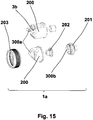
- the in Fig. 15 illustrated nozzle head 1a belongs to a high-pressure-fed special gun, which is ideal for processing large amounts of high-viscosity materials, because they are with supporting air atomization works.
- the nozzle head 1a has a so-called air nozzle 200 and a so-called pre-nozzle 201, which engages via a header 202 in the air nozzle 200.
- These components can be screwed onto the body of the spray gun, not shown, via a so-called air nozzle ring 203. All air or material-carrying openings or nozzles are usually designed cylindrical in such spray guns. From the central nozzle 3b, the material emerges in the form of a flat jet and is then shaped into an omnidirectional jet. It is proposed to design at least one of the openings 300a, 300b or air or material-carrying nozzles with non-cylindrical, in particular the Horn Kunststoffdüsen 300a. This also special effects can be achieved here.
- the invention is not limited to the previously described nozzle heads. It can also be used with advantage in other nozzle heads.
- non-cylindrical nozzles can of course be particularly easy to produce in nozzle heads or parts of nozzle heads, which are made of plastic, in particular injection-molded.
- nozzle heads made wholly or partly of metal usually stainless steel
- non-cylindrical nozzles can be realized by means of lost-wax casting or by means of inserts.
- the air nozzle / air ring nozzle can also be plugged, clipped, screwed or otherwise mounted or attached directly to the paint nozzle.
- the air nozzle and the paint nozzle can also be made in one piece.
- the entire nozzle device could be connected directly to a gun body with or without additional support means.
- the nozzle device is connected directly to the compressed air network or a material supply.
- the nozzle device can also represent a part of the air or material supply.
- the outer shape of the nozzle device may have any geometric shapes in the circumferential direction; In a particular embodiment, the entire spray device may additionally have any desired geometric shapes.
- the openings for beam shaping and the Horn Kunststoffdüsen or -auslassö réelleen need not necessarily be provided in projecting horns, but can be arranged for example in the plate 9, side elevations, tubes or in a circumferential ring around the plate.
- the number of openings in the horns as well as for beam shaping is basically arbitrary; several openings can also be arranged in segments in, for example, opposing areas (90 degrees, 45 degrees, 30 degrees ). It can be achieved by individual openings, several or many openings special beam shapes
- the energy of the compressed air can be optimally utilized, the jet formed better and the atomization can be improved.
- the droplet distribution in the jet can also be improved and a more uniform droplet distribution center can be produced.
- the reduction of the beam dependence can be achieved by other parameters, e.g. Inlet pressure, material viscosity and manufacturing tolerances and a volume reduction by reducing the exit velocity and reducing the compressed air requirement.
Landscapes
- Nozzles (AREA)
Description
- Die Erfindung betrifft einen Düsenkopf für eine Spritzvorrichtung nach dem Oberbegriff des Anspruchs 1.
- Solche Düsenköpfe sind an Spritzvorrichtungen zum hydrostatischen, pneumatischen oder kombinierten hydrostatischen und pneumatischen Zerstäuben von Farbe, Lack, Kleber oder anderen flüssigen Stoffen, insbesondere an Farbspritzpistolen gebräuchlich.
- Bei den Düsenköpfen solcher Spritzvorrichtungen hat die Luftringdüse die Funktion, die der Vorrichtung zugeführte Druckluft als einen Luftstrahl mit hoher Energie austreten zu lassen, der dabei Material aus einer anderen, zentralen Düse saugt, zerstäubt und einen materialbehafteten Spritzstrahl bildet. In seitlich angeordneten, nach vorne in Spritzstrahlrichtung weisenden Hörnern des Düsenkopfes sind Hornluftdüsen üblicherweise schräg und gleichsinnig zur Abströmrichtung auf den Spritzstrahl gerichtet, so dass die aus diesen Düsen austretenden Luftstrahlen den Spritzstrahl deformieren bzw. formen können. Durch die seitliche Deformation/Formung entsteht in Abhängigkeit von der Strömungsenergie (Luftmenge, Luftdruck, Strömungsgeschwindigkeit etc.) ein mehr oder weniger großer Flachstrahl oder ein Flach- und Rundstrahl.
- Zur Erzielung eines optimalen Arbeitsergebnisses muss der Spritzstrahl u.a. hinsichtlich Strahlbreite, Materialverteilung, Materialart und Tropfengröße angepasst werden. Die Anpassung erfolgt in Abhängigkeit von den physikalischen Randbedingungen (Eingangsluftdruck, Luftmenge usw.) im Wesentlichen durch konstruktive Anpassung der Mündung der zentralen Luftringdüse und der Hornluftdüsen. Für ausreichend homogene Spritzsträhle werden in der Regel ein, zwei, drei oder mehr Hornluftdüsen je Horn eingesetzt, welche in Wechselwirkung mit der zentralen Mündung der zentralen Düse stehen. Aus der Praxis sind Farbspritzpistolen mit ein, zwei oder mehr Hornluftdüsen bekannt, welche über die Kriterien gegenseitiger Abstand, Durchmesser, Winkel und Abstand zur Farbdüsenmündung, sowie deren Anzahl eine ausreichende Strahlformung und Zerstäubung sicher stellen. Die Hornluftdüsen sind dabei in einer Luftkappe vorgesehen, die auf dem Farbspritzpistolenkörper befestigt, meistens mittels Befestigungsringen aufgeschraubt ist. Die zentrale Luftdüse kann auch unmittelbar auf die Farbdüse oder aber auf den Farbspritzpistolenkörper aufgeschraubt, aufgeclipst oder anderweitig befestigt sein. Ein derartiger Düsenkopf ist beispielsweise aus dem Deutschen Gebrauchsmuster G 90 01 265.8 bekannt. Die Farbdüsenöffnungen und die Hornluftdüsenöffnungen sind wie allgemein üblich als Rundbohrungen ausgeführt.
- In der Praxis werden die Durchmesser der Hornfuftdüsen je nach Eingangsdruck und der individuell gewünschten Form des Spritzstrahls unterschiedlich groß ausgeführt. Die Wirkung der einzelnen Hornluftdüsen ist abhängig vom Eingangsdruck. Bei höheren Eingangsdrücken kann es dabei zum Spalten des Strahles kommen. Bei zu kleinen Eingangsdrücken kann es zu unerwünscht grober Zerstäubung mit kleiner Strahlbreite kommen. Auch besteht eine große Abhängigkeit des Materialdurchsatzes und weiteren Materialeigenschaften (z.B. Viskosität, Rheologie usw.), vom Eingangsdruck und der Anordnung der Hornluftdüsen. Zuweilen entstehen bei Verwendung einer oder mehrerer kleinerer Hornluftdüsen oder ungünstigen Bohrungswinkeln Probleme mit Rücknebel auf den Mündungsflächen der Düsen infolge der Sogwirkung bei kleineren Düsen- bzw. Bohrungsdurchmessern.
- Eine dazu abgewandelte Ausführung einer Lackierpistole mit einem Düsenkopf zeigt die Patentschrift
US 5,165,605 , wobei der Düsenkopf seitlich vorstehende Hörner mit schlitzförmigen Hornauslassöffnungen beschreibt. - In der Regel sind um die zentrale Düse zusätzlich kleine Steueröffnungen oder Hilfszerstäuberöffnungen angeordnet, die zur Strahlformung und Zerstäubung beitragen. Um den aus der zylindrischen Röhre der zentralen Luftdüsenöffnung vorgeformten Strahl in eine andere Form umzuwandeln, beispielsweise einen Rundstrahl in einen Flachstrahl umzuwandeln, sind hohe Energiemengen aus den Strahlformbohrungen und Hornbohrungen notwendig, welche zu hohen Energieverlusten führen und die Strahlformung einschränken.
- Ein großer Nachteil dieser Methode der Strahlformung ist, dass ein großer Teil der Energie der für die Strahlformung und Nachzerstäubung bereits durch die engen Bohrungen und Mehrfachaustritte an die Umgebungsluft (große Scherflächen an der Oberfläche im Zusammenhang mit großen Geschwindigkeitsunterschieden) verpufft.
- Oft müssen für geringfügig unterschiedliche Farb- oder Lackmaterialien modifizierte Düsenköpfe mit eventuell abweichenden Spritzparametern und Geometrien eingesetzt werden, um ein einwandfreies Spritzbild und damit das gewünschte Farb-, Lack- oder sonstiges Materialauftragsergebnis zu erhalten. Aufgabe der Erfindung ist es, einen Düsenkopf so zu verbessern, dass die Strömungsenergie der Druckluft optimal in Strahiformung, Strömungsgeschwindigkeit und damit in Zerstäubungsarbeit umgesetzt werden kann.
- Diese Aufgabe wird durch einen Düsenkopf mit den Merkmalen des Anspruchs 1 gelöst. Durch eine Formung des zentralen Strahles mit Hilfe wenigstens einer nichtzylindrischen Hornluftdüse, können zudem erhebliche Energiemengen zur Strahlformung eingespart werden.
- Die Erfindung geht von der Tatsache aus, dass bei zylindrischen Düsen die nötige Anpassung an die individuellen Erfordernisse lediglich durch Variationen der Durchmessermaße, der Länge und der Neigung der zylindrischen Bohrungen, deren gegenseitigem Abstand und dem Abstand zu den anderen Düsenöffnungen möglich ist. Nichtzylindrische Düsen können leichter strömungstechnisch optimiert und der individuellen Aufgabenstellung angepasst werden.
- Es versteht sich von selbst, dass dabei die Innengestalt, insbesondere die Mündung der Düsen, nichtzylindrisch sein sollen. Die Außengestalt der Düsen ist für die Strahlformung in der Regel unwesentlich.
- Vorteilhafte Ausgestaltungen der Erfindung sind in den übrigen Ansprüchen angegeben.
- In einer Weiterbildung der Erfindung wird eine variable Gestaltung der Steuerbohrungen vorgeschlagen, um eine effiziente Strahlformung zu erzielen.
- Gleiches gilt für die Formgebung der Strömungsbereiche der Luftdüse. Dadurch kann der Rundstrahl durch eine spezielle Formgebung so vorgeformt werden, dass weniger Hornluft für die Formung des Breitstrahls erforderlich ist und beliebige Strahlformen erzielt werden können.
- Insbesondere werden im Querschnitt elliptische oder wenigstens in etwa langlochförmige Düsen empfohlen.
- Durch eine sich in Richtung des Spritzstrahles erweiternde Düsenöffnung kann der Zerstäubungsvorgang weiter verbessert werden.
- Auch können Nuten, Lammellen, Luftleitschaufeln oder dergleichen zur Luftleitung in den Düsenöffnungen vorgesehen werden.
- Die nichtzylindrischen Düsen können in Metallteilen durch Zerspanen hergestellt werden. Besonders einfach können die nichtzylindrischen Düsen aus Kunststoff, insbesondere aus einem spritzgussfähigen Kunststoff hergestellt werden. Ebenso ist es möglich, solche Düsen in Kunststoff-Einlegeteile einzusetzen und in Düsenköpfen aus Metall zu befestigen.
- Auch können durch die Kombination von zylindrischen, konischen und anderen nichtzylindrischen Düsenöffnungen weitere vorteilhafte Effekte erzielt werden.
- Weitere vorteilhafte Einzelheiten sind in den nachfolgend erläuterten Figuren dargestellt.
- Dabei zeigt:
-
Fig. 1 einen Schnitt durch ein erstes Beispiel eines Düsenkopfes, -
Fig. 2 eine Draufsicht auf einen Teilbereich des Düsenkopfes nachFig. 1 , der eine nicht beanspruchte Variante zeigt, -
Fig. 3 eine nicht beanspruchte Variante vonFig. 2 , -
Fig. 4 bis 8 und11 bis 14 jeweils eine Draufsicht auf diverse Varianten eines Teilbereichs eines Düsenkopfes, -
Fig. 9 und10 jeweils eine Schnittansicht eines Düsenkopfes,
und -
Fig. 15 eine Explosionsdarstellung eines weiteren Düsenkopfes . - Der in
Fig. 1 und2 exemplarisch dargestellte Düsenkopf für eine Farbspritzpistole weist einen Farbdüsenkörper 1 mit einem im Wesentlichen zylindrischen Farbkanal 2 auf, der zentral in einer Farbdüse 3 mündet. In die Farbdüse 3 ist eine hohle Farbnadel 4 eingesetzt. Die Farbdüse 3 ist von einer Luftringdüse 5 umgeben, der Luft über Kanäle 6 zugeführt werden kann. Auf den Pistolenkörper ist eine Luftkappe 7 mittels eines Ringes 203, der üblicherweise als Luftdüsenring bezeichnet wird, aufgeschraubt. Die Luftkappe 7 könnte aber auch anderweitig am Pistolenkörper befestigt sein. Im vorliegenden Ausführungsbeispiel ist die Luftkappe 7 ist aus einem Kunststoff spritzgegossen. Sie weist einen ringförmigen Abschnitt 8 auf, welcher passend am Pistolenkörper anliegt. An den ringförmigen Abschnitt 8 schließt sich eine im Wesentlichen ebene Deckplatte 9 an. In einem sogenannten Mündungsbereich weist die Deckplatte 9 eine über diesen ebenen Bereich 9 überstehende ringförmige Erhebung 10 auf, in welcher mittig eine Öffnung 11 ausgespart ist. Die Öffnung 11 erstreckt sich, wenn die Farbdüse 3 montiert ist, um diese und damit um die Luftringdüse 5 herum. In der Deckplatte 9 sind seitlich der Öffnung 11 an mehreren Stellen durchgehende Steuerdüsen bzw. Steueröffnungen 12 vorgesehen. Die Steuerdüsenöffnungen 12 sind in einem Winkel von etwa 20 Grad zur Spritzstrahlrichtung 100 hin ausgerichtet. An zwei einander gegenüberliegenden Stellen besitzt die Luftkappe 7 jeweils ein Horn 13 bzw.14, welches sich nach vorne in Spritzstrahlrichtung 100 erstreckt. Im vorliegenden Ausführungsbeispiel sind die Hörner 13, 14 als im Querschnitt rechteckförmige, oben geschlossenen Körper ausgebildet. Jedes Horn 13,14 weist zwei in Spritzstrahlrichtung 100 hintereinander angeordnete Hornluftdüsen 15, 16 bzw. 17, 18 auf, die sich durch die Innenwand 19 der Hörner 13, 14 hindurch erstrecken. Die Hornluftdüsen 15,16,17,18 sind in schräg in Richtung des Spritzstrahls 100 ausgerichtet. Im vorliegenden Fall verlaufen die beiden Hornluftdüsen 15, 16 bzw. 17, 18 eines jeden Hornes 13 bzw. 14 im Wesentlichen parallel zueinander in einem Winkel 101 von etwa 140 Grad zur Spritzstrahlrichtung 100. Die Hornluftdüsen 15, 16 könnten aber auch in einem Winkel zueinander oder gegeneinander ausgerichtet sein. Sie können über jeweils einen in Längsrichtung durch das Horn 13 bzw. 14 verlaufenden Luftkanal 20 bzw. 21 mit Druckluft versorgt werden. Der mit hoher Energie aus der Luftringdüse 5 austretende Ringluftstrahl saugt die Farbe aus der Farbdüse 3, wobei sich ein Rundstrahl bildet, der in Spritzstrahlrichtung 100 abströmt. Die aus den Hornluftdüsen 15, 16 bzw. 17, 18 austretenden Hornluftstrahlen sind auf den Rundstrahl gerichtet und strömen schräg und gleichsinnig zur Spritzstrahlrichtung 100 und deformieren den Rundstrahl zum gewünschten Breitstrahl. - Die Hornluftdüsen 15, 16 bzw. 17, 18 sind strömungstechnisch so optimiert, dass der Rundstrahl eine homogene Strahlformung erfährt und die gewünschte Strahlbreite erzielt wird, ohne den Spritzstrahl zu spalten. Wie
Fig. 2 einer nicht beanspruchten Ausgestaltung zeigt, sind beide Hornluftdüsen 17, 18 des Hornes 14 im Querschnitt elliptisch und gleich groß ausgebildet. Im vorliegenden Ausführungsbeispiel liegen die schmalen Rundungen der Ellipsen oben bzw. unten. Die Ellipsen könnten aber auch quer zur Längserstreckung des Hornes 14 bzw. 13 angeordnet sein. Kombinationen solcher Ellipsen sind ebenfalls möglich. Diese spezielle Gestaltung der Hornluftdüsen 17, 18 konnte problemlos durch Spritzgießen der Luftkappe 7 realisiert werden. Dabei ist es nicht zwingend nötig, eine separate Luftkappe 7 vorzusehen; der Düsenkopf 1 könnte auch anders (einstückig) gestaltet sein. Wesentlich im Sinne der Erfindung sind die nichtzylindrischen Düsen im Düsenkopf. - Im vorliegenden Beispiel ist die Farbnadel 4 hohl und weist eine entlang ihrer Längsachse zylindrische Öffnung 4a auf, durch welche ein Vakuum oder ein Überdruck im Spritzstrahl erzeugt werden kann. In einer besonderen Variante wird über die Hohlnadel 4 eine weitere Lackkomponente in den Spritzstrahl injiziert. Zu diesem Zweck wird die Einlassöffnung der Nadel 4 an entsprechende, Material beinhaltende Vorrichtungen angeschlossen. In einer speziellen Ausgestaltung kann die Öffnung 4a nichtzylindrisch, z.B. im Querschnitt oval oder in jeder anderen beliebigen nichtzylindrischen Form ausgeführt sein.
- Die Öffnung 4a kann an Druckluft oder Vakuum angeschlossen sein.
- Andererseits könnte die Farbnadel 4 auch nicht hohl, sondern aus Vollkörper ausgebildet sein. Die Nadel 4 wird dabei vorteilhafterweise immer so gestaltet sein, dass ihre äußere Form an der Dichtungsstelle bzw. Anlagefläche an der Farbdüse 3 der inneren Form dieser Düse entspricht, sodass dichtende Paarungen erzielt werden.
- Bei der nicht beanspruchten Variante nach
Fig. 3 ist die in Spritzstrahlrichtung 100 zuerst kommende Hornluftdüse 17 im Querschnitt elliptisch ausgebildet, während die danach kommende Hornluftdüse 18a im Querschnitt quadratisch ausgebildet ist. Eine Rechteckform ist ebenfalls möglich. Die Hornluftdüse 18a ist hier kleiner als die Hornluftdüse 17. Bei diesem Ausführungsbeispiel sind keine Steueröffnungen vorhanden. Sie könnten aber auch hier vorgesehen werden. Gleiches gilt auch für die nachfolgend beschriebenen Ausführungsformen. - Im nicht beanspruchten Beispiel nach
Fig. 4 ist eine Luftkappe 7 für einen Düsenkopf angedeutet, bei der lediglich eine einzige Hornluftdüse 17a pro Horn vorgesehen ist. Diese Hornluftdüse 17a ist tropfenförmig-ovaf geformt, wobei in Draufsicht auf die Innenwand 19 des Horns 14 die größere Rundung des Ovals im oberen Bereich des Horns 14 angeordnet ist. - Bei der in
Fig. 5 dargestellten nicht beanspruchten Variante ist ebenfalls lediglich eine einzige Hornluftdüse 17b pro Horn vorgesehen. Hier ist Form der Hornluftdüse 17b derart gestaltet, dass in Draufsicht auf die Innenwand 19 des Horns 14 etwa der Umriss der Zahl 8 sichtbar ist. - In
Fig. 6 ist eine ähnliche, nicht beanspruchte Variante wie inFig. 5 dargestellt. In der Luftkappe 7 ist die Hornluftdüse 17 b nachFig. 5 ist hier quasi längs aufgeteilt zu einer zweiteiligen Hornluftdüse 17c. Die beiden Teile der Hornluftdüse 17c sind etwa halbmondförmig. In der dargestellten Ausführungsform sind die Rundungen dabei nach außen gerichtet. Eine umgekehrte Anordnung ist ebenfalls möglich. Ebenso ist es möglich, die Rundungen der Halbmonde nach oben bzw. unten auszurichten - Bei der nicht beanspruchten Variante nach
Fig. 6a sind drei im Querschnitt rechteckige Hornluftdüsen 18b1, 18b2, 18b3 im Horn 14 der Luftkappe 7 vorgesehen. - Die bislang beschriebenen Hornluftdüsen haben in Längsrichtung überall das gleiche Innenmaß. Es sind aber auch Hornluftdüsen einsetzbar, die sich in Längsrichtung erweitern oder verjüngen.
-
Fig. 7 zeigt eine nicht beanspruchte Variante, bei der sich eine in Draufsicht elliptische Hornluftdüse 17d in Längserstreckung durch die Innenwand 19 des Horns 14 nach oben hin bzw. in Längsrichtung erweitert. Die Strömungsfläche 22 der Hornluftdüse 17d ist dabei glatt ausgebildet. - Die Strömungsfläche 22 der Hornluftdüse 17d oder einer anderen Hornluftdüse könnte auch gewellt, genoppt, geriffelt, spiralförmig oder andersartig gestaltet sein.
- Bei der nicht beanspruchten Variante nach
Fig. 8 ist an der Luftkappe 7 die gleiche Hornluftdüse 17a wie inFig. 4 vorgesehen. Hier ist die Hornluftdüse 17a aber nicht gemeinsam mit der Luftkappe 7 gefertigt worden, sondern als durchgehende Öffnung aus einem Kunststoffkörper 23 ausgespart, der in eine durchgehende Öffnung in der Innenwand 19 des Horns 14 passgenau eingesetzt, insbesondere eingeclipst ist. Im vorliegenden Beispiel ist der Einsatz im Umriss rechteckförmig gestaltet - wie die Öffnung in der Innenwand 19 des Horns 14. Der Einsatz und die Öffnung für die Hornluftdüse 17a oder eine andere Hornluftdüse können selbstverständlich auch anders gestaltet sein; für die Funktion des exemplarischen Düsenkopfes spielen diese Einzelheiten keine große Rolle. Derart geformte Öffnungen zur Aufnahme von Düsen können nicht nur bei Luftkappen aus Kunststoff, sondern grundsätzlich auch bei Luftkappen aus Metall wie beispielsweise Stahl (z.B. Manganstahl) problemlos hergestellt werden. - Der Einsatz 23 könnte auch in die Öffnung in der Seitenwand 19 des Horns 14 geklebt sein.
- Im Beispiel nach
Fig. 9 ist in der oberen Hälfte eine Variante vonFig. 1 dargestellt; gleiche Bauteile sind mit gleichen Bezugszeichen versehen. In Abweichung vonFig. 1 verlaufen hier die beiden Hornluftdüsen 15, 16 des Horns 13 in unterschiedlichen Winkeln zur Spritzstrahlrichtung 100. Der Winkel 102 bei der Hornluftdüse 15 beträgt etwa 130 Grad, während der Winkel 103 bei der Hornluftdüse 16 etwa 120 Grad beträgt. -
Fig. 9 zeigt in der unteren Hälfte der Schnittansicht eine Variante eines Teilbereichs der Variante nachFig. 4 . Hier ist deutlich ersichtlich, dass die Strömungsfläche 22 der Hornluftdüse 17a in Höhenerstreckung der Hornluftdüse 17a bzw. in Spritzstrahlrichtung 100 glatt ausgebildet ist. - Das nicht beanspruchte Beispiel nach
Fig. 10 zeigt eine Variante vonFig. 8 undFig. 4 . Hier ist deutlich ersichtlich, dass die Strömungsfläche 22 der Hornluftdüse 17a in Höhenerstreckung dieser Hornluftdüse 17a auch quer geriffelt ausgebildet sein kann und eine Vielzahl strömungsführende Nuten 24 für die Hornluft aufweisen kann. In einer anderen Gestaltung können die Nuten 24 als Längsnuten ausgestaltet sein. Weiterhin sind auch hier Steueröffnungen bzw. Steuerdüsenöffnungen 12, 12 a vorgesehen. Die Steuerdüsenöffnungen 12, 12 a sind in einem Winkel zur Spritzstrahlrichtung 100 hin ausgerichtet. Einige Steueröffnungen bzw. Steuerdüsenöffnungen 12 a, die in der Deckplatte 9 der Luftkappe 7 vorgesehen sind, nicht wie üblich zylindrisch, sondern mit einem sich in Spritzstrahlrichtung 100 konisch erweiternden Durchmesser gestaltet. In Draufsicht sind die Steuerdüsenöffnungen 12a etwa halbmondförmig gestaltet, wieFig. 11 zeigt. Die Innenrundung jedes Halbmonds 12 weist dabei zur Luftringdüse 5 bzw. zur Farbdüsenöffnung 3. Es können ein, zwei oder mehr Steuerdüsenöffnungen pro Seite in beliebigen Querschnitten ausgeführt werden; die Erfindung ist nicht auf die Anzahl der Steuerdüsenöffnungen beschränkt. Im vorliegenden Beispiel sind vier Steuerdüsenöffnungen 12 und 12a vorgesehen, die paarweise in Bereichen der Deckplatte 9 der Luftdüse 7 vorgesehen sind, die neben den Hörnern 12, 13 liegen. Jeweils eine zylindrische Steuerdüsenöffnung 12 liegt dabei neben einer nichtzylindrischen Steuerdüsenöffnung 12a. Es können aber auch nur nichtzylindrische oder aber nur zylindrische Steuerdüsenöffnungen vorgesehen werden. - Anstatt der Quernuten 24 oder Längsnuten könnten auch Lamellen, Noppen oder dergleichen vorgesehen werden.
- Bei der nicht beanspruchten Variante nach
Fig. 12 sind anstatt vier Steueröffnungen lediglich zwei Steueröffnungen 12b vorgesehen, die noch unregelmäßiger als bei dem zuvor beschriebenen Beispiel ausgebildet sind. Sie besitzen nämlich in Draufsicht bzw. im Umriss etwa die Form eines dreiblättrigen Kleeblatts. Die beiden Steueröffnungen 12b sind neben den Hörnern 13, 14 auf der Deckplatte 9 der Luftkappe 7 neben der Farbdüse 3 und der Luftringdüse 5 vorgesehen. - Mit den zuvor beschriebenen Querschnittsformen der Hornluftdüsen werden spezielle, strömungstechnisch optimierte Kanäle für die Hornluft geschaffen. Selbstverständlich sind auch andere Querschnittsformen und Kombinationen davon möglich.
- In
Fig. 13 ist eine Variante einer Luftkappe 7 gezeigt, bei welcher die sich um die Farbdüse 3 herum erstreckende Luftringdüse nicht wie üblich zylindrisch gestaltet ist. Die Luftringdüse 5a ist hier in Draufsicht etwa sechseckig mit zwei Spitzen 26, 27 geformt. Die Spitzen 26, 27 sind dabei von den Hörnern 13, 14 abgewandt. in anderer Ausgestaltung könnten die Spitzen 26, 27 auch den Hörnern 13, 14 zugewandt sein. -
Fig. 14 zeigt eine andere, in Draufsicht streng oval geformte Luftringdüse 5b in Kombination mit einer ebenso geformten Farbdüse 3a an einer Luftkappe 7 eines Düsenkopfes 1. - Bei den beiden zuletzt beschriebenen Varianten wird der Rundstrahl durch die spezielle Formgebung so vorgeformt, dass weniger Hornluft für die Formung des Breitstrahls als üblich erforderlich ist.
- Andere Ausgestaltungen des Düsenkopfes mit einer anderen Luftkappe oder auch ohne Luftkappe sind möglich; wesentlich im Sinne der Erfindung sind die nichtzylindrischen Öffnungen im Düsenkopf.
- Der in
Fig. 15 dargestellte Düsenkopf 1a gehört zu einer hochdruckgespeisten Spezial-Pistole, die ideal für das Verarbeiten großer Mengen hochviskoser Materialien ist, weil sie mit unterstützender Luftzerstäubung arbeitet. Der Düsenkopf 1a besitzt eine sogenannte Luftdüse 200 und eine sogenannte Vordüse 201, die über einen Vorsatz 202 in die Luftdüse 200 eingreift. Diese Bauteile sind über einen sogenannten Luftdüsenring 203 auf den Körper der nicht dargestellten Spritzpistole aufschraubbar. Sämtliche luft- oder materialführenden Öffnungen bzw. Düsen sind bei solchen Spritzpistolen üblicherweise zylindrisch gestaltet. Aus der zentralen Düse 3b tritt das Material in Form eines Flachstrahls aus und wird danach zu einem Rundstrahl geformt. Es wird vorgeschlagen, wenigstens eine der Öffnungen 300a, 300b bzw. luft- oder materialführenden Düsen mit nichtzylindrisch zu gestalten, insbesondere die Hornluftdüsen 300a. Dadurch können auch hier Spezialeffekte erzielt werden. - Beliebige Kombinationen der beschriebenen Düsenvarianten sind selbstverständlich möglich und können zu besonders vorteilhaften Spritzergebnissen führen.
- Sämtliche Kombinationen von zylindrischen und nichtzylindrischen Düsen gemäß des Hauptanspruchs sind je nach gewünschtem Arbeitsergebnis denkbar und fallen unter die vorliegende Erfindung.
- Die Erfindung ist selbstverständlich nicht auf die zuvor beschriebenen Düsenköpfe beschränkt. Sie kann auch mit Vorteil bei anderen Düsenköpfen eingesetzt werden.
- Die vorgeschlagenen nichtzylindrischen Düsen lassen sich selbstverständlich besonders einfach in Düsenköpfen bzw. Teilen von Düsenköpfen herstellen, die aus Kunststoff gefertigt, insbesondere spritzgegossen werden. Bei Düsenköpfen, die ganz oder teilweise aus Metall (üblicherweise Edelstahl) gefertigt werden, können nichtzylindrische Düsen mittels Wachsausschmelzguss oder über Einsätze realisiert werden.
- In weiteren Ausführungsformen kann die Luftdüse/Luftringdüse auch direkt auf die Farbdüse aufgesteckt, aufgeclipst, aufgeschraubt oder anderweitig montiert bzw. befestigt werden. Die Luftdüse und die Farbdüse können auch einstückig ausgeführt sein.
- Die gesamte Düseneinrichtung könnte mit oder ohne zusätzliche Trägereinrichtung direkt mit einem Pistolenkörper verbunden werden.
- In einer weiteren Ausgestaltungsform wird die Düseneinrichtung direkt mit dem Druckluftnetz bzw. einer Materialversorgung verbunden.
- Die Düseneinrichtung kann in einer weiteren Ausführungsform auch einen Teil der Luft- oder Materialversorgung darstellen.
- Auch kann die äußere Form der Düseneinrichtung beliebige geometrische Formen in Umfangsrichtung aufweisen; in einer besonderen Ausführungsform kann die gesamte Spritzvorrichtung zusätzlich beliebige geometrische Formen aufweisen.
- Die Öffnungen zur Strahlformung sowie die Hornluftdüsen bzw. -auslassöffnungen müssen nicht zwangsweise in vorspringenden Hörnern vorgesehen sein, sondern können beispielsweise in der Platte 9, seitlichen Erhöhungen, Rohren oder in einem um die Platte umlaufenden Ring angeordnet Werden.
- Die Anzahl der Öffnungen in den Hörnern wie auch zur Strahlformung ist grundsätzlich beliebig; mehrere Öffnungen können auch in Segmenten zusammengefasst in beispielsweise einander gegenüberliegenden Bereichen (90 Grad, 45 Grad, 30 Grad.....) angeordnet werden. Dabei können durch einzelne Öffnungen, mehrere oder viele Öffnungen besondere Strahlformen erzielt werden
- Durch die beschriebenen und weitere denkbaren strömungstechnisch optimierten Düsenöffnungen kann die Energie der Druckluft optimaler ausgenutzt werden, der Strahl besser ausgeformt und die Zerstäubung verbessert werden. Dadurch können neben feineren Tröpfchen auch die Tröpfchenverteilung im Strahl verbessert und ein gleichmäßigeres Tropfchenverteilungszentrum erzeugt werden. Ebenso erreicht werden kann die Reduzierung der Strahlabhängigkeit von anderen Parametern wie z.B. Eingangsdruck, Materialviskosität und Fertigungstoleranzen sowie eine Lautstärkereduzierung durch Reduzierung der Austrittsgeschwindigkeit und Verringerung des Druckluftbedarfes.
Claims (14)
- Düsenkopf für eine Spritzvorrichtung, mit einer zentralen Materialdüse, einer diese Materialdüse umgebende Luftringdüse und mit mindestens zwei seitlich vorstehenden Hörnern, in welche jeweils mindestens eine Hornluftdüse eingearbeitet ist, wobei wenigstens eine Hornluftdüse (15, 16, 17, 17a, 17b, 17c, 18, 18a,18b1, 18b2, 18b3, 300a) eine nichtzylindrische Gestalt aufweist, dadurch gekennzeichnet, dass die Luftringdüse (5a, 5b) eine nichtzylindrische Gestalt aufweist,
- Düsenkopf nach Anspruch 1, dadurch gekennzeichnet, dass eine Luftringdüse mit nichtzylindrischer Gestalt mit wenigstens mit einer Hornluftdüse kombiniert ist, die eine zylindrische Gestalt aufweist.
- Düsenkopf nach einem der vorhergehenden Ansprüche, dadurch gekennzeichnet, dass neben der Luftringdüse (5) wenigstens eine Steueröffnung (12a, 12b) vorgesehen ist, welche eine nichtzylindrische Gestalt aufweist.
- Düsenkopf nach einem der vorhergehenden Ansprüche, dadurch gekennzeichnet, dass wenigstens eine Düse (17a) über einen Einsatz (23) mit dem Düsenkopf (1) bzw. mit einem damit verbundenen Bauteil (7), insbesondere der Luftkappe einer Farbspritzpistole verbunden ist.
- Düsenkopf nach einem der vorhergehenden Ansprüche, dadurch gekennzeichnet, dass wenigstens eine der Düsen (12a, 12b, 17, 17a, 17b, 17c, 18a, 18b1, 18b2, 18b3) im Querschnitt elliptisch, tropfenförmig-oval oder etwa halbmondförmig ausgebildet ist, etwa die Form eines dreiblättrigen Kleeblatts oder eines Rechtecks, insbesondere eines Quadrats aufweist oder im Querschnitt bzw. im Umriss etwa der Zahl 8 gleicht.
- Düsenkopf nach einem der vorhergehenden Ansprüche, dadurch gekennzeichnet, dass die Strömungsfläche (22) wenigstens einer der Düsen (17d) gewellt, genoppt, geriffelt, spiralförmig oder andersartig gestaltet ist.
- Düsenkopf nach Anspruch 6, dadurch gekennzeichnet, dass wenigstens eine der Düsen (17a) wenigstens eine strömungsführende Nut (24), insbesondere eine Längsnut aufweist.
- Düsenkopf nach einem der vorhergehenden Ansprüche, dadurch gekennzeichnet, dass wenigstens ein Horn (13, 14) nur eine einzige Hornluftdüse (17a, 17b), zwei Hornluftdüsen (15, 16, 17,17c, 18,18a) oder drei Hornluftdüsen (18b1, 18b2, 18b3) aufweist.
- Düsenkopf nach einem der vorhergehenden Ansprüche, dadurch gekennzeichnet, dass sich das Innenmaß der Düsen (12a) in Längsrichtung erweitert oder verjüngt.
- Düsenkopf nach einem der vorhergehenden Ansprüche, dadurch gekennzeichnet, dass eine materialführende Nadel vorgesehen ist, die als Vollkörper oder als hohle Nadel (4) mit einer materialführenden Öffnung (4a) ausgebildet ist.
- Düsenkopf nach Anspruch 10, dadurch gekennzeichnet, dass die Öffnung (4a) in der hohlen Nadel (4) eine nichtzylindrische Gestalt aufweist.
- Düsenkopf nach einem der vorhergehenden Ansprüche, dadurch gekennzeichnet, dass der Düsenkopf (1) wenigstens bereichsweise aus Kunststoff gefertigt, insbesondere aus Kunststoff gespritzt ist.
- Düsenkopf nach Anspruch 12, dadurch gekennzeichnet, dass ein düsenführender Einsatz (23) im Düsenkopf (1) aus Kunststoff und der Düsenkopf ansonsten aus Metall, insbesondere aus Stahl gefertigt ist.
- Düsenkopf nach einem der vorhergehenden Ansprüche, dadurch gekennzeichnet, dass er direkt oder über eine Trägereinrichtung mit einem Körper einer pneumatischen oder hydrostatischen oder kombinierten pneumatischen/hydrostatischen Spritzpistole verbunden werden kann.
Applications Claiming Priority (2)
| Application Number | Priority Date | Filing Date | Title |
|---|---|---|---|
| DE202010007355U DE202010007355U1 (de) | 2010-05-28 | 2010-05-28 | Düsenkopf für eine Spritzvorrichtung |
| PCT/EP2011/002544 WO2011147555A1 (de) | 2010-05-28 | 2011-05-21 | Düsenkopf für eine spritzvorrichtung |
Publications (2)
| Publication Number | Publication Date |
|---|---|
| EP2576079A1 EP2576079A1 (de) | 2013-04-10 |
| EP2576079B1 true EP2576079B1 (de) | 2019-09-11 |
Family
ID=44511669
Family Applications (1)
| Application Number | Title | Priority Date | Filing Date |
|---|---|---|---|
| EP11723182.9A Active EP2576079B1 (de) | 2010-05-28 | 2011-05-21 | Düsenkopf für eine spritzvorrichtung |
Country Status (8)
| Country | Link |
|---|---|
| US (1) | US9782784B2 (de) |
| EP (1) | EP2576079B1 (de) |
| JP (2) | JP5875580B2 (de) |
| CN (2) | CN106925462A (de) |
| AU (1) | AU2011257605B2 (de) |
| CA (1) | CA2797990C (de) |
| DE (1) | DE202010007355U1 (de) |
| WO (1) | WO2011147555A1 (de) |
Families Citing this family (39)
| Publication number | Priority date | Publication date | Assignee | Title |
|---|---|---|---|---|
| DE502007000825D1 (de) | 2006-12-05 | 2009-07-16 | Sata Gmbh & Co Kg | Belüftung für den Fließbecher einer Farbspritzpistole |
| AU2008352594B2 (en) | 2008-03-12 | 2013-11-21 | Jeffrey D. Fox | Disposable spray gun cartridge |
| DE202008014389U1 (de) * | 2008-10-29 | 2010-04-08 | Sata Gmbh & Co. Kg | Fließbecher für eine Farbspritzpistole |
| DE102009032399A1 (de) | 2009-07-08 | 2011-01-13 | Sata Gmbh & Co. Kg | Farbspritzpistole |
| DE202010007355U1 (de) * | 2010-05-28 | 2011-10-20 | Sata Gmbh & Co. Kg | Düsenkopf für eine Spritzvorrichtung |
| US9333519B2 (en) | 2010-12-02 | 2016-05-10 | Sata Gmbh & Co. Kg | Spray gun and accessories |
| GB2491929B (en) | 2011-06-17 | 2017-07-26 | Earlex Ltd | Spray gun |
| CN103517765B (zh) | 2011-06-30 | 2017-09-12 | 萨塔有限两合公司 | 易清洗的喷枪、用于喷枪的附件及安装和拆卸方法 |
| JP2013244429A (ja) * | 2012-05-24 | 2013-12-09 | Nissan Motor Co Ltd | 塗装ハンドガン用エアキャップ |
| EP3021982B1 (de) * | 2013-07-15 | 2020-02-26 | 3M Innovative Properties Company | Luftkappen mit vorderen geometrieeinsätzen für flüssigkeitsspritzpistolen |
| CA155474S (en) | 2013-09-27 | 2015-08-27 | Sata Gmbh & Co Kg | Spray gun |
| DE202013105779U1 (de) | 2013-12-18 | 2015-03-19 | Sata Gmbh & Co. Kg | Luftdüsenabschluss für eine Lackierpistole |
| CN105289870B (zh) | 2014-07-31 | 2019-09-24 | 萨塔有限两合公司 | 喷枪的制造方法、喷枪、喷枪本体以及盖 |
| USD758537S1 (en) | 2014-07-31 | 2016-06-07 | Sata Gmbh & Co. Kg | Paint spray gun rear portion |
| CA159961S (en) | 2014-07-31 | 2015-07-17 | Sata Gmbh & Co Kg | Spray gun |
| USD768820S1 (en) | 2014-09-03 | 2016-10-11 | Sata Gmbh & Co. Kg | Paint spray gun with pattern |
| JP6444163B2 (ja) * | 2014-12-22 | 2018-12-26 | アネスト岩田株式会社 | スプレーガン |
| CN107427851B (zh) * | 2015-03-05 | 2020-06-30 | 涂层国外知识产权有限公司 | 具有用以确保重力给送的中空针的喷枪和使用该喷枪的方法 |
| EP3265237B1 (de) * | 2015-03-05 | 2020-11-04 | Coatings Foreign IP Co. LLC | Sprühpistole mit hoher übertragungseffizienz und verfahren zur deren verwendung |
| US10821454B2 (en) | 2015-03-11 | 2020-11-03 | Axalta Coating Systems Ip Co., Llc | Spray gun with a hollow needle and single stage or two stage nozzle and method for use thereof |
| DE102015006484A1 (de) | 2015-05-22 | 2016-11-24 | Sata Gmbh & Co. Kg | Düsenanordnung für eine Spritzpistole, insbesondere Farbspritzpistole und Spritzpistole, insbesondere Farbspritzpistole |
| DE102015016474A1 (de) | 2015-12-21 | 2017-06-22 | Sata Gmbh & Co. Kg | Luftkappe und Düsenanordnung für eine Spritzpistole und Spritzpistole |
| CN205966208U (zh) | 2016-08-19 | 2017-02-22 | 萨塔有限两合公司 | 风帽组件以及喷枪 |
| CN205995666U (zh) | 2016-08-19 | 2017-03-08 | 萨塔有限两合公司 | 喷枪及其扳机 |
| JP6496330B2 (ja) * | 2017-01-18 | 2019-04-03 | 本田技研工業株式会社 | 吐出装置 |
| DE102017103335A1 (de) * | 2017-02-17 | 2018-08-23 | J. Wagner Gmbh | Sprühkopf für ein Farbspritzgerät und Farbspritzgerät |
| CN108906353B (zh) * | 2018-07-27 | 2019-10-29 | 江苏省中跃涂装设备有限公司 | 一种用于喷涂机器人的均匀喷涂出料口 |
| CN112533705B (zh) | 2018-08-01 | 2023-07-04 | 萨塔有限两合公司 | 喷枪的喷嘴组、喷枪系统、制造喷嘴模块的方法、为上漆任务从喷嘴组选出喷嘴模块的方法、选择系统和计算机程序产品 |
| DE102018118737A1 (de) | 2018-08-01 | 2020-02-06 | Sata Gmbh & Co. Kg | Düse für eine Spritzpistole, Düsensatz für eine Spritzpistole, Spritzpistolen und Verfahren zur Herstellung einer Düse für eine Spritzpistole |
| DE102018118738A1 (de) | 2018-08-01 | 2020-02-06 | Sata Gmbh & Co. Kg | Grundkörper für eine Spritzpistole, Spritzpistolen, Spritzpistolen-Set, Verfahren zur Herstellung eines Grundkörpers für eine Spritzpistole und Verfahren zum Umrüsten einer Spritzpistole |
| DE102018122004A1 (de) | 2018-09-10 | 2020-03-12 | Sata Gmbh & Co. Kg | Lackierpistole, Materialauftragssystem und Verfahren zu dessen Betrieb |
| GB201819581D0 (en) | 2018-11-30 | 2019-01-16 | Labman Automation Ltd | Spray head |
| EP3932533A4 (de) * | 2019-03-01 | 2022-11-23 | Kawata Mfg. Co., Ltd. | Pulverbeschichtungsvorrichtung und beschichtungsverfahren, pulverdispersionsvorrichtung und pulverdispersionsverfahren |
| DE102020106172A1 (de) | 2020-03-06 | 2021-09-09 | Sata Gmbh & Co. Kg | Spritzpistole, insbesondere druckluftzerstäubende Farbspritzpistole, insbesondere handgeführte druckluftzerstäubende Farbspritzpistole |
| GB202004933D0 (en) * | 2020-04-03 | 2020-05-20 | Renishaw Plc | Measuring device and method |
| DE102020123769A1 (de) | 2020-09-11 | 2022-03-17 | Sata Gmbh & Co. Kg | Dichtelement zum Abdichten eines Übergangs zwischen einem Grundkörper einer Spritzpistole und einem Anbauteil einer Spritzpistole, Anbauteil, insbesondere Farbdüsenanordnung, für eine Spritzpistole und Spritzpistole, insbesondere Farbspritzpistole |
| WO2022130303A1 (en) | 2020-12-18 | 2022-06-23 | 3M Innovative Properties Company | Two-fluid nozzle with an arcuate opening |
| US12208407B2 (en) | 2021-03-05 | 2025-01-28 | Graco Minnesota Inc. | Alignment tool for a spray gun air cap |
| KR102653970B1 (ko) * | 2022-10-26 | 2024-04-03 | 스프레이시스템코리아 유한회사 | 고점도 스프레이 장치 |
Family Cites Families (489)
| Publication number | Priority date | Publication date | Assignee | Title |
|---|---|---|---|---|
| DE1321940U (de) | ||||
| US459433A (en) | 1891-09-15 | Herbert g | ||
| US40433A (en) | 1863-10-27 | Improved lubricator | ||
| US581107A (en) | 1897-04-20 | emery | ||
| DE460381C (de) | 1928-05-25 | Ernst Koerber | Rohrverbindung | |
| US563505A (en) | 1896-07-07 | Can-cleaner | ||
| US552715A (en) | 1896-01-07 | lugrin | ||
| CA521511A (en) | 1956-02-07 | P. Dalrymple William | Spray guns | |
| US327260A (en) | 1885-09-29 | Series of labels for tacks | ||
| US552213A (en) | 1895-12-31 | Speed-indicating alarm | ||
| US548816A (en) | 1895-10-29 | Apparatus for manufacturing gas | ||
| US574880A (en) | 1897-01-12 | John s | ||
| US459432A (en) | 1891-09-15 | Oven for baking japanned ware | ||
| US644803A (en) | 1899-10-06 | 1900-03-06 | Henry D Justi | Artificial tooth-crown. |
| US672012A (en) | 1900-01-17 | 1901-04-16 | Wilhelm Adolph August Roeper | Registering apparatus for use in connection with lifting or hoisting devices. |
| DE212979C (de) | 1909-01-08 | 1909-09-06 | ||
| US1711221A (en) | 1921-04-04 | 1929-04-30 | George R Blakeslee | Washing machine |
| US1703383A (en) | 1922-12-29 | 1929-02-26 | Matthews W N Corp | Spray gun |
| US1703384A (en) | 1924-10-18 | 1929-02-26 | Matthews W N Corp | Paint gun |
| GB259721A (de) * | 1924-11-10 | |||
| US1662496A (en) | 1926-08-16 | 1928-03-13 | Edward F Forsgard | Dishwashing machine |
| DE510362C (de) | 1929-11-15 | 1930-10-18 | Karl Ludwig Dipl Ing | Verfahren zur Herstellung von Spritzpistolen |
| US1889201A (en) | 1931-05-09 | 1932-11-29 | Joseph E Holveck | Spray nozzle |
| US2008381A (en) | 1933-12-05 | 1935-07-16 | George R Beeg | Dispensing device |
| FR789762A (fr) | 1934-08-06 | 1935-11-06 | Laiterie Des Fermiers Reunis | Raccord rapide pour tuyauteries destinées aux liquides alimentaires |
| US2049700A (en) | 1935-07-15 | 1936-08-04 | Binks Mfg Co | Air nozzle for flat-spraying appliances |
| US2051210A (en) | 1935-09-13 | 1936-08-18 | Binks Mfg Co | Air nozzle for spray appliances |
| US2070696A (en) | 1935-12-11 | 1937-02-16 | Vilbiss Co | Spray head |
| US2204599A (en) | 1936-01-09 | 1940-06-18 | Jenkins Alexander Frederick | Spray gun |
| US2125445A (en) * | 1937-02-05 | 1938-08-02 | Worthington Pump & Mach Corp | Spray nozzle |
| US2116036A (en) | 1937-04-14 | 1938-05-03 | Charles R Terry | Lock nut |
| CH203668A (de) | 1937-05-27 | 1939-03-31 | Allgaeuer Alpenmilch Aktienges | Gefäss zur Vakuumkonservierung, insbesondere von Lebens- und Genussmitteln. |
| US2198441A (en) | 1937-08-28 | 1940-04-23 | Lewis Co G B | Golf ball washer |
| US2269057A (en) | 1938-01-10 | 1942-01-06 | Alexander F Jenkins | Spraying device |
| US2356865A (en) | 1942-06-06 | 1944-08-29 | Amen David Abbott | Spray gun |
| US2416923A (en) * | 1943-08-30 | 1947-03-04 | Alexander Milburn Company | Spray gun |
| US2557593A (en) | 1944-04-26 | 1951-06-19 | Atlas Diesel Ab | Operating mechanism for spray guns |
| US2416856A (en) | 1945-03-26 | 1947-03-04 | Thomsen Hugo | Binder |
| US2559091A (en) | 1945-12-01 | 1951-07-03 | Mizzy Inc | Method and solution for producing insecticidal aerosols |
| US2612899A (en) | 1946-11-09 | 1952-10-07 | Inland Mfg Co | Radiator back flush and cleaning booth |
| US2557606A (en) | 1948-02-12 | 1951-06-19 | Atlas Diesel Ab | Adjustable stop for spray gun valve spindles |
| US2646314A (en) | 1950-10-19 | 1953-07-21 | Vilbiss Co | Spray nozzle |
| US2609961A (en) | 1951-06-01 | 1952-09-09 | Sisto V Sapien | Air vent and cleaner therefor |
| US2721004A (en) | 1953-06-16 | 1955-10-18 | Howard A Schultz | Closure |
| NL205691A (de) | 1955-03-30 | |||
| US2844267A (en) | 1956-11-05 | 1958-07-22 | Petriccione Peter | Combined drinking straw and bottle cap |
| US3090530A (en) | 1960-06-27 | 1963-05-21 | Vilbiss Co | Air flow control for pressure feed containers |
| US3159472A (en) | 1961-01-27 | 1964-12-01 | American Air Filter Co | Electrostatic gas cleaning apparatus |
| US3344992A (en) | 1964-01-27 | 1967-10-03 | Edward O Norris | Spray gun |
| US3240398A (en) | 1964-03-09 | 1966-03-15 | Sharpe Mfg Company | Vented spray gun cup |
| ES338787A1 (es) | 1966-04-07 | 1968-04-16 | Speidel & Keller | Mejoras en la construccion de manometros. |
| DE1273862B (de) | 1966-04-07 | 1968-07-25 | Speidel & Keller | Manometer |
| US3417650A (en) | 1966-09-26 | 1968-12-24 | Itt | Retaining ring |
| US3381845A (en) | 1967-01-03 | 1968-05-07 | Roderick B. Macdonald | Disposable plastic container for spray guns |
| US3482781A (en) | 1968-03-18 | 1969-12-09 | Sharpe Mfg Co | Spray gun with pressure gauge feature |
| US3524589A (en) | 1968-06-14 | 1970-08-18 | Paul P Pelton Jr | Liquid-spray device |
| US3527372A (en) | 1968-12-02 | 1970-09-08 | Republic Molding Corp | Container |
| US3583632A (en) | 1969-05-23 | 1971-06-08 | Binks Mfg Co | Electrostatic spray coating apparatus |
| DE1927574A1 (de) | 1969-05-30 | 1970-12-03 | Dillenberg Bergische Metall | Pastenspruehvorrichtung |
| US3656493A (en) | 1969-09-11 | 1972-04-18 | Black James | Screen washing apparatus |
| US3840143A (en) | 1970-02-10 | 1974-10-08 | Sweetheart Plastics | Threaded nestable container |
| US3645562A (en) | 1970-03-10 | 1972-02-29 | Matthew R Fandetti | Coupling device |
| US3746253A (en) | 1970-09-21 | 1973-07-17 | Walberg & Co A | Coating system |
| US3714967A (en) | 1971-05-14 | 1973-02-06 | Stewart Warner Corp | Siphon paint spray cup assembly |
| BE791343A (fr) | 1971-11-16 | 1973-03-01 | Nordson Corp | Pulverisateur electrostatique |
| CH542104A (de) | 1972-05-04 | 1973-09-30 | Leeds & Micallef | Verschluss mit einer auf einem Stutzen aufschraubbaren Kappe |
| US3771539A (en) | 1972-05-19 | 1973-11-13 | Santis B De | Paint gun cleaner |
| CA988557A (en) | 1972-09-18 | 1976-05-04 | Ransburg Corporation | Apparatus for and method of spraying plural component materials |
| US3857511A (en) | 1973-07-31 | 1974-12-31 | Du Pont | Process for the spray application of aqueous paints by utilizing an air shroud |
| US3848807A (en) | 1973-12-10 | 1974-11-19 | P Partida | Confining nozzle for spray gun |
| US3870223A (en) | 1974-01-07 | 1975-03-11 | Mead Corp | Double wing pocket portfolio and file folder |
| GB1463360A (en) | 1974-12-31 | 1977-02-02 | Abrasive Int Ltd | Abrading guns |
| US4000915A (en) | 1975-08-04 | 1977-01-04 | Market Research Corporation Of America | Consumer diary |
| USD245048S (en) | 1976-06-01 | 1977-07-19 | Modular Engineering Corporation | Rotatable holder for individually dispensing paper cups or the like |
| DE2653981C3 (de) | 1976-11-27 | 1979-08-16 | J. Wagner Gmbh, 7990 Friedrichshafen | Spritzpistole |
| NL181255C (nl) | 1977-06-14 | 1987-07-16 | Bos Willem | Afsluiter voor het onttrekken van vloeibaar materiaal uit een houder. |
| USD252097S (en) | 1978-02-01 | 1979-06-12 | Ransburg Corporation | Spray gun |
| US4273293A (en) | 1978-12-20 | 1981-06-16 | Nordson Corporation | Nozzle assembly for electrostatic spray guns |
| FR2462200A1 (fr) | 1979-07-26 | 1981-02-13 | Skm Sa | Godet pour pistolet de projection de peinture |
| JPS5654328A (en) | 1979-10-11 | 1981-05-14 | Shinagawa Sokki Seisakusho:Kk | Manufacture of pressure gauge |
| DE2946217A1 (de) * | 1979-11-15 | 1981-05-21 | DeVilbiss Europa GmbH, 6078 Neu Isenburg | Spritzpistole |
| DE3016419A1 (de) | 1980-04-29 | 1981-11-19 | Heinrich Ihmels + Sohn, 2905 Edewecht | Vorrichtung zum aufbringen von erhaertenden fliessfaehigen stoffen auf oberflaechen durch aufspruehen |
| JPS5920366Y2 (ja) * | 1980-09-05 | 1984-06-13 | 岩田塗装機工業株式会社 | 二液スプレ−ガンの霧化頭 |
| DE8024829U1 (de) | 1980-09-17 | 1982-08-19 | Sata-Farbspritztechnik GmbH, 7140 Ludwigsburg | Farbbecher fuer farbspritzpistole |
| JPS5775246A (en) | 1980-10-29 | 1982-05-11 | Nippon Koki Kk | Split pattern type full mold casting method |
| EP0063707A1 (de) * | 1981-04-29 | 1982-11-03 | Binks Manufacturing Company | Mehrkomponentenspritzpistole |
| JPS58119862A (ja) | 1982-01-11 | 1983-07-16 | サダシゲ特殊合板株式会社 | 化粧板材の製造方法 |
| USD276472S (en) | 1982-03-08 | 1984-11-20 | Harrison/Faultless Systems, Inc. | Steam cleaning machine |
| US4478370A (en) | 1982-03-19 | 1984-10-23 | Nordson Corporation | Air atomizing nozzle assembly |
| AU1351683A (en) | 1982-04-16 | 1983-10-20 | Nordson Corp. | Air atomizing nozzle |
| US4614300A (en) | 1982-04-19 | 1986-09-30 | E. I. Du Pont De Nemours And Company | Computerized spray machine |
| US4411387A (en) | 1982-04-23 | 1983-10-25 | Stern Donald J | Manually-operated spray applicator |
| JPS58178360U (ja) * | 1982-05-21 | 1983-11-29 | 箭内 弘 | 加圧気液併用型塗装装置 |
| USD278543S (en) | 1982-09-29 | 1985-04-23 | Gintz Richard A | Display notebook |
| DE8231663U1 (de) | 1982-11-11 | 1983-08-18 | Hermann Behr & Sohn Gmbh & Co, 7121 Ingersheim | Duese mit anschliessender koaxialanordnung fuer eine farbspritzeinrichtung |
| US4730753A (en) | 1982-12-27 | 1988-03-15 | Champion Spark Plug Company | Paint cup vent |
| DE3313249A1 (de) | 1983-04-13 | 1984-10-25 | Woma-Apparatebau Wolfgang Maasberg & Co Gmbh, 4100 Duisburg | Hochdruckwasserstrahl-anlage |
| US4545536A (en) | 1983-05-13 | 1985-10-08 | Yakov Avidon | Apparatus for electrostatic paint spraying |
| JPS601722A (ja) | 1983-06-17 | 1985-01-07 | Hitachi Ltd | カラ−受像管けい光面の形成方法 |
| CH661400A5 (de) | 1983-07-13 | 1987-07-15 | Luekon Eltherm App P Luescher | Apparat zum aufheizen von speisewaermeplatten. |
| DE3402097A1 (de) | 1984-01-21 | 1985-08-01 | Sata-Farbspritztechnik GmbH, 7140 Ludwigsburg | Farbbecher fuer eine farbspritzpistole |
| DE3402945C2 (de) | 1984-01-28 | 1986-07-03 | Ransburg-Gema AG, St. Gallen | Elektrostatische Sprühpistole zum Sprühbeschichten |
| FR2570140B1 (fr) | 1984-09-12 | 1987-12-04 | Vynex Sa | Clou filete |
| USD293950S (en) | 1985-02-01 | 1988-01-26 | Rug Doctor, Inc. | Portable machine for wet or dry vacuum extraction |
| DE3505618A1 (de) | 1985-02-19 | 1986-08-21 | Kopperschmidt-Mueller Gmbh & Co Kg, 4800 Bielefeld | Verfahren zum beschichten von gegenstaenden mit hilfe eines spruehstrahls und vorrichtung zur durchfuehrung dieses verfahrens |
| US4917300A (en) | 1985-04-25 | 1990-04-17 | Stewart Warner Alemite Corporation | Paint spray gun |
| DE3517122C1 (de) | 1985-05-11 | 1986-05-28 | Daimler-Benz Ag, 7000 Stuttgart | Korb- oder becherförmige Aufnahmevorrichtung für Farbbehälter an Farbspritzpistolen |
| DE3526586A1 (de) | 1985-07-25 | 1987-02-05 | Bosch Gmbh Robert | Verpackungsbehaelter mit rberdruckventil |
| DE3526819A1 (de) | 1985-07-26 | 1987-02-12 | Bramlage Gmbh | Spender fuer pastoese massen |
| USD298372S (en) | 1985-08-07 | 1988-11-01 | Taylor Jr Joseph R | Spray cabinet washer for automotive machine parts, tools or the like |
| US4643330A (en) | 1986-03-27 | 1987-02-17 | Owens-Illinois, Inc. | Container systems |
| US5367148A (en) | 1986-04-18 | 1994-11-22 | Cias, Inc. | Counterfeit detection using ID numbers with at least one random portion |
| US4826539A (en) | 1986-11-04 | 1989-05-02 | Harco Graphic Products, Inc. | Cleaning apparatus and method |
| US4863781A (en) | 1987-01-28 | 1989-09-05 | Kimberly-Clark Corporation | Melt transfer web |
| DE8702559U1 (de) | 1987-02-19 | 1987-09-03 | Meschenmoser, Kurt, 7992 Tettnang | Fließbecher mit variabler Luftzufuhr für Farbspritzpistolen |
| DE3708472A1 (de) | 1987-03-16 | 1988-10-06 | Zeller Plastik Koehn Graebner | Schraubteil aus kunststoff |
| DE3715969A1 (de) | 1987-05-13 | 1988-12-01 | Polytype Ag | Vorrichtung zum innenlackieren von hohlkoerpern, insbesondere metallischer tuben oder dosen |
| FR2619330B1 (fr) | 1987-08-12 | 1994-03-11 | Snecma | Procede de realisation d'etages de stator de compresseur ou de turbine, aubes et grilles d'aubes ainsi obtenues |
| US4784184A (en) | 1987-09-01 | 1988-11-15 | Practique, Inc. | Elastic drip silencer and funnel |
| US4806736A (en) | 1987-10-05 | 1989-02-21 | Jeno F. Paulucci | Heated delivery bag |
| USD305057S (en) | 1987-10-30 | 1989-12-12 | The Devilbiss Company | Spray gun |
| JPH0529764Y2 (de) | 1987-12-01 | 1993-07-29 | ||
| DE3742308A1 (de) | 1987-12-14 | 1989-06-22 | Dietrich Dipl Ing Berner | Verfahren und vorrichtung zum buendeln von halmgutballen |
| DE8802411U1 (de) | 1988-02-24 | 1989-06-29 | Keller AG für Druckmeßtechnik, Winterthur | Druckmeßvorrichtung |
| USD318956S (en) | 1988-02-25 | 1991-08-13 | Arnold Kock GmbH u. Co. KG | Textile fabric |
| USD323191S (en) | 1988-03-07 | 1992-01-14 | Nava Minano S.p.A. | Worktop element for placement on a desk surface |
| DE3808125A1 (de) | 1988-03-11 | 1989-11-23 | Man Nutzfahrzeuge Ag | Gewindeeinsatz mit kleinem aussendurchmesser fuer schrauben mit trapezgewinde |
| US4832232A (en) | 1988-04-08 | 1989-05-23 | Broccoli Anthony B | Spray gun vent |
| DE68917789T2 (de) | 1988-04-27 | 1995-02-02 | Fas Adriani Antonio Santino | Deckel mit regelbarer Ausgiesstülle und Belüftungseinrichtung. |
| US4887747A (en) | 1988-06-08 | 1989-12-19 | Seaquist Closures, A Division Of Pittway Corporation | Two-piece, snap-action closure |
| USD314588S (en) | 1988-07-05 | 1991-02-12 | Denham Charles R | Medication record |
| US5080285A (en) | 1988-07-11 | 1992-01-14 | Toth Denis W | Automatic paint spray gun |
| USD314421S (en) | 1988-08-17 | 1991-02-05 | Iwata Air Compressor Mfg. Co., Ltd. | Air spray gun |
| US4973184A (en) | 1988-09-01 | 1990-11-27 | Salle Roger J | Writing pad organizer |
| US4901761A (en) | 1988-10-06 | 1990-02-20 | Taylor William T | Closure apparatus with pressure test device |
| US4969603A (en) | 1988-11-01 | 1990-11-13 | R. O. Norman Company, Inc. | Fluid spray system having a replaceable cartridge |
| US5064119A (en) | 1989-02-03 | 1991-11-12 | Binks Manufacturing Company | High-volume low pressure air spray gun |
| DE8902223U1 (de) | 1989-02-24 | 1989-04-06 | SATA - Farbspritztechnik GmbH & Co., 7140 Ludwigsburg | Farbspritzpistole |
| DE3906219C2 (de) | 1989-02-28 | 1997-07-10 | Sata Farbspritztechnik | Regulierventil |
| US5165605A (en) * | 1989-03-30 | 1992-11-24 | Iwata Air Compressor Mfg. Co., Ltd. | Low pressure air atomizing spray gun |
| US5042840A (en) | 1989-04-19 | 1991-08-27 | Diversey Corporation | Refillable tank car for storing and transporting fluids |
| US5170941A (en) * | 1989-04-20 | 1992-12-15 | Iwata Air Compressor Mfg. Co., Ltd. | Premixing-type spray gun |
| US4989787A (en) | 1989-05-05 | 1991-02-05 | Nikkel Robert E | Liquid spray gun accessories |
| DE8905681U1 (de) | 1989-05-05 | 1989-09-28 | Huttenlocher GmbH, 7441 Neckartailfingen | Dosieradapter |
| US4946075A (en) | 1989-06-29 | 1990-08-07 | Unro Teknik Ab | Device for dispensing flowing substances |
| DE58905400D1 (de) | 1989-07-19 | 1993-09-30 | Sata Farbspritztechnik | Düsenkopf. |
| JPH063267B2 (ja) | 1989-07-27 | 1994-01-12 | テルモ株式会社 | 多方活栓 |
| JPH0372973A (ja) | 1989-08-11 | 1991-03-28 | Iwata Tosouki Kogyo Kk | 塗料供給量制御手段を有するスプレーガン |
| DE9001265U1 (de) | 1990-02-05 | 1990-04-12 | Sata - Farbspritztechnik GmbH & Co, 7140 Ludwigsburg | Düsenkopf für eine Farbspritzpistole |
| US5071074A (en) | 1990-02-12 | 1991-12-10 | Graeco Inc. | Angled spray gun |
| US5143102A (en) | 1990-03-12 | 1992-09-01 | Graymills Corporation | High pressure parts cleaner and method |
| GB9009190D0 (en) | 1990-04-24 | 1990-06-20 | Devilbiss The Company Limited | Miniature electronic pressure gauge |
| JPH0724796B2 (ja) | 1990-05-11 | 1995-03-22 | 岩田塗装機工業株式会社 | 低圧微粒化エアスプレーガン |
| US5078323A (en) | 1990-07-20 | 1992-01-07 | Wagner Spray Tech Corporation | Air valve for portable paint gun |
| EP0554346A4 (en) | 1990-10-22 | 1993-12-01 | Logitech Inc | Ultrasonic position locating method and apparatus therefor |
| US5090623A (en) | 1990-12-06 | 1992-02-25 | Ransburg Corporation | Paint spray gun |
| AU637187B2 (en) | 1991-02-04 | 1993-05-20 | Willem Johannes Smith | Beverage container |
| US5119992A (en) | 1991-02-11 | 1992-06-09 | Ransburg Corporation | Spray gun with regulated pressure feed paint cup |
| US5102045A (en) | 1991-02-26 | 1992-04-07 | Binks Manufacturing Company | Apparatus for and method of metering coating material in an electrostatic spraying system |
| WO1992017342A1 (en) | 1991-04-03 | 1992-10-15 | Memorybank, Inc. | Information management system |
| US5135124A (en) | 1991-05-09 | 1992-08-04 | Hoover Universal, Inc. | Pressure lock bayonet closure |
| JPH0530749A (ja) | 1991-07-19 | 1993-02-05 | Rigaku Corp | 電源装置 |
| DE4124245C1 (de) | 1991-07-22 | 1992-11-12 | Heinrich Stolz Gmbh & Co Kg, 5908 Neunkirchen, De | |
| US5190219A (en) | 1991-10-03 | 1993-03-02 | Copp Jr William H | Automatic spray gun |
| US5125391A (en) | 1991-10-10 | 1992-06-30 | Servolift Eastern Corporation | Heat-retaining food service container |
| US5325473A (en) | 1991-10-11 | 1994-06-28 | The Walt Disney Company | Apparatus and method for projection upon a three-dimensional object |
| JP3079213B2 (ja) | 1991-12-25 | 2000-08-21 | 清原 まさ子 | 流体機器 |
| GB9200622D0 (en) | 1992-01-13 | 1992-03-11 | Duley Walter W | Improved means of co2 laser welding of a1 7075 |
| JPH0734880B2 (ja) | 1992-02-03 | 1995-04-19 | 有限会社ミナリ | 塗装ガン |
| US5228488A (en) | 1992-04-13 | 1993-07-20 | Fletcher Scott W | Dispensing measuring funnel |
| EP0567325B1 (de) | 1992-04-24 | 1996-09-04 | Itw Limited | Wandler zur Druckprüfung |
| US5236129A (en) | 1992-05-27 | 1993-08-17 | Ransburg Corporation | Ergonomic hand held paint spray gun |
| USRE35769E (en) | 1992-05-27 | 1998-04-14 | Ransburg Corporation | Spray gun having trigger overtravel protection and maximum flow adjustment knob warning |
| US5232299A (en) | 1992-07-21 | 1993-08-03 | Better Engineering Mfg., Inc. | Parts washer |
| JPH0674850A (ja) | 1992-08-28 | 1994-03-18 | Ishikawajima Harima Heavy Ind Co Ltd | 密閉容器の圧力計測方法及びその装置 |
| DE4230535C2 (de) * | 1992-09-10 | 1996-06-13 | Metacap Gmbh Fabrikation Farbs | Zweikomponenten-Spritzpistole |
| US5322221A (en) | 1992-11-09 | 1994-06-21 | Graco Inc. | Air nozzle |
| US5381962A (en) | 1992-12-10 | 1995-01-17 | Hydro-Chem Systems, Inc. | Remote controlled spraying device |
| JPH06215741A (ja) | 1993-01-19 | 1994-08-05 | Matsushita Electric Ind Co Ltd | 充電用電池取り出し装置 |
| USD353836S (en) | 1993-03-12 | 1994-12-27 | Carvelli Salvatore G | Document organizer |
| JP2769962B2 (ja) | 1993-04-21 | 1998-06-25 | アロイ工器株式会社 | 塗装に適する空気添加型噴霧装置 |
| US5344078A (en) | 1993-04-22 | 1994-09-06 | Ransburg Corporation | Nozzle assembly for HVLP spray gun |
| DE4321940C2 (de) | 1993-07-01 | 1998-07-30 | Sata Farbspritztechnik | Trocknungsdüse |
| US5443642A (en) | 1993-10-22 | 1995-08-22 | Wagner Systems Inc. | Apparatus for electrostatic spray painting |
| US5332156A (en) | 1993-10-25 | 1994-07-26 | Ransburg Corporation | Spray gun with removable cover and method for securing a cover to a spray gun |
| US5456414A (en) | 1993-10-28 | 1995-10-10 | Ransburg Corporation | Suction feed nozzle assembly for HVLP spray gun |
| GB2283927B (en) | 1993-11-22 | 1998-01-21 | Itw Ltd | An improved spray nozzle |
| IT230511Y1 (it) | 1993-11-23 | 1999-06-07 | Claber Spa | Gruppo di erogazione multifunzione per pistola di irrigazione |
| USD365952S (en) | 1994-02-07 | 1996-01-09 | Cordon Bleu International | Display |
| JP2578313B2 (ja) | 1994-02-10 | 1997-02-05 | 神鋼鋼線工業株式会社 | 線材の巻き取り装置 |
| US5592597A (en) | 1994-02-14 | 1997-01-07 | Parametric Technology Corporation | Real-time image generation system for simulating physical paint, drawing media, and feature modeling with 3-D graphics |
| DE69509373T2 (de) * | 1994-02-18 | 1999-08-26 | Itw Ltd. | Spritzpistole mit dauerhaft befestigtem Sprühkopf |
| CA2143277C (en) | 1994-04-19 | 2000-05-16 | Michael J. Kosmyna | Hand held paint spray gun with top mounted paint cup |
| US5662444A (en) | 1994-06-08 | 1997-09-02 | Crest Products, Inc. | Fastener assembly with axially captivated washer |
| EP0710506B1 (de) | 1994-10-05 | 1997-06-04 | SATA-FARBSPRITZTECHNIK GmbH & Co. | Düsenanordnung für eine Farbspritzpistole |
| US5718767A (en) | 1994-10-05 | 1998-02-17 | Nordson Corporation | Distributed control system for powder coating system |
| DE9416015U1 (de) | 1994-10-05 | 1994-11-17 | Sata-Farbspritztechnik GmbH & Co., 70806 Kornwestheim | Düsenanordnung für eine Farbspritzpistole |
| DE59405399D1 (de) | 1994-10-13 | 1998-04-09 | Sata Farbspritztechnik | Druckluftbetriebene Farbspritzpistole |
| US5588562A (en) | 1994-10-31 | 1996-12-31 | Sander; Dieter | Tamper evident resealable plastic closure |
| US5503439A (en) | 1994-12-02 | 1996-04-02 | Batesville Casket Company, Inc. | Wedge bar locking mechanism for burial casket |
| US5655714A (en) | 1994-12-08 | 1997-08-12 | Wagner Spray Tech Corporation | Pivotable syphon tube |
| US5836517A (en) | 1995-01-03 | 1998-11-17 | Ransburg Corporation | Spray gun with fluid valve |
| US5695125A (en) | 1995-02-09 | 1997-12-09 | Teknocraft, Inc. | Dual pressure regulator having balanced regulator valves supported in sprayer handle-conformal unibody structure |
| US5609302A (en) | 1995-04-19 | 1997-03-11 | Smith; William C. | Removable spray gun fluid flow assembly |
| DE19516485C2 (de) | 1995-05-05 | 1998-10-15 | Sata Farbspritztechnik | Vorrichtung zur Wahrnehmung eines Druckabfalls in einem Atemschlauch |
| USD380301S (en) | 1995-06-14 | 1997-07-01 | Dart Manufacturing Company | Accessory pocket for portfolio |
| US5584899A (en) | 1995-07-24 | 1996-12-17 | Shorts; Kevin L. | Fluid collection and filtration apparatus |
| US5853014A (en) | 1995-09-13 | 1998-12-29 | Med-O-Tech, Inc. | PC apparatus for cleaning |
| US6308991B1 (en) | 1995-10-16 | 2001-10-30 | Oberthur Gaming Technologies, Inc. | Printed document including bar code authentication system |
| JPH09117697A (ja) | 1995-10-25 | 1997-05-06 | Alloy Koki Kk | 噴霧塗装装置 |
| USD402820S (en) | 1995-11-20 | 1998-12-22 | Gorrie Advertising Management Limited | Glass cleaning center for holding water and squeegees |
| US5803360A (en) | 1995-11-27 | 1998-09-08 | Spitznagel; Max W. A. | Apparatus for providing enhanced spray capabilities for a gravity-fed spray gun |
| US5704381A (en) | 1996-01-25 | 1998-01-06 | Northrop Grumman Corporation | Enclosed spray gun and accessories cleaning apparatus |
| US6006930A (en) | 1996-01-30 | 1999-12-28 | Crown Cork Ag | Bottle finish and closure cap with double screw thread |
| EP0801002A1 (de) | 1996-04-12 | 1997-10-15 | Plastiflac S.A. | Flüssigkeitsübertragungsvorrichtung |
| US5762228A (en) | 1996-07-26 | 1998-06-09 | Dart Industries Inc. | Vented seal with rocking vent cover |
| US5874680A (en) | 1996-08-12 | 1999-02-23 | Moore; Randy A. | Combination in-line pressure sensor and portable gauge head |
| US5951190A (en) | 1996-08-16 | 1999-09-14 | Specialty Loose Leaf, Inc. | Pocket loose-leaf binder |
| US5816501A (en) | 1996-12-16 | 1998-10-06 | Ransburg Corporation | Disposable paint container liner and method |
| US6820824B1 (en) | 1998-01-14 | 2004-11-23 | 3M Innovative Properties Company | Apparatus for spraying liquids, disposable containers and liners suitable for use therewith |
| PL190184B1 (pl) | 1997-01-24 | 2005-11-30 | Minnesota Mining & Mfg | Pistolet natryskowy, pojemnik oraz zbiornik płynuprzeznaczony do mocowania do pistoletu natryskowego |
| USD391403S (en) | 1997-02-11 | 1998-03-03 | Josephs Ira A | Camouflage pattern applied to sheet material |
| US5954268A (en) | 1997-03-03 | 1999-09-21 | Joshi; Ashok V. | Fluid delivery system |
| AU133969S (en) | 1997-06-09 | 1998-06-03 | Anest Iwata Corp | Air spray gun |
| US6203068B1 (en) | 1997-06-18 | 2001-03-20 | Glenn Petkovsek | Special service mailing assembly with label, tracking area and receipt and a method for preparing a mailpiece for delivery |
| DE19727884B4 (de) | 1997-07-01 | 2005-06-23 | Sata Farbspritztechnik Gmbh & Co.Kg | Vorrichtung zur Befeuchtung von Luft |
| US6442276B1 (en) | 1997-07-21 | 2002-08-27 | Assure Systems, Inc. | Verification of authenticity of goods by use of random numbers |
| US5992763A (en) | 1997-08-06 | 1999-11-30 | Vortexx Group Incorporated | Nozzle and method for enhancing fluid entrainment |
| US5941461A (en) | 1997-09-29 | 1999-08-24 | Vortexx Group Incorporated | Nozzle assembly and method for enhancing fluid entrainment |
| US5884006A (en) | 1997-10-17 | 1999-03-16 | Frohlich; Sigurd | Rechargeable phase change material unit and food warming device |
| US5951296A (en) | 1997-11-06 | 1999-09-14 | University Of Northern Iowa Foundation (Unif) | Optical spray painting practice and training system |
| USD405503S (en) | 1997-11-07 | 1999-02-09 | Anest Iwata Kabushikikaisha | Hand held air spray gun |
| US6056213A (en) | 1998-01-30 | 2000-05-02 | 3M Innovative Properties Company | Modular system for atomizing a liquid |
| FR2774928B1 (fr) | 1998-02-17 | 2000-03-31 | Injelec | Element et dispositif d'alimentation pour pistolet de projection d'un liquide, et pistolet correspondant |
| US6091053A (en) | 1998-02-19 | 2000-07-18 | Sataco Co., Ltd | Heat-reserving container for pizza and furnace for the same |
| DE19807973C1 (de) | 1998-02-25 | 1999-07-29 | Wagner Int | Spritzvorrichtung zum Zerstäuben von Flüssigkeiten |
| US6089471A (en) | 1998-03-25 | 2000-07-18 | Accuspray, Inc. | Fluid spray gun |
| DE19824264C2 (de) | 1998-06-02 | 2001-08-30 | Sata Farbspritztechnik | Tragbare Atemschutzvorrichtung |
| DE19832990B4 (de) | 1998-07-22 | 2006-04-20 | Schreiner Etiketten Und Selbstklebetechnik Gmbh & Co. | Etikett und Verfahren zum Verdecken von Informationen |
| US5979797A (en) | 1998-08-14 | 1999-11-09 | Castellano; Michael A. | Handheld pressurized hopper gun and method |
| FR2783440B1 (fr) | 1998-09-18 | 2001-02-23 | Michel Camilleri | Godet cylindrique jetable pour la preparation ou le melange de peintures utilisable comme godet de pistolet a peinture |
| US6089607A (en) | 1998-09-30 | 2000-07-18 | Alliance Marketing Concepts, L.C. | Calendar and appointment journal |
| US6460787B1 (en) * | 1998-10-22 | 2002-10-08 | Nordson Corporation | Modular fluid spray gun |
| USD414636S (en) | 1998-10-28 | 1999-10-05 | Henschel-Steinau, Inc. | Tubular display and dispenser |
| US6010082A (en) | 1998-11-17 | 2000-01-04 | Peterson; Kurt E. | In-line point of use filter with restrictor valve and gauge port |
| US6039218A (en) | 1999-01-11 | 2000-03-21 | Innovative Plastic Technology, Inc. | Tamper-evident closure with abutment |
| WO2000043273A2 (en) | 1999-01-19 | 2000-07-27 | The Volusia Holding Corporation | Labeler for pipes, conduits, tubes, and rods |
| US6036109A (en) | 1999-02-01 | 2000-03-14 | Campbell Hausfeld/Scott Fetzer Company | Indexing aircap retaining ring |
| AU768928B2 (en) | 1999-02-12 | 2004-01-08 | Robert Dymock Mcintyre | Improvements in feeder bottles |
| JP4422851B2 (ja) | 1999-03-17 | 2010-02-24 | キヤノン株式会社 | 座標入力装置及び方法 |
| DE19918257A1 (de) * | 1999-04-22 | 2000-11-23 | Lechler Gmbh & Co Kg | Hochdrucksprühdüse |
| US6435426B1 (en) | 1999-05-11 | 2002-08-20 | William H. Copp, Jr. | Floating gasket plate for paint cup on spray gun |
| USD459433S1 (en) | 1999-05-14 | 2002-06-25 | Sata-Farbspritztechnik Gmbh&Co. | Spray gun head ring |
| DE29909950U1 (de) | 1999-06-08 | 1999-09-23 | Chang, Jen-Chih, Taichung | Spritzpistolenbehälter |
| WO2001002099A1 (fr) * | 1999-06-30 | 2001-01-11 | Anest Iwata Corporation | Pistolet a peinture a basse pression |
| JP2003503077A (ja) | 1999-07-01 | 2003-01-28 | エス.シー. ジョンソン アンド サン、インコーポレイテッド | 昆虫給餌装置 |
| DE10001071A1 (de) | 1999-07-08 | 2001-01-11 | Boedrich Hans Joachim | Vorrichtung zum Reinigen von Farbspritzpistolen |
| US6536687B1 (en) | 1999-08-16 | 2003-03-25 | 3M Innovative Properties Company | Mixing cup adapting assembly |
| US6092740A (en) | 1999-08-20 | 2000-07-25 | Liu; Horng-Hsiang | Structure of a paint container for spray gun |
| DE19941362C2 (de) | 1999-08-31 | 2003-12-18 | Winter Ag | Datenträger und Verfahren zu dessen Herstellung |
| DE19945760A1 (de) | 1999-09-24 | 2001-03-29 | Christian Ploppa | Prüfsystem und Verfahren zum Prüfen eines Gegenstandes |
| US6250567B1 (en) | 1999-11-30 | 2001-06-26 | Rhino Linings Usa, Inc. | Apparatus and method for spraying single or multi-component material |
| DE19958569C1 (de) | 1999-12-04 | 2001-02-15 | Sata Farbspritztechnik | Farbspritzpistole |
| US6661438B1 (en) | 2000-01-18 | 2003-12-09 | Seiko Epson Corporation | Display apparatus and portable information processing apparatus |
| JP3308516B2 (ja) | 2000-03-15 | 2002-07-29 | ランズバーグ・インダストリー株式会社 | エアスプレーガン |
| JP2001286793A (ja) | 2000-04-05 | 2001-10-16 | Bb Ricchi:Kk | エアーブラシ |
| US6276616B1 (en) | 2000-04-07 | 2001-08-21 | Illinois Tool Works Inc. | Fluid needle loading assembly for an airless spray paint gun |
| US6855173B2 (en) | 2000-06-05 | 2005-02-15 | Procter & Gamble Company | Use of absorbent materials to separate water from lipophilic fluid |
| GB0015144D0 (en) | 2000-06-21 | 2000-08-09 | Scient Games International Ltd | Improved information-bearing card |
| DE10031857A1 (de) | 2000-06-30 | 2002-01-17 | Sata Farbspritztechnik | Spritzpistole |
| DE10031858B4 (de) | 2000-06-30 | 2008-07-03 | Sata Gmbh & Co. Kg | Spritzpistole |
| SE515840C3 (sv) | 2000-09-01 | 2001-10-30 | Hedson Technologies Ab | Anordning för att tvätta sprutpistoler med lösningsmedel |
| USD448451S1 (en) | 2000-11-06 | 2001-09-25 | Trade Associates, Inc. | Trigger sprayer |
| DE10059406B4 (de) | 2000-11-30 | 2007-04-26 | Krautzberger Gmbh | Spritzvorrichtung |
| GB2370787A (en) | 2000-12-07 | 2002-07-10 | Jackel Int Ltd | Feeding bottle and stand |
| DE10100171B4 (de) | 2001-01-04 | 2005-02-24 | Artech Gmbh Design + Production In Plastic | Durchstechbares Verschlusselement und Tintenbehälter mit durchstechbarem Verschlusselement |
| GB2372465B (en) | 2001-02-26 | 2004-07-14 | Itw Ltd | A spray gun |
| ES2225461T3 (es) | 2001-04-06 | 2005-03-16 | Anest Iwata Europe Srl | Pistola de pulverizacion manual. |
| US6470906B1 (en) | 2001-04-12 | 2002-10-29 | Ming Don Shieh | Valve having safety structure for cutting off hot water |
| GB0110025D0 (en) | 2001-04-24 | 2001-06-13 | 3M Innovative Properties Co | Improvements in or relating to liquid spraying apparatus |
| USD457599S1 (en) | 2001-05-07 | 2002-05-21 | Graco Minnesota Inc. | Electrostatic spray gun |
| TW509113U (en) | 2001-05-15 | 2002-11-01 | Chia Chung Prec Ind Co Ltd | Automatic washing device for paint spraying gun |
| US6647997B2 (en) | 2001-05-16 | 2003-11-18 | Merrill K. Mohn | Paint gun washer |
| US6675845B2 (en) | 2001-06-05 | 2004-01-13 | The Procter & Gamble Company | Package and method for controlled metered dose dispensing of a fluid product |
| US6616189B2 (en) | 2001-06-08 | 2003-09-09 | Premier Print & Services Group, Inc. | Sequentially placed shipping and packing label system |
| US6540114B1 (en) | 2001-06-13 | 2003-04-01 | West Penn Plastic, Inc. | Dual tamper evident dispensing closure |
| NO314372B1 (no) | 2001-06-20 | 2003-03-10 | Kezzler As | Fremgangsmåte for frembringelse og senere benyttelse av autentiseringsinformasjon |
| DE10135104C1 (de) | 2001-07-19 | 2002-09-12 | Sata Farbspritztechnik | Farbspritzpistole |
| US7458612B1 (en) | 2001-08-01 | 2008-12-02 | Stamps.Com Inc. | Postal shipping label |
| JP4635391B2 (ja) | 2001-08-02 | 2011-02-23 | 株式会社デンソー | 圧力センサの取付け構造 |
| DE20114257U1 (de) | 2001-08-29 | 2002-01-10 | Herkules Hebetechnik GmbH, 34123 Kassel | Reinigungsvorrichtung für Farbspritzgeräte, z.B. Farbspritzpistolen |
| JP4896372B2 (ja) | 2001-10-05 | 2012-03-14 | メデイカル コンポーネンツ,インコーポレーテツド | カテーテル情報リング |
| US6717584B2 (en) | 2001-11-06 | 2004-04-06 | General Motors Corporation | Method and system for visualizing paint on a computer-generated object |
| US20040217201A1 (en) | 2001-11-14 | 2004-11-04 | Martin Ruda | Spray gun container |
| ATE294644T1 (de) | 2001-11-14 | 2005-05-15 | Martin Ruda | Spritzpistolenbecher mit fester einlage |
| GB2382071B (en) | 2001-11-20 | 2005-06-29 | Beeson & Sons Ltd | User-friendly bottle and closure thread assembly |
| US6801211B2 (en) | 2001-12-21 | 2004-10-05 | Ladd B. Forsline | Computer painting system with passive paint brush stylus |
| US20030127046A1 (en) | 2002-01-09 | 2003-07-10 | Harley-Davidson Motor Company Group, Inc. | Paint spray gun cleaner |
| US6626383B1 (en) | 2002-01-16 | 2003-09-30 | James S. Campbell | Device for breaking, tearing, and crushing through plant material |
| JP3533387B2 (ja) | 2002-01-18 | 2004-05-31 | アネスト岩田株式会社 | 圧力表示スプレーガン |
| DE10205831A1 (de) | 2002-02-13 | 2003-08-28 | Sata Farbspritztechnik | Farbspritzpistole |
| JP2003261155A (ja) | 2002-03-04 | 2003-09-16 | Alcoa Closure Systems Japan Ltd | 合成樹脂製キャップ |
| GB0210446D0 (en) | 2002-05-08 | 2002-06-12 | 3M Innovative Properties Co | Conformable pouch reservoir for spray gun |
| US8025314B2 (en) | 2002-05-15 | 2011-09-27 | Target Brands, Inc. | Medication packaging and labeling system |
| DE20208162U1 (de) | 2002-05-24 | 2002-08-22 | Fraunhofer-Gesellschaft zur Förderung der angewandten Forschung e.V., 80636 München | System zur Erzeugung großflächiger digitaler Bilder |
| US6874664B1 (en) | 2002-06-05 | 2005-04-05 | Rexam Medical Packaging Inc. | Push-pull dispenser with folding fingers |
| DE20208915U1 (de) | 2002-06-07 | 2002-08-14 | Hsueh, Li-Wei, Nantuen Chiu, Taichung | Farbsprühgerät |
| US6763964B1 (en) | 2002-06-11 | 2004-07-20 | Pacific Market, Inc. | One hand openable lid for beverage container |
| GB2389908B (en) | 2002-06-18 | 2005-05-18 | Itw Ltd | Pressure gauge |
| USD472730S1 (en) | 2002-07-22 | 2003-04-08 | Chicago Display Marketing | Product dispenser |
| US7017834B2 (en) | 2002-08-15 | 2006-03-28 | Santa Cruz Cathy D | Liquid storage, dispensing, mixing, application, system and method of use |
| CA2402094A1 (en) | 2002-09-10 | 2004-03-10 | Silvano Breda | Improvements to multiport diverter valve |
| US6626382B1 (en) | 2002-10-04 | 2003-09-30 | Horng-Hsiang Liu | Spray gun air volume adjustment knob |
| USD474528S1 (en) | 2002-10-17 | 2003-05-13 | Tiao-Hsiang Huang | Spray gun |
| USRE46002E1 (en) | 2002-10-22 | 2016-05-17 | Graco Minnesota Inc. | Plural component spray gun for fast setting materials |
| GB0224698D0 (en) | 2002-10-24 | 2002-12-04 | 3M Innovative Properties Co | Easy clean spray gun |
| ES2279049T3 (es) | 2002-11-29 | 2007-08-16 | Anest Iwata Europe Srl | Pistola pulverizadora manual y copa desechable asociada. |
| US20040245208A1 (en) | 2002-12-02 | 2004-12-09 | Dennison Robert A. | Bottle of sprayable liquid with flexible neck |
| US20040104194A1 (en) | 2002-12-02 | 2004-06-03 | Dennison Robert A. | Bottle of sprayable liquid with flexible neck |
| USD485685S1 (en) | 2002-12-04 | 2004-01-27 | Battelle Memorial Institute | Camouflage pattern for sheet material |
| DE10397013B4 (de) | 2002-12-10 | 2018-10-18 | HSM Lackiersysteme 1. Patentverwertungs UG (haftungsbeschränkt) | Einwandiger Spritzpistolenbecher |
| CA2415209C (en) | 2002-12-27 | 2008-12-09 | Seastar Chemicals Inc. | Dropper cap |
| US6955180B2 (en) | 2003-01-06 | 2005-10-18 | Spex Certiprep, Inc. | Pipette washer |
| US6962432B2 (en) | 2003-02-10 | 2005-11-08 | Hp Intellectual Corp. | Machine for mixing and dispensing salad dressings |
| AU2003303931A1 (en) | 2003-02-21 | 2004-09-09 | James Doyle | No contact spray apparatus cleaning device |
| US7517181B2 (en) | 2003-03-13 | 2009-04-14 | J3, Llc | Track fitting for a cargo security system |
| DE10311238A1 (de) | 2003-03-14 | 2004-10-07 | Festo Ag & Co. | Verfahren zur Herstellung eines Ventils |
| US6843390B1 (en) | 2003-03-17 | 2005-01-18 | Joe G. Bristor | Multiple fluid closed system dispensing device |
| US7106343B1 (en) | 2003-04-08 | 2006-09-12 | Carter Hickman | Method and process for virtual paint application |
| DE10316771A1 (de) | 2003-04-10 | 2004-10-28 | Giesecke & Devrient Gmbh | Sicherheitslabel und Herstellungsverfahren für dasselbe |
| US6796514B1 (en) | 2003-05-02 | 2004-09-28 | 3M Innovative Properties Company | Pre-packaged material supply assembly |
| US20040233223A1 (en) | 2003-05-22 | 2004-11-25 | Steven Schkolne | Physical/digital input methodologies for spatial manipulations and entertainment |
| DE10323256A1 (de) | 2003-05-23 | 2004-12-16 | Walther Spritz- Und Lackiersysteme Gmbh | Spritzpistole |
| US6874656B2 (en) | 2003-06-04 | 2005-04-05 | Rieke Corporation | Vented closure |
| US6945429B2 (en) | 2003-06-10 | 2005-09-20 | Illinois Tool Works Inc. | Disposable paint cup attachment system for gravity-feed paint sprayer |
| US6712292B1 (en) | 2003-06-10 | 2004-03-30 | Illinois Tool Works Inc. | Adjustable adapter for gravity-feed paint sprayer |
| DE102004027789B4 (de) | 2003-06-11 | 2011-12-08 | Martin Ruda | Austauschbare Lackiermittelleiteinrichtung und Spritzpistole |
| DE10335420A1 (de) | 2003-08-02 | 2005-02-17 | ITW Oberflächentechnik GmbH & Co. KG | Spritzbeschichtungseinrichtung |
| FR2859118B1 (fr) | 2003-08-26 | 2007-03-09 | Michel Camilleri | Godet jetable a monter sur un pistolet pour la preparation, l'application et la conservation d'une peinture |
| US20050082828A1 (en) | 2003-09-12 | 2005-04-21 | Wicks Jeffrey C. | Releasable connection assembly for joining tubing sections |
| DE10343064A1 (de) | 2003-09-16 | 2005-05-04 | Sata Farbspritztechnik | Verfahren zur Authentifizierung eines Produkts |
| US7083119B2 (en) | 2003-09-25 | 2006-08-01 | 3M Innovative Properties Company | Security clip for spray gun connector |
| WO2005046852A2 (en) * | 2003-11-07 | 2005-05-26 | Angiotech Biomaterials Corporation | Device and method for mixing and dispensing fluid components of a multicomponent composition |
| JP3796243B2 (ja) | 2003-11-07 | 2006-07-12 | 昭和機器工業株式会社 | 液体貯蔵タンク通気管用の通気弁構造 |
| US7032839B2 (en) | 2003-12-30 | 2006-04-25 | 3M Innovative Properties Company | Liquid spray gun with manually separable portions |
| US7201336B2 (en) * | 2003-12-30 | 2007-04-10 | 3M Innovative Properties Company | Liquid spray gun with non-circular horn air outlet passageways and apertures |
| CA2455182A1 (en) | 2004-01-14 | 2005-07-14 | Charles Harland | Spray gun receptacle |
| US7165732B2 (en) | 2004-01-16 | 2007-01-23 | Illinois Tool Works Inc. | Adapter assembly for a fluid supply assembly |
| DE102004003438A1 (de) | 2004-01-22 | 2005-08-18 | Sata Farbspritztechnik Gmbh & Co.Kg | Fließbecher für eine Farbspritzpistole |
| DE102004003439B4 (de) | 2004-01-22 | 2022-02-03 | Sata Gmbh & Co. Kg | Farbbechersystem für eine Farbspritzpistole |
| US7255293B2 (en) | 2004-02-13 | 2007-08-14 | Meadwestvaco Corporation | Hose-end sprayer assembly |
| DE102004007733B4 (de) | 2004-02-16 | 2014-02-13 | Sata Gmbh & Co. Kg | Fließbecher für eine Farbspritzpistole |
| GB2411234A (en) | 2004-02-19 | 2005-08-24 | Itw Ltd | Pressure monitoring device for a paint spray gun |
| GB0405337D0 (en) | 2004-03-09 | 2004-04-21 | Petty Robert H | Paint spraygun cleaner |
| US20050220943A1 (en) | 2004-03-10 | 2005-10-06 | Abrams Leeann | System and method for portable infant feeding |
| DE102004014646B3 (de) | 2004-03-25 | 2005-07-14 | Brita Gmbh | Behälterdeckel |
| DE102004021298A1 (de) | 2004-04-29 | 2005-11-24 | Sata Farbspritztechnik Gmbh & Co.Kg | Fließbecher für eine Farbspritzpistole |
| ATE374078T1 (de) | 2004-04-29 | 2007-10-15 | Sata Gmbh & Co Kg | Fliessbecher mit lüftung für eine farbspritzpistole |
| US20050248148A1 (en) | 2004-05-06 | 2005-11-10 | Schenck Karen E | Mailing label having a signature section and method of using same |
| ITMI20041118A1 (it) | 2004-06-03 | 2004-09-03 | Rosauto Srl | Dispositivo di lavaggio dotato di zone di lavaggio automatico e manuale separate per pistole e spruzzo e loro componenti |
| US7511703B2 (en) | 2004-06-28 | 2009-03-31 | Microsoft Corporation | Using size and shape of a physical object to manipulate output in an interactive display application |
| US7350723B2 (en) | 2004-06-28 | 2008-04-01 | Just A Simple Thing, Inc | Cordless, self-contained, handheld spray gun |
| US7844553B2 (en) | 2004-06-30 | 2010-11-30 | Psi Systems, Inc. | Integrated shipping label and customs form |
| USD519687S1 (en) | 2004-07-16 | 2006-04-25 | Zahav Ya Acov Meshi | Clip for packaging and/or marking poultry and/or meat products |
| DE102004043599B4 (de) | 2004-09-07 | 2014-11-27 | Sata Gmbh & Co. Kg | Fließbecher für eine Farbspritzpistole |
| USD541088S1 (en) | 2004-10-07 | 2007-04-24 | Joseph M. Nesci | Vitamin dispenser |
| DE102004051032B4 (de) | 2004-10-20 | 2008-02-21 | Förster, Steffen, Dipl.-Ing. | Manometer |
| US7913938B2 (en) | 2004-11-12 | 2011-03-29 | Mystic Tan, Inc. | Electrostatic spray nozzle with adjustable fluid tip and interchangeable components |
| EP1835997B1 (de) | 2004-12-16 | 2012-06-13 | Saint-Gobain Abrasives, Inc. | Flüssigkeitszufuhrbecher und verkleidungsanordnung für spritzpistolen |
| US7175110B2 (en) | 2004-12-21 | 2007-02-13 | Anest Iwata Corporation | Manual spray gun and associated disposable cup |
| DE202005001702U1 (de) | 2005-02-02 | 2006-06-14 | Sata Farbspritztechnik Gmbh & Co.Kg | Virtuelles Lackiersystem und Farbspritzpistole |
| US7410106B2 (en) | 2005-02-08 | 2008-08-12 | 3M Innovative Properties Company | Pressurized liquid supply assembly |
| USD528192S1 (en) | 2005-03-07 | 2006-09-12 | Cambro Manufacturing Company | Food service venting plug |
| KR20080016879A (ko) | 2005-05-26 | 2008-02-22 | 사다오 노자와 | 액체용기 |
| US7036752B1 (en) | 2005-06-20 | 2006-05-02 | Shin Kuei Hsiang | Connection of cup and paint sprayer |
| USD538493S1 (en) | 2005-07-22 | 2007-03-13 | Whirlpool Corporation | Wall vacuum |
| USD548816S1 (en) | 2005-07-28 | 2007-08-14 | Sata Gmbh & Co. Kg. | Paint spray gun |
| US20100059533A1 (en) | 2005-08-01 | 2010-03-11 | Life Technologies Corporation | Labels, containers, system and method for providing reagents |
| USD538886S1 (en) | 2005-08-23 | 2007-03-20 | Kuan Chang Co., Ltd. | Spray gun body |
| US7097118B1 (en) | 2005-09-15 | 2006-08-29 | Kuan Chang Co., Ltd. | Spray paint gun with shunt control |
| US20070095943A1 (en) | 2005-10-28 | 2007-05-03 | Turnbull William N | Liquid reservoir, and kit, spray assembly and method using same |
| US8616434B2 (en) | 2006-02-28 | 2013-12-31 | Wilopen Products, Lc | Multi-component forms |
| US20070205305A1 (en) | 2006-03-03 | 2007-09-06 | Rbl Products, Inc. | Paint spray system |
| USD554703S1 (en) | 2006-03-03 | 2007-11-06 | Steve Josephson | Notepad holder |
| USD538050S1 (en) | 2006-03-09 | 2007-03-13 | Randy Scott Tardif | Substrate with camouflage pattern |
| USD545943S1 (en) | 2006-03-14 | 2007-07-03 | Illinois Tool Works Inc. | Coating material dispensing device |
| US20070252378A1 (en) | 2006-04-17 | 2007-11-01 | Walgreen Co. | Pharmacy label and method for preparation |
| WO2007128127A1 (en) | 2006-05-04 | 2007-11-15 | Brasscorp Limited | Inspection port |
| CA2652313A1 (en) | 2006-05-09 | 2007-11-22 | Nordson Corporation | Control system for can coating |
| USD541053S1 (en) | 2006-06-01 | 2007-04-24 | The Procter & Gamble Company | Surface pattern of a paper product |
| USD573227S1 (en) | 2006-06-12 | 2008-07-15 | Titan Tool, Inc. | Texture spray gun |
| DK2029285T3 (da) | 2006-06-20 | 2013-03-11 | Saint Gobain Abrasives Inc | Væsketilførselsanordning |
| ATE422397T1 (de) | 2006-07-22 | 2009-02-15 | Wagner Gmbh J | Spritzpistole |
| JP2008043870A (ja) | 2006-08-14 | 2008-02-28 | Ueno Corporation:Kk | 塗装システム |
| CN200954482Y (zh) | 2006-08-30 | 2007-10-03 | 洽昌精密工业股份有限公司 | 喷涂工具的螺合构造改良 |
| WO2008032390A1 (fr) | 2006-09-14 | 2008-03-20 | Ibiden Co., Ltd. | Procédé de production d'une structure en nid d'abeille |
| DE502006006859D1 (de) | 2006-09-19 | 2010-06-10 | Behr France Rouffach Sas | Luftführungsgehäuse, insbesondere für eine Kraftfahrzeug-Klimaanlage, mit einer Verteilerklappe und Verfahren zur Regelung einer derartigen Verteilerklappe |
| USD616022S1 (en) | 2006-09-21 | 2010-05-18 | Eric Kudimi | Professional pilot master log |
| USD615586S1 (en) | 2006-11-13 | 2010-05-11 | Eric Kudimi | Standard aircraft master log with master document locator |
| USD571463S1 (en) | 2006-11-30 | 2008-06-17 | Medical Components, Inc. | Catheter information clip |
| DE502007000825D1 (de) | 2006-12-05 | 2009-07-16 | Sata Gmbh & Co Kg | Belüftung für den Fließbecher einer Farbspritzpistole |
| DE202007001031U1 (de) | 2007-01-24 | 2007-03-29 | Chia Chung Precision Industrial Co., Ltd., Hsin Chuang City | Verschlussaufbau eines Vorratsbehälters einer Spritzpistole |
| DE102007006547B4 (de) * | 2007-02-09 | 2016-09-29 | Dürr Systems GmbH | Lenkluftring und entsprechendes Beschichtungsverfahren |
| DE102007053855A1 (de) | 2007-02-27 | 2008-09-04 | Martin Ruda | Farbspritzpistole mit einem Grundkörper, auswechselbare Farbleiteinrichtung und Anordnung aus einer Farbspritzpistole, einer auswechselbaren Farbleiteinrichtung und einem Farbspritzpistolenbecher |
| US20080272213A1 (en) | 2007-05-02 | 2008-11-06 | Ting Chin-Ming | Spray Gun |
| US7874386B2 (en) | 2007-05-11 | 2011-01-25 | Pinhas Ben-Tzvi | Hybrid mobile robot |
| US7624869B2 (en) | 2007-05-17 | 2009-12-01 | Medline Industries, Inc. | Package for wound care products |
| US20080296410A1 (en) | 2007-05-31 | 2008-12-04 | Tritech Industries, Inc. | One piece airless spray gun housing |
| NO20072869A (no) | 2007-06-05 | 2008-10-20 | Mi Llc | Vaskemaskin for sikteduk samt fremgangsmåte for rengjøring av sikteduk |
| US7922107B2 (en) | 2007-07-25 | 2011-04-12 | Fox Jeffrey D | Spray gun with paint cartridge |
| DE202007011604U1 (de) | 2007-08-18 | 2009-01-02 | Sata Gmbh & Co. Kg | Anschlussteil zur Verbindung einer Materialzuführungseinrichtung an eine Spritzpistole |
| DE102007039106B4 (de) | 2007-08-18 | 2022-06-09 | Sata Gmbh & Co. Kg | Farbbehälter für eine Spritzpistole, mit einem Anschlussteil zur Verbindung des Farbbehälters an eine Spritzpistole und Farbspritzeinrichtung |
| USD581107S1 (en) | 2007-10-26 | 2008-11-18 | Sata Gmbh & Co. Kg | Paint spray gun cleaning device |
| DE102007052067B4 (de) | 2007-10-30 | 2014-08-21 | Sata Gmbh & Co. Kg | Reinigungsvorrichtung zur Reinigung von Spritzpistolen |
| USD574926S1 (en) | 2007-11-30 | 2008-08-12 | Kuan Chang Co., Ltd | Paint cup for a spray gun |
| US7918830B2 (en) | 2007-12-03 | 2011-04-05 | Pharmedium Services, Llc | Safety device for drug delivery devices and containers |
| USD604394S1 (en) | 2007-12-03 | 2009-11-17 | Hsing-Tzu Wang | Paint spray gun |
| USD575374S1 (en) | 2007-12-04 | 2008-08-19 | Kuan Chang Co., Ltd | Spray gun body |
| USD583013S1 (en) | 2008-01-04 | 2008-12-16 | Hsing-Tzu Wang | Paint spray gun |
| US20100251455A1 (en) | 2008-01-15 | 2010-10-07 | Lampe Jeffrey L | Camouflage For Day And Night Use |
| USD579213S1 (en) | 2008-02-19 | 2008-10-28 | Incase Designs Corporation | Sheet material with topographic pattern imprint |
| FR2927824A1 (fr) | 2008-02-25 | 2009-08-28 | Jean Camille Valentin | Dispositif a mise en oeuvre rapide destine a la projection des peintures et autres liquides en vue du recouvrement et de la protection des metaux et autres materiaux |
| USD581483S1 (en) | 2008-02-28 | 2008-11-25 | Campbell Hausfeld/Scott Fetzer Company | Spray gun |
| USD608858S1 (en) | 2008-03-10 | 2010-01-26 | Illinois Tool Works Inc. | Coating material dispensing device |
| AU2008352594B2 (en) | 2008-03-12 | 2013-11-21 | Jeffrey D. Fox | Disposable spray gun cartridge |
| US8091802B2 (en) | 2008-04-28 | 2012-01-10 | Temptu, Inc. | Spraying device apparatus |
| US8042402B2 (en) | 2008-05-01 | 2011-10-25 | General Electric Company | Modular sensor assembly |
| US20110125607A1 (en) | 2009-05-12 | 2011-05-26 | Richard Wilen | Multi-pack gift card system and methods |
| US8899501B2 (en) | 2008-07-23 | 2014-12-02 | Sata Gmbh & Co. Kg | Spray gun with paint cartridge |
| US8439281B2 (en) | 2008-08-15 | 2013-05-14 | Hyde Tools, Inc. | Modular coatings sprayer |
| DE202008014389U1 (de) | 2008-10-29 | 2010-04-08 | Sata Gmbh & Co. Kg | Fließbecher für eine Farbspritzpistole |
| CA130797S (en) | 2008-11-28 | 2010-01-22 | Anest Iwata Corp | Hand held air spray gun |
| WO2010085801A2 (en) | 2009-01-26 | 2010-07-29 | 3M Innovative Properties Company | Liquid spray gun, spray gun platform, and spray head assembly |
| EP2219358A1 (de) | 2009-02-13 | 2010-08-18 | Research In Motion Limited | Verfahren zur Zusammenschaltung eines Konferenzgesprächs |
| US7946510B2 (en) | 2009-02-19 | 2011-05-24 | Huang Jung-Kun | Nozzle assembly for spray guns |
| US7765876B1 (en) | 2009-03-13 | 2010-08-03 | Zenheart Research Inc. | Apparatus for connecting a pressure gauge to a pipe |
| USD624668S1 (en) | 2009-04-09 | 2010-09-28 | DFC Decorative Film Coating GmbH | Wood grain pattern |
| US8807460B2 (en) * | 2009-04-28 | 2014-08-19 | Finishing Brands Holdings Inc. | Fluid through needle for applying multiple component material |
| USD607972S1 (en) | 2009-05-05 | 2010-01-12 | Hsing-Tzu Wang | Paint gun |
| USD614731S1 (en) | 2009-05-05 | 2010-04-27 | Hsing-Tzu Wang | Paint gun |
| DE102009020194A1 (de) | 2009-05-07 | 2010-11-11 | Sata Gmbh & Co. Kg | Spritzpistole mit Druckmesseinrichtung |
| DE102009032399A1 (de) | 2009-07-08 | 2011-01-13 | Sata Gmbh & Co. Kg | Farbspritzpistole |
| DE102009053449A1 (de) | 2009-08-05 | 2011-02-10 | J. Wagner Gmbh | Schlitzdüse |
| USD616527S1 (en) | 2009-09-18 | 2010-05-25 | Wagner Spray Tech Corporation | Spray gun |
| DE202010009104U1 (de) | 2009-10-23 | 2011-03-10 | Sata Gmbh & Co. Kg | Farbbehälter, insbesondere für Farbspritzpistolen |
| US9192950B2 (en) | 2009-11-20 | 2015-11-24 | Wagner Spray Tech Corporation | Sprayer for a fluid delivery system |
| USD634368S1 (en) | 2010-03-04 | 2011-03-15 | Pharmedium Services, Llc | Drug administration safety label |
| USD634369S1 (en) | 2010-03-04 | 2011-03-15 | Pharmedium Services, Llc | Drug administration safety label |
| FR2958189B1 (fr) | 2010-03-30 | 2013-05-03 | Oreal | Aerographe |
| USD671988S1 (en) | 2010-04-10 | 2012-12-04 | Sata Gmbh & Co. Kg | Control and documentation device for spray patterns |
| USD657276S1 (en) | 2010-04-17 | 2012-04-10 | Sata Gmbh & Co. Kg | Manometer |
| USD627039S1 (en) | 2010-04-20 | 2010-11-09 | Bitspower International Co., Ltd. | Pipe coupling plug |
| DE202010007355U1 (de) | 2010-05-28 | 2011-10-20 | Sata Gmbh & Co. Kg | Düsenkopf für eine Spritzvorrichtung |
| USD644803S1 (en) | 2010-06-15 | 2011-09-06 | SATA GmbH & Co., KG | Lid for paint spray gun paint container |
| CA138811S (en) | 2010-08-12 | 2011-08-08 | Sata Gmbh & Co Kg | Identification tag |
| TWD145058S1 (zh) | 2010-08-12 | 2012-01-21 | 薩塔有限兩合公司 | 噴漆槍(一) |
| USD641067S1 (en) | 2010-09-08 | 2011-07-05 | Hsing-Tzu Wang | Pneumatic gun |
| USD637269S1 (en) | 2010-09-08 | 2011-05-03 | Hsing-Tzu Wang | Pneumatic gun |
| DE202010012449U1 (de) | 2010-09-10 | 2010-12-02 | Sata Gmbh & Co. Kg | Düsenanordnung für eine Spritzpistole, insbesondere für eine Farbspritzpistole |
| DE102010060086A1 (de) | 2010-10-20 | 2012-04-26 | Sata Gmbh & Co. Kg | Farbauftragssystem und Verfahren zu dessen Betrieb |
| US9333519B2 (en) | 2010-12-02 | 2016-05-10 | Sata Gmbh & Co. Kg | Spray gun and accessories |
| USD638121S1 (en) | 2010-12-17 | 2011-05-17 | Cuauhtemoc Villasana | Catheter clamp |
| USD663960S1 (en) | 2011-05-12 | 2012-07-24 | Brookwood Companies Incorporated | Substrate with camouflage pattern |
| USD661742S1 (en) | 2011-05-27 | 2012-06-12 | Life Technologies Corporation | Label |
| DE202011102622U1 (de) | 2011-06-30 | 2012-10-01 | Sata Gmbh & Co. Kg | Leicht zu reinigende Spritzpistole und Zubehör hierfür |
| CA143616S (en) | 2011-06-30 | 2012-11-26 | Sata Gmbh & Co Kg | Cartridge spray gun |
| CN103517765B (zh) | 2011-06-30 | 2017-09-12 | 萨塔有限两合公司 | 易清洗的喷枪、用于喷枪的附件及安装和拆卸方法 |
| RU2580885C2 (ru) | 2011-07-28 | 2016-04-10 | 3М Инновейтив Пропертиз Компани | Узел головки распылителя со встроенной крышкой пневмоцилиндра/форсунки для жидкостного распылителя |
| USD674880S1 (en) | 2011-11-10 | 2013-01-22 | Sata Gmbh & Co. Kg | Antistatic spray gun |
| DE102011118120A1 (de) | 2011-11-10 | 2013-05-16 | Sata Gmbh & Co. Kg | Vorrichtung und Verfahren zur Behandlung von Luft, insbesondere Atemluft |
| USD689593S1 (en) | 2012-01-27 | 2013-09-10 | Sata Gmbh & Co. Kg | Spray gun |
| USD689590S1 (en) | 2012-03-09 | 2013-09-10 | Sata Gmbh & Co. Kg | Spray gun plug |
| CA147046S (en) | 2012-03-30 | 2013-07-10 | Sata Gmbh & Co Kg | Spray gun |
| USD670085S1 (en) | 2012-04-12 | 2012-11-06 | Brookwood Companies Inc. | Substrate with camouflage pattern |
| USD690799S1 (en) | 2012-07-02 | 2013-10-01 | Sata Gmbh & Co. Kg | Spray gun with pattern |
| USD692530S1 (en) | 2012-07-04 | 2013-10-29 | Sata Gmbh & Co. Kg | Paint spray gun cup |
| CA150012S (en) | 2012-09-07 | 2014-06-09 | Sata Gmbh & Co Kg | Spray gun cleaning apparatus |
| USD692532S1 (en) | 2012-10-16 | 2013-10-29 | Xiao-Rong Li | Spray gun |
| USD704300S1 (en) | 2012-12-05 | 2014-05-06 | Xiao-Rong Li | Spray gun |
| DE202013101550U1 (de) | 2013-04-11 | 2013-06-10 | Sata Gmbh & Co. Kg | Spender und Spendersystem für zumindest eine Komponente eines Bechersystems, insbesondere eines Farbbechersystems |
| USD733453S1 (en) | 2013-04-11 | 2015-07-07 | Sata Gmbh & Co. Kg | Dispenser for paint spray gun cup components |
| AU353952S (en) | 2013-08-16 | 2014-02-26 | Sata Gmbh & Co Kg | Spray gun holder |
| CA155474S (en) | 2013-09-27 | 2015-08-27 | Sata Gmbh & Co Kg | Spray gun |
| AU355342S (en) | 2013-09-27 | 2014-05-13 | Sata Gmbh & Co Kg | Label |
| CA155498S (en) | 2013-09-27 | 2015-08-27 | Sata Gmbh & Co Kg | Marking device for a spray gun |
| USD734571S1 (en) | 2013-11-12 | 2015-07-14 | Sata Gmbh & Co. Kg | Paint spray gun cleaning device |
| DE202013105779U1 (de) | 2013-12-18 | 2015-03-19 | Sata Gmbh & Co. Kg | Luftdüsenabschluss für eine Lackierpistole |
| USD758537S1 (en) | 2014-07-31 | 2016-06-07 | Sata Gmbh & Co. Kg | Paint spray gun rear portion |
| CN105289870B (zh) | 2014-07-31 | 2019-09-24 | 萨塔有限两合公司 | 喷枪的制造方法、喷枪、喷枪本体以及盖 |
-
2010
- 2010-05-28 DE DE202010007355U patent/DE202010007355U1/de not_active Expired - Lifetime
-
2011
- 2011-05-21 CN CN201710158702.6A patent/CN106925462A/zh active Pending
- 2011-05-21 CN CN2011800266029A patent/CN102917803A/zh active Pending
- 2011-05-21 CA CA2797990A patent/CA2797990C/en not_active Expired - Fee Related
- 2011-05-21 JP JP2013512782A patent/JP5875580B2/ja not_active Expired - Fee Related
- 2011-05-21 US US13/698,417 patent/US9782784B2/en not_active Expired - Fee Related
- 2011-05-21 WO PCT/EP2011/002544 patent/WO2011147555A1/de not_active Ceased
- 2011-05-21 EP EP11723182.9A patent/EP2576079B1/de active Active
- 2011-05-21 AU AU2011257605A patent/AU2011257605B2/en not_active Ceased
-
2016
- 2016-01-19 JP JP2016008140A patent/JP6162267B2/ja not_active Expired - Fee Related
Non-Patent Citations (1)
| Title |
|---|
| None * |
Also Published As
| Publication number | Publication date |
|---|---|
| CN106925462A (zh) | 2017-07-07 |
| DE202010007355U1 (de) | 2011-10-20 |
| CA2797990C (en) | 2018-06-12 |
| AU2011257605B2 (en) | 2014-12-11 |
| US20130056556A1 (en) | 2013-03-07 |
| EP2576079A1 (de) | 2013-04-10 |
| JP5875580B2 (ja) | 2016-03-02 |
| WO2011147555A1 (de) | 2011-12-01 |
| JP2016052660A (ja) | 2016-04-14 |
| JP2013537470A (ja) | 2013-10-03 |
| JP6162267B2 (ja) | 2017-07-12 |
| US9782784B2 (en) | 2017-10-10 |
| CN102917803A (zh) | 2013-02-06 |
| AU2011257605A1 (en) | 2012-11-29 |
| CA2797990A1 (en) | 2011-12-01 |
Similar Documents
| Publication | Publication Date | Title |
|---|---|---|
| WO2011147555A1 (de) | Düsenkopf für eine spritzvorrichtung | |
| EP3610950B1 (de) | Düse für eine spritzpistole, düsensatz für eine spritzpistole, spritzpistolen und verfahren zur herstellung einer düse für eine spritzpistole | |
| EP2461909B1 (de) | Schlitzdüse | |
| EP3626352B1 (de) | Grundkörper für eine spritzpistole, spritzpistolen, spritzpistolen-set und verfahren zum umrüsten einer spritzpistole | |
| DE102009019255B4 (de) | Sprühdüsenanordnung zum Entzundern | |
| DE202010012449U1 (de) | Düsenanordnung für eine Spritzpistole, insbesondere für eine Farbspritzpistole | |
| WO2016188804A1 (de) | Düsenanordnung für eine spritzpistole | |
| EP1767277B1 (de) | Vollkegelsprühdüse | |
| DE112006002295T5 (de) | Sprühdüsenanordnung zur Atomisierung mittels externer Luftmischung | |
| DE9416015U1 (de) | Düsenanordnung für eine Farbspritzpistole | |
| EP2879805B1 (de) | Düsenanordnung | |
| DE10103221A1 (de) | Luftunterstützte Düse | |
| DE102012104771B4 (de) | Spritzpistole | |
| EP0710506A1 (de) | Düsenanordnung für eine Farbspritzpistole | |
| EP2189225B1 (de) | Farbspritzpistole mit Farbstrahlablenkung | |
| WO2017102139A1 (de) | Spritzlochscheibe und ventil | |
| DE102015016474A1 (de) | Luftkappe und Düsenanordnung für eine Spritzpistole und Spritzpistole | |
| DE3706694C2 (de) | ||
| EP1470864B1 (de) | Zweistoffsprühdüse | |
| WO2016055116A1 (de) | Zweistoffdüse | |
| DE69001816T2 (de) | Vorrichtung mit einem brausekopf zur ausrüstung der brausen. | |
| EP3088087B1 (de) | Sprühdüse und verfahren zum erzeugen von nicht runden sprühkegeln | |
| DE102008057295A1 (de) | Ringspaltdüse | |
| DE102011079982A1 (de) | Sprühkopf für reaktive Kunststoffe | |
| WO2014044238A2 (de) | Drehantreibbares zerspanungswerkzeug |
Legal Events
| Date | Code | Title | Description |
|---|---|---|---|
| PUAI | Public reference made under article 153(3) epc to a published international application that has entered the european phase |
Free format text: ORIGINAL CODE: 0009012 |
|
| 17P | Request for examination filed |
Effective date: 20121205 |
|
| AK | Designated contracting states |
Kind code of ref document: A1 Designated state(s): AL AT BE BG CH CY CZ DE DK EE ES FI FR GB GR HR HU IE IS IT LI LT LU LV MC MK MT NL NO PL PT RO RS SE SI SK SM TR |
|
| DAX | Request for extension of the european patent (deleted) | ||
| STAA | Information on the status of an ep patent application or granted ep patent |
Free format text: STATUS: EXAMINATION IS IN PROGRESS |
|
| 17Q | First examination report despatched |
Effective date: 20171004 |
|
| REG | Reference to a national code |
Ref country code: DE Ref legal event code: R079 Ref document number: 502011016093 Country of ref document: DE Free format text: PREVIOUS MAIN CLASS: B05B0007080000 Ipc: B05B0007060000 |
|
| GRAP | Despatch of communication of intention to grant a patent |
Free format text: ORIGINAL CODE: EPIDOSNIGR1 |
|
| STAA | Information on the status of an ep patent application or granted ep patent |
Free format text: STATUS: GRANT OF PATENT IS INTENDED |
|
| RIC1 | Information provided on ipc code assigned before grant |
Ipc: B05B 7/08 20060101ALI20190311BHEP Ipc: B05B 7/02 20060101ALN20190311BHEP Ipc: B05B 7/06 20060101AFI20190311BHEP |
|
| RIC1 | Information provided on ipc code assigned before grant |
Ipc: B05B 7/08 20060101ALI20190318BHEP Ipc: B05B 7/02 20060101ALN20190318BHEP Ipc: B05B 7/06 20060101AFI20190318BHEP |
|
| INTG | Intention to grant announced |
Effective date: 20190410 |
|
| GRAS | Grant fee paid |
Free format text: ORIGINAL CODE: EPIDOSNIGR3 |
|
| GRAA | (expected) grant |
Free format text: ORIGINAL CODE: 0009210 |
|
| STAA | Information on the status of an ep patent application or granted ep patent |
Free format text: STATUS: THE PATENT HAS BEEN GRANTED |
|
| AK | Designated contracting states |
Kind code of ref document: B1 Designated state(s): AL AT BE BG CH CY CZ DE DK EE ES FI FR GB GR HR HU IE IS IT LI LT LU LV MC MK MT NL NO PL PT RO RS SE SI SK SM TR |
|
| REG | Reference to a national code |
Ref country code: GB Ref legal event code: FG4D Free format text: NOT ENGLISH |
|
| REG | Reference to a national code |
Ref country code: CH Ref legal event code: EP |
|
| REG | Reference to a national code |
Ref country code: AT Ref legal event code: REF Ref document number: 1177756 Country of ref document: AT Kind code of ref document: T Effective date: 20190915 |
|
| REG | Reference to a national code |
Ref country code: DE Ref legal event code: R096 Ref document number: 502011016093 Country of ref document: DE Ref country code: IE Ref legal event code: FG4D Free format text: LANGUAGE OF EP DOCUMENT: GERMAN |
|
| REG | Reference to a national code |
Ref country code: NL Ref legal event code: MP Effective date: 20190911 |
|
| REG | Reference to a national code |
Ref country code: LT Ref legal event code: MG4D |
|
| PG25 | Lapsed in a contracting state [announced via postgrant information from national office to epo] |
Ref country code: NO Free format text: LAPSE BECAUSE OF FAILURE TO SUBMIT A TRANSLATION OF THE DESCRIPTION OR TO PAY THE FEE WITHIN THE PRESCRIBED TIME-LIMIT Effective date: 20191211 Ref country code: LT Free format text: LAPSE BECAUSE OF FAILURE TO SUBMIT A TRANSLATION OF THE DESCRIPTION OR TO PAY THE FEE WITHIN THE PRESCRIBED TIME-LIMIT Effective date: 20190911 Ref country code: BG Free format text: LAPSE BECAUSE OF FAILURE TO SUBMIT A TRANSLATION OF THE DESCRIPTION OR TO PAY THE FEE WITHIN THE PRESCRIBED TIME-LIMIT Effective date: 20191211 Ref country code: FI Free format text: LAPSE BECAUSE OF FAILURE TO SUBMIT A TRANSLATION OF THE DESCRIPTION OR TO PAY THE FEE WITHIN THE PRESCRIBED TIME-LIMIT Effective date: 20190911 Ref country code: HR Free format text: LAPSE BECAUSE OF FAILURE TO SUBMIT A TRANSLATION OF THE DESCRIPTION OR TO PAY THE FEE WITHIN THE PRESCRIBED TIME-LIMIT Effective date: 20190911 Ref country code: SE Free format text: LAPSE BECAUSE OF FAILURE TO SUBMIT A TRANSLATION OF THE DESCRIPTION OR TO PAY THE FEE WITHIN THE PRESCRIBED TIME-LIMIT Effective date: 20190911 |
|
| PG25 | Lapsed in a contracting state [announced via postgrant information from national office to epo] |
Ref country code: ES Free format text: LAPSE BECAUSE OF FAILURE TO SUBMIT A TRANSLATION OF THE DESCRIPTION OR TO PAY THE FEE WITHIN THE PRESCRIBED TIME-LIMIT Effective date: 20190911 Ref country code: AL Free format text: LAPSE BECAUSE OF FAILURE TO SUBMIT A TRANSLATION OF THE DESCRIPTION OR TO PAY THE FEE WITHIN THE PRESCRIBED TIME-LIMIT Effective date: 20190911 Ref country code: GR Free format text: LAPSE BECAUSE OF FAILURE TO SUBMIT A TRANSLATION OF THE DESCRIPTION OR TO PAY THE FEE WITHIN THE PRESCRIBED TIME-LIMIT Effective date: 20191212 Ref country code: RS Free format text: LAPSE BECAUSE OF FAILURE TO SUBMIT A TRANSLATION OF THE DESCRIPTION OR TO PAY THE FEE WITHIN THE PRESCRIBED TIME-LIMIT Effective date: 20190911 Ref country code: LV Free format text: LAPSE BECAUSE OF FAILURE TO SUBMIT A TRANSLATION OF THE DESCRIPTION OR TO PAY THE FEE WITHIN THE PRESCRIBED TIME-LIMIT Effective date: 20190911 |
|
| PG25 | Lapsed in a contracting state [announced via postgrant information from national office to epo] |
Ref country code: PT Free format text: LAPSE BECAUSE OF FAILURE TO SUBMIT A TRANSLATION OF THE DESCRIPTION OR TO PAY THE FEE WITHIN THE PRESCRIBED TIME-LIMIT Effective date: 20200113 Ref country code: PL Free format text: LAPSE BECAUSE OF FAILURE TO SUBMIT A TRANSLATION OF THE DESCRIPTION OR TO PAY THE FEE WITHIN THE PRESCRIBED TIME-LIMIT Effective date: 20190911 Ref country code: EE Free format text: LAPSE BECAUSE OF FAILURE TO SUBMIT A TRANSLATION OF THE DESCRIPTION OR TO PAY THE FEE WITHIN THE PRESCRIBED TIME-LIMIT Effective date: 20190911 Ref country code: NL Free format text: LAPSE BECAUSE OF FAILURE TO SUBMIT A TRANSLATION OF THE DESCRIPTION OR TO PAY THE FEE WITHIN THE PRESCRIBED TIME-LIMIT Effective date: 20190911 Ref country code: RO Free format text: LAPSE BECAUSE OF FAILURE TO SUBMIT A TRANSLATION OF THE DESCRIPTION OR TO PAY THE FEE WITHIN THE PRESCRIBED TIME-LIMIT Effective date: 20190911 |
|
| PG25 | Lapsed in a contracting state [announced via postgrant information from national office to epo] |
Ref country code: IS Free format text: LAPSE BECAUSE OF FAILURE TO SUBMIT A TRANSLATION OF THE DESCRIPTION OR TO PAY THE FEE WITHIN THE PRESCRIBED TIME-LIMIT Effective date: 20200224 Ref country code: SK Free format text: LAPSE BECAUSE OF FAILURE TO SUBMIT A TRANSLATION OF THE DESCRIPTION OR TO PAY THE FEE WITHIN THE PRESCRIBED TIME-LIMIT Effective date: 20190911 Ref country code: CZ Free format text: LAPSE BECAUSE OF FAILURE TO SUBMIT A TRANSLATION OF THE DESCRIPTION OR TO PAY THE FEE WITHIN THE PRESCRIBED TIME-LIMIT Effective date: 20190911 Ref country code: SM Free format text: LAPSE BECAUSE OF FAILURE TO SUBMIT A TRANSLATION OF THE DESCRIPTION OR TO PAY THE FEE WITHIN THE PRESCRIBED TIME-LIMIT Effective date: 20190911 |
|
| REG | Reference to a national code |
Ref country code: DE Ref legal event code: R097 Ref document number: 502011016093 Country of ref document: DE |
|
| PLBE | No opposition filed within time limit |
Free format text: ORIGINAL CODE: 0009261 |
|
| STAA | Information on the status of an ep patent application or granted ep patent |
Free format text: STATUS: NO OPPOSITION FILED WITHIN TIME LIMIT |
|
| PG2D | Information on lapse in contracting state deleted |
Ref country code: IS |
|
| PG25 | Lapsed in a contracting state [announced via postgrant information from national office to epo] |
Ref country code: DK Free format text: LAPSE BECAUSE OF FAILURE TO SUBMIT A TRANSLATION OF THE DESCRIPTION OR TO PAY THE FEE WITHIN THE PRESCRIBED TIME-LIMIT Effective date: 20190911 Ref country code: IS Free format text: LAPSE BECAUSE OF FAILURE TO SUBMIT A TRANSLATION OF THE DESCRIPTION OR TO PAY THE FEE WITHIN THE PRESCRIBED TIME-LIMIT Effective date: 20200112 |
|
| 26N | No opposition filed |
Effective date: 20200615 |
|
| PG25 | Lapsed in a contracting state [announced via postgrant information from national office to epo] |
Ref country code: SI Free format text: LAPSE BECAUSE OF FAILURE TO SUBMIT A TRANSLATION OF THE DESCRIPTION OR TO PAY THE FEE WITHIN THE PRESCRIBED TIME-LIMIT Effective date: 20190911 |
|
| PG25 | Lapsed in a contracting state [announced via postgrant information from national office to epo] |
Ref country code: LI Free format text: LAPSE BECAUSE OF NON-PAYMENT OF DUE FEES Effective date: 20200531 Ref country code: CH Free format text: LAPSE BECAUSE OF NON-PAYMENT OF DUE FEES Effective date: 20200531 Ref country code: MC Free format text: LAPSE BECAUSE OF FAILURE TO SUBMIT A TRANSLATION OF THE DESCRIPTION OR TO PAY THE FEE WITHIN THE PRESCRIBED TIME-LIMIT Effective date: 20190911 |
|
| REG | Reference to a national code |
Ref country code: BE Ref legal event code: MM Effective date: 20200531 |
|
| PG25 | Lapsed in a contracting state [announced via postgrant information from national office to epo] |
Ref country code: LU Free format text: LAPSE BECAUSE OF NON-PAYMENT OF DUE FEES Effective date: 20200521 |
|
| PG25 | Lapsed in a contracting state [announced via postgrant information from national office to epo] |
Ref country code: IE Free format text: LAPSE BECAUSE OF NON-PAYMENT OF DUE FEES Effective date: 20200521 |
|
| PG25 | Lapsed in a contracting state [announced via postgrant information from national office to epo] |
Ref country code: BE Free format text: LAPSE BECAUSE OF NON-PAYMENT OF DUE FEES Effective date: 20200531 |
|
| REG | Reference to a national code |
Ref country code: AT Ref legal event code: MM01 Ref document number: 1177756 Country of ref document: AT Kind code of ref document: T Effective date: 20200521 |
|
| PG25 | Lapsed in a contracting state [announced via postgrant information from national office to epo] |
Ref country code: AT Free format text: LAPSE BECAUSE OF NON-PAYMENT OF DUE FEES Effective date: 20200521 |
|
| PG25 | Lapsed in a contracting state [announced via postgrant information from national office to epo] |
Ref country code: TR Free format text: LAPSE BECAUSE OF FAILURE TO SUBMIT A TRANSLATION OF THE DESCRIPTION OR TO PAY THE FEE WITHIN THE PRESCRIBED TIME-LIMIT Effective date: 20190911 Ref country code: MT Free format text: LAPSE BECAUSE OF FAILURE TO SUBMIT A TRANSLATION OF THE DESCRIPTION OR TO PAY THE FEE WITHIN THE PRESCRIBED TIME-LIMIT Effective date: 20190911 Ref country code: CY Free format text: LAPSE BECAUSE OF FAILURE TO SUBMIT A TRANSLATION OF THE DESCRIPTION OR TO PAY THE FEE WITHIN THE PRESCRIBED TIME-LIMIT Effective date: 20190911 |
|
| PG25 | Lapsed in a contracting state [announced via postgrant information from national office to epo] |
Ref country code: MK Free format text: LAPSE BECAUSE OF FAILURE TO SUBMIT A TRANSLATION OF THE DESCRIPTION OR TO PAY THE FEE WITHIN THE PRESCRIBED TIME-LIMIT Effective date: 20190911 |
|
| P01 | Opt-out of the competence of the unified patent court (upc) registered |
Effective date: 20230515 |
|
| PGFP | Annual fee paid to national office [announced via postgrant information from national office to epo] |
Ref country code: DE Payment date: 20250519 Year of fee payment: 15 |
|
| PGFP | Annual fee paid to national office [announced via postgrant information from national office to epo] |
Ref country code: GB Payment date: 20250522 Year of fee payment: 15 |
|
| PGFP | Annual fee paid to national office [announced via postgrant information from national office to epo] |
Ref country code: IT Payment date: 20250530 Year of fee payment: 15 |
|
| PGFP | Annual fee paid to national office [announced via postgrant information from national office to epo] |
Ref country code: FR Payment date: 20250521 Year of fee payment: 15 |