EP3626352B1 - Grundkörper für eine spritzpistole, spritzpistolen, spritzpistolen-set und verfahren zum umrüsten einer spritzpistole - Google Patents
Grundkörper für eine spritzpistole, spritzpistolen, spritzpistolen-set und verfahren zum umrüsten einer spritzpistole Download PDFInfo
- Publication number
- EP3626352B1 EP3626352B1 EP19183382.1A EP19183382A EP3626352B1 EP 3626352 B1 EP3626352 B1 EP 3626352B1 EP 19183382 A EP19183382 A EP 19183382A EP 3626352 B1 EP3626352 B1 EP 3626352B1
- Authority
- EP
- European Patent Office
- Prior art keywords
- nozzle
- air
- spray gun
- pressure
- wall
- Prior art date
- Legal status (The legal status is an assumption and is not a legal conclusion. Google has not performed a legal analysis and makes no representation as to the accuracy of the status listed.)
- Active
Links
Images



Classifications
-
- B—PERFORMING OPERATIONS; TRANSPORTING
- B05—SPRAYING OR ATOMISING IN GENERAL; APPLYING FLUENT MATERIALS TO SURFACES, IN GENERAL
- B05B—SPRAYING APPARATUS; ATOMISING APPARATUS; NOZZLES
- B05B7/00—Spraying apparatus for discharge of liquids or other fluent materials from two or more sources, e.g. of liquid and air, of powder and gas
- B05B7/02—Spray pistols; Apparatus for discharge
- B05B7/06—Spray pistols; Apparatus for discharge with at least one outlet orifice surrounding another approximately in the same plane
- B05B7/062—Spray pistols; Apparatus for discharge with at least one outlet orifice surrounding another approximately in the same plane with only one liquid outlet and at least one gas outlet
- B05B7/066—Spray pistols; Apparatus for discharge with at least one outlet orifice surrounding another approximately in the same plane with only one liquid outlet and at least one gas outlet with an inner liquid outlet surrounded by at least one annular gas outlet
-
- B—PERFORMING OPERATIONS; TRANSPORTING
- B05—SPRAYING OR ATOMISING IN GENERAL; APPLYING FLUENT MATERIALS TO SURFACES, IN GENERAL
- B05B—SPRAYING APPARATUS; ATOMISING APPARATUS; NOZZLES
- B05B7/00—Spraying apparatus for discharge of liquids or other fluent materials from two or more sources, e.g. of liquid and air, of powder and gas
- B05B7/02—Spray pistols; Apparatus for discharge
- B05B7/06—Spray pistols; Apparatus for discharge with at least one outlet orifice surrounding another approximately in the same plane
- B05B7/062—Spray pistols; Apparatus for discharge with at least one outlet orifice surrounding another approximately in the same plane with only one liquid outlet and at least one gas outlet
- B05B7/066—Spray pistols; Apparatus for discharge with at least one outlet orifice surrounding another approximately in the same plane with only one liquid outlet and at least one gas outlet with an inner liquid outlet surrounded by at least one annular gas outlet
- B05B7/068—Spray pistols; Apparatus for discharge with at least one outlet orifice surrounding another approximately in the same plane with only one liquid outlet and at least one gas outlet with an inner liquid outlet surrounded by at least one annular gas outlet the annular gas outlet being supplied by a gas conduit having an axially concave curved internal surface just upstream said outlet
-
- B—PERFORMING OPERATIONS; TRANSPORTING
- B05—SPRAYING OR ATOMISING IN GENERAL; APPLYING FLUENT MATERIALS TO SURFACES, IN GENERAL
- B05B—SPRAYING APPARATUS; ATOMISING APPARATUS; NOZZLES
- B05B7/00—Spraying apparatus for discharge of liquids or other fluent materials from two or more sources, e.g. of liquid and air, of powder and gas
- B05B7/02—Spray pistols; Apparatus for discharge
-
- B—PERFORMING OPERATIONS; TRANSPORTING
- B05—SPRAYING OR ATOMISING IN GENERAL; APPLYING FLUENT MATERIALS TO SURFACES, IN GENERAL
- B05B—SPRAYING APPARATUS; ATOMISING APPARATUS; NOZZLES
- B05B15/00—Details of spraying plant or spraying apparatus not otherwise provided for; Accessories
- B05B15/60—Arrangements for mounting, supporting or holding spraying apparatus
- B05B15/65—Mounting arrangements for fluid connection of the spraying apparatus or its outlets to flow conduits
-
- B—PERFORMING OPERATIONS; TRANSPORTING
- B05—SPRAYING OR ATOMISING IN GENERAL; APPLYING FLUENT MATERIALS TO SURFACES, IN GENERAL
- B05B—SPRAYING APPARATUS; ATOMISING APPARATUS; NOZZLES
- B05B7/00—Spraying apparatus for discharge of liquids or other fluent materials from two or more sources, e.g. of liquid and air, of powder and gas
- B05B7/02—Spray pistols; Apparatus for discharge
- B05B7/08—Spray pistols; Apparatus for discharge with separate outlet orifices, e.g. to form parallel jets, i.e. the axis of the jets being parallel, to form intersecting jets, i.e. the axis of the jets converging but not necessarily intersecting at a point
- B05B7/0807—Spray pistols; Apparatus for discharge with separate outlet orifices, e.g. to form parallel jets, i.e. the axis of the jets being parallel, to form intersecting jets, i.e. the axis of the jets converging but not necessarily intersecting at a point to form intersecting jets
- B05B7/0815—Spray pistols; Apparatus for discharge with separate outlet orifices, e.g. to form parallel jets, i.e. the axis of the jets being parallel, to form intersecting jets, i.e. the axis of the jets converging but not necessarily intersecting at a point to form intersecting jets with at least one gas jet intersecting a jet constituted by a liquid or a mixture containing a liquid for controlling the shape of the latter
-
- B—PERFORMING OPERATIONS; TRANSPORTING
- B05—SPRAYING OR ATOMISING IN GENERAL; APPLYING FLUENT MATERIALS TO SURFACES, IN GENERAL
- B05B—SPRAYING APPARATUS; ATOMISING APPARATUS; NOZZLES
- B05B7/00—Spraying apparatus for discharge of liquids or other fluent materials from two or more sources, e.g. of liquid and air, of powder and gas
- B05B7/24—Spraying apparatus for discharge of liquids or other fluent materials from two or more sources, e.g. of liquid and air, of powder and gas with means, e.g. a container, for supplying liquid or other fluent material to a discharge device
- B05B7/2402—Apparatus to be carried on or by a person, e.g. by hand; Apparatus comprising containers fixed to the discharge device
- B05B7/2405—Apparatus to be carried on or by a person, e.g. by hand; Apparatus comprising containers fixed to the discharge device using an atomising fluid as carrying fluid for feeding, e.g. by suction or pressure, a carried liquid from the container to the nozzle
- B05B7/2408—Apparatus to be carried on or by a person, e.g. by hand; Apparatus comprising containers fixed to the discharge device using an atomising fluid as carrying fluid for feeding, e.g. by suction or pressure, a carried liquid from the container to the nozzle characterised by the container or its attachment means to the spray apparatus
-
- B—PERFORMING OPERATIONS; TRANSPORTING
- B05—SPRAYING OR ATOMISING IN GENERAL; APPLYING FLUENT MATERIALS TO SURFACES, IN GENERAL
- B05B—SPRAYING APPARATUS; ATOMISING APPARATUS; NOZZLES
- B05B9/00—Spraying apparatus for discharge of liquids or other fluent material, without essentially mixing with gas or vapour
- B05B9/01—Spray pistols, discharge devices
-
- B—PERFORMING OPERATIONS; TRANSPORTING
- B05—SPRAYING OR ATOMISING IN GENERAL; APPLYING FLUENT MATERIALS TO SURFACES, IN GENERAL
- B05B—SPRAYING APPARATUS; ATOMISING APPARATUS; NOZZLES
- B05B1/00—Nozzles, spray heads or other outlets, with or without auxiliary devices such as valves, heating means
- B05B1/30—Nozzles, spray heads or other outlets, with or without auxiliary devices such as valves, heating means designed to control volume of flow, e.g. with adjustable passages
- B05B1/3033—Nozzles, spray heads or other outlets, with or without auxiliary devices such as valves, heating means designed to control volume of flow, e.g. with adjustable passages the control being effected by relative coaxial longitudinal movement of the controlling element and the spray head
- B05B1/304—Nozzles, spray heads or other outlets, with or without auxiliary devices such as valves, heating means designed to control volume of flow, e.g. with adjustable passages the control being effected by relative coaxial longitudinal movement of the controlling element and the spray head the controlling element being a lift valve
- B05B1/3046—Nozzles, spray heads or other outlets, with or without auxiliary devices such as valves, heating means designed to control volume of flow, e.g. with adjustable passages the control being effected by relative coaxial longitudinal movement of the controlling element and the spray head the controlling element being a lift valve the valve element, e.g. a needle, co-operating with a valve seat located downstream of the valve element and its actuating means, generally in the proximity of the outlet orifice
-
- B—PERFORMING OPERATIONS; TRANSPORTING
- B05—SPRAYING OR ATOMISING IN GENERAL; APPLYING FLUENT MATERIALS TO SURFACES, IN GENERAL
- B05B—SPRAYING APPARATUS; ATOMISING APPARATUS; NOZZLES
- B05B7/00—Spraying apparatus for discharge of liquids or other fluent materials from two or more sources, e.g. of liquid and air, of powder and gas
- B05B7/24—Spraying apparatus for discharge of liquids or other fluent materials from two or more sources, e.g. of liquid and air, of powder and gas with means, e.g. a container, for supplying liquid or other fluent material to a discharge device
- B05B7/2402—Apparatus to be carried on or by a person, e.g. by hand; Apparatus comprising containers fixed to the discharge device
- B05B7/2478—Gun with a container which, in normal use, is located above the gun
-
- B—PERFORMING OPERATIONS; TRANSPORTING
- B33—ADDITIVE MANUFACTURING TECHNOLOGY
- B33Y—ADDITIVE MANUFACTURING, i.e. MANUFACTURING OF THREE-DIMENSIONAL [3D] OBJECTS BY ADDITIVE DEPOSITION, ADDITIVE AGGLOMERATION OR ADDITIVE LAYERING, e.g. BY 3D PRINTING, STEREOLITHOGRAPHY OR SELECTIVE LASER SINTERING
- B33Y80/00—Products made by additive manufacturing
Definitions
- the invention relates to a spray gun, in particular a paint spray gun, according to the preamble of claim 1, a method for converting a spray gun, in particular a paint spray gun, according to the preamble of claim 11 and a method for converting a spray gun, in particular a paint spray gun, according to the preamble of claim 13.
- a spray gun in particular a paint spray gun, in particular a compressed air atomizing paint spray gun, has a paint nozzle on its head which is screwed into the gun body.
- the paint nozzle often has a hollow cylindrical plug at its front end, from whose front opening the material to be sprayed emerges when the spray gun is operated.
- the paint nozzle can also be conical in its front area.
- the gun head usually has an external thread via which an air nozzle ring with an air cap arranged therein is screwed onto the gun head.
- the air cap has a central opening whose diameter is larger than the outer diameter of the paint nozzle plug or the outer diameter of the front end of a conical paint nozzle.
- the central opening of the air cap and the plug or the front end of the paint nozzle together form an annular gap. From this annular gap emerges the so-called atomizing air, which, in the nozzle arrangement described above, creates a vacuum at the front of the paint nozzle, sucking the material to be sprayed out of the paint nozzle.
- the atomizing air strikes the paint jet, tearing the paint jet into threads and bands. Due to their hydrodynamic instability, the interaction between the rapidly flowing compressed air and the ambient air, and aerodynamic disturbances, these threads and bands break up into droplets, which are then blown away from the nozzle by the atomizing air.
- the air cap frequently further comprises two horns which are diametrically opposed to one another and project in the outflow direction beyond the said annular gap and the material outlet opening.
- Two supply bores i.e. horn air supply channels, run from the rear of the air cap to horn air bores in the horns.
- each horn has at least one horn air bore, but preferably each horn has at least two horn air bores from which the horn air exits.
- the horn air bores are generally oriented in such a way that they point towards the nozzle longitudinal axis in the outlet direction after the annular gap, so that the so-called horn air exiting from the horn air bores replaces the air which has already exited the annular gap or the This can influence the paint jet or the paint mist that has already at least partially formed.
- the paint jet or spray jet which originally had a circular cross-section (round jet), is compressed at the sides facing the horns and extended in a direction perpendicular to them. This creates a so-called broad jet, which allows for a higher surface painting speed.
- the horn air serves to further atomize the spray jet.
- Air ducts are usually incorporated into the gun body, i.e. the base body of the spray gun, whereby air from one of the ducts, as described above, is directed to the mentioned annular gap for use as atomizing air, and air from another duct, as described above, is directed to the mentioned horn air openings for use as horn air.
- the air ducts open into an end face of the head of the gun body and are directed to the annular gap or horn air holes via an air distribution arrangement.
- the air distribution arrangement often comprises an air distribution ring that separates the atomizing air area and the horn air area from each other.
- Such a nozzle arrangement or air distribution arrangement is described, for example, in the DE 20 2010 012 449 U1 and in the Chinese utility model documents ZL 2014 2 0431026.7 and ZL 2016 2 0911120.1 revealed.
- a disadvantage of the prior art described above, namely the air distribution arrangement comprising an air distribution ring, is that the air distribution ring must be manufactured by the manufacturer of the spray gun as a separate component and installed by the manufacturer or user of the spray gun. The user must clean and replace the separate component. Furthermore, there is a risk of losing the air distribution ring, rendering the spray gun unusable until the user has procured a replacement. To achieve a simple seal between the atomizing air area and the horn air area, the air distribution ring is made of plastic. However, this makes it susceptible to damage. Furthermore, the air distribution rings according to the prior art are relatively complex.
- Taiwanese utility model application TW510253 discloses a gun head structure, wherein the gun head has two annular grooves defined by three circumferential walls on the gun head.
- the described nozzle structure comprises a sealing disc b, a connecting part c, a nozzle d, a spray head d, and a screw nut f.
- Both the gun head structure according to the prior art cited in the US document and the arrangement described in the US document itself comprise a A multitude of individual parts with the disadvantages described above. Some of the individual components are relatively delicate. If one of the components is damaged, there is a risk that the seal between the atomizing air area and the horn air area is no longer provided, which has a negative impact on the spray jet. Furthermore, the gun head is relatively long due to the large number of components stacked on top of one another. US6612506B1 a spray gun and the DE69827994T2 a method for converting a spray gun according to the state of the art.
- the object of the present invention is therefore to provide a spray gun, in particular a paint spray gun, which is less susceptible to damage and functionally reliable.
- a further object of the present invention is to provide methods for converting a spray gun, in particular a paint spray gun, by means of which a spray gun, in particular a paint spray gun, with a first nozzle internal pressure can be easily converted to a spray gun, in particular a paint spray gun, with a second nozzle internal pressure and back.
- the first object is achieved by a spray gun, in particular a paint spray gun, which has at least one base body, a nozzle with at least one material nozzle, an air cap, a first air-conducting region and a second air-conducting region, wherein the first air-conducting region carries air which is used to atomize material to be sprayed, and the second air-conducting region carries air which is used to influence a spray jet, wherein the base body has at least one head region for attaching a nozzle arrangement, wherein the head region has at least one inner wall, an outer wall and a middle wall arranged therebetween, wherein the walls are formed circumferentially and in one piece with the base body, wherein the front end of the middle wall is set back along an axis relative to the front end of the outer wall, wherein the first air-conducting region and the second air-conducting region are at least partially separated by the middle wall of the base body, a disk element arranged in one piece on the material nozzle, at least one
- the air used to atomize the material to be sprayed and guided by the first air-conducting area is often referred to as atomizing air.
- the air used to influence a spray jet and guided by the second air-conducting area is often referred to as horn air. These areas are often referred to as the atomizing air area and the horn air area, respectively.
- the disc element can be considered part of the material nozzle, so that a deflector disc actually arranged on the disc element can also be considered arranged on the material nozzle.
- the fact that the deflector disc is arranged "captively" on the material nozzle means that the deflector disc cannot be removed from the material nozzle or only with considerable effort, and removal is not intended.
- the deflector disc can be pressed, glued, riveted, or welded to the material nozzle. A strong snap connection or a strong screw connection can also make the deflector disc "captively.”
- the nozzle arrangement which can be attached to the head region can comprise, for example, a material nozzle, which is often also referred to as a paint nozzle and serves at least for the outlet of the material to be sprayed, an air cap for the outlet of air and an air nozzle ring for connecting the air cap to the base body.
- a material nozzle which is often also referred to as a paint nozzle and serves at least for the outlet of the material to be sprayed
- an air cap for the outlet of air
- an air nozzle ring for connecting the air cap to the base body.
- a wall can be understood to mean, in particular, a web or a partition with a thickness of a few millimeters, which extends essentially parallel to the central or longitudinal axis of the head region of the base body or to the central or longitudinal axis of the material nozzle that can be arranged in or on the base body.
- This can also be a central or longitudinal axis of an upper part of the base body and/or the central or longitudinal axis of a receiving opening for receiving a material flow regulating device.
- the wall is preferably essentially perpendicular to a surface, for example a front surface of the head of the base body, which runs essentially perpendicular to the aforementioned central or longitudinal axes.
- inner inner
- middle wall which in turn is closer to the center of the gun head than the outer wall.
- the walls are circular and preferably have a constant thickness.
- integrally formed with the base body means that the walls and the remaining base body were manufactured from one piece, for example by casting, machining, 3D printing or other processes.
- the walls and the base body do not have to be manufactured separately and then joined together. This reduces the number of individual parts.
- the base body is first forged from a bent solid bar and then machined using a drill, milling cutter, or a combination of these.
- an axis refers to the central or longitudinal axis of the head region of the base body or the central or longitudinal axis of the material nozzle that can be arranged in or on the base body.
- Front refers to the spray direction or the side of the base body on which the material nozzle is or can be arranged, while “rear” refers to the opposite side or opposite direction, where, for example, a material flow control device is or can be arranged.
- the above-mentioned last-mentioned object is achieved by a method for converting a spray gun, in particular a paint spray gun, with a first internal nozzle pressure to a spray gun, in particular a paint spray gun, with a second internal nozzle pressure, wherein the first internal nozzle pressure is greater than the second internal nozzle pressure
- the method comprises, in particular, as a step, the removal of a high-pressure nozzle arrangement from or out of a base body of the spray gun, wherein the high-pressure nozzle arrangement has at least one nozzle with a material nozzle having a hollow section for conducting the material to be sprayed and a material outlet opening
- the method comprises, as a further step, the arrangement of a low-pressure nozzle arrangement in or on the base body of the spray gun, wherein the low-pressure nozzle arrangement has at least one nozzle with a material nozzle having a hollow section for conducting the material to be sprayed and a material outlet opening, wherein the nozzle of the high-pressure nozzle arrangement
- the object is further achieved by a method for converting a spray gun, in particular a paint spray gun, with a first internal nozzle pressure to a spray gun, in particular a paint spray gun, with a second internal nozzle pressure, wherein the first internal nozzle pressure is lower than the second internal nozzle pressure
- the method comprises, in particular, as a step, the removal of a low-pressure nozzle arrangement from or out of a base body of the spray gun, wherein the low-pressure nozzle arrangement has at least one nozzle with a material nozzle having a hollow section for conducting the material to be sprayed and a material outlet opening
- the method comprises, as a further step, the arrangement of a high-pressure nozzle arrangement in or on the base body of the spray gun, wherein the high-pressure nozzle arrangement has at least one nozzle with a material nozzle having a hollow section for conducting the material to be sprayed and a material outlet opening, wherein the nozzle of the low-pressure nozzle arrangement, which is removed from or out of the base body
- Spray guns especially paint spray guns, operate using various pressure processes.
- Conventional spray guns operate at relatively high spray pressures of several bar.
- the internal nozzle pressure is a maximum of 10 psi or 0.7 bar, which allows for transfer rates well over 65%.
- Compliant spray guns on the other hand, have an internal nozzle pressure of more than 10 psi or 0.7 bar, but also achieve a transfer rate of more than 65%.
- HVLP spray guns differ structurally from compliant spray guns in particular in that the air duct openings in the Additional throttle tubes are inserted into the head of the base body of HVLP spray guns.
- This requires additional manufacturing steps, and a spray gun designed as an HVLP spray gun or a base body designed for use with an HVLP spray gun cannot be converted into a compliant spray gun or a compliant spray gun base body, or can only be converted with difficulty, because the throttle tubes must be firmly inserted, for example, pressed into the air duct openings, to prevent accidental release.
- the advantage of the first method according to the invention for converting a spray gun, in particular a paint spray gun, with a first internal nozzle pressure to a spray gun, in particular a paint spray gun, with a second internal nozzle pressure, wherein the first internal nozzle pressure is greater than the second internal nozzle pressure, is that the base body of the spray gun can remain unchanged if, for example, a compliant spray gun is to be converted to an HVLP spray gun.
- the spray gun can be converted to a spray gun with a lower internal nozzle pressure simply by replacing the nozzle.
- the production of separate throttle tubes and their insertion into the base body of the spray gun can be dispensed with.
- the advantage of the second method according to the invention for converting a spray gun, in particular a paint spray gun, with a first internal nozzle pressure to a spray gun, in particular a paint spray gun, with a second internal nozzle pressure, wherein the first internal nozzle pressure is lower than the second internal nozzle pressure, also lies in the fact that the base body of the spray gun can remain unchanged if, for example, an HVLP spray gun is to be converted to a compliant spray gun.
- the spray gun can be converted to a spray gun with a higher internal nozzle pressure simply by replacing the nozzle.
- the difficult removal of the throttle tubes incorporated into the base body of the spray gun can be dispensed with.
- the internal nozzle pressure of the spray gun is the pressure prevailing in the air cap of the spray gun.
- the atomizing air area is often separated from the horn air area, and the pressure in the atomizing air area may be different from that in the horn air area. However, the pressures in the atomizing air area and the horn air area may also be the same.
- the internal nozzle pressure can be measured, for example, using a so-called test air cap. This is a special air cap that is attached to the spray gun instead of the usual air cap.
- the test air cap usually has two pressure gauges, one of which is connected to the atomizing air area via a hole in the test air cap and the other to the horn air area via another hole in the test air cap.
- low-pressure nozzle arrangement and "high-pressure nozzle arrangement” are not intended to imply that the respective nozzle arrangement is only used in classic low-pressure or high-pressure spray guns, or that the use of the respective nozzle arrangement transforms the spray gun into a classic low-pressure, in particular HVLP, spray gun, or a classic high-pressure gun. Rather, they only mean that the spray gun, when equipped with the high-pressure nozzle arrangement, has a higher internal nozzle pressure than when equipped with the low-pressure nozzle arrangement.
- the spray gun equipped with the low-pressure nozzle arrangement or the base body equipped with the low-pressure nozzle arrangement meets the criteria of an HVLP spray gun
- the spray gun equipped with the high-pressure nozzle arrangement or the base body equipped with the high-pressure nozzle arrangement meets the criteria of a compliant spray gun.
- the differences in the nozzle, the material nozzle, or the components arranged thereon can lie, in particular, in the fact that the nozzle of the low-pressure nozzle arrangement has an additional baffle plate compared to the nozzle of the high-pressure nozzle arrangement, and that the first baffle plate of the nozzle of the low-pressure nozzle arrangement has a smaller outer circumference than the first baffle plate of the nozzle of the high-pressure nozzle arrangement.
- the additional baffle plate can act as an additional throttle that limits the flow area of air.
- the additional baffle plate can also alternatively or additionally perform the above-described functions of the first baffle plate, such as air conduction, air deflection, homogenization, and/or air distribution.
- both the disc element of the nozzle of the low-pressure nozzle arrangement and the disc element of the nozzle of the high-pressure nozzle arrangement can have through-openings, in particular through-bores, for air, which, however, can be designed differently in the nozzle of the high-pressure nozzle arrangement. may be present in different numbers than in the nozzle of the low-pressure nozzle arrangement.
- the differences in the air cap preferably lie in the fact that the central opening of the air cap of the low-pressure nozzle arrangement has a larger diameter than the central opening of the air cap of the high-pressure nozzle arrangement.
- the annular gap formed by the outer surface of the front area of the material nozzle and by the wall that delimits the central opening in the air cap, and from which the atomizing air emerges is larger in the low-pressure nozzle arrangement than in the high-pressure nozzle arrangement.
- the front end of the middle wall is set back by 2 mm to 4 mm along the axis relative to the front end of the outer wall.
- the inner wall and the middle wall of the base body delimit a first air distribution chamber
- the middle wall and the outer wall delimit a second air distribution chamber.
- the air distribution chambers are preferably not closed, but have inlets, outlets, and/or passages.
- the air distribution chambers are preferably substantially annular, but can also have other shapes if this appears advantageous.
- the chambers are preferably circumferential, i.e., extend over 360°, but they can also be limited to a smaller area.
- the purpose of the air distribution chambers can be to distribute air flowing from at least one opening into the air distribution chamber over a larger area, preferably over 360°.
- the air distribution chamber between the inner and middle walls can be referred to as the "inner air distribution chamber,” and the air distribution chamber between the middle and outer walls can be referred to as the “outer air distribution chamber.”
- the inner air distribution chamber can be the air distribution chamber for atomizing air
- the outer air distribution chamber can be the air distribution chamber for horn air.
- a first front surface is arranged between the inner wall and the middle wall, and a second front surface is arranged between the middle wall and the outer wall, wherein the first front surface has a first distance along the aforementioned axis to the front end of the outer wall, at least in some areas, wherein the second front surface has a second distance along the aforementioned axis to the front end of the outer wall, at least in some areas, and wherein the first distance is greater than the second distance.
- the aforementioned axis is In this case, the front surface is again arranged around the central or longitudinal axis of the head region of the base body or around the central or longitudinal axis of the material nozzle that can be arranged in or on the base body.
- front surface is intended to express that the surface of the above definition points "forward", in particular in the spray direction. They are thus essentially perpendicular to the above-mentioned central or longitudinal axis and perpendicular to the walls between which they are arranged.
- the front surfaces can form a type of base surface of the above-mentioned air distribution chambers and are preferably surfaces of the base body.
- the first front surface is, at least in some regions along the above-mentioned axis, further away from the front end of the outer wall than the second front surface. However, the distances do not have to be constant over the entire length of the front surface. Rather, the front surfaces can also have bevels, steps, depressions, shoulders, or the like.
- the first distance i.e., the distance from the front surface between the inner and middle walls to the front end of the outer wall along the axis
- the second distance i.e., the distance from the front surface between the middle and outer walls to the front end of the outer wall along the axis
- the inner air distribution chamber can have a greater depth and thus, despite a smaller footprint, a larger volume than the outer air distribution chamber.
- the volume of the inner air distribution chamber would particularly preferably be between 1,000 mm 3 and 1,500 mm 3 and the volume of the outer air distribution chamber would be between 400 mm 3 and 900 mm 3 .
- At least the first front surface and/or the second front surface have a groove at least in some areas; particularly preferably, at least the second front surface has a groove with a bottom surface at least in some areas, wherein the bottom surface of the groove has a third distance from the front end of the outer wall along the aforementioned axis, in particular the aforementioned central or longitudinal axis of the head region of the base body or the central or longitudinal axis of the material nozzle that can be arranged in or on the base body, and wherein the third distance is smaller than the first distance between the first front surface and the front end of the outer wall.
- the bottom surface of the groove therefore lies along the axis between the first front surface and the second front surface.
- the aforementioned third distance is composed of the distance between the second front surface to the front end of the outer wall plus the distance between the bottom surface of the groove and the second front surface, ie the depth of the groove.
- the width of the groove in the first or second front surface preferably corresponds substantially to the width of the first front surface or the second front surface.
- the groove in the first front surface particularly preferably has substantially the same width as the first front surface
- the groove in the second front surface particularly preferably has substantially the same width as the second front surface.
- the width of the groove or of the front surface is understood to mean the extent in the radial direction of the head region of the base body or the distance between the inner and middle wall or between the middle and outer wall in the radial direction.
- the groove particularly preferably extends in the circumferential direction over 25% to 75%, in particular over 45% to 55%, of the circumference of the first front surface or the second front surface.
- the first front surface preferably has at least one inner air outlet opening, in particular two inner air outlet openings
- the second front surface has at least one outer air outlet opening, in particular two outer air outlet openings.
- At least one air outlet opening, in particular one outer air outlet opening is particularly preferably located within the groove in the front surface.
- the groove preferably extends over 90° to 270°, in particular over 162° to 198°.
- the terms “inner” and “outer” air outlet opening serve only to distinguish between the air outlet openings.
- the at least one "inner” air outlet opening is located further inward in the radial direction, i.e., closer to the central or longitudinal axis of the head region of the base body, than the at least one "outer” air outlet opening. However, they can also be at the same distance from the central or longitudinal axis of the head region of the base body.
- the first front surface has two inner air outlet openings and the second front surface has two outer air outlet openings, wherein the outer air outlet openings in the second front surface are located within a groove, and wherein the groove extends over approximately 50% of the circumference of the second front surface.
- the at least one inner air outlet opening of the first front surface preferably extends at least partially over at least 85% of the width of the first front surface and the at least one outer air outlet opening of the second front surface preferably extends at least partially over at least 85% of the width of the second front surface.
- the air outlet openings are, in particular, holes, and it is advantageous for the hole diameter to be as large as possible to achieve the greatest possible air volume.
- the space for the holes is limited by the walls, which is why the holes, or the air outlet openings in general, should extend as far as possible across the width of the front surfaces.
- the base body has at least two atomizing air ducts extending from the first front surface into a round, wide-jet air distribution chamber, and/or the base body has at least two horn air ducts extending from the second front surface into a round, wide-jet air distribution chamber, wherein the atomizing air ducts are spaced apart from one another in the region of the first front surface and at least partially overlap in the region of the round, wide-jet air distribution chamber, and/or wherein the horn air ducts are spaced apart from one another in the region of the second front surface and at least partially overlap in the region of the round, wide-jet air distribution chamber.
- the first front surface has two spaced-apart atomizing air duct openings
- the second front surface has two spaced-apart horn air duct openings.
- the round, wide-jet air distribution chamber now only has one atomizing air duct opening and one horn air duct opening.
- the outer contour of the outlets can each have the outer contour of an "8.” This results in the total cross-sectional area of the two air ducts increasing from the round-wide-jet air distribution chamber to the front surfaces.
- the front end of the inner wall is set back from the front end of the central wall along the aforementioned axis, in particular the central or longitudinal axis of the head region of the base body or the central or longitudinal axis of the material nozzle that can be arranged in or on the base body.
- the front end of the inner wall is set back from the front end of the central wall by 0.4 mm to 0.6 mm along the axis.
- the fact that the front end of the inner wall is set back along the aforementioned axis relative to the front end of the middle wall means that the front edge of the inner wall is at least partially set back along the axis relative to the front edge of the middle wall is set back.
- the front edge of the middle wall does not have to be in front of the front edge of the inner wall over its entire length. Rather, the front edge of the middle wall can also be located behind the front edge of the inner wall in some areas.
- the walls do not have to have a constant height over their entire length. Rather, the walls can have steps, ledges, ramps or similar.
- the walls have a constant height over their entire length and the front edge of the inner wall is set back from the front end of the middle wall over its entire length along the axis.
- the walls i.e., the inner, middle, and outer walls, are each circular and arranged concentrically to one another. This makes the mold easier to manufacture because it can be realized relatively simply and quickly by turning or using a rotationally symmetrical tool. This can preferably be done in a single step if the contour of the tool corresponds to the contour of the front head region of the base body or represents a negative of the contour.
- the nozzle or nozzle arrangement arranged in or on the head region can also be designed to be at least partially rotationally symmetrical.
- the inner wall has an outer diameter of 13 mm to 15 mm
- the middle wall has an outer diameter of 22 mm to 24 mm
- the outer wall has an outer diameter of 33 mm to 35 mm.
- the inner wall can have an inner diameter of 11 mm to 13 mm, the middle wall an inner diameter of 20 mm to 22 mm, and the outer wall an inner diameter of 31 mm to 33 mm.
- the inner wall has an internal thread at least in some areas and the outer wall has an external thread at least in some areas.
- a nozzle in particular a material nozzle, optionally with additional components arranged thereon, can be screwed into the internal thread of the inner wall.
- An air nozzle ring for example, can be screwed onto the external thread of the outer wall.
- the threads can be, for example, metric threads, trapezoidal threads, or other threads.
- the internal thread of the inner wall is intended to ensure a firm fit of the nozzle in the base body and, if necessary, a seal between the material and air-conducting areas.
- the external thread of the outer wall is intended primarily to enable quick attachment and removal of the air nozzle ring to and from the base body, but also to seal the air-conducting area from the environment.
- the internal thread of the inner wall is a tapered thread and the external thread of the outer wall is a quick-action thread, in particular a trapezoidal thread.
- the method according to the invention for converting a spray gun, in particular a paint spray gun, with a first internal nozzle pressure to a spray gun, in particular a paint spray gun, with a second internal nozzle pressure, wherein the first internal nozzle pressure is greater than the second internal nozzle pressure preferably comprises, as a first step, the removal of a high-pressure air cap arranged on the base body via an air nozzle ring, wherein the high-pressure air cap has at least one central opening with a first diameter, and, as a further step, the arrangement of a low-pressure air cap that can be arranged on the base body via an air nozzle ring, wherein the low-pressure air cap has at least one central opening with a second diameter and wherein the second diameter is greater than the first diameter of the high-pressure air cap.
- the central opening of the air cap of the low-pressure nozzle assembly has a larger diameter than the central opening of the air cap of the high-pressure nozzle assembly, the annular gap between the material nozzle and the air cap, through which the atomizing air exits, is larger in the low-pressure nozzle assembly than in the high-pressure nozzle assembly, while the outer diameter of the front end of the material nozzle remains essentially the same.
- This also means that the pressure in the air cap is lower in the low-pressure nozzle assembly, and the volume flow of the exiting air is higher than in the high-pressure nozzle assembly.
- the method according to the invention for converting a spray gun, in particular a paint spray gun, with a first internal nozzle pressure to a spray gun, in particular a paint spray gun, with a second internal nozzle pressure, wherein the first internal nozzle pressure is smaller than the second internal nozzle pressure preferably comprises as a first step the removal of a low-pressure air cap arranged on the base body via an air nozzle ring, wherein the low-pressure air cap has at least one central opening with a first diameter, and as a further step the arrangement of a high-pressure air cap that can be arranged on the base body via an air nozzle ring, wherein the high-pressure air cap has at least one central opening with a second diameter and wherein the second diameter is smaller than the first diameter of the low-pressure air cap.
- the method according to the invention for converting a spray gun in particular a paint spray gun, can also be regarded as a method for converting a base body of a spray gun, in particular a paint spray gun.
- the methods according to the invention for converting a spray gun can comprise, as a further step, the delivery of the spray gun to a customer and/or the use of the base body or the spray gun.
- the spray gun according to the invention in particular a paint spray gun, can be used to spray not only paint but also adhesives or varnishes, in particular base and clear coats, both solvent-based and water-based, as well as liquids for the food industry, wood preservatives, or other liquids.
- the spray gun according to the invention can, in particular, be a hand-held spray gun or an automatic or robotic gun.
- Hand-held spray guns are primarily used by craftsmen, in particular painters, carpenters, and varnishers.
- Automatic and robotic guns are generally used in conjunction with a painting robot or a painting machine for industrial applications. However, it is certainly conceivable to integrate a hand-held spray gun into a painting robot or a painting machine.
- the spray gun according to the invention and the methods according to the invention can be used for all types of spray guns, but in particular for air-atomizing, in particular compressed air-atomizing, spray guns.
- the spray gun according to the invention can in particular have the following additional components or can be equipped with them: handle, upper gun body, compressed air connection, paint needle, trigger for opening an air valve and for moving the paint needle out of the material outlet opening of the material nozzle, round-wide jet regulating device for adjusting the ratio of atomizing air and horn air to form the paint jet, air micrometer for adjusting the spray pressure, material quantity regulating device for adjusting the maximum material volume flow, material connection, paint channels for directing the material to be sprayed from a material inlet to the material outlet opening, suspension hook and/or analog or digital pressure measuring device.
- handle upper gun body
- compressed air connection paint needle
- trigger for opening an air valve and for moving the paint needle out of the material outlet opening of the material nozzle
- round-wide jet regulating device for adjusting the ratio of atomizing air and horn air to form the paint jet
- air micrometer for adjusting the spray pressure
- material quantity regulating device for adjusting the maximum material volume flow
- material connection for directing the material to be s
- the paint spray gun can be designed as a gravity-feed gun with a paint cup arranged above the gun body, from which the material to be sprayed is drawn essentially by gravity and by negative pressure at the front end of the material nozzle into and flows through the paint channels.
- the spray gun can also be a side-cup gun, in which the paint cup is arranged on the side of the gun body, and in which the material is also fed by gravity and by negative pressure at the front end of the material nozzle of the gun.
- the spray gun can also be a suction or hanging cup gun with a paint cup arranged below the gun body, from which the material to be sprayed is sucked out of the cup essentially by negative pressure, in particular by utilizing the Venturi effect.
- it can be designed as a pressure cup gun, in which the cup is arranged below, above or to the side of the gun body and is pressurized, whereupon the material to be sprayed is forced out of the cup.
- it can be a pressure vessel gun, in which the material to be sprayed is fed to the spray gun via a hose from a paint container or via a pump.
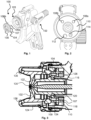
- the part of a spray gun 100 in particular a paint spray gun, according to the prior art shown in FIG. 1, comprises a base body 102 with various attachments. Shown is an air distribution ring 104, which can be arranged on the head region 103 of the base body 102.
- the air distribution ring 104 has at least one, in the present example two, retaining pins 106a and 106b, which are inserted into two blind holes 108a and 108b corresponding to the retaining pins 106a and 106b, which are in Fig.
- FIG. 2 are shown, in order to fasten the air distribution ring 104 to the gun head or to the head area 103 of the base body 102 in such a way that the wall 107 of the air distribution ring 104 lies sealingly against the front surface 110 of the head area 103 of the base body 102, which in Fig. 3 shown.
- the Fig. 3 The head portion 103 shown is disclosed in Chinese utility model ZL 2016 2 0911120.1.
- An atomizing air outlet opening 114 in the front surface 110 of the head portion 103 of the base body 102 lies within the wall 107 of the air distribution ring 104. Atomizing air flows from the atomizing air outlet opening 114 into an inner air distribution chamber 116, which is formed by the air distribution ring 104 and the base body 102.
- a horn air outlet opening 112 in the front surface 110 of the head region 103 of the base body 102 lies outside the wall 107 of the air distribution ring 104. Horn air flows from the horn air outlet opening 112 into an outer air distribution chamber 118 of the air distribution ring 104.
- the air distribution ring 104 On a surface within the wall 107, the air distribution ring 104 has a plurality of passages 120 distributed over its circumference, through which the atomizing air flows from the inner air distribution chamber 116. From the passages 120, the atomizing air flows to a plate 124 arranged integrally on the paint nozzle 122, which sealingly rests against a wall 109 of the air distribution ring 104, wherein the wall 109 is arranged on the side of the air distribution ring 104 facing away from the front surface 110 of the head region 103 of the base body 102.
- the plate 124 has a plurality of through-bores 126 distributed over its circumference. The air flowing through the through-holes 126 then flows through an annular gap 130 between the central opening of the air cap 132 and the front end of the paint nozzle 122, which may be designed in the form of a suppository.
- the outer air distribution chamber 118 of the air distribution ring 104 together with an outer wall 134 on the head region 103 of the base body 102, forms a gap through which the horn air flows from the outer air distribution chamber 118. From there, the air flows into the horn air supply channels in the air cap 132 and then into the horn air bores 136, from whose openings the air exits.
- Fig. 4 shows an exploded view of an embodiment of a spray gun 1 according to the invention.
- the spray gun 1 can have a cup 3 for receiving and dispensing the material to be sprayed, wherein the cup comprises a lid 3b with a valve plug 3a, a cup body 3c, and a plug-in sieve 3d.
- the spray gun 1 can comprise a material quantity regulator 11, an air micrometer 13, a round-to-wide jet regulator 9, a trigger system 7 consisting of a trigger and fastening means, and an air connection, which can be designed as a standard connection 4a or a swivel connection 4b.
- a nozzle arrangement consisting of a nozzle 24, which can comprise a material nozzle 40, can be arranged on the head region 6 of the base body 2.
- the nozzle arrangement can also comprise an air cap 76, which can be fastened to the head region 6 via an air nozzle ring 74. in particular screwable.
- the head region 6, the nozzle 24, and the air cap 76 with air nozzle ring 74 are arranged or can be arranged coaxially along an axis Z, which in the present case represents the above-mentioned central or longitudinal axis of the head region 6 of the base body 2, the central or longitudinal axis of the material nozzle 40, the central or longitudinal axis of the upper part of the base body 2 and the central or longitudinal axis of a receiving opening for receiving the material quantity regulating device 11.
- Fig. 5 is a sectional view of the embodiment of a base body 2 for a spray gun from Fig. 4 shown, with the section from top to bottom through the Z axis consisting of Fig. 4
- the base body 2 has a plurality of bores; in the upper part of the base body 2, in particular, a plurality of bores along an axis Z, which in the present case represents the above-mentioned central or longitudinal axis of the head region 6 of the base body 2.
- this axis is the same as the central or longitudinal axis of the material nozzle 40 arranged in or on the base body 2.
- the term along an axis refers to the Z axis.
- the middle wall 12 is clearly set back from the outer wall 14.
- the "front” is considered to be the spray direction or the side of the base body 2 on which the material nozzle 40 is Fig. 4 can be arranged, the opposite side or opposite direction, here the side with the receiving opening 82, is referred to as "rear".
- the fact that the front end of the middle wall 12 is "set back" along an axis Z relative to the front end of the outer wall 14 means that the front end of the outer wall 14 is further forward than the front end of the middle wall 12.
- the inner wall 10 is only slightly set back from the middle wall 12.
- FIG. 5 Only a single atomizing air duct 64 is visible, along with a horn air duct 66, which intersects with a second horn air duct.
- the sectional view also shows part of a round, wide-jet air distribution chamber 68.
- Fig. 6 shows a sectional view of a part of the embodiment of a base body 2 for a spray gun 1, which in Fig. 5 shown in a different sectional view.
- the Fig. 6 The section shown was again taken through the Z axis from Fig. 4 , but along a cutting plane which corresponds to the Fig. 5 applied cutting plane.
- the inner wall 10 of the head region 6 of the base body 2 of the spray gun 1 is set back from the middle wall 12 by a distance d4 along the Z axis.
- the middle wall 12 in turn, is set back from the outer wall 14 by a distance d3 along the Z axis.
- the outer wall 14 projects beyond the middle wall 12, which in turn projects beyond the inner wall 10.
- the inner wall 10 and the outer wall 12 delimit a first air distribution chamber 60
- the middle wall 12 and the outer wall 14 delimit a second air distribution chamber 62.
- the air distribution chambers 60 and 62 are open; towards the rear, they are delimited at least in regions by a first front surface 16 and a second front surface 18, respectively.
- a groove 19 is introduced into the second front surface 18, the bottom surface of which partially delimits the air distribution chamber 62 to the rear instead of the second front surface 18.
- the air distribution chamber 62 is therefore partially delimited to the rear by the second front surface 18 and partially by the bottom surface of the groove 19.
- the distance d5 i.e. the depth of the groove 19, i.e.
- the distance between the second front surface 18 and the bottom surface of the groove 19, can be, for example, approximately 1.5 mm to 3.0 mm.
- the distance d1 between the first front surface 16 and the front end of the outer wall 14 is preferably between 8 mm and 12 mm, particularly preferably between 9 mm and 11 mm.
- the distance d2 between the second front surface 18 and the front end of the outer wall 14 is preferably between 4 mm and 6 mm.
- the middle wall 12 is set back from the outer wall 14 along the axis Z by a distance d3, which is preferably approximately 2 mm to 4 mm.
- the inner wall 10 is preferably set back from the middle wall 12 by only 0.1 mm to 1.0 mm. This is the distance d4.
- the embodiment of a head region 6 of a base body shown has a counter sealing surface 84 for a Fig. 6 nozzle seal (not shown).
- the distance d6 between this counter sealing surface 84 and the first front surface 16 is preferably approximately 1.5 mm to 3.0 mm.
- the first front surface 16 is set back from the second front surface 18 along the Z axis.
- the distance d7 by which the front surface 16 is set back from the second front surface 18 is approximately 4 mm to 6 mm.
- the dimensions or combinations of dimensions mentioned have proven advantageous for good atomization quality in spray tests.
- Fig. 7 is a perspective view of a part of the embodiment of a base body 2 from Fig. 5 and Fig. 6 shown.
- the width of the groove 19 is approximately the same as the second front surface 18.
- the width of the groove 19 or the second front surface 18 refers to the extension in the radial direction of the head region 6 of the The distance between the central wall 12 and the outer wall 14 in the radial direction is to be understood as the distance between the central wall 12 and the outer wall 14.
- the groove 19 extends over approximately 50% of the circumference of the second front surface 18, i.e., in this case, over approximately 180%.
- the inner wall 10, the middle wall 12 and the outer wall 14 are each circular and arranged concentrically to each other and coaxially to the axis Z from the previous drawings.
- the axis Z runs through the axis of rotation of the walls, the walls run parallel to the axis Z.
- the inner wall 10 has an internal thread 70 in this case, into which a Fig. 7 A nozzle (not shown), in particular a material nozzle, which is often also referred to as a paint nozzle, can be screwed in.
- the outer wall 14 has an external thread 72, via which a Fig. 7 An air nozzle ring (not shown) with an air cap can be screwed onto the head region 6 of the base body 2.
- the middle wall 12 has no thread in the present case.
- the middle wall 12 can also have an internal or external thread.
- the outer wall 14 has an internal thread for screwing in a component, in particular an air cap
- the inner wall 10 has an external thread for screwing on a component, in particular a nozzle.
- the first front surface 16 has two inner air outlet openings 20a and 20b
- the second front surface 18 has two outer air outlet openings 22a and 22b.
- the diameter of the air outlet openings 20a, 20b, 22a, and 22b corresponds almost to the width of the front surfaces 16, 18 or the groove 19 into which they are inserted. This allows the available space to be utilized for maximum air throughput.
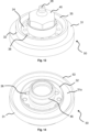
- Fig. 8 shows a perspective view of an embodiment of a nozzle 24 for use in an embodiment of a spray gun according to the invention or also for use in a method according to the invention.
- the nozzle 24 can have at least one material nozzle 40 with a material outlet opening 28 and a section for applying a tool, in this case an external hexagon profile 41, as well as a disk element 32 with a front surface 34 and a conical surface 35.
- the front surface 34 has in this case several, preferably 7 to 9, through openings 36 distributed over the circumference.
- Material nozzle 40 and disk element 32 are preferably designed as one piece.
- a first baffle plate 30 Arranged thereon, preferably captively arranged, particularly preferably pressed on, is a first baffle plate 30.
- a Fig. 9 This is arranged on the side of the first baffle plate 30 facing away from the material outlet opening 28.
- the second baffle plate 42 is also annular with an inner and an outer circumference. In the radial direction, the The inner circumference of the second baffle plate 42 does not extend to the external thread 46 of the material nozzle 40, so that a gap exists between the inner circumference of the second baffle plate 42 and the external thread 46 of the material nozzle 40.
- the second baffle plate 42 is spaced from the through-openings 36. In the radial direction, the second baffle plate 42 almost completely covers the through-openings 36, as shown in Fig. 10 is clearly visible. In Fig. 10 Also visible are the material outlet opening 28 and the impact surface 30a of the first impact plate 30.
- the plate element 32 has a recess or groove on its side facing away from the material outlet opening 28, in which the through-openings 36 are arranged. This increases the distance between the side of the plate element 32 facing away from the material outlet opening 28 and the side of the second impact plate 42 facing this side, and the air flowing into this area has more volume available for distribution.
- Fig. 11 shows the structure of the nozzle 24 in a sectional view. It can be seen that the material nozzle 40 with its material outlet opening 28 and the disk element 32 are designed as a single piece. On its side facing away from the material outlet opening 28, the disk element 32 has a circumferential groove 33 which enables or facilitates the pressing of the first baffle plate 30 onto the disk element 32.
- the first baffle plate 30 has an inner circumference and an outer circumference, wherein the outer circumference of the first baffle plate 30 is larger than the outer circumference of the disk element 32.
- the inner circumference of the first baffle plate 30 extends approximately as far as the through-openings 36 of the disk element 32.
- the second baffle plate 42 is arranged as a single piece on the first baffle plate 30.
- a collar 43 can be arranged between them.
- the first baffle plate 30 can have a recess on its side facing the material outlet opening 28, particularly in the region of the inner circumference, so that a stepped shape is formed, which can form the contact area between the first baffle plate 30 and the plate element 32.
- the plate element 32 also has a step on its side facing away from the material outlet opening 28, particularly in the region of the outer circumference, which forms the contact area between the first baffle plate 30 and the plate element 32.
- the material nozzle 40 is equipped with an air guide disc 38, which is also captively connected to the material nozzle 40, in particular, it can be pressed on. Furthermore, the present nozzle 24 has a nozzle seal 44, the purpose of which is explained further below.
- the nozzle seal 44 is preferably made of plastic and is preferably replaceably connected to the material nozzle 40. In Fig. 11 the external thread 46 of the material nozzle 40 is also indicated.
- Fig. 12 shows a sectional view of the head region 6 of an embodiment of a spray gun according to the invention with the embodiment of a nozzle 24 from Fig. 8 to Fig. 11 in the assembled state.
- the nozzle 24, which in this case is a unit comprising the material nozzle 40 with the disc element 32, the first baffle plate 30, the second baffle plate 42, the air guide plate 38, and the nozzle seal 44, is screwed into the base body or its head region via the threads described above.
- the stop is formed by the first baffle plate 30, in particular its baffle surface 30a, and the central wall 12 of the head region 6 of the base body.
- the baffle surface 30a of the first baffle plate 30 acts as a sealing surface, and the central wall 12, in particular the front end of the central wall 12, acts as a counter-sealing surface against which the baffle surface 30a bears in a sealing manner.
- the outer surface of the second baffle plate 42 or the outer surface of the collar 43 between the first baffle plate 30 and the second baffle plate 42 can also be in sealing contact with an inner surface of the central wall 12.
- the nozzle seal 44 is against a counter sealing surface 84 which is Fig. 6 shown, presses and seals the material-carrying area of the spray gun, in particular the transition area between the paint channel in the base body and the hollow section of the material nozzle 40 for conveying the material to be sprayed, against the air-carrying area of the spray gun.
- the first baffle plate 30 forms a gap 86 with the outer wall 14, which preferably represents an annular gap with a substantially constant width.
- the second baffle plate 42 forms a further gap 88 with the inner wall 10, which also preferably represents an annular gap with a substantially constant width.
- the air nozzle ring 74 can be arranged on the head region 6 of the base body via the threads already mentioned above.
- the air cap 78 is arranged in the air nozzle ring 74, wherein the air cap 78 is fixed in a first direction by means of a flange 90, which rests against a projection on the inner surface of the air nozzle ring 74.
- the air cap 78 is limited by a retaining ring 89, which lies in a groove 91 in the air cap 78 and in a recess in the inner surface of the air nozzle ring 74.
- the retaining ring 89 is shown in the present Fig. 12 outside the groove 91, whereby the retaining ring 89 does not have to be completely located in the groove 91.
- the retaining ring 89 can be polygonal in shape so that it only partially lies in the circular groove 91.
- the first front surface 16 between the inner wall 10 and the middle wall 12 and the second front surface 18 between the middle wall 12 and the outer wall 14 in the present embodiment of the base body each have two air outlet openings 20a and 20b and 22a and 22b respectively.
- the air flowing out of the two inner air outlet openings 20a and 20b between the inner wall 10 and the middle wall 12 first strikes the second baffle plate 42. Due to the constriction in the form of the gap 88, the air is distributed over the circumference of the air distribution chamber between the inner wall 10 and the middle wall 12. The air flows through the gap 88 and is thereby throttled before flowing through the through-openings 36 of the plate element 32.
- the air exiting the through-openings 36 in a somewhat "punctuated" manner strikes the air guide element 38, whereby the air is distributed more evenly, homogenized, and slightly throttled again by the slight constriction between the air guide element 38 and the inner surface of the air cap 78. From the air cap chamber 80 between the air cap 78 and the material nozzle 40, the air then flows through a gap, in particular an annular gap, which is created by the front end of the material nozzle 40 protruding from the inside into the central opening 79 in the air cap 78.
- the air with the path just described is therefore referred to as atomizing air.
- the two inner air outlet openings 20a and 20b between the inner wall 10 and the middle wall 12 can be referred to as atomizing air outlet openings, the air channels behind them as atomizing air channels, and the air distribution chamber delimited by the inner wall 10 and the middle wall 12 can be referred to as the atomizing air distribution chamber.
- the area through which the atomizing air flows can be referred to as the atomizing air area.
- the air flowing from the two outer air outlet openings 22a and 22b, which are located in the Fig. 12 shown embodiment of the base body is present, but in Fig. 7 can be seen particularly well, the escaping air first hits the first baffle plate 30. Due to the constriction in the form of the gap 86, the air is distributed over the circumference of the air distribution chamber between the middle wall 12 and the outer wall 14. The air flows through the gap 86 and is thereby throttled.
- the air then flows into an intermediate chamber 92 and into the horn air supply channels 78a in the horns of the air cap 78. From here, the air flows out of the horn air holes 78b and hits the above-mentioned spray jet, deforming it.
- the so-called horn air flowing out of the horn air holes 78b in the diametrically opposed horns of the air cap 78 pushes the spray jet, which originally had a circular cross-section, on two opposite sides, creating a so-called wide jet.
- the amount of horn air flowing out of the horn air holes 78b, or even the amount of air flowing out of the outer air outlet openings 22a and 22b, which can be referred to as horn air outlet openings can be controlled by a control device shown in Fig. 4
- the round-wide jet control device 9 shown can be adjusted. If the horn air is reduced to zero or almost zero, the spray gun produces a so-called round jet with a circular cross-section.
- the air channels behind the so-called horn air outlet openings can be referred to as horn air channels
- the air distribution chamber defined by the central wall 12 and the outer wall 14 can be referred to as the horn air distribution chamber
- the area through which the horn air flows can be referred to as the horn air area.
- a sealing element 87 can be provided between the air nozzle ring 74 and the head area 6.
- control openings 79a can be incorporated into the front surface of the air cap 78, radially outside of the central opening 79.
- the air exiting the control openings 79a influences the horn air, in particular, it mitigates the impact of the horn air on the spray jet.
- the so-called control air protects the air cap 78 from contamination by carrying paint droplets away from the air cap 78. It also contributes to the further atomization of the spray jet.
- the control air also acts on the circular jet, causing a slight pre-deformation and, here too, additional atomization.
- the separation, in particular the sealing, between the atomizing air region and the horn air region is achieved by the central wall 12, the first baffle plate 30, the plate element 32 and by the air cap 78, in particular by a preferably circumferential web 78c of the air cap 78.
- the web 78c in this case has a conical region which bears against the conical surface 35 of the plate element 32. This also centers the air cap 78, ensuring that the air cap 78 and the material nozzle 40 are arranged concentrically to one another and that the above-mentioned gap, in particular the annular gap, between the front end of the material nozzle 40 and the air cap 78 for the outlet of the atomizing air has a constant width.
- the nozzle 24 shown is preferably a low-pressure or HVLP nozzle, or a nozzle for use in a low-pressure or HVLP nozzle arrangement, in particular for use in a method according to the invention for converting a spray gun, in particular a paint spray gun.
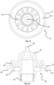
- Fig. 13 shows a perspective view of a second embodiment of a nozzle for use in an embodiment of a spray gun according to the invention or also for use in a method according to the invention.
- the present nozzle 50 does not have an air guide disk, and the disk element 32 has a larger number of through-openings 36 in the front surface 34.
- the nozzle 50 also has a material nozzle 40 with a material outlet opening 28, and the disk element 32 has a conical surface 35.
- the disk element 32 has a recess or groove on its side facing away from the material outlet opening 28, in which the through-openings 36 are arranged.
- first baffle plate 31 of the nozzle 50 is designed differently than the first baffle plate 30 of the previously described nozzle 24.
- the nozzle 50 does not have a second baffle plate, but instead has an inner collar 52 and an outer collar 53 with an intermediate baffle surface 31a.
- Fig. 15 which shows a rear view of the nozzle 50, it is clear that the through-openings 36 are completely exposed, i.e., they are not covered or overhanging other components of the nozzle 50.
- the disc element 32 of the nozzle 50 preferably has a larger number of through-openings 36, in particular between 10 and 14.
- the exposed through openings 36 are also in Fig. 16 which is a sectional view of the nozzle 50.
- the material nozzle 40 with integrally arranged disc element 32 and preferably replaceable arranged nozzle seal 44 is essentially identical to the material nozzle 40 with integrally arranged disc element 32 and preferably replaceable arranged Nozzle seal 44 of the previously described nozzle 24.
- the above statements regarding these components apply accordingly to the nozzle 50.
- the first baffle plate 31 with inner collar 52, outer collar 53, and intermediate baffle surface 31a differs from the first baffle plate 30 of the previously described nozzle 24.
- Fig. 17 shows a sectional view of the head region 6 of an embodiment of a spray gun according to the invention with the embodiment of a nozzle 50 from the Figs. 13 to 16
- the basic body is the Fig. 12 shown embodiment.
- the head region 6 is designed the same, which is why reference can be made to the above explanations. It can be seen that the gap 86 between the outer wall 14 and the first baffle plate 31 is narrower than the gap 86 from Fig. 12 , which shows the head region 6 of the base body equipped with the previously described nozzle 24.
- the atomizing air is directed in the Fig. 17 shown arrangement, ie when using the nozzle 50, is less throttled than in the Fig. 12 shown arrangement, ie when using the nozzle 24.
- the nozzle internal pressure ie in particular the pressure in the air cap chamber 81 between the air cap 78 and the material nozzle 40 when using the nozzle 50 is greater than the nozzle internal pressure, ie in particular the pressure in the Fig. 12 shown air cap chamber 80 between air cap 78 and material nozzle 40 when using nozzle 24.
- the nozzle 50 shown is preferably a high-pressure or compliant nozzle, or a nozzle for use in a high-pressure or compliant nozzle arrangement, in particular for use in a method according to the invention for converting a spray gun, in particular a paint spray gun, with a first internal nozzle pressure to a spray gun, in particular a paint spray gun, with a second internal nozzle pressure.
- Fig. 18 is a perspective view of a part of an embodiment of a base body, namely the area in which a Fig. 4
- the circular wide-jet regulating device 9 shown as an example can be arranged.
- the interior of the round-wide jet air distribution chamber 68 is at least partially visible.
- the base body 2, as in Fig. 7 visible, at the head area 6 each have two atomizing air outlet openings 20a, 20b and two horn air outlet openings 22a, 22b.
- the two atomizing air outlet openings 20a, 20b are spaced apart from each other, as are the two horn air outlet openings 22a, 22b.
- the round wide jet air distribution chamber 68 therefore has only a single atomizing air duct opening 20c.
- the round wide jet air distribution chamber 68 therefore also has only a single horn air duct opening 22c.
- the outer contours of the atomizing air duct opening 20c and the horn air duct opening 22c in the round, wide-jet air distribution chamber 68 can have the outer contour of a horizontal figure-8.
- the atomizing air duct opening 20c has substantially the same cross-sectional shape as at least one of the atomizing air outlet openings 20a and 20b
- the horn air duct opening 22c has substantially the same cross-sectional shape as one of the horn air outlet openings 22a, 22b.
- the round-wide jet air distribution chamber 68 has a first chamber section and a second chamber section, wherein the second chamber section has a larger diameter than the first chamber section.
- the horn air ducts of the base body 2 open into the first chamber section, i.e., the horn air duct opening 22c is located in the first chamber section.
- the atomizer air ducts of the base body 2 open into the second chamber section, i.e., the atomizer air duct opening 20c is located in the second chamber section.
- the sections form a step onto which a plate of a round-wide jet regulating device can be placed in order to close the first chamber section and thus the air supply to the Horn air duct opening 22c and thus into the horn air ducts.
- the spray gun when the spray gun is in operation, only the atomizing air duct opening 20c and thus the atomizing air ducts are supplied with air.
- the spray gun produces a round jet with an essentially circular cross-section, since no horn air acts laterally on the spray jet.
- the plate of the round-wide jet regulating device can preferably be continuously moved away from the step between the first and second chamber sections of the round-wide jet air distribution chamber 68, so that the plate releases the air supply to the first chamber section and thus to the horn air duct opening 22c and to the horn air ducts in the base body 2.
- the further the plate is moved away from the step the more air can flow through the horn air ducts and thus out of the horn air bores, and the more the spray jet is compressed laterally, creating an increasingly narrow wide jet.
Landscapes
- Nozzles (AREA)
Description
- Die Erfindung betrifft eine Spritzpistole, insbesondere Farbspritzpistole, gemäß dem Oberbegriff des Anspruchs 1, ein Verfahren zum Umrüsten einer Spritzpistole, insbesondere Farbspritzpistole, gemäß dem Oberbegriff des Anspruchs 11 und ein Verfahren zum Umrüsten einer Spritzpistole, insbesondere Farbspritzpistole, gemäß dem Oberbegriff des Anspruchs 13.
- Gemäß dem Stand der Technik weist eine Spritzpistole, insbesondere Farbspritzpistole, insbesondere druckluftzerstäubende Farbspritzpistole, an ihrem Kopf eine Farbdüse auf, welche in den Pistolenkörper eingeschraubt wird. Die Farbdüse weist an ihrem vorderen Ende häufig ein hohlzylindrisches Zäpfchen auf, aus deren vorderer Mündung beim Betrieb der Spritzpistole das zu verspritzende Material austritt. Die Farbdüse kann in ihrem vorderen Bereich jedoch auch konisch ausgestaltet sein. Der Pistolenkopf weist in der Regel ein Außengewinde auf, über das ein Luftdüsenring mit einer darin angeordneten Luftkappe am Pistolenkopf angeschraubt wird. Die Luftkappe weist eine zentrale Öffnung auf, deren Durchmesser größer ist als der Außendurchmesser des Farbdüsenzäpfchens bzw. der Außendurchmesser des vorderen Ende einer konischen Farbdüse. Die zentrale Öffnung der Luftkappe und das Zäpfchen bzw. das vordere Ende der Farbdüse bilden zusammen einen Ringspalt. Aus diesem Ringspalt tritt die sogenannte Zerstäuberluft aus, welche in der oben beschriebenen Düsenanordnung ein Vakuum an der Stirnfläche der Farbdüse erzeugt, wodurch das zu verspritzende Material aus der Farbdüse herausgesaugt wird. Die Zerstäuberluft trifft auf den Farbstrahl, wodurch der Farbstrahl in Fäden und Bänder zerrissen wird. Diese Fäden und Bänder zerfallen aufgrund ihrer hydrodynamischen Instabilität, der Wechselwirkung zwischen der schnell strömenden Druckluft und der Umgebungsluft sowie aufgrund von aerodynamischen Störungen zu Tröpfchen, welche durch die Zerstäuberluft von der Düse weg geblasen werden.
- Die Luftkappe weist häufig ferner zwei Hörner auf, welche einander diametral gegenüberstehen und in Ausströmrichtung über den genannten Ringspalt und die Materialauslassöffnung hinausstehen. Von der Rückseite der Luftkappe verlaufen zwei Versorgungsbohrungen, d.h. Hornluftzuführkanäle, zu Hornluftbohrungen in den Hörnern. In der Regel weist jedes Horn zumindest eine Hornluftbohrung auf, bevorzugt weist jedes Horn jedoch zumindest zwei Hornluftbohrungen auf, aus welchen die Hornluft austritt. Die Hornluftbohrungen sind in der Regel so orientiert, dass sie auf die Düsenlängsachse in Austrittsrichtung nach dem Ringspalt zeigen, sodass die aus den Hornluftbohrungen austretende sogenannte Hornluft die bereits aus dem Ringspalt ausgetretene Luft bzw. den Farbstrahl oder den bereits zumindest teilweise entstandenen Farbnebel beeinflussen können. Dadurch wird der Farbstrahl oder auch Spritzstrahl mit ursprünglich kreisrundem Querschnitt (Rundstrahl) an seinen den Hörnern zugewandten Seiten zusammengedrückt und in senkrecht dazu stehender Richtung verlängert. Dadurch entsteht ein sogenannter Breitstrahl, welcher eine größere Flächenlackiergeschwindigkeit erlaubt. Neben der Verformung des Spritzstrahls bezweckt die Hornluft eine weitere Zerstäubung des Spritzstrahls.
- In den Pistolenkörper, d.h. den Grundkörper der Spritzpistole, sind in der Regel Luftkanäle eingebracht, wobei Luft aus einem der Kanäle, wie oben beschrieben, zur Verwendung als Zerstäuberluft zum genannten Ringspalt geleitet wird, und Luft aus einem anderen Kanal, wie oben beschrieben, zur Verwendung als Hornluft zu den genannten Hornluftöffnungen geleitet wird. Hierzu münden die Luftkanäle in einer Stirnfläche des Kopfs des Pistolenkörpers und werden über eine Luftverteiler-Anordnung zum Ringspalt bzw. zu den Hornluftbohrungen geleitet. Die Luftverteiler-Anordnung umfasst häufig einen Luftverteiler-Ring, der den Zerstäuberluftbereich und den Hornluftbereich voneinander trennt. Eine derartige Düsenanordnung bzw. Luftverteiler-Anordnung ist beispielsweise in der
DE 20 2010 012 449 U1 und in den chinesischen GebrauchsmusterschriftenZL 2014 2 0431026.7 ZL 2016 2 0911120.1 - Nachteilhaft am oben beschriebenen Stand der Technik, nämlich der Luftverteiler-Anordnung aufweisend einen Luftverteiler-Ring, ist, dass der Luftverteiler-Ring vom Hersteller der Spritzpistole als separates Bauteil hergestellt und vom Hersteller bzw. vom Benutzer der Spritzpistole montiert werden muss. Der Benutzer muss das separate Bauteil reinigen und wechseln. Ferner besteht das Risiko eines Verlusts des Luftverteiler-Rings, wodurch die Spritzpistole unbrauchbar wird bis der Benutzer Ersatz beschafft hat. Um eine einfache Abdichtung zwischen Zerstäuberluftbereich und Hornluftbereich zu erreichen, ist der Luftverteiler-Ring aus Kunststoff hergestellt. Dadurch ist er jedoch anfällig für Beschädigungen. Ferner sind die Luftverteiler-Ringe gemäß dem Stand der Technik relativ komplex ausgestaltet.
- Die
US 2007/0262169 A1 zitiert die taiwanesische GebrauchsmusterschriftTW 510253 - Sowohl die Pistolenkopfstruktur gemäß dem in der US-Schrift zitierten Stand der Technik, wie auch die in der genannten US-Schrift selbst beschriebene Anordnung umfasst eine Vielzahl an Einzelteilen mit den oben beschriebenen Nachteilen. Die einzelnen Komponenten sind teilweise relativ filigran ausgestaltet. Bei einer Beschädigung von einer der Komponenten besteht das Risiko, dass eine Abdichtung zwischen Zerstäuberluftbereich und Hornluftbereich bereits nicht mehr gegeben ist, was einen negativen Einfluss auf den Spritzstrahl hat. Ferner ist der Pistolenkopf aufgrund der Vielzahl an aufeinandergesetzten Komponenten relativ lang. Weiter zeigt die
US6612506B1 eine Spritzpistole und dieDE69827994T2 ein Verfahren zum Umrüsten einer Spritzpistole nach dem Stand der Technik. - Aufgabe der vorliegenden Erfindung ist es daher, eine Spritzpistole, insbesondere Farbspritzpistole, bereitzustellen, welche weniger anfällig für Beschädigungen und funktionssicher sind.
- Eine weitere Aufgabe der vorliegenden Erfindung ist es, Verfahren zum Umrüsten einer Spritzpistole, insbesondere Farbspritzpistole, bereitzustellen, mittels derer eine Spritzpistole, insbesondere Farbspritzpistole, mit einem ersten Düseninnendruck einfach zu einer Spritzpistole, insbesondere Farbspritzpistole, mit einem zweiten Düseninnendruck und zurück umgerüstet werden kann.
- Die erste Aufgabe wird durch eine Spritzpistole, insbesondere Farbspritzpistole, gelöst, die zumindest einen Grundkörper, eine Düse mit zumindest einer Materialdüse, eine Luftkappe, einen ersten luftführenden Bereich und einen zweiten luftführenden Bereich aufweist, wobei der erste luftführende Bereich Luft führt, die zur Zerstäubung von zu verspritzendem Material verwendet wird, und der zweite luftführende Bereich Luft führt, die zur Beeinflussung eines Spritzstrahls verwendet wird, wobei der Grundkörper zumindest einen Kopfbereich zur Anbringung einer Düsenanordnung aufweist, wobei der Kopfbereich zumindest eine innere Wandung, eine äußere Wandung und eine dazwischen angeordnete mittlere Wandung aufweist, wobei die Wandungen umlaufend und einstückig mit dem Grundkörper ausgebildet sind, wobei das vordere Ende der mittleren Wandung entlang einer Achse gegenüber dem vorderen Ende der äußeren Wandung zurückgesetzt ist, wobei der erste luftführende Bereich und der zweite luftführende Bereich zumindest bereichsweise durch die mittlere Wandung des Grundkörpers, ein an der Materialdüse einstückig angeordnetes Scheibenelement, zumindest eine an der Materialdüse angeordnete, insbesondere unverlierbar angeordnete, Prallscheibe und durch zumindest einen Teil der Luftkappe voneinander separiert sind, und wobei die innere Wandung, die mittlere Wandung und die äußere Wandung jeweils kreisrund ausgestaltet und konzentrisch zueinander angeordnet sind. Durch die beschriebene Ausgestaltung ist eine Trennung bzw. Abdichtung zwischen dem ersten und dem zweiten luftführenden Bereich nur mit bereits vorhandenen Teilen, d.h. Teilen, die auch eine andere Funktion als die Trennung der beiden Bereiche erfüllen, möglich. Es ist kein zusätzliches Dichtelement nötig, wodurch die Anzahl der Einzelteile niedrig gehalten werden kann, um die oben genannten Nachteile zu überwinden bzw. die oben genannten Vorteile zu realisieren.
- Die Luft, die zur Zerstäubung von zu verspritzendem Material verwendet und von dem ersten luftführenden Bereich geführt wird, wird häufig als Zerstäuberluft bezeichnet. Die Luft, die zur Beeinflussung eines Spritzstrahls verwendet und von dem zweiten luftführenden Bereich geführt wird, wird häufig als Hornluft bezeichnet. Die Bereiche werden häufig als Zerstäuberluftbereich bzw. Hornluftbereich bezeichnet. Das Scheibenelement kann als Teil der Materialdüse angesehen werden, sodass eine eigentlich am Scheibenelement angeordnete Prallscheibe auch als an der Materialdüse angeordnet angesehen werden kann. Dass die Prallscheibe "unverlierbar" an der Materialdüse angeordnet ist, bedeutet vorliegend, dass die Prallscheibe nicht oder nicht ohne größere Anstrengung von der Materialdüse entfernt werden kann und das Entfernen nicht vorgesehen ist. Beispielsweise kann die Prallscheibe mit der Materialdüse verpresst, verklebt, vernietet oder verschweißt sein. Auch eine starke Schnappverbindung oder ein starkes Verschrauben kann die Prallscheibe "unverlierbar" machen.
- Die am Kopfbereich anbringbare Düsenanordnung kann beispielsweise eine Materialdüse, welche häufig auch als Farbdüse bezeichnet wird, und zumindest dem Auslass des zu verspritzenden Materials dient, eine Luftkappe zum Auslass von Luft und einen Luftdüsenring zum Verbinden der Luftkappe mit dem Grundkörper umfassen.
- Als Wandung kann vorliegend insbesondere ein Steg oder eine Trennwand mit einer Dicke von einigen Millimetern verstanden werden, die sich im Wesentlichen parallel zur Zentral- bzw. Längsachse des Kopfbereichs des Grundkörpers bzw. zur Zentral- bzw. Längsachse der in oder am Grundkörper anordenbaren Materialdüse erstreckt. Es kann sich dabei auch um eine Zentral- bzw. Längsachse eines oberen Teils des Grundkörpers und/oder um die Zentral- bzw. Längsachse einer Aufnahmeöffnung zur Aufnahme einer Materialmengenreguliereinrichtung handeln. Die Wandung steht vorzugsweise im Wesentlichen senkrecht auf einer Fläche, beispielsweise einer Frontfläche des Kopfes des Grundkörpers, welche im Wesentlichen senkrecht zu der bzw. den oben genannten Zentral- bzw. Längsachsen verläuft. Die Bezeichnungen "innere", "mittlere" und "äußere" Wandung sind derart zu verstehen, dass in der Ansicht von vorne auf den Pistolenkopf die innere Wandung in radialer Richtung dem Mittelpunkt des Pistolenkopfes näher ist als die mittlere Wandung, welche dem Mittelpunkt des Pistolenkopfes wiederum näher ist als die äußere Wandung.
- Die Wandungen sind kreisrund ausgestaltet und haben vorzugsweise eine konstante Dicke.
- Die Bezeichnung "einstückig" mit dem Grundkörper ausgebildet bedeutet vorliegend, dass die Wandungen und der restliche Grundkörper aus einem Stück gefertigt wurden, beispielsweise mittels Guss, spanender Bearbeitung, 3D-Druck oder sonstigen Verfahren.
- D.h. die Wandungen und der Grundkörper müssen nicht getrennt voneinander gefertigt und anschließend miteinander verbunden werden. Dadurch kann die Anzahl der Einzelteile reduziert werden. Besonders bevorzugt wird der Grundkörper zunächst aus einem gebogenen Vollmaterialstab geschmiedet und anschließend mittels Bohrer, Fräser oder einer Kombination aus diesen bearbeitet.
- Unter "entlang einer Achse" ist vorliegend entlang der Zentral- bzw. Längsachse des Kopfbereichs des Grundkörpers bzw. der Zentral- bzw. Längsachse des in oder am Grundkörper anordenbaren Materialdüse zu verstehen. Als "vorne" wird dabei die Spritzrichtung bzw. die Seite des Grundkörpers angesehen an dem die Materialdüse angeordnet oder anordenbar ist, als "hinten" die Gegenseite bzw. Gegenrichtung, an der beispielsweise eine Materialmengenreguliereinrichtung angeordnet bzw. anordenbar ist.
- Die oben letztgenannte Aufgabe wird durch ein Verfahren zum Umrüsten einer Spritzpistole, insbesondere Farbspritzpistole, mit einem ersten Düseninnendruck zu einer Spritzpistole, insbesondere Farbspritzpistole, mit einem zweiten Düseninnendruck, gelöst, wobei der erste Düseninnendruck größer ist als der zweite Düseninnendruck, wobei das Verfahren insbesondere als einen Schritt das Entfernen einer Hochdruck-Düsenanordnung von oder aus einem Grundkörper der Spritzpistole umfasst, wobei die Hochdruck-Düsenanordnung zumindest eine Düse mit einer Materialdüse mit einem hohlen Abschnitt zur Durchleitung des zu verspritzenden Materials und einer Materialauslassöffnung aufweist, und wobei das Verfahren als einen weiteren Schritt das Anordnen einer Niederdruck-Düsenanordnung in oder an dem Grundkörper der Spritzpistole umfasst, wobei die Niederdruck-Düsenanordnung zumindest eine Düse mit einer Materialdüse mit einem hohlen Abschnitt zur Durchleitung des zu verspritzenden Materials und einer Materialauslassöffnung aufweist, wobei die Düse der Hochdruck-Düsenanordnung, welche von oder aus dem Grundkörper der Spritzpistole entfernt wird, ferner ein am äußeren Umfang des hohlen Abschnitts angeordnetes Scheibenelement und zumindest eine erste Prallscheibe aufweist, wobei die erste Prallscheibe an der der Materialauslassöffnung abgewandten Seite des Scheibenelements angeordnet ist und einen inneren und einen äußeren Umfang aufweist, und wobei die Düse der Niederdruck-Düsenanordnung, welche in oder an dem Grundkörper der Spritzpistole angeordnet wird, ferner ein am äußeren Umfang des hohlen Abschnitts angeordnetes Scheibenelement und zumindest eine erste Prallscheibe aufweist, wobei die erste Prallscheibe an der der Materialauslassöffnung abgewandten Seite des Scheibenelements angeordnet ist, einen inneren und einen äußeren Umfang aufweist, und eine sich an der der Materialauslassöffnung abgewandten Seite der ersten Prallscheibe angeordnete zweite Prallscheibe aufweist, wobei der äußere Umfang der ersten Prallscheibe der Düse der Niederdruck-Düsenanordnung kleiner ist als der äußere Umfang der ersten Prallscheibe der Düse der Hochdruck-Düsenanordnung.
- Die Aufgabe wird ferner durch ein Verfahren zum Umrüsten einer Spritzpistole, insbesondere Farbspritzpistole, mit einem ersten Düseninnendruck zu einer Spritzpistole, insbesondere Farbspritzpistole, mit einem zweiten Düseninnendruck gelöst, wobei der erste Düseninnendruck kleiner ist als der zweite Düseninnendruck, wobei das Verfahren insbesondere als einen Schritt das Entfernen einer Niederdruck-Düsenanordnung von oder aus einem Grundkörper der Spritzpistole umfasst, wobei die Niederdruck-Düsenanordnung zumindest eine Düse mit einer Materialdüse mit einem hohlen Abschnitt zur Durchleitung des zu verspritzenden Materials und einer Materialauslassöffnung aufweist, und wobei das Verfahren als einen weiteren Schritt das Anordnen einer Hochdruck-Düsenanordnung in oder an dem Grundkörper der Spritzpistole umfasst, wobei die Hochdruck-Düsenanordnung zumindest eine Düse mit einer Materialdüse mit einem hohlen Abschnitt zur Durchleitung des zu verspritzenden Materials und einer Materialauslassöffnung aufweist, wobei die Düse der Niederdruck-Düsenanordnung, welche von oder aus dem Grundkörper der Spritzpistole entfernt wird, ferner ein am äußeren Umfang des hohlen Abschnitts angeordnetes Scheibenelement und zumindest eine erste Prallscheibe aufweist, wobei die erste Prallscheibe an der der Materialauslassöffnung abgewandten Seite des Scheibenelements angeordnet ist, einen inneren und einen äußeren Umfang aufweist, und eine sich an der der Materialauslassöffnung abgewandten Seite der ersten Prallscheibe angeordnete zweite Prallscheibe aufweist, und wobei die Düse der Hochdruck-Düsenanordnung, welche in oder an dem Grundkörper der Spritzpistole angeordnet wird, ferner ein am äußeren Umfang des hohlen Abschnitts angeordnetes Scheibenelement und zumindest eine erste Prallscheibe aufweist, wobei die erste Prallscheibe an der der Materialauslassöffnung abgewandten Seite des Scheibenelements angeordnet ist und einen inneren und einen äußeren Umfang aufweist, wobei der äußere Umfang der ersten Prallscheibe der Düse der Hochdruck-Düsenanordnung größer ist als der äußere Umfang der ersten Prallscheibe der Düse der Niederdruck-Düsenanordnung.
- Spritzpistolen, insbesondere Farbspritzpistolen, arbeiten mit verschiedenen Druckverfahren. Konventionelle Spritzpistolen arbeiten mit relativ hohen Spritzdrücken von mehreren Bar. Bei sogenannten HVLP-Pistolen liegt der Düseninnendruck bei maximal 10 psi oder 0,7 bar, wodurch Übertragungsraten von weit mehr als 65 % erreicht werden. Compliant-Spritzpistolen wiederum haben einen Düseninnenruck von mehr als 10 psi oder 0,7 bar, erreichen jedoch ebenfalls eine Übertragungsrate von mehr als 65 %.
- Gemäß dem Stand der Technik unterscheiden sich HVLP-Spritzpistolen strukturell insbesondere dadurch von Compliant-Spritzpistolen, dass in den Luftkanalmündungen im Kopf des Grundkörpers von HVLP-Spritzpistolen zusätzliche Drossel-Röhrchen eingesetzt sind. Dies macht zusätzliche Herstellungsschritte erforderlich und eine einmal als HVLP-Spritzpistole ausgestaltete Spritzpistole bzw. ein zur Verwendung für eine HVLP-Spritzpistole ausgestalteter Grundkörper kann nicht oder nur schwer zu einer Compliant-Spritzpistole bzw. zu einem Compliant-Spritzpistolen-Grundkörper umgerüstet werden, da die Drossel-Röhrchen fest in die Luftkanalmündungen eingebracht, beispielsweise eingepresst werden müssen, damit ein unbeabsichtigtes Lösen vermieden wird.
- Der Vorteil des ersten erfindungsgemäßen Verfahrens zum Umrüsten einer Spritzpistole, insbesondere Farbspritzpistole, mit einem ersten Düseninnendruck zu einer Spritzpistole, insbesondere Farbspritzpistole, mit einem zweiten Düseninnendruck, wobei der erste Düseninnendruck größer ist als der zweite Düseninnendruck, liegt darin, dass der Grundkörper der Spritzpistole unverändert bleiben kann, wenn beispielsweise eine Compliant-Spritzpistole zu einer HVLP-Spritzpistole umgerüstet werden soll. Die Spritzpistole kann einfach durch Austausch der Düse zu einer Spritzpistole mit geringerem Düseninnendruck umgerüstet werden. Auf die Herstellung separater Drossel-Röhrchen und deren Einbringen in den Grundkörper der Spritzpistole kann verzichtet werden.
- Der Vorteil des zweiten erfindungsgemäßen Verfahrens zum Umrüsten einer Spritzpistole, insbesondere Farbspritzpistole, mit einem ersten Düseninnendruck zu einer Spritzpistole, insbesondere Farbspritzpistole, mit einem zweiten Düseninnendruck, wobei der erste Düseninnendruck kleiner ist als der zweite Düseninnendruck, liegt ebenso darin, dass der Grundkörper der Spritzpistole unverändert bleiben kann, wenn beispielsweise eine HVLP-Spritzpistole zu einer Compliant-Spritzpistole umgerüstet werden soll. Die Spritzpistole kann einfach durch Austausch der Düse zu einer Spritzpistole mit höherem Düseninnendruck umgerüstet werden. Auf das schwierige Entfernen der in den Grundkörper der Spritzpistole eingebrachten Drossel-Röhrchen kann verzichtet werden.
- Bei beiden erfindungsgemäßen Verfahren zum Umrüsten einer Spritzpistole, insbesondere Farbspritzpistole, liegt ein weiterer Vorteil darin, dass das Umrüsten auch nach Auslieferung der Spritzpistole zum Kunden noch einfach möglich ist.
- Unter dem Düseninnendruck der Spritzpistole wird der Druck verstanden, welcher in der Luftkappe der Spritzpistole herrscht. Häufig ist dabei der Zerstäuberluftbereich vom Hornluftbereich separiert und im Zerstäuberluftbereich kann ein anderer Druck herrschen als im Hornluftbereich. Die Drücke im Zerstäuberluftbereich und im Hornluftbereich können jedoch auch gleich sein. Der Düseninnendruck kann beispielsweise mit Hilfe einer sogenannten Prüfluftkappe gemessen werden. Dabei handelt es sich um eine spezielle Luftkappe, welche anstelle der üblichen Luftkappe an der Spritzpistole angeordnet wird. Die Prüfluftkappe weist in der Regel zwei Manometer auf, wobei eines davon über eine Bohrung in der Prüfluftkappe mit dem Zerstäuberluftbereich und das andere über eine weitere Bohrung in der Prüfluftkappe mit dem Hornluftbereich verbunden ist.
- Die Bezeichnungen Niederdruck-Düsenanordnung und Hochdruck-Düsenanordnung sollen vorliegend nicht bedeuten, dass die jeweilige Düsenanordnung nur in klassischen Niederdruck- bzw. Hochdruck-Spritzpistolen Anwendung findet bzw. dass durch den Einsatz der jeweiligen Düsenanordnung die Spritzpistole zu einer klassischen Niederdruck-, insbesondere HVLP-Spritzpistole bzw. zu einer klassischen Hochdruck-Pistole wird. Vielmehr ist darunter nur zu verstehen, dass die Spritzpistole, wenn sie mit der Hochdruck-Düsenanordnung ausgestattet ist, einen höheren Düseninnendruck aufweist als wenn sie mit der Niederdruck-Düsenanordnung ausgestattet ist. Vorzugsweise erfüllt die mit der Niederdruck-Düsenanordnung ausgestattete Spritzpistole bzw. der mit der Niederdruck-Düsenanordnung ausgestattete Grundkörper die Kriterien einer HVLP-Spritzpistole und die mit der Hochdruck-Düsenanordnung ausgestattete Spritzpistole bzw. der mit der Hochdruck-Düsenanordnung ausgestattete Grundkörper die Kriterien einer Compliant- Spritzpistole.
- Die Düsenanordnung kann neben einer Düse umfassend zumindest eine Materialdüse mit ggf. daran angeordneten anderen Komponenten auch eine Luftkappe und einen Luftdüsenring aufweisen. Alle diese Komponenten können bei der Niederdruck-Düsenanordnung anders ausgestaltet sein als bei der Hochdruck-Düsenanordnung, die Unterschiede können sich jedoch auch auf eine oder einige der Komponenten beschränken, während die anderen Komponenten bei der Niederdruck-Düsenanordnung und bei der Hochdruck-Düsenanordnung gleich sind. Bevorzugt liegen die Unterschiede in der Materialdüse bzw. den daran angeordneten Komponenten und in der Luftkappe. Die Unterschiede in der Düse, der Materialdüse bzw. den daran angeordneten Komponenten können insbesondere darin liegen, dass die Düse der Niederdruck-Düsenanordnung im Vergleich zur Düse der Hochdruck-Düsenanordnung eine zusätzliche Prallscheibe aufweist und dass die erste Prallscheibe der Düse der Niederdruck-Düsenanordnung einen kleineren äußeren Umfang aufweist als die erste Prallscheibe der Düse der Hochdruck - Düsenanordnung. Die zusätzliche Prallscheibe kann dabei als zusätzliche Drossel wirken, die den Strömungsbereich von Luft einschränkt. Die zusätzliche Prallscheibe kann jedoch auch alternativ oder zusätzlich die oben beschriebenen Funktionen der ersten Prallscheibe wie Luftleitung, Luftumlenkung, Homogenisierung und/oder Luftverteilung innehaben. Ferner können zwar sowohl das Scheibenelement der Düse der Niederdruck-Düsenanordnung wie auch das Scheibenelement der Düse der Hochdruck-Düsenanordnung Durchgangsöffnungen, insbesondere Durchgangsbohrungen, für Luft aufweisen, welche jedoch bei der Düse der Hochdruck-Düsenanordnung anders ausgestaltet sein können oder in anderer Anzahl vorliegen können als bei der Düse der Niederdruck-Düsenanordnung. Gleiches gilt für die Prallscheiben. Die Unterschiede in der Luftkappe liegen vorzugsweise darin, dass die zentrale Öffnung der Luftkappe der Niederdruck-Düsenanordnung einen größeren Durchmesser aufweist als die zentrale Öffnung der Luftkappe der Hochdruck-Düsenanordnung. Dadurch ist - bei im Wesentlichen gleichbleibendem Außendurchmesser des vorderen Endes der Materialdüse - der Ringspalt, der durch die Außenfläche des vorderen Bereichs der Materialdüse und durch die Wand, die die zentrale Öffnung in der Luftkappe begrenzt, gebildet wird, und aus dem die Zerstäuberluft austritt, bei der Niederdruck-Düsenanordnung größer als bei der Hochdruck-Düsenanordnung.
- Vorteilhafte Ausgestaltungen sind Gegenstand der Unteransprüche.
- Bevorzugt ist das vordere Ende der mittleren Wandung entlang der Achse um 2 mm bis 4 mm gegenüber dem vorderen Ende der äußeren Wandung zurückgesetzt.
- Vorzugsweise grenzen die innere Wandung und die mittlere Wandung des Grundkörpers eine erste Luftverteilerkammer ab und die mittlere Wandung und die äußere Wandung grenzen eine zweite Luftverteilerkammer ab. Das bedeutet, sie definieren, vorzugsweise mit anderen Wandungen oder Flächen des Grundkörpers oder Wandungen oder Flächen anderer Komponenten, derartige Luftverteilerkammern. Die Luftverteilerkammern sind vorzugsweise nicht abgeschlossen, sondern weisen Ein-, Aus- und/oder Durchlässe auf. Vorzugsweise sind die Luftverteilerkammern im Wesentlichen ringförmig ausgestaltet, können jedoch auch andere Formen aufweisen, wenn dies vorteilhaft erscheint. Bevorzugt sind die Kammern umlaufend, d.h. erstrecken sich über 360°, sie können jedoch auch auf einen kleineren Bereich begrenzt sein. Der Zweck der Luftverteilerkammern kann sein, Luft, welche aus zumindest einer Öffnung in die Luftverteilerkammer strömt, über einen größeren Bereich zu verteilen, vorzugsweise über 360°. Die Luftverteilerkammer zwischen innerer und mittlerer Wandung kann als "innere Luftverteilerkammer", die Luftverteilerkammer zwischen mittlerer und äußerer Wandung als "äußere Luftverteilerkammer" bezeichnet werden. Bei der inneren Luftverteilerkammer kann es sich um die Luftverteilerkammer für Zerstäuberluft und bei der äußeren Luftverteilerkammer um die Luftverteilerkammer für Hornluft handeln.
- Zwischen der inneren Wandung und der mittleren Wandung ist bevorzugt eine erste Frontfläche und zwischen der mittleren Wandung und der äußeren Wandung eine zweite Frontfläche angeordnet, wobei die erste Frontfläche entlang der vorgenannten Achse zum vorderen Ende der äußeren Wandung zumindest bereichsweise einen ersten Abstand aufweist, wobei die zweite Frontfläche entlang der vorgenannten Achse zum vorderen Ende der äußeren Wandung zumindest bereichsweise einen zweiten Abstand aufweist, und wobei der erste Abstand größer ist als der zweite Abstand. Bei der genannten Achse handelt es sich vorliegend wieder um die Zentral- bzw. Längsachse des Kopfbereichs des Grundkörpers bzw. um die Zentral- bzw. Längsachse der in oder am Grundkörper anordenbaren Materialdüse. Die Bezeichnung "Frontfläche" soll vorliegend ausdrücken, dass die Fläche der obigen Definition "nach vorne", insbesondere in Spritzrichtung zeigt. Sie stehen damit im Wesentlichen senkrecht zur oben genannten Zentral- bzw. Längsachse und senkrecht zu den Wandungen zwischen denen sie angeordnet sind. Die Frontflächen können eine Art Grundfläche der oben genannten Luftverteilerkammern bilden und sind vorzugsweise Flächen des Grundkörpers. Die erste Frontfläche ist zumindest bereichsweise entlang der genannten Achse vom vorderen Ende der äußeren Wandung weiter entfernt als die zweite Frontfläche. Die Abstände müssen jedoch nicht über den gesamten Verlauf der Frontfläche konstant sein. Vielmehr können die Frontflächen auch Schrägen, Stufen, Vertiefungen, Absätze oder ähnliches aufweisen.
- Vorzugsweise beträgt der erste Abstand, d.h. der Abstand der Frontfläche zwischen innerer und mittlerer Wandung zum vorderen Ende der äußeren Wandung entlang der Achse 9 mm bis 11 mm und der zweite Abstand, d.h. der Abstand der Frontfläche zwischen mittlerer und äußerer Wandung zum vorderen Ende der äußeren Wandung entlang der Achse 4 mm bis 6 mm. Durch die unterschiedlichen Abstände kann die innere Luftverteilerkammer eine größere Tiefe und somit, trotz einer geringeren Grundfläche, ein größeres Volumen aufweisen als die äußere Luftverteilerkammer. Würden die Luftverteilerkammern jeweils als abgeschlossene Kammern angesehen werden, wobei die Abgrenzung jeweils von der Grundfläche, den beiden benachbarten Wandungen und durch eine imaginäre Deckelfläche, welche parallel zu der Grundfläche auf der niedrigeren der beiden Wandungen angeordnet ist, erfolgen würde, so würde besonders bevorzugt das Volumen der inneren Luftverteilerkammer zwischen 1.000 mm3 und 1.500 mm3 und das Volumen der äußeren Luftverteilerkammer zwischen 400 mm3 und 900 mm3 betragen.
- Bevorzugt weisen zumindest die erste Frontfläche und/oder die zweite Frontfläche zumindest bereichsweise eine Nut auf; besonders bevorzugt weist zumindest die zweite Frontfläche zumindest bereichsweise eine Nut mit einer Bodenfläche auf, wobei die Bodenfläche der Nut entlang der vorgenannten Achse, insbesondere der oben genannten Zentral- bzw. Längsachse des Kopfbereichs des Grundkörpers bzw. der Zentral- bzw. Längsachse der in oder am Grundkörper anordenbaren Materialdüse, zum vorderen Ende der äußeren Wandung einen dritten Abstand aufweist, und wobei der dritte Abstand kleiner ist als der erste Abstand der ersten Frontfläche zum vorderen Ende der äußeren Wandung. Die Bodenfläche der Nut liegt also entlang der Achse zwischen der ersten Frontfläche und der zweiten Frontfläche. Der genannte dritte Abstand setzt sich zusammen aus dem Abstand der zweiten Frontfläche zum vorderen Ende der äußeren Wandung plus den Abstand zwischen Bodenfläche der Nut und zweiter Frontfläche, d.h. der Tiefe der Nut.
- Die Breite der Nut in der ersten bzw. in der zweiten Frontfläche entspricht bevorzugt im Wesentlichen der Breite der ersten Frontfläche bzw. der zweiten Frontfläche. Die Nut in der ersten Frontfläche weist besonders bevorzugt im Wesentlichen die gleiche Breite auf wie die erste Frontfläche, die Nut in der zweiten Frontfläche weist besonders bevorzugt im Wesentlichen die gleiche Breite auf wie die zweite Frontfläche. Unter der Breite der Nut bzw. der Frontfläche ist dabei jeweils die Ausdehnung in radialer Richtung des Kopfbereichs des Grundkörpers zu verstehen oder auch der Abstand zwischen innerer und mittlerer bzw. zwischen mittlerer und äußerer Wandung in radialer Richtung.
- Besonders bevorzugt erstreckt sich die Nut in Umfangsrichtung über 25 % bis 75 %, insbesondere über 45 % bis 55 %, des Umfangs der ersten Frontfläche bzw. der zweiten Frontfläche. Die erste Frontfläche weist vorzugsweise zumindest eine innere Luftauslassöffnung, insbesondere zwei innere Luftauslassöffnungen, auf und die zweite Frontfläche weist zumindest eine äußere Luftauslassöffnung, insbesondere zwei äußere Luftauslassöffnungen, auf. Zumindest eine Luftauslassöffnung, insbesondere eine äußere Luftauslassöffnung, liegt besonders bevorzugt innerhalb der Nut in der Frontfläche. Dadurch und insbesondere durch die Erstreckung der Nut über 25 % bis 75 %, insbesondere über 45 % bis 55 %, des Umfangs der jeweiligen Frontfläche, ist eine noch bessere Verteilung der aus der zumindest einen Luftauslassöffnung ausströmenden Luft über den Umfang der Luftverteilerkammer gegeben. Verläuft die entsprechende Frontfläche über 360°, so erstreckt sich die Nut vorzugsweise über 90° bis 270°, insbesondere über 162° bis 198°. Die Bezeichnungen "innere" und "äußere" Luftauslassöffnung dienen lediglich der Unterscheidung zwischen den Luftauslassöffnungen. Bevorzugt liegt die zumindest eine "innere" Luftauslassöffnung in radialer Richtung weiter innen, d.h. näher an der Zentral- bzw. Längsachse des Kopfbereichs des Grundkörpers, als die zumindest eine "äußere" Luftauslassöffnung, sie können jedoch auch den gleichen Abstand zur Zentral- bzw. Längsachse des Kopfbereichs des Grundkörpers haben.
- Besonders bevorzugt weist die erste Frontfläche zwei innere Luftauslassöffnungen und die zweite Frontfläche zwei äußere Luftauslassöffnungen auf, wobei die äußeren Luftauslassöffnungen in der zweiten Frontfläche innerhalb einer Nut liegen, und wobei sich die Nut über rund 50 % des Umfangs der zweiten Frontfläche erstreckt.
- Die zumindest eine innere Luftauslassöffnung der ersten Frontfläche erstreckt sich vorzugsweise zumindest bereichsweise über zumindest 85 % der Breite der ersten Frontfläche und die zumindest eine äußere Luftauslassöffnung der zweiten Frontfläche erstreckt sich vorzugsweise zumindest bereichsweise über zumindest 85 % der Breite der zweiten Frontfläche.
- Besonders bevorzugt befinden sich, wie oben bereits erwähnt, jeweils zwei Luftauslassöffnungen in der ersten Frontfläche und in der zweiten Frontfläche. Es handelt sich bei den Luftauslassöffnungen insbesondere um Bohrungen, wobei es vorteilhaft ist, dass der Bohrungsdurchmesser möglichst groß ist, um eine größtmögliche Luftmenge zu erreichen. Der Platz für die Bohrungen ist durch die Wandungen beschränkt, weshalb sich die Bohrungen bzw. allgemein die Luftauslassöffnungen möglichst weit über die Breite der Frontflächen erstrecken sollten.
- Bevorzugt weist der Grundkörper zumindest zwei Zerstäuberluftkanäle auf, welche sich von der ersten Frontfläche in eine Rund-Breitstrahl-Luftverteilerkammer erstrecken und/oder der Grundkörper weist zumindest zwei Hornluftkanäle auf, welche sich von der zweiten Frontfläche in eine Rund-Breitstrahl-Luftverteilerkammer erstrecken, wobei die Zerstäuberluftkanäle im Bereich der ersten Frontfläche voneinander beabstandet sind und sich im Bereich der Rund-Breitstrahl-Luftverteilerkammer zumindest teilweise überschneiden, und/oder wobei die Hornluftkanäle im Bereich der zweiten Frontfläche voneinander beabstandet sind und sich im Bereich der Rund-Breitstrahl-Luftverteilerkammer zumindest teilweise überschneiden. Anders ausgedrückt weist die erste Frontfläche zwei voneinander beabstandete Zerstäuberluftkanal-Mündungen auf und die zweite Frontfläche weist zwei voneinander beabstandete Hornluftkanal-Mündungen auf. Die Rund-Breitstrahl-Luftverteilerkammer weist nur noch eine Zerstäuberluftkanal-Mündung und eine Hornluftkanal-Mündung auf. Die Außenkontur der Mündungen kann jeweils die Außenkontur einer "8" aufweisen. Daraus ergibt sich, dass sich die Gesamtquerschnittsfläche der beiden Luftkanäle jeweils von der Rund-Breitstrahl-Luftverteilerkammer zu den Frontflächen vergrößert.
- In einem bevorzugten Ausführungsbeispiel ist das vordere Ende der inneren Wandung entlang der vorgenannten Achse, insbesondere der Zentral- bzw. Längsachse des Kopfbereichs des Grundkörpers bzw. der Zentral- bzw. Längsachse der in oder am Grundkörper anordenbaren Materialdüse, gegenüber dem vorderen Ende der mittleren Wandung zurückgesetzt. Besonders bevorzugt ist das vordere Ende der inneren Wandung entlang der Achse um 0,4 mm bis 0,6 mm gegenüber dem vorderen Ende der mittleren Wandung zurückgesetzt.
- Dass das vordere Ende der inneren Wandung entlang der vorgenannten Achse gegenüber dem vorderen Ende der mittleren Wandung zurückgesetzt ist, bedeutet, dass die vordere Kante der inneren Wandung entlang der Achse zumindest bereichsweise gegenüber der vorderen Kante der mittleren Wandung zurückgesetzt ist. Die vordere Kante der mittleren Wandung muss sich nicht über ihren gesamten Verlauf vor der vorderen Kante der inneren Wandung befinden. Vielmehr kann sich die vordere Kante der mittleren Wandung bereichsweise auch hinter der vorderen Kante der inneren Wandung befinden. Dies bedeutet auch, dass die Wandungen nicht über ihren gesamten Verlauf eine konstante Höhe haben müssen. Vielmehr können die Wandungen Stufen, Absätze, Rampen oder ähnliches aufweisen. Vorzugsweise haben die Wandungen jedoch über ihren Verlauf eine konstante Höhe und die vordere Kante der inneren Wandung ist über ihren gesamten Verlauf entlang der Achse gegenüber dem vorderen Ende der mittleren Wandung zurückgesetzt.
- Die Wandungen, d.h. die innere, mittlere und äußere Wandung, sind jeweils kreisrund ausgestaltet und konzentrisch zueinander angeordnet. Dadurch kann die Form einfacher hergestellt werden, weil sie relativ einfach und schnell durch Drehen oder durch ein rotationssymmetrisches Werkzeug realisiert werden kann. Vorzugsweise kann dies in einem einzigen Schritt erfolgen, wenn die Kontur des Werkzeugs der Kontur des vorderen Kopfbereichs des Grundkörpers entspricht bzw. ein Negativ der Kontur darstellt. Auch die im oder am Kopfbereich anordenbare Düse oder Düsenanordnung kann so zumindest teilweise rotationssymmetrisch ausgestaltet sein.
- Bevorzugt weist die innere Wandung einen Außendurchmesser von 13 mm bis 15 mm, die mittlere Wandung einen Außendurchmesser von 22 mm bis 24 mm, und die äußere Wandung einen Außendurchmesser von 33 mm bis 35 mm auf.
- Die innere Wandung kann einen Innendurchmesser von 11 mm bis 13 mm, die mittlere Wandung einen Innendurchmesser von 20 mm bis 22 mm, und die äußere Wandung einen Innendurchmesser von 31 mm bis 33 mm aufweisen.
- Bevorzugt weist die innere Wandung zumindest bereichsweise ein Innengewinde und die äußere Wandung zumindest bereichsweise ein Außengewinde auf. In das Innengewinde der inneren Wandung kann beispielsweise eine Düse, insbesondere eine Materialdüse, ggf. mit daran angeordneten weiteren Komponenten, einschraubbar sein. Auf das Außengewinde der äußeren Wandung kann zum Beispiel ein Luftdüsenring aufschraubbar sein. Die Gewinde können beispielsweise metrische Gewinde, Trapezgewinde oder sonstige Gewinde sein. Das Innengewinde der inneren Wandung soll einen festen Sitz der Düse im Grundkörper und ggf. eine Abdichtung zwischen material- und luftführendem Bereich gewährleisten. Das Außengewinde der äußeren Wandung soll vor allem eine schnelle Anbringung und ein schnelles Entfernen des Luftdüsenrings am bzw. vom Grundkörper, aber auch eine Abdichtung des luftführenden Bereichs gegenüber der Umwelt ermöglichen. Vorzugsweise ist das Innengewinde der inneren Wandung ein Spitzgewinde und das Außengewinde der äußeren Wandung ein Schnellgewinde, insbesondere ein Trapezgewinde.
- Das erfindungsgemäße Verfahren zum Umrüsten einer Spritzpistole, insbesondere Farbspritzpistole, mit einem ersten Düseninnendruck zu einer Spritzpistole, insbesondere Farbspritzpistole, mit einem zweiten Düseninnendruck, wobei der erste Düseninnendruck größer ist als der zweite Düseninnendruck, umfasst vorzugsweise als einen Schritt das Entfernen einer über einen Luftdüsenring am Grundkörper angeordneten Hochdruck-Luftkappe, wobei die Hochdruck-Luftkappe zumindest eine zentrale Öffnung mit einem ersten Durchmesser aufweist, und als einen weiteren Schritt das Anordnen einer über einen Luftdüsenring am Grundkörper anordenbaren Niederdruck-Luftkappe, wobei die Niederdruck-Luftkappe zumindest eine zentrale Öffnung mit einem zweiten Durchmesser aufweist und wobei der zweite Durchmesser größer ist als der erste Durchmesser der Hochdruck-Luftkappe. Da die zentrale Öffnung der Luftkappe der Niederdruck-Düsenanordnung einen größeren Durchmesser aufweist als die zentrale Öffnung der Luftkappe der Hochdruck-Düsenanordnung ist - bei im Wesentlichen gleichbleibendem Außendurchmesser des vorderen Endes der Materialdüse - der Ringspalt zwischen Materialdüse und Luftkappe, aus dem die Zerstäuberluft austritt, bei der Niederdruck-Düsenanordnung größer als bei der Hochdruck-Düsenanordnung. Auch deshalb ist der Druck in der Luftkappe in der Niederdruck-Düsenanordnung geringer und der Volumenstrom der ausströmenden Luft größer als bei der Hochdruck-Düsenanordnung.
- Das erfindungsgemäße Verfahren zum Umrüsten einer Spritzpistole, insbesondere Farbspritzpistole, mit einem ersten Düseninnendruck zu einer Spritzpistole, insbesondere Farbspritzpistole, mit einem zweiten Düseninnendruck, wobei der erste Düseninnendruck kleiner ist als der zweite Düseninnendruck, umfasst vorzugsweise als einen Schritt das Entfernen einer über einen Luftdüsenring am Grundkörper angeordneten Niederdruck-Luftkappe, wobei die Niederdruck-Luftkappe zumindest eine zentrale Öffnung mit einem ersten Durchmesser aufweist, und als einen weiteren Schritt das Anordnen einer über einen Luftdüsenring am Grundkörper anordenbaren Hochdruck-Luftkappe, wobei die Hochdruck-Luftkappe zumindest eine zentrale Öffnung mit einem zweiten Durchmesser aufweist und wobei der zweite Durchmesser kleiner ist als der erste Durchmesser der Niederdruck-Luftkappe.
- Das erfindungsgemäße Verfahren zum Umrüsten einer Spritzpistole, insbesondere Farbspritzpistole, kann auch als Verfahren zum Umrüsten eines Grundkörpers einer Spritzpistole, insbesondere Farbspritzpistole, angesehen werden.
- Die erfindungsgemäßen Verfahren zum Umrüsten einer Spritzpistole können als weiteren Schritt das Ausliefern der Spritzpistole an einen Kunden und/oder das Benutzen des Grundkörpers bzw. der Spritzpistole umfassen.
- Die Ausführungen zum Grundkörper, zur erfindungsgemäßen Spritzpistole und zu den erfindungsgemäßen Verfahren zum Umrüsten einer Spritzpistole, insbesondere die Ausführungen zu den Komponenten, können übergreifend gelten, d.h. die Ausführungen zum Grundkörper können auch für die erfindungsgemäße Spritzpistole oder für die erfindungsgemäßen Verfahren gelten usw.
- Mit der erfindungsgemäßen Spritzpistole, insbesondere Farbspritzpistole, kann nicht nur Farbe sondern auch Klebstoff oder Lack, insbesondere Basis- und Klarlack, sowohl auf Lösemittelbasis als auch auf Wasserbasis, verspritzt werden, ebenso Flüssigkeiten für die Nahrungsmittelindustrie, Holzschutzmittel oder andere Flüssigkeiten. Bei der erfindungsgemäßen Spritzpistole kann es sich insbesondere um eine Handspritzpistole oder um eine Automatik- bzw. Roboterpistole handeln. Handspritzpistolen werden vor allem von Handwerkern, insbesondere von Malern, Schreinern und Lackierern verwendet. Automatik- und Roboterpistolen werden in der Regel in Verbindung mit einem Lackierroboter oder einer Lackiermaschine für industrielle Anwendungen genutzt. Allerdings ist es durchaus denkbar, auch eine Handspritzpistole in einen Lackierroboter oder in eine Lackiermaschine zu integrieren.
- Die erfindungsgemäße Spritzpistole und die erfindungsgemäßen Verfahren können für alle Arten von Spritzpistolen Anwendung finden, insbesondere jedoch für luftzerstäubende, insbesondere für druckluftzerstäubende, Spritzpistolen.
- Die erfindungsgemäße Spritzpistole kann insbesondere die folgenden weiteren Komponenten aufweisen bzw. damit ausstattbar sein: Griff, oberer Pistolenkörper, Druckluftanschluss, Farbnadel, Abzugsbügel zum Öffnen eines Luftventils und zum Herausbewegen der Farbnadel aus der Materialauslassöffnung der Materialdüse, Rund-Breitstrahlregulierungseinrichtung zum Einstellen des Verhältnisses aus Zerstäuberluft und Hornluft zur Formung des Farbstrahls, Luftmikrometer zum Einstellen des Spritzdrucks, Materialmengenreguliereinrichtung zum Einstellen des maximalen Materialvolumenstroms, Materialanschluss, Farbkanäle zum Leiten des zu verspritzenden Materials von einem Materialeinlass zur Materialauslassöffnung, Aufhängehaken und/oder analoge oder digitale Druckmesseinrichtung. Sie kann jedoch auch weitere Komponenten aus dem Stand der Technik aufweisen. Die Farbspritzpistole kann als Fließbecherpistole mit oberhalb des Pistolenkörpers angeordnetem Farbbecher, aus dem das zu verspritzende Material im Wesentlichen durch Gravitation und durch Unterdruck am vorderen Ende der Materialdüse in und durch die Farbkanäle fließt, ausgestaltet sein. Bei der Spritzpistole kann es sich jedoch auch um eine Seitenbecherpistole handeln, bei der der Farbbecher seitlich am Pistolenkörper angeordnet ist, und bei der das Material ebenfalls durch Gravitation und durch Unterdruck am vorderen Ende der Materialdüse der Pistole zugeführt wird. Die Spritzpistole kann jedoch auch als Saug- bzw. Hängebecherpistole mit unterhalb des Pistolenkörpers angeordnetem Farbbecher, aus dem das zu verspritzende Material im Wesentlichen durch Unterdruck, insbesondere durch Ausnutzung des Venturi-Effekts, aus dem Becher gesaugt wird. Ferner kann sie als Druckbecherpistole ausgestaltet sein, bei der der Becher unterhalb, oberhalb oder seitlich am Pistolenkörper angeordnet ist und mit Druck beaufschlagt wird, woraufhin das zu verspritzende Material aus dem Becher herausgedrückt wird. Weiterhin kann es sich um eine Kesselpistole handeln, bei der das zu verspritzende Material mittels eines Schlauchs aus einem Farbbehälter oder über eine Pumpe der Spritzpistole zugeführt wird.
- Nachfolgend wird die Erfindung beispielhaft anhand von 18 Figuren näher erläutert. Dabei zeigen:
- Fig. 1
- einen teilweise in Explosionsansicht gezeigten Teil einer Spritzpistole mit Luftverteiler-Ring gemäß dem in der chinesischen Gebrauchsmusterschrift ZL 2014 2 0431026.7 offenbarten Stand der Technik;
- Fig. 2
- eine Draufsicht auf einen Kopfbereich eines Grundkörpers einer Spritzpistole gemäß dem in der genannten chinesischen Gebrauchsmusterschrift offenbarten Stand der Technik;
- Fig. 3
- eine Schnittansicht eines Kopfbereichs einer Spritzpistole gemäß dem in der chinesischen Gebrauchsmusterschrift ZL 2016 2 0911120.1 offenbarten Stand der Technik;
- Fig. 4
- eine Explosionsansicht eines Ausführungsbeispiels einer erfindungsgemäßen Spritzpistole;
- Fig. 5
- eine Schnittansicht eines Ausführungsbeispiels eines Grundkörpers für eine Spritzpistole;
- Fig. 6
- eine Schnittansicht des Kopfbereichs eines Ausführungsbeispiels eines Grundkörpers für eine Spritzpistole;
- Fig. 7
- eine perspektivische Ansicht auf den Kopfbereich eines Ausführungsbeispiels eines Grundkörpers für eine Spritzpistole;
- Fig. 8
- eine perspektivische Ansicht auf ein Ausführungsbeispiel einer Düse zur Verwendung in einem Ausführungsbeispiel einer erfindungsgemäßen Spritzpistole;
- Fig. 9
- eine perspektivische Ansicht auf das Ausführungsbeispiel einer Düse aus
Fig. 8 von einer anderen Seite; - Fig. 10
- eine Ansicht von hinten auf das Ausführungsbeispiel einer Düse aus
Fig. 8 ; - Fig. 11
- eine Schnittansicht des Ausführungsbeispiels einer Düse aus
Fig. 8 ; - Fig. 12
- eine Schnittansicht des Kopfbereichs eines Ausführungsbeispiels einer erfindungsgemäßen Spritzpistole mit dem Ausführungsbeispiel einer Düse aus
Fig. 8 ; - Fig. 13
- eine perspektivische Ansicht auf ein zweites Ausführungsbeispiel einer Düse zur Verwendung in einem Ausführungsbeispiel einer erfindungsgemäßen Spritzpistole;
- Fig. 14
- eine perspektivische Ansicht auf das Ausführungsbeispiel einer Düse aus
Fig. 13 von einer anderen Seite; - Fig. 15
- eine Ansicht von hinten auf das Ausführungsbeispiel einer Düse aus
Fig. 13 ; - Fig. 16
- eine Schnittansicht des Ausführungsbeispiels einer Düse aus
Fig. 13 ; - Fig. 17
- eine Schnittansicht des Kopfbereichs eines Ausführungsbeispiels einer erfindungsgemäßen Spritzpistole mit dem Ausführungsbeispiel einer Düse aus
Fig. 13 ; und - Fig. 18
- eine perspektivische Ansicht auf einen Teil eines Ausführungsbeispiels eines Grundkörpers.
- Der in
Fig. 1 gezeigte Teil einer Spritzpistole 100, insbesondere Farbspritzpistole, gemäß dem Stand der Technik weist einen Grundkörper 102 mit verschiedenen Anbauteilen auf. Gezeigt ist ein Luftverteiler-Ring 104, der am Kopfbereich 103 des Grundkörpers 102 anordenbar ist. Hierzu weist der Luftverteiler-Ring 104 zumindest einen, im vorliegenden Beispiel zwei, Haltepins 106a und 106b auf, die in zwei mit den Haltepins 106a und 106b korrespondierende Sacklöcher 108a und 108b, die inFig. 2 dargestellt sind, gesteckt werden, um den Luftverteiler-Ring 104 derart am Pistolenkopf bzw. am Kopfbereich 103 des Grundkörpers 102 zu befestigen, dass die Wandung 107 des Luftverteiler-Rings 104 an der Frontfläche 110 des Kopfbereichs 103 des Grundkörpers 102 dichtend anliegt, was inFig. 3 gezeigt ist. Der inFig. 3 gezeigte Kopfbereich 103 ist in der chinesischen Gebrauchsmusterschrift ZL 2016 2 0911120.1 offenbart. Eine Zerstäuberluft-Auslassöffnung 114 in der Frontfläche 110 des Kopfbereichs 103 des Grundkörpers 102 liegt dabei innerhalb der Wandung 107 des Luftverteiler-Rings 104. Aus der Zerstäuberluft-Auslassöffnung 114 strömt Zerstäuberluft in eine innere Luftverteilerkammer 116, die durch den Luftverteiler-Ring 104 und den Grundkörper 102 gebildet wird. Eine Hornluft-Auslassöffnung 112 in der Frontfläche 110 des Kopfbereichs 103 des Grundkörpers 102 liegt außerhalb der Wandung 107 des Luftverteiler-Rings 104. Aus der Hornluft-Auslassöffnung 112 strömt Hornluft in eine äußere Luftverteilerkammer 118 des Luftverteiler-Rings 104. - Auf einer Fläche innerhalb der Wandung 107 weist der Luftverteiler-Ring 104 über seinen Umfang verteilt mehrere Durchlässe 120 auf, durch die die Zerstäuberluft aus der inneren Luftverteilerkammer 116 strömt. Von den Durchlässen 120 strömt die Zerstäuberluft zu einem an der Farbdüse 122 einstückig angeordneten Teller 124, der dichtend auf einer Wandung 109 des Luftverteiler-Rings 104 anliegt, wobei die Wandung 109 auf der der Frontfläche 110 des Kopfbereichs 103 des Grundkörpers 102 abgewandten Seite des Luftverteiler-Rings 104 angeordneten ist. Der Teller 124 weist über seinen Umfang verteilt eine Mehrzahl an Durchgangsbohrungen 126 auf. Die die Durchgangsbohrungen 126 durchströmte Luft strömt anschließend durch einen Ringspalt 130 zwischen der zentralen Öffnung der Luftkappe 132 und dem vorderen Ende der Farbdüse 122, das in Form eines Zäpfchens ausgestaltet sein kann.
- Die äußere Luftverteilerkammer 118 des Luftverteiler-Rings 104 bildet zusammen mit einer äußeren Wandung 134 am Kopfbereich 103 des Grundkörpers 102 einen Spalt, durch den die Hornluft aus der äußeren Luftverteilerkammer 118 strömt. Von dort aus strömt die Luft in die Hornluftzuführkanäle in der Luftkappe 132 und anschließend in die Hornluftbohrungen 136, aus deren Öffnungen die Luft austritt.
-
Fig. 4 zeigt eine Explosionsansicht eines Ausführungsbeispiels einer erfindungsgemäßen Spritzpistole 1. Die Spritzpistole 1 kann einen Becher 3 zur Aufnahme und Abgabe des zu verspritzenden Materials aufweisen, wobei der Becher einen Deckel 3b mit einem Ventilstopfen 3a, einen Becherkörper 3c und einen Stecksieb 3d umfasst. Ferner kann die Spritzpistole 1 eine Materialmengenreguliereinrichtung 11, ein Luftmikrometer 13, eine Rund-Breitstrahlregulierungseinrichtung 9, ein Abzugsbügelsystem 7 bestehend aus Abzugsbügel und Befestigungsmitteln, und einen Luftanschluss, der als Standard-Anschluss 4a oder als Drehgelenk-Anschluss 4b ausgestaltet sein kann, umfassen. Am Kopfbereich 6 des Grundkörpers 2 ist eine Düsenanordnung bestehend aus einer Düse 24, die eine Materialdüse 40 umfassen kann, anordenbar. Die Düsenanordnung kann außerdem eine Luftkappe 76 umfassen, die über einen Luftdüsenring 74 am Kopfbereich 6 befestigbar, insbesondere anschraubbar, ist. Der Kopfbereich 6, die Düse 24, und die Luftkappe 76 mit Luftdüsenring 74 sind vorliegend koaxial entlang einer Achse Z angeordnet bzw. anordenbar, welche vorliegend die oben genannte Zentral- bzw. Längsachse des Kopfbereichs 6 des Grundkörpers 2, die Zentral- bzw. Längsachse der Materialdüse 40, die Zentral- bzw. Längsachse des oberen Teils des Grundkörpers 2 und die Zentral- bzw. Längsachse einer Aufnahmeöffnung zur Aufnahme der Materialmengenreguliereinrichtung 11 darstellt. - In
Fig. 5 ist eine Schnittansicht des Ausführungsbeispiels eines Grundkörpers 2 für eine Spritzpistole ausFig. 4 dargestellt, wobei der Schnitt von oben nach unten durch die Achse Z ausFig. 4 erfolgte. Der Grundkörper 2 weist eine Vielzahl an Bohrungen auf; im oberen Teil des Grundkörpers 2 insbesondere eine Mehrzahl an Bohrungen entlang einer Achse Z, welche vorliegend die oben genannte Zentral- bzw. Längsachse des Kopfbereichs 6 des Grundkörpers 2 darstellt. Im vorliegenden Ausführungsbeispiel ist diese Achse gleich der Zentral- bzw. Längsachse der in oder am Grundkörper 2 anordenbaren Materialdüse 40 ausFig. 4 und gleich der Zentral- bzw. Längsachse des oberen Teils des Grundkörpers 2 und gleich der Zentral- bzw. Längsachse einer Aufnahmeöffnung 82 zur Aufnahme einer inFig. 4 beispielhaft gezeigten Materialmengenreguliereinrichtung 11. - Wenn oben beschrieben ist, dass das vordere Ende einer Wandung entlang einer Achse gegenüber dem vorderen Ende einer anderen Wandung zurückgesetzt ist, so ist entlang einer Achse die Achse Z gemeint. Wie in
Fig. 5 erkennbar, ist die mittlere Wandung 12 deutlich gegenüber der äußeren Wandung 14 zurückgesetzt. Als "vorne" wird dabei die Spritzrichtung bzw. die Seite des Grundkörpers 2 angesehen an dem die Materialdüse 40 ausFig. 4 anordenbar ist, als "hinten" die Gegenseite bzw. Gegenrichtung, hier die Seite mit der Aufnahmeöffnung 82. Dass das vordere Ende der mittleren Wandung 12 entlang einer Achse Z gegenüber dem vorderen Ende der äußeren Wandung 14 "zurückgesetzt" ist, bedeutet, dass das vordere Ende der äußeren Wandung 14 weiter vorne ist als das vordere Ende der mittleren Wandung 12. - Die innere Wandung 10 ist im vorliegenden Ausführungsbeispiel nur leicht gegenüber der mittleren Wandung 12 zurückgesetzt.
- In der
Fig. 5 ist lediglich ein einziger Zerstäuberluftkanal 64 zu sehen und ein Hornluftkanal 66 erkennbar, der sich mit einem zweiten Hornluftkanal schneidet. Die Schnittansicht zeigt außerdem einen Teil einer Rund-Breitstrahl-Luftverteilerkammer 68. -
Fig. 6 zeigt eine Schnittansicht eines Teils des Ausführungsbeispiels eines Grundkörpers 2 für eine Spritzpistole 1, welches inFig. 5 in einer anderen Schnittansicht gezeigt ist. Der inFig. 6 gezeigte Schnitt erfolgte erneut durch die Achse Z ausFig. 4 , jedoch entlang einer Schnittebene, welche zu der inFig. 5 angewandten Schnittebene senkrecht steht. In der vorliegendenFig. 6 ist zu erkennen, dass die innere Wandung 10 des Kopfbereichs 6 des Grundkörpers 2 der Spritzpistole 1 gegenüber der mittleren Wandung 12 entlang der Achse Z um einen Abstand d4 zurückgesetzt ist. Die mittleren Wandung 12 wiederum ist entlang der Achse Z um einen Abstand d3 gegenüber der äußeren Wandung 14 zurückgesetzt. Anders ausgedrückt überragt die äußere Wandung 14 die mittleren Wandung 12, welche wiederum die innere Wandung 10 überragt. Die innere Wandung 10 und die äußere Wandung 12 grenzen eine erste Luftverteilerkammer 60 ab, die mittlere Wandung 12 und die äußere Wandung 14 grenzen eine zweite Luftverteilerkammer 62 ab. Nach vorne hin, d.h. in Spritzrichtung, sind die Luftverteilerkammern 60 und 62 offen, nach hinten hin sind sie zumindest bereichsweise durch eine erste Frontfläche 16 bzw. eine zweite Frontfläche 18 begrenzt. In die zweite Frontfläche 18 ist im vorliegenden Ausführungsbeispiel eine Nut 19 eingebracht, deren Bodenfläche die Luftverteilerkammer 62 anstelle der zweite Frontfläche 18 bereichsweise nach hinten begrenzt. Die Luftverteilerkammer 62 wird nach hinten hin also bereichsweis durch die zweite Frontfläche 18 und bereichsweise durch die Bodenfläche der Nut 19 begrenzt. Der Abstand d5, d.h. die Tiefe der Nut 19, d.h. der Abstand zwischen zweiter Frontfläche 18 und der Bodenfläche der Nut 19 kann beispielsweise ca. 1,5 mm bis 3,0 mm betragen. Der Abstand d1 zwischen erster Frontfläche 16 und vorderem Ende der äußeren Wandung 14 beträgt vorzugsweise zwischen 8 mm und 12 mm, besonders bevorzugt zwischen 9 mm und 11 mm. Der Abstand d2 zwischen zweiter Frontfläche 18 und vorderem Ende der äußeren Wandung 14 beträgt vorzugsweise zwischen 4 mm und 6 mm. Die mittlere Wandung 12 ist vorliegend gegenüber der äußeren Wandung 14 entlang der Achse Z um einen Abstand d3, der vorzugsweise ca. 2 mm bis 4 mm beträgt, zurückgesetzt. Die innere Wandung 10 ist bevorzugt nur um 0,1 mm bis 1,0 mm gegenüber der mittleren Wandung 12 zurückgesetzt. Dabei handelt es sich um den Abstand d4. Das inFig. 6 gezeigte Ausführungsbeispiel eines Kopfbereichs 6 eines Grundkörpers weist eine Gegendichtfläche 84 für eine inFig. 6 nicht gezeigte Düsendichtung auf. Der Abstand d6 dieser Gegendichtfläche 84 zur ersten Frontfläche 16 beträgt vorzugsweise etwa 1,5 mm bis 3,0 mm. Die erste Frontfläche 16 ist gegenüber der zweiten Frontfläche 18 entlang der Achse Z zurückgesetzt. Im vorliegenden Ausführungsbeispiel beträgt der Abstand d7, um den die Frontfläche 16 gegenüber der zweiten Frontfläche 18 zurückgesetzt ist, ca. 4 mm bis 6 mm. Die genannten Maße bzw. Maßkombinationen haben sich in Spritzversuchen als vorteilhaft für eine gute Zerstäubungsqualität erwiesen. - In
Fig. 7 ist eine perspektivische Ansicht eines Teiles des Ausführungsbeispiels eines Grundkörpers 2 ausFig. 5 und Fig. 6 gezeigt. Insbesondere die Nut 19 in der zweiten Frontfläche 18 ist hier gut zu erkennen. Die Breite der Nut 19 weist ungefähr die gleiche Breite auf wie die zweite Frontfläche 18. Unter der Breite der Nut 19 bzw. der zweiten Frontfläche 18 ist dabei jeweils die Ausdehnung in radialer Richtung des Kopfbereichs 6 des Grundkörpers 2 zu verstehen oder auch der Abstand zwischen mittlerer Wandung 12 und äußerer Wandung 14 in radialer Richtung. In Umfangsrichtung erstreckt sich die Nut 19 über rund 50 % des Umfangs der zweiten Frontfläche 18, d.h. vorliegend über rund 180 %. - Die innere Wandung 10, die mittlere Wandung 12 und die äußere Wandung 14 sind jeweils kreisrund ausgestaltet und konzentrisch zueinander und koaxial zur Achse Z aus den vorherigen Zeichnungen angeordnet. Die Achse Z verläuft durch die Rotationsachse der Wandungen, die Wandungen verlaufen parallel zur Achse Z. Die innere Wandung 10 weist vorliegend ein Innengewinde 70 auf, in das eine in
Fig. 7 nicht gezeigte Düse, insbesondere eine Materialdüse, die häufig auch als Farbdüse bezeichnet wird, eingeschraubt werden kann. Die äußere Wandung 14 weist vorliegend ein Außengewinde 72 auf, über das ein inFig. 7 nicht gezeigter Luftdüsenring mit Luftkappe am Kopfbereich 6 des Grundkörpers 2 aufgeschraubt werden kann. Die mittlere Wandung 12 weist vorliegend kein Gewinde auf. Es ist jedoch denkbar, dass auch die mittlere Wandung 12 ein Innen- oder Außengewinde aufweisen kann. Ferner ist es denkbar, dass die äußere Wandung 14 ein Innengewinde zum Einschrauben einer Komponente, insbesondere einer Luftkappe, und die innere Wandung 10 ein Außengewinde zum Aufschrauben einer Komponente, insbesondere einer Düse, aufweist. - Die erste Frontfläche 16 weist vorliegend zwei innere Luftauslassöffnungen 20a und 20b auf, die zweite Frontfläche 18 weist vorliegend zwei äußere Luftauslassöffnungen 22a und 22b auf. Der Durchmesser der Luftauslassöffnungen 20a, 20b, 22a und 22b entspricht nahezu der Breite der Frontflächen 16, 18 bzw. der Nut 19 in die sie eingebracht sind. Damit kann der zur Verfügung stehende Platz für einen maximalen Luftdurchsatz ausgenutzt werden.
Fig. 8 zeigt eine perspektivische Ansicht auf ein Ausführungsbeispiel einer Düse 24 zur Verwendung in einem Ausführungsbeispiel einer erfindungsgemäßen Spritzpistole oder auch zur Verwendung in einem erfindungsgemäßen Verfahren. Die Düse 24 kann zumindest eine Materialdüse 40 mit einer Materialauslassöffnung 28 und einem Abschnitt zum Anlegen eines Werkzeugs, vorliegend ein Außensechskantprofil 41, sowie ein Scheibenelement 32 mit einer Frontfläche 34 und einer Konusfläche 35 aufweisen. Die Frontfläche 34 weist vorliegend mehrere, vorzugsweise 7 bis 9, über den Umfang verteilte Durchgangsöffnungen 36 auf. Materialdüse 40 und Scheibenelement 32 sind bevorzugt einstückig ausgestaltet. Daran angeordnet, vorzugsweise unverlierbar angeordnet, besonders bevorzugt aufgepresst, ist eine erste Prallscheibe 30. An dieser wiederum angeordnet, vorzugsweise einstückig angeordnet, ist eine inFig. 9 erkennbare zweite Prallscheibe 42. Diese ist an der der Materialauslassöffnung 28 abgewandten Seite der ersten Prallscheibe 30 angeordnet. Wie die erste Prallscheibe 30 ist auch die zweite Prallscheibe 42 ringförmig mit einem inneren und einem äußeren Umfang ausgestaltet. In radialer Richtung reicht der Innenumfang der zweiten Prallscheibe 42 nicht bis zum Außengewinde 46 der Materialdüse 40, sodass ein Spalt zwischen dem Innenumfang der zweiten Prallscheibe 42 und dem Außengewinde 46 der Materialdüse 40 besteht. Entlang einer Achse, d.h. entlang der Zentral- bzw. Längsachse der Düse 24, ist die zweite Prallscheibe 42 von den Durchgangsöffnungen 36 beabstandet. In radialer Richtung überdeckt die zweite Prallscheibe 42 die Durchgangsöffnungen 36 fast vollständig, wie inFig. 10 gut erkennbar ist. InFig. 10 außerdem erkennbar sind die Materialauslassöffnung 28 und die Prallfläche 30a der ersten Prallscheibe 30. Bevorzugt weist das Scheibenelement 32 auf seiner der Materialauslassöffnung 28 abgewandten Seite einen Einstich bzw. eine Nut auf, in der die Durchgangsöffnungen 36 angeordnet sind. Dadurch steigt der Abstand zwischen der der Materialauslassöffnung 28 abgewandten Seite des Scheibenelements 32 und der dieser Seite zugewandten Seite der zweiten Prallscheibe 42 und die Luft die in diesen Bereich strömt hat mehr Volumen zur Verfügung, um sich zu verteilen. -
Fig. 11 zeigt den Aufbau der Düse 24 in einer Schnittansicht. Es ist erkennbar, dass die Materialdüse 40 mit ihrer Materialauslassöffnung 28 und das Scheibenelement 32 einstückig ausgestaltet sind. An seiner der Materialauslassöffnung 28 abgewandten Seite weist das Scheibenelement 32 eine umlaufende Nut 33 auf, die das Aufpressen der ersten Prallscheibe 30 auf das Scheibenelement 32 ermöglicht bzw. erleichtert. Die erste Prallscheibe 30 weist einen inneren Umfang und einen äußeren Umfang auf, wobei der äußere Umfang der ersten Prallscheibe 30 größer ist als der äußere Umfang des Scheibenelements 32. Der innere Umfang der ersten Prallscheibe 30 reicht in etwa bis zu den Durchgangsöffnungen 36 des Scheibenelements 32. An der ersten Prallscheibe 30 einstückig angeordnet ist die zweite Prallscheibe 42. Dazwischen kann ein Kragen 43 angeordnet sein. Die erste Prallscheibe 30, die zweite Prallscheibe 42 und ggf. der Kragen 43 bilden vorliegend eine Z-Form. Die erste Prallscheibe 30 kann auf ihrer der Materialauslassöffnung 28 zugewandten Seite, insbesondere im Bereich des inneren Umfangs, eine Aussparung aufweisen, so dass eine Stufenform ausgebildet ist, die den Kontaktbereich zwischen erster Prallscheibe 30 und Scheibenelement 32 bilden kann. Das Scheibenelement 32 weist vorliegend an seiner der Materialauslassöffnung 28 abgewandten Seite, insbesondere im Bereich des äußeren Umfangs, ebenfalls eine Stufe auf, welche den Kontaktbereich zwischen erster Prallscheibe 30 und Scheibenelement 32 bildet. - Die Materialdüse 40 ist vorliegend mit einer Luftleitscheibe 38 ausgestattet, welche ebenfalls unverlierbar mit der Materialdüse 40 verbunden, insbesondere aufgepresst sein kann. Außerdem weist die vorliegende Düse 24 eine Düsendichtung 44 auf, deren Zweck weiter unten erläutert wird. Die Düsendichtung 44 besteht bevorzugt aus Kunststoff und ist vorzugsweise auswechselbar mit der Materialdüse 40 verbunden. In
Fig. 11 ist ferner das Außengewinde 46 der Materialdüse 40 angedeutet. -
Fig. 12 zeigt eine Schnittansicht des Kopfbereichs 6 eines Ausführungsbeispiels einer erfindungsgemäßen Spritzpistole mit dem Ausführungsbeispiel einer Düse 24 ausFig. 8 bis Fig. 11 im Zusammenbauzustand. Die Düse 24, die vorliegend als Einheit aus Materialdüse 40 mit Scheibenelement 32, erster Prallscheibe 30, zweiter Prallscheibe 42, Luftleitscheibe 38 und Düsendichtung 44 vorliegt, wird über die oben beschriebenen Gewinde in den Grundkörper bzw. in dessen Kopfbereich eingeschraubt. Der Anschlag wird dabei durch die erste Prallscheibe 30, insbesondere deren Prallfläche 30a, und die mittlere Wandung 12 des Kopfbereichs 6 des Grundkörpers gebildet. Die Prallfläche 30a der ersten Prallscheibe 30 wirkt dabei als Dichtfläche und die mittlere Wandung 12, insbesondere das vordere Ende der mittleren Wandung 12, als Gegendichtfläche an der die Prallfläche 30a dichtend anliegt. Alternativ oder zusätzlich kann auch die Außenfläche der zweiten Prallscheibe 42 bzw. die Außenfläche des Kragens 43 zwischen erster Prallscheibe 30 und zweiter Prallscheibe 42 an einer inneren Fläche der mittleren Wandung 12 dichtend anliegen. - Die Düsendichtung 44 ist bei eingeschraubter Düse 24 gegen eine Gegendichtfläche 84, die in
Fig. 6 gezeigt ist, gepresst und dichtet den materialführenden Bereich der Spritzpistole, insbesondere den Übergangsbereich zwischen Farbkanal im Grundköper und hohlem Abschnitt der Materialdüse 40 zur Durchleitung des zu verspritzenden Materials, gegenüber dem luftführenden Bereich der Spritzpistole ab. - Im Einbauzustand bildet die erste Prallscheibe 30 mit der äußeren Wandung 14 eine Spalt 86, der bevorzugt einen Ringspalt mit im Wesentlichen konstanter Breite darstellt. Die zweite Prallscheibe 42 bildet mit der inneren Wandung 10 einen weiteren Spalt 88, welcher ebenfalls bevorzugt einen Ringspalt mit im Wesentlichen konstanter Breite darstellt.
- Über die oben bereits erwähnten Gewinde ist der Luftdüsenring 74 am Kopfbereich 6 des Grundkörpers anordenbar. Im Luftdüsenring 74 ist die Luftkappe 78 angeordnet, wobei die Luftkappe 78 in einer ersten Richtung mittels eines Flanschs 90, der an einem Vorsprung an der Innenfläche des Luftdüsenrings 74 anliegt, fixiert wird. In die Gegenrichtung wird die Luftkappe 78 über einen Sicherungsring 89, der in einer Nut 91 in der Luftkappe 78 und in einer Aussparung in der Innenfläche des Luftdüsenrings 74 liegt, begrenzt. Lediglich zur besseren Erkennbarkeit ist der Sicherungsring 89 in der vorliegenden
Fig. 12 außerhalb der Nut 91 dargestellt, wobei sich der Sicherungsring 89 auch nicht vollständig in der Nut 91 befinden muss. Beispielsweise kann der Sicherungsring 89 mehreckig ausgestaltet sein, so dass er nur bereichsweise in der kreisförmigen Nut 91 liegt. - Wie in
Fig. 7 erkennbar, weisen die erste Frontfläche 16 zwischen innerer Wandung 10 und mittlerer Wandung 12 und die zweite Frontfläche 18 zwischen mittlerer Wandung 12 und äußerer Wandung 14 im vorliegenden Ausführungsbeispiel des Grundkörpers jeweils zwei Luftauslassöffnungen 20a und 20b bzw. 22a und 22b auf. Wieder bezugnehmend aufFig. 12 ist ersichtlich, dass die aus den beiden inneren Luftauslassöffnungen 20a und 20b zwischen innerer Wandung 10 und mittlerer Wandung 12 ausströmende Luft zunächst auf die zweite Prallscheibe 42 trifft. Aufgrund der Engstelle in Form des Spalts 88 verteilt sich die Luft über den Umfang der Luftverteilerkammer zwischen innerer Wandung 10 und mittlerer Wandung 12. Die Luft strömt durch den Spalt 88 und wird dadurch gedrosselt, bevor sie durch die Durchgangsöffnungen 36 des Scheibenelements 32 strömt. Die in gewisser Weise "punktuell" aus den Durchgangsöffnungen 36 austretende Luft trifft auf das Luftleitelement 38, wodurch die Luft flächiger verteilt, homogenisiert und durch die leichte Verengung zwischen Luftleitelement 38 und Innenfläche der Luftkappe 78 erneut leicht gedrosselt wird. Aus der Luftkappen-Kammer 80 zwischen Luftkappe 78 und Materialdüse 40 strömt die Luft sodann durch einen Spalt, insbesondere Ringspalt, der dadurch entsteht, dass das vordere Ende der Materialdüse 40 von innen in die zentrale Öffnung 79 in der Luftkappe 78 hineinragt. Das aus einer Materialzuführeinrichtung durch den Farbkanal im Grundkörper der Spritzpistole und den hohlen Abschnitt der Materialdüse 40 strömende zu verspritzende Material wird von der aus dem Spalt strömenden Luft zerstäubt, wodurch der sogenannte Spritzstrahl gebildet wird. Die Luft mit dem eben beschriebenen Verlauf wird daher als Zerstäuberluft bezeichnet. Die beiden inneren Luftauslassöffnungen 20a und 20b zwischen innerer Wandung 10 und mittlerer Wandung 12 können als Zerstäuberluft-Auslassöffnungen, die dahinterliegenden Luftkanäle als Zerstäuberluftkanäle und die Luftverteilerkammer die durch die innere Wandung 10 und die mittlere Wandung 12 begrenzt kann als Zerstäuberluftverteilerkammer bezeichnet werden. Der von der Zerstäuberluft durchströmte Bereich kann als Zerstäuberluftbereich bezeichnet werden. - Die aus den beiden äußeren Luftauslassöffnungen 22a und 22b, die in dem in
Fig. 12 gezeigten Ausführungsbeispiel des Grundkörpers zwar vorhanden, aber inFig. 7 besonders gut zu sehen sind, ausströmende Luft trifft zunächst auf die erste Prallscheibe 30. Aufgrund der Engstelle in Form des Spalts 86 verteilt sich die Luft über den Umfang der Luftverteilerkammer zwischen mittlerer Wandung 12 und äußerer Wandung 14. Die Luft strömt durch den Spalt 86 und wird dadurch gedrosselt. Vorteilhafterweise strömt die Luft anschließend in eine Zwischenkammer 92 und in die Hornluftzuführkanäle 78a in den Hörnern der Luftkappe 78. Von hier aus strömt die Luft aus den Hornluftbohrungen 78b und trifft auf den oben genannten Spritzstrahl und verformt diesen. Insbesondere drückt die aus den Hornluftbohrungen 78b in den sich diametral gegenüberliegenden Hörnern der Luftkappe 78 ausströmende sogenannte Hornluft den Spritzstrahl, der ursprünglich einen kreisrunden Querschnitt besitzt, an zwei sich gegenüberliegenden Seiten zusammen, wodurch ein sogenannter Breitstrahl entsteht. Die Menge der aus den Hornluftbohrungen 78b ausströmende Hornluft, bzw. bereits die Menge der aus den äußeren Luftauslassöffnungen 22a und 22b, welche als Hornluft-Auslassöffnungen bezeichnet werden können, ausströmende Luft, kann über eine beispielhaft inFig. 4 gezeigte Rund-Breitstrahlregulierungseinrichtung 9 eingestellt werden. Wird die Hornluft auf null oder nahezu null reduziert, erzeugt die Spritzpistole einen sogenannten Rundstrahl mit kreisrundem Querschnitt. Die Luftkanäle hinter den sogenannten Hornluft-Auslassöffnungen können als Hornluftkanäle, die Luftverteilerkammer die durch die die mittlere Wandung 12 und die äußere Wandung 14 begrenzt wird als Hornluftverteilerkammer und der von der Hornluft durchströmte Bereich als Hornluftbereich bezeichnet werden. Zur Abdichtung des Hornluftbereichs gegenüber der Umwelt kann ein Dichtelement 87 zwischen Luftdüsenring 74 und Kopfbereich 6 vorgesehen sein. - In die vordere Fläche der Luftkappe 78, radial außerhalb von der zentralen Öffnung 79, können sogenannte Steueröffnungen 79a eingebracht sein. Die aus den Steueröffnungen 79a austretende Luft beeinflusst die Hornluft, insbesondere schwächt sie den Aufprall der Hornluft auf den Spritzstrahl ab. Ferner schützt die sogenannte Steuerluft die Luftkappe 78 vor Verschmutzung, indem sie Farbtröpfchen von der Luftkappe 78 wegträgt. Außerdem trägt sie zur weiteren Zerstäubung des Spritzstrahls bei. Die Steuerluft wirkt auch auf den Rundstrahl und bewirkt eine leichte Vorverformung sowie auch hier eine zusätzliche Zerstäubung.
- Wie in
Fig. 12 gut erkennbar, erfolgt die Separierung, insbesondere die Abdichtung, zwischen Zerstäuberluftbereich und Hornluftbereich durch die mittlere Wandung 12, die erste Prallscheibe 30, das Scheibenelement 32 und durch die Luftkappe 78, insbesondere durch einen vorzugsweise umlaufenden Steg 78c der Luftkappe 78. Der Steg 78c weist vorliegend einen konischen Bereich auf, der an der Konusfläche 35 des Scheibenelements 32 anliegt. Dadurch erfolgt auch eine Zentrierung der Luftkappe 78, wodurch gewährleistet ist, dass die Luftkappe 78 und die Materialdüse 40 konzentrisch zueinander angeordnet sind und der oben genannte Spalt, insbesondere Ringspalt, zwischen dem vorderen Ende der Materialdüse 40 und der Luftkappe 78 zum Auslass der Zerstäuberluft eine konstante Breite aufweist. - Es wird deutlich, dass aufgrund der besonderen Ausgestaltung des Grundkörpers und der erfindungsgemäßen Spritzpistole kein zusätzliches Dichtelement zur Abdichtung zwischen Zerstäuberluftbereich und Hornluftbereich notwendig ist. Aufgrund des gegenüber dem vorderen Ende der äußeren Wandung 14 zurückgesetzten vorderen Endes der mittleren Wandung 12 ist die für die Abdichtung zwischen Zerstäuberluftbereich und Hornluftbereich bedeutsame mittlere Wandung 12 des Grundkörpers auch bei abgeschraubter Düse 24 gut vor Beschädigungen geschützt. Ferner bietet der Kopfbereich 6 des Grundkörpers durch diese Ausgestaltung Platz für die erste Prallscheibe 30, die dadurch nicht über die äußere Wandung 14 hervorragt. Der Pistolenkopf kann dadurch sehr kompakt ausgestaltet werden.
- Bei der in den
Figs. 8 bis 12 gezeigten Düse 24 handelt es sich bevorzugt um eine Niederdruck- bzw. HVLP-Düse, bzw. eine Düse zur Verwendung in einer Niederdruck- bzw. HVLP-Düsenanordnung, insbesondere zur Verwendung in einem erfindungsgemäßen Verfahren zum Umrüsten einer Spritzpistole, insbesondere Farbspritzpistole. -
Fig. 13 zeigt eine perspektivische Ansicht auf ein zweites Ausführungsbeispiel einer Düse zur Verwendung in einem Ausführungsbeispiel einer erfindungsgemäßen Spritzpistole oder auch zur Verwendung in einem erfindungsgemäßen Verfahren. Im Vergleich zu dem in denFigs. 8 bis 12 gezeigten ersten Ausführungsbeispiel besitzt die vorliegende Düse 50 keine Luftleitscheibe und das Scheibenelement 32 weist eine größere Anzahl an Durchgangsöffnungen 36 in der Frontfläche 34 auf. Ansonsten weist die Düse 50 auch eine Materialdüse 40 mit einer Materialauslassöffnung 28 auf und das Scheibenelement 32 besitzt eine Konusfläche 35. Bevorzugt weist das Scheibenelement 32 auf seiner der Materialauslassöffnung 28 abgewandten Seite einen Einstich bzw. eine Nut auf, in der die Durchgangsöffnungen 36 angeordnet sind. Dadurch steigt im Einbauzustand der Düse 50 der Abstand zwischen der der Materialauslassöffnung 28 abgewandten Seite des Scheibenelements 32 und der ersten Frontfläche 16 des Kopfbereichs 6 des Grundkörpers 2 und die Luft die in diesen Bereich strömt hat mehr Volumen zur Verfügung, um sich zu verteilen. - Erst in
Fig. 14 ist erkennbar, dass die erste Prallscheibe 31 der Düse 50 anders ausgestaltet ist als die erste Prallscheibe 30 der vorher beschriebenen Düse 24. Die Düse 50 weist keine zweite Prallscheibe auf, dafür einen inneren Kragen 52 und einen äußeren Kragen 53 mit einer dazwischenliegenden Prallfläche 31a. - In
Fig. 15 , die eine Ansicht von hinten auf die Düse 50 zeigt, wird deutlich, dass die Durchgangsöffnungen 36 völlig frei liegen, d.h. nicht von anderen Komponenten der Düse 50 verdeckt bzw. überragt werden. Das Scheibenelement 32 der Düse 50 weist bevorzugt eine höhere Anzahl an Durchgangsöffnungen 36 auf, insbesondere zwischen 10 und 14. - Die freiliegenden Durchgangsöffnungen 36 sind auch in
Fig. 16 ersichtlich, bei der es sich um eine Schnittansicht der Düse 50 handelt. Die Materialdüse 40 mit einstückig angeordnetem Scheibenelement 32 und vorzugsweise auswechselbar angeordneter Düsendichtung 44 ist im Wesentlichen identisch mit der Materialdüse 40 mit einstückig angeordnetem Scheibenelement 32 und vorzugsweise auswechselbar angeordneter Düsendichtung 44 der zuvor beschriebenen Düse 24. Die obigen Ausführungen bezüglich dieser Komponenten gelten für die Düse 50 entsprechend. Die erste Prallscheibe 31 mit innerem Kragen 52, äußerem Kragen 53 und dazwischenliegender Prallfläche 31a unterscheidet sich von der ersten Prallscheibe 30 der vorher beschriebenen Düse 24. -
Fig. 17 zeigt eine Schnittansicht des Kopfbereichs 6 eines Ausführungsbeispiels einer erfindungsgemäßen Spritzpistole mit dem Ausführungsbeispiel einer Düse 50 aus denFigs. 13 bis 16 . Bei dem Grundkörper handelt es sich um das inFig. 12 gezeigte Ausführungsbeispiel. Insbesondere der Kopfbereich 6 ist gleich ausgestaltet, weshalb auf die obigen Ausführungen hierzu verweisen werden können. Es ist erkennbar, dass der Spalt 86 zwischen äußerer Wandung 14 und erster Prallscheibe 31 schmaler ist als der Spalt 86 ausFig. 12 , die den mit der zuvor beschriebenen Düse 24 ausgestatteten Kopfbereich 6 des Grundkörpers zeigt. Da es sich um den gleiche Grundkörper mit gleichen Abmessungen, insbesondere mit gleichem Innendurchmesser der äußeren Wandung 14 handelt, wird deutlich, dass die erste Prallscheibe 31 der Düse 50 einen größeren Außendurchmesser aufweist als die erste Prallscheibe 30 der Düse 24. Die übrigen Ausführungen bezüglich der inFig. 12 gezeigten Anordnung können auch für die inFig. 17 gezeigte Anordnung gelten. - Durch die bei der Düse 50 im Vergleich zur Düse 24 fehlende zweite Prallscheibe und fehlende Luftleitscheibe wird die Zerstäuberluft in der in
Fig. 17 gezeigten Anordnung, d.h. bei Verwendung der Düse 50, weniger stark gedrosselt als bei der inFig. 12 gezeigten Anordnung, d.h. bei Verwendung der Düse 24. Dadurch ist der Düseninnendruck, d.h. insbesondere der Druck in der Luftkappen-Kammer 81 zwischen Luftkappe 78 und Materialdüse 40 bei Verwendung der Düse 50 größer als der Düseninnendruck, d.h. insbesondere der Druck in der inFig. 12 gezeigten Luftkappen-Kammer 80 zwischen Luftkappe 78 und Materialdüse 40 bei Verwendung der Düse 24. - Bei der in den
Figs. 13 bis 17 gezeigten Düse 50 handelt es sich bevorzugt um eine Hochdruck- bzw. Compliant-Düse, bzw. eine Düse zur Verwendung in einer Hochdruck- bzw. Compliant-Düsenanordnung, insbesondere zur Verwendung in einem erfindungsgemäßen Verfahren zum Umrüsten einer Spritzpistole, insbesondere Farbspritzpistole, mit einem ersten Düseninnendruck zu einer Spritzpistole, insbesondere Farbspritzpistole, mit einem zweiten Düseninnendruck. -
Fig. 18 ist eine perspektivische Ansicht auf einen Teil eines Ausführungsbeispiels eines Grundkörpers, nämlich auf den Bereich, in dem eine inFig. 4 beispielhaft gezeigte Rund-Breitstrahlregulierungseinrichtung 9 angeordnet werden kann. Insbesondere ist inFig. 18 das Innere der Rund-Breitstrahl-Luftverteilerkammer 68 zumindest teilweise erkennbar. Wie oben beschrieben, kann der Grundkörper 2, wie inFig. 7 ersichtlich, am Kopfbereich 6 jeweils zwei Zerstäuberluft-Auslassöffnungen 20a, 20b und zwei Hornluft-Auslassöffnungen 22a, 22b aufweisen. Im Kopfbereich 6 sind die beiden Zerstäuberluft-Auslassöffnungen 20a, 20b voneinander beabstandet, ebenso die beiden Hornluft-Auslassöffnungen 22a, 22b. Die hinter den beiden Zerstäuberluft-Auslassöffnungen 20a, 20b liegenden Zerstäuberluftkanäle, d.h. die Luftkanäle die in Form der Zerstäuberluft-Auslassöffnungen 20a, 20b enden, erstrecken sich bis in die Rund-Breitstrahl-Luftverteilerkammer 68, laufen auf ihrem Weg in die Rund-Breitstrahl-Luftverteilerkammer 68 zusammen und treffen sich spätestens am Schnittpunkt mit einer Wandung der Rund-Breitstrahl-Luftverteilerkammer 68. Die Rund-Breitstrahl-Luftverteilerkammer 68 weist also nur eine einzige Zerstäuberluftkanalmündung 20c auf. Auch die hinter den beiden Hornluft-Auslassöffnungen 22a, 22b liegenden Hornluftkanäle, d.h. die Luftkanäle die in Form der Hornluft-Auslassöffnungen 22a, 22b enden, erstrecken sich bis in die Rund-Breitstrahl-Luftverteilerkammer 68, laufen auf ihrem Weg in die Rund-Breitstrahl-Luftverteilerkammer 68 zusammen und treffen sich spätestens am Schnittpunkt mit einer Wandung der Rund-Breitstrahl-Luftverteilerkammer 68. Die Rund-Breitstrahl-Luftverteilerkammer 68 weist also auch nur eine einzige Hornluftkanalmündung 22c auf. - Die Außenkonturen der Zerstäuberluftkanalmündung 20c und der Hornluftkanalmündung 22c in der Rund-Breitstrahl-Luftverteilerkammer 68 können die Außenkontur einer liegenden "8" aufweisen. Wenn sich die beiden Zerstäuberluftkanäle und die beiden Hornluftkanäle beim Eintritt in die Rund-Breitstrahl-Luftverteilerkammer 68 jeweils vollständig überlappen, hat die Zerstäuberluftkanalmündung 20c im Wesentlichen die gleiche Querschnittsform wie zumindest eine der Zerstäuberluft-Auslassöffnungen 20a und 20b und die Hornluftkanalmündung 22c hat im Wesentlichen die gleiche Querschnittsform wie eine der Hornluft-Auslassöffnungen 22a, 22b.
- Im Stand der Technik sind verschiedene Rund-Breitstrahlregulierungseinrichtungen bekannt, beispielsweise aus der
EP 0 706 832 B1 oder derEP 2 451 586 B1 . Für den vorliegenden Grundkörper kann jede Art von Rund-Breitstrahlregulierungseinrichtungen zum Einsatz kommen. Vorzugsweise jedoch weist die Rund-Breitstrahl-Luftverteilerkammer 68 jedoch einen ersten Kammerabschnitt und einen zweiten Kammerabschnitt auf, wobei der zweite Kammerabschnitt einen größeren Durchmesser aufweist als der erste Kammerabschnitt. In den ersten Kammerabschnitt münden die Hornluftkanäle des Grundkörpers 2, d.h. die Hornluftkanalmündung 22c liegt in dem ersten Kammerabschnitt. In den zweiten Kammerabschnitt münden die Zerstäuberluftkanäle des Grundkörpers 2, d.h. die Zerstäuberluftkanalmündung 20c liegt in dem zweiten Kammerabschnitt. Die Abschnitte bilden eine Stufe auf die sich ein Teller einer Rund-Breitstrahlregulierungseinrichtung legen kann, um den ersten Kammerabschnitt zu verschließen und so die Luftzufuhr in die Hornluftkanalmündung 22c und somit in die Hornluftkanäle zu unterbinden. In diesem Fall werden beim Betrieb der Spritzpistole lediglich die Zerstäuberluftkanalmündung 20c und damit die Zerstäuberluftkanäle mit Luft versorgt. Die Spritzpistole erzeugt einen Rundstrahl mit im Wesentlichen kreisrundem Querschnitt, da keine Hornluft seitlich auf den Spritzstrahl einwirkt. Beispielsweise mittels eines Drehmechanismus kann der Teller der Rund-Breitstrahlregulierungseinrichtung vorzugsweise stufenlos von der Stufe zwischen erstem und zweitem Kammerabschnitt der Rund-Breitstrahl-Luftverteilerkammer 68 wegbewegbar sein, so dass der Teller die Luftzufuhr zum ersten Kammerabschnitt und somit zur Hornluftkanalmündung 22c und zu den Hornluftkanälen im Grundkörper 2 freigibt. Je weiter der Teller von der Stufe wegbewegt wird, desto mehr Luft kann durch die Hornluftkanäle und damit aus den Hornluftbohrungen strömen und desto mehr wird der Spritzstrahl seitlich zusammengedrückt, wodurch ein immer schmalerer Breitstrahl erzeugt wird. - Es sei abschließend darauf hingewiesen, dass die beschriebenen Ausführungsbeispiele nur eine beschränkte Auswahl an Ausführungsmöglichkeiten beschreiben und somit keine Einschränkung der vorliegenden Erfindung darstellen.
Claims (14)
- Spritzpistole (1), insbesondere Farbspritzpistole, umfassend zumindest einen Grundkörper (2), eine Düse (24, 50) mit zumindest einer Materialdüse (40), eine Luftkappe (76, 78), einen ersten luftführenden Bereich und einen zweiten luftführenden Bereich, wobei der erste luftführende Bereich Luft führt, die zur Zerstäubung von zu verspritzendem Material verwendet wird, und der zweite luftführende Bereich Luft führt, die zur Beeinflussung eines Spritzstrahls verwendet wird, wobei der Grundkörper (2) zumindest einen Kopfbereich (6) zur Anbringung einer Düsenanordnung aufweist, wobei der Kopfbereich (6) zumindest eine innere Wandung (10), eine äußere Wandung (14) und eine dazwischen angeordnete mittlere Wandung (12) aufweist, wobei die Wandungen (10, 12, 14) umlaufend und einstückig mit dem Grundkörper (2) ausgebildet sind, wobei das vordere Ende der mittleren Wandung (12) entlang einer Achse (Z) gegenüber dem vorderen Ende der äußeren Wandung (14) zurückgesetzt ist und wobei der erste luftführende Bereich und der zweite luftführende Bereich zumindest bereichsweise durch die mittlere Wandung (12) des Grundkörpers (2), ein an der Materialdüse (40) einstückig angeordnetes Scheibenelement (32), zumindest eine an der Materialdüse (40) angeordnete, insbesondere unverlierbar angeordnete, Prallscheibe (30, 31, 42) und durch zumindest einen Teil der Luftkappe (76, 78) voneinander separiert sind, dadurch gekennzeichnet, dass die innere Wandung (10), die mittlere Wandung (12) und die äußere Wandung (14) jeweils kreisrund ausgestaltet und konzentrisch zueinander angeordnet sind.
- Spritzpistole (1) nach Anspruch 1, dadurch gekennzeichnet, dass das vordere Ende der mittleren Wandung (12) entlang der Achse (Z) um 2 mm bis 4 mm gegenüber dem vorderen Ende der äußeren Wandung (14) zurückgesetzt ist.
- Spritzpistole (1) nach Anspruch 2, dadurch gekennzeichnet, dass die innere Wandung (10) und die mittlere Wandung (12) eine erste Luftverteilerkammer (60) abgrenzen und die mittlere Wandung (12) und die äußere Wandung (14) eine zweite Luftverteilerkammer (62) abgrenzen.
- Spritzpistole (1) nach Anspruch 2 oder 3, dadurch gekennzeichnet, dass zwischen der inneren Wandung (10) und der mittleren Wandung (12) eine erste Frontfläche (16) und zwischen der mittleren Wandung (12) und der äußeren Wandung (14) eine zweite Frontfläche (18) angeordnet ist, dass die erste Frontfläche (16) entlang der Achse (Z) zum vorderen Ende der äußeren Wandung (14) zumindest bereichsweise einen ersten Abstand (d1) aufweist, dass die zweite Frontfläche (18) entlang der Achse (Z) zum vorderen Ende der äußeren Wandung (14) zumindest bereichsweise einen zweiten Abstand (d2) aufweist, und dass der erste Abstand (d1) größer ist als der zweite Abstand (d2), insbesondere dass der erste Abstand (d1) 9 mm bis 11 mm und der zweite Abstand (d2) 4 mm bis 6 mm beträgt.
- Spritzpistole (1) nach Anspruch 4, dadurch gekennzeichnet, dass zumindest die erste Frontfläche (16) und/oder die zweite Frontfläche (18) zumindest bereichsweise eine Nut (19) aufweisen, deren Breite vorzugsweise im Wesentlichen der Breite der ersten Frontfläche (16) bzw. der zweiten Frontfläche (18) entspricht und/oder welche vorzugsweise in Umfangsrichtung über 25 % bis 75 %, insbesondere über 45 % bis 55 %, des Umfangs der ersten Frontfläche (16) bzw. der zweiten Frontfläche (18) erstreckt.
- Spritzpistole (1) nach Anspruch 5, dadurch gekennzeichnet, dass die zweite Frontfläche (18) zumindest bereichsweise eine Nut (19) mit einer Bodenfläche aufweist, wobei die Bodenfläche der Nut (19) entlang der Achse (Z) zum vorderen Ende der äußeren Wandung (14) einen dritten Abstand aufweist, und dass der dritte Abstand kleiner ist als der erste Abstand (d1) der ersten Frontfläche (16) zum vorderen Ende der äußeren Wandung (14).
- Spritzpistole (1) nach einem der Ansprüche 4 bis 6, dadurch gekennzeichnet, dass die erste Frontfläche (16) zumindest eine innere Luftauslassöffnung (20a, 20b), insbesondere zwei innere Luftauslassöffnungen (20a, 20b), aufweist und dass die zweite Frontfläche (18) zumindest eine äußere Luftauslassöffnung (22a, 22b), insbesondere zwei äußere Luftauslassöffnungen (22a, 22b), aufweist, wobei vorzugsweise sich die zumindest eine innere Luftauslassöffnung (20a, 20b) der ersten Frontfläche (16) zumindest bereichsweise über zumindest 85 % der Breite der ersten Frontfläche (16) erstreckt und sich die zumindest eine äußere Luftauslassöffnung (22a, 22b) der zweiten Frontfläche (18) zumindest bereichsweise über zumindest 85 % der Breite der zweiten Frontfläche (18) erstreckt.
- Spritzpistole (1) nach einem der Ansprüche 4 bis 7, dadurch gekennzeichnet, dass der Grundkörper (2) zumindest zwei Zerstäuberluftkanäle (64) aufweist, welche sich von der ersten Frontfläche (16) in eine Rund-Breitstrahl-Luftverteilerkammer (68) erstrecken und/oder dass der Grundkörper (2) zumindest zwei Hornluftkanäle (66) aufweist, welche sich von der zweiten Frontfläche (18) in eine Rund-Breitstrahl-Luftverteilerkammer (68) erstrecken, wobei die Zerstäuberluftkanäle (64) im Bereich der ersten Frontfläche (16) voneinander beabstandet sind und sich im Bereich der Rund-Breitstrahl-Luftverteilerkammer (68) zumindest teilweise überschneiden, und/oder wobei die Hornluftkanäle (66) im Bereich der zweiten Frontfläche (18) voneinander beabstandet sind und sich im Bereich der Rund-Breitstrahl-Luftverteilerkammer (68) zumindest teilweise überschneiden.
- Spritzpistole (1) nach einem der Ansprüche 2 bis 8, dadurch gekennzeichnet, dass das vordere Ende der inneren Wandung (10) entlang der Achse (Z) gegenüber dem vorderen Ende der mittleren Wandung (12) zurückgesetzt ist, insbesondere dass das vordere Ende der inneren Wandung (10) entlang der Achse (Z) um 0,4 mm bis 0,6 mm gegenüber dem vorderen Ende der mittleren Wandung (12) zurückgesetzt ist.
- Spritzpistole (1) nach einem der Ansprüche 2 bis 9, dadurch gekennzeichnet, dass die innere Wandung (10) einen Außendurchmesser von 13 mm bis 15 mm und/oder einen Innendurchmesser von 11 mm bis 13 mm, die mittlere Wandung (12) einen Außendurchmesser von 22 mm bis 24 mm und/oder einen Innendurchmesser von 20 mm bis 22 mm, und die äußere Wandung (14) einen Außendurchmesser von 33 mm bis 35 mm und/oder einen Innendurchmesser von 31 mm bis 33 mm aufweist.
- Verfahren zum Umrüsten einer Spritzpistole (1), insbesondere Farbspritzpistole, mit einem ersten Düseninnendruck zu einer Spritzpistole (1), insbesondere Farbspritzpistole, mit einem zweiten Düseninnendruck, wobei der erste Düseninnendruck größer ist als der zweite Düseninnendruck, und wobei das Verfahren zumindest die folgenden Schritte umfasst:a. Entfernen einer Hochdruck-Düsenanordnung von oder aus einem Grundkörper (2) der Spritzpistole (1), wobei die Hochdruck-Düsenanordnung zumindest eine Düse (50) mit einer Materialdüse (40) mit einem hohlen Abschnitt zur Durchleitung des zu verspritzenden Materials und einer Materialauslassöffnung (28) aufweist;b. Anordnen einer Niederdruck-Düsenanordnung in oder an dem Grundkörper (2) der Spritzpistole (1), wobei die Niederdruck-Düsenanordnung zumindest eine Düse (24) mit einer Materialdüse (40) mit einem hohlen Abschnitt zur Durchleitung des zu verspritzenden Materials und einer Materialauslassöffnung (28) aufweist,dadurch gekennzeichnet, dass die Düse (50) der Hochdruck-Düsenanordnung, welche von oder aus dem Grundkörper (2) der Spritzpistole (1) entfernt wird, ferner ein am äußeren Umfang des hohlen Abschnitts angeordnetes Scheibenelement (32) und zumindest eine erste Prallscheibe (31) aufweist, wobei die erste Prallscheibe (31) an der der Materialauslassöffnung (28) abgewandten Seite des Scheibenelements (32) angeordnet ist und einen inneren und einen äußeren Umfang aufweist, und dass die Düse (24) der Niederdruck-Düsenanordnung, welche in oder an dem Grundkörper (2) der Spritzpistole angeordnet wird, ferner ein am äußeren Umfang des hohlen Abschnitts angeordnetes Scheibenelement (32) und zumindest eine erste Prallscheibe (30) aufweist, wobei die erste Prallscheibe (30) an der der Materialauslassöffnung (28) abgewandten Seite des Scheibenelements (32) angeordnet ist, einen inneren und einen äußeren Umfang aufweist, und eine sich an der der Materialauslassöffnung (28) abgewandten Seite der ersten Prallscheibe (30) angeordnete zweite Prallscheibe (42) aufweist, wobei der äußere Umfang der ersten Prallscheibe (30) der Düse (24) der Niederdruck-Düsenanordnung kleiner ist als der äußere Umfang der ersten Prallscheibe (31) der Düse (50) der Hochdruck-Düsenanordnung.
- Verfahren nach Anspruch 11, dadurch gekennzeichnet, dass das Verfahren zumindest die folgenden weiteren Schritte umfasst:a. Entfernen einer über einen Luftdüsenring (74) am Grundkörper (2) angeordneten Hochdruck-Luftkappe (76), wobei die Hochdruck-Luftkappe (76) zumindest eine zentrale Öffnung (77) mit einem ersten Durchmesser aufweist;b. Anordnen einer über einen Luftdüsenring (74) am Grundkörper (2) anordenbaren Niederdruck-Luftkappe (78), wobei die Niederdruck-Luftkappe (78) zumindest eine zentrale Öffnung (79) mit einem zweiten Durchmesser aufweist und wobei der zweite Durchmesser größer ist als der erste Durchmesser der Hochdruck-Luftkappe (76).
- Verfahren zum Umrüsten einer Spritzpistole (1), insbesondere Farbspritzpistole, mit einem ersten Düseninnendruck zu einer Spritzpistole (1), insbesondere Farbspritzpistole, mit einem zweiten Düseninnendruck, wobei der erste Düseninnendruck kleiner ist als der zweite Düseninnendruck, wobei das Verfahren zumindest die folgenden Schritte umfasst:a. Entfernen einer Niederdruck-Düsenanordnung von oder aus einem Grundkörper (2) der Spritzpistole (1), wobei die Niederdruck-Düsenanordnung zumindest eine Düse (24) mit einer Materialdüse (40) mit einem hohlen Abschnitt zur Durchleitung des zu verspritzenden Materials und einer Materialauslassöffnung (28) aufweist;b. Anordnen einer Hochdruck-Düsenanordnung in oder an dem Grundkörper (2) der Spritzpistole (1), wobei die Hochdruck-Düsenanordnung zumindest eine Düse (50) mit einer Materialdüse (40) mit einem hohlen Abschnitt zur Durchleitung des zu verspritzenden Materials und einer Materialauslassöffnung (28) aufweist,dadurch gekennzeichnet, dass die Düse (24) der Niederdruck-Düsenanordnung, welche von oder aus dem Grundkörper (2) der Spritzpistole (1) entfernt wird, ferner ein am äußeren Umfang des hohlen Abschnitts angeordnetes Scheibenelement (32) und zumindest eine erste Prallscheibe (30) aufweist, wobei die erste Prallscheibe an der der Materialauslassöffnung (28) abgewandten Seite des Scheibenelements (32) angeordnet ist, einen inneren und einen äußeren Umfang aufweist, und eine sich an der der Materialauslassöffnung (28) abgewandten Seite der ersten Prallscheibe (30) angeordnete zweite Prallscheibe (42) aufweist, und dass die Düse (50) der Hochdruck-Düsenanordnung, welche in oder an dem Grundkörper (2) der Spritzpistole angeordnet wird, ferner ein am äußeren Umfang des hohlen Abschnitts angeordnetes Scheibenelement (32) und zumindest eine erste Prallscheibe (31) aufweist, wobei die erste Prallscheibe (31) an der der Materialauslassöffnung (28) abgewandten Seite des Scheibenelements (32) angeordnet ist und einen inneren und einen äußeren Umfang aufweist, wobei der äußere Umfang der ersten Prallscheibe (31) der Düse (50) der Hochdruck-Düsenanordnung größer ist als der äußere Umfang der ersten Prallscheibe (30) der Düse (24) der Niederdruck-Düsenanordnung.
- Verfahren nach Anspruch 13, dadurch gekennzeichnet, dass das Verfahren zumindest die folgenden weiteren Schritte umfasst:a. Entfernen einer über einen Luftdüsenring (74) am Grundkörper (2) angeordneten Niederdruck-Luftkappe (78), wobei die Niederdruck-Luftkappe (78) zumindest eine zentrale Öffnung (79) mit einem ersten Durchmesser aufweist;b. Anordnen einer über einen Luftdüsenring (74) am Grundkörper (2) anordenbaren Hochdruck-Luftkappe (76), wobei die Hochdruck-Luftkappe (76) zumindest eine zentrale Öffnung (77) mit einem zweiten Durchmesser aufweist und wobei der zweite Durchmesser kleiner ist als der erste Durchmesser der Niederdruck-Luftkappe (78).
Applications Claiming Priority (1)
| Application Number | Priority Date | Filing Date | Title |
|---|---|---|---|
| DE102018118738.6A DE102018118738A1 (de) | 2018-08-01 | 2018-08-01 | Grundkörper für eine Spritzpistole, Spritzpistolen, Spritzpistolen-Set, Verfahren zur Herstellung eines Grundkörpers für eine Spritzpistole und Verfahren zum Umrüsten einer Spritzpistole |
Publications (2)
| Publication Number | Publication Date |
|---|---|
| EP3626352A1 EP3626352A1 (de) | 2020-03-25 |
| EP3626352B1 true EP3626352B1 (de) | 2025-06-18 |
Family
ID=67137709
Family Applications (1)
| Application Number | Title | Priority Date | Filing Date |
|---|---|---|---|
| EP19183382.1A Active EP3626352B1 (de) | 2018-08-01 | 2019-06-28 | Grundkörper für eine spritzpistole, spritzpistolen, spritzpistolen-set und verfahren zum umrüsten einer spritzpistole |
Country Status (4)
| Country | Link |
|---|---|
| US (1) | US11801521B2 (de) |
| EP (1) | EP3626352B1 (de) |
| CN (2) | CN110787925B (de) |
| DE (1) | DE102018118738A1 (de) |
Families Citing this family (15)
| Publication number | Priority date | Publication date | Assignee | Title |
|---|---|---|---|---|
| CN105289870B (zh) | 2014-07-31 | 2019-09-24 | 萨塔有限两合公司 | 喷枪的制造方法、喷枪、喷枪本体以及盖 |
| DE102015006484A1 (de) | 2015-05-22 | 2016-11-24 | Sata Gmbh & Co. Kg | Düsenanordnung für eine Spritzpistole, insbesondere Farbspritzpistole und Spritzpistole, insbesondere Farbspritzpistole |
| CN205995666U (zh) | 2016-08-19 | 2017-03-08 | 萨塔有限两合公司 | 喷枪及其扳机 |
| CN112533705B (zh) | 2018-08-01 | 2023-07-04 | 萨塔有限两合公司 | 喷枪的喷嘴组、喷枪系统、制造喷嘴模块的方法、为上漆任务从喷嘴组选出喷嘴模块的方法、选择系统和计算机程序产品 |
| DE102018118737A1 (de) | 2018-08-01 | 2020-02-06 | Sata Gmbh & Co. Kg | Düse für eine Spritzpistole, Düsensatz für eine Spritzpistole, Spritzpistolen und Verfahren zur Herstellung einer Düse für eine Spritzpistole |
| DE102018122004A1 (de) | 2018-09-10 | 2020-03-12 | Sata Gmbh & Co. Kg | Lackierpistole, Materialauftragssystem und Verfahren zu dessen Betrieb |
| DE102020106172A1 (de) | 2020-03-06 | 2021-09-09 | Sata Gmbh & Co. Kg | Spritzpistole, insbesondere druckluftzerstäubende Farbspritzpistole, insbesondere handgeführte druckluftzerstäubende Farbspritzpistole |
| DE102020106173A1 (de) * | 2020-03-06 | 2021-09-09 | Sata Gmbh & Co. Kg | Spritzpistole, Druckmesseinrichtung für eine Spritzpistole und Verfahren zum Ausgestalten einer Spritzpistole |
| JP1679050S (de) * | 2020-04-01 | 2021-02-15 | ||
| USD943710S1 (en) * | 2020-05-19 | 2022-02-15 | Zhejiang Rongpeng Air Tools Co., Ltd. | Paint sprayer |
| DE102020123769A1 (de) | 2020-09-11 | 2022-03-17 | Sata Gmbh & Co. Kg | Dichtelement zum Abdichten eines Übergangs zwischen einem Grundkörper einer Spritzpistole und einem Anbauteil einer Spritzpistole, Anbauteil, insbesondere Farbdüsenanordnung, für eine Spritzpistole und Spritzpistole, insbesondere Farbspritzpistole |
| USD950679S1 (en) * | 2021-06-16 | 2022-05-03 | Zhejiang Rongpeng Air Tools Co., Ltd. | Paint spray gun |
| USD1046076S1 (en) * | 2021-10-15 | 2024-10-08 | Sata Gmbh & Co. Kg | Spray gun |
| JP1753487S (ja) * | 2022-03-29 | 2023-09-20 | 建物用塗料スプレー | |
| IT202200015067A1 (it) * | 2022-07-18 | 2024-01-18 | Aircom Srl | Pistola verniciante dotata di un ugello migliorato |
Family Cites Families (649)
| Publication number | Priority date | Publication date | Assignee | Title |
|---|---|---|---|---|
| US563505A (en) | 1896-07-07 | Can-cleaner | ||
| US548816A (en) | 1895-10-29 | Apparatus for manufacturing gas | ||
| US327260A (en) | 1885-09-29 | Series of labels for tacks | ||
| US459433A (en) | 1891-09-15 | Herbert g | ||
| US552213A (en) | 1895-12-31 | Speed-indicating alarm | ||
| US581107A (en) | 1897-04-20 | emery | ||
| US40433A (en) | 1863-10-27 | Improved lubricator | ||
| DE460381C (de) | 1928-05-25 | Ernst Koerber | Rohrverbindung | |
| US552715A (en) | 1896-01-07 | lugrin | ||
| US459432A (en) | 1891-09-15 | Oven for baking japanned ware | ||
| US574880A (en) | 1897-01-12 | John s | ||
| CA521511A (en) | 1956-02-07 | P. Dalrymple William | Spray guns | |
| US644803A (en) | 1899-10-06 | 1900-03-06 | Henry D Justi | Artificial tooth-crown. |
| US672012A (en) | 1900-01-17 | 1901-04-16 | Wilhelm Adolph August Roeper | Registering apparatus for use in connection with lifting or hoisting devices. |
| DE212979C (de) | 1909-01-08 | 1909-09-06 | ||
| DE259621C (de) | 1912-09-20 | 1913-05-09 | Leipiziger Tangier-Manier | Einrichtung zum Steuern eines Preßluftspritzapparates , bei dem die Nadelstange an einem Kolben Sitzt. |
| US1711221A (en) | 1921-04-04 | 1929-04-30 | George R Blakeslee | Washing machine |
| US1703383A (en) | 1922-12-29 | 1929-02-26 | Matthews W N Corp | Spray gun |
| US1703384A (en) | 1924-10-18 | 1929-02-26 | Matthews W N Corp | Paint gun |
| GB259721A (de) | 1924-11-10 | |||
| US1662496A (en) | 1926-08-16 | 1928-03-13 | Edward F Forsgard | Dishwashing machine |
| DE510362C (de) | 1929-11-15 | 1930-10-18 | Karl Ludwig Dipl Ing | Verfahren zur Herstellung von Spritzpistolen |
| US1889201A (en) | 1931-05-09 | 1932-11-29 | Joseph E Holveck | Spray nozzle |
| DE611325C (de) | 1932-05-28 | 1935-03-27 | Knorr Bremse Akt Ges | Spritzduese fuer die Zerstaeubung von Farbstoff und aehnlichen Fluessigkeiten |
| US2008381A (en) | 1933-12-05 | 1935-07-16 | George R Beeg | Dispensing device |
| FR789762A (fr) | 1934-08-06 | 1935-11-06 | Laiterie Des Fermiers Reunis | Raccord rapide pour tuyauteries destinées aux liquides alimentaires |
| US2004303A (en) | 1934-09-04 | 1935-06-11 | Binks Mfg Co | Spray gun |
| US2049700A (en) | 1935-07-15 | 1936-08-04 | Binks Mfg Co | Air nozzle for flat-spraying appliances |
| US2051210A (en) | 1935-09-13 | 1936-08-18 | Binks Mfg Co | Air nozzle for spray appliances |
| US2070696A (en) | 1935-12-11 | 1937-02-16 | Vilbiss Co | Spray head |
| US2204599A (en) | 1936-01-09 | 1940-06-18 | Jenkins Alexander Frederick | Spray gun |
| AT153883B (de) | 1936-11-23 | 1938-07-25 | Seyboth Feuerung G M B H | Vorschubplan- oder Schrägrost. |
| US2125445A (en) | 1937-02-05 | 1938-08-02 | Worthington Pump & Mach Corp | Spray nozzle |
| US2116036A (en) | 1937-04-14 | 1938-05-03 | Charles R Terry | Lock nut |
| CH203668A (de) | 1937-05-27 | 1939-03-31 | Allgaeuer Alpenmilch Aktienges | Gefäss zur Vakuumkonservierung, insbesondere von Lebens- und Genussmitteln. |
| US2198441A (en) | 1937-08-28 | 1940-04-23 | Lewis Co G B | Golf ball washer |
| US2269057A (en) | 1938-01-10 | 1942-01-06 | Alexander F Jenkins | Spraying device |
| US2356865A (en) | 1942-06-06 | 1944-08-29 | Amen David Abbott | Spray gun |
| US2416923A (en) | 1943-08-30 | 1947-03-04 | Alexander Milburn Company | Spray gun |
| US2557593A (en) | 1944-04-26 | 1951-06-19 | Atlas Diesel Ab | Operating mechanism for spray guns |
| US2416856A (en) | 1945-03-26 | 1947-03-04 | Thomsen Hugo | Binder |
| US2559091A (en) | 1945-12-01 | 1951-07-03 | Mizzy Inc | Method and solution for producing insecticidal aerosols |
| AT163577B (de) | 1946-01-21 | 1949-07-25 | Reichert Optische Werke Ag | Wälzkörperführung für Mikroskope und ähnliche optische Instrumente |
| US2612899A (en) | 1946-11-09 | 1952-10-07 | Inland Mfg Co | Radiator back flush and cleaning booth |
| US2470718A (en) * | 1947-09-08 | 1949-05-17 | Vilbiss Co | Spray gun |
| US2557606A (en) | 1948-02-12 | 1951-06-19 | Atlas Diesel Ab | Adjustable stop for spray gun valve spindles |
| GB657854A (en) | 1949-03-14 | 1951-09-26 | Bylock Electric Ltd | Improvements relating to spray guns |
| US2646314A (en) | 1950-10-19 | 1953-07-21 | Vilbiss Co | Spray nozzle |
| US2609961A (en) | 1951-06-01 | 1952-09-09 | Sisto V Sapien | Air vent and cleaner therefor |
| US2721004A (en) | 1953-06-16 | 1955-10-18 | Howard A Schultz | Closure |
| US2743963A (en) | 1954-05-11 | 1956-05-01 | Vilbiss Co | Spray gun air cap |
| CH200754A (de) | 1954-07-20 | 1938-10-31 | Albert Krautzberger | Verfahren zum Beeinflussen der Form des Farbstrahles von Spritzgeräten, insbesondere zum Malen, und Vorrichtung zur Ausführung des Verfahrens. |
| NL205691A (de) | 1955-03-30 | |||
| US2844267A (en) | 1956-11-05 | 1958-07-22 | Petriccione Peter | Combined drinking straw and bottle cap |
| US3090530A (en) | 1960-06-27 | 1963-05-21 | Vilbiss Co | Air flow control for pressure feed containers |
| US3159472A (en) | 1961-01-27 | 1964-12-01 | American Air Filter Co | Electrostatic gas cleaning apparatus |
| US3213894A (en) | 1962-10-15 | 1965-10-26 | Western Electric Co | Methods of and apparatus for connecting a strand and an elongated member and methods of manufacturing such apparatus |
| US3344992A (en) | 1964-01-27 | 1967-10-03 | Edward O Norris | Spray gun |
| US3240398A (en) | 1964-03-09 | 1966-03-15 | Sharpe Mfg Company | Vented spray gun cup |
| FR1410519A (fr) | 1964-09-14 | 1965-09-10 | Système de canalisation d'arrosage par aspersion | |
| ES338787A1 (es) | 1966-04-07 | 1968-04-16 | Speidel & Keller | Mejoras en la construccion de manometros. |
| DE1273862B (de) | 1966-04-07 | 1968-07-25 | Speidel & Keller | Manometer |
| US3417650A (en) | 1966-09-26 | 1968-12-24 | Itt | Retaining ring |
| US3381845A (en) | 1967-01-03 | 1968-05-07 | Roderick B. Macdonald | Disposable plastic container for spray guns |
| US3482781A (en) | 1968-03-18 | 1969-12-09 | Sharpe Mfg Co | Spray gun with pressure gauge feature |
| US3524589A (en) | 1968-06-14 | 1970-08-18 | Paul P Pelton Jr | Liquid-spray device |
| US3527372A (en) | 1968-12-02 | 1970-09-08 | Republic Molding Corp | Container |
| US3583632A (en) | 1969-05-23 | 1971-06-08 | Binks Mfg Co | Electrostatic spray coating apparatus |
| DE1927574A1 (de) | 1969-05-30 | 1970-12-03 | Dillenberg Bergische Metall | Pastenspruehvorrichtung |
| US3656493A (en) | 1969-09-11 | 1972-04-18 | Black James | Screen washing apparatus |
| US3840143A (en) | 1970-02-10 | 1974-10-08 | Sweetheart Plastics | Threaded nestable container |
| US3645562A (en) | 1970-03-10 | 1972-02-29 | Matthew R Fandetti | Coupling device |
| US3649937A (en) | 1970-03-23 | 1972-03-14 | Rca Corp | Electronically tuned ultra high frequency television tuner |
| CH523098A (de) | 1970-04-24 | 1972-05-31 | Sebastiani Martin | Spritzpistole, insbesondere für dickflüssige Überzugsmittel |
| US3746253A (en) | 1970-09-21 | 1973-07-17 | Walberg & Co A | Coating system |
| US3714967A (en) | 1971-05-14 | 1973-02-06 | Stewart Warner Corp | Siphon paint spray cup assembly |
| BE791343A (fr) | 1971-11-16 | 1973-03-01 | Nordson Corp | Pulverisateur electrostatique |
| CH542104A (de) | 1972-05-04 | 1973-09-30 | Leeds & Micallef | Verschluss mit einer auf einem Stutzen aufschraubbaren Kappe |
| US3771539A (en) | 1972-05-19 | 1973-11-13 | Santis B De | Paint gun cleaner |
| CA988557A (en) | 1972-09-18 | 1976-05-04 | Ransburg Corporation | Apparatus for and method of spraying plural component materials |
| JPS49136868U (de) | 1973-03-28 | 1974-11-25 | ||
| SE386841B (sv) | 1973-04-19 | 1976-08-23 | Atlas Copco Ab | Elektrostatisk fergspruta |
| US3857511A (en) | 1973-07-31 | 1974-12-31 | Du Pont | Process for the spray application of aqueous paints by utilizing an air shroud |
| US3848807A (en) | 1973-12-10 | 1974-11-19 | P Partida | Confining nozzle for spray gun |
| US3870223A (en) | 1974-01-07 | 1975-03-11 | Mead Corp | Double wing pocket portfolio and file folder |
| GB1463360A (en) | 1974-12-31 | 1977-02-02 | Abrasive Int Ltd | Abrading guns |
| AT345781B (de) | 1975-05-08 | 1978-10-10 | Lilly Industries Ltd | Verfahren zur herstellung von neuen 3- aminomethyl-2-phenylbicyclo (2,2,2) octanen und -octenen sowie deren saeureadditionssalzen |
| US4000915A (en) | 1975-08-04 | 1977-01-04 | Market Research Corporation Of America | Consumer diary |
| DE2650370C2 (de) | 1975-11-12 | 1986-12-04 | Kjell Ronny Zug Ekman | Verriegelbare Leitungskupplung |
| US4171091A (en) | 1976-03-26 | 1979-10-16 | Stamicarbon, B.V. | Process and device for spraying liquid |
| USD245048S (en) | 1976-06-01 | 1977-07-19 | Modular Engineering Corporation | Rotatable holder for individually dispensing paper cups or the like |
| DE2653981C3 (de) | 1976-11-27 | 1979-08-16 | J. Wagner Gmbh, 7990 Friedrichshafen | Spritzpistole |
| NL181255C (nl) | 1977-06-14 | 1987-07-16 | Bos Willem | Afsluiter voor het onttrekken van vloeibaar materiaal uit een houder. |
| USD252097S (en) | 1978-02-01 | 1979-06-12 | Ransburg Corporation | Spray gun |
| US4273293A (en) | 1978-12-20 | 1981-06-16 | Nordson Corporation | Nozzle assembly for electrostatic spray guns |
| JPS5837476Y2 (ja) | 1979-01-19 | 1983-08-24 | 株式会社明治機械製作所 | スプレ−ガン |
| DE2926286A1 (de) | 1979-06-29 | 1981-01-08 | Mueller Ernst & Co | Zweikomponenten-farbspritzpistole |
| FR2462200A1 (fr) | 1979-07-26 | 1981-02-13 | Skm Sa | Godet pour pistolet de projection de peinture |
| JPS5654328A (en) | 1979-10-11 | 1981-05-14 | Shinagawa Sokki Seisakusho:Kk | Manufacture of pressure gauge |
| DE3016419A1 (de) | 1980-04-29 | 1981-11-19 | Heinrich Ihmels + Sohn, 2905 Edewecht | Vorrichtung zum aufbringen von erhaertenden fliessfaehigen stoffen auf oberflaechen durch aufspruehen |
| DE8024829U1 (de) | 1980-09-17 | 1982-08-19 | Sata-Farbspritztechnik GmbH, 7140 Ludwigsburg | Farbbecher fuer farbspritzpistole |
| JPS5775246A (en) | 1980-10-29 | 1982-05-11 | Nippon Koki Kk | Split pattern type full mold casting method |
| JPS57128346A (en) | 1981-02-02 | 1982-08-09 | Honshu Paper Co Ltd | Paper for electrophotography and form |
| DE3111571C2 (de) | 1981-03-24 | 1985-12-12 | Erich 7777 Salem Roser | Sprühgerät zum Versprühen von Flüssigkeiten oder anderen fließfähigen Materialien, insbesondere Farben |
| AT384725B (de) | 1981-09-22 | 1987-12-28 | Bosch Siemens Hausgeraete | Kaffeemaschine mit einem zentrifugalfilter |
| JPS58119862A (ja) | 1982-01-11 | 1983-07-16 | サダシゲ特殊合板株式会社 | 化粧板材の製造方法 |
| USD276472S (en) | 1982-03-08 | 1984-11-20 | Harrison/Faultless Systems, Inc. | Steam cleaning machine |
| US4478370A (en) | 1982-03-19 | 1984-10-23 | Nordson Corporation | Air atomizing nozzle assembly |
| AU1351683A (en) | 1982-04-16 | 1983-10-20 | Nordson Corp. | Air atomizing nozzle |
| DE3214314A1 (de) | 1982-04-19 | 1983-10-20 | J. Wagner AG, 9450 Altstätten | Elektrostatische spruehvorrichtung |
| US4614300A (en) | 1982-04-19 | 1986-09-30 | E. I. Du Pont De Nemours And Company | Computerized spray machine |
| US4411387A (en) | 1982-04-23 | 1983-10-25 | Stern Donald J | Manually-operated spray applicator |
| USD278543S (en) | 1982-09-29 | 1985-04-23 | Gintz Richard A | Display notebook |
| DE3238149C2 (de) | 1982-10-14 | 1995-07-06 | Brugger Inge Geb Ritzau | Vorrichtung zum Zerstäuben von Flüssigkeiten |
| DE8231663U1 (de) | 1982-11-11 | 1983-08-18 | Hermann Behr & Sohn Gmbh & Co, 7121 Ingersheim | Duese mit anschliessender koaxialanordnung fuer eine farbspritzeinrichtung |
| US4730753A (en) | 1982-12-27 | 1988-03-15 | Champion Spark Plug Company | Paint cup vent |
| US4502629A (en) * | 1983-01-18 | 1985-03-05 | Nordson Corporation | Nozzle assembly for electrostatic spray guns |
| DE3313249A1 (de) | 1983-04-13 | 1984-10-25 | Woma-Apparatebau Wolfgang Maasberg & Co Gmbh, 4100 Duisburg | Hochdruckwasserstrahl-anlage |
| US4545536A (en) | 1983-05-13 | 1985-10-08 | Yakov Avidon | Apparatus for electrostatic paint spraying |
| JPS601722A (ja) | 1983-06-17 | 1985-01-07 | Hitachi Ltd | カラ−受像管けい光面の形成方法 |
| CH661400A5 (de) | 1983-07-13 | 1987-07-15 | Luekon Eltherm App P Luescher | Apparat zum aufheizen von speisewaermeplatten. |
| US4854504A (en) | 1983-11-04 | 1989-08-08 | Graves Spray Supply Co., Inc. | Fiberglass spray nozzle |
| DE3402097A1 (de) | 1984-01-21 | 1985-08-01 | Sata-Farbspritztechnik GmbH, 7140 Ludwigsburg | Farbbecher fuer eine farbspritzpistole |
| DE3402945C2 (de) | 1984-01-28 | 1986-07-03 | Ransburg-Gema AG, St. Gallen | Elektrostatische Sprühpistole zum Sprühbeschichten |
| FR2570140B1 (fr) | 1984-09-12 | 1987-12-04 | Vynex Sa | Clou filete |
| USD293950S (en) | 1985-02-01 | 1988-01-26 | Rug Doctor, Inc. | Portable machine for wet or dry vacuum extraction |
| DE3505618A1 (de) | 1985-02-19 | 1986-08-21 | Kopperschmidt-Mueller Gmbh & Co Kg, 4800 Bielefeld | Verfahren zum beschichten von gegenstaenden mit hilfe eines spruehstrahls und vorrichtung zur durchfuehrung dieses verfahrens |
| US4917300A (en) | 1985-04-25 | 1990-04-17 | Stewart Warner Alemite Corporation | Paint spray gun |
| DE3517122C1 (de) | 1985-05-11 | 1986-05-28 | Daimler-Benz Ag, 7000 Stuttgart | Korb- oder becherförmige Aufnahmevorrichtung für Farbbehälter an Farbspritzpistolen |
| DE3526586A1 (de) | 1985-07-25 | 1987-02-05 | Bosch Gmbh Robert | Verpackungsbehaelter mit rberdruckventil |
| DE3526819A1 (de) | 1985-07-26 | 1987-02-12 | Bramlage Gmbh | Spender fuer pastoese massen |
| USD298372S (en) | 1985-08-07 | 1988-11-01 | Taylor Jr Joseph R | Spray cabinet washer for automotive machine parts, tools or the like |
| JPH0688005B2 (ja) | 1985-12-30 | 1994-11-09 | アロイ工器株式会社 | 塗装用スプレ−ガン |
| AT383910B (de) | 1986-01-27 | 1987-09-10 | Sprecher & Schuh Ag | Gekapselte hochspannungs-schaltzelle mit ausfahrbarem trennwagen |
| FR2595059B1 (fr) | 1986-02-28 | 1988-06-17 | Sames Sa | Dispositif de pulverisation de liquide |
| US4643330A (en) | 1986-03-27 | 1987-02-17 | Owens-Illinois, Inc. | Container systems |
| US5367148A (en) | 1986-04-18 | 1994-11-22 | Cias, Inc. | Counterfeit detection using ID numbers with at least one random portion |
| US4826539A (en) | 1986-11-04 | 1989-05-02 | Harco Graphic Products, Inc. | Cleaning apparatus and method |
| US4863781A (en) | 1987-01-28 | 1989-09-05 | Kimberly-Clark Corporation | Melt transfer web |
| DE8702559U1 (de) | 1987-02-19 | 1987-09-03 | Meschenmoser, Kurt, 7992 Tettnang | Fließbecher mit variabler Luftzufuhr für Farbspritzpistolen |
| DE3708472A1 (de) | 1987-03-16 | 1988-10-06 | Zeller Plastik Koehn Graebner | Schraubteil aus kunststoff |
| DE3709543C2 (de) | 1987-03-24 | 1996-06-05 | Wagner Gmbh J | Vorrichtung zum Zerstäuben einer Flüssigkeit |
| DE3715969A1 (de) | 1987-05-13 | 1988-12-01 | Polytype Ag | Vorrichtung zum innenlackieren von hohlkoerpern, insbesondere metallischer tuben oder dosen |
| US4784184A (en) | 1987-09-01 | 1988-11-15 | Practique, Inc. | Elastic drip silencer and funnel |
| US4806736A (en) | 1987-10-05 | 1989-02-21 | Jeno F. Paulucci | Heated delivery bag |
| DE8714271U1 (de) | 1987-10-27 | 1987-12-17 | Kopperschmidt-Mueller Gmbh & Co Kg, 4800 Bielefeld | Spritz- oder Sprühpistole |
| USD305057S (en) | 1987-10-30 | 1989-12-12 | The Devilbiss Company | Spray gun |
| DE3742308A1 (de) | 1987-12-14 | 1989-06-22 | Dietrich Dipl Ing Berner | Verfahren und vorrichtung zum buendeln von halmgutballen |
| DE8802411U1 (de) | 1988-02-24 | 1989-06-29 | Keller AG für Druckmeßtechnik, Winterthur | Druckmeßvorrichtung |
| USD318956S (en) | 1988-02-25 | 1991-08-13 | Arnold Kock GmbH u. Co. KG | Textile fabric |
| USD323191S (en) | 1988-03-07 | 1992-01-14 | Nava Minano S.p.A. | Worktop element for placement on a desk surface |
| DE3808125A1 (de) | 1988-03-11 | 1989-11-23 | Man Nutzfahrzeuge Ag | Gewindeeinsatz mit kleinem aussendurchmesser fuer schrauben mit trapezgewinde |
| US4832232A (en) | 1988-04-08 | 1989-05-23 | Broccoli Anthony B | Spray gun vent |
| DE68917789T2 (de) | 1988-04-27 | 1995-02-02 | Fas Adriani Antonio Santino | Deckel mit regelbarer Ausgiesstülle und Belüftungseinrichtung. |
| US4887747A (en) | 1988-06-08 | 1989-12-19 | Seaquist Closures, A Division Of Pittway Corporation | Two-piece, snap-action closure |
| USD314588S (en) | 1988-07-05 | 1991-02-12 | Denham Charles R | Medication record |
| US5080285A (en) | 1988-07-11 | 1992-01-14 | Toth Denis W | Automatic paint spray gun |
| USD314421S (en) | 1988-08-17 | 1991-02-05 | Iwata Air Compressor Mfg. Co., Ltd. | Air spray gun |
| US4973184A (en) | 1988-09-01 | 1990-11-27 | Salle Roger J | Writing pad organizer |
| US4901761A (en) | 1988-10-06 | 1990-02-20 | Taylor William T | Closure apparatus with pressure test device |
| US4969603A (en) | 1988-11-01 | 1990-11-13 | R. O. Norman Company, Inc. | Fluid spray system having a replaceable cartridge |
| US5064119A (en) | 1989-02-03 | 1991-11-12 | Binks Manufacturing Company | High-volume low pressure air spray gun |
| DE8902223U1 (de) | 1989-02-24 | 1989-04-06 | SATA - Farbspritztechnik GmbH & Co., 7140 Ludwigsburg | Farbspritzpistole |
| DE3906219C2 (de) | 1989-02-28 | 1997-07-10 | Sata Farbspritztechnik | Regulierventil |
| JPH02258076A (ja) | 1989-03-30 | 1990-10-18 | Iwata Tosouki Kogyo Kk | 分割可能な吹き付け装置 |
| US5165605A (en) | 1989-03-30 | 1992-11-24 | Iwata Air Compressor Mfg. Co., Ltd. | Low pressure air atomizing spray gun |
| US5042840A (en) | 1989-04-19 | 1991-08-27 | Diversey Corporation | Refillable tank car for storing and transporting fluids |
| US5170941A (en) | 1989-04-20 | 1992-12-15 | Iwata Air Compressor Mfg. Co., Ltd. | Premixing-type spray gun |
| US4989787A (en) | 1989-05-05 | 1991-02-05 | Nikkel Robert E | Liquid spray gun accessories |
| DE8905681U1 (de) | 1989-05-05 | 1989-09-28 | Huttenlocher GmbH, 7441 Neckartailfingen | Dosieradapter |
| US4946075A (en) | 1989-06-29 | 1990-08-07 | Unro Teknik Ab | Device for dispensing flowing substances |
| DE58905400D1 (de) | 1989-07-19 | 1993-09-30 | Sata Farbspritztechnik | Düsenkopf. |
| JPH063267B2 (ja) | 1989-07-27 | 1994-01-12 | テルモ株式会社 | 多方活栓 |
| JPH0372973A (ja) | 1989-08-11 | 1991-03-28 | Iwata Tosouki Kogyo Kk | 塗料供給量制御手段を有するスプレーガン |
| DE9001265U1 (de) | 1990-02-05 | 1990-04-12 | Sata - Farbspritztechnik GmbH & Co, 7140 Ludwigsburg | Düsenkopf für eine Farbspritzpistole |
| US5071074A (en) | 1990-02-12 | 1991-12-10 | Graeco Inc. | Angled spray gun |
| US5143102A (en) | 1990-03-12 | 1992-09-01 | Graymills Corporation | High pressure parts cleaner and method |
| JPH044850A (ja) | 1990-04-23 | 1992-01-09 | Shinichi Kato | 粘性食品の揚物、およびその製造方法 |
| GB9009190D0 (en) | 1990-04-24 | 1990-06-20 | Devilbiss The Company Limited | Miniature electronic pressure gauge |
| JPH0724796B2 (ja) | 1990-05-11 | 1995-03-22 | 岩田塗装機工業株式会社 | 低圧微粒化エアスプレーガン |
| US5078323A (en) | 1990-07-20 | 1992-01-07 | Wagner Spray Tech Corporation | Air valve for portable paint gun |
| EP0554346A4 (en) | 1990-10-22 | 1993-12-01 | Logitech Inc | Ultrasonic position locating method and apparatus therefor |
| JPH04176352A (ja) | 1990-11-09 | 1992-06-24 | Shinko Denso Kk | スプレーノズル |
| US5090623A (en) | 1990-12-06 | 1992-02-25 | Ransburg Corporation | Paint spray gun |
| AU637187B2 (en) | 1991-02-04 | 1993-05-20 | Willem Johannes Smith | Beverage container |
| US5119992A (en) | 1991-02-11 | 1992-06-09 | Ransburg Corporation | Spray gun with regulated pressure feed paint cup |
| US5102045A (en) | 1991-02-26 | 1992-04-07 | Binks Manufacturing Company | Apparatus for and method of metering coating material in an electrostatic spraying system |
| WO1992017342A1 (en) | 1991-04-03 | 1992-10-15 | Memorybank, Inc. | Information management system |
| US5209405A (en) * | 1991-04-19 | 1993-05-11 | Ransburg Corporation | Baffle for hvlp paint spray gun |
| US5135124A (en) | 1991-05-09 | 1992-08-04 | Hoover Universal, Inc. | Pressure lock bayonet closure |
| JPH0530749A (ja) | 1991-07-19 | 1993-02-05 | Rigaku Corp | 電源装置 |
| DE4124245C1 (de) | 1991-07-22 | 1992-11-12 | Heinrich Stolz Gmbh & Co Kg, 5908 Neunkirchen, De | |
| US5190219A (en) | 1991-10-03 | 1993-03-02 | Copp Jr William H | Automatic spray gun |
| US5125391A (en) | 1991-10-10 | 1992-06-30 | Servolift Eastern Corporation | Heat-retaining food service container |
| US5325473A (en) | 1991-10-11 | 1994-06-28 | The Walt Disney Company | Apparatus and method for projection upon a three-dimensional object |
| JP3079213B2 (ja) | 1991-12-25 | 2000-08-21 | 清原 まさ子 | 流体機器 |
| JPH0734880B2 (ja) | 1992-02-03 | 1995-04-19 | 有限会社ミナリ | 塗装ガン |
| DE4208500C2 (de) | 1992-03-17 | 1994-05-11 | Kleinmichel Klaus Gmbh | Spritzvorrichtung zum Aufbringen eines flüssigen Mediums wie Farbe |
| US5228488A (en) | 1992-04-13 | 1993-07-20 | Fletcher Scott W | Dispensing measuring funnel |
| EP0567325B1 (de) | 1992-04-24 | 1996-09-04 | Itw Limited | Wandler zur Druckprüfung |
| USD341186S (en) | 1992-04-27 | 1993-11-09 | Albers Terry A | Spray gun |
| USRE35769E (en) | 1992-05-27 | 1998-04-14 | Ransburg Corporation | Spray gun having trigger overtravel protection and maximum flow adjustment knob warning |
| US5236129A (en) | 1992-05-27 | 1993-08-17 | Ransburg Corporation | Ergonomic hand held paint spray gun |
| US5232299A (en) | 1992-07-21 | 1993-08-03 | Better Engineering Mfg., Inc. | Parts washer |
| DE4230535C2 (de) | 1992-09-10 | 1996-06-13 | Metacap Gmbh Fabrikation Farbs | Zweikomponenten-Spritzpistole |
| US5322221A (en) | 1992-11-09 | 1994-06-21 | Graco Inc. | Air nozzle |
| CN2136077Y (zh) | 1992-11-10 | 1993-06-16 | 石纯贵 | 电动喷枪 |
| US5381962A (en) | 1992-12-10 | 1995-01-17 | Hydro-Chem Systems, Inc. | Remote controlled spraying device |
| JPH06215741A (ja) | 1993-01-19 | 1994-08-05 | Matsushita Electric Ind Co Ltd | 充電用電池取り出し装置 |
| USD353836S (en) | 1993-03-12 | 1994-12-27 | Carvelli Salvatore G | Document organizer |
| JP2769962B2 (ja) | 1993-04-21 | 1998-06-25 | アロイ工器株式会社 | 塗装に適する空気添加型噴霧装置 |
| US5344078A (en) | 1993-04-22 | 1994-09-06 | Ransburg Corporation | Nozzle assembly for HVLP spray gun |
| DE4321940C2 (de) | 1993-07-01 | 1998-07-30 | Sata Farbspritztechnik | Trocknungsdüse |
| US5443642A (en) | 1993-10-22 | 1995-08-22 | Wagner Systems Inc. | Apparatus for electrostatic spray painting |
| US5332156A (en) | 1993-10-25 | 1994-07-26 | Ransburg Corporation | Spray gun with removable cover and method for securing a cover to a spray gun |
| US5456414A (en) | 1993-10-28 | 1995-10-10 | Ransburg Corporation | Suction feed nozzle assembly for HVLP spray gun |
| GB2283927B (en) | 1993-11-22 | 1998-01-21 | Itw Ltd | An improved spray nozzle |
| IT230511Y1 (it) | 1993-11-23 | 1999-06-07 | Claber Spa | Gruppo di erogazione multifunzione per pistola di irrigazione |
| JP3384083B2 (ja) | 1994-01-27 | 2003-03-10 | 日産自動車株式会社 | 塗装方法および装置 |
| USD365952S (en) | 1994-02-07 | 1996-01-09 | Cordon Bleu International | Display |
| JP2578313B2 (ja) | 1994-02-10 | 1997-02-05 | 神鋼鋼線工業株式会社 | 線材の巻き取り装置 |
| US5592597A (en) | 1994-02-14 | 1997-01-07 | Parametric Technology Corporation | Real-time image generation system for simulating physical paint, drawing media, and feature modeling with 3-D graphics |
| DE69509373T2 (de) | 1994-02-18 | 1999-08-26 | Itw Ltd. | Spritzpistole mit dauerhaft befestigtem Sprühkopf |
| CA2143277C (en) | 1994-04-19 | 2000-05-16 | Michael J. Kosmyna | Hand held paint spray gun with top mounted paint cup |
| US5662444A (en) | 1994-06-08 | 1997-09-02 | Crest Products, Inc. | Fastener assembly with axially captivated washer |
| US5529245A (en) | 1994-06-23 | 1996-06-25 | Insta-Foam Products | Low cost dispenser for multi-component foams |
| EP0710506B1 (de) | 1994-10-05 | 1997-06-04 | SATA-FARBSPRITZTECHNIK GmbH & Co. | Düsenanordnung für eine Farbspritzpistole |
| DE9416015U1 (de) | 1994-10-05 | 1994-11-17 | Sata-Farbspritztechnik GmbH & Co., 70806 Kornwestheim | Düsenanordnung für eine Farbspritzpistole |
| US5718767A (en) | 1994-10-05 | 1998-02-17 | Nordson Corporation | Distributed control system for powder coating system |
| DE59405399D1 (de) * | 1994-10-13 | 1998-04-09 | Sata Farbspritztechnik | Druckluftbetriebene Farbspritzpistole |
| US5588562A (en) | 1994-10-31 | 1996-12-31 | Sander; Dieter | Tamper evident resealable plastic closure |
| US5503439A (en) | 1994-12-02 | 1996-04-02 | Batesville Casket Company, Inc. | Wedge bar locking mechanism for burial casket |
| US5655714A (en) | 1994-12-08 | 1997-08-12 | Wagner Spray Tech Corporation | Pivotable syphon tube |
| US5836517A (en) | 1995-01-03 | 1998-11-17 | Ransburg Corporation | Spray gun with fluid valve |
| US5667143A (en) | 1995-01-17 | 1997-09-16 | Wanner Engineering, Inc. | Spray gun for spraying two fluids |
| US5695125A (en) | 1995-02-09 | 1997-12-09 | Teknocraft, Inc. | Dual pressure regulator having balanced regulator valves supported in sprayer handle-conformal unibody structure |
| US5725161A (en) | 1995-02-28 | 1998-03-10 | Nordson Corporation | Electrostatic coating system including improved spray gun for conductive paints |
| US6056215A (en) | 1995-03-15 | 2000-05-02 | Nordson Corporation | Electrostatic rotary atomizing spray device |
| DE19514370A1 (de) | 1995-04-18 | 1996-10-24 | Hilti Ag | Vorrichtung zum Ausbringen von in Behältern unter Druck aufbewahrten fließfähigen Massen |
| US5609302A (en) | 1995-04-19 | 1997-03-11 | Smith; William C. | Removable spray gun fluid flow assembly |
| DE19516485C2 (de) | 1995-05-05 | 1998-10-15 | Sata Farbspritztechnik | Vorrichtung zur Wahrnehmung eines Druckabfalls in einem Atemschlauch |
| USD380301S (en) | 1995-06-14 | 1997-07-01 | Dart Manufacturing Company | Accessory pocket for portfolio |
| CN2230187Y (zh) * | 1995-07-24 | 1996-07-03 | 李华良 | 多功能换向喷枪 |
| US5584899A (en) | 1995-07-24 | 1996-12-17 | Shorts; Kevin L. | Fluid collection and filtration apparatus |
| US5853014A (en) | 1995-09-13 | 1998-12-29 | Med-O-Tech, Inc. | PC apparatus for cleaning |
| US6308991B1 (en) | 1995-10-16 | 2001-10-30 | Oberthur Gaming Technologies, Inc. | Printed document including bar code authentication system |
| JPH09117697A (ja) | 1995-10-25 | 1997-05-06 | Alloy Koki Kk | 噴霧塗装装置 |
| USD402820S (en) | 1995-11-20 | 1998-12-22 | Gorrie Advertising Management Limited | Glass cleaning center for holding water and squeegees |
| USD376637S (en) | 1995-11-22 | 1996-12-17 | Wagner Spray Tech Corporation | Spray gun |
| US5803360A (en) | 1995-11-27 | 1998-09-08 | Spitznagel; Max W. A. | Apparatus for providing enhanced spray capabilities for a gravity-fed spray gun |
| US5704381A (en) | 1996-01-25 | 1998-01-06 | Northrop Grumman Corporation | Enclosed spray gun and accessories cleaning apparatus |
| US6006930A (en) | 1996-01-30 | 1999-12-28 | Crown Cork Ag | Bottle finish and closure cap with double screw thread |
| EP0801002A1 (de) | 1996-04-12 | 1997-10-15 | Plastiflac S.A. | Flüssigkeitsübertragungsvorrichtung |
| US5829682A (en) | 1996-04-26 | 1998-11-03 | Spraying Systems Co. | Air-assisted spray nozzle assembly |
| US5762228A (en) | 1996-07-26 | 1998-06-09 | Dart Industries Inc. | Vented seal with rocking vent cover |
| US5874680A (en) | 1996-08-12 | 1999-02-23 | Moore; Randy A. | Combination in-line pressure sensor and portable gauge head |
| US5951190A (en) | 1996-08-16 | 1999-09-14 | Specialty Loose Leaf, Inc. | Pocket loose-leaf binder |
| KR100265890B1 (ko) | 1996-12-03 | 2000-09-15 | 라붸 린도베르 | 회전무화 헤드형 도장장치 |
| DE19650781A1 (de) | 1996-12-06 | 1998-06-10 | Itw Oberflaechentechnik Gmbh | Sprühbeschichtungseinrichtung |
| US5816501A (en) | 1996-12-16 | 1998-10-06 | Ransburg Corporation | Disposable paint container liner and method |
| PL190184B1 (pl) | 1997-01-24 | 2005-11-30 | Minnesota Mining & Mfg | Pistolet natryskowy, pojemnik oraz zbiornik płynuprzeznaczony do mocowania do pistoletu natryskowego |
| US6820824B1 (en) | 1998-01-14 | 2004-11-23 | 3M Innovative Properties Company | Apparatus for spraying liquids, disposable containers and liners suitable for use therewith |
| USD391403S (en) | 1997-02-11 | 1998-03-03 | Josephs Ira A | Camouflage pattern applied to sheet material |
| US5954268A (en) | 1997-03-03 | 1999-09-21 | Joshi; Ashok V. | Fluid delivery system |
| US6019294A (en) * | 1997-05-23 | 2000-02-01 | Graco Inc | Interchangeable feed airspray/HVLP spray gun |
| AU133969S (en) | 1997-06-09 | 1998-06-03 | Anest Iwata Corp | Air spray gun |
| US6203068B1 (en) | 1997-06-18 | 2001-03-20 | Glenn Petkovsek | Special service mailing assembly with label, tracking area and receipt and a method for preparing a mailpiece for delivery |
| DE19727884B4 (de) | 1997-07-01 | 2005-06-23 | Sata Farbspritztechnik Gmbh & Co.Kg | Vorrichtung zur Befeuchtung von Luft |
| US6442276B1 (en) | 1997-07-21 | 2002-08-27 | Assure Systems, Inc. | Verification of authenticity of goods by use of random numbers |
| US5992763A (en) | 1997-08-06 | 1999-11-30 | Vortexx Group Incorporated | Nozzle and method for enhancing fluid entrainment |
| US5941461A (en) | 1997-09-29 | 1999-08-24 | Vortexx Group Incorporated | Nozzle assembly and method for enhancing fluid entrainment |
| US5884006A (en) | 1997-10-17 | 1999-03-16 | Frohlich; Sigurd | Rechargeable phase change material unit and food warming device |
| US5951296A (en) | 1997-11-06 | 1999-09-14 | University Of Northern Iowa Foundation (Unif) | Optical spray painting practice and training system |
| USD405503S (en) | 1997-11-07 | 1999-02-09 | Anest Iwata Kabushikikaisha | Hand held air spray gun |
| US6056213A (en) | 1998-01-30 | 2000-05-02 | 3M Innovative Properties Company | Modular system for atomizing a liquid |
| FR2774928B1 (fr) | 1998-02-17 | 2000-03-31 | Injelec | Element et dispositif d'alimentation pour pistolet de projection d'un liquide, et pistolet correspondant |
| US6091053A (en) | 1998-02-19 | 2000-07-18 | Sataco Co., Ltd | Heat-reserving container for pizza and furnace for the same |
| DE19807973C1 (de) | 1998-02-25 | 1999-07-29 | Wagner Int | Spritzvorrichtung zum Zerstäuben von Flüssigkeiten |
| US6089471A (en) | 1998-03-25 | 2000-07-18 | Accuspray, Inc. | Fluid spray gun |
| DE19824264C2 (de) | 1998-06-02 | 2001-08-30 | Sata Farbspritztechnik | Tragbare Atemschutzvorrichtung |
| JP3770444B2 (ja) | 1998-06-30 | 2006-04-26 | 株式会社吉野工業所 | トリガー式液体噴出容器 |
| DE19832990B4 (de) | 1998-07-22 | 2006-04-20 | Schreiner Etiketten Und Selbstklebetechnik Gmbh & Co. | Etikett und Verfahren zum Verdecken von Informationen |
| US5979797A (en) | 1998-08-14 | 1999-11-09 | Castellano; Michael A. | Handheld pressurized hopper gun and method |
| JP3730027B2 (ja) | 1998-08-27 | 2005-12-21 | 株式会社吉野工業所 | トリガー式液体噴出容器 |
| FR2783440B1 (fr) | 1998-09-18 | 2001-02-23 | Michel Camilleri | Godet cylindrique jetable pour la preparation ou le melange de peintures utilisable comme godet de pistolet a peinture |
| US6089607A (en) | 1998-09-30 | 2000-07-18 | Alliance Marketing Concepts, L.C. | Calendar and appointment journal |
| US6460787B1 (en) * | 1998-10-22 | 2002-10-08 | Nordson Corporation | Modular fluid spray gun |
| USD414636S (en) | 1998-10-28 | 1999-10-05 | Henschel-Steinau, Inc. | Tubular display and dispenser |
| US6010082A (en) | 1998-11-17 | 2000-01-04 | Peterson; Kurt E. | In-line point of use filter with restrictor valve and gauge port |
| FR2788231B1 (fr) | 1999-01-11 | 2001-03-09 | Itw Surfaces & Finitions | Tete de pulverisation d'un produit tel que de la peinture |
| US6039218A (en) | 1999-01-11 | 2000-03-21 | Innovative Plastic Technology, Inc. | Tamper-evident closure with abutment |
| WO2000043273A2 (en) | 1999-01-19 | 2000-07-27 | The Volusia Holding Corporation | Labeler for pipes, conduits, tubes, and rods |
| US6036109A (en) | 1999-02-01 | 2000-03-14 | Campbell Hausfeld/Scott Fetzer Company | Indexing aircap retaining ring |
| AU768928B2 (en) | 1999-02-12 | 2004-01-08 | Robert Dymock Mcintyre | Improvements in feeder bottles |
| JP4422851B2 (ja) | 1999-03-17 | 2010-02-24 | キヤノン株式会社 | 座標入力装置及び方法 |
| DE19918257A1 (de) | 1999-04-22 | 2000-11-23 | Lechler Gmbh & Co Kg | Hochdrucksprühdüse |
| US6435426B1 (en) | 1999-05-11 | 2002-08-20 | William H. Copp, Jr. | Floating gasket plate for paint cup on spray gun |
| USD459433S1 (en) | 1999-05-14 | 2002-06-25 | Sata-Farbspritztechnik Gmbh&Co. | Spray gun head ring |
| DE29909950U1 (de) | 1999-06-08 | 1999-09-23 | Chang, Jen-Chih, Taichung | Spritzpistolenbehälter |
| US6267301B1 (en) | 1999-06-11 | 2001-07-31 | Spraying Systems Co. | Air atomizing nozzle assembly with improved air cap |
| WO2001002099A1 (fr) | 1999-06-30 | 2001-01-11 | Anest Iwata Corporation | Pistolet a peinture a basse pression |
| JP2003503077A (ja) | 1999-07-01 | 2003-01-28 | エス.シー. ジョンソン アンド サン、インコーポレイテッド | 昆虫給餌装置 |
| DE10001071A1 (de) | 1999-07-08 | 2001-01-11 | Boedrich Hans Joachim | Vorrichtung zum Reinigen von Farbspritzpistolen |
| US6536687B1 (en) | 1999-08-16 | 2003-03-25 | 3M Innovative Properties Company | Mixing cup adapting assembly |
| US6092740A (en) | 1999-08-20 | 2000-07-25 | Liu; Horng-Hsiang | Structure of a paint container for spray gun |
| DE19941362C2 (de) | 1999-08-31 | 2003-12-18 | Winter Ag | Datenträger und Verfahren zu dessen Herstellung |
| DE19945760A1 (de) | 1999-09-24 | 2001-03-29 | Christian Ploppa | Prüfsystem und Verfahren zum Prüfen eines Gegenstandes |
| US6250567B1 (en) | 1999-11-30 | 2001-06-26 | Rhino Linings Usa, Inc. | Apparatus and method for spraying single or multi-component material |
| DE19958569C1 (de) | 1999-12-04 | 2001-02-15 | Sata Farbspritztechnik | Farbspritzpistole |
| US6661438B1 (en) | 2000-01-18 | 2003-12-09 | Seiko Epson Corporation | Display apparatus and portable information processing apparatus |
| JP3308516B2 (ja) | 2000-03-15 | 2002-07-29 | ランズバーグ・インダストリー株式会社 | エアスプレーガン |
| JP2001286793A (ja) | 2000-04-05 | 2001-10-16 | Bb Ricchi:Kk | エアーブラシ |
| US6276616B1 (en) | 2000-04-07 | 2001-08-21 | Illinois Tool Works Inc. | Fluid needle loading assembly for an airless spray paint gun |
| US6855173B2 (en) | 2000-06-05 | 2005-02-15 | Procter & Gamble Company | Use of absorbent materials to separate water from lipophilic fluid |
| GB0015144D0 (en) | 2000-06-21 | 2000-08-09 | Scient Games International Ltd | Improved information-bearing card |
| DE10031857A1 (de) | 2000-06-30 | 2002-01-17 | Sata Farbspritztechnik | Spritzpistole |
| DE10031858B4 (de) | 2000-06-30 | 2008-07-03 | Sata Gmbh & Co. Kg | Spritzpistole |
| SE515840C3 (sv) | 2000-09-01 | 2001-10-30 | Hedson Technologies Ab | Anordning för att tvätta sprutpistoler med lösningsmedel |
| US6450422B1 (en) | 2000-09-07 | 2002-09-17 | Richard A. Maggio | Spray gun |
| USD448451S1 (en) | 2000-11-06 | 2001-09-25 | Trade Associates, Inc. | Trigger sprayer |
| DE10059406B4 (de) | 2000-11-30 | 2007-04-26 | Krautzberger Gmbh | Spritzvorrichtung |
| GB2370787A (en) | 2000-12-07 | 2002-07-10 | Jackel Int Ltd | Feeding bottle and stand |
| DE10100171B4 (de) | 2001-01-04 | 2005-02-24 | Artech Gmbh Design + Production In Plastic | Durchstechbares Verschlusselement und Tintenbehälter mit durchstechbarem Verschlusselement |
| US6435427B1 (en) | 2001-01-16 | 2002-08-20 | Coltec Industries, Inc. | Nozzle assembly with an extendable turret |
| GB2372465B (en) | 2001-02-26 | 2004-07-14 | Itw Ltd | A spray gun |
| ES2225461T3 (es) | 2001-04-06 | 2005-03-16 | Anest Iwata Europe Srl | Pistola de pulverizacion manual. |
| US6470906B1 (en) | 2001-04-12 | 2002-10-29 | Ming Don Shieh | Valve having safety structure for cutting off hot water |
| GB0110025D0 (en) | 2001-04-24 | 2001-06-13 | 3M Innovative Properties Co | Improvements in or relating to liquid spraying apparatus |
| USD457599S1 (en) | 2001-05-07 | 2002-05-21 | Graco Minnesota Inc. | Electrostatic spray gun |
| TW509113U (en) | 2001-05-15 | 2002-11-01 | Chia Chung Prec Ind Co Ltd | Automatic washing device for paint spraying gun |
| US6647997B2 (en) | 2001-05-16 | 2003-11-18 | Merrill K. Mohn | Paint gun washer |
| US6675845B2 (en) | 2001-06-05 | 2004-01-13 | The Procter & Gamble Company | Package and method for controlled metered dose dispensing of a fluid product |
| US6616189B2 (en) | 2001-06-08 | 2003-09-09 | Premier Print & Services Group, Inc. | Sequentially placed shipping and packing label system |
| US6540114B1 (en) | 2001-06-13 | 2003-04-01 | West Penn Plastic, Inc. | Dual tamper evident dispensing closure |
| NO314372B1 (no) | 2001-06-20 | 2003-03-10 | Kezzler As | Fremgangsmåte for frembringelse og senere benyttelse av autentiseringsinformasjon |
| DE10135104C1 (de) | 2001-07-19 | 2002-09-12 | Sata Farbspritztechnik | Farbspritzpistole |
| US7458612B1 (en) | 2001-08-01 | 2008-12-02 | Stamps.Com Inc. | Postal shipping label |
| JP4635391B2 (ja) | 2001-08-02 | 2011-02-23 | 株式会社デンソー | 圧力センサの取付け構造 |
| DE20114257U1 (de) | 2001-08-29 | 2002-01-10 | Herkules Hebetechnik GmbH, 34123 Kassel | Reinigungsvorrichtung für Farbspritzgeräte, z.B. Farbspritzpistolen |
| GB0122208D0 (en) | 2001-09-14 | 2001-11-07 | Vincent Ltd G | Spray gun |
| JP4896372B2 (ja) | 2001-10-05 | 2012-03-14 | メデイカル コンポーネンツ,インコーポレーテツド | カテーテル情報リング |
| US6717584B2 (en) | 2001-11-06 | 2004-04-06 | General Motors Corporation | Method and system for visualizing paint on a computer-generated object |
| ATE294644T1 (de) | 2001-11-14 | 2005-05-15 | Martin Ruda | Spritzpistolenbecher mit fester einlage |
| US20040217201A1 (en) | 2001-11-14 | 2004-11-04 | Martin Ruda | Spray gun container |
| GB2382071B (en) | 2001-11-20 | 2005-06-29 | Beeson & Sons Ltd | User-friendly bottle and closure thread assembly |
| TW510253U (en) * | 2001-11-23 | 2002-11-11 | Kuan Chang Co Ltd | Head structure for spray gun with exchangeable nozzle |
| US6801211B2 (en) | 2001-12-21 | 2004-10-05 | Ladd B. Forsline | Computer painting system with passive paint brush stylus |
| US20030127046A1 (en) | 2002-01-09 | 2003-07-10 | Harley-Davidson Motor Company Group, Inc. | Paint spray gun cleaner |
| US6626383B1 (en) | 2002-01-16 | 2003-09-30 | James S. Campbell | Device for breaking, tearing, and crushing through plant material |
| JP3533387B2 (ja) | 2002-01-18 | 2004-05-31 | アネスト岩田株式会社 | 圧力表示スプレーガン |
| DE10205831A1 (de) | 2002-02-13 | 2003-08-28 | Sata Farbspritztechnik | Farbspritzpistole |
| JP2003261155A (ja) | 2002-03-04 | 2003-09-16 | Alcoa Closure Systems Japan Ltd | 合成樹脂製キャップ |
| US6793155B2 (en) | 2002-03-14 | 2004-09-21 | Tiao-Hsiang Huang | Spray gun pressure stabilizer |
| SE525718C2 (sv) | 2002-04-11 | 2005-04-12 | Eltex Sweden Ab | Anordning vid ett munstycke för reglering av en gas eller vätska |
| SE0201111L (sv) | 2002-04-12 | 2003-10-13 | Ecco Finishing Ab | Sprutanordning |
| GB0210446D0 (en) | 2002-05-08 | 2002-06-12 | 3M Innovative Properties Co | Conformable pouch reservoir for spray gun |
| US8025314B2 (en) | 2002-05-15 | 2011-09-27 | Target Brands, Inc. | Medication packaging and labeling system |
| FR2839663B1 (fr) * | 2002-05-16 | 2004-07-23 | Itw Surfaces & Finitions | Tete de pulverisation d'un produit tel que de la peinture |
| DE20208162U1 (de) | 2002-05-24 | 2002-08-22 | Fraunhofer-Gesellschaft zur Förderung der angewandten Forschung e.V., 80636 München | System zur Erzeugung großflächiger digitaler Bilder |
| US6874664B1 (en) | 2002-06-05 | 2005-04-05 | Rexam Medical Packaging Inc. | Push-pull dispenser with folding fingers |
| DE20208915U1 (de) | 2002-06-07 | 2002-08-14 | Hsueh, Li-Wei, Nantuen Chiu, Taichung | Farbsprühgerät |
| US6763964B1 (en) | 2002-06-11 | 2004-07-20 | Pacific Market, Inc. | One hand openable lid for beverage container |
| GB2389908B (en) | 2002-06-18 | 2005-05-18 | Itw Ltd | Pressure gauge |
| USD472730S1 (en) | 2002-07-22 | 2003-04-08 | Chicago Display Marketing | Product dispenser |
| US7017834B2 (en) | 2002-08-15 | 2006-03-28 | Santa Cruz Cathy D | Liquid storage, dispensing, mixing, application, system and method of use |
| CA2402094A1 (en) | 2002-09-10 | 2004-03-10 | Silvano Breda | Improvements to multiport diverter valve |
| US6626382B1 (en) | 2002-10-04 | 2003-09-30 | Horng-Hsiang Liu | Spray gun air volume adjustment knob |
| US6612506B1 (en) * | 2002-10-09 | 2003-09-02 | Tiao-Hsiang Huang | Spray gun head with dual air ports & a diverter bushing |
| USD474528S1 (en) | 2002-10-17 | 2003-05-13 | Tiao-Hsiang Huang | Spray gun |
| USRE46002E1 (en) | 2002-10-22 | 2016-05-17 | Graco Minnesota Inc. | Plural component spray gun for fast setting materials |
| GB0224698D0 (en) | 2002-10-24 | 2002-12-04 | 3M Innovative Properties Co | Easy clean spray gun |
| US6547160B1 (en) | 2002-11-12 | 2003-04-15 | Tiao-Hsiang Huang | Spray gun with a stabilizing structure of air output |
| ES2279049T3 (es) | 2002-11-29 | 2007-08-16 | Anest Iwata Europe Srl | Pistola pulverizadora manual y copa desechable asociada. |
| US20040245208A1 (en) | 2002-12-02 | 2004-12-09 | Dennison Robert A. | Bottle of sprayable liquid with flexible neck |
| US20040104194A1 (en) | 2002-12-02 | 2004-06-03 | Dennison Robert A. | Bottle of sprayable liquid with flexible neck |
| USD485685S1 (en) | 2002-12-04 | 2004-01-27 | Battelle Memorial Institute | Camouflage pattern for sheet material |
| DE10397013B4 (de) | 2002-12-10 | 2018-10-18 | HSM Lackiersysteme 1. Patentverwertungs UG (haftungsbeschränkt) | Einwandiger Spritzpistolenbecher |
| CA2415209C (en) | 2002-12-27 | 2008-12-09 | Seastar Chemicals Inc. | Dropper cap |
| US6955180B2 (en) | 2003-01-06 | 2005-10-18 | Spex Certiprep, Inc. | Pipette washer |
| US6962432B2 (en) | 2003-02-10 | 2005-11-08 | Hp Intellectual Corp. | Machine for mixing and dispensing salad dressings |
| US6874708B2 (en) | 2003-02-13 | 2005-04-05 | Illinois Tool Works Inc. | Automatic air-assisted manifold mounted gun |
| US6824074B2 (en) | 2003-02-18 | 2004-11-30 | Spraying Systems Co. | Air assisted spray nozzle assembly for spraying viscous liquids |
| AU2003303931A1 (en) | 2003-02-21 | 2004-09-09 | James Doyle | No contact spray apparatus cleaning device |
| US7517181B2 (en) | 2003-03-13 | 2009-04-14 | J3, Llc | Track fitting for a cargo security system |
| DE10311238A1 (de) | 2003-03-14 | 2004-10-07 | Festo Ag & Co. | Verfahren zur Herstellung eines Ventils |
| US6843390B1 (en) | 2003-03-17 | 2005-01-18 | Joe G. Bristor | Multiple fluid closed system dispensing device |
| US20070262172A1 (en) | 2003-03-27 | 2007-11-15 | Spraying Systems Co. | Modular Spray Gun with Multiple Control Modules |
| US7106343B1 (en) | 2003-04-08 | 2006-09-12 | Carter Hickman | Method and process for virtual paint application |
| DE10316771A1 (de) | 2003-04-10 | 2004-10-28 | Giesecke & Devrient Gmbh | Sicherheitslabel und Herstellungsverfahren für dasselbe |
| US6796514B1 (en) | 2003-05-02 | 2004-09-28 | 3M Innovative Properties Company | Pre-packaged material supply assembly |
| US20040233223A1 (en) | 2003-05-22 | 2004-11-25 | Steven Schkolne | Physical/digital input methodologies for spatial manipulations and entertainment |
| DE10323256A1 (de) | 2003-05-23 | 2004-12-16 | Walther Spritz- Und Lackiersysteme Gmbh | Spritzpistole |
| US6874656B2 (en) | 2003-06-04 | 2005-04-05 | Rieke Corporation | Vented closure |
| JP2005000735A (ja) | 2003-06-09 | 2005-01-06 | Mitani Valve Co Ltd | 内容物放出操作用のトリガレバーロック機構ならびにそのためのトリガレバーおよびストッパー |
| US6945429B2 (en) | 2003-06-10 | 2005-09-20 | Illinois Tool Works Inc. | Disposable paint cup attachment system for gravity-feed paint sprayer |
| US6712292B1 (en) | 2003-06-10 | 2004-03-30 | Illinois Tool Works Inc. | Adjustable adapter for gravity-feed paint sprayer |
| DE102004027789B4 (de) | 2003-06-11 | 2011-12-08 | Martin Ruda | Austauschbare Lackiermittelleiteinrichtung und Spritzpistole |
| DE10335420A1 (de) | 2003-08-02 | 2005-02-17 | ITW Oberflächentechnik GmbH & Co. KG | Spritzbeschichtungseinrichtung |
| FR2859118B1 (fr) | 2003-08-26 | 2007-03-09 | Michel Camilleri | Godet jetable a monter sur un pistolet pour la preparation, l'application et la conservation d'une peinture |
| US20050082828A1 (en) | 2003-09-12 | 2005-04-21 | Wicks Jeffrey C. | Releasable connection assembly for joining tubing sections |
| DE10343064A1 (de) | 2003-09-16 | 2005-05-04 | Sata Farbspritztechnik | Verfahren zur Authentifizierung eines Produkts |
| US7083119B2 (en) | 2003-09-25 | 2006-08-01 | 3M Innovative Properties Company | Security clip for spray gun connector |
| JP3796243B2 (ja) | 2003-11-07 | 2006-07-12 | 昭和機器工業株式会社 | 液体貯蔵タンク通気管用の通気弁構造 |
| WO2005046852A2 (en) | 2003-11-07 | 2005-05-26 | Angiotech Biomaterials Corporation | Device and method for mixing and dispensing fluid components of a multicomponent composition |
| FR2863512B1 (fr) * | 2003-12-10 | 2006-01-21 | Itw Surfaces & Finitions | Pistolet automatique de pulverisation |
| US7201336B2 (en) | 2003-12-30 | 2007-04-10 | 3M Innovative Properties Company | Liquid spray gun with non-circular horn air outlet passageways and apertures |
| US7032839B2 (en) | 2003-12-30 | 2006-04-25 | 3M Innovative Properties Company | Liquid spray gun with manually separable portions |
| CA2455182A1 (en) | 2004-01-14 | 2005-07-14 | Charles Harland | Spray gun receptacle |
| US7165732B2 (en) | 2004-01-16 | 2007-01-23 | Illinois Tool Works Inc. | Adapter assembly for a fluid supply assembly |
| DE102004003439B4 (de) | 2004-01-22 | 2022-02-03 | Sata Gmbh & Co. Kg | Farbbechersystem für eine Farbspritzpistole |
| DE102004003438A1 (de) | 2004-01-22 | 2005-08-18 | Sata Farbspritztechnik Gmbh & Co.Kg | Fließbecher für eine Farbspritzpistole |
| US7255293B2 (en) | 2004-02-13 | 2007-08-14 | Meadwestvaco Corporation | Hose-end sprayer assembly |
| DE102004007733B4 (de) | 2004-02-16 | 2014-02-13 | Sata Gmbh & Co. Kg | Fließbecher für eine Farbspritzpistole |
| GB2411234A (en) | 2004-02-19 | 2005-08-24 | Itw Ltd | Pressure monitoring device for a paint spray gun |
| GB0405337D0 (en) | 2004-03-09 | 2004-04-21 | Petty Robert H | Paint spraygun cleaner |
| US20050220943A1 (en) | 2004-03-10 | 2005-10-06 | Abrams Leeann | System and method for portable infant feeding |
| DE102004014646B3 (de) | 2004-03-25 | 2005-07-14 | Brita Gmbh | Behälterdeckel |
| US20050215284A1 (en) | 2004-03-26 | 2005-09-29 | Broadcom Corporation | Collaborative coexistence with dynamic prioritization of wireless devices |
| TWM255079U (en) | 2004-04-13 | 2005-01-11 | Shing-Tz Wang | Air paint spraying gun with high adhesion and low contamination |
| ATE374078T1 (de) | 2004-04-29 | 2007-10-15 | Sata Gmbh & Co Kg | Fliessbecher mit lüftung für eine farbspritzpistole |
| DE102004021298A1 (de) | 2004-04-29 | 2005-11-24 | Sata Farbspritztechnik Gmbh & Co.Kg | Fließbecher für eine Farbspritzpistole |
| US20050248148A1 (en) | 2004-05-06 | 2005-11-10 | Schenck Karen E | Mailing label having a signature section and method of using same |
| ITMI20041118A1 (it) | 2004-06-03 | 2004-09-03 | Rosauto Srl | Dispositivo di lavaggio dotato di zone di lavaggio automatico e manuale separate per pistole e spruzzo e loro componenti |
| US7350723B2 (en) | 2004-06-28 | 2008-04-01 | Just A Simple Thing, Inc | Cordless, self-contained, handheld spray gun |
| US7511703B2 (en) | 2004-06-28 | 2009-03-31 | Microsoft Corporation | Using size and shape of a physical object to manipulate output in an interactive display application |
| US7844553B2 (en) | 2004-06-30 | 2010-11-30 | Psi Systems, Inc. | Integrated shipping label and customs form |
| US7472840B2 (en) | 2004-07-02 | 2009-01-06 | Rain Bird Corporation | Sprinkler nozzle insert assembly |
| USD519687S1 (en) | 2004-07-16 | 2006-04-25 | Zahav Ya Acov Meshi | Clip for packaging and/or marking poultry and/or meat products |
| DE102004043599B4 (de) | 2004-09-07 | 2014-11-27 | Sata Gmbh & Co. Kg | Fließbecher für eine Farbspritzpistole |
| USD541088S1 (en) | 2004-10-07 | 2007-04-24 | Joseph M. Nesci | Vitamin dispenser |
| DE102004051032B4 (de) | 2004-10-20 | 2008-02-21 | Förster, Steffen, Dipl.-Ing. | Manometer |
| US7913938B2 (en) | 2004-11-12 | 2011-03-29 | Mystic Tan, Inc. | Electrostatic spray nozzle with adjustable fluid tip and interchangeable components |
| DE102004055737B3 (de) | 2004-11-18 | 2006-05-04 | Microjet Gmbh | Steuermodul für eine Düsenanordnung |
| US20060108449A1 (en) | 2004-11-22 | 2006-05-25 | Sodemann Wesley C | Pressurized fluid delivery apparatus and nozzle kit |
| US7389949B2 (en) | 2004-12-14 | 2008-06-24 | Briggs & Stratton Corporation | Pressure washer trigger lock |
| EP1835997B1 (de) | 2004-12-16 | 2012-06-13 | Saint-Gobain Abrasives, Inc. | Flüssigkeitszufuhrbecher und verkleidungsanordnung für spritzpistolen |
| US7175110B2 (en) | 2004-12-21 | 2007-02-13 | Anest Iwata Corporation | Manual spray gun and associated disposable cup |
| DE202005001702U1 (de) | 2005-02-02 | 2006-06-14 | Sata Farbspritztechnik Gmbh & Co.Kg | Virtuelles Lackiersystem und Farbspritzpistole |
| US7410106B2 (en) | 2005-02-08 | 2008-08-12 | 3M Innovative Properties Company | Pressurized liquid supply assembly |
| USD528192S1 (en) | 2005-03-07 | 2006-09-12 | Cambro Manufacturing Company | Food service venting plug |
| KR20080016879A (ko) | 2005-05-26 | 2008-02-22 | 사다오 노자와 | 액체용기 |
| US7036752B1 (en) | 2005-06-20 | 2006-05-02 | Shin Kuei Hsiang | Connection of cup and paint sprayer |
| JP5085019B2 (ja) | 2005-07-21 | 2012-11-28 | アネスト岩田株式会社 | スプレーガンのエア霧化空気キャップ |
| USD538493S1 (en) | 2005-07-22 | 2007-03-13 | Whirlpool Corporation | Wall vacuum |
| USD548816S1 (en) | 2005-07-28 | 2007-08-14 | Sata Gmbh & Co. Kg. | Paint spray gun |
| US20100059533A1 (en) | 2005-08-01 | 2010-03-11 | Life Technologies Corporation | Labels, containers, system and method for providing reagents |
| USD538886S1 (en) | 2005-08-23 | 2007-03-20 | Kuan Chang Co., Ltd. | Spray gun body |
| US7097118B1 (en) | 2005-09-15 | 2006-08-29 | Kuan Chang Co., Ltd. | Spray paint gun with shunt control |
| US20070095943A1 (en) | 2005-10-28 | 2007-05-03 | Turnbull William N | Liquid reservoir, and kit, spray assembly and method using same |
| US8616434B2 (en) | 2006-02-28 | 2013-12-31 | Wilopen Products, Lc | Multi-component forms |
| US20070205305A1 (en) | 2006-03-03 | 2007-09-06 | Rbl Products, Inc. | Paint spray system |
| USD554703S1 (en) | 2006-03-03 | 2007-11-06 | Steve Josephson | Notepad holder |
| USD538050S1 (en) | 2006-03-09 | 2007-03-13 | Randy Scott Tardif | Substrate with camouflage pattern |
| USD545943S1 (en) | 2006-03-14 | 2007-07-03 | Illinois Tool Works Inc. | Coating material dispensing device |
| US20070228190A1 (en) | 2006-03-29 | 2007-10-04 | Spraying Systems Co. | Hand held trigger-operated spray gun |
| US20070252378A1 (en) | 2006-04-17 | 2007-11-01 | Walgreen Co. | Pharmacy label and method for preparation |
| CN2902477Y (zh) * | 2006-04-27 | 2007-05-23 | 洽昌精密工业股份有限公司 | 喷枪的喷头改良结构 |
| US20070262169A1 (en) * | 2006-05-01 | 2007-11-15 | Chia Chung Precision Industrial Co., Ltd. | Spray head structure of a spray gun |
| WO2007128127A1 (en) | 2006-05-04 | 2007-11-15 | Brasscorp Limited | Inspection port |
| CA2652313A1 (en) | 2006-05-09 | 2007-11-22 | Nordson Corporation | Control system for can coating |
| USD541053S1 (en) | 2006-06-01 | 2007-04-24 | The Procter & Gamble Company | Surface pattern of a paper product |
| USD573227S1 (en) | 2006-06-12 | 2008-07-15 | Titan Tool, Inc. | Texture spray gun |
| DK2029285T3 (da) | 2006-06-20 | 2013-03-11 | Saint Gobain Abrasives Inc | Væsketilførselsanordning |
| JP2008018296A (ja) | 2006-07-10 | 2008-01-31 | Meiji Kikai Seisakusho:Kk | エアースプレーガン |
| ATE422397T1 (de) | 2006-07-22 | 2009-02-15 | Wagner Gmbh J | Spritzpistole |
| JP2008043870A (ja) | 2006-08-14 | 2008-02-28 | Ueno Corporation:Kk | 塗装システム |
| CN200954482Y (zh) | 2006-08-30 | 2007-10-03 | 洽昌精密工业股份有限公司 | 喷涂工具的螺合构造改良 |
| FR2905288B1 (fr) | 2006-09-04 | 2008-11-21 | Itw Surfaces & Finitions Sa | Tete de pulverisation. |
| WO2008032390A1 (fr) | 2006-09-14 | 2008-03-20 | Ibiden Co., Ltd. | Procédé de production d'une structure en nid d'abeille |
| DE502006006859D1 (de) | 2006-09-19 | 2010-06-10 | Behr France Rouffach Sas | Luftführungsgehäuse, insbesondere für eine Kraftfahrzeug-Klimaanlage, mit einer Verteilerklappe und Verfahren zur Regelung einer derartigen Verteilerklappe |
| USD616022S1 (en) | 2006-09-21 | 2010-05-18 | Eric Kudimi | Professional pilot master log |
| DE102006045631A1 (de) | 2006-09-27 | 2008-04-10 | Dürr Systems GmbH | Elektrostatische Zerstäuberanordnung |
| USD615586S1 (en) | 2006-11-13 | 2010-05-11 | Eric Kudimi | Standard aircraft master log with master document locator |
| USD571463S1 (en) | 2006-11-30 | 2008-06-17 | Medical Components, Inc. | Catheter information clip |
| GB2444909A (en) | 2006-12-02 | 2008-06-25 | Balbir Raj | Fluid dispensing apparatus with lockable actuator |
| DE502007000825D1 (de) | 2006-12-05 | 2009-07-16 | Sata Gmbh & Co Kg | Belüftung für den Fließbecher einer Farbspritzpistole |
| JP2008161789A (ja) | 2006-12-27 | 2008-07-17 | Anest Iwata Corp | 粉体塗装スプレーガンの調節弁装置 |
| DE202007001031U1 (de) | 2007-01-24 | 2007-03-29 | Chia Chung Precision Industrial Co., Ltd., Hsin Chuang City | Verschlussaufbau eines Vorratsbehälters einer Spritzpistole |
| JP5270842B2 (ja) | 2007-01-31 | 2013-08-21 | アネスト岩田株式会社 | 塗装用スプレーガン |
| JP2008188505A (ja) | 2007-02-01 | 2008-08-21 | Honda Motor Co Ltd | 回転霧化塗布装置及び回転霧化塗布方法 |
| DE102007006547B4 (de) | 2007-02-09 | 2016-09-29 | Dürr Systems GmbH | Lenkluftring und entsprechendes Beschichtungsverfahren |
| DE102007053855A1 (de) | 2007-02-27 | 2008-09-04 | Martin Ruda | Farbspritzpistole mit einem Grundkörper, auswechselbare Farbleiteinrichtung und Anordnung aus einer Farbspritzpistole, einer auswechselbaren Farbleiteinrichtung und einem Farbspritzpistolenbecher |
| DE102007013628A1 (de) | 2007-03-19 | 2008-09-25 | Wurz, Dieter, Prof. Dr.-Ing. | Rücklaufdüsen mit Druckluftunterstützung |
| DE202007005381U1 (de) | 2007-04-12 | 2008-08-14 | J. Wagner Gmbh | Spritzpistole |
| ES2283238B1 (es) | 2007-04-30 | 2009-03-16 | Grupo Sagola Sociedad De Promocion De Empresas, S.L. | Boquilla para pistolas aerograficas. |
| US20080272213A1 (en) | 2007-05-02 | 2008-11-06 | Ting Chin-Ming | Spray Gun |
| US7874386B2 (en) | 2007-05-11 | 2011-01-25 | Pinhas Ben-Tzvi | Hybrid mobile robot |
| US7624869B2 (en) | 2007-05-17 | 2009-12-01 | Medline Industries, Inc. | Package for wound care products |
| US20080296410A1 (en) | 2007-05-31 | 2008-12-04 | Tritech Industries, Inc. | One piece airless spray gun housing |
| US8360345B2 (en) | 2007-05-31 | 2013-01-29 | Micheli Paul R | Airless spray gun having overhead valve and removable head |
| NO20072869A (no) | 2007-06-05 | 2008-10-20 | Mi Llc | Vaskemaskin for sikteduk samt fremgangsmåte for rengjøring av sikteduk |
| DE202007008816U1 (de) | 2007-06-21 | 2007-10-11 | Industra Industrieanlagen - Maschinen Und Teile Gmbh | Zerstäuberkopf für eine Spritzpistole |
| CN201064746Y (zh) | 2007-06-22 | 2008-05-28 | 林帮法 | 环保型省料喷漆枪 |
| US7922107B2 (en) | 2007-07-25 | 2011-04-12 | Fox Jeffrey D | Spray gun with paint cartridge |
| US20090026288A1 (en) | 2007-07-25 | 2009-01-29 | Hsien-Chao Shih | Double Atomization Paint Spray Gun |
| DE102007039106B4 (de) | 2007-08-18 | 2022-06-09 | Sata Gmbh & Co. Kg | Farbbehälter für eine Spritzpistole, mit einem Anschlussteil zur Verbindung des Farbbehälters an eine Spritzpistole und Farbspritzeinrichtung |
| DE202007011604U1 (de) | 2007-08-18 | 2009-01-02 | Sata Gmbh & Co. Kg | Anschlussteil zur Verbindung einer Materialzuführungseinrichtung an eine Spritzpistole |
| EP2212236B1 (de) | 2007-10-25 | 2016-12-07 | Wagner Spray Tech Corporation | Flüssigkeitszufuhraufsatz für spritzpistole |
| USD581107S1 (en) | 2007-10-26 | 2008-11-18 | Sata Gmbh & Co. Kg | Paint spray gun cleaning device |
| DE102007052067B4 (de) | 2007-10-30 | 2014-08-21 | Sata Gmbh & Co. Kg | Reinigungsvorrichtung zur Reinigung von Spritzpistolen |
| USD574926S1 (en) | 2007-11-30 | 2008-08-12 | Kuan Chang Co., Ltd | Paint cup for a spray gun |
| US7918830B2 (en) | 2007-12-03 | 2011-04-05 | Pharmedium Services, Llc | Safety device for drug delivery devices and containers |
| USD604394S1 (en) | 2007-12-03 | 2009-11-17 | Hsing-Tzu Wang | Paint spray gun |
| USD575374S1 (en) | 2007-12-04 | 2008-08-19 | Kuan Chang Co., Ltd | Spray gun body |
| US8025243B2 (en) | 2007-12-14 | 2011-09-27 | Illinois Tool Works Inc. | Cordless spray gun with an on-board compressed air source |
| USD583013S1 (en) | 2008-01-04 | 2008-12-16 | Hsing-Tzu Wang | Paint spray gun |
| US20100251455A1 (en) | 2008-01-15 | 2010-10-07 | Lampe Jeffrey L | Camouflage For Day And Night Use |
| US20090179081A1 (en) | 2008-01-15 | 2009-07-16 | Illinois Tool Works Inc. | Spray Gun with Low Emissions Technology |
| USD579213S1 (en) | 2008-02-19 | 2008-10-28 | Incase Designs Corporation | Sheet material with topographic pattern imprint |
| DE102008000390A1 (de) | 2008-02-25 | 2009-08-27 | Robert Bosch Gmbh | Spritzpistolensystem |
| FR2927824A1 (fr) | 2008-02-25 | 2009-08-28 | Jean Camille Valentin | Dispositif a mise en oeuvre rapide destine a la projection des peintures et autres liquides en vue du recouvrement et de la protection des metaux et autres materiaux |
| USD581483S1 (en) | 2008-02-28 | 2008-11-25 | Campbell Hausfeld/Scott Fetzer Company | Spray gun |
| USD608858S1 (en) | 2008-03-10 | 2010-01-26 | Illinois Tool Works Inc. | Coating material dispensing device |
| AU2008352594B2 (en) | 2008-03-12 | 2013-11-21 | Jeffrey D. Fox | Disposable spray gun cartridge |
| US8091802B2 (en) | 2008-04-28 | 2012-01-10 | Temptu, Inc. | Spraying device apparatus |
| US8042402B2 (en) | 2008-05-01 | 2011-10-25 | General Electric Company | Modular sensor assembly |
| US20110125607A1 (en) | 2009-05-12 | 2011-05-26 | Richard Wilen | Multi-pack gift card system and methods |
| USD588231S1 (en) | 2008-05-21 | 2009-03-10 | Pellin Christopher J | Spray applicator |
| US8899501B2 (en) | 2008-07-23 | 2014-12-02 | Sata Gmbh & Co. Kg | Spray gun with paint cartridge |
| US8439281B2 (en) | 2008-08-15 | 2013-05-14 | Hyde Tools, Inc. | Modular coatings sprayer |
| US8501282B2 (en) | 2008-10-17 | 2013-08-06 | The Sherwin-Williams Company | Paint applicator |
| DE202008014389U1 (de) | 2008-10-29 | 2010-04-08 | Sata Gmbh & Co. Kg | Fließbecher für eine Farbspritzpistole |
| CA130797S (en) | 2008-11-28 | 2010-01-22 | Anest Iwata Corp | Hand held air spray gun |
| US8066205B2 (en) * | 2008-12-30 | 2011-11-29 | Campbell Hausfeld/Scott Fetzer Company | Pressure-siphon switch for pneumatic spray gun |
| WO2010085801A2 (en) | 2009-01-26 | 2010-07-29 | 3M Innovative Properties Company | Liquid spray gun, spray gun platform, and spray head assembly |
| EP2219358A1 (de) | 2009-02-13 | 2010-08-18 | Research In Motion Limited | Verfahren zur Zusammenschaltung eines Konferenzgesprächs |
| US7946510B2 (en) | 2009-02-19 | 2011-05-24 | Huang Jung-Kun | Nozzle assembly for spray guns |
| US7765876B1 (en) | 2009-03-13 | 2010-08-03 | Zenheart Research Inc. | Apparatus for connecting a pressure gauge to a pipe |
| USD624668S1 (en) | 2009-04-09 | 2010-09-28 | DFC Decorative Film Coating GmbH | Wood grain pattern |
| US20100270400A1 (en) | 2009-04-22 | 2010-10-28 | Twenty Ten, Llc | Dispensing device |
| US8807460B2 (en) | 2009-04-28 | 2014-08-19 | Finishing Brands Holdings Inc. | Fluid through needle for applying multiple component material |
| US8807454B2 (en) | 2009-04-28 | 2014-08-19 | Finishing Brands Holdings Inc. | Methods and systems for delivering fluid through horns for applying multiple component material |
| USD607972S1 (en) | 2009-05-05 | 2010-01-12 | Hsing-Tzu Wang | Paint gun |
| USD614731S1 (en) | 2009-05-05 | 2010-04-27 | Hsing-Tzu Wang | Paint gun |
| DE102009020194A1 (de) | 2009-05-07 | 2010-11-11 | Sata Gmbh & Co. Kg | Spritzpistole mit Druckmesseinrichtung |
| DE102009032399A1 (de) | 2009-07-08 | 2011-01-13 | Sata Gmbh & Co. Kg | Farbspritzpistole |
| EP2669214B1 (de) | 2009-07-09 | 2016-01-20 | Advanced Technology Materials, Inc. | Speichersystem mit blasgeformter zusammenlegbarer Innenauskleidung |
| DE102009053449A1 (de) | 2009-08-05 | 2011-02-10 | J. Wagner Gmbh | Schlitzdüse |
| USD616527S1 (en) | 2009-09-18 | 2010-05-25 | Wagner Spray Tech Corporation | Spray gun |
| DE202010009104U1 (de) | 2009-10-23 | 2011-03-10 | Sata Gmbh & Co. Kg | Farbbehälter, insbesondere für Farbspritzpistolen |
| US9192950B2 (en) | 2009-11-20 | 2015-11-24 | Wagner Spray Tech Corporation | Sprayer for a fluid delivery system |
| USD634369S1 (en) | 2010-03-04 | 2011-03-15 | Pharmedium Services, Llc | Drug administration safety label |
| USD634368S1 (en) | 2010-03-04 | 2011-03-15 | Pharmedium Services, Llc | Drug administration safety label |
| FR2958189B1 (fr) | 2010-03-30 | 2013-05-03 | Oreal | Aerographe |
| USD671988S1 (en) | 2010-04-10 | 2012-12-04 | Sata Gmbh & Co. Kg | Control and documentation device for spray patterns |
| USD657276S1 (en) | 2010-04-17 | 2012-04-10 | Sata Gmbh & Co. Kg | Manometer |
| USD627039S1 (en) | 2010-04-20 | 2010-11-09 | Bitspower International Co., Ltd. | Pipe coupling plug |
| DE202010007355U1 (de) | 2010-05-28 | 2011-10-20 | Sata Gmbh & Co. Kg | Düsenkopf für eine Spritzvorrichtung |
| USD644803S1 (en) | 2010-06-15 | 2011-09-06 | SATA GmbH & Co., KG | Lid for paint spray gun paint container |
| ITMI20100256U1 (it) | 2010-07-28 | 2012-01-29 | Rigo S R L | Apparato di spruzzatura di liquidi con radiocomando. |
| CA138811S (en) | 2010-08-12 | 2011-08-08 | Sata Gmbh & Co Kg | Identification tag |
| TWD145058S1 (zh) | 2010-08-12 | 2012-01-21 | 薩塔有限兩合公司 | 噴漆槍(一) |
| USD637269S1 (en) | 2010-09-08 | 2011-05-03 | Hsing-Tzu Wang | Pneumatic gun |
| USD641067S1 (en) | 2010-09-08 | 2011-07-05 | Hsing-Tzu Wang | Pneumatic gun |
| DE202010012449U1 (de) * | 2010-09-10 | 2010-12-02 | Sata Gmbh & Co. Kg | Düsenanordnung für eine Spritzpistole, insbesondere für eine Farbspritzpistole |
| DE102010060086A1 (de) | 2010-10-20 | 2012-04-26 | Sata Gmbh & Co. Kg | Farbauftragssystem und Verfahren zu dessen Betrieb |
| USD664773S1 (en) | 2010-11-12 | 2012-08-07 | Georgia-Pacific France | Absorbent paper |
| US9333519B2 (en) | 2010-12-02 | 2016-05-10 | Sata Gmbh & Co. Kg | Spray gun and accessories |
| CN202667052U (zh) | 2010-12-02 | 2013-01-16 | 萨塔有限两合公司 | 喷枪、用于该喷枪的锁紧环、料筒和空气分配器 |
| USD638121S1 (en) | 2010-12-17 | 2011-05-17 | Cuauhtemoc Villasana | Catheter clamp |
| DE102010056263A1 (de) | 2010-12-24 | 2012-06-28 | Eisenmann Ag | Vorrichtung und Verfahren zum Beschichten eines Gegenstandes mit einem Medium |
| US9302281B2 (en) | 2011-01-24 | 2016-04-05 | Carlisle Fluid Technologies, Inc. | High swirl air cap |
| CN102139249A (zh) | 2011-03-23 | 2011-08-03 | 新兴铸管股份有限公司 | 二次雾化扇形喷嘴及铸管专用涂料喷涂机 |
| US8814067B2 (en) | 2011-04-28 | 2014-08-26 | Maxum Llc | Optimized air delivery apparatus |
| USD661492S1 (en) | 2011-04-29 | 2012-06-12 | Badger Sportswear, Inc. | Substrate with camouflage pattern |
| USD663960S1 (en) | 2011-05-12 | 2012-07-24 | Brookwood Companies Incorporated | Substrate with camouflage pattern |
| USD661742S1 (en) | 2011-05-27 | 2012-06-12 | Life Technologies Corporation | Label |
| CA143616S (en) | 2011-06-30 | 2012-11-26 | Sata Gmbh & Co Kg | Cartridge spray gun |
| CN103517765B (zh) | 2011-06-30 | 2017-09-12 | 萨塔有限两合公司 | 易清洗的喷枪、用于喷枪的附件及安装和拆卸方法 |
| DE202011102622U1 (de) | 2011-06-30 | 2012-10-01 | Sata Gmbh & Co. Kg | Leicht zu reinigende Spritzpistole und Zubehör hierfür |
| RU2580885C2 (ru) | 2011-07-28 | 2016-04-10 | 3М Инновейтив Пропертиз Компани | Узел головки распылителя со встроенной крышкой пневмоцилиндра/форсунки для жидкостного распылителя |
| RU2574755C2 (ru) | 2011-10-12 | 2016-02-10 | 3М Инновейтив Пропертиз Компани | Агрегаты головки распылителя для жидкостных пистолетов-распылителей |
| DE102011118120A1 (de) | 2011-11-10 | 2013-05-16 | Sata Gmbh & Co. Kg | Vorrichtung und Verfahren zur Behandlung von Luft, insbesondere Atemluft |
| USD674880S1 (en) | 2011-11-10 | 2013-01-22 | Sata Gmbh & Co. Kg | Antistatic spray gun |
| US8524312B2 (en) | 2011-11-16 | 2013-09-03 | Csl Silicones Inc. | Applicator for spraying elastomeric materials |
| DE102011120717A1 (de) | 2011-12-12 | 2013-06-13 | Sm-Klebetechnik Vertriebs Gmbh | Düse |
| USD689593S1 (en) | 2012-01-27 | 2013-09-10 | Sata Gmbh & Co. Kg | Spray gun |
| DE202012002310U1 (de) | 2012-03-09 | 2012-09-11 | Sata Gmbh & Co. Kg | Spritzpistole und Zubehör |
| USD689590S1 (en) | 2012-03-09 | 2013-09-10 | Sata Gmbh & Co. Kg | Spray gun plug |
| MX354174B (es) | 2012-03-23 | 2018-02-16 | 3M Innovative Properties Co | Barril rociador con tobera inseparable. |
| CA147046S (en) | 2012-03-30 | 2013-07-10 | Sata Gmbh & Co Kg | Spray gun |
| USD670085S1 (en) | 2012-04-12 | 2012-11-06 | Brookwood Companies Inc. | Substrate with camouflage pattern |
| DE102012013464A1 (de) | 2012-05-07 | 2013-11-07 | Heraeus Medical Gmbh | Lavage-System mit Düse |
| USD690799S1 (en) | 2012-07-02 | 2013-10-01 | Sata Gmbh & Co. Kg | Spray gun with pattern |
| USD692530S1 (en) | 2012-07-04 | 2013-10-29 | Sata Gmbh & Co. Kg | Paint spray gun cup |
| ITTO20120595A1 (it) | 2012-07-06 | 2014-01-07 | Anest Iwata Europ S R L | Pistola di verniciatura a spruzzo |
| JP5787407B2 (ja) | 2012-08-03 | 2015-09-30 | アネスト岩田株式会社 | スプレーガン |
| JP5787410B2 (ja) | 2012-08-31 | 2015-09-30 | アネスト岩田株式会社 | スプレーガン |
| JP5787411B2 (ja) | 2012-08-31 | 2015-09-30 | アネスト岩田株式会社 | スプレーガン |
| CA150012S (en) | 2012-09-07 | 2014-06-09 | Sata Gmbh & Co Kg | Spray gun cleaning apparatus |
| USD692532S1 (en) | 2012-10-16 | 2013-10-29 | Xiao-Rong Li | Spray gun |
| JP2014100644A (ja) * | 2012-11-19 | 2014-06-05 | Anest Iwata Corp | スプレーガン |
| USD704300S1 (en) | 2012-12-05 | 2014-05-06 | Xiao-Rong Li | Spray gun |
| JP2014124274A (ja) | 2012-12-25 | 2014-07-07 | Yachiyo Industry Co Ltd | グリップカバー |
| RU2523816C1 (ru) | 2013-01-22 | 2014-07-27 | Общесто с ограниченной ответственностью "Протэн-К" | Пневматическая форсунка (варианты) |
| US20140264126A1 (en) | 2013-03-13 | 2014-09-18 | Gssc, Inc. | Reduced Wear Valve |
| DE202013101550U1 (de) | 2013-04-11 | 2013-06-10 | Sata Gmbh & Co. Kg | Spender und Spendersystem für zumindest eine Komponente eines Bechersystems, insbesondere eines Farbbechersystems |
| USD733453S1 (en) | 2013-04-11 | 2015-07-07 | Sata Gmbh & Co. Kg | Dispenser for paint spray gun cup components |
| US20140346257A1 (en) | 2013-05-23 | 2014-11-27 | Finishing Brands Holdings Inc. | Spray Tool Locking System |
| AU353952S (en) | 2013-08-16 | 2014-02-26 | Sata Gmbh & Co Kg | Spray gun holder |
| USD720041S1 (en) | 2013-09-12 | 2014-12-23 | Earlex Ltd. | Spray device |
| CN103521378B (zh) | 2013-09-26 | 2016-09-07 | 宁波李氏实业有限公司 | 一种喷枪装置 |
| CA155498S (en) | 2013-09-27 | 2015-08-27 | Sata Gmbh & Co Kg | Marking device for a spray gun |
| AU355342S (en) | 2013-09-27 | 2014-05-13 | Sata Gmbh & Co Kg | Label |
| CA155474S (en) | 2013-09-27 | 2015-08-27 | Sata Gmbh & Co Kg | Spray gun |
| CN203508251U (zh) | 2013-09-27 | 2014-04-02 | 萨塔有限两合公司 | 喷枪及其扳机辊 |
| CN103521278B (zh) | 2013-10-18 | 2015-06-17 | 杭州百伴生物技术有限公司 | 一种带有识别码的生物样品保存管及其制造方法 |
| US20150108254A1 (en) | 2013-10-22 | 2015-04-23 | Polyurethane Machinery Corporation | Spray gun |
| USD734571S1 (en) | 2013-11-12 | 2015-07-14 | Sata Gmbh & Co. Kg | Paint spray gun cleaning device |
| DE202013105779U1 (de) | 2013-12-18 | 2015-03-19 | Sata Gmbh & Co. Kg | Luftdüsenabschluss für eine Lackierpistole |
| CN203737474U (zh) | 2014-01-30 | 2014-07-30 | 萨塔有限两合公司 | 密封结构、压力测量装置及喷枪 |
| US11059062B2 (en) | 2014-02-19 | 2021-07-13 | Worthen Industries | Airless adhesive spray gun and method of use |
| JP6267538B2 (ja) | 2014-02-21 | 2018-01-24 | アネスト岩田株式会社 | スプレーガン |
| USD758533S1 (en) | 2014-06-02 | 2016-06-07 | Sata Gmbh & Co. Kg | Paint spray gun cup |
| CA159961S (en) | 2014-07-31 | 2015-07-17 | Sata Gmbh & Co Kg | Spray gun |
| CN204074345U (zh) * | 2014-07-31 | 2015-01-07 | 萨塔有限两合公司 | 喷枪 |
| CN204294401U (zh) | 2014-07-31 | 2015-04-29 | 萨塔有限两合公司 | 喷枪、喷枪本体以及盖 |
| CN105289870B (zh) | 2014-07-31 | 2019-09-24 | 萨塔有限两合公司 | 喷枪的制造方法、喷枪、喷枪本体以及盖 |
| USD758537S1 (en) | 2014-07-31 | 2016-06-07 | Sata Gmbh & Co. Kg | Paint spray gun rear portion |
| USD734429S1 (en) | 2014-08-20 | 2015-07-14 | Hsing-Tzu Wang | Paint spray gun |
| USD734428S1 (en) | 2014-08-20 | 2015-07-14 | Hsing-Tzu Wang | Paint spray gun |
| USD768820S1 (en) | 2014-09-03 | 2016-10-11 | Sata Gmbh & Co. Kg | Paint spray gun with pattern |
| USD745636S1 (en) | 2014-11-03 | 2015-12-15 | Zoneking Industrial Co., Ltd. | Spray gun body |
| US10525494B2 (en) | 2015-02-05 | 2020-01-07 | Carlisle Fluid Technologies, Inc. | Spray tool system |
| CN107427851B (zh) | 2015-03-05 | 2020-06-30 | 涂层国外知识产权有限公司 | 具有用以确保重力给送的中空针的喷枪和使用该喷枪的方法 |
| DE102015006484A1 (de) | 2015-05-22 | 2016-11-24 | Sata Gmbh & Co. Kg | Düsenanordnung für eine Spritzpistole, insbesondere Farbspritzpistole und Spritzpistole, insbesondere Farbspritzpistole |
| DE102015114202A1 (de) | 2015-07-17 | 2017-01-19 | Sms Group Gmbh | Sprühkopf zur Kühlschmierung mindestens eines Gesenks einer Umformmaschine sowie Verfahren zur Herstellung eines derartigen Sprühkopfs |
| US10512944B2 (en) | 2015-12-09 | 2019-12-24 | Tti (Macao Commercial Offshore) Limited | Power washer with pulsing boost power mode |
| DE102015016474A1 (de) | 2015-12-21 | 2017-06-22 | Sata Gmbh & Co. Kg | Luftkappe und Düsenanordnung für eine Spritzpistole und Spritzpistole |
| US10758933B2 (en) | 2016-03-01 | 2020-09-01 | Carlisle Fluid Technologies, Inc. | Fluid regulation system |
| USD792557S1 (en) | 2016-04-18 | 2017-07-18 | Hsing-Tzu Wang | Paint spray gun |
| USD794756S1 (en) | 2016-04-18 | 2017-08-15 | Hsing-Tzu Wang | Paint spray gun |
| US11020759B2 (en) | 2016-04-20 | 2021-06-01 | Carlisle Fluid Technologies, Inc. | System for controlling air shaping flow in spray cap of spray tool |
| CN205966208U (zh) | 2016-08-19 | 2017-02-22 | 萨塔有限两合公司 | 风帽组件以及喷枪 |
| DE102016009957A1 (de) | 2016-08-19 | 2018-02-22 | Sata Gmbh & Co. Kg | Spritzpistole mit Abzugssperre, Abzugssperre für eine Spritzpistole und Verfahren zum Anbringen, zum Aktivieren und zum Deaktivieren einer Abzugssperre |
| CN205995666U (zh) | 2016-08-19 | 2017-03-08 | 萨塔有限两合公司 | 喷枪及其扳机 |
| CN108223901B (zh) | 2016-12-15 | 2019-09-24 | 黎转群 | 一种二级减压盘及减压阀 |
| EP3395449B1 (de) | 2017-04-28 | 2021-09-01 | Universidad De Alcalá De Henares | Zerstäubungsdüse |
| US10247313B2 (en) | 2017-06-29 | 2019-04-02 | Tao-Pao Chien | Spray gun and adjustment valve thereof |
| CN108438227B (zh) | 2018-03-06 | 2019-11-19 | 西南交通大学 | 基于多旋翼无人机飞行平台的侧向喷涂结构 |
| DE102018118737A1 (de) | 2018-08-01 | 2020-02-06 | Sata Gmbh & Co. Kg | Düse für eine Spritzpistole, Düsensatz für eine Spritzpistole, Spritzpistolen und Verfahren zur Herstellung einer Düse für eine Spritzpistole |
| CN112533705B (zh) | 2018-08-01 | 2023-07-04 | 萨塔有限两合公司 | 喷枪的喷嘴组、喷枪系统、制造喷嘴模块的方法、为上漆任务从喷嘴组选出喷嘴模块的方法、选择系统和计算机程序产品 |
| CN208912343U (zh) * | 2018-08-01 | 2019-05-31 | 萨塔有限两合公司 | 喷枪本体及喷枪 |
| DE102018122004A1 (de) | 2018-09-10 | 2020-03-12 | Sata Gmbh & Co. Kg | Lackierpistole, Materialauftragssystem und Verfahren zu dessen Betrieb |
| EP3870375A1 (de) | 2018-10-26 | 2021-09-01 | Graco Minnesota Inc. | Flüssigkeitskartusche für einen mehrkomponentenzerstäuber |
| USD929838S1 (en) | 2019-10-11 | 2021-09-07 | Sata Gmbh & Co. Kg | Spray gun holder |
| DE102020106173A1 (de) | 2020-03-06 | 2021-09-09 | Sata Gmbh & Co. Kg | Spritzpistole, Druckmesseinrichtung für eine Spritzpistole und Verfahren zum Ausgestalten einer Spritzpistole |
| DE102020106171A1 (de) | 2020-03-06 | 2021-09-09 | Sata Gmbh & Co. Kg | Spritzpistole, insbesondere Farbspritzpistole |
| DE102020123769A1 (de) | 2020-09-11 | 2022-03-17 | Sata Gmbh & Co. Kg | Dichtelement zum Abdichten eines Übergangs zwischen einem Grundkörper einer Spritzpistole und einem Anbauteil einer Spritzpistole, Anbauteil, insbesondere Farbdüsenanordnung, für eine Spritzpistole und Spritzpistole, insbesondere Farbspritzpistole |
-
2018
- 2018-08-01 DE DE102018118738.6A patent/DE102018118738A1/de active Pending
-
2019
- 2019-06-28 EP EP19183382.1A patent/EP3626352B1/de active Active
- 2019-07-29 US US16/524,740 patent/US11801521B2/en active Active
- 2019-07-31 CN CN201910703261.2A patent/CN110787925B/zh active Active
- 2019-07-31 CN CN202310928063.2A patent/CN116921092A/zh active Pending
Also Published As
| Publication number | Publication date |
|---|---|
| CN110787925B (zh) | 2023-06-09 |
| CN110787925A (zh) | 2020-02-14 |
| US11801521B2 (en) | 2023-10-31 |
| DE102018118738A1 (de) | 2020-02-06 |
| EP3626352A1 (de) | 2020-03-25 |
| US20200038892A1 (en) | 2020-02-06 |
| CN116921092A (zh) | 2023-10-24 |
Similar Documents
| Publication | Publication Date | Title |
|---|---|---|
| EP3610950B1 (de) | Düse für eine spritzpistole, düsensatz für eine spritzpistole, spritzpistolen und verfahren zur herstellung einer düse für eine spritzpistole | |
| EP3626352A1 (de) | Grundkörper für eine spritzpistole, spritzpistolen, spritzpistolen-set und verfahren zum umrüsten einer spritzpistole | |
| EP3184177B1 (de) | Luftkappe und düsenanordnung für eine spritzpistole und spritzpistole | |
| EP2576079B1 (de) | Düsenkopf für eine spritzvorrichtung | |
| DE102015006484A1 (de) | Düsenanordnung für eine Spritzpistole, insbesondere Farbspritzpistole und Spritzpistole, insbesondere Farbspritzpistole | |
| DE102016009957A1 (de) | Spritzpistole mit Abzugssperre, Abzugssperre für eine Spritzpistole und Verfahren zum Anbringen, zum Aktivieren und zum Deaktivieren einer Abzugssperre | |
| DE112006002295T5 (de) | Sprühdüsenanordnung zur Atomisierung mittels externer Luftmischung | |
| DE202010012449U1 (de) | Düsenanordnung für eine Spritzpistole, insbesondere für eine Farbspritzpistole | |
| DE202014006126U1 (de) | Spritzpistole und deren Abzugsrolle | |
| WO2018184636A2 (de) | Düsensatz für eine spritzpistole, spritzpistolensystem, verfahren zum ausgestalten eines düsen-moduls, verfahren zur auswahl eines düsen-moduls aus einem düsensatz für eine lackieraufgabe, auswahlsystem und computerprogrammprodukt | |
| EP3204167A1 (de) | Zweistoffdüse | |
| EP0664161A1 (de) | Vorrichtung zum Versprühen von Flüssigkeiten, insbesondere Farbe | |
| DE102020115174A1 (de) | Spritzpistole, insbesondere Farbspritzpistole | |
| DE102011079982A1 (de) | Sprühkopf für reaktive Kunststoffe | |
| DE202015003664U1 (de) | Düsenanordnung für eine Spritzpistole, insbesondere Farbspritzpistole und Spritzpistole, insbesondere Farbspritzpistole | |
| DE102024107327A1 (de) | Lufttrennring zum Zuführen von Zerstäuberluft und Formluft innerhalb einer Lackierpistole | |
| WO2025132041A1 (de) | Lackierpistole | |
| WO2025190527A1 (de) | Farbdüse für eine lackierpistole | |
| DE102024115844A1 (de) | Druckluftventilsitzeinheit für eine Lackierpistole | |
| DE3111570C2 (de) | Sprühkopf für Sprühgeräte zum Versprühen von unter Druck zugeführten Flüssigkeiten oder anderen fließfähigen Medien | |
| DE202015008667U1 (de) | Luftkappe und Düsenanordnung für eine Spritzpistole und Spritzpistole | |
| DE202016005029U1 (de) | Spritzpistole mit Abzugssperre und Abzugssperre für eine Spritzpistole | |
| EP4559581A1 (de) | Formluftring für einen rotationszerstäuber und rotationszerstäuber mit formluftring | |
| WO2025132042A1 (de) | Lackierpistole mit integriertem werkzeug | |
| DE102023135507A1 (de) | Lackierpistole mit verbesserter Ergonomie |
Legal Events
| Date | Code | Title | Description |
|---|---|---|---|
| STAA | Information on the status of an ep patent application or granted ep patent |
Free format text: STATUS: UNKNOWN |
|
| PUAI | Public reference made under article 153(3) epc to a published international application that has entered the european phase |
Free format text: ORIGINAL CODE: 0009012 |
|
| STAA | Information on the status of an ep patent application or granted ep patent |
Free format text: STATUS: THE APPLICATION HAS BEEN PUBLISHED |
|
| AK | Designated contracting states |
Kind code of ref document: A1 Designated state(s): AL AT BE BG CH CY CZ DE DK EE ES FI FR GB GR HR HU IE IS IT LI LT LU LV MC MK MT NL NO PL PT RO RS SE SI SK SM TR |
|
| AX | Request for extension of the european patent |
Extension state: BA ME |
|
| STAA | Information on the status of an ep patent application or granted ep patent |
Free format text: STATUS: REQUEST FOR EXAMINATION WAS MADE |
|
| 17P | Request for examination filed |
Effective date: 20200925 |
|
| RBV | Designated contracting states (corrected) |
Designated state(s): AL AT BE BG CH CY CZ DE DK EE ES FI FR GB GR HR HU IE IS IT LI LT LU LV MC MK MT NL NO PL PT RO RS SE SI SK SM TR |
|
| STAA | Information on the status of an ep patent application or granted ep patent |
Free format text: STATUS: EXAMINATION IS IN PROGRESS |
|
| 17Q | First examination report despatched |
Effective date: 20211108 |
|
| REG | Reference to a national code |
Ref country code: DE Ref legal event code: R079 Free format text: PREVIOUS MAIN CLASS: B05B0007060000 Ipc: B05B0001300000 Ref country code: DE Ref legal event code: R079 Ref document number: 502019013453 Country of ref document: DE Free format text: PREVIOUS MAIN CLASS: B05B0007060000 Ipc: B05B0001300000 |
|
| GRAP | Despatch of communication of intention to grant a patent |
Free format text: ORIGINAL CODE: EPIDOSNIGR1 |
|
| STAA | Information on the status of an ep patent application or granted ep patent |
Free format text: STATUS: GRANT OF PATENT IS INTENDED |
|
| RIC1 | Information provided on ipc code assigned before grant |
Ipc: B05B 7/24 20060101ALI20250319BHEP Ipc: B05B 7/06 20060101ALI20250319BHEP Ipc: B05B 7/08 20060101ALI20250319BHEP Ipc: B05B 1/30 20060101AFI20250319BHEP |
|
| INTG | Intention to grant announced |
Effective date: 20250331 |
|
| GRAS | Grant fee paid |
Free format text: ORIGINAL CODE: EPIDOSNIGR3 |
|
| GRAA | (expected) grant |
Free format text: ORIGINAL CODE: 0009210 |
|
| STAA | Information on the status of an ep patent application or granted ep patent |
Free format text: STATUS: THE PATENT HAS BEEN GRANTED |
|
| AK | Designated contracting states |
Kind code of ref document: B1 Designated state(s): AL AT BE BG CH CY CZ DE DK EE ES FI FR GB GR HR HU IE IS IT LI LT LU LV MC MK MT NL NO PL PT RO RS SE SI SK SM TR |
|
| REG | Reference to a national code |
Ref country code: GB Ref legal event code: FG4D Free format text: NOT ENGLISH |
|
| REG | Reference to a national code |
Ref country code: CH Ref legal event code: EP |
|
| REG | Reference to a national code |
Ref country code: DE Ref legal event code: R096 Ref document number: 502019013453 Country of ref document: DE |
|
| REG | Reference to a national code |
Ref country code: CH Ref legal event code: EP |
|
| REG | Reference to a national code |
Ref country code: IE Ref legal event code: FG4D Free format text: LANGUAGE OF EP DOCUMENT: GERMAN |
|
| P01 | Opt-out of the competence of the unified patent court (upc) registered |
Free format text: CASE NUMBER: UPC_APP_2082_3626352/2025 Effective date: 20250731 |
|
| PG25 | Lapsed in a contracting state [announced via postgrant information from national office to epo] |
Ref country code: FI Free format text: LAPSE BECAUSE OF FAILURE TO SUBMIT A TRANSLATION OF THE DESCRIPTION OR TO PAY THE FEE WITHIN THE PRESCRIBED TIME-LIMIT Effective date: 20250618 |
|
| PGFP | Annual fee paid to national office [announced via postgrant information from national office to epo] |
Ref country code: DE Payment date: 20250804 Year of fee payment: 7 |
|
| REG | Reference to a national code |
Ref country code: LT Ref legal event code: MG9D |
|
| PG25 | Lapsed in a contracting state [announced via postgrant information from national office to epo] |
Ref country code: NO Free format text: LAPSE BECAUSE OF FAILURE TO SUBMIT A TRANSLATION OF THE DESCRIPTION OR TO PAY THE FEE WITHIN THE PRESCRIBED TIME-LIMIT Effective date: 20250918 Ref country code: GR Free format text: LAPSE BECAUSE OF FAILURE TO SUBMIT A TRANSLATION OF THE DESCRIPTION OR TO PAY THE FEE WITHIN THE PRESCRIBED TIME-LIMIT Effective date: 20250919 |
|
| PG25 | Lapsed in a contracting state [announced via postgrant information from national office to epo] |
Ref country code: BG Free format text: LAPSE BECAUSE OF FAILURE TO SUBMIT A TRANSLATION OF THE DESCRIPTION OR TO PAY THE FEE WITHIN THE PRESCRIBED TIME-LIMIT Effective date: 20250618 |
|
| PGFP | Annual fee paid to national office [announced via postgrant information from national office to epo] |
Ref country code: GB Payment date: 20250811 Year of fee payment: 7 |
|
| PG25 | Lapsed in a contracting state [announced via postgrant information from national office to epo] |
Ref country code: HR Free format text: LAPSE BECAUSE OF FAILURE TO SUBMIT A TRANSLATION OF THE DESCRIPTION OR TO PAY THE FEE WITHIN THE PRESCRIBED TIME-LIMIT Effective date: 20250618 |
|
| PGFP | Annual fee paid to national office [announced via postgrant information from national office to epo] |
Ref country code: FR Payment date: 20250804 Year of fee payment: 7 |
|
| PG25 | Lapsed in a contracting state [announced via postgrant information from national office to epo] |
Ref country code: RS Free format text: LAPSE BECAUSE OF FAILURE TO SUBMIT A TRANSLATION OF THE DESCRIPTION OR TO PAY THE FEE WITHIN THE PRESCRIBED TIME-LIMIT Effective date: 20250918 |
|
| REG | Reference to a national code |
Ref country code: NL Ref legal event code: MP Effective date: 20250618 |
|
| PG25 | Lapsed in a contracting state [announced via postgrant information from national office to epo] |
Ref country code: LV Free format text: LAPSE BECAUSE OF FAILURE TO SUBMIT A TRANSLATION OF THE DESCRIPTION OR TO PAY THE FEE WITHIN THE PRESCRIBED TIME-LIMIT Effective date: 20250618 |
|
| PG25 | Lapsed in a contracting state [announced via postgrant information from national office to epo] |
Ref country code: NL Free format text: LAPSE BECAUSE OF FAILURE TO SUBMIT A TRANSLATION OF THE DESCRIPTION OR TO PAY THE FEE WITHIN THE PRESCRIBED TIME-LIMIT Effective date: 20250618 |
|
| PG25 | Lapsed in a contracting state [announced via postgrant information from national office to epo] |
Ref country code: PT Free format text: LAPSE BECAUSE OF FAILURE TO SUBMIT A TRANSLATION OF THE DESCRIPTION OR TO PAY THE FEE WITHIN THE PRESCRIBED TIME-LIMIT Effective date: 20251020 |
|
| PG25 | Lapsed in a contracting state [announced via postgrant information from national office to epo] |
Ref country code: IS Free format text: LAPSE BECAUSE OF FAILURE TO SUBMIT A TRANSLATION OF THE DESCRIPTION OR TO PAY THE FEE WITHIN THE PRESCRIBED TIME-LIMIT Effective date: 20251018 |
|
| PG25 | Lapsed in a contracting state [announced via postgrant information from national office to epo] |
Ref country code: SM Free format text: LAPSE BECAUSE OF FAILURE TO SUBMIT A TRANSLATION OF THE DESCRIPTION OR TO PAY THE FEE WITHIN THE PRESCRIBED TIME-LIMIT Effective date: 20250618 |
|
| PG25 | Lapsed in a contracting state [announced via postgrant information from national office to epo] |
Ref country code: CZ Free format text: LAPSE BECAUSE OF FAILURE TO SUBMIT A TRANSLATION OF THE DESCRIPTION OR TO PAY THE FEE WITHIN THE PRESCRIBED TIME-LIMIT Effective date: 20250618 |
|
| PG25 | Lapsed in a contracting state [announced via postgrant information from national office to epo] |
Ref country code: PL Free format text: LAPSE BECAUSE OF FAILURE TO SUBMIT A TRANSLATION OF THE DESCRIPTION OR TO PAY THE FEE WITHIN THE PRESCRIBED TIME-LIMIT Effective date: 20250618 |
|
| PG25 | Lapsed in a contracting state [announced via postgrant information from national office to epo] |
Ref country code: EE Free format text: LAPSE BECAUSE OF FAILURE TO SUBMIT A TRANSLATION OF THE DESCRIPTION OR TO PAY THE FEE WITHIN THE PRESCRIBED TIME-LIMIT Effective date: 20250618 |
|
| PG25 | Lapsed in a contracting state [announced via postgrant information from national office to epo] |
Ref country code: RO Free format text: LAPSE BECAUSE OF FAILURE TO SUBMIT A TRANSLATION OF THE DESCRIPTION OR TO PAY THE FEE WITHIN THE PRESCRIBED TIME-LIMIT Effective date: 20250618 Ref country code: SK Free format text: LAPSE BECAUSE OF FAILURE TO SUBMIT A TRANSLATION OF THE DESCRIPTION OR TO PAY THE FEE WITHIN THE PRESCRIBED TIME-LIMIT Effective date: 20250618 |
|
| REG | Reference to a national code |
Ref country code: CH Ref legal event code: H13 Free format text: ST27 STATUS EVENT CODE: U-0-0-H10-H13 (AS PROVIDED BY THE NATIONAL OFFICE) Effective date: 20260127 |
|
| PG25 | Lapsed in a contracting state [announced via postgrant information from national office to epo] |
Ref country code: ES Free format text: LAPSE BECAUSE OF FAILURE TO SUBMIT A TRANSLATION OF THE DESCRIPTION OR TO PAY THE FEE WITHIN THE PRESCRIBED TIME-LIMIT Effective date: 20250618 |
|
| PG25 | Lapsed in a contracting state [announced via postgrant information from national office to epo] |
Ref country code: LU Free format text: LAPSE BECAUSE OF NON-PAYMENT OF DUE FEES Effective date: 20250628 |
|
| REG | Reference to a national code |
Ref country code: BE Ref legal event code: MM Effective date: 20250630 |
|
| REG | Reference to a national code |
Ref country code: DE Ref legal event code: R097 Ref document number: 502019013453 Country of ref document: DE |
|
| PG25 | Lapsed in a contracting state [announced via postgrant information from national office to epo] |
Ref country code: MC Free format text: LAPSE BECAUSE OF FAILURE TO SUBMIT A TRANSLATION OF THE DESCRIPTION OR TO PAY THE FEE WITHIN THE PRESCRIBED TIME-LIMIT Effective date: 20250618 |
|
| PG25 | Lapsed in a contracting state [announced via postgrant information from national office to epo] |
Ref country code: IE Free format text: LAPSE BECAUSE OF NON-PAYMENT OF DUE FEES Effective date: 20250628 Ref country code: DK Free format text: LAPSE BECAUSE OF FAILURE TO SUBMIT A TRANSLATION OF THE DESCRIPTION OR TO PAY THE FEE WITHIN THE PRESCRIBED TIME-LIMIT Effective date: 20250618 |
|
| PG25 | Lapsed in a contracting state [announced via postgrant information from national office to epo] |
Ref country code: BE Free format text: LAPSE BECAUSE OF NON-PAYMENT OF DUE FEES Effective date: 20250630 Ref country code: IT Free format text: LAPSE BECAUSE OF FAILURE TO SUBMIT A TRANSLATION OF THE DESCRIPTION OR TO PAY THE FEE WITHIN THE PRESCRIBED TIME-LIMIT Effective date: 20250618 |
|
| PG25 | Lapsed in a contracting state [announced via postgrant information from national office to epo] |
Ref country code: CH Free format text: LAPSE BECAUSE OF NON-PAYMENT OF DUE FEES Effective date: 20250630 |
|
| PLBE | No opposition filed within time limit |
Free format text: ORIGINAL CODE: 0009261 |
|
| STAA | Information on the status of an ep patent application or granted ep patent |
Free format text: STATUS: NO OPPOSITION FILED WITHIN TIME LIMIT |
|
| REG | Reference to a national code |
Ref country code: CH Ref legal event code: L10 Free format text: ST27 STATUS EVENT CODE: U-0-0-L10-L00 (AS PROVIDED BY THE NATIONAL OFFICE) Effective date: 20260430 |