EP2878865B1 - Dichtungsvorrichtung für ein heckrohr - Google Patents
Dichtungsvorrichtung für ein heckrohr Download PDFInfo
- Publication number
- EP2878865B1 EP2878865B1 EP13822252.6A EP13822252A EP2878865B1 EP 2878865 B1 EP2878865 B1 EP 2878865B1 EP 13822252 A EP13822252 A EP 13822252A EP 2878865 B1 EP2878865 B1 EP 2878865B1
- Authority
- EP
- European Patent Office
- Prior art keywords
- seal ring
- ring chamber
- seal
- chamber
- propeller shaft
- Prior art date
- Legal status (The legal status is an assumption and is not a legal conclusion. Google has not performed a legal analysis and makes no representation as to the accuracy of the status listed.)
- Active
Links
Images



Classifications
-
- B—PERFORMING OPERATIONS; TRANSPORTING
- B63—SHIPS OR OTHER WATERBORNE VESSELS; RELATED EQUIPMENT
- B63H—MARINE PROPULSION OR STEERING
- B63H23/00—Transmitting power from propulsion power plant to propulsive elements
- B63H23/32—Other parts
- B63H23/36—Shaft tubes
-
- B—PERFORMING OPERATIONS; TRANSPORTING
- B63—SHIPS OR OTHER WATERBORNE VESSELS; RELATED EQUIPMENT
- B63H—MARINE PROPULSION OR STEERING
- B63H1/00—Propulsive elements directly acting on water
- B63H1/02—Propulsive elements directly acting on water of rotary type
- B63H1/12—Propulsive elements directly acting on water of rotary type with rotation axis substantially in propulsive direction
- B63H1/14—Propellers
-
- B—PERFORMING OPERATIONS; TRANSPORTING
- B63—SHIPS OR OTHER WATERBORNE VESSELS; RELATED EQUIPMENT
- B63H—MARINE PROPULSION OR STEERING
- B63H23/00—Transmitting power from propulsion power plant to propulsive elements
- B63H23/32—Other parts
- B63H23/321—Bearings or seals specially adapted for propeller shafts
-
- F—MECHANICAL ENGINEERING; LIGHTING; HEATING; WEAPONS; BLASTING
- F16—ENGINEERING ELEMENTS AND UNITS; GENERAL MEASURES FOR PRODUCING AND MAINTAINING EFFECTIVE FUNCTIONING OF MACHINES OR INSTALLATIONS; THERMAL INSULATION IN GENERAL
- F16J—PISTONS; CYLINDERS; SEALINGS
- F16J15/00—Sealings
- F16J15/002—Sealings comprising at least two sealings in succession
-
- F—MECHANICAL ENGINEERING; LIGHTING; HEATING; WEAPONS; BLASTING
- F16—ENGINEERING ELEMENTS AND UNITS; GENERAL MEASURES FOR PRODUCING AND MAINTAINING EFFECTIVE FUNCTIONING OF MACHINES OR INSTALLATIONS; THERMAL INSULATION IN GENERAL
- F16J—PISTONS; CYLINDERS; SEALINGS
- F16J15/00—Sealings
- F16J15/16—Sealings between relatively-moving surfaces
-
- F—MECHANICAL ENGINEERING; LIGHTING; HEATING; WEAPONS; BLASTING
- F16—ENGINEERING ELEMENTS AND UNITS; GENERAL MEASURES FOR PRODUCING AND MAINTAINING EFFECTIVE FUNCTIONING OF MACHINES OR INSTALLATIONS; THERMAL INSULATION IN GENERAL
- F16J—PISTONS; CYLINDERS; SEALINGS
- F16J15/00—Sealings
- F16J15/16—Sealings between relatively-moving surfaces
- F16J15/32—Sealings between relatively-moving surfaces with elastic sealings, e.g. O-rings
- F16J15/324—Arrangements for lubrication or cooling of the sealing itself
-
- F—MECHANICAL ENGINEERING; LIGHTING; HEATING; WEAPONS; BLASTING
- F16—ENGINEERING ELEMENTS AND UNITS; GENERAL MEASURES FOR PRODUCING AND MAINTAINING EFFECTIVE FUNCTIONING OF MACHINES OR INSTALLATIONS; THERMAL INSULATION IN GENERAL
- F16J—PISTONS; CYLINDERS; SEALINGS
- F16J15/00—Sealings
- F16J15/16—Sealings between relatively-moving surfaces
- F16J15/34—Sealings between relatively-moving surfaces with slip-ring pressed against a more or less radial face on one member
- F16J15/3404—Sealings between relatively-moving surfaces with slip-ring pressed against a more or less radial face on one member and characterised by parts or details relating to lubrication, cooling or venting of the seal
-
- F—MECHANICAL ENGINEERING; LIGHTING; HEATING; WEAPONS; BLASTING
- F16—ENGINEERING ELEMENTS AND UNITS; GENERAL MEASURES FOR PRODUCING AND MAINTAINING EFFECTIVE FUNCTIONING OF MACHINES OR INSTALLATIONS; THERMAL INSULATION IN GENERAL
- F16J—PISTONS; CYLINDERS; SEALINGS
- F16J15/00—Sealings
- F16J15/16—Sealings between relatively-moving surfaces
- F16J15/34—Sealings between relatively-moving surfaces with slip-ring pressed against a more or less radial face on one member
- F16J15/3436—Pressing means
- F16J15/3448—Pressing means the pressing force resulting from fluid pressure
-
- F—MECHANICAL ENGINEERING; LIGHTING; HEATING; WEAPONS; BLASTING
- F16—ENGINEERING ELEMENTS AND UNITS; GENERAL MEASURES FOR PRODUCING AND MAINTAINING EFFECTIVE FUNCTIONING OF MACHINES OR INSTALLATIONS; THERMAL INSULATION IN GENERAL
- F16J—PISTONS; CYLINDERS; SEALINGS
- F16J15/00—Sealings
- F16J15/16—Sealings between relatively-moving surfaces
- F16J15/34—Sealings between relatively-moving surfaces with slip-ring pressed against a more or less radial face on one member
- F16J15/3436—Pressing means
- F16J15/3456—Pressing means without external means for pressing the ring against the face, e.g. slip-ring with a resilient lip
-
- F—MECHANICAL ENGINEERING; LIGHTING; HEATING; WEAPONS; BLASTING
- F16—ENGINEERING ELEMENTS AND UNITS; GENERAL MEASURES FOR PRODUCING AND MAINTAINING EFFECTIVE FUNCTIONING OF MACHINES OR INSTALLATIONS; THERMAL INSULATION IN GENERAL
- F16J—PISTONS; CYLINDERS; SEALINGS
- F16J15/00—Sealings
- F16J15/16—Sealings between relatively-moving surfaces
- F16J15/40—Sealings between relatively-moving surfaces by means of fluid
-
- B—PERFORMING OPERATIONS; TRANSPORTING
- B63—SHIPS OR OTHER WATERBORNE VESSELS; RELATED EQUIPMENT
- B63H—MARINE PROPULSION OR STEERING
- B63H23/00—Transmitting power from propulsion power plant to propulsive elements
- B63H23/32—Other parts
- B63H23/321—Bearings or seals specially adapted for propeller shafts
- B63H2023/327—Sealings specially adapted for propeller shafts or stern tubes
Definitions
- the present invention relates to a stern tube sealing device which serves to seal an outer periphery of a propeller shaft in a marine vessel.
- a stern tube sealing device which is formed in a stern tube for rotatably supporting a propeller shaft of a marine vessel, and seals an outer periphery of the propeller shaft (for example, refer to a first patent literature).
- a stern tube sealing device according to a conventional example will be explained while referring to Fig. 4.
- Fig. 4 is a view showing the schematic construction of the stern tube sealing device according to the conventional example.
- a first seal ring chamber 411 and a second seal ring chamber 412 are formed in a seal housing 410 through which a propeller shaft 200 is inserted.
- the second seal ring chamber 412 is located at an inboard side of the first seal ring chamber 411.
- a first seal ring 421 is arranged in the first seal ring chamber 411.
- a second seal ring 422 is arranged in the second seal ring chamber 412.
- the first seal ring 421 and the second seal ring 422 are fixedly secured to the propeller shaft 200, so that they rotate together with the propeller shaft 200.
- the first seal ring 421 has a sealing surface 421a which is in contact with an inboard side wall surface in the first seal ring chamber 411 so as to slide with respect to the wall surface.
- the second seal ring 422 has an inboard side sealing surface 422a which is in contact with an inboard side wall surface in the second seal ring chamber 412 so as to slide with respect to the wall surface.
- the first seal ring chamber 411 is in communication with an outside of the marine vessel.
- the first seal ring chamber 411 and the second seal ring chamber 412 are in communication with each other through sliding portions of the wall surface of the first seal ring chamber 411 and the sealing surface 421a of the first seal ring 421.
- sealing is exhibited by maintaining a state in which at least either one of the sealing surfaces 421a, 422a of the first seal ring 421 and the second seal ring 422 is in intimate contact with the inboard side wall surface of the first seal ring chamber 411 or the second seal ring chamber 412.
- sea water SW is introduced into the individual insides of the first seal ring chamber 411 and the second seal ring chamber 412 through a first sea water introduction pipe 431 and a second sea water introduction pipe 432, respectively.
- first sea water introduction pipe 431 and a second sea water introduction pipe 432 respectively.
- the individual seal rings 421, 422 can be cooled with the sea water which is filled in each of the seal ring chambers 411, 412.
- each seal ring is fixedly secured to a seal housing side in each seal ring chamber, with the sealing surface of each seal ring being slidable while being in contact with the outer peripheral surface of the propeller shaft
- the slurry may come into the sliding portions of the sealing surface of each seal ring and the outer peripheral surface of the propeller shaft.
- the deposition of the slurry on the sliding portions causes a problem that sealing efficiency is decreased, and another problem that the wall surface of the propeller shaft wears due to the slurry.
- Document EP 1 256 518 A2 discloses a stern tube shaft sealing apparatus. Specifically, an apparatus for sealing a shaft for a stern tube is disclosed, comprising: a case arranged so as to surround an outer circumference of a propeller shaft of the stern tube; a water seal, an oil seal, and an intermediate seal provided between the water seal and the oil seal at an inner circumference of the case; characterized in that the oil seal and the intermediate seal are made of rubber elastic bodies and provided with bases held by the case and seal lips slidably contacting at a side of the propeller shaft, the seal lip of the oil seal facing to an inside of a hull, and the seal lip of the intermediate seal facing to a side of the stern, wherein an air chamber is bounded between the oil seal and the intermediate seal, and wherein an air supplier for supplying fluid having a higher pressure than in a drain chamber is connected to the air chamber.
- the present invention has for its object to suppress, in a stern tube sealing device, slurry contained in outboard water (i.e., water outside a marine vessel) from depositing on sliding portions between a wall surface of a seal ring chamber or an outer peripheral surface of a propeller shaft and a sealing surface of a seal ring.
- outboard water i.e., water outside a marine vessel
- the object is solved by a sealing device according to claim 1.
- the present invention resides in a stern tube sealing device which serves to seal an outer periphery of a propeller shaft in a marine vessel, and which includes:
- the clear water with no slurry mixed therein is filled in the second seal ring chamber.
- the first seal ring chamber and the second seal ring chamber are in communication with each other through the sliding portions between the wall surface of the first seal ring chamber or the outer peripheral surface of the propeller shaft and the sealing surface of the first seal ring. For that reason, the clear water filled in the second seal ring chamber comes into the sliding portions between the wall surface of the first seal ring chamber or the outer peripheral surface of the propeller shaft and the sealing surface of the first seal ring, and then flows out into the first seal ring chamber.
- the present invention it is also possible to suppress the slurry from depositing on the sliding portions between the wall surface of the first seal ring chamber or the outer peripheral surface of the propeller shaft and the sealing surface of the first seal ring.
- the pressure of the clear water in the second seal ring chamber may also be made higher than the pressure of the water in the first seal ring chamber.
- the pressure of the clear water in the second seal ring chamber is made lower than the pressure of the water in the first seal ring
- the sealing surface of the first seal ring is more strongly pushed against the wall surface of the first seal ring chamber or the outer peripheral surface of the propeller shaft by means of the water pressure in the first seal ring chamber. For that reason, it becomes more difficult for the slurry, which is contained in the outboard water filled in the first seal ring chamber, to come into the sliding portions between the wall surface of the first seal ring chamber or the outer peripheral surface of the propeller shaft and the sealing surface of the first seal ring. Accordingly, it becomes possible to suppress the slurry from depositing on these sliding portions in a more effective manner.
- a stern tube sealing device in a stern tube sealing device, it is possible to suppress the slurry contained in outboard water from depositing on sliding portions between a wall surface of a seal ring chamber or an outer peripheral surface of a propeller shaft and a sealing surface of a seal ring.
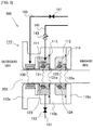
- FIG. 1 is a view showing the schematic construction of the stern tube sealing device according to this embodiment.
- Fig. 2 is a schematic cross sectional view of seal rings formed in the stern tube sealing device according to this embodiment.
- a left side is an outboard side (stern side)
- a right side is an inboard side (bow side).
- the stern tube sealing device according to this embodiment is for a marine vessel used in seas.
- water outside the marine vessel i.e., outboard water
- the stern tube sealing device according to the present invention can also be applied to a stern tube sealing device for a marine vessel used in rivers, etc.
- a propeller shaft 200 is inserted through a seal housing 110.
- the propeller shaft 200 is equipped, an outboard side tip end portion thereof, with a propeller (not shown).
- the seal housing 110 is composed of a seal case 110a, a first mating ring 110b and a second mating ring 110c, which are fastened to one another by means of bolts or the like.
- An O ring 113 is interposed between the seal case 110a and the first mating ring 110b, so that these seal case and mating ring are sealed by means of the O ring 113.
- an O ring 114 is interposed between the first mating ring 110b and the second mating ring 110c, so that these first and second mating rings are sealed by means of the O ring 114.
- the seal case 110a, the first mating ring 110b and the second mating ring 110c have their inner peripheral surfaces arranged in positions which are separated by a predetermined gap with respect to an outer peripheral surface of the propeller shaft 200.
- the predetermined gap is provided between the inner peripheral surface of the seal housing 110 and the outer peripheral surface of the propeller shaft 200.
- the seal case 110a is formed on its inner peripheral surface at the side of the first mating ring 110b with an annular concave portion along the outer peripheral surface of the propeller shaft 200.
- a first seal ring chamber 111 is formed by an annular space which is surrounded by a wall surface of the concave portion of this seal case 110a and a wall surface of the first mating ring 110b at the side of the seal case 110a.
- first mating ring 110b is also formed on its inner peripheral surface at the side of the second mating ring 110c with an annular concave portion along the outer peripheral surface of the propeller shaft 200.
- a second seal ring chamber 112 is formed by an annular space which is surrounded by a wall surface of the concave portion of this first mating ring 110b and a wall surface of the second mating ring 110c at the side of the first mating ring 110b. That is, in the seal housing 110, the second seal ring chamber 112 is located at an inboard side of the first seal ring chamber 111.
- a first seal ring 121 is arranged in the first seal ring chamber 111.
- a second seal ring 122 is arranged in the second seal ring chamber 112.
- the first seal ring 121 and the second seal ring 122 are fixedly secured to the propeller shaft 200 by means of garter springs 123, 124, respectively, so that they rotate together with the propeller shaft 200.
- the individual seal rings 121, 122 have lip portions 121b, 122b, respectively.
- the lip portion 121b of the first seal ring 121 is in contact with an inboard side wall surface of the first seal ring chamber 111 (i.e., a wall surface of the first mating ring 110b at the side of the seal case 110a).
- a surface in this lip portion 121b in contact with the wall surface of the first seal ring chamber 111 is a sealing surface 121a which slides with respect to the wall surface of the first seal ring chamber 111.
- the lip portion 122b of the second seal ring 122 is in contact with an inboard side wall surface of the second seal ring chamber 112 (i.e., a wall surface of the second mating ring 110c at the side of the first mating ring 110b).
- a surface in this lip portion 122b in contact with the wall surface of the second seal ring chamber 112 is a sealing surface 121a which slides with respect to the wall surface of the second seal ring chamber 112.
- the predetermined gap or interval is provided between the inner peripheral surface of the seal housing 110 and the outer peripheral surface of the propeller shaft 200.
- the first seal ring chamber 111 is in communication with the outside of the marine vessel.
- the first seal ring chamber 111 and the second seal ring chamber 112 are in communication with each other through the sliding portions between the sealing surface 121a of the first seal ring 121 and the wall surface of the first seal ring chamber 111.
- sealing is exhibited by maintaining a state in which at least either one of the sealing surfaces 121a, 122a of the first seal ring 121 and the second seal ring 122 is in intimate contact with the wall surface of the first seal ring chamber 111 or the second seal ring chamber 112.
- Another concave portion is formed at a more outboard side than the concave portion in the inner peripheral surface of the seal case 110a which forms the first seal ring chamber 111.
- An inflatable seal 130 is arranged in this concave portion.
- An air introduction pipe 160 is connected to the inflatable seal 130.
- a valve 161 is arranged in the air introduction pipe 160.
- a sea water introduction pipe 141 is connected to the first seal ring chamber 111, and a clear water introduction pipe 142 is connected to the second seal ring chamber 112.
- the sea water SW pumped up from outboard sea is introduced through the sea water introduction pipe 141.
- a flow rate regulation valve 143 is arranged in the sea water introduction pipe 141.
- the flow rate of the sea water SW to be introduced into the first seal ring chamber 111 is regulated by this flow rate regulation valve 143.
- the pressure of the sea water in the first seal ring chamber 111 can be regulated.
- a drain pipe 151 is connected to the first seal ring chamber 111.
- a drain valve 153 is arranged in the drain pipe 151. By opening this drain valve 153, the sea water SW can be caused to discharge from the interior of the first seal ring chamber 111 through the drain pipe 151
- An end of the clear water introduction pipe 142 opposite to its end connected to the second seal ring chamber 112 is connected to a clear water tank 145 in which clear water W equipped by the marine vessel is stored. Then, the clear water W stored in the clear water tank 145 is introduced into the second seal ring chamber 112 through the clear water introduction pipe 142.
- a flow rate regulation valve 144 is arranged in the clear water introduction pipe 142. The flow rate of the clear water W to be introduced into the second seal ring chamber 112 is regulated by this flow rate regulation valve 144. By regulating the flow rate of the clear water W to be introduced into the second seal ring chamber 112, the pressure of the clear water in the second seal ring chamber 112 can be regulated.
- clear water may be directly supplied to the second seal chamber through a flow rate regulation valve from this clear water supply line.
- a drain pipe 152 is connected to the second seal ring chamber 112.
- a drain valve 154 is arranged in the drain pipe 152. By opening this drain valve 154, the clear water W can be caused to discharge from the interior of the second seal ring chamber 112 through the drain pipe 152.
- the sea water SW is introduced into the first seal ring chamber 111, and the clear water W is introduced into the second seal ring chamber 112.
- the individual seal rings 121, 122 can be cooled with the sea water SW or the clear water W filled in each of the seal ring chambers 111, 112.
- the clear water with no slurry mixed therein is filled in the second seal ring chamber 112.
- the clear water with no slurry mixed therein is filled in the second seal ring chamber 112.
- the first seal ring chamber 111 and the second seal ring chamber 112 are in communication with each other through the sliding portions between the sealing surface 121a of the first seal ring 121 and the wall surface of the first seal ring chamber 111.
- the above-mentioned state in which communication is made through the sliding portions is said to be a state in which the sealing surface 121a and the wall surface of the first seal ring chamber 111 are in contact with each other in such a manner that the sea water SW or the clear water W, which is a target for hermetic seal, is permitted to permeate into between the sealing surface 121a and the wall surface of the first seal ring chamber 111, within a range in which the sealing by the sliding portions is not affected.
- the construction is such that a certain amount of leakage of the fluid to be sealed to the sliding portions is permitted, so that the fluid to be sealed is made to interpose between the sealing surface 121a and the wall surface of the first seal ring chamber 111, thereby enhancing lubrication in the sliding portions.
- it is constructed such that the clear water filled in the second seal ring chamber 112 comes into the sliding portions between the wall surface of the first seal ring chamber 111 and the sealing surface 121a of the first seal ring 121.
- the slurry is suppressed from depositing on the sliding portions between the wall surface of each of the seal ring chambers 111, 112 and the sealing surfaces 121a, 122a of the first seal ring 121, it is possible to suppress reduction in sealing due to the slurry.
- the pressure of the clear water in the second seal ring chamber 112 may also be made higher than the pressure of the sea water in the first seal ring chamber 111.
- the hydrostatic pressure in the second seal ring chamber 112 can be made higher by making the installation position of the clear water tank 145 in the marine vessel higher with respect to a waterline thereof.
- the pressure of the clear water in the second seal ring chamber 112 may also be made lower than the pressure of the sea water in the first seal ring chamber 111.
- the sealing surface 121a of the first seal ring 121 is more strongly pushed against the wall surface of the first seal ring chamber 111 by means of the pressure of the sea water in the first seal ring chamber 111. Accordingly, an amount of float or lift of the lip portion 121b of the first seal ring 121 from the wall surface of the first seal ring chamber 111 becomes small. For that reason, it becomes more difficult for the slurry, which is contained in the sea water SW filled in the first seal ring chamber 111, to come into the sliding portions between the wall surface of the first seal ring chamber 111 and the sealing surface 121a of the first seal ring 121. Accordingly, it becomes possible to suppress the slurry from depositing on these sliding portions in a more effective manner.
- FIG. 3 is a view showing the schematic construction of the stern tube sealing device according to this modification.
- the stern tube sealing device 300 according to this modification is different from the stern tube sealing device 100 according to the above-mentioned embodiment in that the clear water W is sealed in the second seal ring chamber 112.
- the pressure of the clear water in the second seal ring chamber 112 is lower than the pressure of the sea water in the first seal ring chamber 111.
- this modification it becomes unnecessary to provide a device for introducing the clear water W into the second seal ring chamber 112 (i.e., the clear water introduction pipe 142, the flow control valve 144, and the clear water tank 145 in Fig. 1 ) and a device for causing the clear water W to discharge from the interior of the second seal ring chamber 112 (i.e., the drain pipe 152 and the drain valve 154 in Fig. 1 ).
- a device for introducing the clear water W into the second seal ring chamber 112 i.e., the clear water introduction pipe 142, the flow control valve 144, and the clear water tank 145 in Fig. 1
- a device for causing the clear water W to discharge from the interior of the second seal ring chamber 112 i.e., the drain pipe 152 and the drain valve 154 in Fig. 1 .
- the structure of the stern tube sealing device 300 can be further simplified.
- the above-mentioned stern tube sealing devices 100, 300 are constructed in such a manner that the individual seal rings 121, 122 are fixedly secured to the propeller shaft 200 so as to permit the sealing surfaces 121a, 122a thereof to slide with respect to the wall surfaces of the individual seal ring chambers 111, 112.
- the present invention can also be applied to a stern tube sealing device of a construction in which each seal ring is fixedly secured to a seal housing side in each seal ring chamber, with its sealing surface being slidable with respect to an outer peripheral surface of a propeller shaft.
- sea water may be filled into an outboard side seal ring chamber, and clear water may be filled into an inboard side seal ring chamber. According to this, it becomes difficult for slurry contained in sea water to come into sliding portions between the outer peripheral surface of the propeller shaft and the sealing surface of each seal ring. As a result, it becomes possible to suppress the slurry from depositing on these sliding portions in a more effective manner.
- the pressure in the clear water in the inboard side seal ring chamber may also be made higher than the pressure of the sea water in the outboard side seal ring chamber, similar to the case of the above-mentioned embodiments. According to this, similar effects can be obtained, as in the case of [First Example of the Water Pressures in the Seal Ring Chambers] in the above-mentioned embodiment. Moreover, the pressure of the clear water in the inboard side seal ring chamber may also be made lower than the pressure of the sea water in the outboard side seal ring chamber. According to this, similar effects can be obtained, as in the case of [Second Example of the Water Pressures in the Seal Ring Chambers] in the above-mentioned embodiment.
Landscapes
- Engineering & Computer Science (AREA)
- General Engineering & Computer Science (AREA)
- Mechanical Engineering (AREA)
- Chemical & Material Sciences (AREA)
- Combustion & Propulsion (AREA)
- Ocean & Marine Engineering (AREA)
- Physics & Mathematics (AREA)
- Fluid Mechanics (AREA)
- Sealing Devices (AREA)
- Sealing With Elastic Sealing Lips (AREA)
Claims (2)
- Stevenrohrdichtvorrichtung (100; 300), die angepasst ist, um einen Außenumfang einer Propellerwelle (200) in einem Seefahrzeug abzudichten, wobei die Stevenrohrdichtvorrichtung (100; 300) folgendes aufweist:ein Dichtgehäuse (110), durch das die Propellerwelle (200) eingesetzt ist;einen ersten Dichtring (121), der in einer ersten Dichtringkammer (111) angeordnet ist, die in dem Dichtgehäuse (110) ausgebildet ist, und eine Dichtfläche hat, die hinsichtlich einer Wandfläche der ersten Dichtringkammer (111) oder einer Außenumfangsfläche der Propellerwelle (200) gleitet; undeinen zweiten Dichtring (122), der in einer zweiten Dichtringkammer (112) angeordnet ist, die in dem Dichtgehäuse (110) auf einer Innenbordseite des ersten Dichtrings (111) ausgebildet ist, und eine Dichtfläche hat, die hinsichtlich einer Wandfläche der zweiten Dichtringkammer (112) oder der Außenumfangsfläche der Propellerwelle (200) gleitet;wobei die erste Dichtringkammer (111) in Verbindung mit einer Außenseite des Seefahrzeugs ist, unddie erste Dichtringkammer (111) und die zweite Dichtringkammer (112) miteinander durch Gleitabschnitte zwischen der Wandfläche der ersten Dichtringkammer (111) oder der Außenumfangsfläche der Propellerwelle (200) und der Dichtfläche des ersten Dichtrings (121) in Verbindung stehen;wobei Außenbordwasser in die erste Dichtringkammer (111) gefüllt ist;dadurch gekennzeichnet, dassklares Wasser (W) abgedichtet in der zweiten Dichtringkammer (112) eingeschlossen ist; undder Druck des klaren Wassers (W) in der zweiten Dichtringkammer (112) geringer als der Druck des Wassers in der ersten Dichtringkammer (111) ist.
- Stevenrohrdichtvorrichtung (100; 300) nach Anspruch 1, ferner mit einer Seewassereinleitungsleitung (141), die mit der ersten Dichtringkammer (111) verbunden ist, und einem Strömungsratenregulierventil (143) in der Seewassereinleitungsleitung (141).
Applications Claiming Priority (2)
| Application Number | Priority Date | Filing Date | Title |
|---|---|---|---|
| JP2012167520 | 2012-07-27 | ||
| PCT/JP2013/068653 WO2014017285A1 (ja) | 2012-07-27 | 2013-07-08 | 船尾管シール装置 |
Publications (3)
| Publication Number | Publication Date |
|---|---|
| EP2878865A1 EP2878865A1 (de) | 2015-06-03 |
| EP2878865A4 EP2878865A4 (de) | 2016-03-09 |
| EP2878865B1 true EP2878865B1 (de) | 2018-03-21 |
Family
ID=49997101
Family Applications (1)
| Application Number | Title | Priority Date | Filing Date |
|---|---|---|---|
| EP13822252.6A Active EP2878865B1 (de) | 2012-07-27 | 2013-07-08 | Dichtungsvorrichtung für ein heckrohr |
Country Status (5)
| Country | Link |
|---|---|
| US (1) | US9868502B2 (de) |
| EP (1) | EP2878865B1 (de) |
| JP (1) | JP6199290B2 (de) |
| CN (1) | CN104067037B (de) |
| WO (1) | WO2014017285A1 (de) |
Families Citing this family (4)
| Publication number | Priority date | Publication date | Assignee | Title |
|---|---|---|---|---|
| CN106628092A (zh) * | 2017-03-07 | 2017-05-10 | 合肥倍豪海洋装备技术有限公司 | 一种全回转式舵桨用密封系统 |
| CN112594099B (zh) * | 2020-11-26 | 2022-10-28 | 中国船舶重工集团公司第七0五研究所 | 一种多航态航行器进气管 |
| JP7777124B2 (ja) * | 2021-04-08 | 2025-11-27 | イーグルブルグマンジャパン株式会社 | 軸封装置 |
| CN116873183B (zh) * | 2023-07-13 | 2026-01-27 | 武汉理工大学 | 一种适用于内河泥沙水域的船舶艉轴闭式水润滑系统 |
Family Cites Families (23)
| Publication number | Priority date | Publication date | Assignee | Title |
|---|---|---|---|---|
| US2946608A (en) * | 1955-10-27 | 1960-07-26 | Syntron Co | Continuously washed shaft seal |
| US3625523A (en) * | 1970-02-13 | 1971-12-07 | Waukesha Bearings Corp | Aft sealing assembly for stern tubes |
| BE790095A (fr) * | 1971-10-20 | 1973-04-13 | Mobil Oil Corp | Dispositif de support a joint d'etancheite d'arbre d'helice d'un navir |
| JPS52115096A (en) | 1976-03-23 | 1977-09-27 | Nippon Kokan Kk <Nkk> | Device for recovering leaked oil at stern tubular bearing oil sealing portion |
| NL191701C (nl) * | 1981-04-13 | 1996-04-02 | Blohm Voss Ag | Afdichtstelsel voor een lekveilige afdichting van een schroefaskoker. |
| DE3122406A1 (de) | 1981-06-05 | 1982-12-23 | Howaldtswerke-Deutsche Werft Ag Hamburg Und Kiel, 2300 Kiel | Abdichtungsanordnung, insbesondere fuer hintere stevenrohrabdichtungen |
| JPS59165300U (ja) * | 1983-04-21 | 1984-11-06 | 三菱重工業株式会社 | 船尾管軸封装置 |
| DE3718411A1 (de) * | 1987-06-02 | 1988-12-15 | Blohm Voss Ag | Sicherheitseinrichtung an einer abdichtungsanordnung fuer rotierende wellen, insbesondere fuer stevenrohre von schiffsantrieben |
| JPH0535249Y2 (de) * | 1988-03-31 | 1993-09-07 | ||
| JPH066194A (ja) | 1992-06-19 | 1994-01-14 | Sanyo Electric Co Ltd | 電子機器の誤動作防止回路 |
| JP3117332B2 (ja) | 1993-06-25 | 2000-12-11 | 三菱重工業株式会社 | 船尾管軸封装置 |
| DE4434247B4 (de) * | 1994-09-24 | 2004-07-15 | B + V Industrietechnik Gmbh | Sicherheitsvorrichtung an Abdichtungsanordnungen für Propellerwellen von Schiffen |
| JPH0972427A (ja) * | 1995-09-04 | 1997-03-18 | Nippon Marine Techno Kk | 船尾管シール装置 |
| JP3155461B2 (ja) * | 1996-04-09 | 2001-04-09 | 株式会社コベルコ・マリンエンジニアリング | 船尾管シール装置の圧力調整法 |
| JP4109374B2 (ja) | 1999-02-23 | 2008-07-02 | バルチラジャパン株式会社 | 船尾管シール装置 |
| JP2001066757A (ja) * | 2000-08-07 | 2001-03-16 | Seiko Epson Corp | 露光方法 |
| DE10040211C2 (de) * | 2000-08-17 | 2002-10-17 | B & V Industrietechnik Gmbh | Vorrichtung zur Abdichtung von Antriebswellen |
| JP2002340199A (ja) * | 2001-05-11 | 2002-11-27 | Eagle Ind Co Ltd | 船尾管軸封装置 |
| NL1023796C2 (nl) * | 2003-07-02 | 2005-01-04 | Ihc Holland Nv | Afdichtstelsel voor het afdichten van een schroefaskoker met een daardoor heen lopende schroefas. |
| JP4577822B2 (ja) * | 2004-10-01 | 2010-11-10 | Kemel株式会社 | 船尾管軸受用軸封装置 |
| JP2010006105A (ja) * | 2008-06-24 | 2010-01-14 | Faltec Co Ltd | 検出装置の取付装置及び車両構成体 |
| JP5195187B2 (ja) | 2008-09-05 | 2013-05-08 | イーグルブルグマンジャパン株式会社 | 船尾管軸封装置 |
| CN101788055A (zh) * | 2009-01-22 | 2010-07-28 | 江苏华阳重工科技股份有限公司 | 船舶高耐压油润滑密封装置 |
-
2013
- 2013-07-08 JP JP2014526844A patent/JP6199290B2/ja active Active
- 2013-07-08 WO PCT/JP2013/068653 patent/WO2014017285A1/ja not_active Ceased
- 2013-07-08 US US14/375,563 patent/US9868502B2/en active Active
- 2013-07-08 CN CN201380006538.7A patent/CN104067037B/zh active Active
- 2013-07-08 EP EP13822252.6A patent/EP2878865B1/de active Active
Non-Patent Citations (1)
| Title |
|---|
| None * |
Also Published As
| Publication number | Publication date |
|---|---|
| EP2878865A4 (de) | 2016-03-09 |
| WO2014017285A1 (ja) | 2014-01-30 |
| US20150137458A1 (en) | 2015-05-21 |
| JPWO2014017285A1 (ja) | 2016-07-07 |
| CN104067037B (zh) | 2016-10-26 |
| EP2878865A1 (de) | 2015-06-03 |
| JP6199290B2 (ja) | 2017-09-20 |
| US9868502B2 (en) | 2018-01-16 |
| CN104067037A (zh) | 2014-09-24 |
Similar Documents
| Publication | Publication Date | Title |
|---|---|---|
| AU608393B2 (en) | An assembly for sealing the propeller shaft of a ship | |
| CN104321250B (zh) | 用于密封船舶的推进器轴的装置以及控制其操作的方法 | |
| US9868502B2 (en) | Stern tube sealing device | |
| KR101899337B1 (ko) | 선박을 위한 밀봉 장치, 추진 장치, 선박, 및 선박의 프로펠러 샤프트를 밀봉하기 위한 방법 | |
| CN109681533B (zh) | 一种封闭式水润滑轴承系统 | |
| JPH0210000B2 (de) | ||
| EP2452871A1 (de) | Dichtungsvorrichtung und verfahren für den ersatz einer dichtung für die antriebswelle eines seefahrzeuges | |
| JP4755428B2 (ja) | 船舶用推進軸の軸封装置 | |
| US20130313786A1 (en) | Sealing Ring | |
| KR101151640B1 (ko) | 선미관 시일 장치의 압력 조절 장치 | |
| US8567792B2 (en) | Gas seal structure | |
| KR20020086236A (ko) | 선미관축 밀봉장치 | |
| EP3971432B1 (de) | Verwendung einer dichtungsvorrichtung | |
| JP3668709B2 (ja) | ポッドプロペラ推進システムのシール装置 | |
| CN212318359U (zh) | 一种挖泥船泥泵封水水质净化处理结构装置 | |
| JPH07242197A (ja) | 船尾管シール装置 | |
| JPH07242198A (ja) | 船尾管シール装置 | |
| CN101769380B (zh) | 自调压型船舶油润滑密封装置 | |
| CN101788056A (zh) | 油压自调整船舶油润滑密封装置 | |
| JP2005041348A (ja) | 船舶用推進軸の軸封装置及び軸封方法 | |
| CN210397718U (zh) | 一种极地航行船舶的尾轴密封系统 | |
| JPH0645439Y2 (ja) | 船尾管シール装置 | |
| JPH079760Y2 (ja) | 船尾管軸封装置 | |
| WO2019202490A1 (en) | Emergency seal | |
| KR101158608B1 (ko) | 선미관 시일 장치의 압력 제어 장치 |
Legal Events
| Date | Code | Title | Description |
|---|---|---|---|
| PUAI | Public reference made under article 153(3) epc to a published international application that has entered the european phase |
Free format text: ORIGINAL CODE: 0009012 |
|
| 17P | Request for examination filed |
Effective date: 20140730 |
|
| AK | Designated contracting states |
Kind code of ref document: A1 Designated state(s): AL AT BE BG CH CY CZ DE DK EE ES FI FR GB GR HR HU IE IS IT LI LT LU LV MC MK MT NL NO PL PT RO RS SE SI SK SM TR |
|
| AX | Request for extension of the european patent |
Extension state: BA ME |
|
| DAX | Request for extension of the european patent (deleted) | ||
| RA4 | Supplementary search report drawn up and despatched (corrected) |
Effective date: 20160208 |
|
| RIC1 | Information provided on ipc code assigned before grant |
Ipc: B63H 23/32 20060101ALI20160202BHEP Ipc: F16J 15/324 20160101ALI20160202BHEP Ipc: F16J 15/40 20060101ALI20160202BHEP Ipc: F16J 15/00 20060101ALI20160202BHEP Ipc: F16J 15/34 20060101ALI20160202BHEP Ipc: B63H 23/36 20060101ALI20160202BHEP Ipc: F16J 15/32 20060101ALI20160202BHEP Ipc: F16J 15/48 20060101AFI20160202BHEP |
|
| STAA | Information on the status of an ep patent application or granted ep patent |
Free format text: STATUS: EXAMINATION IS IN PROGRESS |
|
| 17Q | First examination report despatched |
Effective date: 20170207 |
|
| GRAP | Despatch of communication of intention to grant a patent |
Free format text: ORIGINAL CODE: EPIDOSNIGR1 |
|
| STAA | Information on the status of an ep patent application or granted ep patent |
Free format text: STATUS: GRANT OF PATENT IS INTENDED |
|
| INTG | Intention to grant announced |
Effective date: 20171122 |
|
| GRAS | Grant fee paid |
Free format text: ORIGINAL CODE: EPIDOSNIGR3 |
|
| GRAA | (expected) grant |
Free format text: ORIGINAL CODE: 0009210 |
|
| STAA | Information on the status of an ep patent application or granted ep patent |
Free format text: STATUS: THE PATENT HAS BEEN GRANTED |
|
| AK | Designated contracting states |
Kind code of ref document: B1 Designated state(s): AL AT BE BG CH CY CZ DE DK EE ES FI FR GB GR HR HU IE IS IT LI LT LU LV MC MK MT NL NO PL PT RO RS SE SI SK SM TR |
|
| REG | Reference to a national code |
Ref country code: GB Ref legal event code: FG4D |
|
| REG | Reference to a national code |
Ref country code: CH Ref legal event code: EP |
|
| REG | Reference to a national code |
Ref country code: AT Ref legal event code: REF Ref document number: 981463 Country of ref document: AT Kind code of ref document: T Effective date: 20180415 |
|
| REG | Reference to a national code |
Ref country code: IE Ref legal event code: FG4D |
|
| REG | Reference to a national code |
Ref country code: DE Ref legal event code: R096 Ref document number: 602013034821 Country of ref document: DE |
|
| REG | Reference to a national code |
Ref country code: NL Ref legal event code: MP Effective date: 20180321 |
|
| PG25 | Lapsed in a contracting state [announced via postgrant information from national office to epo] |
Ref country code: HR Free format text: LAPSE BECAUSE OF FAILURE TO SUBMIT A TRANSLATION OF THE DESCRIPTION OR TO PAY THE FEE WITHIN THE PRESCRIBED TIME-LIMIT Effective date: 20180321 Ref country code: NO Free format text: LAPSE BECAUSE OF FAILURE TO SUBMIT A TRANSLATION OF THE DESCRIPTION OR TO PAY THE FEE WITHIN THE PRESCRIBED TIME-LIMIT Effective date: 20180621 Ref country code: FI Free format text: LAPSE BECAUSE OF FAILURE TO SUBMIT A TRANSLATION OF THE DESCRIPTION OR TO PAY THE FEE WITHIN THE PRESCRIBED TIME-LIMIT Effective date: 20180321 Ref country code: LT Free format text: LAPSE BECAUSE OF FAILURE TO SUBMIT A TRANSLATION OF THE DESCRIPTION OR TO PAY THE FEE WITHIN THE PRESCRIBED TIME-LIMIT Effective date: 20180321 Ref country code: CY Free format text: LAPSE BECAUSE OF FAILURE TO SUBMIT A TRANSLATION OF THE DESCRIPTION OR TO PAY THE FEE WITHIN THE PRESCRIBED TIME-LIMIT Effective date: 20180321 |
|
| REG | Reference to a national code |
Ref country code: LT Ref legal event code: MG4D |
|
| REG | Reference to a national code |
Ref country code: AT Ref legal event code: MK05 Ref document number: 981463 Country of ref document: AT Kind code of ref document: T Effective date: 20180321 |
|
| PG25 | Lapsed in a contracting state [announced via postgrant information from national office to epo] |
Ref country code: GR Free format text: LAPSE BECAUSE OF FAILURE TO SUBMIT A TRANSLATION OF THE DESCRIPTION OR TO PAY THE FEE WITHIN THE PRESCRIBED TIME-LIMIT Effective date: 20180622 Ref country code: SE Free format text: LAPSE BECAUSE OF FAILURE TO SUBMIT A TRANSLATION OF THE DESCRIPTION OR TO PAY THE FEE WITHIN THE PRESCRIBED TIME-LIMIT Effective date: 20180321 Ref country code: LV Free format text: LAPSE BECAUSE OF FAILURE TO SUBMIT A TRANSLATION OF THE DESCRIPTION OR TO PAY THE FEE WITHIN THE PRESCRIBED TIME-LIMIT Effective date: 20180321 Ref country code: BG Free format text: LAPSE BECAUSE OF FAILURE TO SUBMIT A TRANSLATION OF THE DESCRIPTION OR TO PAY THE FEE WITHIN THE PRESCRIBED TIME-LIMIT Effective date: 20180621 Ref country code: RS Free format text: LAPSE BECAUSE OF FAILURE TO SUBMIT A TRANSLATION OF THE DESCRIPTION OR TO PAY THE FEE WITHIN THE PRESCRIBED TIME-LIMIT Effective date: 20180321 |
|
| PG25 | Lapsed in a contracting state [announced via postgrant information from national office to epo] |
Ref country code: IT Free format text: LAPSE BECAUSE OF FAILURE TO SUBMIT A TRANSLATION OF THE DESCRIPTION OR TO PAY THE FEE WITHIN THE PRESCRIBED TIME-LIMIT Effective date: 20180321 Ref country code: RO Free format text: LAPSE BECAUSE OF FAILURE TO SUBMIT A TRANSLATION OF THE DESCRIPTION OR TO PAY THE FEE WITHIN THE PRESCRIBED TIME-LIMIT Effective date: 20180321 Ref country code: AL Free format text: LAPSE BECAUSE OF FAILURE TO SUBMIT A TRANSLATION OF THE DESCRIPTION OR TO PAY THE FEE WITHIN THE PRESCRIBED TIME-LIMIT Effective date: 20180321 Ref country code: EE Free format text: LAPSE BECAUSE OF FAILURE TO SUBMIT A TRANSLATION OF THE DESCRIPTION OR TO PAY THE FEE WITHIN THE PRESCRIBED TIME-LIMIT Effective date: 20180321 Ref country code: NL Free format text: LAPSE BECAUSE OF FAILURE TO SUBMIT A TRANSLATION OF THE DESCRIPTION OR TO PAY THE FEE WITHIN THE PRESCRIBED TIME-LIMIT Effective date: 20180321 Ref country code: PL Free format text: LAPSE BECAUSE OF FAILURE TO SUBMIT A TRANSLATION OF THE DESCRIPTION OR TO PAY THE FEE WITHIN THE PRESCRIBED TIME-LIMIT Effective date: 20180321 Ref country code: ES Free format text: LAPSE BECAUSE OF FAILURE TO SUBMIT A TRANSLATION OF THE DESCRIPTION OR TO PAY THE FEE WITHIN THE PRESCRIBED TIME-LIMIT Effective date: 20180321 |
|
| PG25 | Lapsed in a contracting state [announced via postgrant information from national office to epo] |
Ref country code: AT Free format text: LAPSE BECAUSE OF FAILURE TO SUBMIT A TRANSLATION OF THE DESCRIPTION OR TO PAY THE FEE WITHIN THE PRESCRIBED TIME-LIMIT Effective date: 20180321 Ref country code: CZ Free format text: LAPSE BECAUSE OF FAILURE TO SUBMIT A TRANSLATION OF THE DESCRIPTION OR TO PAY THE FEE WITHIN THE PRESCRIBED TIME-LIMIT Effective date: 20180321 Ref country code: SK Free format text: LAPSE BECAUSE OF FAILURE TO SUBMIT A TRANSLATION OF THE DESCRIPTION OR TO PAY THE FEE WITHIN THE PRESCRIBED TIME-LIMIT Effective date: 20180321 Ref country code: SM Free format text: LAPSE BECAUSE OF FAILURE TO SUBMIT A TRANSLATION OF THE DESCRIPTION OR TO PAY THE FEE WITHIN THE PRESCRIBED TIME-LIMIT Effective date: 20180321 |
|
| PG25 | Lapsed in a contracting state [announced via postgrant information from national office to epo] |
Ref country code: PT Free format text: LAPSE BECAUSE OF FAILURE TO SUBMIT A TRANSLATION OF THE DESCRIPTION OR TO PAY THE FEE WITHIN THE PRESCRIBED TIME-LIMIT Effective date: 20180723 |
|
| REG | Reference to a national code |
Ref country code: DE Ref legal event code: R097 Ref document number: 602013034821 Country of ref document: DE |
|
| PLBE | No opposition filed within time limit |
Free format text: ORIGINAL CODE: 0009261 |
|
| STAA | Information on the status of an ep patent application or granted ep patent |
Free format text: STATUS: NO OPPOSITION FILED WITHIN TIME LIMIT |
|
| PG25 | Lapsed in a contracting state [announced via postgrant information from national office to epo] |
Ref country code: DK Free format text: LAPSE BECAUSE OF FAILURE TO SUBMIT A TRANSLATION OF THE DESCRIPTION OR TO PAY THE FEE WITHIN THE PRESCRIBED TIME-LIMIT Effective date: 20180321 |
|
| 26N | No opposition filed |
Effective date: 20190102 |
|
| REG | Reference to a national code |
Ref country code: CH Ref legal event code: PL |
|
| GBPC | Gb: european patent ceased through non-payment of renewal fee |
Effective date: 20180708 |
|
| PG25 | Lapsed in a contracting state [announced via postgrant information from national office to epo] |
Ref country code: MC Free format text: LAPSE BECAUSE OF FAILURE TO SUBMIT A TRANSLATION OF THE DESCRIPTION OR TO PAY THE FEE WITHIN THE PRESCRIBED TIME-LIMIT Effective date: 20180321 Ref country code: LU Free format text: LAPSE BECAUSE OF NON-PAYMENT OF DUE FEES Effective date: 20180708 |
|
| REG | Reference to a national code |
Ref country code: BE Ref legal event code: MM Effective date: 20180731 |
|
| REG | Reference to a national code |
Ref country code: IE Ref legal event code: MM4A |
|
| PG25 | Lapsed in a contracting state [announced via postgrant information from national office to epo] |
Ref country code: FR Free format text: LAPSE BECAUSE OF NON-PAYMENT OF DUE FEES Effective date: 20180731 Ref country code: CH Free format text: LAPSE BECAUSE OF NON-PAYMENT OF DUE FEES Effective date: 20180731 Ref country code: LI Free format text: LAPSE BECAUSE OF NON-PAYMENT OF DUE FEES Effective date: 20180731 Ref country code: IE Free format text: LAPSE BECAUSE OF NON-PAYMENT OF DUE FEES Effective date: 20180708 Ref country code: GB Free format text: LAPSE BECAUSE OF NON-PAYMENT OF DUE FEES Effective date: 20180708 |
|
| PG25 | Lapsed in a contracting state [announced via postgrant information from national office to epo] |
Ref country code: SI Free format text: LAPSE BECAUSE OF FAILURE TO SUBMIT A TRANSLATION OF THE DESCRIPTION OR TO PAY THE FEE WITHIN THE PRESCRIBED TIME-LIMIT Effective date: 20180321 Ref country code: BE Free format text: LAPSE BECAUSE OF NON-PAYMENT OF DUE FEES Effective date: 20180731 |
|
| PG25 | Lapsed in a contracting state [announced via postgrant information from national office to epo] |
Ref country code: MT Free format text: LAPSE BECAUSE OF NON-PAYMENT OF DUE FEES Effective date: 20180708 |
|
| PG25 | Lapsed in a contracting state [announced via postgrant information from national office to epo] |
Ref country code: TR Free format text: LAPSE BECAUSE OF FAILURE TO SUBMIT A TRANSLATION OF THE DESCRIPTION OR TO PAY THE FEE WITHIN THE PRESCRIBED TIME-LIMIT Effective date: 20180321 |
|
| PG25 | Lapsed in a contracting state [announced via postgrant information from national office to epo] |
Ref country code: HU Free format text: LAPSE BECAUSE OF FAILURE TO SUBMIT A TRANSLATION OF THE DESCRIPTION OR TO PAY THE FEE WITHIN THE PRESCRIBED TIME-LIMIT; INVALID AB INITIO Effective date: 20130708 |
|
| PG25 | Lapsed in a contracting state [announced via postgrant information from national office to epo] |
Ref country code: MK Free format text: LAPSE BECAUSE OF NON-PAYMENT OF DUE FEES Effective date: 20180321 |
|
| PG25 | Lapsed in a contracting state [announced via postgrant information from national office to epo] |
Ref country code: IS Free format text: LAPSE BECAUSE OF FAILURE TO SUBMIT A TRANSLATION OF THE DESCRIPTION OR TO PAY THE FEE WITHIN THE PRESCRIBED TIME-LIMIT Effective date: 20180721 |
|
| PGFP | Annual fee paid to national office [announced via postgrant information from national office to epo] |
Ref country code: DE Payment date: 20250528 Year of fee payment: 13 |