EP2906661B1 - Materialien für organische elektrolumineszenzvorrichtungen - Google Patents
Materialien für organische elektrolumineszenzvorrichtungen Download PDFInfo
- Publication number
- EP2906661B1 EP2906661B1 EP13762409.4A EP13762409A EP2906661B1 EP 2906661 B1 EP2906661 B1 EP 2906661B1 EP 13762409 A EP13762409 A EP 13762409A EP 2906661 B1 EP2906661 B1 EP 2906661B1
- Authority
- EP
- European Patent Office
- Prior art keywords
- group
- aromatic
- atoms
- organic
- compound according
- Prior art date
- Legal status (The legal status is an assumption and is not a legal conclusion. Google has not performed a legal analysis and makes no representation as to the accuracy of the status listed.)
- Active
Links
- 0 CC1=C(C)****1 Chemical compound CC1=C(C)****1 0.000 description 15
- PCZAIQYILJYEGO-UHFFFAOYSA-N O=C(c(cccc1)c1-c1cc(Br)cc(-c2c3cccc2)c11)N1C3=O Chemical compound O=C(c(cccc1)c1-c1cc(Br)cc(-c2c3cccc2)c11)N1C3=O PCZAIQYILJYEGO-UHFFFAOYSA-N 0.000 description 3
- OVKVRJXIDMFTFT-UHFFFAOYSA-N N#Cc(cccc1)c1-c(cc1-c(cc(cc2-c3c4cccc3)Br)c2N2C4=O)ccc1C2=O Chemical compound N#Cc(cccc1)c1-c(cc1-c(cc(cc2-c3c4cccc3)Br)c2N2C4=O)ccc1C2=O OVKVRJXIDMFTFT-UHFFFAOYSA-N 0.000 description 2
- FLLOOAPWQQAZII-UHFFFAOYSA-N BrCc(c(Br)ccc1)c1-c1ccccc1 Chemical compound BrCc(c(Br)ccc1)c1-c1ccccc1 FLLOOAPWQQAZII-UHFFFAOYSA-N 0.000 description 1
- BIBQPUKGBSKQKY-UHFFFAOYSA-N C(c1c-2cccc1)Nc1c-2[s]cc1 Chemical compound C(c1c-2cccc1)Nc1c-2[s]cc1 BIBQPUKGBSKQKY-UHFFFAOYSA-N 0.000 description 1
- HMYXAROFHNIECU-UHFFFAOYSA-N C1Nc2ccccc2-c2nc(nccc3)c3cc12 Chemical compound C1Nc2ccccc2-c2nc(nccc3)c3cc12 HMYXAROFHNIECU-UHFFFAOYSA-N 0.000 description 1
- KGETXENDBIMNPV-FNORWQNLSA-N CC/C(/CN)=C\C=C Chemical compound CC/C(/CN)=C\C=C KGETXENDBIMNPV-FNORWQNLSA-N 0.000 description 1
- NTYJYBJGKYZAMZ-UHFFFAOYSA-N Cc(cc1)ccc1-c1ccc(c2ccccc2[s]2)c2c1 Chemical compound Cc(cc1)ccc1-c1ccc(c2ccccc2[s]2)c2c1 NTYJYBJGKYZAMZ-UHFFFAOYSA-N 0.000 description 1
- HRRBUKQGJLYRSO-UHFFFAOYSA-N Cc(cc1)ccc1-c1ccc2[s]c3ccccc3c2c1 Chemical compound Cc(cc1)ccc1-c1ccc2[s]c3ccccc3c2c1 HRRBUKQGJLYRSO-UHFFFAOYSA-N 0.000 description 1
- KQARSCXWANRGSB-UHFFFAOYSA-N Cc1ccc(C2(c3ccccc3C3C=CC=CC23)c2c-3cccc2)c-3c1 Chemical compound Cc1ccc(C2(c3ccccc3C3C=CC=CC23)c2c-3cccc2)c-3c1 KQARSCXWANRGSB-UHFFFAOYSA-N 0.000 description 1
- URUCEYZTJIJMLX-UHFFFAOYSA-N Cc1ccc(c(cccc2)c2[s]2)c2c1 Chemical compound Cc1ccc(c(cccc2)c2[s]2)c2c1 URUCEYZTJIJMLX-UHFFFAOYSA-N 0.000 description 1
- VHUXLBLPAMBOJS-UHFFFAOYSA-N Cc1ccc2[s]c(cccc3)c3c2c1 Chemical compound Cc1ccc2[s]c(cccc3)c3c2c1 VHUXLBLPAMBOJS-UHFFFAOYSA-N 0.000 description 1
- LATCVQZWYWNRPY-UHFFFAOYSA-N N#Cc1ccc(C(N(C2)c(cccc3)c3-c3c2cccc3)=O)c(Br)c1 Chemical compound N#Cc1ccc(C(N(C2)c(cccc3)c3-c3c2cccc3)=O)c(Br)c1 LATCVQZWYWNRPY-UHFFFAOYSA-N 0.000 description 1
- QDLBHPPOCKHIBM-UHFFFAOYSA-N O=C(N(Cc1ccc2)c3c4cccc3-c1c2-c1ccccc1)N4c1ccccc1 Chemical compound O=C(N(Cc1ccc2)c3c4cccc3-c1c2-c1ccccc1)N4c1ccccc1 QDLBHPPOCKHIBM-UHFFFAOYSA-N 0.000 description 1
- DEBWFNNZXBJYIS-UHFFFAOYSA-N O=C(N(c1c2c(-c(c3ccc4)c4-c4ccccc4)ccc1)c1ccccc1)N2C3=O Chemical compound O=C(N(c1c2c(-c(c3ccc4)c4-c4ccccc4)ccc1)c1ccccc1)N2C3=O DEBWFNNZXBJYIS-UHFFFAOYSA-N 0.000 description 1
- FCRBWMOCLADOCH-UHFFFAOYSA-N O=C(N(c1c2c(-c3c4ccc(-c5ccccc5)c3)ccc1Sc1c3)c1ccc3Br)N2C4=O Chemical compound O=C(N(c1c2c(-c3c4ccc(-c5ccccc5)c3)ccc1Sc1c3)c1ccc3Br)N2C4=O FCRBWMOCLADOCH-UHFFFAOYSA-N 0.000 description 1
- SGUHRKHDAKJWLH-UHFFFAOYSA-N O=C(N1)N2c3ccccc3Sc3cccc1c23 Chemical compound O=C(N1)N2c3ccccc3Sc3cccc1c23 SGUHRKHDAKJWLH-UHFFFAOYSA-N 0.000 description 1
- MUPIJASQSSNSFP-UHFFFAOYSA-N O=C(c([s]cc1)c1-c(c1c(-c2ccccc22)[s]3)c3Br)N1C2=O Chemical compound O=C(c([s]cc1)c1-c(c1c(-c2ccccc22)[s]3)c3Br)N1C2=O MUPIJASQSSNSFP-UHFFFAOYSA-N 0.000 description 1
- PTWIXOIBPAWIIP-UHFFFAOYSA-N O=C(c([s]cc1)c1-c1c[s]c(-c2ccccc22)c11)N1C2=O Chemical compound O=C(c([s]cc1)c1-c1c[s]c(-c2ccccc22)c11)N1C2=O PTWIXOIBPAWIIP-UHFFFAOYSA-N 0.000 description 1
- LIFNVYHGZNAKFG-UHFFFAOYSA-N O=C(c([s]cc1)c1I)N(Cc1ccccc1-1)c2c-1[s]cc2 Chemical compound O=C(c([s]cc1)c1I)N(Cc1ccccc1-1)c2c-1[s]cc2 LIFNVYHGZNAKFG-UHFFFAOYSA-N 0.000 description 1
- OLDLSQAOOITUFA-UHFFFAOYSA-N O=C(c(cccc1)c1-c1c[o]c(-c2c3cccc2)c11)N1C3=O Chemical compound O=C(c(cccc1)c1-c1c[o]c(-c2c3cccc2)c11)N1C3=O OLDLSQAOOITUFA-UHFFFAOYSA-N 0.000 description 1
- OSHCFHUDEWWUGX-UHFFFAOYSA-N O=C(c(cccc1)c1-c1cc(-c(cc2)cc(c3cc(-c(cc4-c5ccccc55)cc(-c6ccccc6C6=O)c4N6C5=O)ccc33)c2[n]3-c2ccccc2)cc(-c2ccccc22)c11)N1C2=O Chemical compound O=C(c(cccc1)c1-c1cc(-c(cc2)cc(c3cc(-c(cc4-c5ccccc55)cc(-c6ccccc6C6=O)c4N6C5=O)ccc33)c2[n]3-c2ccccc2)cc(-c2ccccc22)c11)N1C2=O OSHCFHUDEWWUGX-UHFFFAOYSA-N 0.000 description 1
- ZLYHEWPHHMCZHH-UHFFFAOYSA-N O=C(c(cccc1)c1-c1cc(-c(cc2c3ccccc33)ccc2[n]3-c2ccccc2)cc(-c2ccccc22)c11)N1C2=O Chemical compound O=C(c(cccc1)c1-c1cc(-c(cc2c3ccccc33)ccc2[n]3-c2ccccc2)cc(-c2ccccc22)c11)N1C2=O ZLYHEWPHHMCZHH-UHFFFAOYSA-N 0.000 description 1
- GSVUAXPUSHVECW-UHFFFAOYSA-N O=C(c(cccc1)c1-c1cc(cccc2)c2c(-c2c3cccc2)c11)N1C3=O Chemical compound O=C(c(cccc1)c1-c1cc(cccc2)c2c(-c2c3cccc2)c11)N1C3=O GSVUAXPUSHVECW-UHFFFAOYSA-N 0.000 description 1
- SZUHKNISNYZVHC-UHFFFAOYSA-N O=C(c(cccc1)c1-c1cccc(-c2cccc(-c3ccccc3)c22)c11)N1C2=O Chemical compound O=C(c(cccc1)c1-c1cccc(-c2cccc(-c3ccccc3)c22)c11)N1C2=O SZUHKNISNYZVHC-UHFFFAOYSA-N 0.000 description 1
- VRQQFOCKSKIHSC-UHFFFAOYSA-N O=C(c(cccc1)c1I)N(Cc1ccccc1-1)c2c-1[o]cc2 Chemical compound O=C(c(cccc1)c1I)N(Cc1ccccc1-1)c2c-1[o]cc2 VRQQFOCKSKIHSC-UHFFFAOYSA-N 0.000 description 1
- CXISNWQWQLQAOT-UHFFFAOYSA-N O=C(c1ccccc1-1)Nc2c-1[s]cc2 Chemical compound O=C(c1ccccc1-1)Nc2c-1[s]cc2 CXISNWQWQLQAOT-UHFFFAOYSA-N 0.000 description 1
- JTCWXURXZJPALB-UHFFFAOYSA-N O=C(c1ccccc1-c1cc(-c2ccc(c3ccccc3[n]3-c4ccccc4)c3c2)cc(-c2c3cccc2)c11)N1C3=O Chemical compound O=C(c1ccccc1-c1cc(-c2ccc(c3ccccc3[n]3-c4ccccc4)c3c2)cc(-c2c3cccc2)c11)N1C3=O JTCWXURXZJPALB-UHFFFAOYSA-N 0.000 description 1
- VBOWUARIDGCBOU-UHFFFAOYSA-N O=C(c1ccccc1-c1cc(Br)cc(-c2cccc(-c3ccccc3)c22)c11)N1C2=O Chemical compound O=C(c1ccccc1-c1cc(Br)cc(-c2cccc(-c3ccccc3)c22)c11)N1C2=O VBOWUARIDGCBOU-UHFFFAOYSA-N 0.000 description 1
- RQKCMSATDQFUJV-UHFFFAOYSA-N O=C(c1ccccc1-c1ccc2)N(C3)c1c2-c1c3cncc1 Chemical compound O=C(c1ccccc1-c1ccc2)N(C3)c1c2-c1c3cncc1 RQKCMSATDQFUJV-UHFFFAOYSA-N 0.000 description 1
- XKVQFWDWOLVVPO-UHFFFAOYSA-N O=C1N2c3c4N1Cc(ccc(-c1ccccc1)c1)c1-c4ccc3-c1cc(-c3ccccc3)ccc1C2 Chemical compound O=C1N2c3c4N1Cc(ccc(-c1ccccc1)c1)c1-c4ccc3-c1cc(-c3ccccc3)ccc1C2 XKVQFWDWOLVVPO-UHFFFAOYSA-N 0.000 description 1
- RZFVLEJOHSLEFR-UHFFFAOYSA-N O=C1Nc(cccc2)c2-c2ccccc12 Chemical compound O=C1Nc(cccc2)c2-c2ccccc12 RZFVLEJOHSLEFR-UHFFFAOYSA-N 0.000 description 1
- SILNNFMWIMZVEQ-UHFFFAOYSA-N O=C1Nc(cccc2)c2N1 Chemical compound O=C1Nc(cccc2)c2N1 SILNNFMWIMZVEQ-UHFFFAOYSA-N 0.000 description 1
Classifications
-
- C—CHEMISTRY; METALLURGY
- C07—ORGANIC CHEMISTRY
- C07D—HETEROCYCLIC COMPOUNDS
- C07D455/00—Heterocyclic compounds containing quinolizine ring systems, e.g. emetine alkaloids, protoberberine; Alkylenedioxy derivatives of dibenzo [a, g] quinolizines, e.g. berberine
- C07D455/03—Heterocyclic compounds containing quinolizine ring systems, e.g. emetine alkaloids, protoberberine; Alkylenedioxy derivatives of dibenzo [a, g] quinolizines, e.g. berberine containing quinolizine ring systems directly condensed with at least one six-membered carbocyclic ring, e.g. protoberberine; Alkylenedioxy derivatives of dibenzo [a, g] quinolizines, e.g. berberine
-
- C—CHEMISTRY; METALLURGY
- C07—ORGANIC CHEMISTRY
- C07D—HETEROCYCLIC COMPOUNDS
- C07D471/00—Heterocyclic compounds containing nitrogen atoms as the only ring hetero atoms in the condensed system, at least one ring being a six-membered ring with one nitrogen atom, not provided for by groups C07D451/00 - C07D463/00
- C07D471/12—Heterocyclic compounds containing nitrogen atoms as the only ring hetero atoms in the condensed system, at least one ring being a six-membered ring with one nitrogen atom, not provided for by groups C07D451/00 - C07D463/00 in which the condensed system contains three hetero rings
- C07D471/16—Peri-condensed systems
-
- C—CHEMISTRY; METALLURGY
- C07—ORGANIC CHEMISTRY
- C07D—HETEROCYCLIC COMPOUNDS
- C07D471/00—Heterocyclic compounds containing nitrogen atoms as the only ring hetero atoms in the condensed system, at least one ring being a six-membered ring with one nitrogen atom, not provided for by groups C07D451/00 - C07D463/00
- C07D471/22—Heterocyclic compounds containing nitrogen atoms as the only ring hetero atoms in the condensed system, at least one ring being a six-membered ring with one nitrogen atom, not provided for by groups C07D451/00 - C07D463/00 in which the condensed systems contains four or more hetero rings
-
- C—CHEMISTRY; METALLURGY
- C07—ORGANIC CHEMISTRY
- C07D—HETEROCYCLIC COMPOUNDS
- C07D491/00—Heterocyclic compounds containing in the condensed ring system both one or more rings having oxygen atoms as the only ring hetero atoms and one or more rings having nitrogen atoms as the only ring hetero atoms, not provided for by groups C07D451/00 - C07D459/00, C07D463/00, C07D477/00 or C07D489/00
- C07D491/02—Heterocyclic compounds containing in the condensed ring system both one or more rings having oxygen atoms as the only ring hetero atoms and one or more rings having nitrogen atoms as the only ring hetero atoms, not provided for by groups C07D451/00 - C07D459/00, C07D463/00, C07D477/00 or C07D489/00 in which the condensed system contains two hetero rings
- C07D491/04—Ortho-condensed systems
- C07D491/044—Ortho-condensed systems with only one oxygen atom as ring hetero atom in the oxygen-containing ring
- C07D491/048—Ortho-condensed systems with only one oxygen atom as ring hetero atom in the oxygen-containing ring the oxygen-containing ring being five-membered
-
- C—CHEMISTRY; METALLURGY
- C07—ORGANIC CHEMISTRY
- C07D—HETEROCYCLIC COMPOUNDS
- C07D495/00—Heterocyclic compounds containing in the condensed system at least one hetero ring having sulfur atoms as the only ring hetero atoms
- C07D495/22—Heterocyclic compounds containing in the condensed system at least one hetero ring having sulfur atoms as the only ring hetero atoms in which the condensed system contains four or more hetero rings
-
- C—CHEMISTRY; METALLURGY
- C07—ORGANIC CHEMISTRY
- C07D—HETEROCYCLIC COMPOUNDS
- C07D498/00—Heterocyclic compounds containing in the condensed system at least one hetero ring having nitrogen and oxygen atoms as the only ring hetero atoms
- C07D498/12—Heterocyclic compounds containing in the condensed system at least one hetero ring having nitrogen and oxygen atoms as the only ring hetero atoms in which the condensed system contains three hetero rings
- C07D498/14—Ortho-condensed systems
-
- C—CHEMISTRY; METALLURGY
- C07—ORGANIC CHEMISTRY
- C07D—HETEROCYCLIC COMPOUNDS
- C07D513/00—Heterocyclic compounds containing in the condensed system at least one hetero ring having nitrogen and sulfur atoms as the only ring hetero atoms, not provided for in groups C07D463/00, C07D477/00 or C07D499/00 - C07D507/00
- C07D513/12—Heterocyclic compounds containing in the condensed system at least one hetero ring having nitrogen and sulfur atoms as the only ring hetero atoms, not provided for in groups C07D463/00, C07D477/00 or C07D499/00 - C07D507/00 in which the condensed system contains three hetero rings
- C07D513/14—Ortho-condensed systems
-
- C—CHEMISTRY; METALLURGY
- C09—DYES; PAINTS; POLISHES; NATURAL RESINS; ADHESIVES; COMPOSITIONS NOT OTHERWISE PROVIDED FOR; APPLICATIONS OF MATERIALS NOT OTHERWISE PROVIDED FOR
- C09K—MATERIALS FOR MISCELLANEOUS APPLICATIONS, NOT PROVIDED FOR ELSEWHERE
- C09K11/00—Luminescent materials, e.g. electroluminescent or chemiluminescent
- C09K11/02—Use of particular materials as binders, particle coatings or suspension media therefor
-
- C—CHEMISTRY; METALLURGY
- C09—DYES; PAINTS; POLISHES; NATURAL RESINS; ADHESIVES; COMPOSITIONS NOT OTHERWISE PROVIDED FOR; APPLICATIONS OF MATERIALS NOT OTHERWISE PROVIDED FOR
- C09K—MATERIALS FOR MISCELLANEOUS APPLICATIONS, NOT PROVIDED FOR ELSEWHERE
- C09K11/00—Luminescent materials, e.g. electroluminescent or chemiluminescent
- C09K11/06—Luminescent materials, e.g. electroluminescent or chemiluminescent containing organic luminescent materials
-
- H—ELECTRICITY
- H10—SEMICONDUCTOR DEVICES; ELECTRIC SOLID-STATE DEVICES NOT OTHERWISE PROVIDED FOR
- H10K—ORGANIC ELECTRIC SOLID-STATE DEVICES
- H10K85/00—Organic materials used in the body or electrodes of devices covered by this subclass
- H10K85/60—Organic compounds having low molecular weight
- H10K85/615—Polycyclic condensed aromatic hydrocarbons, e.g. anthracene
-
- H—ELECTRICITY
- H10—SEMICONDUCTOR DEVICES; ELECTRIC SOLID-STATE DEVICES NOT OTHERWISE PROVIDED FOR
- H10K—ORGANIC ELECTRIC SOLID-STATE DEVICES
- H10K85/00—Organic materials used in the body or electrodes of devices covered by this subclass
- H10K85/60—Organic compounds having low molecular weight
- H10K85/615—Polycyclic condensed aromatic hydrocarbons, e.g. anthracene
- H10K85/622—Polycyclic condensed aromatic hydrocarbons, e.g. anthracene containing four rings, e.g. pyrene
-
- H—ELECTRICITY
- H10—SEMICONDUCTOR DEVICES; ELECTRIC SOLID-STATE DEVICES NOT OTHERWISE PROVIDED FOR
- H10K—ORGANIC ELECTRIC SOLID-STATE DEVICES
- H10K85/00—Organic materials used in the body or electrodes of devices covered by this subclass
- H10K85/60—Organic compounds having low molecular weight
- H10K85/615—Polycyclic condensed aromatic hydrocarbons, e.g. anthracene
- H10K85/624—Polycyclic condensed aromatic hydrocarbons, e.g. anthracene containing six or more rings
-
- H—ELECTRICITY
- H10—SEMICONDUCTOR DEVICES; ELECTRIC SOLID-STATE DEVICES NOT OTHERWISE PROVIDED FOR
- H10K—ORGANIC ELECTRIC SOLID-STATE DEVICES
- H10K85/00—Organic materials used in the body or electrodes of devices covered by this subclass
- H10K85/60—Organic compounds having low molecular weight
- H10K85/631—Amine compounds having at least two aryl rest on at least one amine-nitrogen atom, e.g. triphenylamine
- H10K85/633—Amine compounds having at least two aryl rest on at least one amine-nitrogen atom, e.g. triphenylamine comprising polycyclic condensed aromatic hydrocarbons as substituents on the nitrogen atom
-
- H—ELECTRICITY
- H10—SEMICONDUCTOR DEVICES; ELECTRIC SOLID-STATE DEVICES NOT OTHERWISE PROVIDED FOR
- H10K—ORGANIC ELECTRIC SOLID-STATE DEVICES
- H10K85/00—Organic materials used in the body or electrodes of devices covered by this subclass
- H10K85/60—Organic compounds having low molecular weight
- H10K85/631—Amine compounds having at least two aryl rest on at least one amine-nitrogen atom, e.g. triphenylamine
- H10K85/636—Amine compounds having at least two aryl rest on at least one amine-nitrogen atom, e.g. triphenylamine comprising heteroaromatic hydrocarbons as substituents on the nitrogen atom
-
- H—ELECTRICITY
- H10—SEMICONDUCTOR DEVICES; ELECTRIC SOLID-STATE DEVICES NOT OTHERWISE PROVIDED FOR
- H10K—ORGANIC ELECTRIC SOLID-STATE DEVICES
- H10K85/00—Organic materials used in the body or electrodes of devices covered by this subclass
- H10K85/60—Organic compounds having low molecular weight
- H10K85/649—Aromatic compounds comprising a hetero atom
- H10K85/654—Aromatic compounds comprising a hetero atom comprising only nitrogen as heteroatom
-
- H—ELECTRICITY
- H10—SEMICONDUCTOR DEVICES; ELECTRIC SOLID-STATE DEVICES NOT OTHERWISE PROVIDED FOR
- H10K—ORGANIC ELECTRIC SOLID-STATE DEVICES
- H10K85/00—Organic materials used in the body or electrodes of devices covered by this subclass
- H10K85/60—Organic compounds having low molecular weight
- H10K85/649—Aromatic compounds comprising a hetero atom
- H10K85/657—Polycyclic condensed heteroaromatic hydrocarbons
-
- H—ELECTRICITY
- H10—SEMICONDUCTOR DEVICES; ELECTRIC SOLID-STATE DEVICES NOT OTHERWISE PROVIDED FOR
- H10K—ORGANIC ELECTRIC SOLID-STATE DEVICES
- H10K85/00—Organic materials used in the body or electrodes of devices covered by this subclass
- H10K85/60—Organic compounds having low molecular weight
- H10K85/649—Aromatic compounds comprising a hetero atom
- H10K85/657—Polycyclic condensed heteroaromatic hydrocarbons
- H10K85/6572—Polycyclic condensed heteroaromatic hydrocarbons comprising only nitrogen in the heteroaromatic polycondensed ring system, e.g. phenanthroline or carbazole
-
- H—ELECTRICITY
- H10—SEMICONDUCTOR DEVICES; ELECTRIC SOLID-STATE DEVICES NOT OTHERWISE PROVIDED FOR
- H10K—ORGANIC ELECTRIC SOLID-STATE DEVICES
- H10K85/00—Organic materials used in the body or electrodes of devices covered by this subclass
- H10K85/60—Organic compounds having low molecular weight
- H10K85/649—Aromatic compounds comprising a hetero atom
- H10K85/657—Polycyclic condensed heteroaromatic hydrocarbons
- H10K85/6574—Polycyclic condensed heteroaromatic hydrocarbons comprising only oxygen in the heteroaromatic polycondensed ring system, e.g. cumarine dyes
-
- H—ELECTRICITY
- H10—SEMICONDUCTOR DEVICES; ELECTRIC SOLID-STATE DEVICES NOT OTHERWISE PROVIDED FOR
- H10K—ORGANIC ELECTRIC SOLID-STATE DEVICES
- H10K85/00—Organic materials used in the body or electrodes of devices covered by this subclass
- H10K85/60—Organic compounds having low molecular weight
- H10K85/649—Aromatic compounds comprising a hetero atom
- H10K85/657—Polycyclic condensed heteroaromatic hydrocarbons
- H10K85/6576—Polycyclic condensed heteroaromatic hydrocarbons comprising only sulfur in the heteroaromatic polycondensed ring system, e.g. benzothiophene
-
- C—CHEMISTRY; METALLURGY
- C09—DYES; PAINTS; POLISHES; NATURAL RESINS; ADHESIVES; COMPOSITIONS NOT OTHERWISE PROVIDED FOR; APPLICATIONS OF MATERIALS NOT OTHERWISE PROVIDED FOR
- C09K—MATERIALS FOR MISCELLANEOUS APPLICATIONS, NOT PROVIDED FOR ELSEWHERE
- C09K2211/00—Chemical nature of organic luminescent or tenebrescent compounds
- C09K2211/10—Non-macromolecular compounds
- C09K2211/1003—Carbocyclic compounds
- C09K2211/1011—Condensed systems
-
- C—CHEMISTRY; METALLURGY
- C09—DYES; PAINTS; POLISHES; NATURAL RESINS; ADHESIVES; COMPOSITIONS NOT OTHERWISE PROVIDED FOR; APPLICATIONS OF MATERIALS NOT OTHERWISE PROVIDED FOR
- C09K—MATERIALS FOR MISCELLANEOUS APPLICATIONS, NOT PROVIDED FOR ELSEWHERE
- C09K2211/00—Chemical nature of organic luminescent or tenebrescent compounds
- C09K2211/10—Non-macromolecular compounds
- C09K2211/1018—Heterocyclic compounds
- C09K2211/1025—Heterocyclic compounds characterised by ligands
- C09K2211/1029—Heterocyclic compounds characterised by ligands containing one nitrogen atom as the heteroatom
-
- C—CHEMISTRY; METALLURGY
- C09—DYES; PAINTS; POLISHES; NATURAL RESINS; ADHESIVES; COMPOSITIONS NOT OTHERWISE PROVIDED FOR; APPLICATIONS OF MATERIALS NOT OTHERWISE PROVIDED FOR
- C09K—MATERIALS FOR MISCELLANEOUS APPLICATIONS, NOT PROVIDED FOR ELSEWHERE
- C09K2211/00—Chemical nature of organic luminescent or tenebrescent compounds
- C09K2211/10—Non-macromolecular compounds
- C09K2211/1018—Heterocyclic compounds
- C09K2211/1025—Heterocyclic compounds characterised by ligands
- C09K2211/1029—Heterocyclic compounds characterised by ligands containing one nitrogen atom as the heteroatom
- C09K2211/1033—Heterocyclic compounds characterised by ligands containing one nitrogen atom as the heteroatom with oxygen
-
- C—CHEMISTRY; METALLURGY
- C09—DYES; PAINTS; POLISHES; NATURAL RESINS; ADHESIVES; COMPOSITIONS NOT OTHERWISE PROVIDED FOR; APPLICATIONS OF MATERIALS NOT OTHERWISE PROVIDED FOR
- C09K—MATERIALS FOR MISCELLANEOUS APPLICATIONS, NOT PROVIDED FOR ELSEWHERE
- C09K2211/00—Chemical nature of organic luminescent or tenebrescent compounds
- C09K2211/10—Non-macromolecular compounds
- C09K2211/1018—Heterocyclic compounds
- C09K2211/1025—Heterocyclic compounds characterised by ligands
- C09K2211/1029—Heterocyclic compounds characterised by ligands containing one nitrogen atom as the heteroatom
- C09K2211/1037—Heterocyclic compounds characterised by ligands containing one nitrogen atom as the heteroatom with sulfur
-
- C—CHEMISTRY; METALLURGY
- C09—DYES; PAINTS; POLISHES; NATURAL RESINS; ADHESIVES; COMPOSITIONS NOT OTHERWISE PROVIDED FOR; APPLICATIONS OF MATERIALS NOT OTHERWISE PROVIDED FOR
- C09K—MATERIALS FOR MISCELLANEOUS APPLICATIONS, NOT PROVIDED FOR ELSEWHERE
- C09K2211/00—Chemical nature of organic luminescent or tenebrescent compounds
- C09K2211/10—Non-macromolecular compounds
- C09K2211/1018—Heterocyclic compounds
- C09K2211/1025—Heterocyclic compounds characterised by ligands
- C09K2211/1059—Heterocyclic compounds characterised by ligands containing three nitrogen atoms as heteroatoms
-
- C—CHEMISTRY; METALLURGY
- C09—DYES; PAINTS; POLISHES; NATURAL RESINS; ADHESIVES; COMPOSITIONS NOT OTHERWISE PROVIDED FOR; APPLICATIONS OF MATERIALS NOT OTHERWISE PROVIDED FOR
- C09K—MATERIALS FOR MISCELLANEOUS APPLICATIONS, NOT PROVIDED FOR ELSEWHERE
- C09K2211/00—Chemical nature of organic luminescent or tenebrescent compounds
- C09K2211/10—Non-macromolecular compounds
- C09K2211/1018—Heterocyclic compounds
- C09K2211/1025—Heterocyclic compounds characterised by ligands
- C09K2211/1088—Heterocyclic compounds characterised by ligands containing oxygen as the only heteroatom
-
- C—CHEMISTRY; METALLURGY
- C09—DYES; PAINTS; POLISHES; NATURAL RESINS; ADHESIVES; COMPOSITIONS NOT OTHERWISE PROVIDED FOR; APPLICATIONS OF MATERIALS NOT OTHERWISE PROVIDED FOR
- C09K—MATERIALS FOR MISCELLANEOUS APPLICATIONS, NOT PROVIDED FOR ELSEWHERE
- C09K2211/00—Chemical nature of organic luminescent or tenebrescent compounds
- C09K2211/10—Non-macromolecular compounds
- C09K2211/1018—Heterocyclic compounds
- C09K2211/1025—Heterocyclic compounds characterised by ligands
- C09K2211/1092—Heterocyclic compounds characterised by ligands containing sulfur as the only heteroatom
-
- H—ELECTRICITY
- H10—SEMICONDUCTOR DEVICES; ELECTRIC SOLID-STATE DEVICES NOT OTHERWISE PROVIDED FOR
- H10K—ORGANIC ELECTRIC SOLID-STATE DEVICES
- H10K2102/00—Constructional details relating to the organic devices covered by this subclass
-
- H—ELECTRICITY
- H10—SEMICONDUCTOR DEVICES; ELECTRIC SOLID-STATE DEVICES NOT OTHERWISE PROVIDED FOR
- H10K—ORGANIC ELECTRIC SOLID-STATE DEVICES
- H10K2102/00—Constructional details relating to the organic devices covered by this subclass
- H10K2102/10—Transparent electrodes, e.g. using graphene
- H10K2102/101—Transparent electrodes, e.g. using graphene comprising transparent conductive oxides [TCO]
- H10K2102/103—Transparent electrodes, e.g. using graphene comprising transparent conductive oxides [TCO] comprising indium oxides, e.g. ITO
-
- H—ELECTRICITY
- H10—SEMICONDUCTOR DEVICES; ELECTRIC SOLID-STATE DEVICES NOT OTHERWISE PROVIDED FOR
- H10K—ORGANIC ELECTRIC SOLID-STATE DEVICES
- H10K30/00—Organic devices sensitive to infrared radiation, light, electromagnetic radiation of shorter wavelength or corpuscular radiation
- H10K30/80—Constructional details
- H10K30/865—Intermediate layers comprising a mixture of materials of the adjoining active layers
-
- H—ELECTRICITY
- H10—SEMICONDUCTOR DEVICES; ELECTRIC SOLID-STATE DEVICES NOT OTHERWISE PROVIDED FOR
- H10K—ORGANIC ELECTRIC SOLID-STATE DEVICES
- H10K50/00—Organic light-emitting devices
- H10K50/10—OLEDs or polymer light-emitting diodes [PLED]
- H10K50/11—OLEDs or polymer light-emitting diodes [PLED] characterised by the electroluminescent [EL] layers
-
- H—ELECTRICITY
- H10—SEMICONDUCTOR DEVICES; ELECTRIC SOLID-STATE DEVICES NOT OTHERWISE PROVIDED FOR
- H10K—ORGANIC ELECTRIC SOLID-STATE DEVICES
- H10K50/00—Organic light-emitting devices
- H10K50/10—OLEDs or polymer light-emitting diodes [PLED]
- H10K50/14—Carrier transporting layers
- H10K50/15—Hole transporting layers
-
- H—ELECTRICITY
- H10—SEMICONDUCTOR DEVICES; ELECTRIC SOLID-STATE DEVICES NOT OTHERWISE PROVIDED FOR
- H10K—ORGANIC ELECTRIC SOLID-STATE DEVICES
- H10K50/00—Organic light-emitting devices
- H10K50/10—OLEDs or polymer light-emitting diodes [PLED]
- H10K50/14—Carrier transporting layers
- H10K50/16—Electron transporting layers
-
- H—ELECTRICITY
- H10—SEMICONDUCTOR DEVICES; ELECTRIC SOLID-STATE DEVICES NOT OTHERWISE PROVIDED FOR
- H10K—ORGANIC ELECTRIC SOLID-STATE DEVICES
- H10K50/00—Organic light-emitting devices
- H10K50/10—OLEDs or polymer light-emitting diodes [PLED]
- H10K50/17—Carrier injection layers
- H10K50/171—Electron injection layers
-
- H—ELECTRICITY
- H10—SEMICONDUCTOR DEVICES; ELECTRIC SOLID-STATE DEVICES NOT OTHERWISE PROVIDED FOR
- H10K—ORGANIC ELECTRIC SOLID-STATE DEVICES
- H10K50/00—Organic light-emitting devices
- H10K50/10—OLEDs or polymer light-emitting diodes [PLED]
- H10K50/18—Carrier blocking layers
-
- H—ELECTRICITY
- H10—SEMICONDUCTOR DEVICES; ELECTRIC SOLID-STATE DEVICES NOT OTHERWISE PROVIDED FOR
- H10K—ORGANIC ELECTRIC SOLID-STATE DEVICES
- H10K50/00—Organic light-emitting devices
- H10K50/80—Constructional details
- H10K50/805—Electrodes
- H10K50/82—Cathodes
-
- H—ELECTRICITY
- H10—SEMICONDUCTOR DEVICES; ELECTRIC SOLID-STATE DEVICES NOT OTHERWISE PROVIDED FOR
- H10K—ORGANIC ELECTRIC SOLID-STATE DEVICES
- H10K85/00—Organic materials used in the body or electrodes of devices covered by this subclass
- H10K85/60—Organic compounds having low molecular weight
- H10K85/615—Polycyclic condensed aromatic hydrocarbons, e.g. anthracene
- H10K85/626—Polycyclic condensed aromatic hydrocarbons, e.g. anthracene containing more than one polycyclic condensed aromatic rings, e.g. bis-anthracene
-
- Y—GENERAL TAGGING OF NEW TECHNOLOGICAL DEVELOPMENTS; GENERAL TAGGING OF CROSS-SECTIONAL TECHNOLOGIES SPANNING OVER SEVERAL SECTIONS OF THE IPC; TECHNICAL SUBJECTS COVERED BY FORMER USPC CROSS-REFERENCE ART COLLECTIONS [XRACs] AND DIGESTS
- Y02—TECHNOLOGIES OR APPLICATIONS FOR MITIGATION OR ADAPTATION AGAINST CLIMATE CHANGE
- Y02E—REDUCTION OF GREENHOUSE GAS [GHG] EMISSIONS, RELATED TO ENERGY GENERATION, TRANSMISSION OR DISTRIBUTION
- Y02E10/00—Energy generation through renewable energy sources
- Y02E10/50—Photovoltaic [PV] energy
- Y02E10/549—Organic PV cells
Definitions
- the present invention relates to materials for use in electronic devices, in particular in organic electroluminescent devices, as well as electronic devices, in particular organic electroluminescent devices containing these materials.
- OLEDs organic electroluminescent devices
- OLEDs organic electroluminescent devices
- the emissive materials increasingly used are organometallic complexes which exhibit phosphorescence instead of fluorescence.
- organometallic compounds as phosphorescence emitters.
- OLEDs organic electroluminescent devices
- the properties of phosphorescent OLEDs are not only determined by the triplet emitters used.
- the other materials used such as matrix materials, hole blocking materials, electron transport materials, etc. are of particular importance. Improvements to these materials can thus also lead to significant improvements in the OLED properties. Even for fluorescent OLEDs there is still room for improvement with these materials.
- lactams e.g. B. according to WO 2011/116865 . DE 102005037115A1 or WO 2011/137951 , used as matrix materials for phosphorescent emitters in organic electroluminescent devices.
- further improvements are desirable here, especially with regard to the efficiency, lifetime and thermal stability of the materials.
- the object of the present invention is to provide compounds which are suitable for use in a fluorescent or phosphorescent OLED, in particular a phosphorescent OLED, for example as matrix material or as electron-transporting or hole-blocking material.
- a fluorescent or phosphorescent OLED in particular a phosphorescent OLED
- matrix material for example as matrix material or as electron-transporting or hole-blocking material.
- matrix materials which are suitable for green and red and optionally also blue-phosphorescent OLEDs.
- An aryl group in the sense of this invention contains 6 to 60 C atoms;
- a heteroaryl group contains 2 to 60 C atoms and at least one heteroatom, with the proviso that the sum of C atoms and heteroatoms gives at least 5.
- the heteroatoms are preferably selected from N, O and / or S.
- aryl group or heteroaryl either a simple aromatic cycle, ie benzene, or a simple heteroaromatic cycle, for example pyridine, pyrimidine, thiophene, etc., or a fused (fused) aryl or heteroaryl group, for example naphthalene, anthracene, phenanthrene, quinoline, isoquinoline, etc., understood.
- aromatics linked to one another by single bond such as, for example, biphenyl, are not designated as aryl or heteroaryl group but as aromatic ring system.
- An aromatic ring system in the sense of this invention contains 6 to 80 carbon atoms in the ring system.
- a heteroaromatic ring system in the sense of this invention contains 2 to 60 C atoms and at least one heteroatom in the ring system, with the proviso that the sum of C atoms and heteroatoms gives at least 5.
- the heteroatoms are preferably selected from N, O and / or S.
- An aromatic or heteroaromatic ring system in the sense of this invention is to be understood as meaning a system which does not necessarily contain only aryl or heteroaryl groups but in which also several aryl or heteroaryl groups a non-aromatic moiety, such as As a C, N or O atom can be connected.
- systems such as fluorene, 9,9'-spirobifluorene, 9,9-diarylfluorene, triarylamine, diaryl ether, stilbene, etc. are to be understood as aromatic ring systems in the context of this invention, and also systems in which two or more aryl groups, for example are linked by a short alkyl group.
- an aliphatic hydrocarbon radical or an alkyl group or an alkenyl or alkynyl group which may contain 1 to 40 C atoms, and in which also individual H atoms or CH 2 groups, may be represented by the abovementioned groups
- the radicals are methyl, ethyl, n-propyl, i-propyl, n-butyl, i-butyl, s-butyl, t-butyl, 2-methylbutyl, n-pentyl, s-pentyl, neo-pentyl , Cyclopentyl, n-hexyl, neo -hexyl, cyclohexyl, n-heptyl, cycloheptyl, n-octyl, cyclooctyl, 2-ethylhexyl, trifluoromethyl, pentafluoroeth radical or n-propyl,
- alkoxy group having 1 to 40 carbon atoms methoxy, trifluoromethoxy, ethoxy, n-propoxy, i-propoxy, n-butoxy, i-butoxy, s-butoxy, t-butoxy, n-pentoxy, s-pentoxy, 2-methylbutoxy, n-hexoxy, cyclohexyloxy, n-heptoxy, cycloheptyloxy, n-octyloxy, cyclooctyloxy, 2-ethylhexyloxy, pentafluoroethoxy and 2,2,2-trifluoroethoxy understood.
- alkyl, alkoxy or thioalkyl groups according to the present invention may be straight-chain, branched or cyclic, wherein one or more non-adjacent CH 2 groups may be replaced by the above-mentioned groups;
- one or more H atoms can also be replaced by D, F, Cl, Br, I, CN or NO 2 , preferably F, Cl or CN, more preferably F or CN, particularly preferably CN.
- An aromatic or heteroaromatic ring system having 5-60 aromatic ring atoms, which may each be substituted in each case by the abovementioned radicals R 1 and which may be linked via any desired positions on the aromatic or heteroaromatic compounds, is especially preferred Groups derived from benzene, naphthalene, anthracene, phenanthrene, pyrene, benzanthracene, chrysene, perylene, fluoranthene, naphthacene, pentacene, benzpyrene, biphenyl, biphenylene, terphenyl, triphenylene, fluorene, spirobifluorene, dihydrophenanthrene, dihydropyrene, tetrahydropyrene, cis or trans indenofluorene, cis or trans indenocarbazole, cis or trans indolocarbazole, Truxen, isotruxene, spirotru
- a preferred embodiment of the compounds of the formula (3) and (4) are the compounds of the following formula (5) wherein the symbols and indices used have the meanings given above.
- n 1, 2 or 3.
- a maximum of one group X per cycle stands for N and the other groups X stand for CR. Particularly preferably, all groups X stand for CR.
- Preferred embodiments of the formulas (7) and (8) are the compounds of the following formulas (7a) and (8a), wherein the symbols and indices used have the meanings given above.
- Preferred embodiments of the formulas (7a) and (8a) are the compounds of the following formulas (7b) and (8b), wherein the symbols and indices used have the meanings given above.
- Particularly preferred embodiments are the compounds of the following formulas (7c) and (8c), wherein the symbols and indices used have the meanings given above.
- Y is a group NR.
- a further preferred embodiment of the compounds of the formula (4) are therefore the compounds of the following formula (9) wherein the symbols and indices used have the abovementioned meanings and the nitrogen-bonded radical R is not hydrogen.
- Preferred embodiments of the compounds of the formula (9) are the compounds of the following formulas (10) and (11), where n is 2 or 3, at most one group X is N and the other groups X are CR, the other symbols used have the abovementioned meanings and the nitrogen-bonded radical R is other than hydrogen.
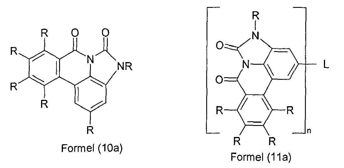
- Preferred embodiments of the formulas (10) and (11) are the compounds of the following formulas (10a) and (11a), wherein the symbols and indices used have the meanings given above.
- Preferred embodiments of the formulas (10a) and (11a) are the compounds of the following formulas (10b) and (11b), wherein the symbols and indices used have the meanings given above.
- Particularly preferred embodiments are the compounds of the following formulas (10c) and (11c), wherein the symbols and indices used have the meanings given above.
- Suitable aromatic or heteroaromatic ring systems are ortho, meta or para-phenylene, fluorene, spirobifluorene, pyridine, pyrimidine, triazine, carbazole, dibenzofuran, triphenylamine or combinations of two or three of these groups.
- the compounds according to the invention preferably have at least one group R other than hydrogen or deuterium, and / or a compound with n> 1.
- the radical R other than hydrogen is preferably selected from the group consisting of an aromatic or heteroaromatic ring system having 5 to 24 aromatic ring atoms, which may be substituted by one or more radicals R 1 . This also applies in particular to the radical R which is bonded to a nitrogen atom when Y is NR.
- Suitable aryl or heteroaryl groups of which the aromatic ring system is composed are preferably selected from the group consisting of benzene, naphthalene, phenanthrene, triphenylene, pyridine, thiophene, furan, pyrrole, carbazole, fluorene, benzofuran, benzothiophene, dibenzofuran, dibenzothiophene , Quinoline, isoquinoline, phenanthridine, phenanthroline, azacarbazole, imidazole and benzimidazole, each of which may be substituted with one or more R 1 .
- Further preferred radicals R are aromatic or heteroaromatic amino groups, where the aryl or heteroaryl groups may be substituted by one or more radicals R 1 .
- none of the aryl or heteroaryl groups forming the aromatic or heteroaromatic ring system or present in the aromatic or heteroaromatic amino group contains more than two aromatic six-membered rings fused directly together.
- the radicals R preferably contain no aromatic six-membered rings condensed directly together.
- An aryl or heteroaryl group having not more than two directly condensed aromatic six-membered rings are understood as meaning simple aryl or heteroaryl groups, such as, for example, benzene or pyridine, or aryl or heteroaryl groups having exactly two aromatic six-membered rings condensed together, for example naphthalene or quinoline , Furthermore, these are understood to mean heteroaryl groups in which aromatic five-membered rings and six-membered rings, but non-aromatic six-membered rings, are directly fused to one another, such as, for example, carbazole, dibenzofuran, dibenzothiophene or benzimidazole. Furthermore, phenanthrene or triphenylene may be suitable.
- Preferred groups R are selected from the group consisting of benzene, biphenyl, in particular ortho, meta or para biphenyl, terphenyl, in particular ortho, meta, para or branched terphenyl, quaterphenyl, in particular ortho, meta or para -linked, linear or branched quaterphenyl, fluorene, in particular 1-, 2-, 3- or 4-fluorene, spirobifluorene, in particular 1-, 2-, 3- or 4-spirobifluorene, 1- or 2-naphthalene, pyrrole, furan , Thiophene, indole, benzofuran, benzothiophene, carbazole, in particular 1-, 2-, 3- or 4-carbazole or N-carbazole, dibenzothiophene, in particular 1-, 2-, 3- or 4-dibenzothiophene, dibenzofuran, in particular 1- , 2-, 3- or 4-dibenzofuran, 1,3,5-triazine
- R is an aromatic or heteroaromatic ring system
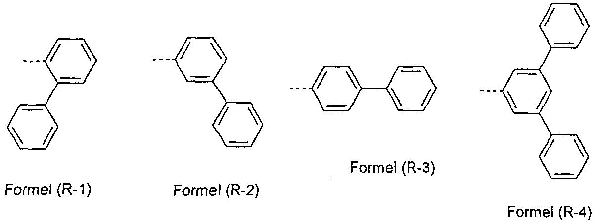
- this is preferably selected from the groups of the following formulas (R-1) to (R-33), wherein the dashed bond indicates attachment to the backbone and the groups may each be substituted by one or more R 1 , but are preferably unsubstituted.
- Low-electron heteroaromatics are five-membered heteroaromatics having at least two heteroatoms or six-membered heteroaromatics, to each of which one or more aromatic or heteroaromatic groups may be fused, for example substituted or unsubstituted imidazoles, pyrazoles, thiazoles, oxazoles, oxadiazoles, triazoles, pyridines, pyrazines, pyrimidines, Pyridazines, triazines, benzimidazoles, etc., in particular those as they are listed below.
- Preferred groups R and / or L are furthermore also substituted or unsubstituted condensed aryl groups, in particular naphthalene, anthracene, pyrene, phenanthrene, triphenylene and benzanthracene.
- At least one substituent R is a group of the abovementioned formula (R-1) to (R-17) or formula (13), and / or at least one group L is a group of the abovementioned Formulas (17) to (19), wherein in each case two or three symbols A stand for N and the other symbols A stand for CR 1 .
- Particularly preferred groups R are therefore the groups of the following formulas (20) to (26), and particularly preferred groups L are the groups of the following formulas (27) to (34) wherein the symbols and indices used have the meanings given above.
- R 1 in this group is preferably an aromatic or heteroaromatic ring system having 5 to 24 aromatic ring atoms, which may be substituted by one or more alkyl groups having 1 to 10 C atoms, in particular phenyl, biphenyl, in particular ortho, meta or para biphenyl, terphenyl, in particular ortho, meta, para or branched terphenyl, or quaterphenyl, in particular ortho, meta, para or branched quaterphenyl.
- R 1 in these groups is preferably the same or different at each occurrence of H, D or an aromatic or heteroaromatic ring system having 5 to 24 aromatic ring atoms, which is replaced by a or more alkyl groups having 1 to 10 carbon atoms, in particular for H or phenyl, biphenyl, in particular ortho, meta or para biphenyl, Terphenyl, in particular ortho, meta, para or branched terphenyl, or quaterphenyl, in particular ortho, meta, para or branched quaterphenyl.
- the compounds of the formula (1) or the preferred embodiments are used as a matrix material for a fluorescent emitter or as a fluorescent emitter, it is preferred that at least one of the radicals R contains a group which is selected from Naphthalene, anthracene, phenanthrene, pyrene and / or benzanthracene, which may each be substituted by one or more groups R 1 .
- R is the same or different at each occurrence selected from the group consisting of H, a straight chain alkyl group having 1 to 10 carbon atoms or a branched or cyclic alkyl group having 3 to 10 carbon atoms, each having one or more R radicals 2 may be substituted, or an aromatic or heteroaromatic ring system having 5 to 18 aromatic ring atoms, which may be substituted in each case with one or more radicals R 2 .
- the alkyl groups preferably have not more than five carbon atoms, more preferably not more than 4 carbon atoms, most preferably not more than 1 carbon atom.
- compounds which are substituted by alkyl groups having up to 10 carbon atoms or which are substituted by oligoarylene groups, for example ortho, meta, para or branched terphenyl or quaterphenyl groups are also suitable are.
- Examples of preferred compounds according to the invention are the compounds depicted in the following table.
- the compounds according to the invention can be prepared by synthesis steps which are known in principle to the person skilled in the art, as shown schematically in Schemes 1 and 2.
- an ortho-substituted halobenzyl halide instead of the ortho-position halo-substituted carboxylic acid halide, an ortho-substituted halobenzyl halide can be used, as shown in Scheme 2.
- formulations of the compounds according to the invention are required. These formulations may be, for example, solutions, dispersions or emulsions. It may be preferable to use mixtures of two or more solvents for this purpose.
- Suitable and preferred solvents are, for example, toluene, anisole, o-, m- or p-xylene, methyl benzoate, mesitylene, tetralin, veratrol, THF, methyl THF, THP, chlorobenzene, dioxane, phenoxytoluene, in particular 3-phenoxytoluene, (-) -Fenchone, 1,2,3,5-tetramethylbenzene, 1,2,4,5-tetramethylbenzene, 1-methylnaphthalene, 2-methylbenzothiazole, 2-phenoxyethanol, 2-pyrrolidinone, 3-methylanisole, 4-methylanisole, 3,4 Dimethylanisole, 3,5-dimethylanisole, acetophenone, ⁇ -terpineol, benzothiazole, butylbenzoate, cumene, cyclohexanol, cyclohexanone, cyclohexylbenzene, decalin, dodec
- a further subject of the present invention is therefore a formulation containing a compound according to the invention and at least one further compound.
- the further compound may be for example a solvent, in particular one of the abovementioned solvents or a mixture of these solvents.
- the further connection can also be another organic or inorganic compound which is also used in the electronic device, for example an emitting compound, in particular a phosphorescent compound.
- Another object of the present invention is the use of the compounds of the invention in an electronic device, in particular in an organic electroluminescent device.
- the organic electroluminescent devices and the light-emitting electrochemical cells can be used for various applications, for example for monochrome or multicolor displays, for lighting applications or for medical and / or cosmetic applications, for example in phototherapy.
- An electronic device in the sense of the present invention is a device which contains at least one layer which contains at least one organic compound.
- the component may also contain inorganic materials or layers which are completely composed of inorganic materials.
- the electronic device is preferably selected from the group consisting of organic electroluminescent devices (OLEDs), organic integrated circuits (O-ICs), organic field-effect transistors (O-FETs), organic thin-film transistors (O-TFTs), organic light-emitting transistors ( O-LETs), organic solar cells (O-SCs), organic dye-sensitized solar cells (O-DSSC), organic optical detectors, organic photoreceptors, organic field quench devices (O-FQDs), light-emitting electrochemical cells (LECs), organic laser diodes (O-laser) and "organic plasmon emitting devices” ( Koller et al., Nature Photonics 2008, 1-4 ), preferably organic electroluminescent devices (OLEDs) and particularly preferably phosphorescent OLEDs.
- OLEDs organic electroluminescent devices
- O-ICs organic integrated circuits
- O-FETs organic field-effect transistors
- OF-TFTs organic thin-film transistors
- the organic electroluminescent device includes cathode, anode and at least one emitting layer. Except these layers can they also contain further layers, for example one or more hole injection layers, hole transport layers, hole blocking layers, electron transport layers, electron injection layers, exciton blocking layers, electron blocking layers and / or charge generation layers (charge generation layers). Likewise, intetlayers can be introduced between two emitting layers, which have, for example, an exciton-blocking function. It should be noted, however, that not necessarily each of these layers must be present. In this case, the organic electroluminescent device may contain an emitting layer, or it may contain a plurality of emitting layers.
- emission layers are present, they preferably have a total of a plurality of emission maxima between 380 nm and 750 nm, so that overall white emission results, ie in the emitting layers different emitting compounds are used, which can fluoresce or phosphoresce.
- white emission can be preferentially generated by using a blue emission layer and an emission layer emitting red and green, and these two emission layers can be separated from each other by a charge generation layer.
- the compound according to formula (1) can be used in different layers, depending on the exact structure. Preference is given to an organic electroluminescent device comprising a compound according to formula (1) or the preferred embodiments described above as matrix material for fluorescent or phosphorescent emitters, in particular for phosphorescent emitters, and / or in a hole blocking layer and / or in an electron transport layer and / or in an electron-blocking or exciton-blocking layer and / or in a hole transport layer, depending on the exact substitution.
- the organic electroluminescent device contains the compound according to formula (1) or the The above-described preferred embodiments in an optical coupling-out layer.
- An optical coupling-out layer is understood to be a layer which does not lie between the anode and the cathode, but which is applied to an electrode outside the actual device, for example between an electrode and a substrate, in order to improve the optical coupling-out.
- the compound according to the invention is used as matrix material for a fluorescent or phosphorescent compound, in particular for a phosphorescent compound, in an emitting layer.
- the organic electroluminescent device may contain an emitting layer, or it may contain a plurality of emitting layers, wherein at least one emitting layer contains at least one compound according to formula (1) as matrix material.
- the compound according to formula (1) or the preferred embodiments outlined above is used as the matrix material for an emitting compound in an emitting layer, it is preferably used in combination with one or more phosphorescent materials (triplet emitters).
- Phosphorescence in the sense of this invention is understood to mean the luminescence from an excited state with a spin multiplicity> 1, in particular from an excited triplet state.
- all luminescent complexes with transition metals or lanthanides, in particular all iridium, platinum and copper complexes are to be regarded as phosphorescent compounds.
- the mixture of the compound according to formula (1) or the above-described preferred embodiments and the emitting compound contains between 99 and 1 vol.%, Preferably between 98 and 10 vol.%, Particularly preferably between 97 and 60 vol. %, in particular between 95 and 80 vol .-% of the compound according to formula (1) or the above-described preferred embodiments based on the total mixture of emitter and matrix material. Accordingly, the mixture contains between 1 and 99% by volume, preferably between 2 and 90% by volume, more preferably between 3 and 40% by volume, in particular between 5 and 20% by volume, of the emitter relative to the total mixture of emitter and matrix material. Depending on the choice of the matrix material and a lower emitter concentration may be preferred, such as. B. in the application not disclosed EP 11002816.4 described.
- a further preferred embodiment of the present invention is the use of the compound of the formula (1) or of the above-described preferred embodiments as a matrix material for a phosphorescent emitter in combination with another matrix material.
- a further preferred embodiment of the present invention is the use of the compound according to formula (1) or according to the preferred embodiments as a matrix material for a phosphorescent emitter in combination with another matrix material.
- Particularly suitable matrix materials which can be used in combination with the compounds according to formula (1) or according to the preferred embodiments are aromatic ketones, aromatic phosphine oxides or aromatic sulfoxides or sulfones, eg. B. according to WO 2004/013080 . WO 2004/093207 .
- WO 2006/005627 or WO 2010/006680 Triarylamines, carbazole derivatives, e.g. B. CBP (N, N-bis-carbazolylbiphenyl) or in WO 2005/039246 . US 2005/0069729 . JP 2004/288381 .
- EP 1205527 or WO 2008/086851 disclosed carbazole derivatives, indolocarbazole derivatives, e.g. B. according to WO 2007/063754 or WO 2008/056746 , Indenocarbazole derivatives, e.g. B. according to WO 2010/136109 .
- WO 2011/000455 or WO 2013/041176 Azacarbazolderivate, z. B. according to EP 1617710 .
- JP 2005/347160 bipolar matrix materials, e.g. B. according to WO 2007/137725 , Silane, z. B. according to WO 005/111172 , Azaborole or Boronester, z. B. according to WO 2006/117052 , Triazine derivatives, e.g. B. according to WO 2010/015306 . WO 2007/063754 or WO 2008/056746 , Zinc complexes, e.g. B.
- Diazasilol- or tetraazasilol derivatives z. B. according to WO 2010/054729
- Diazaphosphole derivatives e.g. B. according to WO 2010/054730 bridged carbazole derivatives, e.g. B. according to US 2009/0136779 .
- WO 2010/050778 WO 2011/042107 .
- WO 2011/088877 or WO 2012/143080 Triphenylenderivaten, z. B. according to WO 2012/048781 , or lactams, e.g. B. according to WO 2011/116865 or WHERE 2011/137951
- a further phosphorescent emitter which emits shorter wavelength than the actual emitter, may be present as a co-host in the mixture.
- Suitable phosphorescent compounds are, in particular, compounds which emit light, preferably in the visible range, with suitable excitation and also contain at least one atom of atomic number greater than 20, preferably greater than 38 and less than 84, particularly preferably greater than 56 and less than 80, in particular a metal with this atomic number.
- Preferred phosphorescence emitters used are compounds containing copper, molybdenum, tungsten, rhenium, ruthenium, osmium, rhodium, iridium, palladium, platinum, silver, gold or europium, in particular compounds containing iridium, platinum or copper.
- the organic electroluminescent device according to the invention does not contain a separate hole injection layer and / or hole transport layer and / or hole blocking layer and / or electron transport layer, ie the emitting layer directly adjoins the hole injection layer or the anode, and / or the emitting layer directly adjoins the electron transport layer or the electron injection layer or the cathode, such as in WO 2005/053051 described.
- a metal complex which is the same or similar to the metal complex in the emitting layer, directly adjacent to the emitting layer as a hole transport or to use hole injection material, such as. In WO 2009/030981 described.
- the compound according to formula (1) or the above-described preferred embodiments is used as an electron transport material in an electron transport or electron injection layer.
- the emitting layer may be fluorescent or phosphorescent.
- the compound when used as an electron transport material, it may be preferred if it is doped, for example, with alkali metal complexes, such as. B. LiQ (Lithiumhydroxychinolinat).
- the compound according to formula (1) or the above-described preferred embodiments is used in a hole blocking layer.
- a hole blocking layer is understood as meaning a layer which directly adjoins an emitting layer on the cathode side.
- the compound according to formula (1) or the above-described preferred embodiments is used in a hole transport layer or in an electron blocking layer or exciton blocking layer.
- an organic electroluminescent device characterized in that one or more layers are coated with a sublimation process.
- the materials are vapor-deposited in vacuum sublimation systems at an initial pressure of less than 10 -5 mbar, preferably less than 10 -6 mbar. But it is also possible that the initial pressure is even lower, for example less than 10 -7 mbar.
- an organic electroluminescent device characterized in that one or more layers are coated with the OVPD (Organic Vapor Phase Deposition) method or with the aid of a carrier gas sublimation.
- the materials are applied at a pressure between 10 -5 mbar and 1 bar.
- OVJP Organic Vapor Jet Printing
- the materials are applied directly through a nozzle and thus structured (eg. MS Arnold et al., Appl. Phys. Lett. 2008, 92, 053301 ).
- an organic electroluminescent device characterized in that one or more layers of solution, such. B. by spin coating, or with any printing process, such.
- any printing process such as screen printing, flexographic printing, offset printing, LITI (Light Induced Thermal Imaging, thermal transfer printing), ink-jet printing (ink jet printing) or Nozzle Printing, are produced.
- soluble compounds are necessary, which are obtained for example by suitable substitution. These methods are particularly suitable for oligomers, dendrimers and polymers.
- hybrid processes are possible in which, for example, one or more layers are applied from solution and one or more further layers are vapor-deposited.
- the starting materials can be obtained from the companies ALDRICH or ABCR (palladium (II) acetate, tri-o-tolylphosphine, inorganics, solvents).
- the data for the educts known from the literature are the CAS numbers.
- Example 10 2- (bis - biphenyl - 4 - yl - amino) -8a - aza - benzo [fg] naphthacene-8, 9 - dione
- Example 11 - (2 - bromo - benzyl) - 3 - phenyl - 1, 3 - dihydro - benzoimidazol - 2-one
- the OLEDs have the following layer structure: substrate / hole transport layer (HTL) / intermediate layer (IL) / electron blocking layer (EBL) / emission layer (EML) / optional hole blocking layer (HBL) / electron transport layer (ETL) / optional electron injection layer (EIL) and finally a cathode.
- the cathode is formed by a 100 nm thick aluminum layer.
- Table 1 The exact structure of the OLEDs is shown in Table 1.
- the materials needed to make the OLEDs are shown in Table 3.
- a term such as "8a" refers to the corresponding compound from the above Example 8a. This applies analogously to all materials used according to the invention.
- the emission layer always consists of at least one matrix material (host material, host material) and an emitting dopant (dopant, emitter), which is admixed to the matrix material or the matrix materials by co-evaporation in a specific volume fraction.
- the electron transport layer may consist of a mixture of two materials.
- the OLEDs are characterized by default.
- the electroluminescence spectra are determined at a luminance of 1000 cd / m 2 and from this the CIE 1931 x and y color coordinates are calculated.
- the indication U1000 in Table 2 indicates the voltage required for a luminance of 1000 cd / m 2 .
- SE1000 and LE1000 indicate the power efficiency achieved at 1000 cd / m 2 .
- EQE1000 refers to external quantum efficiency at an operating luminance of 1000 cd / m 2 .
- the lifetime LD is defined as the time after which the luminance decreases from the start luminance to a certain proportion L1 when operating with a constant current.
Landscapes
- Chemical & Material Sciences (AREA)
- Organic Chemistry (AREA)
- Engineering & Computer Science (AREA)
- Materials Engineering (AREA)
- Physics & Mathematics (AREA)
- Spectroscopy & Molecular Physics (AREA)
- Electroluminescent Light Sources (AREA)
- Nitrogen Condensed Heterocyclic Rings (AREA)
- Heterocyclic Carbon Compounds Containing A Hetero Ring Having Oxygen Or Sulfur (AREA)
- Nitrogen And Oxygen Or Sulfur-Condensed Heterocyclic Ring Systems (AREA)
Description
- Die vorliegende Erfindung betrifft Materialien für die Verwendung in elektronischen Vorrichtungen, insbesondere in organischen Elektrolumineszenzvorrichtungen, sowie elektronische Vorrichtungen, insbesondere organische Elektrolumineszenzvorrichtungen enthaltend diese Materialien.
- Der Aufbau organischer Elektrolumineszenzvorrichtungen (OLEDs), in denen organische Halbleiter als funktionelle Materialien eingesetzt werden, ist beispielsweise in
US 4539507 ,US 5151629 ,EP 0676461 undWO 98/27136 - Die Eigenschaften phosphoreszierender OLEDs werden nicht nur von den eingesetzten Triplettemittern bestimmt. Hier sind insbesondere auch die anderen verwendeten Materialien, wie Matrixmaterialien, Lochblockiermaterialien, Elektronentransportmaterialien, etc. von besonderer Bedeutung. Verbesserungen dieser Materialien können somit auch zu deutlichen Verbesserungen der OLED-Eigenschaften führen. Auch für fluoreszierende OLEDs gibt es bei diesen Materialien noch Verbesserungsbedarf.
- Gemäß dem Stand der Technik werden unter anderem Lactame, z. B. gemäß
WO 2011/116865 ,DE 102005037115A1 oderWO 2011/137951 , als Matrixmaterialien für phosphoreszierende Emitter in organischen Elektrolumineszenzvorrichtungen eingesetzt. Generell sind hier weitere Verbesserungen wünschenswert, insbesondere in Bezug auf die Effizienz, die Lebensdauer und die thermische Stabilität der Materialien. - Aufgabe der vorliegenden Erfindung ist die Bereitstellung von Verbindungen, welche sich für den Einsatz in einer fluoreszierenden oder phosphoreszierenden OLED, insbesondere einer phosphoreszierenden OLED, eignen, beispielsweise als Matrixmaterial oder als Elektronentransport- bzw. Lochblockiermaterial. Insbesondere ist es die Aufgabe der vorliegenden Erfindung, Matrixmaterialien bereitzustellen, welche sich für grün und rot und gegebenenfalls auch blau phosphoreszierende OLEDs eignen.
- Überraschend wurde gefunden, dass die unten näher beschriebenen Verbindungen diese Aufgabe lösen und zu Verbesserungen der organischen Elektrolumineszenzvorrichtung führen, insbesondere hinsichtlich der Lebensdauer, der Effizienz und/oder der Betriebsspannung. Dies gilt insbesondere für rot und grün phosphoreszierende Elektrolumineszenzvorrichtungen, vor allem bei Einsatz der erfindungsgemäßen Verbindungen als Matrixmaterial. Die Materialien zeichnen sich weiterhin durch durch eine hohe Temperaturstabilität aus. Elektronische Vorrichtungen, insbesondere organische Elektrolumineszenzvorrichtungen, welche derartige Verbindungen enthalten, sind daher der Gegenstand der vorliegenden Erfindung.
- Gegenstand der vorliegenden Erfindung ist eine Verbindung gemäß Formel (1),

- X
- ist bei jedem Auftreten gleich oder verschieden CR oder N; oder genau zwei benachbarte Gruppen X stehen zusammen für eine Gruppe, ausgewählt aus NR, O oder S, wodurch ein Fünfring entsteht;
- Y
- ist bei jedem Auftreten gleich oder verschieden Z=Z, NR, wobei R ungleich H ist, O oder S;
- Z
- ist bei jedem Auftreten gleich oder verschieden CR oder N oder die benachbarten Gruppen Z=Z stehen zusammen für eine Gruppe der Formel (2),

- L
- ist für n = 1 nicht vorhanden und ist für n = 2 eine Einfachbindung oder eine bivalente Gruppe und für n = 3 eine trivalente Gruppe und für n = 4 eine tetravalente Gruppe und für n = 5 eine pentavalente Gruppe und für n = 6 eine hexavalente Gruppe; dabei ist L statt einer Gruppe R an einer beliebigen Stelle des Grundgerüsts gebunden;
- R
- ist bei jedem Auftreten gleich oder verschieden ausgewählt aus der Gruppe bestehend aus H, D, F, Cl, Br, I, CN, NO2, N(Ar1)2, N(R1)2, C(=O)Ar1, C(=O)R1, P(=O)(Ar1)2, einer geradkettigen Alkyl-, Alkoxy- oder Thioalkylgruppe mit 1 bis 40 C-Atomen oder einer verzweigten oder cyclischen Alkyl-, Alkoxy- oder Thioalkylgruppe mit 3 bis 40 C-Atomen oder einer Alkenyl- oder Alkinylgruppe mit 2 bis 40 C-Atomen, die jeweils mit einem oder mehreren Resten R1 substituiert sein kann, wobei eine oder mehrere nicht-benachbarte CH2-Gruppen durch R1C=CR1, C=C, Si(R1)2, C=O, C=S, C=NR1, P(=O)(R1), SO, SO2, NR1, O, S oder CONR1 ersetzt sein können und wobei ein oder mehrere H-Atome durch D, F, Cl, Br, I, CN oder NO2 ersetzt sein können, einem aromatischen oder heteroaromatischen Ringsystem mit 5 bis 60 aromatischen Ringatomen, das jeweils mit einem oder mehreren Resten R1 substituiert sein kann, einer Aryloxy- oder Heteroaryloxygruppe mit 5 bis 60 aromatischen Ringatomen, die mit einem oder mehreren Resten R1 substituiert sein kann, einer Aralkyl- oder Heteroaralkylgruppe mit 5 bis 60 aromatischen Ringatomen, die mit einem oder mehreren Resten R1 substituiert sein kann, oder einer Kombination dieser Systeme, wobei optional zwei oder mehr benachbarte Substituenten R ein monocyclisches oder polycyclisches, aliphatisches, aromatisches oder heteroaromatisches Ringsystem bilden können, das mit einem oder mehreren Resten R1 substituiert sein kann;
- Ar1
- ist bei jedem Auftreten gleich oder verschieden ein aromatisches oder heteroaromatisches Ringsystem mit 5-30 aromatischen Ringatomen, das mit einem oder mehreren nicht-aromatischen Resten R1 substituiert sein kann; dabei können zwei Reste Ar1, welche an dasselbe N-Atom oder P-Atom binden, auch durch eine Einfachbindung oder eine Brücke, ausgewählt aus N(R1), C(R1)2 oder O, miteinander verbrückt sein;
- R1
- ist ausgewählt aus der Gruppe bestehend aus H, D, F, CN, einem aliphatischem Kohlenwasserstoffrest mit 1 bis 20 C-Atomen, einem aromatischem oder heteroaromatischem Ringsystem mit 5 bis 30 aromatischen Ringatomen, in dem ein oder mehrere H-Atome durch D, F, Cl, Br, I, CN oder eine Alkylgruppe mit 1 bis 10 C-Atomen oder eine Alkenylgruppe mit 2 bis 10 C-Atomen ersetzt sein können, wobei zwei oder mehr benachbarte Substituenten R1 miteinander ein mono- oder polycyclisches, aliphatisches, aromatisches oder heteroaromatisches Ringsystem bilden können;
- n
- ist 1, 2, 3, 4, 5 oder 6;
- Eine Arylgruppe im Sinne dieser Erfindung enthält 6 bis 60 C-Atome; eine Heteroarylgruppe im Sinne dieser Erfindung enthält 2 bis 60 C-Atome und mindestens ein Heteroatom, mit der Maßgabe, dass die Summe aus C-Atomen und Heteroatomen mindestens 5 ergibt. Die Heteroatome sind bevorzugt ausgewählt aus N, O und/oder S. Dabei wird unter einer Arylgruppe bzw. Heteroarylgruppe entweder ein einfacher aromatischer Cyclus, also Benzol, bzw. ein einfacher heteroaromatischer Cyclus, beispielsweise Pyridin, Pyrimidin, Thiophen, etc., oder eine kondensierte (anellierte) Aryl- oder Heteroarylgruppe, beispielsweise Naphthalin, Anthracen, Phenanthren, Chinolin, Isochinolin, etc., verstanden. Miteinander durch Einfachbindung verknüpfte Aromaten, wie zum Beispiel Biphenyl, werden dagegen nicht als Aryl- oder Heteroarylgruppe, sondern als aromatisches Ringsystem bezeichnet.
- Ein aromatisches Ringsystem im Sinne dieser Erfindung enthält 6 bis 80 C-Atome im Ringsystem. Ein heteroaromatisches Ringsystem im Sinne dieser Erfindung enthält 2 bis 60 C-Atome und mindestens ein Heteroatom im Ringsystem, mit der Maßgabe, dass die Summe aus C-Atomen und Heteroatomen mindestens 5 ergibt. Die Heteroatome sind bevorzugt ausgewählt aus N, O und/oder S. Unter einem aromatischen oder heteroaromatischen Ringsystem im Sinne dieser Erfindung soll ein System verstanden werden, das nicht notwendigerweise nur Aryl- oder Heteroarylgruppen enthält, sondern in dem auch mehrere Aryl- oder Heteroarylgruppen durch eine nicht-aromatische Einheit, wie z. B. ein C-, N- oder O-Atom, verbunden sein können. So sollen beispielsweise auch Systeme wie Fluoren, 9,9'-Spirobifluoren, 9,9-Diarylfluoren, Triarylamin, Diarylether, Stilben, etc. als aromatische Ringsysteme im Sinne dieser Erfindung verstanden werden, und ebenso Systeme, in denen zwei oder mehrere Arylgruppen beispielsweise durch eine kurze Alkylgruppe verbunden sind.
- Im Rahmen der vorliegenden Erfindung werden unter einem aliphatischen Kohlenwasserstoffrest bzw. einer Alkylgruppe bzw. einer Alkenyl- oder Alkinylgruppe, die 1 bis 40 C-Atome enthalten kann, und in der auch einzelne H-Atome oder CH2-Gruppen durch die oben genannten Gruppen substituiert sein können, bevorzugt die Reste Methyl, Ethyl, n-Propyl, i-Propyl, n-Butyl, i-Butyl, s-Butyl, t-Butyl, 2-Methylbutyl, n-Pentyl, s-Pentyl, neo-Pentyl, Cyclopentyl, n-Hexyl, neo-Hexyl, Cyclohexyl, n-Heptyl, Cyclo-heptyl, n-Octyl, Cyclooctyl, 2-Ethylhexyl, Trifluormethyl, Pentafluorethyl, 2,2,2-Trifluorethyl, Ethenyl, Propenyl, Butenyl, Pentenyl, Cyclopentenyl, Hexenyl, Cyclohexenyl, Heptenyl, Cycloheptenyl, Octenyl, Cyclooctenyl, Ethinyl, Propinyl, Butinyl, Pentinyl, Hexinyl, Heptinyl oder Octinyl verstanden. Unter einer Alkoxygruppe mit 1 bis 40 C-Atomen werden bevorzugt Methoxy, Trifluormethoxy, Ethoxy, n-Propoxy, i-Propoxy, n-Butoxy, i-Butoxy, s-Butoxy, t-Butoxy, n-Pentoxy, s-Pentoxy, 2-Methylbutoxy, n-Hexoxy, Cyclohexyloxy, n-Heptoxy, Cycloheptyloxy, n-Octyloxy, Cyclooctyloxy, 2-Ethylhexyloxy, Pentafluorethoxy und 2,2,2-Trifluorethoxy verstanden. Unter einer Thioalkylgruppe mit 1 bis 40 C-Atomen werden insbesondere Methylthio, Ethylthio, n-Propylthio, i-Propylthio, n-Butylthio, i-Butylthio, s-Butylthio, t-Butylthio, n-Pentylthio, s-Pentylthio, n-Hexylthio, Cyclohexylthio, n-Heptylthio, Cycloheptylthio, n-Octylthio, Cyclooctylthio, 2-Ethylhexylthio, Trifluormethylthio, Pentafluorethylthio, 2,2,2-Trifluorethylthio, Ethenylthio, Propenylthio, Butenylthio, Pentenylthio, Cyclopentenylthio, Hexenylthio, Cyclohexenylthio, Heptenytthio, Cycloheptenylthio, Octenylthio, Cyclooctenylthio, Ethinylthio, Propinylthio, Butinylthio, Pentinylthio, Hexinylthio, Heptinylthio oder Octinylthio verstanden. Allgemein können Alkyl-, Alkoxy- oder Thioalkylgruppen gemäß der vorliegenden Erfindung geradkettig, verzweigt oder cyclisch sein, wobei eine oder mehrere nicht-benachbarte CH2-Gruppen durch die oben genannten Gruppen ersetzt sein können; weiterhin können auch ein oder mehrere H-Atome durch D, F, Cl, Br, I, CN oder NO2, bevorzugt F, Cl oder CN, weiter bevorzugt F oder CN, besonders bevorzugt CN ersetzt sein.
- Unter einem aromatischen oder heteroaromatischen Ringsystem mit 5 - 60 aromatischen Ringatomen, welches noch jeweils mit den oben genannten Resten R1 substituiert sein kann und welches über beliebige Positionen am Aromaten bzw. Heteroaromaten verknüpft sein kann, werden insbesondere Gruppen verstanden, die abgeleitet sind von Benzol, Naphthalin, Anthracen, Phenanthren, Pyren, Benzanthracen, Chrysen, Perylen, Fluoranthen, Naphthacen, Pentacen, Benzpyren, Biphenyl, Biphenylen, Terphenyl, Triphenylen, Fluoren, Spirobifluoren, Dihydrophenanthren, Dihydropyren, Tetrahydropyren, cis- oder trans-Indenofluoren, cis- oder trans-Indenocarbazol, cis- oder trans-Indolocarbazol, Truxen, Isotruxen, Spirotruxen, Spiroisotruxen, Furan, Benzofuran, Isobenzofuran, Dibenzofuran, Thiophen, Benzothiophen, Isobenzothiophen, Dibenzothiophen, Pyrrol, Indol, Isoindol, Carbazol, Pyridin, Chinolin, Isochinolin, Acridin, Phenanthridin, Benzo-5,6-chinolin, Benzo-6,7-chinolin, Benzo-7,8-chinolin, Phenothiazin, Phenoxazin, Pyrazol, Indazol, Imidazol, Benzimidazol, Naphthimidazol, Phenanthrimidazol, Pyridimidazol, Pyrazinimidazol, Chinoxalinimidazol, Oxazol, Benzoxazol, Naphthoxazol, Anthroxazol, Phenanthroxazol, Isoxazol, 1,2-Thiazol, 1,3-Thiazol, Benzothiazol, Pyridazin, Hexaazatriphenylen, Benzopyridazin, Pyrimidin, Benzpyrimidin, Chinoxalin, 1,5-Diazaanthracen, 2,7-Diazapyren, 2,3-Diazapyren, 1,6-Diazapyren, 1,8-Diazapyren, 4,5-Diazapyren, 4,5,9,10-Tetraazaperylen, Pyrazin, Phenazin, Phenoxazin, Phenothiazin, Fluorubin, Naphthyridin, Azacarbazol, Benzocarbolin, Phenanthrolin; 1,2,3-Triazol, 1,2,4-Triazol, Benzotriazol, 1,2,3-Oxadiazol, 1,2,4-Oxadiazol, 1,2,5-Oxadiazol, 1,3,4-Oxadiazol, 1,2,3-Thiadiazol, 1,2,4-Thiadiazol, 1,2,5-Thiadiazol, 1,3,4-Thiadiazol, 1,3,5-Triazin, 1,2,4-Triazin, 1,2,3-Triazin, Tetrazol, 1,2,4,5-Tetrazin, 1,2,3,4-Tetrazin, 1,2,3,5-Tetrazin, Purin, Pteridin, Indolizin und Benzothiadiazol oder Gruppen, die abgeleitet sind von Kombination dieser Systeme.
- In einer bevorzugten Ausführungsform der Erfindung steht Y für eine Gruppe Z=Z. Bevorzugt ist also eine Verbindung der folgenden Formel (3),

- In einer weiteren bevorzugten Ausführungsform der Erfindung steht die Gruppe Z=Z für eine Gruppe der Formel (2), so dass eine Verbindung der folgenden Formel (4) entsteht,

- Eine bevorzugte Ausführungsform der Verbindungen der Formel (3) und (4) sind die Verbindungen der folgenden Formel (5),

- In einer weiteren bevorzugten Ausführungsform der Erfindung ist n = 1, 2 oder 3. Für n > 1 ist die Gruppe L bevorzugt in der para-Position zum Stickstoff gebunden. Es handelt sich also für n > 1 bevorzugt um eine Struktur der folgenden Formel (6),

- In einer weiteren bevorzugten Ausführungsform der Erfindung steht maximal eine Gruppe X pro Cyclus für N und die weiteren Gruppen X stehen für CR. Besonders bevorzugt stehen alle Gruppen X für CR.
- Bevorzugt sind somit die Verbindungen der folgenden Formel (7) und (8),

- Bevorzugte Ausführungsformen der Formeln (7) und (8) sind die Verbindungen der folgenden Formeln (7a) und (8a),

- Bevorzugte Ausführungsformen der Formeln (7a) und (8a) sind die Verbindungen der folgenden Formeln (7b) und (8b),

- Besonders bevorzugte Ausführungsformen sind die Verbindungen der folgenden Formeln (7c) und (8c),

- In einer weiteren bevorzugten Ausführungsform der Erfindung steht Y für eine Gruppe NR. Eine weitere bevorzugte Ausführungsform der Verbindungen der Formel (4) sind daher die Verbindungen der folgenden Formel (9),

- Bevorzugte Ausführungsformen der Verbindungen der Formel (9) sind die Verbindungen der folgenden Formeln (10) und (11),

- Bevorzugte Ausführungsformen der Formeln (10) und (11) sind die Verbindungen der folgenden Formeln (10a) und (11 a),
- Bevorzugte Ausführungsformen der Formeln (10a) und (11a) sind die Verbindungen der folgenden Formeln (10b) und (11b),

- Besonders bevorzugte Ausführungsformen sind die Verbindungen der folgenden Formeln (10c) und (11 c),

- Bevorzugt sind weiterhin Strukturen, in denen der Rest R, der in Formel (9) bis (11) und (10a) bis (11 c) an den Stickstoff gebunden ist, für eine Gruppe C(=O)Ar1 steht, die mit einem benachbarten Rest R einen Ring bildet. Dadurch sind dann Verbindungen der folgenden Formeln (12) zugänglich,

- Bevorzugt steht L in den Verbindungen der Formel (1) bzw. den oben aufgeführten bevorzugten Verbindungen für n = 2 für eine Einfachbindung, CR2, O, NR oder C(=O) oder für n = 3 für N oder für n ≥ 2 für für ein aromatisches oder heteroaromatisches Ringsystem mit 5 bis 24 aromatischen Ringatomen, das mit einem oder mehreren Resten R substituiert sein kann. Geeignete aromatische oder heteroaromatische Ringsysteme sind ortho-, meta- oder para-Phenylen, Fluoren, Spirobifluoren, Pyridin, Pyrimidin, Triazin, Carbazol, Dibenzofuran, Triphenylamin oder Kombinationen aus zwei oder drei dieser Gruppen. Dabei ist für n = 2 das aromatische bzw. heteroaromatische Ringsystem ein bivalentes System, für n = 3 ein trivalentes System, etc.. Besonders bevorzugt ist n = 2, und L steht für eine Einfachbindung.
- Bevorzugt weisen die erfindungsgemäßen Verbindungen mindestens eine Gruppe R ungleich Wasserstoff oder Deuterium auf, und/oder es handelt sich um eine Verbindung mit n >1.
- Der Rest R ungleich Wasserstoff ist bevorzugt ausgewählt aus der Gruppe bestehend aus einem aromatischen oder heteroaromatischen Ringsystem mit 5 bis 24 aromatischen Ringatomen, welches durch einen oder mehrere Reste R1 substituiert sein kann. Dies gilt insbesondere auch für den Rest R, der an ein Stickstoffatom gebunden ist, wenn Y für NR steht. Geeignete Aryl- bzw. Heteroarylgruppen, aus denen das aromatische Ringsystem zusammengesetzt sind, sind bevorzugt ausgewählt aus der Gruppe bestehend aus Benzol, Naphthalin, Phenanthren, Triphenylen, Pyridin, Thiophen, Furan, Pyrrol, Carbazol, Fluoren, Benzofuran, Benzothiophen, Dibenzofuran, Dibenzothiophen, Chinolin, Isochinolin, Phenanthridin, Phenanthrolin, Azacarbazol, Imidazol und Benzimidazol, welche jeweils mit einem oder mehreren Resten R1 substituiert sein können. Weiterhin bevorzugte Reste R sind aromatische bzw. heteroaromatische Aminogruppen, wobei die Aryl- bzw. Heteroarylgruppen durch einen oder mehrere Reste R1 substituiert sein können.
- Wenn die erfindungsgemäße Verbindung als Matrixmaterial für einen phosphoreszierenden Emitter eingesetzt wird, enthält bevorzugt keine der Aryl- oder Heteroarylgruppen, die das aromatische bzw. heteroaromatische Ringsystem bilden oder die in der aromatischen bzw. heteroaromatischen Aminogruppe vorliegen, mehr als zwei direkt aneinander kondensierte aromatische Sechsringe. Bevorzugt enthalten die Reste R überhaupt keine direkt aneinander kondensierten aromatischen Sechsringe. Unter einer Aryl- oder Heteroarylgruppe mit nicht mehr als zwei direkt aneinander kondensierten aromatischen Sechsringen werden einfache Aryl- oder Heteroarylgruppen, wie zum Beispiel Benzol oder Pyridin, oder Aryl- oder Heteroarylgruppen mit genau zwei aneinander kondensierten aromatischen Sechsringen, wie zum Beispiel Naphthalin oder Chinolin verstanden. Weiterhin werden hierunter Heteroarylgruppen verstanden, in denen aromatische Fünfringe und Sechsringe, aber nicht aromatische Sechsringe direkt aneinander ankondensiert sind, wie zum Beispiel Carbazol, Dibenzofuran, Dibenzothiophen oder Benzimidazol. Weiterhin können auch Phenanthren oder Triphenylen geeignet sein.
- Bevorzugte Gruppen R sind ausgewählt aus der Gruppe bestehend aus Benzol, Biphenyl, insbesondere ortho-, meta- oder para-Biphenyl, Terphenyl, insbesondere ortho-, meta-, para- oder verzweigtes Terphenyl, Quaterphenyl, insbesondere ortho-, meta- oder para-verknüpftes, lineares oder verzweigtes Quaterphenyl, Fluoren, insbesondere 1-, 2-, 3- oder 4-Fluoren, Spirobifluoren, insbesondere 1-, 2-, 3- oder 4-Spirobifluoren, 1-oder 2-Naphthalin, Pyrrol, Furan, Thiophen, Indol, Benzofuran, Benzothiophen, Carbazol, insbesondere 1-, 2-, 3- oder 4-Carbazol oder N-Carbazol, Dibenzothiophen, insbesondere 1-, 2-, 3- oder 4-Dibenzothiophen, Dibenzofuran, insbesondere 1-, 2-, 3- oder 4-Dibenzofuran, 1,3,5-Triazin, Pyridin, Pyrimidin, Pyrazin, Pyridazin, Indenocarbazol, verbrücktes Carbazol, Indolocarbazol, Phenanthren, Triphenylen oder Kombinationen aus zwei oder drei dieser Gruppen. Dabei können diese Gruppen jeweils durch einen oder mehrere Reste R1 substituiert sein.
- Wenn R für ein aromatisches bzw. heteroaromatisches Ringsystem steht, dann ist dieses bevorzugt ausgewählt aus den Gruppen der folgenden Formeln (R-1) bis (R-33),


- Wenn die erfindungsgemäßen Verbindungen als Elektronentransportmaterial verwendet werden, ist es bevorzugt, wenn mindestens eine der Gruppen R und/oder L für ein elektronenarmes heteroaromatisches Ringsystem oder -C(=O)Ar1 oder -P(=O)(Ar1)2 steht. Elektronenarme Heteroaromaten sind erfindungsgemäß Fünfringheteroaromaten mit mindestens zwei Heteroatomen oder Sechsringheteroaromaten, an die jeweils noch ein oder mehrere aromatische oder heteroaromatische Gruppen ankondensiert sein können, zum Beispiel substituierte oder unsubstituierte Imidazole, Pyrazole, Thiazole, Oxazole, Oxadiazole, Triazole, Pyridine, Pyrazine, Pyrimidine, Pyridazine, Triazine, Benzimidazole, etc., insbesondere solche, wie sie im Folgenden aufgeführt sind. Bevorzugte Gruppen R und/oder L sind weiterhin auch substituierte oder unsubstituierte kondensierte Arylgruppen, insbesondere Naphthalin, Anthracen, Pyren, Phenanthren, Triphenylen und Benzanthracen.
- Wenn die erfindungsgemäße Verbindung bzw. die oben aufgeführten bevorzugten Verbindungen als Matrixmaterial für einen phosphoreszierenden Emitter oder als Elektronentransportmaterial eingesetzt wird, ist es weiterhin bevorzugt, wenn mindestens eine Gruppe R eine einfache aromatische Gruppe oder eine elektronenarme Gruppe darstellt, insbesondere ausgewählt aus Strukturen gemäß den folgenden Formeln (13) bis (16) für R oder den Formeln (17), (18) oder (19) für L,


- A ist bei jedem Auftreten gleich oder verschieden CR1 oder N, mit der Maßgabe, dass keine, eine, zwei oder drei Gruppen A für N stehen;
- Ar2 ist gleich oder verschieden bei jedem Auftreten ein bivalentes aromatisches oder heteroaromatisches Ringsystem mit 5 bis 16 C-Atomen, welches durch einen oder mehrere Reste R1 substituiert sein kann;
- m ist bei jedem Auftreten gleich oder verschieden 0 oder 1.
- Als Matrixmaterial für phosphoreszierende Emitter sind weiterhin auch generell die oben aufgeführten aromatischen und heteroaromatischen Ringsysteme bevorzugt, die allgemein als bevorzugte Reste R genannt sind.
- In einer besonders bevorzugten Ausführungsform der Erfindung steht mindestens ein Substituent R für eine Gruppe der oben genannten Formel (R-1) bis (R-17) oder Formel (13), und/oder mindestens eine Gruppe L steht für eine Gruppe der oben genannten Formeln (17) bis (19), wobei jeweils zwei oder drei Symbole A für N stehen und die anderen Symbole A für CR1 stehen. Besonders bevorzugte Gruppen R sind daher die Gruppen der folgenden Formeln (20) bis (26), und besonders bevorzugte Gruppen L sind die Gruppen der folgenden Formeln (27) bis (34),
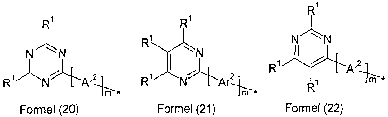


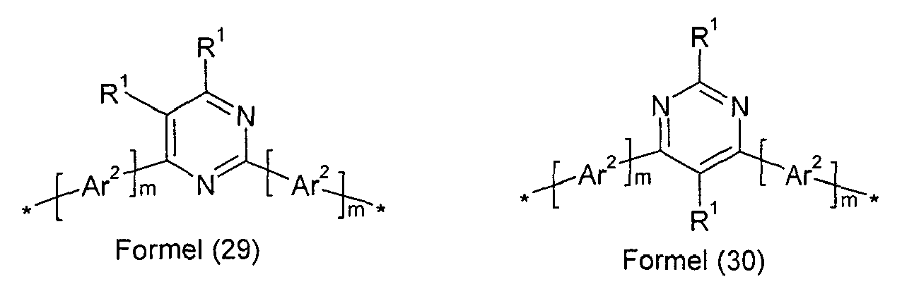


- Wenn R für eine Gruppe der Formel (20) steht, dann steht R1 in dieser Gruppe bevorzugt für ein aromatisches oder heteroaromatisches Ringsystem mit 5 bis 24 aromatischen Ringatomen, welches durch eine oder mehrere Alkylgruppen mit 1 bis 10 C-Atomen substituiert sein kann, insbesondere für Phenyl, Biphenyl, insbesondere ortho-, meta- oder para-Biphenyl, Terphenyl, insbesondere ortho-, meta-, para- oder verzweigtes Terphenyl, oder Quaterphenyl, insbesondere ortho-, meta-, para- oder verzweigtes Quaterphenyl.
- Wenn R für eine Gruppe der Formel (21) bis (34) steht, dann steht R1 in diesen Gruppen bevorzugt gleich oder verschieden bei jedem Auftreten für H, D oder ein aromatisches oder heteroaromatisches Ringsystem mit 5 bis 24 aromatischen Ringatomen, welches durch eine oder mehrere Alkylgruppen mit 1 bis 10 C-Atomen substituiert sein kann, insbesondere für H oder Phenyl, Biphenyl, insbesondere ortho-, meta- oder para-Biphenyl, Terphenyl, insbesondere ortho-, meta-, para- oder verzweigtes Terphenyl, oder Quaterphenyl, insbesondere ortho-, meta-, para- oder verzweigtes Quaterphenyl.
- Wenn die erfindungsgemäße Verbindung als Matrixmaterial für einen phosphoreszierenden Emitter eingesetzt wird, kann es weiterhin bevorzugt sein, wenn mindestens ein Substituent R ausgewählt ist aus der Gruppe bestehend aus Triaryl- bzw. Heteroarylaminderivaten, Carbazolderivaten, Indenocarbazolderivaten, Indolocarbazolderivaten, Azacarbazolderivaten, Indolderivaten, Furanderivaten, Benzofuranderivaten, Dibenzofuranderivaten, Thiophenderivaten, Benzothiophenderivaten oder Dibenzothiophenderivaten, welche jeweils durch einen oder mehrere Reste R1 substituiert sein können, oder mindestens ein Substituent R steht für -N(Ar1)2. Diese Gruppen sind bevorzugt ausgewählt aus den Gruppen der folgenden Formeln (35) bis (59),


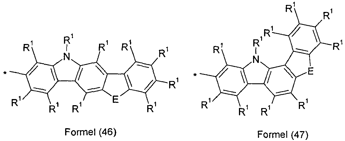


- E ist ausgewählt aus der Gruppe bestehend aus C(R1)2, NR1, O oder S;
- G ist ausgewählt aus der Gruppe bestehend aus NR1, O oder S.
- Die oben genannten bevorzugten Ausführungsformen können beliebig miteinander kombiniert werden. In einer besonders bevorzugten Ausführungsform der Erfindung treten die oben genannten Bevorzugungen gleichzeitig auf.
- Wenn die Verbindungen der Formel (1) bzw. die bevorzugten Ausführungsformen als Matrixmaterial für einen fluoreszierenden Emitter oder als fluoreszierender Emitter verwendet werden, ist es bevorzugt, wenn mindestens einer der Reste R eine Gruppe enthält, die ausgewählt ist aus Naphthalin, Anthracen, Phenanthren, Pyren und/oder Benzanthracen, welches jeweils noch durch eine oder mehrere Gruppen R1 substituiert sein kann.
- In einer bevorzugten Ausführungsform der Erfindung sind die Reste R in den erfindungsgemäßen Verbindungen, die nicht für die oben genannten Gruppen stehen, gleich oder verschieden bei jedem Auftreten ausgewählt aus der Gruppe bestehend aus H, D, F, CN, N(Ar2)2, C(=O)Ar2, einer geradkettigen Alkyl- oder Alkoxygruppe mit 1 bis 10 C-Atomen oder einer verzweigten oder cyclischen Alkyl- oder Alkoxygruppe mit 3 bis 10 C-Atomen oder einer Alkenylgruppe mit 2 bis 10 C-Atomen, die jeweils mit einem oder mehreren Resten R2 substituiert sein kann, wobei eine oder mehrere nicht-benachbarte CH2-Gruppen durch O ersetzt sein können und wobei ein oder mehrere H-Atome durch D oder F ersetzt sein können oder einem aromatischen oder heteroaromatischen Ringsystem mit 5 bis 30 aromatischen Ringatomen, das jeweils mit einem oder mehreren Resten R2 substituiert sein kann. Besonders bevorzugt ist R gleich oder verschieden bei jedem Auftreten ausgewählt aus der Gruppe bestehend aus H, einer geradkettigen Alkylgruppe mit 1 bis 10 C-Atomen oder einer verzweigten oder cyclischen Alkylgruppe mit 3 bis 10 C-Atomen, die jeweils mit einem oder mehreren Resten R2 substituiert sein kann, oder einem aromatischen oder heteroaromatischen Ringsystem mit 5 bis 18 aromatischen Ringatomen, das jeweils mit einem oder mehreren Resten R2 substituiert sein kann.
- Dabei haben für Verbindungen, die durch Vakuumverdampfung verarbeitet werden, die Alkylgruppen bevorzugt nicht mehr als fünf C-Atome, besonders bevorzugt nicht mehr als 4 C-Atome, ganz besonders bevorzugt nicht mehr als 1 C-Atom. Für Verbindungen, die aus Lösung verarbeitet werden, eignen sich auch Verbindungen, die mit Alkylgrupp'en mit bis zu 10 C-Atomen substituiert sind oder die mit Oligoarylengruppen, beispielsweise ortho-, meta-, para- oder verzweigten Terphenyl- oder Quaterphenylgruppen, substituiert sind.
- In einer besonders bevorzugten Ausführungsform der Erfindung treten die oben genannten Bevorzugungen gleichzeitig auf.
- Beispiele für bevorzugte erfindungsgemäße Verbindungen sind die in der folgenden Tabelle abgebildeten Verbindungen.


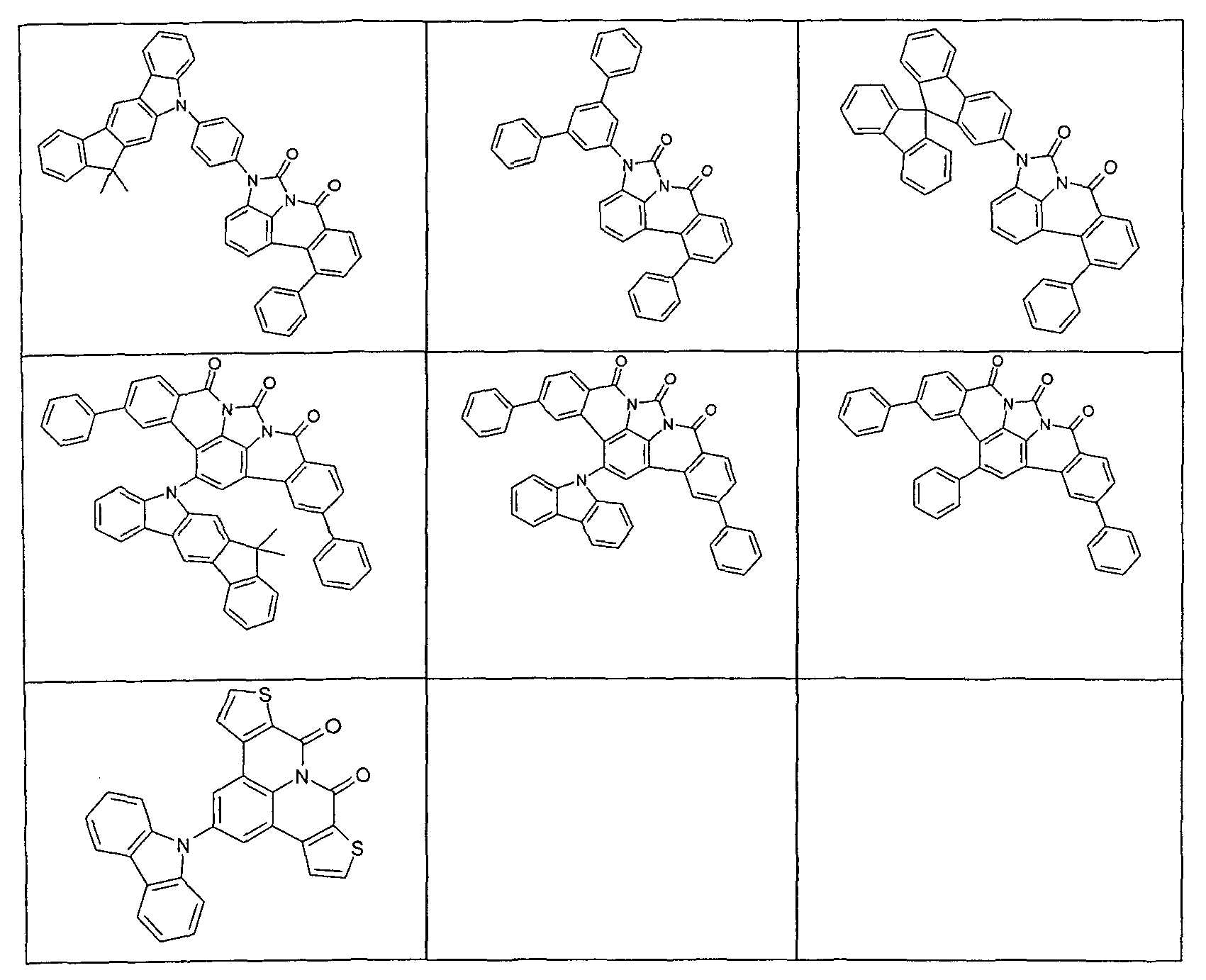
- Die erfindungsgemäßen Verbindungen können nach dem Fachmann prinzipiell bekannten Syntheseschritten dargestellt werden, wie in Schema 1 und 2 schematisch dargestellt.
- Wie in Schema 1 dargestellt, erhält man nach einer Schmidt-Reaktion und anschließender Reduktion das entsprechende 5,6-Dihydrophenanthridin-Derivat (a), das unter Verwendung von in ortho-Stellung Halogen-substituiertem Carbonsäurehalogenid und anschließender Palladium-katalysierter intramolekularer Cyclisierung zum 8a-Aza-benzo[fg]naphthacen-8,9-dion umgesetzt wird. Durch Halogenierung, beispielsweise Bromierung mit NBS, kann dieser Grundbaustein halogeniert werden. In einer Folgereaktion kann beispielsweise mit einer Suzuki-Kupplung, einer Buchwald- oder Ullmann-Reaktion zum gewünschten Derivat umgesetzt werden.

- Alternativ kann an Stelle des in ortho-Position Halogen-substituierten Carbonsäurehalogenids ein ortho-substituiertes Halogen-benzylhalogenid eingesetzt werden, wie in Schema 2 dargestellt.

- Ein weiterer Gegenstand der vorliegenden Erfindung ist ein Verfahren zur Herstellung einer Verbindung gemäß Formel (1), umfassend die Schritte:
- a) Herstellung des halogenierten Grundgerüsts der Verbindung der Formel (1), wobei das Halogen bevorzugt Chlor, Brom oder Iod ist; und
- b) Einführung mindestens eines Substituenten R in der Position des Halogens.
- Für die Verarbeitung der erfindungsgemäßen Verbindungen aus flüssiger Phase, beispielsweise durch Spin-Coating oder durch Druckverfahren, sind Formulierungen der erfindungsgemäßen Verbindungen erforderlich. Diese Formulierungen können beispielsweise Lösungen, Dispersionen oder Emulsionen sein. Es kann bevorzugt sein, hierfür Mischungen aus zwei oder mehr Lösemitteln zu verwenden. Geeignete und bevorzugte Lösemittel sind beispielsweise Toluol, Anisol, o-, m- oder p-Xylol, Methylbenzoat, Mesitylen, Tetralin, Veratrol, THF, Methyl-THF, THP, Chlorbenzol, Dioxan, Phenoxytoluol, insbesondere 3-Phenoxytoluol, (-)-Fenchon, 1,2,3,5-Tetramethylbenzol, 1,2,4,5-Tetramethylbenzol, 1-Methylnaphthalin, 2-Methylbenzothiazol, 2-Phenoxyethanol, 2-Pyrrolidinon, 3-Methylanisol, 4-Methylanisol, 3,4-Dimethylanisol, 3,5-Dimethylanisol, Acetophenon, α-Terpineol, Benzothiazol, Butylbenzoat, Cumol, Cyclohexanol, Cyclohexanon, Cyclohexylbenzol, Decalin, Dodecylbenzol, Ethylbenzoat, Indan, Methylbenzoat, NMP, p-Cymol, Phenetol, 1,4-Diisopropylbenzol, Dibenzylether, Diethylenglycolbutylmethylether, Triethylenglycolbutylmethylether, Diethylenglycoldibutylether, Triethylenglycoldimethylether, Diethylenglycolmonobutylether, Tripropyleneglycoldimethylether, Tetraethyleneglycoldimethylether, 2-lsopropylnaphthalin, Pentylbenzol, Hexylbenzol, Heptylbenzol, Octylbenzol, 1,1-Bis(3,4-dimethylphenyl)ethan oder Mischungen dieser Lösemittel.
- Ein weiterer Gegenstand der vorliegenden Erfindung ist daher eine Formulierung, enthaltend eine erfindungsgemäße Verbindung und mindestens eine weitere Verbindung. Die weitere Verbindung kann beispielsweise ein Lösemittel sein, insbesondere eines der oben genannten Lösemittel oder eine Mischung dieser Lösemittel. Die weitere Verbindung kann aber auch eine weitere organische oder anorganische Verbindung sein, die ebenfalls in der elektronischen Vorrichtung eingesetzt wird, beispielsweise eine emittierende Verbindung, insbesondere eine phosphoreszierende Verbindung.
- Ein weiterer Gegenstand der vorliegenden Erfindung ist die Verwendung der erfindungsgemäßen Verbindungen in einer elektronischen Vorrichtung, insbesondere in einer organischen Elektrolumineszenzvorrichtung.
- Die organischen Elektrolumineszenzvorrichtungen und die lichtemittierenden elektrochemischen Zellen können für verschiedene Anwendungen eingesetzt werden, beispielsweise für einfarbige oder mehrfarbige Displays, für Beleuchtungsanwendungen oder für medizinische und/oder kosmetische Anwendungen, beispielsweise in der Phototherapie.
- Eine elektronische Vorrichtung im Sinne der vorliegenden Erfindung ist eine Vorrichtung, welche mindestens eine Schicht enthält, die mindestens eine organische Verbindung enthält. Das Bauteil kann dabei auch anorganische Materialien enthalten oder auch Schichten, welche vollständig aus anorganischen Materialien aufgebaut sind.
- Die elektronische Vorrichtung ist bevorzugt ausgewählt aus der Gruppe bestehend aus organischen Elektrolumineszenzvorrichtungen (OLEDs), organischen integrierten Schaltungen (O-ICs), organischen Feld-Effekt-Transistoren (O-FETs), organischen Dünnfilmtransistoren (O-TFTs), organischen lichtemittierenden Transistoren (O-LETs), organischen Solarzellen (O-SCs), organischen farbstoffsensibilisierten Solarzellen (O-DSSC), organischen optischen Detektoren, organischen Photorezeptoren, organischen Feld-Quench-Devices (O-FQDs), lichtemittierenden elektrochemischen Zellen (LECs), organischen Laserdioden (O-Laser) und "organic plasmon emitting devices" (D. M. Koller et al., Nature Photonics 2008, 1-4), bevorzugt organischen Elektrolumineszenzvorrichtungen (OLEDs) und besonders bevorzugt phosphoreszierenden OLEDs.
- Die organische Elektrolumineszenzvorrichtung enthält Kathode, Anode und mindestens eine emittierende Schicht. Außer diesen Schichten kann sie noch weitere Schichten enthalten, beispielsweise jeweils eine oder mehrere Lochinjektionsschichten, Lochtransportschichten, Lochblockierschichten, Elektronentransportschichten, Elektroneninjektionsschichten, Exzitonenblockierschichten, Elektronenblockierschichten und/oder Ladungserzeugungsschichten (Charge-Generation Layers). Ebenso können zwischen zwei emittierende Schichten Intetlayer eingebracht sein, welche beispielsweise eine exzitonenblockierende Funktion aufweisen. Es sei aber darauf hingewiesen, dass nicht notwendigerweise jede dieser Schichten vorhanden sein muss. Dabei kann die organische Elektrolumineszenzvorrichtung eine emittierende Schicht enthalten, oder sie kann mehrere emittierende Schichten enthalten. Wenn mehrere Emissionsschichten vorhanden sind, weisen diese bevorzugt insgesamt mehrere Emissionsmaxima zwischen 380 nm und 750 nm auf, so dass insgesamt weiße Emission resultiert, d. h. in den emittierenden Schichten werden verschiedene emittierende Verbindungen verwendet, die fluoreszieren oder phosphoreszieren können. Insbesondere bevorzugt sind Systeme mit drei emittierenden Schichten, wobei die drei Schichten blaue, grüne und orange oder rote Emission zeigen (für den prinzipiellen Aufbau siehe z. B.
WO 2005/011013 ). Weiterhin lässt sich weiße Emission bevorzugt erzeugen durch Verwendung einer blauen Emissionsschicht und einer Emissionsschicht, die rot und grün emittiert, wobei diese beiden Emissionsschichten durch eine Ladungserzeugungsschicht voneinander separiert sein können. - Die Verbindung gemäß Formel (1) kann dabei in unterschiedlichen Schichten eingesetzt werden, je nach genauer Struktur. Bevorzugt ist eine organische Elektrolumineszenzvorrichtung, enthaltend eine Verbindung gemäß Formel (1) bzw. die oben ausgeführten bevorzugten Ausführungsformen als Matrixmaterial für fluoreszierende oder phosphoreszierende Emitter, insbesondere für phosphoreszierende Emitter, und/oder in einer Lochblockierschicht und/oder in einer Elektronentransportschicht und/oder in einer elektronenblockierenden bzw. exzitonenblockierenden Schicht und/oder in einer Lochtransportschicht, je nach genauer Substitution.
- In einer weiteren Ausführungsform der Erfindung enthält die organische Elektrolumineszenzvorrichtung die Verbindung gemäß Formel (1) bzw. die oben ausgeführten bevorzugten Ausführungsformen in einer optischen Auskopplungsschicht. Unter einer optischen Auskopplungsschicht wird dabei eine Schicht verstanden, die nicht zwischen der Anode und der Kathode liegt, sondern die außerhalb der eigentlichen Vorrichtung auf eine Elektrode aufgebracht wird, beispielsweise zwischen einer Elektrode und einem Substrat, um die optische Auskopplung zu verbessern.
- In einer bevorzugten Ausführungsform der Erfindung wird die erfindungsgemäße Verbindung als Matrixmaterial für eine fluoreszierende oder phosphoreszierende Verbindung, insbesondere für eine phosphoreszierende Verbindung, in einer emittierenden Schicht eingesetzt. Dabei kann die organische Elektrolumineszenzvorrichtung eine emittierende Schicht enthalten, oder sie kann mehrere emittierende Schichten enthalten, wobei mindestens eine emittierende Schicht mindestens eine Verbindung gemäß Formel (1) als Matrixmaterial enthält.
- Wenn die Verbindung gemäß Formel (1) bzw. die oben ausgeführten bevorzugten Ausführungsformen als Matrixmaterial für eine emittierende Verbindung in einer emittierenden Schicht eingesetzt wird, wird sie bevorzugt in Kombination mit einem oder mehreren phosphoreszierenden Materialien (Triplettemitter) eingesetzt. Unter Phosphoreszenz im Sinne dieser Erfindung wird die Lumineszenz aus einem angeregten Zustand mit Spinmultiplizität > 1, insbesondere aus einem angeregten Triplettzustand verstanden. Im Sinne dieser Anmeldung sollen alle lumineszierenden Komplexe mit Übergangsmetallen oder Lanthaniden, insbesondere alle Iridium-, Platin- und Kupferkomplexe als phosphoreszierende Verbindungen angesehen werden.
- Die Mischung aus der Verbindung gemäß Formel (1) bzw. der oben ausgeführten bevorzugten Ausführungsformen und der emittierenden Verbindung enthält zwischen 99 und 1 Vol.-%, vorzugsweise zwischen 98 und 10 Vol.-%, besonders bevorzugt zwischen 97 und 60 Vol.-%, insbesondere zwischen 95 und 80 Vol.-% der Verbindung gemäß Formel (1) bzw. der oben ausgeführten bevorzugten Ausführungsformen bezogen auf die Gesamtmischung aus Emitter und Matrixmaterial. Entsprechend enthält die Mischung zwischen 1 und 99 Vol.-%, vorzugsweise zwischen 2 und 90 Vol.-%, besonders bevorzugt zwischen 3 und 40 Vol.-%, insbesondere zwischen 5 und 20 Vol.-% des Emitters bezogen auf die Gesamtmischung aus Emitter und Matrixmaterial. Je nach Wahl des Matrixmaterials kann auch eine geringere Emitterkonzentration bevorzugt sein, wie z. B. in der nicht offen gelegten Anmeldung
EP 11002816.4 - Eine weitere bevorzugte Ausführungsform der vorliegenden Erfindung ist der Einsatz der Verbindung gemäß Formel (1) bzw. der oben ausgeführten bevorzugten Ausführungsformen als Matrixmaterial für einen phosphoreszierenden Emitter in Kombination mit einem weiteren Matrixmaterial. Eine weitere bevorzugte Ausführungsform der vorliegenden Erfindung ist der Einsatz der Verbindung gemäß Formel (1) bzw. gemäß den bevorzugten Ausführungsformen als Matrixmaterial für einen phosphoreszierenden Emitter in Kombination mit einem weiteren Matrixmaterial. Besonders geeignete Matrixmaterialien, welche in Kombination mit den Verbindungen gemäß Formel (1) bzw. gemäß den bevorzugten Ausführungsformen eingesetzt werden können, sind aromatische Ketone, aromatische Phosphinoxide oder aromatische Sulfoxide oder Sulfone, z. B. gemäß
WO 2004/013080 ,WO 2004/093207 ,WO 2006/005627 oderWO 2010/006680 , Triarylamine, Carbazolderivate, z. B. CBP (N,N-Bis-carbazolylbiphenyl) oder die inWO 2005/039246 ,US 2005/0069729 ,JP 2004/288381 EP 1205527 oderWO 2008/086851 offenbarten Carbazolderivate, Indolocarbazolderivate, z. B. gemäßWO 2007/063754 oderWO 2008/056746 , Indenocarbazolderivate, z. B. gemäßWO 2010/136109 ,WO 2011/000455 oderWO 2013/041176 , Azacarbazolderivate, z. B. gemäßEP 1617710 ,EP 1617711 ,EP 1731584 ,JP 2005/347160 WO 2007/137725 , Silane, z. B. gemäßWO 005/111172 WO 2006/117052 , Triazinderivate, z. B. gemäßWO 2010/015306 ,WO 2007/063754 oderWO 2008/056746 , Zinkkomplexe, z. B. gemäßEP 652273 WO 2009/062578 , Diazasilol- bzw. Tetraazasilol-Derivate, z. B. gemäßWO 2010/054729 , Diazaphosphol-Derivate, z. B. gemäßWO 2010/054730 , überbrückte Carbazol-Derivate, z. B. gemäßUS 2009/0136779 ,WO 2010/050778 ,WO 2011/042107 ,WO 2011/088877 oderWO 2012/143080 , Triphenylenderivaten, z. B. gemäßWO 2012/048781 , oder Lactame, z. B. gemäßWO 2011/116865 oderWO 2011/137951 . Ebenso kann ein weiterer phosphoreszierender Emitter, welcher kürzerwellig als der eigentliche Emitter emittiert, als Co-Host in der Mischung vorhanden sein. - Als phosphoreszierende Verbindung (= Triplettemitter) eignen sich insbesondere Verbindungen, die bei geeigneter Anregung Licht, vorzugsweise im sichtbaren Bereich, emittieren und außerdem mindestens ein Atom der Ordnungszahl größer 20, bevorzugt größer 38 und kleiner 84, besonders bevorzugt größer 56 und kleiner 80 enthalten, insbesondere ein Metall mit dieser Ordnungszahl. Bevorzugt werden als Phosphoreszenzemitter Verbindungen, die Kupfer, Molybdän, Wolfram, Rhenium, Ruthenium, Osmium, Rhodium, Iridium, Palladium, Platin, Silber, Gold oder Europium enthalten, verwendet, insbesondere Verbindungen, die Iridium, Platin oder Kupfer enthalten.
- Beispiele der oben beschriebenen Emitter können den Anmeldungen
WO 00/70655 WO 01/41512 WO 02/02714 WO 02/15645 EP 1191613 ,EP 1191612 ,EP 1191614 ,WO 05/033244 WO 05/019373 US 2005/0258742 entnommen werden. Generell eignen sich alle phosphoreszierenden Komplexe, wie sie gemäß dem Stand der Technik für phosphoreszierende OLEDs verwendet werden und wie sie dem Fachmann auf dem Gebiet der organischen Elektrolumineszenz bekannt sind, und der Fachmann kann ohne erfinderisches Zutun weitere phosphoreszierende Komplexe verwenden. - In einer weiteren Ausführungsform der Erfindung enthält die erfindungsgemäße organische Elektrolumineszenzvorrichtung keine separate Lochinjektionsschicht und/oder Lochtransportschicht und/oder Lochblockierschicht und/oder Elektronentransportschicht, d. h. die emittierende Schicht grenzt direkt an die Lochinjektionschicht oder die Anode an, und/ oder die emittierende Schicht grenzt direkt an die Elektronentransportschicht oder die Elektroneninjektionsschicht oder die Kathode an, wie zum Beispiel in
WO 2005/053051 beschrieben. Weiterhin ist es möglich, einen Metallkomplex, der gleich oder ähnlich dem Metallkomplex in der emittierenden Schicht ist, direkt angrenzend an die emittierende Schicht als Lochtransport- bzw. Lochinjektionsmaterial zu verwenden, wie z. B. inWO 2009/030981 beschrieben. - In einer weiteren bevorzugten Ausführungsform der Erfindung wird die Verbindung gemäß Formel (1) bzw. die oben ausgeführten bevorzugten Ausführungsformen als Elektronentransportmaterial in einer Elektronentransport- oder Elektroneninjektionsschicht eingesetzt. Dabei kann die emittierende Schicht fluoreszierend oder phosphoreszierend sein. Wenn die Verbindung als Elektronentransportmaterial eingesetzt wird, kann es bevorzugt sein, wenn sie dotiert ist, beispielsweise mit Alkalimetallkomplexen, wie z. B. LiQ (Lithiumhydroxychinolinat).
- In nochmals einer weiteren bevorzugten Ausführungsform der Erfindung wird die Verbindung gemäß Formel (1) bzw. die oben ausgeführten bevorzugten Ausführungsformen in einer Lochblockierschicht eingesetzt. Unter einer Lochblockierschicht wird eine Schicht verstanden, die auf Kathodenseite direkt an eine emittierende Schicht angrenzt.
- Es ist weiterhin möglich, die Verbindung gemäß Formel (1) bzw. die oben ausgeführten bevorzugten Ausführungsformen sowohl in einer Lochblockierschicht bzw. Elektronentransportschicht als auch als Matrix in einer emittierenden Schicht zu verwenden.
- In nochmals einer weiteren Ausführungsform der Erfindung wird die Verbindung gemäß Formel (1) bzw. die oben ausgeführten bevorzugten Ausführungsformen in einer Lochtransportschicht bzw. in einer Elektronenblockierschicht bzw. Exzitonenblockierschicht eingesetzt.
- In den weiteren Schichten der erfindungsgemäßen organischen Elektrolumineszenzvorrichtung können alle Materialien verwendet werden, wie sie üblicherweise gemäß dem Stand der Technik eingesetzt werden. Der Fachmann kann daher ohne erfinderisches Zutun alle für organische Elektrolumineszenzvorrichtungen bekannten Materialien in Kombination mit den erfindungsgemäßen Verbindungen gemäß Formel (1) bzw. den oben ausgeführten bevorzugten Ausführungsformen einsetzen.
- Weiterhin bevorzugt ist eine organische Elektrolumineszenzvorrichtung, dadurch gekennzeichnet, dass eine oder mehrere Schichten mit einem Sublimationsverfahren beschichtet werden. Dabei werden die Materialien in Vakuum-Sublimationsanlagen bei einem Anfangsdruck kleiner 10-5 mbar, bevorzugt kleiner 10-6 mbar aufgedampft. Es ist aber auch möglich, dass der Anfangsdruck noch geringer ist, beispielsweise kleiner 10-7 mbar.
- Bevorzugt ist ebenfalls eine organische Elektrolumineszenzvorrichtung, dadurch gekennzeichnet, dass eine oder mehrere Schichten mit dem OVPD (Organic Vapour Phase Deposition) Verfahren oder mit Hilfe einer Trägergassublimation beschichtet werden. Dabei werden die Materialien bei einem Druck zwischen 10-5 mbar und 1 bar aufgebracht. Ein Spezialfall dieses Verfahrens ist das OVJP (Organic Vapour Jet Printing) Verfahren, bei dem die Materialien direkt durch eine Düse aufgebracht und so strukturiert werden (z. B. M. S. Arnold et al., Appl. Phys. Lett. 2008, 92, 053301).
- Weiterhin bevorzugt ist eine organische Elektrolumineszenzvorrichtung, dadurch gekennzeichnet, dass eine oder mehrere Schichten aus Lösung, wie z. B. durch Spincoating, oder mit einem beliebigen Druckverfahren, wie z. B. Siebdruck, Flexodruck, Offsetdruck, LITI (Light Induced Thermal Imaging, Thermotransferdruck), Ink-Jet Druck (Tintenstrahldruck) oder Nozzle Printing, hergestellt werden. Hierfür sind lösliche Verbindungen nötig, welche beispielsweise durch geeignete Substitution erhalten werden. Diese Verfahren eignen sich insbesondere auch für Oligomere, Dendrimere und Polymere.
- Weiterhin sind Hybridverfahren möglich, bei denen beispielsweise eine oder mehrere Schichten aus Lösung aufgebracht werden und eine oder mehrere weitere Schichten aufgedampft werden.
- Diese Verfahren sind dem Fachmann generell bekannt und können von ihm ohne erfinderisches Zutun auf organische Elektrolumineszenzvorrichtungen enthaltend die erfindungsgemäßen Verbindungen angewandt werden.
- Die erfindungsgemäßen Verbindungen und die erfindungsgemäßen organischen Elektrolumineszenzvorrichtungen zeichnen sich durch einen oder mehrere der folgenden überraschenden Vorteile gegenüber dem Stand der Technik aus:
- 1. Die erfindungsgemäßen Verbindungen, eingesetzt als Matrixmaterial für fluoreszierende oder phosphoreszierende Emitter, führen zu sehr hohen Effizienzen sowie zu langen Lebensdauern. Dies gilt insbesondere, wenn die Verbindungen als Matrixmaterial für einen rot oder grün phosphoreszierenden Emitter eingesetzt werden.
- 2. Die erfindungsgemäßen Verbindungen weisen eine hohe thermische Stabilität auf.
- 3. Die erfindungsgemäßen Verbindungen, eingesetzt in organischen Elektrolumineszenzvorrichtungen, führen zu hohen Effizienzen und zu steilen Strom-Spannungs-Kurven mit niedrigen Einsatzspannungen.
- 4. Auch bei Verwendung als Elektronentransportmaterial führen die erfindungsgemäßen Verbindungen zu sehr guten Eigenschaften in Bezug auf die Effizienz, die Lebensdauer und die Betriebsspannung von organischen Elektrolumineszenzvorrichtungen.
- Diese oben genannten Vorteile gehen nicht mit einer Verschlechterung der weiteren elektronischen Eigenschaften einher.
- Die Erfindung wird durch die nachfolgenden Beispiele näher erläutert, ohne sie dadurch einschränken zu wollen. Der Fachmann kann aus den Schilderungen die Erfindung im gesamten offenbarten Bereich ausführen und ohne erfinderisches Zutun weitere erfindungsgemäße Verbindungen herstellen und diese in elektronischen Vorrichtungen verwenden bzw. das erfindungsgemäße Verfahren anwenden.
- Die nachfolgenden Synthesen werden, sofern nicht anders angegeben, unter einer Schutzgasatmosphäre durchgeführt. Die Edukte können von den Firmen ALDRICH bzw. ABCR (Palladium(II)acetat, Tri-o-tolylphosphin, Anorganika, Lösemittel) bezogen werden. Die Angaben bei den literaturbekannten Edukten sind die CAS-Nummern.
-

- 8.78 g (153 mmol) LiAlH4 werden in 1000 mL THF unter Schutzgasatmosphäre vorgelegt. 30 g (153 mmol) 5H-Phenanthridin-6-on werden portionsweise zugegeben und anschließend 8 h unter Rückfluss erhitzt. Das Lösungsmittel wird im Vakuum entfernt und ohne weitere Aufbringung weiter eingesetzt. Die Ausbeute beträgt 27 g (97 %).
- Analog werden folgende Verbindungen erhalten:
Bsp. Edukt 1 Produkt Ausbeute 1a 

73% [1350243-25-2] 1b 

70% [630422-69-4 ] 1c 

75% [420849-22-5 ] -

- 20 g (113 mmol) 5,6-Dihydrophenanthridin werden in 500 mL THF unter Schutzgasatmosphäre gelöst und auf -25 °C gekühlt. 49.9 g (113 mmol) 2-lodbenzoylchlorid werden in 300 mL THF gelöst und zu der Reaktionsmischung zugetropft, so dass die Temperatur -25 °C nicht übersteigt. Nach 1 h bei -25 °C lässt man langsam auf Raumtemperatur kommen und rührt dann 1 h bei Raumtemperatur. Nach dieser Zeit wird das Reaktionsgemisch auf Eis gegossen und dreimal mit Essigsäureethylester extrahiert. Die vereinigten organischen Phasen werden über Na2SO4 getrocknet und eingeengt. Der Rückstand wird aus n-Heptan umkristallisiert. Die Ausbeute beträgt 40 g (90 %).
- Analog werden folgende Verbindungen erhalten:
Bsp. Edukt 1 Edukt 2 Produkt Ausbeute 2a 


76% [1122399-53-4] [609-67-6 ] 2b 

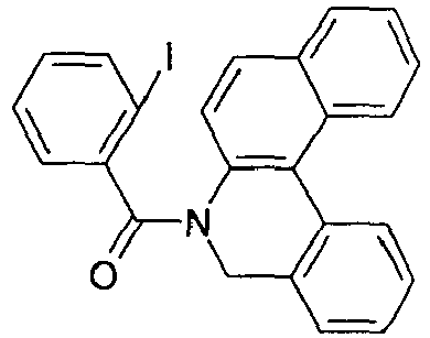
87% [609-67-6] [928307-79-3] 2c 
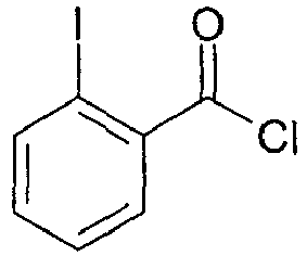

91 % [342404-76-6] [609-67-6 ] 2d 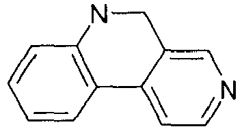


90% [61686-63-3] [609-67-6 ] 2e 


87% [1261446-07-4] 2f 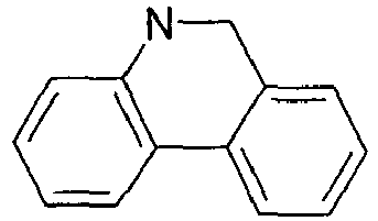


78% [1367346-08-4] 2g 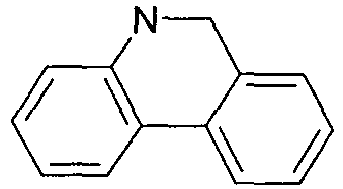


76% [75427-00-8] 2h 


77% [75427-00-8] 2j 


73% [609-67-6 ] -

- 9.7 g (243 mmol) NaH 60%ig in Mineralöl werden in 500 mL Dimethylformamid unter Schutzgasatmosphäre gelöst. 43.9 g (243 mmol) 5,6-Dihydrophenanthridin werden in 500 mL DMF gelöst und zu der Reaktionsmischung zugetropft. Nach 1 h bei Raumtemperatur wird eine Lösung von 60.6 g (242 mmol) 2-Brombenzylbromid in 500 mL DMF zugetropft. Das Reaktionsgemisch wird dann 1 h bei Raumtemperatur gerührt. Nach dieser Zeit wird das Reaktionsgemisch auf Eis gegossen und dreimal mit Dichlormethan extrahiert. Die vereinigten organischen Phasen werden über Na2SO4 getrocknet und eingeengt. Der Rückstand wird mit Toluol heiß extrahiert und aus Toluol / n-Heptan umkristallisiert. Die Ausbeute beträgt 62 g (75 %).
- Analog werden folgende Verbindungen erhalten:
Bsp. Edukt 1 Edukt 2 Produkt Ausbeute 3a 


83% [135689-85-9] 3b 


90% [172976-02-2 ] 3c 


95% [1396865-04-5] -

- 35 g (158 mmol) 5-(2-Brom-benzyl)-5H-phenanthridin-6-on werden in 1000 mL Dimethylformamid unter Schutzgasatmosphäre gelöst. Zu dieser Lösung werden 75.7 g (234 mmol) Tetrabutylammoniumbromid, 2.15 g (9.5 mmol) Palladiumacetat und 10 g (102 mmol) Kaliumacetat zugegeben. Anschließend wird das Gemisch bei 130 °C 2 h gerührt. Nach dieser Zeit wird das Reaktionsgemisch auf Raumtemperatur gekühlt. Der Rückstand wird abgesaugt und mit EtOH gewaschen. Der Rückstand wird aus n-Heptan/Toluol umkristallisiert. Die Ausbeute beträgt 17.7 g (74 %).
- Analog werden folgende Verbindungen erhalten:
Bsp. Edukt 1 Produkt Ausbeute 4a 

80% 4b 

83 % 4c 

67 % 4d 

73% 4e 

79% 4f 

82% 4g 

77% 4h 

78% 4j 

73% -

- 55.3 g (158 mmol) 5-(2-Brom-benzyl)-5,6-dihydrophenanthridin werden in 500 mL Dimethylformamid unter Schutzgasatmosphäre gelöst. Zu dieser Lösung werden 17.3 g (75 mmol) Benzyltrimethylammoniumbromid und 31.28 g (226 mmol) Kaliumcarbonat werden zugegeben. Anschließend wird unter Schutzgas 5.08 g (22 mmol) Pd(OAC)2 zugegeben, und das Gemisch wird bei 120 °C 9 h gerührt. Nach dieser Zeit wird das Reaktionsgemisch auf Raumtemperatur gekühlt und mit Dichlormethan extrahiert. Die vereinigten organischen Phasen werden über Na2SO4 getrocknet und eingeengt. Der Rückstand wird aus n-Heptan umkristallisiert. Die Ausbeute beträgt 34 g (81 %).
- Analog werden folgende Verbindunaen erhalten:
Bsp. Edukt 1 Produkt Ausbeute 5a 

82% 5b 

80% 5c 
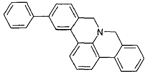
74% -

- 32 g (115 mmol) 9H-8a-Aza-benzo[fg]naphthacen-8-on werden in 1500 mL Aceton gelöst. Zu dieser Lösung werden 54.7 g (346 mmol) Kaliumpermanganat portionsweise werden zugegeben und zwei Tage bei Raumtemperatur gerührt. Nach dieser Zeit wird das restliche Kaliumpermanganat abfiltiert, die Lösung eingeengt und chromatographisch gereinigt (Laufmittel: Heptan/Dichloromethan, 5:1). Der Rückstand wird aus n-Heptan umkristallisiert. Die Ausbeute beträgt 24 g (73 %).
- Analoa werden folgende Verbindungen erhalten:
Bsp. Edukt 1 Produkt Ausbeute 6a 

60% 6b 

69% 6c 

71% 6d 

65% 6e 
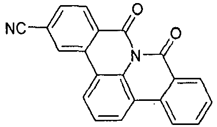
72% 6f 

77% 6g 

62% 6h 

65% 6j 

64% - Analog werden folgende Verbindungen mit 6 eg. KMnO4 erhalten:
Bsp. Edukt 1 Produkt Ausbeute 6i 

83% 6k 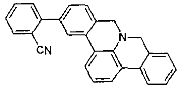

86% 6l 

. 79% 6m 

70% -
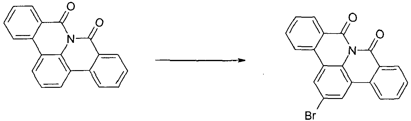
- 18.6 g (62,5mmol) 8a-Aza-benzo[fg]naphthacen-8,9-dion werden in 1800 mL CH2Cl2 vorgelegt. Anschließend gibt man 25.6 (312 mmol) Natriumacetat und 24.9 g (156 mmol) Brom zur Reaktionsmischung und rührt das Gemisch bei 80 °C für 30 h. Anschließend wird die Mischung mit 150 mL Wasser und 60 g NaOH-Plätzchen versetzt und der ausgefallene Feststoff abgesaugt. Das Produkt wird mit EtOH gewaschen und getrocknet. Ausbeute: 19 g (51 mmol), 81 % d. Th., Reinheit nach 1H-NMR ca. 96 %.
- Analoa werden folgende Verbindunaen erhalten:
Bsp. Edukt 1 Produkt Ausbeute 7a 

83 % 7b 

82 % 7c 

80% 7d 

78 % 7e 

34% 7f 

50% 7h 

70% 7j 
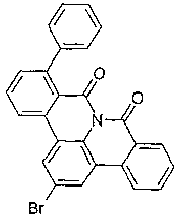
30% 7i 

42% 7k 

82% 7l 

85% 7m 
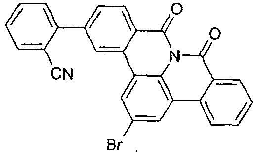
86% 7n 

67% 7o 

65% -

- 41.3 g (110.0 mmol) 4-dibenzofuranboronsäure, 38 g (110.0 mmol) 2-Brom-8a-aza-benzo[fg]naphthacen-8,9-dion und 44.6 g (210.0 mmol) Trikaliumphosphat werden in 500 mL Toulol, 500 mL Dioxan und 500 mL Wasser suspendiert. Zu dieser Suspension werden 913 mg (3.0 mmol) Trio-tolylphosphin und dann 112 mg (0.5 mmol) Palladium(II)acetat gegeben, und die Reaktionsmischung wird 16 h unter Rückfluss erhitzt. Nach Erkalten wird die organische Phase abgetrennt, über Kieselgel filtriert, dreimal mit 200 mL Wasser gewaschen und anschließend zur Trockene eingeengt. Der Rückstand wird aus Toluol und aus Dichlormethan / isoPropanol umkristallisiert und abschließend im Hochvakuum sublimiert, Reinheit beträgt 99.9 %. Die Ausbeute beträgt 40 g (88 mmol), entsprechend 80% der Theorie.
- Analog werden folgende Verbindungen erhalten:
Bsp. Edukt 1 Edukt 2 Produkt Ausbeute. 8a 


82% 236389-21-2 8b 

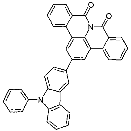
81% [854952-58-2] 8c 


84% [943836-24-6] 8e 


88% [128388-54-5] 8f 


67% [1338488-91-7] 8g 


75% [1001911-63-2] 8h 


76% [854952-60-6] 8j 


83% [1313018-07-3] 8i 


85% [128388-54-5] 8k 


80% 81 


89% [128388-54-5] 8m 


88% [1314019-67-4] 8n 


86% [854952-58-2] 8o 


82% [854952-58-2] 8p 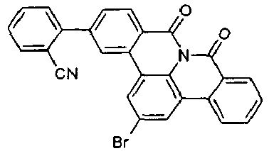


86% [128388-54-5] 8q 

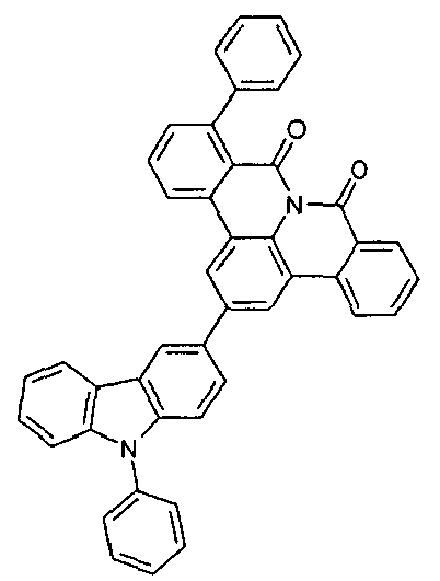
87% [854952-58-2] 8r 


81% [854952-58-2] 8s 
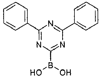

79% [1251825-65-6] 8t 

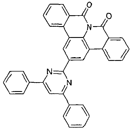
86% [1314221-56-1] 8u 


87% [128388-54-5] 8v 


80% [128388-54-5] 8w 


81% 236389-21-2 8y 


83% 236389-21-2 8z 


84% 236389-21-2 - Analog werden folgende Verbindungen mit 0.5 eq. Brom erhalten:
Bsp. Edukt 1 Edukt 2 Produkt Ausbeute 8w 


86% [4612-26-4] 8y 


81% [1135916-40-3] -

- 32 g (102-4 mmol) 3,6-Diphenyl-9H-carbazol, 42 g (112 mmol) 2-Brom-8a-aza-benzo[fg]naphthacen-8,9-dion und 2.3 (10-2 mmol)1,3-Di[2-pyridyl]-1,3-propandion, 28.3 g (204 mmol) Kaliumcarbonat und 1.9 g (10.2 mmol) Kupferiodid werden im 1000 ml DMF unter Rückfluss 90 h gerührt. Die Lösung wird mit Wasser verdünnt und mit Essigester zweimal extrahiert, die vereinigten organischen Phasen über Na2SO4 getrocknet und einrotiert und chromatographisch (EtOAc/Hexan: 2/3) gereinigt. Der Rückstand wird aus Toluol und aus Dichlormethan umkristallisiert und abschließend im Hochvakuum sublimiert, Reinheit beträgt 99.9 %. Die Ausbeute beträgt 46 g (75 mmol), entsprechend 68 % der Theorie.
- Analog werden folgende Verbindungen erhalten:
Bsp. Edukt 1 Edukt 2 Produkt Ausbeute 9a 


65% [1257220-47-5] -
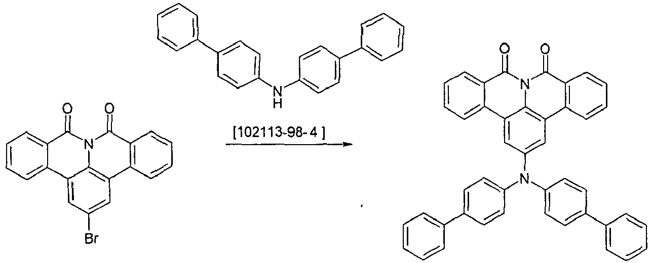
- Unter Schutzgas werden 24.5 g (79.8 mmol) Bis-biphenyl-4-yl-amin, 32.7 g (87 mmol) 2-Brom-8a-aza-benzo[fg]naphthacen-8,9-dion, 15.9 ml (15.9 mmol) 1 mol/L Tri-tert-butylphosphin und 1.79 g (7.9 mmol) Palladiumacetat in 120 ml p-Xylol suspendiert. Die Reaktionsmischung wird 16 h unter Rückfluss erhitzt. Nach Erkalten wird die organische Phase abgetrennt, dreimal mit 200 mL Wasser gewaschen und anschließend zur Trockene eingeengt. Der Rückstand wird mit Toluol heiß extrahiert, aus Toluol umkristallisiert und abschließend im Hochvakuum sublimiert. Die Reinheit beträgt 99.9%, Ausbeute 44 g (72 mmol), 83 % der Theorie.
- Analog werden folgende Verbindunaen erhalten:
Bsp. Edukt 1 Edukt 2 Produkt Ausbeute 10a 

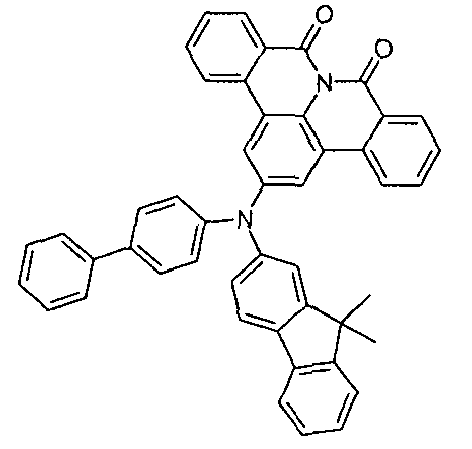
85% 10b 


76% -

- 1-Phenyl-1,3-dihydro-benzoimidazol-2-on 52g (250 mmol) und 38 g (275 mmol) K2CO3 werden in 100 ml DMF vorgelegt. Nach 1 h bei Raumtemperatur wird eine Lösung von 62 g (250 mmol) 2-Brombenzylbromid in 500 mL DMF zugetropft. Das Reaktionsgemisch wird dann 25 h bei Raumtemperatur gerührt. Nach dieser Zeit wird das Reaktionsgemisch auf Eis gegossen und dreimal mit Dichlormethan extrahiert. Die vereinigten organischen Phasen werden über Na2SO4 getrocknet und eingeengt. Der Rückstand wird mit Toluol heiß extrahiert und aus Toluol / n-Heptan umkristallisiert. Die Ausbeute beträgt 65 g (70 %).
- Analog werden folgende Verbindungen erhalten:
Bsp. Edukt 1 Edukt 2 Produkt Ausbeute 11a 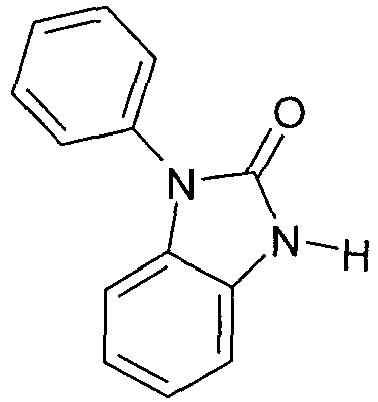


76% 172976-02-2 [1225484-71-8] 11b 


71% [30017-73-3] - Analog werden folgende Verbindungen mit 125 mmol 1,3-Dihydro-2H-benzimidazol-2-on [615-16-7] erhalten:
Bsp. Edukt 1 Edukt 2 Produkt Ausbeute. 11c 


86% [615-16-7 ] [1396865-04-5 ] 11d 


82% [615-16-7 ] [3433-80-5 ] - Die Cyclisierung erfolgt analog Beispiel 5:
Bsp. Edukt 1 Produkt Ausbeute 5d 

62% 5e 

63% 5f 
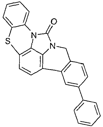
74% 5h 

66% 5j 

64% - Die Weiteroxidation erfolgt analog Beispiel 6:
Bsp. Edukt 1 Produkt Ausbeute 6n 

60% 6o 

69% 6p 

71% 6q 

70% 6r 

67% - Die Bromierung erfolgt analog Beispiel 7:
Bsp. Edukt 1 Produkt Ausbeute 7n 

60% 7o 

69% 7p 

71% 7q 

70% 7r 

67% - Über Ullmann-Reaktion analog zu Beispiel 9 werden folgende Verbindungen hergestellt:
Bsp. Edukt 1 Edukt 2 Produkt Ausbeute 9b 


64% [1257220-47-5] 9c 
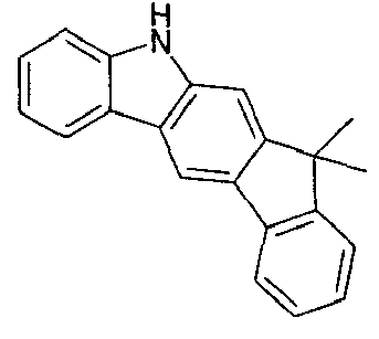

63% [1257220-47-5] 9d 


65% [1257220-47-5] 9e 


66% [1257220-47-5] 9f 


71% [56525-79-2] - In den folgenden Beispielen E1 bis E27 (siehe Tabellen 1 und 2) werden die Daten verschiedener OLEDs vorgestellt. Glasplättchen, die mit strukturiertem ITO (Indium Zinn Oxid) der Dicke 50 nm beschichtet sind werden zur verbesserten Prozessierung mit 20 nm PEDOT:PSS beschichtet (Poly(3,4-ethylenedioxythiophen)poly(styrolsulfonat), bezogen als CLEVIOS™ P VP AI 4083 von Heraeus Precious Metals GmbH Deutschland, aus wässriger Lösung aufgeschleudert). Diese beschichteten Glasplättchen bilden die Substrate, auf welche die OLEDs aufgebracht werden. Die OLEDs haben prinzipiell folgenden Schichtaufbau: Substrat / Lochtransportschicht (HTL) / Zwischenschicht (IL) / Elektronenblockierschicht (EBL) / Emissionsschicht (EML) / optionale Lochblockierschicht (HBL) / Elektronentransportschicht (ETL) / optionale Elektroneninjektionsschicht (EIL) und abschließend eine Kathode. Die Kathode wird durch eine 100 nm dicke Aluminiumschicht gebildet. Der genaue Aufbau der OLEDs ist Tabelle 1 zu entnehmen. Die zur Herstellung der OLEDs benötigten Materialien sind in Tabelle 3 gezeigt. Eine Bezeichnung wie "8a" bezieht sich hierbei auf die entsprechende Verbindung aus dem oben genannten Beispiel 8a. Dies gilt analog für alle verwendeten erfindungsgemäßen Materialien.
- Alle Materialien werden in einer Vakuumkammer thermisch aufgedampft. Dabei besteht die Emissionsschicht immer aus mindestens einem Matrixmaterial (Hostmaterial, Wirtsmaterial) und einem emittierenden Dotierstoff (Dotand, Emitter), der dem Matrixmaterial bzw. den Matrixmaterialien durch Coverdampfung in einem bestimmten Volumenanteil beigemischt wird. Eine Angabe wie IC1:8c:TER1 (55%:35%:10%) bedeutet hierbei, dass das Material IC1 in einem Volumenanteil von 55%, 8c in einem Anteil von 35% und TER1 in einem Anteil von 10% in der Schicht vorliegt. Analog kann auch die Elektronentransportschicht aus einer Mischung von zwei Materialien bestehen.
- Die OLEDs werden standardmäßig charakterisiert. Hierfür werden die Elektrolumineszenzspektren, die Stromeffizienz (gemessen in cd/A), die Leistungseffizienz (gemessen in lm/W) und die externe Quanteneffizienz (EQE, gemessen in Prozent) in Abhängigkeit der Leuchtdichte, berechnet aus Strom-Spannungs-Leuchtdichte-Kennlinien (IUL-Kennlinien) unter Annahme einer lambertschen Abstrahlcharakteristik sowie die Lebensdauer bestimmt. Die Elektrolumineszenzspektren werden bei einer Leuchtdichte von 1000 cd/m2 bestimmt und daraus die CIE 1931 x und y Farbkoordinaten berechnet. Die Angabe U1000 in Tabelle 2 bezeichnet die Spannung, die für eine Leuchtdichte von 1000 cd/m2 benötigt wird. SE1000 und LE1000 bezeichnen die Strom- bzw. Leistungseffizienz, die bei 1000 cd/m2 erreicht werden. EQE1000 schließlich bezeichnet die externe Quanteneffizienz bei einer Betriebsleuchtdichte von 1000 cd/m2. Als Lebensdauer LD wird die Zeit definiert, nach der die Leuchtdichte bei Betrieb mit konstantem Strom von der Startleuchtdichte auf einen gewissen Anteil L1 absinkt. Eine Angabe von L0;j0 = 4000 cd/m2 und L1 = 80% in Tabelle 2 bedeutet, dass die in Spalte LD angegebene Lebensdauer der Zeit entspricht, nach der die Anfangsleuchtdichte von 4000 cd/m2 auf 3200 cd/m2 absinkt. Analog bedeutet L0;j0 = 20 mA/cm2, L1 = 70%, dass die Leuchtdichte bei Betrieb mit 20 mA/cm2 nach der Zeit LD auf 70% ihres Anfangswertes absinkt.
- Die Daten der verschiedenen OLEDs sind in Tabelle 2 zusammengefasst. Man erhält bei Einsatz der erfindungsgemäßen Verbindungen sowohl bei Verwendung als Elektronentransportmaterial (Beispiele E1, E2, E13, E17, E18) als auch Matrixmaterial für phopshoreszierende Emitter (restliche Beispiele) sehr gute Werte für Effizienz, Spannung und Lebensdauer. Dies gilt beim Einsatz als Einzelmatrix sowie in Mixed-Matrix Systemen in Kombination mit unterschiedlichen Materialien wie IC1, IC2, Cbz1. Insbesondere sind die hervorragenden Spannungen und damit Leistungseffizienzen bei gleichtzeitig sehr guter Lebensdauer hervorzuheben (siehe z. B. E10).
Tabelle 1: Aufbau der OLEDs Bsp. HTL Dicke IL Dicke EBL Dicke EML Dicke HBL Dicke ETL Dicke EIL Dicke E1 SpA1 140nm HATCN 5nm SpMA1 20nm M1:D1 (95%:5%) 20nm --- 8k 30nm LiQ 3nm E2 SpA1 140nm HATCN 5nm SpMA1 20nm M1:D1 (95%:5%) 20nm --- 8s:LiQ (50%:50%) 30nm --- E3 SpA1 70nm HATCN 5nm SpMA1 90nm IC1:TEG1 (90%:10%) 30nm --- 8s:LiQ (50%:50%) 40nm --- E4 SpA1 70nm HATCN 5nm SpMA1 90nm 8:TEG1 (90%:10%) 30nm --- ST1:LiQ (50%:50%) 40nm --- E5 SpA1 90nm HATCN 5nm SpMA1 130nm 8a:TER1 (92%:8%) 40nm --- ST1:LiQ (50%:50%) 40nm --- E6 SpA1 70nm HATCN 5nm SpMA1 90nm 8b:TEG1 (90%:10%) 30nm --- ST1:LiQ (50%:50%) 40nm --- E7 SpA1 90nm HATCN 5nm SpMA1 130nm 8b:TER1 (92%:8%) 40nm --- ST1:LiQ (50%:50%) 40nm --- E8 SpA1 90nm HATCN 5nm SpMA1 130nm IC1:8c:TER1 (55%:35%:10%) 40nm IC1 5nm ST1:LiQ (50%:50%) 35nm --- E9 SpA1 70nm HATCN 5nm SpMA1 90nm 8e:TEG1 (90%:10%) 30nm --- ST1:LiQ (50%:50%) 40nm --- E10 SpA1 70nm HATCN 5nm SpMA1 90nm 8e:IC2:TEG1 (45%:45%:10%) 40nm --- ST1:LiQ (50%:50%) 30nm --- E11 SpA1 70nm HATCN 5nm SpMA1 90nm 8e:Cbz1:TEG1 (60%:35%:5%) 30nm IC1 10nm ST1:LiQ (50%:50%) 30nm --- E12 SpA1 70nm HATCN 5nm SpMA1 90nm 8k:TEG1 (90%:10%) 30nm --- ST1:LiQ (50%:50%) 40nm --- E13 SpA1 70nm HATCN 5nm SpMA1 90nm IC1:TEG1 (90%:10%) 30nm --- 8o 40nm LiQ 3nm E14 SpA1 70nm HATCN 5nm SpMA1 90nm 8r:TEG1 (90%:10%) 30nm --- ST1:LiQ (50%:50%) 40nm --- E15 SpA1 70nm HATCN 5nm SpMA1 90nm 8s:TEG1 (90%:10%) 30nm --- ST1:LiQ (50%:50%) 40nm --- E16 SpA1 90nm HATCN 5nm SpMA1 130nm 8s:TER1 (92%:8%) 40nm --- ST1:LiQ (50%:50%) 40nm --- E17 SpA1 70nm HATCN 5nm SpMA1 90nm IC1:TEG1 (90%:10%) 30nm --- 8s 40nm LiF 1nm E18 SpA1 140nm HATCN 5nm SpMA1 20nm M1:D1 (95%:5%) 20nm --- 8v 30nm LiQ 3nm E19 SpA1 90nm HATCN 5nm SpMA1 130nm 8w:TER1 (92%:8%) 40nm --- ST1:LiQ (50%:50%) 40nm --- E20 SpA1 70nm HATCN 5nm SpMA1 90nm 8w:TEG1 (90%:10%) 30nm --- ST1:LiQ (50%:50%) 40nm --- E21 SpA1 90nm HATCN 5nm SpMA1 130nm 8y:TER1 (92%:8%) 40nm --- ST1:LiQ (50%:50%) 40nm --- E22 SpA1 90nm HATCN 5nm SpMA1 130nm 9:TER1 (92%:8%) 40nm --- ST1:LiQ (50%:50%) 40nm --- E23 SpA1 90nm HATCN 5nm SpMA1 130nm 9a:TER1 (92%:8%) 40nm --- ST1:LiQ (50%:50%) 40nm --- E24 SpA1 70nm HATCN 5nm SpMA1 90nm 9b:TEG1 (90%:10%) 30nm --- ST1:LiQ (50%:50%) 40nm --- E25 SpA1 70nm HATCN 5nm SpMA1 90nm 9c:TEG1 (90%:10%) 30nm --- ST1:LiQ (50%:50%) 40nm --- E26 SpA1 90nm HATCN 5nm SpMA1 130nm 9f:TER1 (92%:8%) 40nm --- ST1:LiQ (50%:50%) 40nm --- E27 SpA1 90nm HATCN 5nm SpMA1 130nm IC2:10:TER1 (70%:20%:10%) 40nm IC1 5nm ST1:LiQ (50%:50%) 35nm --- Tabelle 2: Daten der OLEDs Bsp. U1000 (V) SE1000 (cd/A) LE1000 (lm/W) EQE 1000 CIE x/y bei 1000 cd/M 1 L0;j0 L1 % LD (h) E1 4.7 8.1 5.4 7.2% 0.13/0.14 60mA/cm2 70 200 E2 4.5 8.5 5.9 7.3% 0.13/0.14 60mA/cm2 70 225 E3 3.4 61 57 16.7% 0.33/0.62 20mA/cm2 70 220 E4 3.3 56 53 15.3% 0.32/0.62 20mA/cm2 70 240 E5 4.4 12.2 8.6 13.2% 0.67/0.33 4000 cd/m2 80 360 E6 3.5 54 48 14.7% 0.33/0.63 20mA/cm2 70 195 E7 4.6 11.0 7.5 11.9% 0.67/0.33 4000 cd/m2 80 345 E8 4.1 12.6 9.6 13.6% 0.67/0.33 4000 cd/m2 80 490 E9 3.0 54 57 14.8% 0.32/0.62 20mA/cm2 70 260 E10 3.0 61 65 16.7% 0.34/0.63 20mA/cm2 80 310 E11 3.3 63 61 17.4% 0.32/0.62 20mA/cm2 80 265 E12 3.4 52 48 14.4% 0.33/0.61 20mA/cm2 80 180 E13 3.6 57 50 15.6% 0.32/0.62 10000 cd/m2 70 220 E14 3.2 55 54 15.0% 0.32/0.62 20mA/cm2 70 230 E15 3.3 54 51 14.7% 0.33/0.61 20mA/cm2 80 145 E16 4.6 10.6 7.3 11.4% 0.67/0.33 4000 cd/m2 80 310 E17 3.4 59 55 16.1% 0.33/0.62 20mA/cm2 70 245 E18 4.9 7.0 4.9 6.7% 0.13/0.14 60mA/cm2 70 230 E19 3.1 56 56 15.5% 0.34/0.61 20mA/cm2 80 160 E20 3.8 10.1 8.4 10.9% 0.67/0.33 4000 cd/m2 80 385 E21 4.5 12 8.4 13.0% 0.67/0.33 4000 cd/m2 80 405 E22 4.8 11 7.2 11.9% 0.67/0.33 4000 cd/m2 80 370 E23 4.3 12.8 9.3 13.8% 0.67/0.33 4000 cd/m2 80 420 E24 3.0 61 63 17.0% 0.33/0.62 20mA/cm2 80 165 E25 3.2 59 58 16.4% 0.32/0.62 20mA/cm2 80 150 E26 4.6 11.1 7.6 12.0% 0.67/0.33 4000 cd/m2 80 405 E27 4.3 12.2 8.9 13.2% 0.67/0.33 4000 cd/m2 80 520 Tabelle 3: Strukturformeln der Materialien für die OLEDs 

HATCN SpA1 

M1 D1 

ST1 LiQ 

TER1 TEG1 

IC1 IC2 

SpMA1 Cbz1

Claims (14)
- Verbindung gemäß Formel (1),
 X ist bei jedem Auftreten gleich oder verschieden CR oder N; oder zwei benachbarte Gruppen X stehen zusammen für eine Gruppe, ausgewählt aus NR, O oder S, so dass ein Fünfring entsteht;Y ist bei jedem Auftreten gleich oder verschieden Z=Z, NR, wobei R ungleich H ist, O oder S;Z ist bei jedem Auftreten gleich oder verschieden CR oder N oder die benachbarten Gruppen Z=Z stehen zusammen für eine Gruppe der Formel (2),
 L ist für n = 1 nicht vorhanden und ist für n = 2 eine Einfachbindung oder eine bivalente Gruppe und für n = 3 eine trivalente Gruppe und für n = 4 eine tetravalente Gruppe und für n = 5 eine pentavalente Gruppe und für n = 6 eine hexavalente Gruppe; dabei ist L statt einer Gruppe R an einer beliebigen Stelle des Grundgerüsts gebunden;R ist bei jedem Auftreten gleich oder verschieden ausgewählt aus der Gruppe bestehend aus H, D, F, Cl, Br, I, CN, NO2, N(Ar1)2, N(R1)2, C(=O)Ar1, C(=O)R1, P(=O)(Ar1)2, einer geradkettigen Alkyl-, Alkoxy- oder Thioalkylgruppe mit 1 bis 40 C-Atomen oder einer verzweigten oder cyclischen Alkyl-, Alkoxy- oder Thioalkylgruppe mit 3 bis 40 C-Atomen oder einer Alkenyl- oder Alkinylgruppe mit 2 bis 40 C-Atomen, die jeweils mit einem oder mehreren Resten R1 substituiert sein kann, wobei eine oder mehrere nicht-benachbarte CH2-Gruppen durch R1C=CR1, C=C, Si(R1)2, C=O, C=S, C=NR1, P(=O)(R1), SO, SO2, NR1, O, S oder CONR1 ersetzt sein können und wobei ein oder mehrere H-Atome durch D, F, Cl, Br, I, CN oder NO2 ersetzt sein können, einem aromatischen oder heteroaromatischen Ringsystem mit 5 bis 60 aromatischen Ringatomen, das jeweils mit einem oder mehreren Resten R1 substituiert sein kann, einer Aryloxy- oder Heteroaryloxygruppe mit 5 bis 60 aromatischen Ringatomen, die mit einem oder mehreren Resten R1 substituiert sein kann, einer Aralkyl- oder Heteroaralkylgruppe mit 5 bis 60 aromatischen Ringatomen, die mit einem oder mehreren Resten R1 substituiert sein kann, oder einer Kombination dieser Systeme, wobei optional zwei oder mehr benachbarte Substituenten R ein monocyclisches oder polycyclisches, aliphatisches, aromatisches oder heteroaromatisches Ringsystem bilden können, das mit einem oder mehreren Resten R1 substituiert sein kann;Ar1 ist bei jedem Auftreten gleich oder verschieden ein aromatisches oder heteroaromatisches Ringsystem mit 5-30 aromatischen Ringatomen, das mit einem oder mehreren nicht-aromatischen Resten R1 substituiert sein kann; dabei können zwei Reste Ar1, welche an dasselbe N-Atom oder P-Atom binden, auch durch eine Einfachbindung oder eine Brücke, ausgewählt aus N(R1), C(R1)2 oder O, miteinander verbrückt sein;R1 ist ausgewählt aus der Gruppe bestehend aus H, D, F, CN, einem aliphatischem Kohlenwasserstoffrest mit 1 bis 20 C-Atomen, einem aromatischem oder heteroaromatischem Ringsystem mit 5 bis 30 aromatischen Ringatomen, in dem ein oder mehrere H-Atome durch D, F, Cl, Br, I, CN oder eine Alkylgruppe mit 1 bis 10 C-Atomen oder eine Alkenylgruppe mit 2 bis 10 C-Atomen ersetzt sein können, wobei zwei oder mehr benachbarte Substituenten R1 miteinander ein mono- oder polycyclisches, aliphatisches, aromatisches oder heteroaromatisches Ringsystem bilden können;n ist 1, 2, 3, 4, 5 oder 6;wobei die folgende Verbindung von der Erfindung ausgenommen ist:
- Verbindung nach Anspruch 1, ausgewählt aus den Verbindungen der Formel (5) und Formel (9),

- Verbindung nach Anspruch 1 oder 2, ausgewählt aus den Verbindungen der Formel (6),

- Verbindung nach einem oder mehreren der Ansprüche 1 bis 3, ausgewählt aus den Verbindungen der Formeln (7), (8), (10) und (11),


- Verbindung nach einem oder mehreren der Ansprüche 1 bis 4, ausgewählt aus den Verbindungen der Formeln (7a), (8a), (10a) und (11a),
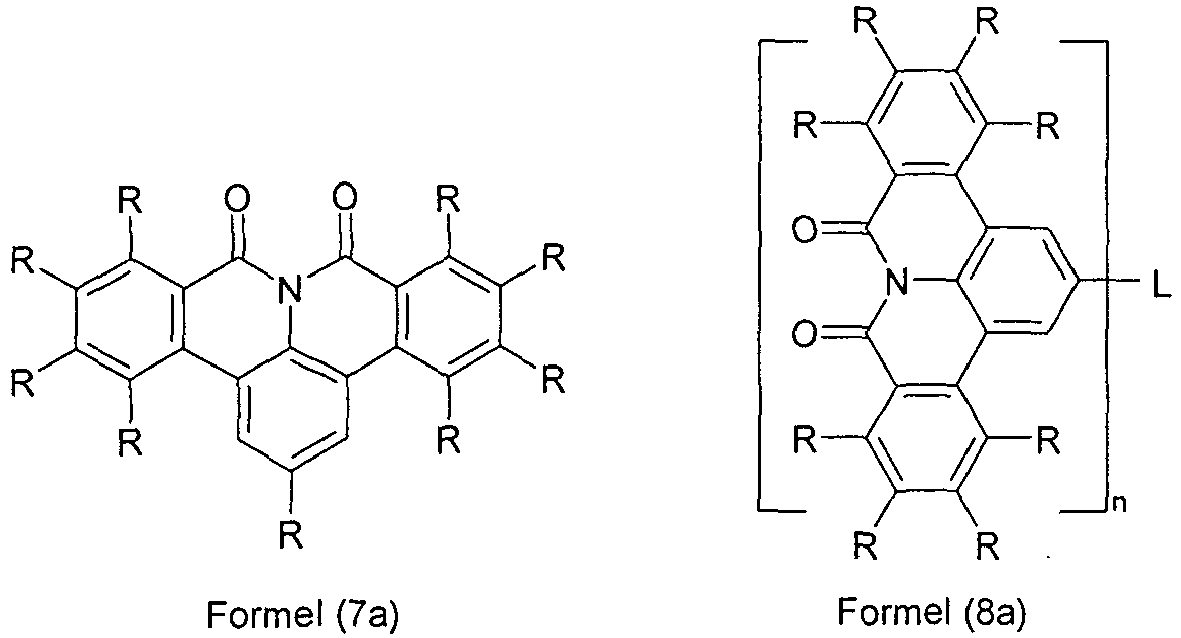

- Verbindung nach einem oder mehreren der Ansprüche 1 bis 5, ausgewählt aus den Verbindungen der Formeln (7c), (8c), (10c) und (11 c),


- Verbindung nach einem oder mehreren der Ansprüche 1 bis 3, ausgewählt aus den Verbindungen der Formel (12),

- Verbindung nach einem oder mehreren der Ansprüche 1 bis 7, dadurch gekennzeichnet, dass L für n = 2 ausgewählt ist aus einer Einfachbindung, CR2, O, NR oder C(=O) oder für n = 3 für N steht oder für n ≥ 2 ausgewählt ist aus einem aromatischen oder heteroaromatischen Ringsystem mit 5 bis 24 aromatischen Ringatomen, das mit einem oder mehreren Resten R substituiert sein kann.
- Verbindung nach einem oder mehreren der Ansprüche 1 bis 8, dadurch gekennzeichnet, dass mindestens ein Rest R ausgewählt ist aus der Gruppe bestehend aus einem aromatischen oder heteroaromatischen Ringsystem mit 5 bis 24 aromatischen Ringatomen, welches durch einen oder mehrere Reste R1 substituiert sein kann, und/oder dass mindestens ein Rest R ausgewählt ist aus -C(=O)Ar1 oder -P(=O)(Ar1)2 und/oder dass mindestens ein Rest R ausgewählt ist aus Triaryl- bzw. Heteroarylaminderivaten und/oder mindestens ein Substituent R steht für -N(Ar1)2
- Verbindung nach einem oder mehreren der Ansprüche 1 bis 9, dadurch gekennzeichnet, dass mindestens eine Gruppe R ausgewählt ist aus der Gruppe bestehend aus Benzol, Biphenyl, Terphenyl, Quaterphenyl, Fluoren, Spirobifluoren, Naphthalin, Pyrrol, Furan, Thiophen, Indol, Benzofuran, Benzothiophen, Carbazol, Dibenzothiophen, Dibenzofuran, 1,3,5-Triazin, Pyridin, Pyrimidin, Pyrazin, Pyridazin, Indenocarbazol, verbrücktes Carbazol, Indolocarbazol, Anthracen, Phenanthren, Pyren, Triphenylen, Benzanthracen, Chinolin, Isochinolin, Phenanthridin, Phenanthrolin, Azacarbazol, Imidazol, Pyrazol, Thiazol, Oxazol, Oxadiazol, Triazol, Benzimidazol oder Kombinationen aus zwei, drei oder vier dieser Gruppen, wobei die Gruppen jeweils durch einen oder mehrere Reste R1 substituiert sein können.
- Formulierung, enthaltend mindestens eine Verbindung nach einem oder mehreren der Ansprüche 1 bis 10 und mindestens eine weitere Verbindung, insbesondere ein organisches Lösemittel.
- Verwendung einer Verbindung nach einem oder mehreren der Ansprüche 1 bis 10 in einer elektronischen Vorrichtung.
- Elektronische Vorrichtung, enthaltend mindestens eine Verbindung nach einem oder mehreren der Ansprüche 1 bis 10, insbesondere ausgewählt aus der Gruppe bestehend aus organischen Elektrolumineszenzvorrichtungen, organischen integrierten Schaltungen, organischen Feld-Effekt-Transistoren, organischen Dünnfilmtransistoren, organischen lichtemittierenden Transistoren, organischen Solarzellen, organischen farbstoffsensibilisierten Solarzellen, organischen optischen Detektoren, organischen Photorezeptoren, organischen Feld-Quench-Devices, lichtemittierenden elektrochemischen Zellen, organischen Laserdioden und Organic Plasmon Emitting Devices.
- Elektronische Vorrichtung nach Anspruch 13, wobei es sich um eine organische Elektrolumineszenzvorrichtung handelt, dadurch gekennzeichnet, dass die Verbindung nach einem oder mehreren der Ansprüche 1 bis 10 als Matrixmaterial für einen fluoreszierenden oder phosphoreszierenden Emitter und/oder in einer Lochblockierschicht und/oder in einer Elektronentransportschicht eingesetzt wird.
Priority Applications (1)
| Application Number | Priority Date | Filing Date | Title |
|---|---|---|---|
| EP13762409.4A EP2906661B1 (de) | 2012-10-11 | 2013-09-13 | Materialien für organische elektrolumineszenzvorrichtungen |
Applications Claiming Priority (3)
| Application Number | Priority Date | Filing Date | Title |
|---|---|---|---|
| EP12007040 | 2012-10-11 | ||
| PCT/EP2013/002748 WO2014056567A1 (de) | 2012-10-11 | 2013-09-13 | Materialien für organische elektrolumineszenzvorrichtungen |
| EP13762409.4A EP2906661B1 (de) | 2012-10-11 | 2013-09-13 | Materialien für organische elektrolumineszenzvorrichtungen |
Publications (2)
| Publication Number | Publication Date |
|---|---|
| EP2906661A1 EP2906661A1 (de) | 2015-08-19 |
| EP2906661B1 true EP2906661B1 (de) | 2016-10-26 |
Family
ID=47076015
Family Applications (1)
| Application Number | Title | Priority Date | Filing Date |
|---|---|---|---|
| EP13762409.4A Active EP2906661B1 (de) | 2012-10-11 | 2013-09-13 | Materialien für organische elektrolumineszenzvorrichtungen |
Country Status (4)
| Country | Link |
|---|---|
| US (1) | US9741942B2 (de) |
| EP (1) | EP2906661B1 (de) |
| JP (1) | JP6250684B2 (de) |
| WO (1) | WO2014056567A1 (de) |
Cited By (1)
| Publication number | Priority date | Publication date | Assignee | Title |
|---|---|---|---|---|
| CN107216331A (zh) * | 2017-07-07 | 2017-09-29 | 华南理工大学 | 一种四氢萘啶并四氢喹唑啉衍生物及其合成方法和应用 |
Families Citing this family (13)
| Publication number | Priority date | Publication date | Assignee | Title |
|---|---|---|---|---|
| CN116655603A (zh) | 2014-07-21 | 2023-08-29 | 默克专利有限公司 | 用于电子器件的材料 |
| US10683453B2 (en) | 2014-12-12 | 2020-06-16 | Merck Patent Gmbh | Organic compounds with soluble groups |
| WO2016124304A1 (de) | 2015-02-03 | 2016-08-11 | Merck Patent Gmbh | Metallkomplexe |
| US10249831B2 (en) | 2015-02-09 | 2019-04-02 | Merck Patent Gmbh | Electronic device containing cyclic lactams |
| US10074815B2 (en) * | 2015-03-31 | 2018-09-11 | The Regents Of The University Of Michigan | Organic electroluminescent devices |
| JP7214633B2 (ja) | 2016-11-09 | 2023-01-30 | メルク パテント ゲーエムベーハー | 有機エレクトロルミネッセントデバイス用材料 |
| WO2018099846A1 (de) * | 2016-11-30 | 2018-06-07 | Merck Patent Gmbh | Verbindungen mit valerolaktam-strukturen |
| US11466021B2 (en) | 2016-12-05 | 2022-10-11 | Merck Patent Gmbh | Materials for organic electroluminescent devices |
| EP3551636A4 (de) * | 2016-12-06 | 2019-12-25 | Valorbec, Société en Commandite | Thienoisochinoline und deren derivate zur behandlung von krebs |
| TWI791481B (zh) * | 2017-01-30 | 2023-02-11 | 德商麥克專利有限公司 | 形成有機電致發光(el)元件之方法 |
| WO2020109434A1 (de) * | 2018-11-30 | 2020-06-04 | Merck Patent Gmbh | Verbindungen für elektronische vorrichtungen |
| KR20220066324A (ko) * | 2019-09-20 | 2022-05-24 | 메르크 파텐트 게엠베하 | 전자 디바이스용 재료 |
| CN116354882B (zh) * | 2021-12-28 | 2025-08-05 | 香港科技大学深圳研究院 | 具有菲啶酮结构的纯有机室温磷光材料及制备方法和应用 |
Family Cites Families (53)
| Publication number | Priority date | Publication date | Assignee | Title |
|---|---|---|---|---|
| IE49377B1 (en) | 1979-02-01 | 1985-10-02 | Lilly Co Eli | Process for preparation of beta-lactam compounds |
| PL136237B1 (en) | 1981-09-09 | 1986-02-28 | Pfizer Inc | Process for preparing novel derivatives of 6'-/2-amino-/4-acyloxyphenyl/acetamido/-penicillanoyloxymethyl penicillanate 1,1-dioxide |
| US4539507A (en) | 1983-03-25 | 1985-09-03 | Eastman Kodak Company | Organic electroluminescent devices having improved power conversion efficiencies |
| US5151629A (en) | 1991-08-01 | 1992-09-29 | Eastman Kodak Company | Blue emitting internal junction organic electroluminescent device (I) |
| JPH07133483A (ja) | 1993-11-09 | 1995-05-23 | Shinko Electric Ind Co Ltd | El素子用有機発光材料及びel素子 |
| EP0676461B1 (de) | 1994-04-07 | 2002-08-14 | Covion Organic Semiconductors GmbH | Spiroverbindungen und ihre Verwendung als Elektrolumineszenzmaterialien |
| DE19652261A1 (de) | 1996-12-16 | 1998-06-18 | Hoechst Ag | Arylsubstituierte Poly(p-arylenvinylene), Verfahren zur Herstellung und deren Verwendung in Elektroluminszenzbauelementen |
| TW591030B (en) * | 1997-03-10 | 2004-06-11 | Janssen Pharmaceutica Nv | Farnesyl transferase inhibiting 1,8-annelated quinolinone derivatives substituted with N- or C-linked imidazoles |
| EP1729327B2 (de) | 1999-05-13 | 2022-08-10 | The Trustees Of Princeton University | Verwendung einer phosphoreszierenden Iridiumverbindung als Emissionsmolekül in einer organischen lichtemittierenden Vorrichtung |
| EP1933395B2 (de) | 1999-12-01 | 2019-08-07 | The Trustees of Princeton University | Komplex der Formel L2IrX |
| US6660410B2 (en) | 2000-03-27 | 2003-12-09 | Idemitsu Kosan Co., Ltd. | Organic electroluminescence element |
| US20020121638A1 (en) | 2000-06-30 | 2002-09-05 | Vladimir Grushin | Electroluminescent iridium compounds with fluorinated phenylpyridines, phenylpyrimidines, and phenylquinolines and devices made with such compounds |
| EP1325671B1 (de) | 2000-08-11 | 2012-10-24 | The Trustees Of Princeton University | Organometallische verbdindungen und emissionsverschobene organische elektrolumineszens |
| JP4154138B2 (ja) | 2000-09-26 | 2008-09-24 | キヤノン株式会社 | 発光素子、表示装置及び金属配位化合物 |
| JP4154139B2 (ja) | 2000-09-26 | 2008-09-24 | キヤノン株式会社 | 発光素子 |
| JP4154140B2 (ja) | 2000-09-26 | 2008-09-24 | キヤノン株式会社 | 金属配位化合物 |
| ITRM20020411A1 (it) | 2002-08-01 | 2004-02-02 | Univ Roma La Sapienza | Derivati dello spirobifluorene, loro preparazione e loro uso. |
| JP4411851B2 (ja) | 2003-03-19 | 2010-02-10 | コニカミノルタホールディングス株式会社 | 有機エレクトロルミネッセンス素子 |
| EP1618170A2 (de) | 2003-04-15 | 2006-01-25 | Covion Organic Semiconductors GmbH | Mischungen von organischen zur emission befähigten halbleitern und matrixmaterialien, deren verwendung und elektronikbauteile enthaltend diese mischungen |
| JP4635870B2 (ja) | 2003-04-23 | 2011-02-23 | コニカミノルタホールディングス株式会社 | 有機エレクトロルミネッセンス素子、照明装置及び表示装置 |
| DE10333232A1 (de) | 2003-07-21 | 2007-10-11 | Merck Patent Gmbh | Organisches Elektrolumineszenzelement |
| DE10338550A1 (de) | 2003-08-19 | 2005-03-31 | Basf Ag | Übergangsmetallkomplexe mit Carbenliganden als Emitter für organische Licht-emittierende Dioden (OLEDs) |
| DE10345572A1 (de) | 2003-09-29 | 2005-05-19 | Covion Organic Semiconductors Gmbh | Metallkomplexe |
| US7795801B2 (en) | 2003-09-30 | 2010-09-14 | Konica Minolta Holdings, Inc. | Organic electroluminescent element, illuminator, display and compound |
| WO2005053051A1 (de) | 2003-11-25 | 2005-06-09 | Merck Patent Gmbh | Organisches elektrolumineszenzelement |
| US7790890B2 (en) | 2004-03-31 | 2010-09-07 | Konica Minolta Holdings, Inc. | Organic electroluminescence element material, organic electroluminescence element, display device and illumination device |
| DE102004023277A1 (de) | 2004-05-11 | 2005-12-01 | Covion Organic Semiconductors Gmbh | Neue Materialmischungen für die Elektrolumineszenz |
| US7598388B2 (en) | 2004-05-18 | 2009-10-06 | The University Of Southern California | Carbene containing metal complexes as OLEDs |
| JP4862248B2 (ja) | 2004-06-04 | 2012-01-25 | コニカミノルタホールディングス株式会社 | 有機エレクトロルミネッセンス素子、照明装置及び表示装置 |
| ITRM20040352A1 (it) | 2004-07-15 | 2004-10-15 | Univ Roma La Sapienza | Derivati oligomerici dello spirobifluorene, loro preparazione e loro uso. |
| EP1888706B1 (de) | 2005-05-03 | 2017-03-01 | Merck Patent GmbH | Organische elektrolumineszenzvorrichtung und in deren herstellung verwendete boronsäure- und borinsäure-derivate |
| DE102005037115A1 (de) | 2005-08-03 | 2007-02-08 | Basf Ag | Mehrfachchromophore |
| WO2007063754A1 (ja) | 2005-12-01 | 2007-06-07 | Nippon Steel Chemical Co., Ltd. | 有機電界発光素子用化合物及び有機電界発光素子 |
| DE102006025777A1 (de) | 2006-05-31 | 2007-12-06 | Merck Patent Gmbh | Neue Materialien für organische Elektrolumineszenzvorrichtungen |
| US8062769B2 (en) | 2006-11-09 | 2011-11-22 | Nippon Steel Chemical Co., Ltd. | Indolocarbazole compound for use in organic electroluminescent device and organic electroluminescent device |
| TWI481089B (zh) | 2006-12-28 | 2015-04-11 | Universal Display Corp | 長使用期限之磷光性有機發光裝置結構 |
| DE102007002714A1 (de) | 2007-01-18 | 2008-07-31 | Merck Patent Gmbh | Neue Materialien für organische Elektrolumineszenzvorrichtungen |
| DE102007053771A1 (de) | 2007-11-12 | 2009-05-14 | Merck Patent Gmbh | Organische Elektrolumineszenzvorrichtungen |
| US7862908B2 (en) | 2007-11-26 | 2011-01-04 | National Tsing Hua University | Conjugated compounds containing hydroindoloacridine structural elements, and their use |
| DE102008033943A1 (de) | 2008-07-18 | 2010-01-21 | Merck Patent Gmbh | Neue Materialien für organische Elektrolumineszenzvorrichtungen |
| DE102008036982A1 (de) | 2008-08-08 | 2010-02-11 | Merck Patent Gmbh | Organische Elektrolumineszenzvorrichtung |
| KR101506919B1 (ko) | 2008-10-31 | 2015-03-30 | 롬엔드하스전자재료코리아유한회사 | 신규한 유기 전자재료용 화합물 및 이를 포함하는 유기 전자 소자 |
| JP5701766B2 (ja) | 2008-11-11 | 2015-04-15 | メルク パテント ゲーエムベーハー | 有機エレクトロルミネセント素子 |
| DE102008056688A1 (de) | 2008-11-11 | 2010-05-12 | Merck Patent Gmbh | Materialien für organische Elektrolumineszenzvorrichtungen |
| DE102009023155A1 (de) | 2009-05-29 | 2010-12-02 | Merck Patent Gmbh | Materialien für organische Elektrolumineszenzvorrichtungen |
| DE102009031021A1 (de) | 2009-06-30 | 2011-01-05 | Merck Patent Gmbh | Materialien für organische Elektrolumineszenzvorrichtungen |
| DE102009048791A1 (de) | 2009-10-08 | 2011-04-14 | Merck Patent Gmbh | Materialien für organische Elektrolumineszenzvorrichtungen |
| DE102010005697A1 (de) | 2010-01-25 | 2011-07-28 | Merck Patent GmbH, 64293 | Verbindungen für elektronische Vorrichtungen |
| DE102010012738A1 (de) | 2010-03-25 | 2011-09-29 | Merck Patent Gmbh | Materialien für organische Elektrolumineszenzvorrichtungen |
| DE102010019306B4 (de) * | 2010-05-04 | 2021-05-20 | Merck Patent Gmbh | Organische Elektrolumineszenzvorrichtungen |
| DE102010048608A1 (de) | 2010-10-15 | 2012-04-19 | Merck Patent Gmbh | Materialien für organische Elektrolumineszenzvorrichtungen |
| EP2699571B1 (de) | 2011-04-18 | 2018-09-05 | Merck Patent GmbH | Materialien für organische elektrolumineszenzvorrichtungen |
| JP6174030B2 (ja) | 2011-09-21 | 2017-08-02 | メルク パテント ゲーエムベーハー | 有機エレクトロルミネッセンスデバイス用のカルバゾール誘導体 |
-
2013
- 2013-09-13 WO PCT/EP2013/002748 patent/WO2014056567A1/de not_active Ceased
- 2013-09-13 JP JP2015536005A patent/JP6250684B2/ja not_active Expired - Fee Related
- 2013-09-13 EP EP13762409.4A patent/EP2906661B1/de active Active
- 2013-09-13 US US14/434,460 patent/US9741942B2/en not_active Expired - Fee Related
Cited By (2)
| Publication number | Priority date | Publication date | Assignee | Title |
|---|---|---|---|---|
| CN107216331A (zh) * | 2017-07-07 | 2017-09-29 | 华南理工大学 | 一种四氢萘啶并四氢喹唑啉衍生物及其合成方法和应用 |
| CN107216331B (zh) * | 2017-07-07 | 2019-06-18 | 华南理工大学 | 一种四氢萘啶并四氢喹唑啉衍生物及其合成方法和应用 |
Also Published As
| Publication number | Publication date |
|---|---|
| EP2906661A1 (de) | 2015-08-19 |
| US9741942B2 (en) | 2017-08-22 |
| JP2016500675A (ja) | 2016-01-14 |
| JP6250684B2 (ja) | 2017-12-20 |
| US20150270495A1 (en) | 2015-09-24 |
| WO2014056567A1 (de) | 2014-04-17 |
Similar Documents
| Publication | Publication Date | Title |
|---|---|---|
| EP3744155B1 (de) | Materialien für organische elektrolumineszenzvorrichtungen | |
| EP3180411B1 (de) | Materialien für organische elektrolumineszenzvorrichtungen | |
| EP2906661B1 (de) | Materialien für organische elektrolumineszenzvorrichtungen | |
| EP2773721B1 (de) | Organische elektrolumineszenzvorrichtung | |
| EP2486036B1 (de) | Materialien für organische elektrolumineszenzvorrichtungen | |
| EP2883422B1 (de) | Materialien für organische elektrolumineszenzvorrichtungen | |
| EP3573985B1 (de) | Materialien für organische elektrolumineszenzvorrichtungen | |
| EP3027707B1 (de) | Materialien für elektronische vorrichtungen | |
| EP2768808B1 (de) | Materialien für organische elektrolumineszenzvorrichtungen | |
| EP2699571B1 (de) | Materialien für organische elektrolumineszenzvorrichtungen | |
| DE112011103904B4 (de) | Materialien für organische Elektrolumineszenzvorrichtungen | |
| EP3027708B1 (de) | Materialien für elektronische vorrichtungen | |
| EP2714841B1 (de) | Organische elektrolumineszenzvorrichtung | |
| EP2758372B1 (de) | Carbazolderivate für organische elektrolumineszenzvorrichtungen | |
| EP2828266B1 (de) | 9,9'-spirobixanthenderivate für elektrolumineszenzvorrichtungen | |
| EP3016952B1 (de) | Spirokondensierte lactamverbindungen für organische elektrolumineszenzvorrichtungen | |
| EP3160954B1 (de) | Materialien für organische elektrolumineszenzvorrichtungen | |
| EP3107977B1 (de) | Materialien für organische elektrolumineszenzvorrichtungen | |
| EP3094703B1 (de) | Materialien für organische elektrolumineszenzvorrichtungen | |
| EP3110796B1 (de) | Materialien für organische elektrolumineszenzvorrichtungen | |
| EP2794619B1 (de) | Verbindungen für organische elektrolumineszenzvorrichtungen | |
| DE102010019306A1 (de) | Organische Elektrolumineszenzvorrichtungen | |
| DE102012000064B4 (de) | Materialien für organische Elektrolumineszenzvorrichtungen | |
| EP3681890B1 (de) | Materialien für organische elektrolumineszenzvorrichtungen | |
| EP3257093B1 (de) | Elektronische vorrichtung enthaltend cyclische lactame |
Legal Events
| Date | Code | Title | Description |
|---|---|---|---|
| PUAI | Public reference made under article 153(3) epc to a published international application that has entered the european phase |
Free format text: ORIGINAL CODE: 0009012 |
|
| 17P | Request for examination filed |
Effective date: 20150224 |
|
| AK | Designated contracting states |
Kind code of ref document: A1 Designated state(s): AL AT BE BG CH CY CZ DE DK EE ES FI FR GB GR HR HU IE IS IT LI LT LU LV MC MK MT NL NO PL PT RO RS SE SI SK SM TR |
|
| AX | Request for extension of the european patent |
Extension state: BA ME |
|
| RIN1 | Information on inventor provided before grant (corrected) |
Inventor name: KROEBER, JONAS VALENTIN Inventor name: PFLUMM, CHRISTOF Inventor name: PARHAM, AMIR HOSSAIN Inventor name: JATSCH, ANJA Inventor name: STOESSEL, PHILIPP Inventor name: EBERLE, THOMAS |
|
| RIN1 | Information on inventor provided before grant (corrected) |
Inventor name: PFLUMM, CHRISTOF Inventor name: KROEBER, JONAS VALENTIN Inventor name: PARHAM, AMIR HOSSAIN Inventor name: STOESSEL, PHILIPP Inventor name: JATSCH, ANJA Inventor name: EBERLE, THOMAS |
|
| DAX | Request for extension of the european patent (deleted) | ||
| GRAP | Despatch of communication of intention to grant a patent |
Free format text: ORIGINAL CODE: EPIDOSNIGR1 |
|
| RIC1 | Information provided on ipc code assigned before grant |
Ipc: H01L 51/52 20060101ALI20160526BHEP Ipc: C07D 471/22 20060101ALI20160526BHEP Ipc: C07D 498/14 20060101ALI20160526BHEP Ipc: H01L 51/00 20060101ALI20160526BHEP Ipc: H01L 51/50 20060101ALI20160526BHEP Ipc: C07D 495/22 20060101ALI20160526BHEP Ipc: C07D 491/048 20060101ALI20160526BHEP Ipc: C07D 455/03 20060101ALI20160526BHEP Ipc: C07D 513/14 20060101ALI20160526BHEP Ipc: C09K 11/02 20060101ALI20160526BHEP Ipc: C09K 11/06 20060101AFI20160526BHEP Ipc: C07D 471/16 20060101ALI20160526BHEP |
|
| INTG | Intention to grant announced |
Effective date: 20160613 |
|
| GRAS | Grant fee paid |
Free format text: ORIGINAL CODE: EPIDOSNIGR3 |
|
| GRAA | (expected) grant |
Free format text: ORIGINAL CODE: 0009210 |
|
| AK | Designated contracting states |
Kind code of ref document: B1 Designated state(s): AL AT BE BG CH CY CZ DE DK EE ES FI FR GB GR HR HU IE IS IT LI LT LU LV MC MK MT NL NO PL PT RO RS SE SI SK SM TR |
|
| REG | Reference to a national code |
Ref country code: GB Ref legal event code: FG4D Free format text: NOT ENGLISH |
|
| REG | Reference to a national code |
Ref country code: CH Ref legal event code: EP |
|
| REG | Reference to a national code |
Ref country code: AT Ref legal event code: REF Ref document number: 840035 Country of ref document: AT Kind code of ref document: T Effective date: 20161115 |
|
| REG | Reference to a national code |
Ref country code: IE Ref legal event code: FG4D Free format text: LANGUAGE OF EP DOCUMENT: GERMAN |
|
| REG | Reference to a national code |
Ref country code: DE Ref legal event code: R096 Ref document number: 502013005122 Country of ref document: DE |
|
| REG | Reference to a national code |
Ref country code: LT Ref legal event code: MG4D |
|
| PG25 | Lapsed in a contracting state [announced via postgrant information from national office to epo] |
Ref country code: LV Free format text: LAPSE BECAUSE OF FAILURE TO SUBMIT A TRANSLATION OF THE DESCRIPTION OR TO PAY THE FEE WITHIN THE PRESCRIBED TIME-LIMIT Effective date: 20161026 |
|
| REG | Reference to a national code |
Ref country code: NL Ref legal event code: MP Effective date: 20161026 |
|
| PG25 | Lapsed in a contracting state [announced via postgrant information from national office to epo] |
Ref country code: NO Free format text: LAPSE BECAUSE OF FAILURE TO SUBMIT A TRANSLATION OF THE DESCRIPTION OR TO PAY THE FEE WITHIN THE PRESCRIBED TIME-LIMIT Effective date: 20170126 Ref country code: SE Free format text: LAPSE BECAUSE OF FAILURE TO SUBMIT A TRANSLATION OF THE DESCRIPTION OR TO PAY THE FEE WITHIN THE PRESCRIBED TIME-LIMIT Effective date: 20161026 Ref country code: LT Free format text: LAPSE BECAUSE OF FAILURE TO SUBMIT A TRANSLATION OF THE DESCRIPTION OR TO PAY THE FEE WITHIN THE PRESCRIBED TIME-LIMIT Effective date: 20161026 Ref country code: GR Free format text: LAPSE BECAUSE OF FAILURE TO SUBMIT A TRANSLATION OF THE DESCRIPTION OR TO PAY THE FEE WITHIN THE PRESCRIBED TIME-LIMIT Effective date: 20170127 |
|
| PG25 | Lapsed in a contracting state [announced via postgrant information from national office to epo] |
Ref country code: NL Free format text: LAPSE BECAUSE OF FAILURE TO SUBMIT A TRANSLATION OF THE DESCRIPTION OR TO PAY THE FEE WITHIN THE PRESCRIBED TIME-LIMIT Effective date: 20161026 Ref country code: IS Free format text: LAPSE BECAUSE OF FAILURE TO SUBMIT A TRANSLATION OF THE DESCRIPTION OR TO PAY THE FEE WITHIN THE PRESCRIBED TIME-LIMIT Effective date: 20170226 Ref country code: ES Free format text: LAPSE BECAUSE OF FAILURE TO SUBMIT A TRANSLATION OF THE DESCRIPTION OR TO PAY THE FEE WITHIN THE PRESCRIBED TIME-LIMIT Effective date: 20161026 Ref country code: PL Free format text: LAPSE BECAUSE OF FAILURE TO SUBMIT A TRANSLATION OF THE DESCRIPTION OR TO PAY THE FEE WITHIN THE PRESCRIBED TIME-LIMIT Effective date: 20161026 Ref country code: FI Free format text: LAPSE BECAUSE OF FAILURE TO SUBMIT A TRANSLATION OF THE DESCRIPTION OR TO PAY THE FEE WITHIN THE PRESCRIBED TIME-LIMIT Effective date: 20161026 Ref country code: RS Free format text: LAPSE BECAUSE OF FAILURE TO SUBMIT A TRANSLATION OF THE DESCRIPTION OR TO PAY THE FEE WITHIN THE PRESCRIBED TIME-LIMIT Effective date: 20161026 Ref country code: PT Free format text: LAPSE BECAUSE OF FAILURE TO SUBMIT A TRANSLATION OF THE DESCRIPTION OR TO PAY THE FEE WITHIN THE PRESCRIBED TIME-LIMIT Effective date: 20170227 Ref country code: HR Free format text: LAPSE BECAUSE OF FAILURE TO SUBMIT A TRANSLATION OF THE DESCRIPTION OR TO PAY THE FEE WITHIN THE PRESCRIBED TIME-LIMIT Effective date: 20161026 |
|
| REG | Reference to a national code |
Ref country code: DE Ref legal event code: R097 Ref document number: 502013005122 Country of ref document: DE |
|
| PG25 | Lapsed in a contracting state [announced via postgrant information from national office to epo] |
Ref country code: RO Free format text: LAPSE BECAUSE OF FAILURE TO SUBMIT A TRANSLATION OF THE DESCRIPTION OR TO PAY THE FEE WITHIN THE PRESCRIBED TIME-LIMIT Effective date: 20161026 Ref country code: SK Free format text: LAPSE BECAUSE OF FAILURE TO SUBMIT A TRANSLATION OF THE DESCRIPTION OR TO PAY THE FEE WITHIN THE PRESCRIBED TIME-LIMIT Effective date: 20161026 Ref country code: DK Free format text: LAPSE BECAUSE OF FAILURE TO SUBMIT A TRANSLATION OF THE DESCRIPTION OR TO PAY THE FEE WITHIN THE PRESCRIBED TIME-LIMIT Effective date: 20161026 Ref country code: CZ Free format text: LAPSE BECAUSE OF FAILURE TO SUBMIT A TRANSLATION OF THE DESCRIPTION OR TO PAY THE FEE WITHIN THE PRESCRIBED TIME-LIMIT Effective date: 20161026 Ref country code: EE Free format text: LAPSE BECAUSE OF FAILURE TO SUBMIT A TRANSLATION OF THE DESCRIPTION OR TO PAY THE FEE WITHIN THE PRESCRIBED TIME-LIMIT Effective date: 20161026 |
|
| PG25 | Lapsed in a contracting state [announced via postgrant information from national office to epo] |
Ref country code: IT Free format text: LAPSE BECAUSE OF FAILURE TO SUBMIT A TRANSLATION OF THE DESCRIPTION OR TO PAY THE FEE WITHIN THE PRESCRIBED TIME-LIMIT Effective date: 20161026 Ref country code: BG Free format text: LAPSE BECAUSE OF FAILURE TO SUBMIT A TRANSLATION OF THE DESCRIPTION OR TO PAY THE FEE WITHIN THE PRESCRIBED TIME-LIMIT Effective date: 20170126 Ref country code: SM Free format text: LAPSE BECAUSE OF FAILURE TO SUBMIT A TRANSLATION OF THE DESCRIPTION OR TO PAY THE FEE WITHIN THE PRESCRIBED TIME-LIMIT Effective date: 20161026 |
|
| PLBE | No opposition filed within time limit |
Free format text: ORIGINAL CODE: 0009261 |
|
| STAA | Information on the status of an ep patent application or granted ep patent |
Free format text: STATUS: NO OPPOSITION FILED WITHIN TIME LIMIT |
|
| 26N | No opposition filed |
Effective date: 20170727 |
|
| PG25 | Lapsed in a contracting state [announced via postgrant information from national office to epo] |
Ref country code: SI Free format text: LAPSE BECAUSE OF FAILURE TO SUBMIT A TRANSLATION OF THE DESCRIPTION OR TO PAY THE FEE WITHIN THE PRESCRIBED TIME-LIMIT Effective date: 20161026 |
|
| REG | Reference to a national code |
Ref country code: CH Ref legal event code: PL |
|
| GBPC | Gb: european patent ceased through non-payment of renewal fee |
Effective date: 20170913 |
|
| PG25 | Lapsed in a contracting state [announced via postgrant information from national office to epo] |
Ref country code: MC Free format text: LAPSE BECAUSE OF FAILURE TO SUBMIT A TRANSLATION OF THE DESCRIPTION OR TO PAY THE FEE WITHIN THE PRESCRIBED TIME-LIMIT Effective date: 20161026 |
|
| REG | Reference to a national code |
Ref country code: IE Ref legal event code: MM4A |
|
| REG | Reference to a national code |
Ref country code: BE Ref legal event code: MM Effective date: 20170930 |
|
| PG25 | Lapsed in a contracting state [announced via postgrant information from national office to epo] |
Ref country code: LU Free format text: LAPSE BECAUSE OF NON-PAYMENT OF DUE FEES Effective date: 20170913 |
|
| REG | Reference to a national code |
Ref country code: FR Ref legal event code: ST Effective date: 20180531 |
|
| PG25 | Lapsed in a contracting state [announced via postgrant information from national office to epo] |
Ref country code: LI Free format text: LAPSE BECAUSE OF NON-PAYMENT OF DUE FEES Effective date: 20170930 Ref country code: IE Free format text: LAPSE BECAUSE OF NON-PAYMENT OF DUE FEES Effective date: 20170913 Ref country code: GB Free format text: LAPSE BECAUSE OF NON-PAYMENT OF DUE FEES Effective date: 20170913 Ref country code: CH Free format text: LAPSE BECAUSE OF NON-PAYMENT OF DUE FEES Effective date: 20170930 |
|
| PG25 | Lapsed in a contracting state [announced via postgrant information from national office to epo] |
Ref country code: BE Free format text: LAPSE BECAUSE OF NON-PAYMENT OF DUE FEES Effective date: 20170930 Ref country code: FR Free format text: LAPSE BECAUSE OF NON-PAYMENT OF DUE FEES Effective date: 20171002 |
|
| PG25 | Lapsed in a contracting state [announced via postgrant information from national office to epo] |
Ref country code: MT Free format text: LAPSE BECAUSE OF FAILURE TO SUBMIT A TRANSLATION OF THE DESCRIPTION OR TO PAY THE FEE WITHIN THE PRESCRIBED TIME-LIMIT Effective date: 20161026 |
|
| PG25 | Lapsed in a contracting state [announced via postgrant information from national office to epo] |
Ref country code: HU Free format text: LAPSE BECAUSE OF FAILURE TO SUBMIT A TRANSLATION OF THE DESCRIPTION OR TO PAY THE FEE WITHIN THE PRESCRIBED TIME-LIMIT; INVALID AB INITIO Effective date: 20130913 |
|
| PG25 | Lapsed in a contracting state [announced via postgrant information from national office to epo] |
Ref country code: CY Free format text: LAPSE BECAUSE OF FAILURE TO SUBMIT A TRANSLATION OF THE DESCRIPTION OR TO PAY THE FEE WITHIN THE PRESCRIBED TIME-LIMIT Effective date: 20161026 |
|
| REG | Reference to a national code |
Ref country code: AT Ref legal event code: MM01 Ref document number: 840035 Country of ref document: AT Kind code of ref document: T Effective date: 20180913 |
|
| PG25 | Lapsed in a contracting state [announced via postgrant information from national office to epo] |
Ref country code: MK Free format text: LAPSE BECAUSE OF FAILURE TO SUBMIT A TRANSLATION OF THE DESCRIPTION OR TO PAY THE FEE WITHIN THE PRESCRIBED TIME-LIMIT Effective date: 20161026 |
|
| PG25 | Lapsed in a contracting state [announced via postgrant information from national office to epo] |
Ref country code: AT Free format text: LAPSE BECAUSE OF NON-PAYMENT OF DUE FEES Effective date: 20180913 |
|
| PG25 | Lapsed in a contracting state [announced via postgrant information from national office to epo] |
Ref country code: TR Free format text: LAPSE BECAUSE OF FAILURE TO SUBMIT A TRANSLATION OF THE DESCRIPTION OR TO PAY THE FEE WITHIN THE PRESCRIBED TIME-LIMIT Effective date: 20161026 |
|
| PG25 | Lapsed in a contracting state [announced via postgrant information from national office to epo] |
Ref country code: AL Free format text: LAPSE BECAUSE OF FAILURE TO SUBMIT A TRANSLATION OF THE DESCRIPTION OR TO PAY THE FEE WITHIN THE PRESCRIBED TIME-LIMIT Effective date: 20161026 |
|
| P01 | Opt-out of the competence of the unified patent court (upc) registered |
Effective date: 20230518 |
|
| PGFP | Annual fee paid to national office [announced via postgrant information from national office to epo] |
Ref country code: DE Payment date: 20250820 Year of fee payment: 13 |