EP3287718A1 - Klimasystem mit parallelen kompressoren - Google Patents
Klimasystem mit parallelen kompressoren Download PDFInfo
- Publication number
- EP3287718A1 EP3287718A1 EP16204256.8A EP16204256A EP3287718A1 EP 3287718 A1 EP3287718 A1 EP 3287718A1 EP 16204256 A EP16204256 A EP 16204256A EP 3287718 A1 EP3287718 A1 EP 3287718A1
- Authority
- EP
- European Patent Office
- Prior art keywords
- compressor
- compartment
- refrigerant
- compressors
- climate system
- Prior art date
- Legal status (The legal status is an assumption and is not a legal conclusion. Google has not performed a legal analysis and makes no representation as to the accuracy of the status listed.)
- Granted
Links
Images




Classifications
-
- B—PERFORMING OPERATIONS; TRANSPORTING
- B60—VEHICLES IN GENERAL
- B60H—ARRANGEMENTS OF HEATING, COOLING, VENTILATING OR OTHER AIR-TREATING DEVICES SPECIALLY ADAPTED FOR PASSENGER OR GOODS SPACES OF VEHICLES
- B60H1/00—Heating, cooling or ventilating devices
- B60H1/32—Cooling devices
- B60H1/3204—Cooling devices using compression
- B60H1/3205—Control means therefor
-
- B—PERFORMING OPERATIONS; TRANSPORTING
- B60—VEHICLES IN GENERAL
- B60H—ARRANGEMENTS OF HEATING, COOLING, VENTILATING OR OTHER AIR-TREATING DEVICES SPECIALLY ADAPTED FOR PASSENGER OR GOODS SPACES OF VEHICLES
- B60H1/00—Heating, cooling or ventilating devices
- B60H1/32—Cooling devices
- B60H1/3204—Cooling devices using compression
- B60H1/3205—Control means therefor
- B60H1/3214—Control means therefor for improving the lubrication of a refrigerant compressor in a vehicle
-
- B—PERFORMING OPERATIONS; TRANSPORTING
- B60—VEHICLES IN GENERAL
- B60H—ARRANGEMENTS OF HEATING, COOLING, VENTILATING OR OTHER AIR-TREATING DEVICES SPECIALLY ADAPTED FOR PASSENGER OR GOODS SPACES OF VEHICLES
- B60H1/00—Heating, cooling or ventilating devices
- B60H1/00642—Control systems or circuits; Control members or indication devices for heating, cooling or ventilating devices
- B60H1/00814—Control systems or circuits characterised by their output, for controlling particular components of the heating, cooling or ventilating installation
- B60H1/00821—Control systems or circuits characterised by their output, for controlling particular components of the heating, cooling or ventilating installation the components being ventilating, air admitting or air distributing devices
- B60H1/00835—Damper doors, e.g. position control
- B60H1/00849—Damper doors, e.g. position control for selectively commanding the induction of outside or inside air
-
- B—PERFORMING OPERATIONS; TRANSPORTING
- B60—VEHICLES IN GENERAL
- B60H—ARRANGEMENTS OF HEATING, COOLING, VENTILATING OR OTHER AIR-TREATING DEVICES SPECIALLY ADAPTED FOR PASSENGER OR GOODS SPACES OF VEHICLES
- B60H1/00—Heating, cooling or ventilating devices
- B60H1/00642—Control systems or circuits; Control members or indication devices for heating, cooling or ventilating devices
- B60H1/00814—Control systems or circuits characterised by their output, for controlling particular components of the heating, cooling or ventilating installation
- B60H1/00821—Control systems or circuits characterised by their output, for controlling particular components of the heating, cooling or ventilating installation the components being ventilating, air admitting or air distributing devices
- B60H1/00864—Ventilators and damper doors
-
- B—PERFORMING OPERATIONS; TRANSPORTING
- B60—VEHICLES IN GENERAL
- B60H—ARRANGEMENTS OF HEATING, COOLING, VENTILATING OR OTHER AIR-TREATING DEVICES SPECIALLY ADAPTED FOR PASSENGER OR GOODS SPACES OF VEHICLES
- B60H1/00—Heating, cooling or ventilating devices
- B60H1/32—Cooling devices
- B60H1/3204—Cooling devices using compression
- B60H1/3223—Cooling devices using compression characterised by the arrangement or type of the compressor
-
- B—PERFORMING OPERATIONS; TRANSPORTING
- B60—VEHICLES IN GENERAL
- B60H—ARRANGEMENTS OF HEATING, COOLING, VENTILATING OR OTHER AIR-TREATING DEVICES SPECIALLY ADAPTED FOR PASSENGER OR GOODS SPACES OF VEHICLES
- B60H1/00—Heating, cooling or ventilating devices
- B60H1/32—Cooling devices
- B60H1/3204—Cooling devices using compression
- B60H1/323—Cooling devices using compression characterised by comprising auxiliary or multiple systems, e.g. plurality of evaporators, or by involving auxiliary cooling devices
-
- F—MECHANICAL ENGINEERING; LIGHTING; HEATING; WEAPONS; BLASTING
- F25—REFRIGERATION OR COOLING; COMBINED HEATING AND REFRIGERATION SYSTEMS; HEAT PUMP SYSTEMS; MANUFACTURE OR STORAGE OF ICE; LIQUEFACTION SOLIDIFICATION OF GASES
- F25B—REFRIGERATION MACHINES, PLANTS OR SYSTEMS; COMBINED HEATING AND REFRIGERATION SYSTEMS; HEAT PUMP SYSTEMS
- F25B31/00—Compressor arrangements
- F25B31/002—Lubrication
- F25B31/004—Lubrication oil recirculating arrangements
-
- F—MECHANICAL ENGINEERING; LIGHTING; HEATING; WEAPONS; BLASTING
- F25—REFRIGERATION OR COOLING; COMBINED HEATING AND REFRIGERATION SYSTEMS; HEAT PUMP SYSTEMS; MANUFACTURE OR STORAGE OF ICE; LIQUEFACTION SOLIDIFICATION OF GASES
- F25B—REFRIGERATION MACHINES, PLANTS OR SYSTEMS; COMBINED HEATING AND REFRIGERATION SYSTEMS; HEAT PUMP SYSTEMS
- F25B49/00—Arrangement or mounting of control or safety devices
- F25B49/02—Arrangement or mounting of control or safety devices for compression type machines, plants or systems
- F25B49/022—Compressor control arrangements
-
- F—MECHANICAL ENGINEERING; LIGHTING; HEATING; WEAPONS; BLASTING
- F25—REFRIGERATION OR COOLING; COMBINED HEATING AND REFRIGERATION SYSTEMS; HEAT PUMP SYSTEMS; MANUFACTURE OR STORAGE OF ICE; LIQUEFACTION SOLIDIFICATION OF GASES
- F25B—REFRIGERATION MACHINES, PLANTS OR SYSTEMS; COMBINED HEATING AND REFRIGERATION SYSTEMS; HEAT PUMP SYSTEMS
- F25B49/00—Arrangement or mounting of control or safety devices
- F25B49/02—Arrangement or mounting of control or safety devices for compression type machines, plants or systems
- F25B49/027—Condenser control arrangements
-
- B—PERFORMING OPERATIONS; TRANSPORTING
- B60—VEHICLES IN GENERAL
- B60H—ARRANGEMENTS OF HEATING, COOLING, VENTILATING OR OTHER AIR-TREATING DEVICES SPECIALLY ADAPTED FOR PASSENGER OR GOODS SPACES OF VEHICLES
- B60H1/00—Heating, cooling or ventilating devices
- B60H1/32—Cooling devices
- B60H2001/3236—Cooling devices information from a variable is obtained
- B60H2001/3238—Cooling devices information from a variable is obtained related to the operation of the compressor
-
- B—PERFORMING OPERATIONS; TRANSPORTING
- B60—VEHICLES IN GENERAL
- B60H—ARRANGEMENTS OF HEATING, COOLING, VENTILATING OR OTHER AIR-TREATING DEVICES SPECIALLY ADAPTED FOR PASSENGER OR GOODS SPACES OF VEHICLES
- B60H1/00—Heating, cooling or ventilating devices
- B60H1/32—Cooling devices
- B60H2001/3236—Cooling devices information from a variable is obtained
- B60H2001/3255—Cooling devices information from a variable is obtained related to temperature
-
- B—PERFORMING OPERATIONS; TRANSPORTING
- B60—VEHICLES IN GENERAL
- B60H—ARRANGEMENTS OF HEATING, COOLING, VENTILATING OR OTHER AIR-TREATING DEVICES SPECIALLY ADAPTED FOR PASSENGER OR GOODS SPACES OF VEHICLES
- B60H1/00—Heating, cooling or ventilating devices
- B60H1/32—Cooling devices
- B60H2001/3269—Cooling devices output of a control signal
- B60H2001/327—Cooling devices output of a control signal related to a compressing unit
- B60H2001/3272—Cooling devices output of a control signal related to a compressing unit to control the revolving speed of a compressor
-
- F—MECHANICAL ENGINEERING; LIGHTING; HEATING; WEAPONS; BLASTING
- F25—REFRIGERATION OR COOLING; COMBINED HEATING AND REFRIGERATION SYSTEMS; HEAT PUMP SYSTEMS; MANUFACTURE OR STORAGE OF ICE; LIQUEFACTION SOLIDIFICATION OF GASES
- F25B—REFRIGERATION MACHINES, PLANTS OR SYSTEMS; COMBINED HEATING AND REFRIGERATION SYSTEMS; HEAT PUMP SYSTEMS
- F25B2400/00—Component parts or details not otherwise provided for in this subclass
- F25B2400/07—Details of compressors or related parts
- F25B2400/075—Details of compressors or related parts with parallel compressors
-
- F—MECHANICAL ENGINEERING; LIGHTING; HEATING; WEAPONS; BLASTING
- F25—REFRIGERATION OR COOLING; COMBINED HEATING AND REFRIGERATION SYSTEMS; HEAT PUMP SYSTEMS; MANUFACTURE OR STORAGE OF ICE; LIQUEFACTION SOLIDIFICATION OF GASES
- F25B—REFRIGERATION MACHINES, PLANTS OR SYSTEMS; COMBINED HEATING AND REFRIGERATION SYSTEMS; HEAT PUMP SYSTEMS
- F25B2600/00—Control issues
- F25B2600/01—Timing
-
- F—MECHANICAL ENGINEERING; LIGHTING; HEATING; WEAPONS; BLASTING
- F25—REFRIGERATION OR COOLING; COMBINED HEATING AND REFRIGERATION SYSTEMS; HEAT PUMP SYSTEMS; MANUFACTURE OR STORAGE OF ICE; LIQUEFACTION SOLIDIFICATION OF GASES
- F25B—REFRIGERATION MACHINES, PLANTS OR SYSTEMS; COMBINED HEATING AND REFRIGERATION SYSTEMS; HEAT PUMP SYSTEMS
- F25B2600/00—Control issues
- F25B2600/02—Compressor control
- F25B2600/025—Compressor control by controlling speed
- F25B2600/0251—Compressor control by controlling speed with on-off operation
-
- F—MECHANICAL ENGINEERING; LIGHTING; HEATING; WEAPONS; BLASTING
- F25—REFRIGERATION OR COOLING; COMBINED HEATING AND REFRIGERATION SYSTEMS; HEAT PUMP SYSTEMS; MANUFACTURE OR STORAGE OF ICE; LIQUEFACTION SOLIDIFICATION OF GASES
- F25B—REFRIGERATION MACHINES, PLANTS OR SYSTEMS; COMBINED HEATING AND REFRIGERATION SYSTEMS; HEAT PUMP SYSTEMS
- F25B2600/00—Control issues
- F25B2600/02—Compressor control
- F25B2600/025—Compressor control by controlling speed
- F25B2600/0253—Compressor control by controlling speed with variable speed
-
- F—MECHANICAL ENGINEERING; LIGHTING; HEATING; WEAPONS; BLASTING
- F25—REFRIGERATION OR COOLING; COMBINED HEATING AND REFRIGERATION SYSTEMS; HEAT PUMP SYSTEMS; MANUFACTURE OR STORAGE OF ICE; LIQUEFACTION SOLIDIFICATION OF GASES
- F25B—REFRIGERATION MACHINES, PLANTS OR SYSTEMS; COMBINED HEATING AND REFRIGERATION SYSTEMS; HEAT PUMP SYSTEMS
- F25B2600/00—Control issues
- F25B2600/11—Fan speed control
- F25B2600/111—Fan speed control of condenser fans
-
- F—MECHANICAL ENGINEERING; LIGHTING; HEATING; WEAPONS; BLASTING
- F25—REFRIGERATION OR COOLING; COMBINED HEATING AND REFRIGERATION SYSTEMS; HEAT PUMP SYSTEMS; MANUFACTURE OR STORAGE OF ICE; LIQUEFACTION SOLIDIFICATION OF GASES
- F25B—REFRIGERATION MACHINES, PLANTS OR SYSTEMS; COMBINED HEATING AND REFRIGERATION SYSTEMS; HEAT PUMP SYSTEMS
- F25B2700/00—Sensing or detecting of parameters; Sensors therefor
- F25B2700/21—Temperatures
- F25B2700/2104—Temperatures of an indoor room or compartment
-
- F—MECHANICAL ENGINEERING; LIGHTING; HEATING; WEAPONS; BLASTING
- F25—REFRIGERATION OR COOLING; COMBINED HEATING AND REFRIGERATION SYSTEMS; HEAT PUMP SYSTEMS; MANUFACTURE OR STORAGE OF ICE; LIQUEFACTION SOLIDIFICATION OF GASES
- F25B—REFRIGERATION MACHINES, PLANTS OR SYSTEMS; COMBINED HEATING AND REFRIGERATION SYSTEMS; HEAT PUMP SYSTEMS
- F25B2700/00—Sensing or detecting of parameters; Sensors therefor
- F25B2700/21—Temperatures
- F25B2700/2106—Temperatures of fresh outdoor air
Definitions
- the present disclosure generally relates to climate systems and control methods therefor, and more particularly, to vehicle climate systems that use parallel compressors and control methods that can draw-back compressor oil to the compressors without the use of an oil equalization system.
- lubricant e.g., oil
- compressors require a form of lubricant (e.g., oil) to cool, seal, or lubricate internal components.
- lubricant e.g., oil
- static jet compressors and oil-free machines with rotors suspended in magnetic or air bearings are exempt from the need for some type of lubrication.
- a small portion of the compressor lubricant becomes entrained with the refrigerant and discharged from the compressor.
- the lubricant entrained in the refrigerant may cause several problems. For example, in a system with a single compressor, if too much lubricant is entrained in the refrigerant, the heat transfer and efficiency of the condenser and evaporator may be significantly reduced.
- the entrained lubricant may not be returned to both compressors equally or properly, thereby providing too much lubricant to one compressor and too little to the other. This problem is exacerbated when the compressors are arranged in parallel.
- Some conventional systems address this by using an oil equalization line system that connects the compressor crankcases or oil sumps via an oil equalization line. This approach usually requires the compressors having the same size and the same capacity and mounted at the same level or height.
- Other conventional systems use oil separators (either individual or common separators) to separate oil from the refrigerant and then return the separated oil back to the compressors. These systems are inherently complicated, more expensive and/or difficult to maintain and control.
- Various aspects of the present disclosure provide climate systems and control methods that are simple to make and operate, are less expensive, and easier to control, while at the same time realizing the benefits of a parallel compressor configuration.
- a climate system for cooling a compartment of a vehicle includes a plurality of compressors, a condenser, an evaporator, refrigerant lines and a controller.
- the plurality of compressors is arranged in parallel for compressing refrigerant into a compressed refrigerant.
- the condenser is disposed downstream of the plurality of compressors for condensing the compressed refrigerant.
- the evaporator is disposed downstream of the condenser for evaporating the condensed refrigerant.
- the evaporator is thermally coupled to the compartment of the vehicle to cool the compartment.
- the refrigerant lines fluidly connect the plurality of compressors, the condenser, and the evaporator to form a refrigerant circuit for circulating the refrigerant.
- the controller is electrically coupled to the first and second compressors and configured to automatically and independently control operation of the first and second compressors to draw back compressor oil to the first and second compressors.
- the plurality of the compressors includes a first compressor and a second compressor.
- at least one of the first compressor and the second compressor is a twin rotary vane compressor.
- one of the first compressor and the second compressor is a single rotary vane compressor.
- the first compressor includes a first refrigerant inlet, a first refrigerant outlet, and a first oil sump.
- the second compressor includes a second refrigerant inlet, a second refrigerant outlet, and a second oil sump.
- the first refrigerant inlet of the first compressor is fluidly connected to the second refrigerant inlet of the second compressor.
- the first refrigerant outlet of the first compressor is fluidly connected to the second refrigerant outlet of the second compressor.
- the first oil sump is independent of the second oil sump.
- the first oil sump of the first compressor is independent of the second oil sump of the second compressor in that the first oil sump of the first compressor is not fluidly connected to the second oil sump of the second compressor.
- the first oil sump of the first compressor is independent of the second oil sump of the second compressor in that the first oil sump and the second oil sump are not connected by an oil equalizing system.
- the controller automatically controls operations of the plurality of the compressors to draw back compressor oil to the compressors.
- the controller operates the first compressor at a first low speed range for a first low-speed time period before turning off the first compressor to allow compressor oil drawn back to the first oil sump. Operating the first compressor at the first low speed range for the first low-speed time period is performed every time when the first compressor is turned off, every other time when the first compressor is to be turned off, or after the first compressor has been operated at a first high speed range for a first high-speed time period.
- the controller operates the second compressor at a second low speed range for a second low-speed time period before turning off the second compressor to allow the compressor oil drawn back to the second oil sump.
- Operating the second compressor at the second low speed range for the second low-speed time period is performed every time when the second compressor is to be turned off, every other time when the second compressor is to be turned off, or after the second compressor is operated at a second high speed range for a second high-speed time period.
- the climate system further includes a sensor for measuring an atmosphere temperature and a thermostat for receiving a desired temperature and detecting an interior temperature in the compartment.
- the controller is electrically coupled to the sensor and the thermostat and controls operations of the first and second compressors in accordance with the atmospheric temperature, the interior temperature and the desired temperature.
- the climate system further includes a first air blower and/or a second air blower.
- the first air blower is positioned proximate the condenser, and configured to do one or more of the following: blowing air over the condenser to cool the condenser, and vent interior air of the compartment to reduce the thermal load of the compartment.
- the second air blower is configured to suck in ambient or fresh air into the compartment of the vehicle, if the interior temperature exceeds both the desired temperature and the atmosphere temperature.
- the first and second air blowers can be operated simultaneously, alternately or independently.
- the climate system is integrated with an existing air conditioning system of the vehicle in that the first air blower and/or the second air blower are shared by the climate system and the existing air conditioning system.
- the first method includes: (a) receiving a desired temperature for the compartment and an atmosphere temperature outside of the vehicle; (b) monitoring an interior temperature in the compartment of the vehicle; (c) determining whether the interior temperature is higher than the desired temperature; (d) determining whether the interior temperature is higher than the atmosphere temperature; (e) turning on the first air blower to vent interior air in the compartment, if the interior temperature exceeds both the desired temperature and the atmosphere temperature; (f) determining whether the thermal load of the compartment exceeds a first thermal threshold, if the interior temperature is higher than the desired temperature but lower than or equal to the atmosphere temperature; (g) turning on the first compressor or the second compressor if the thermal load of the compartment is less than or equal to a first thermal threshold; and (h) turning on both the first compressor and the second compressor if the thermal load of the compartment exceeds the first thermal threshold.
- the first method further includes one or more additional or optional steps.
- the first method includes: operating the first compressor at a first low speed range for a first low-speed time period before turning off the first compressor to allow compressor oil drawn back to the first oil sump; and/or operating the second compressor at a second low speed range for a second low-speed time period before turning off the second compressor to allow the compressor oil drawn back to the second oil sump.
- operating the first compressor at the first low speed range for the first low-speed time period is performed every time when the first compressor is turned off, every other time when the first compressor is to be turned off, or after the first compressor has been operated at a first high speed range for a first high-speed time period.
- Operating the second compressor at the second low speed range for the second low-speed time period is performed every time when the second compressor is to be turned off, every other time when the second compressor is to be turned off, or after the second compressor is operated at a second high speed range for a second high-speed time period.
- the first method includes: determining whether it is needed to draw back compressor oil to the first compressor based on whether the first compressor has been running at a first high speed range and for how long; and determining whether it is needed to draw back the compressor oil to the second compressor based on whether the second compressor has been running at a second high speed range and for how long.
- the first method operates the first compressor at a first low speed range for a first low-speed time period to draw back compressor oil to the first compressor if the first compressor has been operated at the first high speed range for a first high-speed time period, and/or operates the second compressor at a second low speed range for a second low-speed time period to draw back compressor to the second compressor if it is determined that the second compressor has been operated at the second high speed range for a second high-speed time period.
- the first method further includes: turning on a second air blower installed in the vehicle to suck in ambient or fresh air into the compartment of the vehicle, if the interior temperature exceeds both the desired temperature and the atmosphere temperature.
- the first method further includes: opening or closing a door in a duct of the existing air conditioning system of the vehicle before turning on the second air blower, wherein the opening or closing of the door allows the second air blower to blow the ambient or fresh air into the compartment of the vehicle.
- the second method includes: (a) receiving a desired temperature for the compartment and an atmosphere temperature outside of the vehicle; (b) determining whether a thermal load of the compartment exceeds a first thermal threshold; (c) turning on the first compressor or the second compressor if the thermal load of the compartment is less than or equal to a first thermal threshold; (d) turning on both the first compressor and the second compressor if the thermal load of the compartment exceeds the first thermal threshold; and (e) performing one or more of the following: operating the first compressor at a first low speed range for a first low-speed time period before turning off the first compressor to allow compressor oil drawn back to the first oil sump; and operating the second compressor at a second low speed range for a second low-speed time period before turning off the second compressor to allow the compressor oil drawn back to the second oil sump.
- the second method prior to operating the first and/or second compressor at a low speed range, further includes one or more of the following additional or optional steps: determining whether it is needed to draw back compressor oil to the first compressor based on whether the first compressor has been running at a first high speed range and for how long; and determining whether it is needed to draw back the compressor oil to the second compressor based on whether the second compressor has been running at a second high speed range and for how long.
- the second method operates the first compressor at a first low speed range for a first low-speed time period to draw back compressor oil to the first compressor if the first compressor has been operated at the first high speed range for a first high-speed time period; and operates the second compressor at a second low speed range for a second low-speed time period to draw back compressor to the second compressor if it is determined that the second compressor has been operated at the second high speed range for a second high-speed time period.
- Embodiments of the present disclosure are described in the context of climate systems for use in vehicles and methods for controlling the climate systems.
- a vehicle can be a car, a van, a truck, a bus, a trailer, or other automobiles.
- a climate system of the present disclosure in general includes two or more compressors that are connected fluidly in parallel but with no oil equalizing system disposed there between.
- the climate system also includes a condenser, an evaporator and refrigerant lines fluidly connecting the compressors, condenser and evaporators to form a refrigerant circuit.
- a controller is included in the climate system and a novel method is used to control the compressors to draw back compressor oil that is entrained in the refrigerant or carried away by the refrigerant during operation of the climate system.
- compressor oil refers to a material (e.g., oil, lubricant, sealant) that is used to cool, seal or lubricate components (e.g., gears) of a compressor.
- the compressors are controlled independently based on thermal loads.
- the climate system of the present disclosure is more compact and at the same time more flexible compared to conventional systems.
- the climate system can have compressors of different sizes and different capacities, and the compressors do not need to be mounted at the same level, height or elevation.
- the climate system of the present disclosure can be installed in various ways such as mounted on a rear wall of a sleeper compartment in a vehicle, and/or integrated with other components in the existing air conditioning systems of the vehicle.
- the present disclosure improves the system's overall efficiency.
- the climate system of the present disclosure requires less parts and thus has a higher reliability and lower cost than climate systems with more parts.
- FIG. 1 depicts a climate system (100) including a plurality of compressors such as a first compressor (102) and a second compressor (104), a condenser (118), an evaporator (120), refrigerant lines and a controller (124).
- the first compressor (102) includes a first refrigerant inlet (106) and a first refrigerant outlet (108).
- the second compressor (104) includes a second refrigerant inlet (112) and a second refrigerant outlet (114).
- the first compressor (102) and the second compressor (104) are fluidly connected to each other in parallel in terms of the refrigerant.
- the first refrigerant inlet (106) of the first compressor (102) is fluidly connected to the second refrigerant inlet (112) of the second compressor (104) by refrigerant lines (e.g., 122-6, 122-7); and the first refrigerant outlet (108) of the first compressor (102) is fluidly connected to the second refrigerant outlet (114) of the second compressor (104) by refrigerant lines (e.g., 122-1, 122-2).
- the first compressor (102) further includes a first oil sump (110) and the second compressor (104) includes a second oil sump (116).
- the first oil sump (110) of the first compressor (102) is independent of the second oil sump (116) of the second compressor (104).
- oil sump refers to a reservoir that houses lubricant for cooling, sealing, or lubricating internal components such as gears of a compressor. In some cases, the oil sump is a tank, an oil pan, or simply a space at the bottom of a crankcase of a compressor.
- independency between the first oil sump (110) and the second oil sump (116) is characterized in that the first oil sump (110) of the first compressor (102) is not fluidly connected to the second oil sump (116) of the second compressor (104).
- the first oil sump "not fluidly connected" to the second oil sump refers to one or more of the following configurations: (i) the first and second oil sumps are not connected by any oil equalizing system (e.g., oil line or oil conduit) that is used in conventional systems to flow oil between different oil sumps and to keep oil in different oil sumps at the same level, (ii) the first and second oil sumps are not connected by a common oil separator that is used in conventional systems to separate the oil from the refrigerant, and (iii) the first and second oil sumps are not connected by a common suction header or conduit that is used in conventional systems to return the oil after being separated from the refrigerant to the oil sumps.
- any oil equalizing system e.g., oil line or oil conduit
- both the first and second compressors are rotary vane compressors.
- at least one of the first compressor (102) and the second compressor (104) is a twin rotary vane compressor.
- one of the first compressor (102) and the second compressor (104) is a single rotary vane compressor. It will be appreciated that the first and second compressors are not limited to rotary vane (either single or twin) compressors. Any other suitable compressors including reciprocating, scroll, screw, or centrifugal compressors can be used in the climate system of the present disclosure.
- the first refrigerant inlet (106) of the first compressor (102) includes two or more refrigerant intake ports
- the first refrigerant outlet (108) of the first compressor (102) includes two or more refrigerant discharge ports
- the second refrigerant inlet (112) of the second compressor (104) includes two or more refrigerant intake ports
- the second refrigerant outlet (114) of the second compressor (104) includes two or more refrigerant discharge ports.
- the two or more refrigerant intake ports are connected to one another.
- the two or more refrigerant outlet ports are connected to one another.
- the condenser (118) is disposed downstream of the plurality of compressors and fluidly connected to the plurality of compressors by refrigerant lines (e.g., 122-1, 122-2, 122-3).
- the evaporator (120) is disposed downstream of the condenser (118) and fluidly connected to the condenser (118) by a refrigerant line (e.g., 122-4).
- the evaporator (120) is also fluidly connected to the plurality of compressors by refrigerant lines (e.g., 122-5, 122-6, 122-7), thus forming a refrigerant circuit for circulating the refrigerant.
- the plurality of compressors compresses a refrigerant into a compressed refrigerant
- the condenser (118) condenses the refrigerant that has been compressed by the plurality of compressors
- the evaporator (120) evaporates the refrigerant that has been condensed by the condenser (118).
- the evaporator (120) is thermally coupled to a compartment of the vehicle to cool the compartment.
- thermally coupled refers to one or more of the following: (i) the evaporator is mounted within a corresponding compartment to exchange heat with that compartment or with the air in that compartment, and (ii) the evaporator is coupled with a device (e.g., heat exchanger or air blower) which introduces conditioned air into that compartment.
- the compartment can be a cab compartment, a sleeper compartment, a combination of cab and sleeper compartments, or any space in a vehicle.
- the controller (124) is electrically coupled to the first and second compressors.
- the controller (124) is configured to automatically and independently control operation of the first and second compressors to draw back compressor oil to the first and second compressors.
- the controller (124) operates the first compressor (102) at a first low speed range for a first low-speed time period before turning off the first compressor (102).
- operating the first compressor (102) at the first low speed range for the first low-speed time period is performed every time when the first compressor (102) is to be turned off.
- operating the first compressor (102) at the first low speed range for the first low-speed time period is performed every other time when the first compressor (102) is to be turned off.
- whether to operate the first compressor (102) at a low speed range to draw back compressor oil is determined based on how long the first compressor (102) has been running at a high speed range. For example, in some embodiments, to draw compressor oil back to the first oil sump (110), the controller (124) operates the first compressor (102) at the first low speed range for the first low-speed time period after the first compressor (102) has been operated at a first high speed range for a first high-speed time period.
- the controller (124) operates the second compressor (104) at a second low speed range for a second low-speed time period before turning off the second compressor (104).
- operating the second compressor (104) at the second low speed range for the second low-speed time period is performed every time when the second compressor (104) is to be turned off.
- or operating the second compressor (104) at the second low speed range for the second low-speed time period is performed every other time when the second compressor (104) is to be turned off.
- whether to operate the second compressor (104) at a low speed range to draw back compressor oil is determined based on how long the second compressor (104) has been running at a high speed range. For example, in some embodiments, to draw compressor oil back to the second oil sump (116), the controller (124) operates the second compressor (104) at the second low speed range for the second low-speed time period after the second compressor (104) has been operated at a second high speed range for a second high-speed time period.
- the first or second low speed range is between 1500 and 3000 rpm (revolutions per minute), between 1500 and 4500 rpm, or between 1500 and 6500 rpm.
- the first or second low-speed time period before turning off the first or second compressor (104) is between 5 and 20 seconds, between 20 and 100 seconds, or between 100 and 200 seconds.
- the first or second high speed range is between 1500 and 3000 rpm, between 1500 and 4500 rpm, or between 1500 and 6500 rpm.
- the first or second high-speed time period is between 5 and 20 seconds, between 20 and 100 seconds, or between 100 and 200 seconds
- the controller (124) is configured to automatically and independently control operation of the first and second compressors based at least partially on a thermal load of the compartment. In some embodiments, the controller (124) turns on the first or the second compressor when the thermal load of the compartment is equal to or less than a first threshold, and turns on both the first and the second compressors when the thermal load of the compartment exceeds the first threshold. In an embodiment, the first and second compressors have the same capacity. In another embodiment, the first and second compressors have different capacities. In some embodiments, the first threshold of the thermal load corresponds to the capacity of the first or the second compressor. In some embodiments, the first threshold of the thermal load is between 0.4 kW (kilowatts) and 0.8 kW, between 0.4 kW and 1.0 kW, or between 0.4 kW and 1.6 kW.
- the climate system (100) of the present disclosure further includes other additional or optional components.
- the climate system (100) further includes a plurality of flow control valves such as a first flow control valve (204) and a second flow control valve (206).
- the first flow control valve (204) is disposed upstream of the first compressor (102) and configured to selectively restrict or permit flow of the refrigerant to the first compressor (102).
- the second flow control valve (206) is disposed upstream of the second compressor (104) and configured to selectively restrict or permit flow of the refrigerant to the second compressor (104).
- the climate system (100) further includes one or more air blowers.
- the climate system (100) further includes a first air blower (208) positioned proximate the condenser (118).
- the first air blower (208) is configured to blow air over the condenser (118) to cool the condenser (118), and/or to vent interior air of the compartment to reduce the thermal load of the compartment.
- the climate system (100) further includes a second air blower (214) electrically coupled to the controller (124).
- the second air blower (214) is configured and controlled by the controller (124) to vent the interior air of the compartment to outside, and/or to suck in the ambient or fresh air into the compartment.
- the climate system (100) is integrated with an existing air conditioning system of the vehicle.
- the first air blower (208) and/or the second air blower (214) are shared by the climate system (100) and the existing air conditioning system.
- the first and second air blowers are mounted in the same compartment (e.g., sleep compartment or cab compartment).
- the first and second air blowers are mounted in different compartments, for instance, the first air blower (208) in the sleeper compartment and the second air blower (214) in the cab compartment.
- the climate system (100) of the present disclosure further includes a sensor (210) for measuring an atmosphere temperature and a thermostat (212) for setting a desired temperature and monitoring an interior temperature in the compartment.
- the controller (124) is electrically coupled to the sensor (210) and the thermostat (212) and automatically control operations of other components (e.g., air blower, compressor) based on the atmosphere temperature, the interior temperature and the settings (e.g., desired temperature). For instance, when the interior temperature is higher than both of the atmosphere temperature and the desired temperature, the controller (124) turns on the first air blower (208) to vent interior air from the compartment before turning on the first or second compressor.
- the controller (124) additionally or optionally turns on the second air blower (214) to suck in the ambient or fresh air into the compartment.
- the thermal load is reduced before turning on the compressors, and consequently the overall efficiency of the climate system is improved.
- the controller (124) turns on the first and/or second compressors to cool the compartment further down to the desired temperature.
- the controller (124) operates the first and/or second compressors (e.g., controlling the speed of a compressor) in accordance with the desired temperature and the atmosphere temperature.
- one or more compressors are driven by electrical power source or sources (202). In an embodiment, all of the compressors are driven by electrical power source or sources (202). In some embodiments, at least one compressor is driven by the internal combustion engine of the vehicle.
- FIG. 2 shows the first compressor (102) is configured to be driven by the internal combustion engine, and the second compressor (104) is an electrically driven compressor. The second compressor (104) is configured to operate when the internal combustion engine of the vehicle is not running.
- the climate system (100) of the present disclosure further includes a metering device (220) disposed upstream of the evaporator (120).
- the metering device (220) is configured to control the flow of the refrigerant into the evaporator (120).
- Examples of the metering device (220) include a thermal expansion valve, a capillary tube, or the like.
- the metering device (220) is electrically coupled to the controller (124) and its operation is automatically controlled by the controller (124).
- the climate system (100) further includes a receiver/drier (222) disposed at the refrigerant line (122-4) between the condenser (118) and the evaporator (120).
- the receiver/drier (222) is configured to temporarily store the refrigerant, absorb moisture from the refrigerant, or both.
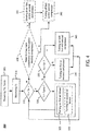
- FIGS. 3-5 there depict a first method (300) for controlling climate systems in accordance with some embodiments of the present disclosure.
- the first method (300) are described in the context of a climate system that includes a first compressor and a second compressor in parallel, i.e., the refrigerant inlets of the first and second compressors are fluidly connected to each other and refrigerant outlets of the first and second compressors are fluidly connected to each other.
- the climate system further includes a condenser disposed downstream of the first and second compressors and fluidly connected to the first and second compressors, and a first air blower positioned proximate the condenser and configured to blow air over the condenser.
- the climate system is installed in a vehicle for cooling a compartment of the vehicle.
- the first method (300) is governed by instructions that are stored in and executed by a controller such as the controller (124) illustrated in FIGS. 1 and 2 . In some embodiments, the first method (300) is governed by instructions that are stored in and executed by an electronic device other than the controller (124) illustrated in FIGS. 1 and 2 .
- the first method (300) includes: receiving a desired temperature for the compartment and an atmosphere temperature outside of the vehicle (step 305); monitoring an interior temperature in the compartment of the vehicle (step 310); determining whether the interior temperature is higher than the desired temperature (step 315); determining whether the interior temperature is higher than the atmosphere temperature (step 320); turning on the first air blower to vent interior air in the compartment, if the interior temperature exceeds both the desired temperature and the atmosphere temperature (step 325); determining whether the thermal load of the compartment exceeds a first thermal threshold, if the interior temperature is higher than the desired temperature but lower than or equal to the atmosphere temperature (step 335); turning on the first compressor or the second compressor if the thermal load of the compartment is less than or equal to a first thermal threshold (step 340); and turning on both the first compressor and the second compressor if the thermal load of the compartment exceeds the first thermal threshold (step 345).
- the climate system includes a second air blower, or the climate system is coupled to an existing air conditioning system and an air blower of the existing air conditioning system serves as a second air blower to the climate system.
- the first method (300) includes an additional or optional step (step 330) that turns on the second air blower to suck in ambient or fresh air into the compartment of the vehicle, if the interior temperature exceeds both the desired temperature and the atmosphere temperature.
- the first and second air blowers may be operated simultaneously, alternately, or independently.
- the first method (300) automatically turns off the first compressor and/or the second compressor when the interior temperature is lowered to the desired temperature or when cooling is no longer desired (step 360).
- the first method (300) before turning off the first compressor and/or second compressor, operates the first compressor at a first low speed range for a first low-speed time period before turning off the first compressor to allow compressor oil drawn back to the first oil sump and/or operates the second compressor at a second low speed range for a second low-speed time period before turning off the second compressor to allow the compressor oil drawn back to the second oil sump (step 355).
- operating the first compressor at the first low speed range for the first low-speed time period is performed every time when the first compressor is to be turned off or every other time when the first compressor is to be turned off.
- operating the second compressor at the second low speed range for the second low-speed time period is performed every time when the second compressor is to be turned off or every other time when the second compressor is to be turned off.
- the first method (300) further includes an additional or optional step 405, to determine whether it is needed to draw back compressor oil to one or more compressors. If it is determined that drawing back compressor oil is needed for a compressor, the first method (300) proceeds to step 355 to slow down that compressor (e.g., operating that compressor at a low speed range for a period of time) before turning it off at step 360. Otherwise, the first method (300) proceeds to step 360 to turn off that compressor. In some embodiments, the determination is based on how long the compressor has been running at a high speed range.
- operating the first compressor at the first low speed range for the first low-speed time period is performed after the first compressor is operated at a first high speed range for a first high-speed time period.
- Operating the second compressor at the second low speed range for the second low-speed time period is performed after the second compressor is operated at a second high speed range for a second high-speed time period.
- the second air blower is selectively in fluidic communication with the ambient, a fresh air system of the vehicle or the compartment of the vehicle through a duct such as a pipe, a conduit, a channel, a tube or the like.
- a door is implemented to control the air flow.
- the first method (300) includes an additional or optional step 505, which opens or closes the door before turning on the second air blower to allow the second air blower to blow the ambient or fresh air into the compartment of the vehicle.
- the second method (600) depicts a second method (600) for controlling climate systems in accordance with some embodiments of the present disclosure.
- the second method (600) are described in the context of a climate system that includes a first compressor and a second compressor in parallel, i.e., the refrigerant inlets of the first and second compressors are fluidly connected to each other and refrigerant outlets of the first and second compressors are fluidly connected to each other.
- the climate system further includes a condenser disposed downstream of the first and second compressors and fluidly connected to the first and second compressors.
- the climate system is installed in a vehicle for cooling a compartment of the vehicle.
- the second method (600) is governed by instructions that are stored in and executed by a controller such as the controller (124) illustrated in FIGS. 1 and 2 . In some embodiments, the second method (600) is governed by instructions that are stored in and executed by an electronic device other than the controller (124) illustrated in FIGS. 1 and 2 .
- the second method (600) includes: receiving a desired temperature for the compartment and an atmosphere temperature outside of the vehicle (step 305); determining whether a thermal load of the compartment exceeds a first thermal threshold (step 335); turning on the first compressor or the second compressor if the thermal load of the compartment is less than or equal to a first thermal threshold (step 340); turning on both the first compressor and the second compressor if the thermal load of the compartment exceeds the first thermal threshold (step 345); and performing one or more of the following: operating the first compressor at a first low speed range for a first low-speed time period before turning off the first compressor to allow compressor oil drawn back to the first oil sump; and operating the second compressor at a second low speed range for a second low-speed time period before turning off the second compressor to allow the compressor oil drawn back to the second oil sump (step 355).
- the second method (600) prior to operating the first and/or second compressor at a low speed range (step 355), the second method (600) further include one or more of the following additional or optional steps: determining whether it is needed to draw back compressor oil to the first compressor based on whether the first compressor has been running at a first high speed range and for how long; and determining whether it is needed to draw back the compressor oil to the second compressor based on whether the second compressor has been running at a second high speed range and for how long (step 405).
- the second method (600) further includes one or more of the following: operating the first compressor at a first low speed range for a first low-speed time period to draw back compressor oil to the first compressor if the first compressor has been operated at the first high speed range for a first high-speed time period; and operating the second compressor at a second low speed range for a second low-speed time period to draw back compressor to the second compressor if it is determined that the second compressor has been operated at the second high speed range for a second high-speed time period.
- a first compressor could be termed a second compressor, and, similarly, a second compressor could be termed a first compressor, without changing the meaning of the description, so long as all occurrences of the "first compressor” are renamed consistently and all occurrences of the "second compressor” are renamed consistently.
Landscapes
- Engineering & Computer Science (AREA)
- Physics & Mathematics (AREA)
- Thermal Sciences (AREA)
- Mechanical Engineering (AREA)
- General Engineering & Computer Science (AREA)
- Air-Conditioning For Vehicles (AREA)
- Air Conditioning Control Device (AREA)
- Control Of Positive-Displacement Pumps (AREA)
Priority Applications (1)
| Application Number | Priority Date | Filing Date | Title |
|---|---|---|---|
| EP23176784.9A EP4242025A3 (de) | 2016-08-22 | 2016-12-15 | Klimasystem mit parallelen kompressoren |
Applications Claiming Priority (2)
| Application Number | Priority Date | Filing Date | Title |
|---|---|---|---|
| US201662378135P | 2016-08-22 | 2016-08-22 | |
| US15/280,876 US10081226B2 (en) | 2016-08-22 | 2016-09-29 | Parallel compressors climate system |
Related Child Applications (1)
| Application Number | Title | Priority Date | Filing Date |
|---|---|---|---|
| EP23176784.9A Division EP4242025A3 (de) | 2016-08-22 | 2016-12-15 | Klimasystem mit parallelen kompressoren |
Publications (3)
| Publication Number | Publication Date |
|---|---|
| EP3287718A1 true EP3287718A1 (de) | 2018-02-28 |
| EP3287718C0 EP3287718C0 (de) | 2023-06-07 |
| EP3287718B1 EP3287718B1 (de) | 2023-06-07 |
Family
ID=57570182
Family Applications (2)
| Application Number | Title | Priority Date | Filing Date |
|---|---|---|---|
| EP16204256.8A Active EP3287718B1 (de) | 2016-08-22 | 2016-12-15 | Klimasystem mit parallelen kompressoren |
| EP23176784.9A Pending EP4242025A3 (de) | 2016-08-22 | 2016-12-15 | Klimasystem mit parallelen kompressoren |
Family Applications After (1)
| Application Number | Title | Priority Date | Filing Date |
|---|---|---|---|
| EP23176784.9A Pending EP4242025A3 (de) | 2016-08-22 | 2016-12-15 | Klimasystem mit parallelen kompressoren |
Country Status (3)
| Country | Link |
|---|---|
| US (3) | US10081226B2 (de) |
| EP (2) | EP3287718B1 (de) |
| CN (1) | CN107757304A (de) |
Cited By (4)
| Publication number | Priority date | Publication date | Assignee | Title |
|---|---|---|---|---|
| WO2020092744A2 (en) | 2018-10-31 | 2020-05-07 | Emerson Climate Technologies, Inc. | Oil control for climate-control system |
| US12230828B2 (en) | 2021-06-04 | 2025-02-18 | Ethium, Llc | Lithium-ion battery charging system for fork lifts |
| US12266953B1 (en) | 2020-08-17 | 2025-04-01 | Econtrols, Llc | Dual chemistry rechargeable battery system for use in electric APU-equipped commercial trucks |
| US12451527B2 (en) | 2017-07-13 | 2025-10-21 | Ethium, Llc | Modular lithium-ion battery system for fork lifts |
Families Citing this family (13)
| Publication number | Priority date | Publication date | Assignee | Title |
|---|---|---|---|---|
| US10414241B2 (en) | 2016-06-30 | 2019-09-17 | Emerson Climate Technologies, Inc. | Systems and methods for capacity modulation through eutectic plates |
| US10569620B2 (en) | 2016-06-30 | 2020-02-25 | Emerson Climate Technologies, Inc. | Startup control systems and methods to reduce flooded startup conditions |
| US20180361830A1 (en) * | 2017-06-19 | 2018-12-20 | Ford Global Technologies, Llc | Dual electric drive a/c compressor system and method |
| GB201719399D0 (en) * | 2017-11-22 | 2018-01-03 | Bennamann Services Ltd | Liquid methane storage and fuel delivery system |
| US11421681B2 (en) * | 2018-04-19 | 2022-08-23 | Emerson Climate Technologies, Inc. | Multiple-compressor system with suction valve and method of controlling suction valve |
| CN109774411B (zh) * | 2018-12-29 | 2021-01-29 | 吴志新 | 一种基于高压氢气泄压的电动汽车空调制冷系统及方法 |
| US11993155B2 (en) | 2019-05-29 | 2024-05-28 | Illinois Tool Works Inc. | Auxiliary power unit air conditioning for truck cab cooling |
| US11892211B2 (en) | 2021-05-23 | 2024-02-06 | Copeland Lp | Compressor flow restrictor |
| DE102021207027A1 (de) | 2021-07-05 | 2023-01-05 | Mitsubishi Heavy Industries, Ltd. | Kältemaschine für den Transport |
| CN114312206B (zh) * | 2021-07-21 | 2023-11-17 | 华为数字能源技术有限公司 | 电动车辆的热管理系统以及电动车辆 |
| CN114393976B (zh) * | 2022-02-24 | 2023-08-15 | 湖南行必达网联科技有限公司 | 一种卧铺区域智能空调装置、控制方法及汽车 |
| CN115230430B (zh) * | 2022-07-25 | 2025-11-28 | 安徽江淮汽车集团股份有限公司 | 用于车载空调的双压缩机控制系统 |
| US12422173B2 (en) | 2022-08-19 | 2025-09-23 | Copeland Lp | Multiple-compressor system with oil balance control |
Citations (8)
| Publication number | Priority date | Publication date | Assignee | Title |
|---|---|---|---|---|
| EP1703231A1 (de) * | 2005-02-25 | 2006-09-20 | Lg Electronics Inc. | Ölstandausgleichsanlage für mehrere Verdichter und zugehöriges Regelverfahren |
| US20080209924A1 (en) * | 2007-03-02 | 2008-09-04 | Lg Electronics Inc. | Air conditioner and control method thereof |
| DE102007028851A1 (de) * | 2007-06-22 | 2008-12-24 | Konvekta Ag | Klimaanlage |
| KR20090068136A (ko) * | 2007-12-22 | 2009-06-25 | 삼성전자주식회사 | 공기조화장치 |
| EP2196748A2 (de) * | 2008-12-11 | 2010-06-16 | Fujitsu General Limited | Kühlvorrichtung und Steuerverfahren dafür |
| EP2320160A1 (de) * | 2008-08-22 | 2011-05-11 | Panasonic Corporation | Gefrierzyklusvorrichtung |
| WO2012158326A1 (en) * | 2011-05-16 | 2012-11-22 | Carrier Corporation | Multi-compressor refrigeration system |
| WO2015076872A1 (en) * | 2013-11-25 | 2015-05-28 | Thermo King Corporation | Fresh air control for a transport refrigeration unit |
Family Cites Families (307)
| Publication number | Priority date | Publication date | Assignee | Title |
|---|---|---|---|---|
| US2722050A (en) | 1949-03-03 | 1955-11-01 | Gibson Refrigerator Co | Method of making a fluid chamber |
| US2789234A (en) | 1956-01-16 | 1957-04-16 | Eastern Malleable Iron Company | Auxiliary power unit for vehicles |
| US3225819A (en) | 1962-08-31 | 1965-12-28 | Daniel Moretti | Apparatus and method for air to air heat exchange |
| US3176502A (en) | 1963-07-26 | 1965-04-06 | Pratt & Whitney Inc | Pneumatic gage |
| US3360958A (en) * | 1966-01-21 | 1968-01-02 | Trane Co | Multiple compressor lubrication apparatus |
| US3627030A (en) | 1970-01-02 | 1971-12-14 | Trane Co | Heating cooling dehumidifying airconditioning system control |
| US3590910A (en) | 1970-01-02 | 1971-07-06 | Trane Co | Heating-cooling air-conditioning system control |
| US3880224A (en) | 1971-02-23 | 1975-04-29 | Gas Dev Corp | 3-Stream S-wheel and cooling mode operation |
| JPS5032121B2 (de) | 1971-10-09 | 1975-10-17 | ||
| US3948060A (en) | 1972-05-24 | 1976-04-06 | Andre Jean Gaspard | Air conditioning system particularly for producing refrigerated air |
| US3807087A (en) | 1972-10-10 | 1974-04-30 | Mattel Inc | Automatic battery cut-off system for electric motor-driven toy vehicles using rechargeable batteries |
| US3844130A (en) | 1973-07-09 | 1974-10-29 | M Wahnish | Automobile air conditioning system employing auxiliary prime motor |
| GB1464453A (en) | 1973-09-21 | 1977-02-16 | Daikin Ind Ltd | Refrigerating apparatus |
| US3885398A (en) | 1973-12-10 | 1975-05-27 | Claude W Dawkins | Air conditioning system for a motor home vehicle or the like |
| US5227704A (en) | 1974-06-24 | 1993-07-13 | General Electric Company | Motor controls, refrigeration systems and methods of motor operation and control |
| US4015182A (en) | 1974-06-24 | 1977-03-29 | General Electric Company | Refrigeration system and control therefor |
| US4459519A (en) | 1974-06-24 | 1984-07-10 | General Electric Company | Electronically commutated motor systems and control therefor |
| US3995443A (en) | 1975-01-02 | 1976-12-07 | Iversen Rudolf O | Air conditioning system |
| US4034801A (en) | 1975-04-14 | 1977-07-12 | Robert J. Sigel, Inc. | Optimum environmental control system for a building |
| US4071080A (en) | 1976-01-14 | 1978-01-31 | Bridgers Frank H | Air conditioning system |
| US4280330A (en) | 1977-09-19 | 1981-07-28 | Verdell Harris | Vehicle heating and cooling system |
| US4271677A (en) | 1978-03-27 | 1981-06-09 | Forrest Harr | Self-contained roof-mounted vehicle air-conditioning system |
| US4217764A (en) | 1978-07-05 | 1980-08-19 | Sheller-Globe Corporation | Roof mounted motor vehicle air conditioner |
| US4577679A (en) | 1978-10-25 | 1986-03-25 | Hibshman Henry J | Storage systems for heat or cold including aquifers |
| SE440275B (sv) | 1979-03-21 | 1985-07-22 | Svante Thunberg | Vermevexlare till anleggningar for ventilering av lokaler |
| US4266405A (en) | 1979-06-06 | 1981-05-12 | Allen Trask | Heat pump refrigerant circuit |
| US4324286A (en) | 1980-03-24 | 1982-04-13 | The Trane Company | Control for vehicle temperature conditioning system |
| JPS6033099Y2 (ja) | 1980-04-22 | 1985-10-02 | 本田技研工業株式会社 | シ−トの取付装置 |
| US4412425A (en) | 1980-12-09 | 1983-11-01 | Nippon Soken, Inc. | Air conditioning and ventilation system |
| US4383802A (en) * | 1981-07-06 | 1983-05-17 | Dunham-Bush, Inc. | Oil equalization system for parallel connected compressors |
| US4448157A (en) | 1982-03-08 | 1984-05-15 | Eckstein Robert J | Auxiliary power unit for vehicles |
| US4617472A (en) | 1983-07-19 | 1986-10-14 | Nuvatec, Inc. | Recreational vehicle power control system |
| JPH0758069B2 (ja) | 1983-09-09 | 1995-06-21 | 株式会社日立製作所 | 圧縮機のモータ制御装置 |
| SE438061B (sv) | 1984-02-01 | 1985-03-25 | Thermo Produkter B S Ab | Kylanleggning |
| US4641502A (en) | 1985-01-09 | 1987-02-10 | The Duo-Therm Corporation | Roof mount air conditioner |
| JPS61210238A (ja) | 1985-03-15 | 1986-09-18 | Nissan Motor Co Ltd | アイドリング回転数制御装置 |
| US4667480A (en) | 1986-09-22 | 1987-05-26 | General Electric Company | Method and apparatus for controlling an electrically driven automotive air conditioner |
| US4945977A (en) | 1987-01-05 | 1990-08-07 | Agaro Raymond D | Combination vehicle heating and cooling system |
| US4893479A (en) | 1987-03-20 | 1990-01-16 | Ranco Electronics Division | Compressor drive system |
| KR960007043B1 (ko) | 1987-04-30 | 1996-05-27 | 가부시기가이샤 히다찌 세이사꾸쇼 | 철도차량용 공기조화장치 |
| JPH01195190A (ja) | 1987-08-06 | 1989-08-07 | Morris Ostrowiecki | 収納式フェンダー |
| US4748825A (en) | 1987-10-29 | 1988-06-07 | Thermo King Corporation | Bus air conditioning unit |
| US4825663A (en) | 1987-11-16 | 1989-05-02 | Paccar Inc. | Auxiliary air conditioning system for trucks and other heavy duty vehicles |
| US4982576A (en) | 1987-12-10 | 1991-01-08 | Murray Corporation | Air conditioner charging station with same refrigerant return and method |
| US4841733A (en) | 1988-01-07 | 1989-06-27 | Dussault David R | Dri-Pc humidity and temperature controller |
| US4952283A (en) | 1988-02-05 | 1990-08-28 | Besik Ferdinand K | Apparatus for ventilation, recovery of heat, dehumidification and cooling of air |
| US4856078A (en) | 1988-03-23 | 1989-08-08 | Zenith Electronics Corporation | DC fan speed control |
| FI79810C (fi) | 1988-03-30 | 1990-03-12 | Kalervo Virtanen | Uppvaermnings- och luftkonditioneringssystem i en buss. |
| JPH02128915A (ja) | 1988-11-09 | 1990-05-17 | Nippon Denso Co Ltd | 車両用冷房冷凍装置 |
| US5067652A (en) | 1989-03-02 | 1991-11-26 | Enander Harold R | Supplemental vehicle heating method and apparatus with long heating cycle |
| US5025634A (en) | 1989-04-25 | 1991-06-25 | Dressler William E | Heating and cooling apparatus |
| US4947657A (en) | 1989-06-05 | 1990-08-14 | Kalmbach John F | Auxiliary air conditioning apparatus and method for air conditioned vehicles |
| US5125236A (en) | 1989-09-15 | 1992-06-30 | Onan Corporation | Combined generator set and air conditioning compressor drive system |
| US5095308A (en) | 1990-01-09 | 1992-03-10 | Southern Marine Research, Inc. | Transceiver with battery saver and method of using same |
| US5230719A (en) | 1990-05-15 | 1993-07-27 | Erling Berner | Dehumidification apparatus |
| US5046327A (en) | 1990-07-17 | 1991-09-10 | Walker Steve A | Air conditioner conversion kits for vans and recreational vehicles |
| US5396779A (en) | 1990-09-14 | 1995-03-14 | Nartron Corporation | Environmental control system |
| US5316074A (en) | 1990-10-12 | 1994-05-31 | Nippondenso Co., Ltd. | Automotive hair conditioner |
| US5205781A (en) | 1991-01-18 | 1993-04-27 | Naldec Corporation | Preliminary ventilation device for vehicles |
| JP2747379B2 (ja) | 1991-05-31 | 1998-05-06 | 昭和アルミニウム株式会社 | 熱交換器 |
| US5307645A (en) | 1991-07-02 | 1994-05-03 | Pannell Bobby L | Air conditioning system for a recreational vehicle |
| JP3104308B2 (ja) | 1991-07-30 | 2000-10-30 | 松下電器産業株式会社 | 電気自動車用空調装置 |
| JP3119281B2 (ja) | 1991-10-14 | 2000-12-18 | 株式会社デンソー | 車両用空調装置 |
| US5170639A (en) | 1991-12-10 | 1992-12-15 | Chander Datta | Cascade refrigeration system |
| JP3085335B2 (ja) | 1991-12-27 | 2000-09-04 | 株式会社デンソー | 空気調和装置 |
| US5333678A (en) | 1992-03-06 | 1994-08-02 | Onan Corporation | Auxiliary power unit |
| FR2689215B1 (fr) | 1992-03-30 | 1994-07-01 | Sari | Installation de traitement d'air. |
| FR2690387B1 (fr) | 1992-04-28 | 1995-06-23 | Valeo Thermique Habitacle | Procede et dispositif pour abaisser la temperature de l'air dans l'habitacle d'un vehicule hors circulation. |
| US5271245A (en) * | 1992-08-20 | 1993-12-21 | Ac&R Components, Inc. | Two-stage helical oil separator |
| JP3084949B2 (ja) | 1992-08-31 | 2000-09-04 | 松下電器産業株式会社 | 自動車用電動コンプレッサーの制御駆動装置 |
| US5275012A (en) | 1993-01-07 | 1994-01-04 | Ford Motor Company | Climate control system for electric vehicle |
| US5327997A (en) * | 1993-01-22 | 1994-07-12 | Temprite, Inc. | Lubrication management system |
| US5324229A (en) | 1993-01-26 | 1994-06-28 | American Standard Inc. | Two section economizer damper assembly providing improved air mixing |
| US5426953A (en) | 1993-02-05 | 1995-06-27 | Meckler; Milton | Co-sorption air dehumidifying and pollutant removal system |
| US5586613A (en) | 1993-04-22 | 1996-12-24 | The Texas A&M University System | Electrically peaking hybrid system and method |
| US5775415A (en) | 1993-07-07 | 1998-07-07 | Nippondenso Co., Ltd. | Air conditioning system |
| JP3312161B2 (ja) | 1993-12-24 | 2002-08-05 | 株式会社豊田中央研究所 | 水素燃料自動車 |
| US5465589A (en) | 1993-09-07 | 1995-11-14 | Navistar International Transportation Corp. | Idle automated A/C system |
| JP3380316B2 (ja) | 1993-12-28 | 2003-02-24 | 本田技研工業株式会社 | 車両用エアコンディショニング機器制御装置 |
| WO1995023919A1 (en) | 1994-03-01 | 1995-09-08 | Auxiliary Power Dynamics, Llc | Small compact auxiliary power system for heavy duty diesel engine installations |
| US5524442A (en) | 1994-06-27 | 1996-06-11 | Praxair Technology, Inc. | Cooling system employing a primary, high pressure closed refrigeration loop and a secondary refrigeration loop |
| US6059016A (en) | 1994-08-11 | 2000-05-09 | Store Heat And Produce Energy, Inc. | Thermal energy storage and delivery system |
| DE4433836C1 (de) | 1994-09-22 | 1995-11-09 | Daimler Benz Ag | Vorrichtung zur Beheizung eines Innenraumes eines Elektrofahrzeuges |
| CA2134168C (en) | 1994-10-24 | 2002-06-11 | Frederic Lagace | Ventilation system |
| DE4440044C2 (de) | 1994-11-09 | 2001-12-20 | Carrier Suetrak Gmbh | Klimagerät |
| FR2727902A1 (fr) | 1994-12-09 | 1996-06-14 | Valeo Thermique Habitacle | Dispositif pour la climatisation d'un vehicule en circulation et en stationnement |
| US6112535A (en) | 1995-04-25 | 2000-09-05 | General Electric Company | Compressor including a motor and motor control in the compressor housing and method of manufacture |
| US5761918A (en) * | 1995-05-01 | 1998-06-09 | Index Sensors And Controls, Inc. | Integrated controller for commercial vehicle air conditioning system |
| US6038879A (en) | 1995-08-08 | 2000-03-21 | Yvon Turcotte | Combined air exchange and air conditioning unit |
| JPH0976740A (ja) | 1995-09-08 | 1997-03-25 | Aqueous Res:Kk | ハイブリッド車両 |
| US5657638A (en) | 1995-10-02 | 1997-08-19 | General Electric Company | Two speed control circuit for a refrigerator fan |
| US5901572A (en) | 1995-12-07 | 1999-05-11 | Rocky Research | Auxiliary heating and air conditioning system for a motor vehicle |
| JPH09163791A (ja) | 1995-12-07 | 1997-06-20 | Sanden Corp | 電動式圧縮機の駆動方法及び駆動装置 |
| FR2742702B1 (fr) | 1995-12-22 | 1998-02-13 | Valeo Climatisation | Installation de climatisation, notamment d'un vehicule automobile |
| JP3707119B2 (ja) | 1995-12-25 | 2005-10-19 | 株式会社デンソー | 車両用空調装置 |
| US6209333B1 (en) | 1996-01-22 | 2001-04-03 | Rene F. Bascobert | Mobile air conditioning system and control mechanism |
| JPH09318177A (ja) | 1996-05-27 | 1997-12-12 | Matsushita Refrig Co Ltd | 多室冷暖房装置 |
| JPH1053019A (ja) | 1996-06-03 | 1998-02-24 | Denso Corp | 車両用空調装置 |
| US5901780A (en) | 1996-06-24 | 1999-05-11 | Rocky Research | Auxiliary active heating and air conditioning system for motor vehicle applications |
| DE19628585C2 (de) | 1996-07-16 | 2001-12-20 | Danfoss As | Verfahren zum Kommutieren eines bürstenlosen Motors und Speiseschaltung für einen bürstenlosen Motor |
| US5682757A (en) | 1996-08-01 | 1997-11-04 | Smart Power Systems, Inc. | Condensate liquid management system for air conditioner |
| DK174114B1 (da) | 1996-10-09 | 2002-06-24 | Danfoss Compressors Gmbh | Fremgangsmåde til hastighedsregulering af en kompressor samt styring, der gør brug af fremgangsmåden |
| US5982643A (en) | 1996-10-10 | 1999-11-09 | Progressive Dynamics, Inc. | Power converter with selectively variable output and controller and display system therefor |
| US5819549A (en) | 1996-10-16 | 1998-10-13 | Minnesota Mining And Manufacturing Company | Secondary loop refrigeration system |
| EP0838640A3 (de) * | 1996-10-28 | 1998-06-17 | Matsushita Refrigeration Company | Ölstandausgleichsanlage für mehrere Verdichter |
| JP3326355B2 (ja) | 1997-04-02 | 2002-09-24 | 三洋電機株式会社 | 空気調和装置の冷媒分流装置 |
| JP3305974B2 (ja) | 1997-03-05 | 2002-07-24 | トヨタ自動車株式会社 | ハイブリッド車用空調制御装置 |
| US5899081A (en) | 1997-03-31 | 1999-05-04 | White Consolidated Industries, Inc. | Heating and cooling unit using power inverter with battery |
| US5898995A (en) | 1997-09-24 | 1999-05-04 | General Motors Corporation | Method of manufacture of a primary heat exchanger jacketed by a secondary heat exchanger |
| US6073456A (en) | 1997-10-09 | 2000-06-13 | Denso Corporation | Air-conditioning device for hybrid vehicle |
| DE19745028A1 (de) | 1997-10-11 | 1999-04-15 | Behr Gmbh & Co | Verfahren und Vorrichtung zur verdampfervereisungsgeschützten Klimaanlagensteuerung |
| TW345346U (en) | 1997-12-09 | 1998-11-11 | Sunonwealth Electr Mach Ind Co | Improved structure for radiator fan motor |
| US6072261A (en) | 1998-02-12 | 2000-06-06 | Delta Electronics, Inc. | Motor construction |
| US6029465A (en) | 1998-02-14 | 2000-02-29 | Bascobert; Rene F | Control system for mobile air conditioning apparatus |
| US6111731A (en) | 1998-02-26 | 2000-08-29 | Technical Products Group, Inc. | Motor controller for preventing excessive battery discharging |
| US5921092A (en) | 1998-03-16 | 1999-07-13 | Hussmann Corporation | Fluid defrost system and method for secondary refrigeration systems |
| JPH11301255A (ja) | 1998-04-22 | 1999-11-02 | Toyota Autom Loom Works Ltd | 車両用空調装置 |
| EP0958952A1 (de) | 1998-05-20 | 1999-11-24 | Carrier Corporation | LKW-Kühlaggregat mit einem horizontalen Rotationskolbenverdichter |
| AU4197999A (en) | 1998-05-22 | 1999-12-13 | Bergstrom, Inc. | Auxiliary heating and air conditioning system for a motor vehicle |
| US6457324B2 (en) | 1998-05-22 | 2002-10-01 | Bergstrom, Inc. | Modular low-pressure delivery vehicle air conditioning system having an in-cab cool box |
| US6038877A (en) | 1998-05-22 | 2000-03-21 | Bergstrom, Inc. | Modular low pressure delivery vehicle air conditioning system |
| AT406363B (de) | 1998-06-10 | 2000-04-25 | Integral Verkehrstechnik Ag | Fahrzeug, insbesondere schienenfahrzeug |
| US20020014329A1 (en) | 1998-06-29 | 2002-02-07 | Peter Carr | Integrated heating and cooling system for a vehicle |
| JP2000110734A (ja) | 1998-08-07 | 2000-04-18 | Toyota Autom Loom Works Ltd | ハイブリッドコンプレッサ及びその制御方法 |
| JP2000108651A (ja) | 1998-10-06 | 2000-04-18 | Denso Corp | 車両用空調装置 |
| DE19903769C2 (de) | 1999-01-30 | 2002-09-12 | Webasto Vehicle Sys Int Gmbh | Verfahren zum Stand-Klimatisieren eines Kraftfahrzeugs |
| JP4092805B2 (ja) | 1999-03-19 | 2008-05-28 | 株式会社デンソー | 車両用空調装置 |
| CZ20004385A3 (cs) | 1999-03-25 | 2001-08-15 | General Electric Company | Elektrický motor se způsobem montáže pomocí zaklapávacích spojení |
| US6185959B1 (en) | 1999-04-09 | 2001-02-13 | Eaton Corporation | Refrigerant system components with cartridge type thermal expansion valve and method of making same |
| JP4218123B2 (ja) | 1999-04-15 | 2009-02-04 | 株式会社デンソー | 空調装置 |
| US6205795B1 (en) | 1999-05-21 | 2001-03-27 | Thomas J. Backman | Series secondary cooling system |
| US6467279B1 (en) | 1999-05-21 | 2002-10-22 | Thomas J. Backman | Liquid secondary cooling system |
| US6253563B1 (en) | 1999-06-03 | 2001-07-03 | The United States Of America As Represented By The Administrator Of The National Aeronautics And Space Administration | Solar-powered refrigeration system |
| JP4067701B2 (ja) | 1999-06-10 | 2008-03-26 | カルソニックカンセイ株式会社 | 車両用空調装置 |
| US6125642A (en) * | 1999-07-13 | 2000-10-03 | Sporlan Valve Company | Oil level control system |
| US6282919B1 (en) | 1999-07-20 | 2001-09-04 | Rocky Research | Auxiliary active motor vehicle heating and air conditioning system |
| DE19942029B4 (de) | 1999-09-03 | 2005-12-01 | Temic Automotive Electric Motors Gmbh | Permanentmagnetrotor für einen bürstenlosen Elektromotor |
| DE19954308C2 (de) | 1999-11-11 | 2003-11-13 | Daimler Chrysler Ag | Klimaanlage für Fahrgastzellen von Fahrzeugen |
| US6193475B1 (en) | 1999-11-23 | 2001-02-27 | Thomas Industries Inc. | Compressor assembly |
| US6205802B1 (en) | 2000-01-05 | 2001-03-27 | Carrier Corporation | Travel coach air conditioning system |
| US6213867B1 (en) | 2000-01-12 | 2001-04-10 | Air Handling Engineering Ltd. | Venturi type air distribution system |
| JP3480410B2 (ja) | 2000-01-28 | 2003-12-22 | 株式会社デンソー | 車両用空調装置 |
| US6575228B1 (en) | 2000-03-06 | 2003-06-10 | Mississippi State Research And Technology Corporation | Ventilating dehumidifying system |
| FR2806226B1 (fr) | 2000-03-07 | 2002-05-31 | Valeo Climatisation | Dispositif de commande d'un compresseur electrique pour circuit de climatisation |
| JP2001289534A (ja) | 2000-04-07 | 2001-10-19 | Toyota Autom Loom Works Ltd | 空調用ユニット |
| DE10019580B4 (de) | 2000-04-20 | 2010-06-10 | Behr Gmbh & Co. Kg | Einrichtung zum Kühlen eines Innenraumes eines Kraftfahrzeugs |
| US6405793B1 (en) | 2000-05-03 | 2002-06-18 | Delphi Technologies, Inc. | Secondary loop system for passenger compartment heating and cooling |
| JP4426737B2 (ja) | 2000-06-28 | 2010-03-03 | 東芝キヤリア株式会社 | 車両用冷凍装置 |
| AU2001283140B2 (en) | 2000-08-18 | 2005-07-28 | Nnt, Inc. | System, method and computer program product for remote vehicle diagnostics, monitoring, configuring and reprogramming |
| US6453678B1 (en) | 2000-09-05 | 2002-09-24 | Kabin Komfort Inc | Direct current mini air conditioning system |
| JP2002079828A (ja) | 2000-09-07 | 2002-03-19 | Suzuki Motor Corp | 電気自動車用空調装置 |
| US6318103B1 (en) | 2000-09-22 | 2001-11-20 | Delphi Technologies, Inc. | Evaporator mounted blower speed control |
| JP4438206B2 (ja) | 2000-09-28 | 2010-03-24 | 株式会社デンソー | 駆動装置および車両用空調装置 |
| FR2814986B1 (fr) | 2000-10-11 | 2003-02-07 | Valeo Climatisation | Installation de climatisation de vehicule a deux zones de mixage |
| US6745585B2 (en) | 2000-12-26 | 2004-06-08 | Visteon Global Technologies, Inc. | Electric air conditioner sustain system |
| JP3736437B2 (ja) | 2000-12-28 | 2006-01-18 | 株式会社デンソー | ハイブリッド車用空調装置 |
| JP2003056461A (ja) | 2001-02-15 | 2003-02-26 | Denso Corp | 圧縮機の複合駆動システム |
| JP2002243246A (ja) | 2001-02-15 | 2002-08-28 | Sanden Corp | 空調装置 |
| JP2002240547A (ja) | 2001-02-16 | 2002-08-28 | Toyota Industries Corp | 車両用空調装置及びその運転方法 |
| JP3967116B2 (ja) | 2001-04-24 | 2007-08-29 | 株式会社日本自動車部品総合研究所 | 圧縮機の複合駆動装置 |
| US6637230B2 (en) | 2001-04-27 | 2003-10-28 | Denso Corporation | Automotive air-conditioner having sub-compressor driven by electric motor |
| US6981544B2 (en) | 2001-04-27 | 2006-01-03 | Denso Corporation | Air-conditioning apparatus including motor-driven compressor for idle stopping vehicles |
| JP2003074476A (ja) | 2001-08-31 | 2003-03-12 | Nippon Soken Inc | 圧縮機制御装置 |
| EP1300562A1 (de) | 2001-10-04 | 2003-04-09 | Visteon Global Technologies, Inc. | Steuerung für eine aufgeladene Brennkraftmaschine mit elektronisch geregeltem Ansaugluftverdichter |
| JP2003130391A (ja) | 2001-10-18 | 2003-05-08 | Sanyo Electric Co Ltd | 空気調和機 |
| US6543245B1 (en) | 2001-11-08 | 2003-04-08 | Thermo King Corporation | Multi-temperature cold plate refrigeration system |
| US6965818B2 (en) | 2001-11-28 | 2005-11-15 | Onan Corporation | Mobile energy management system |
| JP2003214729A (ja) | 2002-01-28 | 2003-07-30 | Toshiba Kyaria Kk | 空気調和機 |
| US6725134B2 (en) | 2002-03-28 | 2004-04-20 | General Electric Company | Control strategy for diesel engine auxiliary loads to reduce emissions during engine power level changes |
| US6571566B1 (en) | 2002-04-02 | 2003-06-03 | Lennox Manufacturing Inc. | Method of determining refrigerant charge level in a space temperature conditioning system |
| US6889762B2 (en) | 2002-04-29 | 2005-05-10 | Bergstrom, Inc. | Vehicle air conditioning and heating system providing engine on and engine off operation |
| US9694651B2 (en) | 2002-04-29 | 2017-07-04 | Bergstrom, Inc. | Vehicle air conditioning and heating system providing engine on and off operation |
| JP3917002B2 (ja) | 2002-05-15 | 2007-05-23 | サンデン株式会社 | 車両用空調装置 |
| US6865901B2 (en) * | 2002-05-29 | 2005-03-15 | Webasto Thermosysteme International Gmbh | System with an internal combustion engine, a fuel cell and a climate control unit for heating and/or cooling the interior of a motor vehicle and process for the operation thereof |
| KR100440157B1 (ko) | 2002-06-25 | 2004-07-12 | 현대자동차주식회사 | 모터 직결형 차량의 하이브리드 에어컨 시스템 제어장치및 방법 |
| CN100358225C (zh) | 2002-06-26 | 2007-12-26 | 阿莫泰克有限公司 | 径向铁芯型双转子无刷直流电动机及其制造方法 |
| JP4060142B2 (ja) | 2002-07-30 | 2008-03-12 | 本田技研工業株式会社 | 車両用空調装置 |
| EP1400764B1 (de) | 2002-09-19 | 2006-05-31 | Franz Adolf Kröter | Warmwasserbereitungsanlage |
| US6932148B1 (en) * | 2002-10-07 | 2005-08-23 | Scs Frigette | Vehicle heating and cooling system |
| JP4070684B2 (ja) | 2002-10-18 | 2008-04-02 | 株式会社デンソー | ハイブリッドコンプレッサ装置 |
| JP2004189175A (ja) | 2002-12-13 | 2004-07-08 | Denso Corp | 車両用空調装置 |
| CN100376416C (zh) | 2003-02-28 | 2008-03-26 | 株式会社电装 | 用于车辆空调装置的压缩机控制系统 |
| US7135799B2 (en) | 2003-03-19 | 2006-11-14 | Pacsci Motion Control, Inc. | Method for winding a stator of multi-phase motors |
| TWI315383B (en) | 2003-03-24 | 2009-10-01 | Sanyo Electric Co | Refrigerant cycle apparatus |
| US6915651B2 (en) | 2003-05-05 | 2005-07-12 | Carrier Corporation | Horizontal rotary compressor in a bus air conditioner |
| JP4350972B2 (ja) | 2003-05-08 | 2009-10-28 | ヤマハモーターエレクトロニクス株式会社 | 回転電機の電機子 |
| JP2005001523A (ja) | 2003-06-12 | 2005-01-06 | Honda Motor Co Ltd | 車両用空調装置 |
| US7096925B2 (en) | 2003-06-19 | 2006-08-29 | General Motors Corporation | Modular electric HVAC systems for vehicles |
| JP2005033941A (ja) | 2003-07-08 | 2005-02-03 | Toshiba Corp | 永久磁石モータの固定子鉄心及び永久磁石モータ |
| US7007493B2 (en) | 2003-07-21 | 2006-03-07 | Delphi Technologies, Inc. | Front-end integral air-conditioning unit |
| JP4590833B2 (ja) | 2003-07-24 | 2010-12-01 | トヨタ自動車株式会社 | 冷却システムを備える移動体 |
| JP2005081960A (ja) | 2003-09-08 | 2005-03-31 | Matsushita Electric Ind Co Ltd | 車両用冷房装置の運転方法 |
| CN1878991A (zh) * | 2003-10-08 | 2006-12-13 | 谷轮公司 | 分布式的冷凝单元 |
| US7246502B2 (en) | 2003-12-12 | 2007-07-24 | Trans/Air Manufacturing Corp | Self-contained flush-mount bulkhead air conditioning unit with novel evaporator/blower assembly housing |
| US7316119B2 (en) | 2004-03-25 | 2008-01-08 | Dometic Environmental Corporation | HVAC system for truck sleepers |
| JP4391874B2 (ja) | 2004-04-19 | 2009-12-24 | 本田技研工業株式会社 | 車両の空調装置 |
| US20050257545A1 (en) | 2004-05-24 | 2005-11-24 | Ziehr Lawrence P | Dual compressor HVAC system |
| US6988371B2 (en) | 2004-05-25 | 2006-01-24 | General Motors Corporation | Automotive HVAC system and method of operating same utilizing evaporator freezing |
| US7350368B2 (en) | 2004-09-01 | 2008-04-01 | Behr Gmbh & Co. Kg | Stationary vehicle air conditioning system |
| US7290400B2 (en) * | 2004-09-01 | 2007-11-06 | Behr Gmbh & Co. Kg | Stationary vehicle air conditioning system and method |
| US7150159B1 (en) | 2004-09-29 | 2006-12-19 | Scs Frigette | Hybrid auxiliary power unit for truck |
| KR20060033358A (ko) | 2004-10-15 | 2006-04-19 | 삼성전자주식회사 | 다실형 공기 조화기의 압축기 제어장치 및 방법 |
| US7614242B1 (en) | 2004-11-23 | 2009-11-10 | Carlos Quesada Saborio | Transport refrigeration system |
| US7681630B2 (en) | 2004-12-07 | 2010-03-23 | Cnh America Llc | HVAC system for a work vehicle |
| KR100620502B1 (ko) | 2005-01-10 | 2006-09-13 | 정인숙 | 열교환기 및 이를 이용한 열교환 환기장치 |
| DE102005004950A1 (de) | 2005-02-03 | 2006-08-10 | Daimlerchrysler Ag | Klimaanlage für ein Kraftfahrzeug |
| JP4511393B2 (ja) | 2005-03-11 | 2010-07-28 | サンデン株式会社 | 車両用空調装置 |
| JP4396938B2 (ja) | 2005-03-25 | 2010-01-13 | 日産ディーゼル工業株式会社 | 冷房・冷凍装置及びそれを搭載した自動車 |
| US20080176503A1 (en) | 2005-05-03 | 2008-07-24 | Daniel Stanimirovic | Fully articulated and comprehensive air and fluid distribution, metering, and control method and apparatus for primary movers, heat exchangers, and terminal flow devices |
| US20060254309A1 (en) | 2005-05-11 | 2006-11-16 | Denso Corporation | Fluid machine |
| US7515418B2 (en) | 2005-09-26 | 2009-04-07 | Curtiss-Wright Controls, Inc. | Adjustable height liquid cooler in liquid flow through plate |
| US7348706B2 (en) | 2005-10-31 | 2008-03-25 | A. O. Smith Corporation | Stator assembly for an electric machine and method of manufacturing the same |
| JP2007129847A (ja) | 2005-11-04 | 2007-05-24 | Denso Corp | 電動機およびそれを用いた燃料ポンプ |
| US7559212B2 (en) | 2005-11-08 | 2009-07-14 | Mark Bergander | Refrigerant pressurization system with a two-phase condensing ejector |
| US7832464B2 (en) | 2005-12-07 | 2010-11-16 | Delphi Technologies, Inc. | Flexible HVAC module with add-on multi-zone sub-assembly |
| US20070144723A1 (en) | 2005-12-12 | 2007-06-28 | Jean-Pierre Aubertin | Vehicle remote control and air climate system |
| CN2883071Y (zh) | 2006-01-09 | 2007-03-28 | 江苏天舒电器有限公司 | 车用空调开水热泵 |
| US7631508B2 (en) | 2006-01-18 | 2009-12-15 | Purdue Research Foundation | Apparatus and method for determining refrigerant charge level |
| US7765824B2 (en) | 2006-02-01 | 2010-08-03 | Paccar Inc | Vehicle interior cooling system |
| US7617695B2 (en) * | 2006-03-29 | 2009-11-17 | Hussmann Corporation | Control method for variable capacity compressors |
| GB0609045D0 (en) | 2006-05-06 | 2006-06-14 | Trw Ltd | Electric motor windings |
| US8947531B2 (en) | 2006-06-19 | 2015-02-03 | Oshkosh Corporation | Vehicle diagnostics based on information communicated between vehicles |
| JP4915156B2 (ja) | 2006-07-12 | 2012-04-11 | 株式会社デンソー | 車両用空調制御装置 |
| ES1063934Y (es) | 2006-07-13 | 2007-04-01 | Dirna S A | Aparato de aire acondicionado para vehiculos. |
| ES2742529T3 (es) | 2006-09-21 | 2020-02-14 | Mitsubishi Electric Corp | Sistema de refrigeración/acondicionamiento de aire con función de detección de fugas de refrigerante, acondicionador de aire/refrigerador y método para detectar fugas de refrigerante |
| US20080110185A1 (en) | 2006-09-29 | 2008-05-15 | Behr America Inc. | Vehicle HVAC system |
| US8863540B2 (en) | 2006-11-15 | 2014-10-21 | Crosspoint Solutions, Llc | HVAC system controlled by a battery management system |
| US8381540B2 (en) | 2006-11-15 | 2013-02-26 | Crosspoint Solutions, Llc | Installable HVAC systems for vehicles |
| CN101051553B (zh) * | 2007-02-02 | 2011-02-02 | 武汉朗肯节能技术有限公司 | 水、气双冷凝变压器油循环降温的方法及循环降温装置 |
| US8517087B2 (en) | 2007-02-20 | 2013-08-27 | Bergstrom, Inc. | Combined heating and air conditioning system for vehicles |
| US8141377B2 (en) | 2007-02-21 | 2012-03-27 | Bergstrom, Inc. | Truck electrified engine-off air conditioning system |
| JP2008220043A (ja) | 2007-03-05 | 2008-09-18 | Mitsubishi Heavy Ind Ltd | モータ過電流供給保護システム、冷凍サイクルシステム、冷凍サイクルシステムの制御方法 |
| US7932658B2 (en) | 2007-03-15 | 2011-04-26 | A.O. Smith Corporation | Interior permanent magnet motor including rotor with flux barriers |
| JP4311490B2 (ja) | 2007-06-12 | 2009-08-12 | ダイキン工業株式会社 | 調湿装置 |
| US7637031B2 (en) | 2007-06-26 | 2009-12-29 | Gm Global Technology Operations, Inc. | Evaporator core drying system |
| US20090241592A1 (en) | 2007-10-05 | 2009-10-01 | Emerson Climate Technologies, Inc. | Compressor assembly having electronics cooling system and method |
| JP5334163B2 (ja) | 2007-11-08 | 2013-11-06 | 東芝コンシューマエレクトロニクス・ホールディングス株式会社 | 車載用温度調節装置 |
| TW200926559A (en) | 2007-12-04 | 2009-06-16 | Ind Tech Res Inst | A rotating electric machine with a permanent magnet type pole core structure to monimizing cogging torque |
| US20090249802A1 (en) | 2008-04-04 | 2009-10-08 | Gm Global Technology Operations, Inc. | Vehicle HVAC and Battery Thermal Management |
| JP5336119B2 (ja) | 2008-07-10 | 2013-11-06 | 株式会社デンソー | 内外気切替装置 |
| US8061626B2 (en) | 2008-07-28 | 2011-11-22 | Omega Patents, L.L.C. | Remote climate control device including electrical ventilation blower for an electric vehicle and associated methods |
| DK2340406T3 (en) | 2008-10-01 | 2018-12-17 | Carrier Corp | Liquid Vapor Separation in Transcritical Refrigerant Cycle |
| EP2389516B1 (de) * | 2009-01-23 | 2024-01-10 | BITZER Kühlmaschinenbau GmbH | Verdichter mit unterschiedlichen volumenindizes sowie verfahren dafür |
| US9758014B2 (en) | 2009-02-27 | 2017-09-12 | Thermo King Corporation | Low profile air conditioning unit for vehicles |
| US8156754B2 (en) | 2009-03-13 | 2012-04-17 | Denso International America, Inc. | Carbon dioxide refrigerant-coolant heat exchanger |
| DE102009048116A1 (de) | 2009-10-02 | 2011-04-07 | Brose Fahrzeugteile GmbH & Co. Kommanditgesellschaft, Würzburg | Bürstenloser Synchronmotor |
| US20110088417A1 (en) | 2009-10-19 | 2011-04-21 | Kayser Kenneth W | Energy Recovery Ventilator And Dehumidifier |
| DE102010052019A1 (de) | 2009-11-25 | 2011-06-09 | Denso Corporation, Kariya-City | Klimaanlage für Fahrzeug |
| US20110126566A1 (en) | 2009-11-30 | 2011-06-02 | Jerry D. Jones | Air-conditioner for use with trailer refrigeration unit |
| CN102803865A (zh) | 2010-03-08 | 2012-11-28 | 开利公司 | 运输制冷系统中的能力和压力控制 |
| US8943848B2 (en) | 2010-06-16 | 2015-02-03 | Reznor Llc | Integrated ventilation unit |
| WO2012006436A2 (en) | 2010-07-07 | 2012-01-12 | Hussmann Corporation | Intergrated heating, ventilation, air conditioning, and refrigeration system |
| JP5768338B2 (ja) | 2010-07-08 | 2015-08-26 | 株式会社デンソー | 燃料供給システム |
| US8492948B2 (en) | 2010-10-21 | 2013-07-23 | Emerson Electric Co. | End caps for stator segments of segmented stator assemblies |
| FR2966391B1 (fr) | 2010-10-22 | 2013-05-31 | Eberspaecher J | Dispositif de conditionnement d'air notamment pour vehicule sanitaire. |
| US8905071B2 (en) | 2010-10-26 | 2014-12-09 | Air Lift Company | Integrated manifold system for controlling an air suspension |
| US8533975B2 (en) | 2010-10-29 | 2013-09-17 | General Electric Company | Apparatus and method for refrigeration cycle elevation by modification of cycle start condition |
| US20120118532A1 (en) | 2010-11-17 | 2012-05-17 | Lennox International, Inc. | Flexible Attachment System for a Coil Heat Exchanger |
| CN201872573U (zh) | 2010-12-06 | 2011-06-22 | 湖北惠利百投资有限公司 | Lng液化天然气汽车空调制冷系统 |
| DE102010054965A1 (de) | 2010-12-17 | 2012-06-21 | Volkswagen Ag | Belüftungsvorrichtung |
| JP5625993B2 (ja) | 2011-02-22 | 2014-11-19 | 株式会社デンソー | 車両用空調装置 |
| CA2736085C (en) | 2011-03-28 | 2013-05-14 | Fakieh Research & Development Center | Combined air conditioning and water generating system |
| CN103547612B (zh) | 2011-04-06 | 2016-04-27 | 3M创新有限公司 | 具有低玻璃化转变温度的含氟聚醚弹性体组合物 |
| US9348492B1 (en) | 2011-04-22 | 2016-05-24 | Angel A. Penilla | Methods and systems for providing access to specific vehicle controls, functions, environment and applications to guests/passengers via personal mobile devices |
| CN103547466B (zh) | 2011-05-18 | 2016-01-13 | 丰田自动车株式会社 | 车辆的空调远程操作系统、服务器以及便携终端 |
| JP5392298B2 (ja) | 2011-05-27 | 2014-01-22 | 株式会社デンソー | バッテリの冷却装置 |
| JP5668610B2 (ja) | 2011-06-10 | 2015-02-12 | カルソニックカンセイ株式会社 | 水冷コンデンサ |
| WO2013007310A1 (en) * | 2011-07-14 | 2013-01-17 | Carrier Corporation | Refrigeration circuit with oil compensation |
| US9541298B2 (en) | 2011-08-12 | 2017-01-10 | Lennox Industries Inc. | Economizer having source-specific damper blade assemblies and heating, ventilation and air conditioning unit employing the same |
| CN102398496B (zh) | 2011-09-16 | 2013-11-13 | 上海交通大学 | 利用液化天然气汽化改进冷凝效果的汽车的空调系统 |
| US9207002B2 (en) | 2011-10-12 | 2015-12-08 | International Business Machines Corporation | Contaminant separator for a vapor-compression refrigeration apparatus |
| JP5967403B2 (ja) | 2011-12-05 | 2016-08-10 | パナソニックIpマネジメント株式会社 | 車両用空調装置 |
| US8950541B2 (en) | 2012-01-05 | 2015-02-10 | Charles E. Ramberg | Aerodynamic aftertreatment |
| CA2802466A1 (en) | 2012-01-17 | 2013-07-17 | Regal Beloit America, Inc. | Electric motor |
| US8919140B2 (en) | 2012-01-23 | 2014-12-30 | Caterpillar Inc. | Method and apparatus providing auxiliary cabin cooling |
| KR101955977B1 (ko) * | 2012-01-30 | 2019-03-08 | 엘지전자 주식회사 | 압축기 제어 장치와 방법, 및 이를 포함한 냉장고 |
| WO2013113308A1 (de) | 2012-02-02 | 2013-08-08 | Ixetic Bad Homburg Gmbh | Verdichter-wärmetauscher-einheit für ein heiz-kühl-modul für ein kraftfahrzeug |
| WO2013124990A1 (ja) | 2012-02-22 | 2013-08-29 | トヨタ自動車株式会社 | 車両用遠隔制御システム、サーバー、および、遠隔操作端末 |
| JP5588472B2 (ja) | 2012-03-26 | 2014-09-10 | パナソニック株式会社 | 車載用空調装置および車両 |
| JP2013210079A (ja) | 2012-03-30 | 2013-10-10 | Hitachi Automotive Systems Ltd | 締結部材及びコンプレッサ装置 |
| WO2013163274A1 (en) | 2012-04-24 | 2013-10-31 | Self Lance D | Apparatus and methods for vehicle idle management |
| JP6091506B2 (ja) | 2012-07-23 | 2017-03-08 | 三菱電機株式会社 | 冷凍空調装置、冷媒漏洩検知装置及び冷媒漏洩検知方法 |
| DE102012108886B4 (de) | 2012-09-20 | 2019-02-14 | Hanon Systems | Wärmeübertrageranordnung und Klimatisierungssystem eines Kraftfahrzeuges |
| DE102012022564B4 (de) | 2012-11-17 | 2023-07-13 | Volkswagen Aktiengesellschaft | Kraftfahrzeug mit einer Klimatisierungsvorrichtung und Betriebsverfahren dafür |
| WO2014112320A1 (ja) | 2013-01-17 | 2014-07-24 | 三菱電機株式会社 | 車両用空調制御装置 |
| JP5708668B2 (ja) | 2013-01-18 | 2015-04-30 | トヨタ自動車株式会社 | 蓄電システム |
| US9051934B2 (en) * | 2013-02-28 | 2015-06-09 | Bitzer Kuehlmaschinenbau Gmbh | Apparatus and method for oil equalization in multiple-compressor systems |
| US9389000B2 (en) | 2013-03-13 | 2016-07-12 | Rheem Manufacturing Company | Apparatus and methods for pre-heating water with air conditioning unit or heat pump |
| DE102013208369A1 (de) | 2013-05-07 | 2014-11-13 | Siemens Aktiengesellschaft | Vorrichtung mit einer elektronischen Komponente und einer Kältemaschine zum Kühlen der elektronischen Komponente sowie Verfahren zum Kühlen einer elektronischen Komponente |
| JP6125325B2 (ja) | 2013-05-20 | 2017-05-10 | サンデンホールディングス株式会社 | 車両用空気調和装置 |
| EP3014197B1 (de) | 2013-06-26 | 2022-01-12 | Carrier Corporation | Mehrkammern-transportkühlsystem mit verdampferisolierventil |
| JP6318854B2 (ja) | 2013-07-18 | 2018-05-09 | 株式会社デンソー | 車両用空調装置 |
| JP6015607B2 (ja) | 2013-09-18 | 2016-10-26 | 株式会社デンソー | 車両用空調ユニット |
| US9157670B2 (en) | 2013-10-25 | 2015-10-13 | Kooltronic, Inc. | Hazardous location heat transfer unit |
| WO2015077882A1 (en) | 2013-11-28 | 2015-06-04 | Dana Canada Corporation | Co-axial valve apparatus |
| US9120365B2 (en) | 2013-12-09 | 2015-09-01 | Ford Global Technologies, Llc | Automatic temperature override pattern recognition system |
| JP6314821B2 (ja) | 2014-01-29 | 2018-04-25 | 株式会社デンソー | 車両用空調装置 |
| US9878631B2 (en) | 2014-02-25 | 2018-01-30 | Elwha Llc | System and method for predictive control of an energy storage system for a vehicle |
| JP2015186989A (ja) | 2014-03-12 | 2015-10-29 | カルソニックカンセイ株式会社 | 車載温調装置、車両用空調装置及びバッテリ温調装置 |
| US9221409B1 (en) | 2014-08-19 | 2015-12-29 | Atieva, Inc. | Vehicle power distribution system |
| US20160089958A1 (en) | 2014-09-25 | 2016-03-31 | Denso International America, Inc. | Vehicular power system for stop-start hvac system |
| JP2016125773A (ja) | 2015-01-05 | 2016-07-11 | 三菱重工業株式会社 | 液化ガス用冷却装置 |
| US9783024B2 (en) | 2015-03-09 | 2017-10-10 | Bergstrom Inc. | System and method for remotely managing climate control systems of a fleet of vehicles |
| CN105186726B (zh) | 2015-07-16 | 2018-06-19 | 博格思众(常州)电机电器有限公司 | 无刷电机 |
| CN105071563B (zh) | 2015-07-16 | 2017-07-28 | 博格思众(常州)电机电器有限公司 | 带绝缘支架的定子 |
| CN205227933U (zh) * | 2015-11-13 | 2016-05-11 | Tcl空调器(中山)有限公司 | 空调器回油装置以及空调器 |
| US10760831B2 (en) * | 2016-01-22 | 2020-09-01 | Bitzer Kuehlmaschinenbau Gmbh | Oil distribution in multiple-compressor systems utilizing variable speed |
-
2016
- 2016-09-29 US US15/280,876 patent/US10081226B2/en active Active
- 2016-12-15 EP EP16204256.8A patent/EP3287718B1/de active Active
- 2016-12-15 EP EP23176784.9A patent/EP4242025A3/de active Pending
- 2016-12-16 CN CN201611168991.XA patent/CN107757304A/zh active Pending
-
2018
- 2018-09-17 US US16/133,599 patent/US10703173B2/en active Active
-
2020
- 2020-07-07 US US16/922,855 patent/US11479086B2/en active Active
Patent Citations (8)
| Publication number | Priority date | Publication date | Assignee | Title |
|---|---|---|---|---|
| EP1703231A1 (de) * | 2005-02-25 | 2006-09-20 | Lg Electronics Inc. | Ölstandausgleichsanlage für mehrere Verdichter und zugehöriges Regelverfahren |
| US20080209924A1 (en) * | 2007-03-02 | 2008-09-04 | Lg Electronics Inc. | Air conditioner and control method thereof |
| DE102007028851A1 (de) * | 2007-06-22 | 2008-12-24 | Konvekta Ag | Klimaanlage |
| KR20090068136A (ko) * | 2007-12-22 | 2009-06-25 | 삼성전자주식회사 | 공기조화장치 |
| EP2320160A1 (de) * | 2008-08-22 | 2011-05-11 | Panasonic Corporation | Gefrierzyklusvorrichtung |
| EP2196748A2 (de) * | 2008-12-11 | 2010-06-16 | Fujitsu General Limited | Kühlvorrichtung und Steuerverfahren dafür |
| WO2012158326A1 (en) * | 2011-05-16 | 2012-11-22 | Carrier Corporation | Multi-compressor refrigeration system |
| WO2015076872A1 (en) * | 2013-11-25 | 2015-05-28 | Thermo King Corporation | Fresh air control for a transport refrigeration unit |
Cited By (5)
| Publication number | Priority date | Publication date | Assignee | Title |
|---|---|---|---|---|
| US12451527B2 (en) | 2017-07-13 | 2025-10-21 | Ethium, Llc | Modular lithium-ion battery system for fork lifts |
| WO2020092744A2 (en) | 2018-10-31 | 2020-05-07 | Emerson Climate Technologies, Inc. | Oil control for climate-control system |
| EP3874210A4 (de) * | 2018-10-31 | 2022-07-20 | Emerson Climate Technologies, Inc. | Ölsteuerung für klimaregelungssystem |
| US12266953B1 (en) | 2020-08-17 | 2025-04-01 | Econtrols, Llc | Dual chemistry rechargeable battery system for use in electric APU-equipped commercial trucks |
| US12230828B2 (en) | 2021-06-04 | 2025-02-18 | Ethium, Llc | Lithium-ion battery charging system for fork lifts |
Also Published As
| Publication number | Publication date |
|---|---|
| EP3287718C0 (de) | 2023-06-07 |
| US11479086B2 (en) | 2022-10-25 |
| US10081226B2 (en) | 2018-09-25 |
| US20200331322A1 (en) | 2020-10-22 |
| EP3287718B1 (de) | 2023-06-07 |
| CN107757304A (zh) | 2018-03-06 |
| EP4242025A2 (de) | 2023-09-13 |
| EP4242025A3 (de) | 2024-03-13 |
| US20190009648A1 (en) | 2019-01-10 |
| US10703173B2 (en) | 2020-07-07 |
| US20180050578A1 (en) | 2018-02-22 |
Similar Documents
| Publication | Publication Date | Title |
|---|---|---|
| US11479086B2 (en) | Multi-compressor climate system | |
| CN105008160B (zh) | 用于控制冷凝器风扇和蒸发器风扇的运转的方法和系统 | |
| JP6556351B2 (ja) | 車両用空調装置及び列車通信システム | |
| JP5379445B2 (ja) | 冷凍サイクルシステム及び該冷凍サイクルシステムを用いた車両用空調システム | |
| US20230091408A1 (en) | Refrigerant liquid-gas separator | |
| EP2325032A2 (de) | Heizungs- oder Kühlsystem | |
| EP3967950A1 (de) | Kühlvorrichtung | |
| JP6758963B2 (ja) | 冷凍装置 | |
| US20250289292A1 (en) | Multi-compressor oil migration mitigation climate system | |
| CN115891582A (zh) | 用于对运输气候控制系统蒸发器除霜的方法和系统 | |
| CN119749175A (zh) | 车辆热管理系统、控制方法、电子装置以及车辆 | |
| JP2016017713A (ja) | 冷却装置および冷凍車 | |
| JP2008292052A (ja) | 冷凍サイクル装置 | |
| JP2000038026A (ja) | 車両用空気調和装置 | |
| US8348632B2 (en) | Variable displacement compressor shaft oil separator | |
| EP1022171A1 (de) | Fahrzeug mit mehreren gekühlten Laderäumen | |
| JP6997048B2 (ja) | 車両の空調装置 | |
| KR100792458B1 (ko) | 압축기의 오일분리장치 | |
| US20230271481A1 (en) | Simultaneous vapor and liquid injection | |
| EP1568952A1 (de) | Umkehrbare wärmepumpenanlage | |
| JP2008273262A (ja) | 車両用空気調和装置 | |
| CN114857795A (zh) | 带有具有容量调节的压缩机的运输制冷单元 | |
| JP3134885B2 (ja) | 車両用空調装置 | |
| JPH09104225A (ja) | 冷凍サイクル装置 | |
| CN112177816A (zh) | 用于具有空气管理阀的运输制冷单元的发动机 |
Legal Events
| Date | Code | Title | Description |
|---|---|---|---|
| PUAI | Public reference made under article 153(3) epc to a published international application that has entered the european phase |
Free format text: ORIGINAL CODE: 0009012 |
|
| STAA | Information on the status of an ep patent application or granted ep patent |
Free format text: STATUS: THE APPLICATION HAS BEEN PUBLISHED |
|
| AK | Designated contracting states |
Kind code of ref document: A1 Designated state(s): AL AT BE BG CH CY CZ DE DK EE ES FI FR GB GR HR HU IE IS IT LI LT LU LV MC MK MT NL NO PL PT RO RS SE SI SK SM TR |
|
| AX | Request for extension of the european patent |
Extension state: BA ME |
|
| STAA | Information on the status of an ep patent application or granted ep patent |
Free format text: STATUS: REQUEST FOR EXAMINATION WAS MADE |
|
| 17P | Request for examination filed |
Effective date: 20180828 |
|
| RBV | Designated contracting states (corrected) |
Designated state(s): AL AT BE BG CH CY CZ DE DK EE ES FI FR GB GR HR HU IE IS IT LI LT LU LV MC MK MT NL NO PL PT RO RS SE SI SK SM TR |
|
| STAA | Information on the status of an ep patent application or granted ep patent |
Free format text: STATUS: EXAMINATION IS IN PROGRESS |
|
| 17Q | First examination report despatched |
Effective date: 20200608 |
|
| GRAP | Despatch of communication of intention to grant a patent |
Free format text: ORIGINAL CODE: EPIDOSNIGR1 |
|
| STAA | Information on the status of an ep patent application or granted ep patent |
Free format text: STATUS: GRANT OF PATENT IS INTENDED |
|
| INTG | Intention to grant announced |
Effective date: 20220531 |
|
| GRAJ | Information related to disapproval of communication of intention to grant by the applicant or resumption of examination proceedings by the epo deleted |
Free format text: ORIGINAL CODE: EPIDOSDIGR1 |
|
| STAA | Information on the status of an ep patent application or granted ep patent |
Free format text: STATUS: EXAMINATION IS IN PROGRESS |
|
| GRAP | Despatch of communication of intention to grant a patent |
Free format text: ORIGINAL CODE: EPIDOSNIGR1 |
|
| STAA | Information on the status of an ep patent application or granted ep patent |
Free format text: STATUS: GRANT OF PATENT IS INTENDED |
|
| INTG | Intention to grant announced |
Effective date: 20221021 |
|
| GRAS | Grant fee paid |
Free format text: ORIGINAL CODE: EPIDOSNIGR3 |
|
| GRAA | (expected) grant |
Free format text: ORIGINAL CODE: 0009210 |
|
| STAA | Information on the status of an ep patent application or granted ep patent |
Free format text: STATUS: THE PATENT HAS BEEN GRANTED |
|
| AK | Designated contracting states |
Kind code of ref document: B1 Designated state(s): AL AT BE BG CH CY CZ DE DK EE ES FI FR GB GR HR HU IE IS IT LI LT LU LV MC MK MT NL NO PL PT RO RS SE SI SK SM TR |
|
| REG | Reference to a national code |
Ref country code: GB Ref legal event code: FG4D |
|
| REG | Reference to a national code |
Ref country code: CH Ref legal event code: EP Ref country code: AT Ref legal event code: REF Ref document number: 1576210 Country of ref document: AT Kind code of ref document: T Effective date: 20230615 |
|
| REG | Reference to a national code |
Ref country code: DE Ref legal event code: R096 Ref document number: 602016079829 Country of ref document: DE |
|
| U01 | Request for unitary effect filed |
Effective date: 20230614 |
|
| U07 | Unitary effect registered |
Designated state(s): AT BE BG DE DK EE FI FR IT LT LU LV MT NL PT SE SI Effective date: 20230713 |
|
| REG | Reference to a national code |
Ref country code: LT Ref legal event code: MG9D |
|
| PG25 | Lapsed in a contracting state [announced via postgrant information from national office to epo] |
Ref country code: NO Free format text: LAPSE BECAUSE OF FAILURE TO SUBMIT A TRANSLATION OF THE DESCRIPTION OR TO PAY THE FEE WITHIN THE PRESCRIBED TIME-LIMIT Effective date: 20230907 Ref country code: ES Free format text: LAPSE BECAUSE OF FAILURE TO SUBMIT A TRANSLATION OF THE DESCRIPTION OR TO PAY THE FEE WITHIN THE PRESCRIBED TIME-LIMIT Effective date: 20230607 |
|
| PG25 | Lapsed in a contracting state [announced via postgrant information from national office to epo] |
Ref country code: RS Free format text: LAPSE BECAUSE OF FAILURE TO SUBMIT A TRANSLATION OF THE DESCRIPTION OR TO PAY THE FEE WITHIN THE PRESCRIBED TIME-LIMIT Effective date: 20230607 Ref country code: HR Free format text: LAPSE BECAUSE OF FAILURE TO SUBMIT A TRANSLATION OF THE DESCRIPTION OR TO PAY THE FEE WITHIN THE PRESCRIBED TIME-LIMIT Effective date: 20230607 Ref country code: GR Free format text: LAPSE BECAUSE OF FAILURE TO SUBMIT A TRANSLATION OF THE DESCRIPTION OR TO PAY THE FEE WITHIN THE PRESCRIBED TIME-LIMIT Effective date: 20230908 |
|
| PG25 | Lapsed in a contracting state [announced via postgrant information from national office to epo] |
Ref country code: SK Free format text: LAPSE BECAUSE OF FAILURE TO SUBMIT A TRANSLATION OF THE DESCRIPTION OR TO PAY THE FEE WITHIN THE PRESCRIBED TIME-LIMIT Effective date: 20230607 |
|
| PG25 | Lapsed in a contracting state [announced via postgrant information from national office to epo] |
Ref country code: IS Free format text: LAPSE BECAUSE OF FAILURE TO SUBMIT A TRANSLATION OF THE DESCRIPTION OR TO PAY THE FEE WITHIN THE PRESCRIBED TIME-LIMIT Effective date: 20231007 |
|
| PG25 | Lapsed in a contracting state [announced via postgrant information from national office to epo] |
Ref country code: SM Free format text: LAPSE BECAUSE OF FAILURE TO SUBMIT A TRANSLATION OF THE DESCRIPTION OR TO PAY THE FEE WITHIN THE PRESCRIBED TIME-LIMIT Effective date: 20230607 Ref country code: SK Free format text: LAPSE BECAUSE OF FAILURE TO SUBMIT A TRANSLATION OF THE DESCRIPTION OR TO PAY THE FEE WITHIN THE PRESCRIBED TIME-LIMIT Effective date: 20230607 Ref country code: RO Free format text: LAPSE BECAUSE OF FAILURE TO SUBMIT A TRANSLATION OF THE DESCRIPTION OR TO PAY THE FEE WITHIN THE PRESCRIBED TIME-LIMIT Effective date: 20230607 Ref country code: IS Free format text: LAPSE BECAUSE OF FAILURE TO SUBMIT A TRANSLATION OF THE DESCRIPTION OR TO PAY THE FEE WITHIN THE PRESCRIBED TIME-LIMIT Effective date: 20231007 Ref country code: CZ Free format text: LAPSE BECAUSE OF FAILURE TO SUBMIT A TRANSLATION OF THE DESCRIPTION OR TO PAY THE FEE WITHIN THE PRESCRIBED TIME-LIMIT Effective date: 20230607 |
|
| U20 | Renewal fee for the european patent with unitary effect paid |
Year of fee payment: 8 Effective date: 20231222 |
|
| PG25 | Lapsed in a contracting state [announced via postgrant information from national office to epo] |
Ref country code: PL Free format text: LAPSE BECAUSE OF FAILURE TO SUBMIT A TRANSLATION OF THE DESCRIPTION OR TO PAY THE FEE WITHIN THE PRESCRIBED TIME-LIMIT Effective date: 20230607 |
|
| REG | Reference to a national code |
Ref country code: DE Ref legal event code: R097 Ref document number: 602016079829 Country of ref document: DE |
|
| PLBE | No opposition filed within time limit |
Free format text: ORIGINAL CODE: 0009261 |
|
| STAA | Information on the status of an ep patent application or granted ep patent |
Free format text: STATUS: NO OPPOSITION FILED WITHIN TIME LIMIT |
|
| 26N | No opposition filed |
Effective date: 20240308 |
|
| REG | Reference to a national code |
Ref country code: CH Ref legal event code: PL |
|
| PG25 | Lapsed in a contracting state [announced via postgrant information from national office to epo] |
Ref country code: MC Free format text: LAPSE BECAUSE OF FAILURE TO SUBMIT A TRANSLATION OF THE DESCRIPTION OR TO PAY THE FEE WITHIN THE PRESCRIBED TIME-LIMIT Effective date: 20230607 |
|
| PG25 | Lapsed in a contracting state [announced via postgrant information from national office to epo] |
Ref country code: MC Free format text: LAPSE BECAUSE OF FAILURE TO SUBMIT A TRANSLATION OF THE DESCRIPTION OR TO PAY THE FEE WITHIN THE PRESCRIBED TIME-LIMIT Effective date: 20230607 |
|
| REG | Reference to a national code |
Ref country code: IE Ref legal event code: MM4A |
|
| PG25 | Lapsed in a contracting state [announced via postgrant information from national office to epo] |
Ref country code: IE Free format text: LAPSE BECAUSE OF NON-PAYMENT OF DUE FEES Effective date: 20231215 |
|
| PG25 | Lapsed in a contracting state [announced via postgrant information from national office to epo] |
Ref country code: CH Free format text: LAPSE BECAUSE OF NON-PAYMENT OF DUE FEES Effective date: 20231231 |
|
| PG25 | Lapsed in a contracting state [announced via postgrant information from national office to epo] |
Ref country code: IE Free format text: LAPSE BECAUSE OF NON-PAYMENT OF DUE FEES Effective date: 20231215 Ref country code: CH Free format text: LAPSE BECAUSE OF NON-PAYMENT OF DUE FEES Effective date: 20231231 |
|
| U20 | Renewal fee for the european patent with unitary effect paid |
Year of fee payment: 9 Effective date: 20241210 |
|
| PG25 | Lapsed in a contracting state [announced via postgrant information from national office to epo] |
Ref country code: CY Free format text: LAPSE BECAUSE OF FAILURE TO SUBMIT A TRANSLATION OF THE DESCRIPTION OR TO PAY THE FEE WITHIN THE PRESCRIBED TIME-LIMIT; INVALID AB INITIO Effective date: 20161215 |
|
| PG25 | Lapsed in a contracting state [announced via postgrant information from national office to epo] |
Ref country code: HU Free format text: LAPSE BECAUSE OF FAILURE TO SUBMIT A TRANSLATION OF THE DESCRIPTION OR TO PAY THE FEE WITHIN THE PRESCRIBED TIME-LIMIT; INVALID AB INITIO Effective date: 20161215 |
|
| PG25 | Lapsed in a contracting state [announced via postgrant information from national office to epo] |
Ref country code: TR Free format text: LAPSE BECAUSE OF FAILURE TO SUBMIT A TRANSLATION OF THE DESCRIPTION OR TO PAY THE FEE WITHIN THE PRESCRIBED TIME-LIMIT Effective date: 20230607 |
|
| PGFP | Annual fee paid to national office [announced via postgrant information from national office to epo] |
Ref country code: GB Payment date: 20251223 Year of fee payment: 10 |
|
| U20 | Renewal fee for the european patent with unitary effect paid |
Year of fee payment: 10 Effective date: 20251223 |