EP3306192A1 - Kappe zum verändern eines innenflammenbrenners zur vertikalen flamme - Google Patents
Kappe zum verändern eines innenflammenbrenners zur vertikalen flamme Download PDFInfo
- Publication number
- EP3306192A1 EP3306192A1 EP17195087.6A EP17195087A EP3306192A1 EP 3306192 A1 EP3306192 A1 EP 3306192A1 EP 17195087 A EP17195087 A EP 17195087A EP 3306192 A1 EP3306192 A1 EP 3306192A1
- Authority
- EP
- European Patent Office
- Prior art keywords
- flame
- burner
- cap
- vertical
- state
- Prior art date
- Legal status (The legal status is an assumption and is not a legal conclusion. Google has not performed a legal analysis and makes no representation as to the accuracy of the status listed.)
- Granted
Links
Images


Classifications
-
- F—MECHANICAL ENGINEERING; LIGHTING; HEATING; WEAPONS; BLASTING
- F24—HEATING; RANGES; VENTILATING
- F24C—DOMESTIC STOVES OR RANGES ; DETAILS OF DOMESTIC STOVES OR RANGES, OF GENERAL APPLICATION
- F24C3/00—Stoves or ranges for gaseous fuels
- F24C3/08—Arrangement or mounting of burners
- F24C3/082—Arrangement or mounting of burners on stoves
-
- F—MECHANICAL ENGINEERING; LIGHTING; HEATING; WEAPONS; BLASTING
- F23—COMBUSTION APPARATUS; COMBUSTION PROCESSES
- F23D—BURNERS
- F23D14/00—Burners for combustion of a gas, e.g. of a gas stored under pressure as a liquid
- F23D14/02—Premix gas burners, i.e. in which gaseous fuel is mixed with combustion air upstream of the combustion zone
- F23D14/04—Premix gas burners, i.e. in which gaseous fuel is mixed with combustion air upstream of the combustion zone induction type, e.g. Bunsen burner
- F23D14/06—Premix gas burners, i.e. in which gaseous fuel is mixed with combustion air upstream of the combustion zone induction type, e.g. Bunsen burner with radial outlets at the burner head
-
- F—MECHANICAL ENGINEERING; LIGHTING; HEATING; WEAPONS; BLASTING
- F23—COMBUSTION APPARATUS; COMBUSTION PROCESSES
- F23D—BURNERS
- F23D14/00—Burners for combustion of a gas, e.g. of a gas stored under pressure as a liquid
- F23D14/02—Premix gas burners, i.e. in which gaseous fuel is mixed with combustion air upstream of the combustion zone
- F23D14/04—Premix gas burners, i.e. in which gaseous fuel is mixed with combustion air upstream of the combustion zone induction type, e.g. Bunsen burner
- F23D14/08—Premix gas burners, i.e. in which gaseous fuel is mixed with combustion air upstream of the combustion zone induction type, e.g. Bunsen burner with axial outlets at the burner head
-
- F—MECHANICAL ENGINEERING; LIGHTING; HEATING; WEAPONS; BLASTING
- F23—COMBUSTION APPARATUS; COMBUSTION PROCESSES
- F23D—BURNERS
- F23D14/00—Burners for combustion of a gas, e.g. of a gas stored under pressure as a liquid
- F23D14/46—Details
- F23D14/48—Nozzles
- F23D14/58—Nozzles characterised by the shape or arrangement of the outlet or outlets from the nozzle, e.g. of annular configuration
- F23D14/583—Nozzles characterised by the shape or arrangement of the outlet or outlets from the nozzle, e.g. of annular configuration of elongated shape, e.g. slits
-
- F—MECHANICAL ENGINEERING; LIGHTING; HEATING; WEAPONS; BLASTING
- F23—COMBUSTION APPARATUS; COMBUSTION PROCESSES
- F23D—BURNERS
- F23D14/00—Burners for combustion of a gas, e.g. of a gas stored under pressure as a liquid
- F23D14/46—Details
- F23D14/62—Mixing devices; Mixing tubes
- F23D14/64—Mixing devices; Mixing tubes with injectors
-
- F—MECHANICAL ENGINEERING; LIGHTING; HEATING; WEAPONS; BLASTING
- F24—HEATING; RANGES; VENTILATING
- F24C—DOMESTIC STOVES OR RANGES ; DETAILS OF DOMESTIC STOVES OR RANGES, OF GENERAL APPLICATION
- F24C3/00—Stoves or ranges for gaseous fuels
- F24C3/02—Stoves or ranges for gaseous fuels with heat produced solely by flame
- F24C3/022—Stoves
Definitions
- the present disclosure generally relates to a gas burner that may have its flame manipulated by using burner caps.
- Gas powered cooking appliances such as standalone cooking hobs or cooking hobs included in gas or multi-fuel ranges often include gas burners.
- Gas burners are used in all types of applications including cooking appliances and especially in cooktop systems.
- the ability to change the flame on a gas burner for both functional and aesthetic reasons may be desired by users.
- a gas burner with a switchable flame includes a combustion chamber having a bottom and a circumferential crenellated wall.
- a plurality of fuel exit ports is disposed in the circumferential crenellated wall, the fuel exit ports being directed generally inwardly toward the combustion chamber and upwardly from the bottom of the combustion chamber.
- a swirl spreader is disposed above a burner base which defines a top portion of the circumferential crenellated wall of the combustion chamber.
- An annular burner cap set includes an inner flame burner cap and a vertical flame burner cap. The inner flame burner cap and the vertical flame burner cap are selectively and alternatively positioned on the crenellated wall to define an inner flame state and a vertical flame state, respectively, of the fuel exit ports.
- a method for converting between an inner flame and a vertical flame of a gas burner including the steps: coupling one of an inner flame burner cap and a vertical flame burner cap to a top portion of a circumferential crenellated wall to selectively and alternatively define an inner burner state and a vertical burner state; delivering fuel through a plurality of fuel exit ports in the circumferential crenellated wall; and redirecting the flow of fuel from the fuel exit ports indicative of one of the inner flame state and the vertical flame state, alternatively.
- a flame diverter set for a gas burner includes a combustion chamber having a bottom and a circumferential crenellated wall and a plurality of fuel exit ports disposed in the circumferential crenellated wall.
- the plurality of fuel exit ports are directed generally inwardly toward the combustion chamber and upwardly from the bottom of the combustion chamber.
- a burner base also included is a burner base.
- An inner flame burner cap is selectively and alternatively coupled to a top portion of the circumferential crenellated wall that defines the plurality of fuel exit ports being directed generally inwardly toward the combustion chamber to create an inner flame projected into the combustion chamber.
- a vertical flame burner cap is selectively and alternatively coupled to the top portion of the circumferential crenellated wall to define a plurality of fuel exit ports directed generally upwardly to create the vertical flame projected up from the gas burner.
- the terms "upper,” “lower,” “right,” “left,” “rear,” “front,” “vertical,” “horizontal,” and derivatives thereof shall relate to the device as oriented in FIG. 1 .
- the device may assume various alternative orientations and step sequences, except where expressly specified to the contrary.
- the specific devices and processes illustrated in the attached drawings, and described in the following specification are simply exemplary embodiments of the inventive concepts defined in the appended claims. Hence, specific dimensions and other physical characteristics relating to the embodiments disclosed herein are not to be considered as limiting, unless the claims expressly state otherwise.
- the term "and/or,” when used in a list of two or more items, means that any one of the listed items can be employed by itself, or any combination of two or more of the listed items can be employed.
- the composition can contain A alone; B alone; C alone; A and B in combination; A and C in combination; B and C in combination; or A, B, and C in combination.
- reference numeral 10 generally designates a gas burner having a switchable flame 14.
- the gas burner 10 includes a combustion chamber 18 having a bottom 22 and a circumferential crenellated wall 26 with a plurality of fuel exit ports 30 disposed in the circumferential crenellated wall 26.
- the fuel exit ports 30 are directed generally inwardly toward the combustion chamber 18 and also upwardly from the bottom 22 of the combustion chamber 18.
- the gas burner 10 additionally includes a burner base 34 and a swirl spreader 38 disposed above the burner base 34 which defines a top portion 42 of the circumferential crenellated wall 26 of the combustion chamber 18.
- An annular burner cap set 46 includes an inner flame burner cap 50 and a vertical flame burner cap 54 where the inner flame burner cap 50 and the vertical flame burner cap 54 are selectively and alternatively positioned on the circumferential crenellated wall 26 to define an inner flame state 58 and a vertical flame state 62, respectively, of the fuel exit ports 30.
- a gas range 66 includes a cooking hob 70 positioned on the top of an oven 74.
- the cooking hob 70 can include a plurality of gas-burning heating elements in the form of various "burners" 10a, 10b, 10c, 10d, (which may be referred to generically or collectively as gas burner 10).
- the gas burners 10 are positioned in a cooktop 78 and are covered with a burner grate 82.
- a control panel 86 positioned on the front of the cooktop 78 may include one or more burner dials 90 to control the flow of a fuel 210 ( FIG. 7B and 12B ) to the gas burners 10.
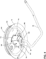
- the gas burner 10 for a cooktop 78 has a gas inlet 94 that supplies fuel to the burner 10 through an injector orifice 98 at its terminal end 102.
- the injector orifice 98 is secured in position below a cooktop aperture 106 with a bracket 110 that is fastened to an underside 114 of the cooktop 78.
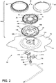
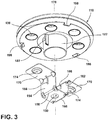
- a burner assembly 118 includes a gas flow path through a stem 122 (shown in FIG. 3 ), a venturi tube 126, a mixing chamber 130, fuel exit ports 30, and the combustion chamber 18.
- Fuel is supplied to the burner 10 through the gas inlet 94.
- Primary air is introduced to the venturi tube 126 to form a combustible gas-primary air mixture in the mixing chamber 130.
- the gas-primary air mixture is then expelled through the plurality of fuel exit ports 30 into the combustion chamber 18, where a spark electrode 134 is disposed to ignite the gas-primary air mixture.
- Secondary air inlets 138 extend from the combustion chamber 18 to ambient air outside the burner assembly 118, allowing secondary air to be drawn into the combustion chamber 18 by convection to encourage complete combustion.
- the burner assembly 118 as depicted in the embodiment of FIG. 2 includes the burner base 34, swirl spreader 38, and the annular burner cap set 46, which define the functional elements of the stem 122, venturi tube 126, mixing chamber 130, plurality of fuel exit ports 30, and the combustion chamber 18. Although shown as three parts that are assembled to form the burner assembly 118 in the embodiment depicted in FIG.
- the functional elements of the burner assembly 118 may be constructed out of more or less assembled parts, and may be integrally formed in a single piece, if desired.
- the annular burner cap set 46 includes both the inner flame burner cap 50 and the vertical flame burner cap 54.
- the inner flame burner cap 50 and the vertical flame burner cap 54 may be a variety of other shapes, for example a radial, circular, oval, square, or triangular shape so that it can be positioned on the top portion 42 of the circumferential crenellated wall 26.
- the bracket 110 used to secure the gas inlet 94 includes an orifice-securing surface 146 with a hole 150 therethrough for passage of the gas inlet 94, with the injector orifice 98 held in place above the orifice-securing surface 146.
- the orifice-securing surface 146 shown herein is generally planar and parallel to the underside 114 of the cooktop 78, and is generally square or rectangular shaped. Alternate embodiments may include alternate designs of the orifice-securing surface 146, including without limitation curved edges, a non-planar shape, a slot for passage of the gas inlet 94, etc.
- a first sidewall 154 extends upwardly from a first edge 158 of the orifice-securing surface 146, and a second sidewall 162 extends upwardly from a second edge 166 of the orifice-securing surface 146.
- Each sidewall 154, 162 terminates in a outwardly directed fastening flange 170.
- the fastening flanges 170 have through holes 174 therethrough, for fastening the bracket 110 to the cooktop 78 with the fastening flanges 170 on opposing sides of the cooktop aperture 106.
- the first sidewall 154 and second sidewall 162 are separated by a distance which is less than the diameter of the cooktop aperture 106, resulting in a portion of each of the fastening flanges 170 being aligned below the cooktop aperture 106.
- the bracket 110 is secured to the cooktop 78 by positioning it below the cooktop 78 and fastening the bracket 110 to the underside 114 thereof using fasteners (not shown).
- the bracket 110 when installed, positions the injector orifice 98 generally in the center of the cooktop aperture 106, and, therefore, along a central axis 178 of the gas burner 10.
- the burner assembly 118 is removably secured to the bracket 110 in the desired orientation by aligning a plurality of tabs 182 extending outwardly from the stem 122 with slots 186 that extend through the fastening flanges 170 and sidewalls 154, 162 of the bracket 110, such that the burner assembly 118 is properly aligned with the injector orifice 98.
- the injector orifice 98 directs the flow of fuel upward into the stem 122 and venturi tube 126.
- the slots 186 and the bracket 110 are asymmetrically arranged, with two slots 186 on the first sidewall 154 of the bracket 110 and one slot 186 on the second sidewall 162 of the bracket 110, and a corresponding tab 182 on the side of the stem 122 and one tab 182 on an opposing side of the stem 122.
- the asymmetrical alignment allows the burner assembly 118 to be secured to the bracket 110 in a single orientation, and prevents the use of alternate burner assemblies that are not optimized for use with the particular injector orifice 98 used.
- the particular asymmetrical arrangement of slots 186 and tabs 182 can be used to ensure that alternate burner assemblies are not installed into the cooking aperture 106.
- the secondary air inlets 138 extend from the combustion chamber 18, through the mixing chamber 130 to ambient air.
- the secondary air inlets 138 permit the inflow of secondary air to enhance combustion characteristics of the burner 10.
- the secondary air inlets 138 include downwardly depending cylinders 190 which extend from the swirl spreader 38 to apertures 194 in the burner base 34, to create a channel for the flow of secondary air through the mixing chamber 130 (where the secondary air is fluidly separated from the mixing chamber 130).
- the number of secondary air inlets 138 and their cross-sectional area can be varied to provide desired burner characteristics for the gas burner 10. In the embodiment depicted in FIGS.
- the burner assembly 118 has its combustion chamber 18 partially defined by the bottom 22, the circumferential crenellated wall 26, and the plurality of fuel exit ports 30.
- One or more secondary air inlets 138 may be formed in the bottom 22 of the combustion chamber 18, and they may be evenly spaced about the circumference of the bottom 22 of the combustion chamber 18.
- the venturi tube 126 FIG. 2
- the venturi tube 126 has a venturi tube cover 202 that may have a plurality of venturi tube ornamental marks 206 covering it.
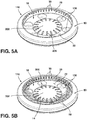
- FIG. 5B depicts the inner flame state 58 where the flames are directed inwardly to the combustion chamber 18 by the inner flame burner cap 50.
- switchable flame 14 collectively refers to both the inner flame state 58 and the vertical flame state 62 where the flame can be switched between the inner flame state 58 produced by the inner flame burner cap 50 and the vertical flame state 62 produced by the vertical flame burner cap 54 at any time as determined by the user.
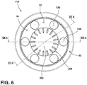
- FIG. 6 depicts a top view of the burner assembly 118 with the combustion chamber 18 having its bottom 22 and secondary air inlets 138 encircling the venturi tube cover 202 with its plurality of venturi tube ornamental marks 206.
- the top view of the burner assembly 118 additionally illustrates the inner flame burner cap 50 covering the top portion 42 of the circumferential crenellated wall 26 (not shown) of the burner assembly 118.
- FIGS. 7A-7B a cross-sectional view of the burner assembly 118 is shown to demonstrate the flow of the fuel 210 throughout the gas burner 10.
- the fuel 210 flows upward through the venturi tube 126 enclosed by the stem 122 wherein the fuel 210 then flows up against the venturi tube cover 202 and flows out across a bottom plate 212 out against a peripheral wall 214 and out through the plurality of fuel exit ports 30 as directed by the inner flame burner cap 50 positioned on top of the circumferential crenellated wall 26.
- the inner flame burner cap 50 has an outer cap wall 218, an annular wall 222, and a top cap wall 226 that direct the flow of fuel 210 through the plurality of fuel exit ports 30 into the combustion chamber 18 (not shown) of the burner assembly 118.
- At least one secondary air inlet 138 is shown to encourage complete combustion in combustion chamber 18.
- the outer cap wall 218 slides down along the peripheral wall 214 to leave a small gap between the outer cap wall 218 and a ledge member 220.
- a spreader assembly 140 includes both the swirl spreader 38 and the burner base 34 upon which the inner flame burner cap 50 is positioned.
- the outer cap wall 218 couples to a back edge 228 of the peripheral wall 214 of the burner base 34.
- the plurality of fuel exit ports 30 in the circumferential crenellated wall 26 direct the fuel 210 in both an inwardly and upwardly directed swirling configuration.
- the user may selectively use the inner flame state 58 or the vertical flame state 62.
- the inner flame burner cap 50 is coupled to the swirl spreader 38 to block the fuel exit ports 30 directed generally upwardly from the bottom 22 of the combustion chamber 18.
- the inner flame burner cap 50 blocks the fuel exit ports 30 directed generally upwardly from the bottom 22 of the combustion chamber 18 with its annular wall 222.
- the fuel 210 is then directed inwardly towards the combustion chamber 18 to form the inner flame state 58 once the fuel 210 is ignited.
- the plurality of fuel exit ports 30 are directed inwardly at an angle that is slightly rotated from the central axis or radial line 178 through a center of the gas burner 10 to create the inner flame state 58.
- the inner flame burner cap 50 includes the inner flame burner cap 50 positioned on top of the spreader assembly 140, where it encloses the top of the mixing chamber 130 between the peripheral wall 214 of the burner base 34. and the circumferential crenelated wall 26 of the swirl spreader 38.
- the inner flame burner cap 50 also encloses the top 234 of the channels 230, to direct the flow of fuel 210 inwardly toward the combustion chamber 18.
- the inner flame burner cap 50 is optionally shaped and has a diameter 238 that extends the outer burner cap wall 218 over a portion of the peripheral wall 214 of the burner base 34, to retain the inner flame burner cap 50 in position.
- the inner flame burner cap 50 may also be constructed of any material suitable for use in burner caps, including without limitation a suitable polished brass alloy, iron, or a steel material formed by stamping and sintering metal powder.
- the fuel 210 is supplied to the gas burner 10 through the gas inlet 94, and is sprayed through the gas injector orifice 98, into the stem 122.
- the fuel 210 then travels through the venturi tube 126, where primary air is introduced.
- the gas and primary air are expelled into the mixing chamber 130, which is defined by the burner base 34, the swirl spreader 38, and the inner flame burner cap 50.
- the gas and primary air mixture is then forced through the plurality of fuel exit ports 30 by pressure in the mixing chamber 130, into the combustion chamber 18.
- the plurality of fuel exit ports 30 direct the gas in an inwardly and upwardly directed swirling configuration.
- the gas-primary air mixture is ignited in the combustion chamber 18 by the spark electrode 134, and the swirling upwardly directed flame causes secondary air to enter the combustion chamber 18 through the secondary air inlets 138 in the bottom of the combustion chamber 18 by convection to encourage complete combustion.
- the gas burner 10 disclosed herein using the inner flame burner cap 50 provides several advantages. For example, cookware placed on the inner flame burner cap 50 is heated effectively and efficiently by the swirling inwardly directed flames, with limited heat loss around the exterior of the cookware. Efficiencies of 60% or greater are possible with the inwardly swirling directed flames as described herein. The inwardly directed flames also reduced the risk of a user being burned by the flames, as they are directed to be underneath the cookware. Additionally, the embodiments described herein are resistant to spillage, without openings or holes facing the top of the gas burner 10 where cookware is placed. The aesthetics of the gas burner 10 are improved due to the smooth, uninterrupted viewable surface.
- the gas burner 10 described herein can also be removed from the cooktop 78 without disconnecting the injector orifice 98, which is secured using the bracket 110, and replaced in a proper orientation using the asymmetrically arranged tabs 182 and slots 186 described herein.
- the burner assembly 118 has its combustion chamber 18 partially defined by the bottom 22, and the circumferential crenellated wall 26 with its plurality of fuel exit ports 30 covered by the vertical flame burner cap 54.
- One or more secondary air inlets 138 may be formed in the bottom 22 of the combustion chamber 18, and they may be evenly spaced about the circumference of the bottom 22 of the combustion chamber 18.
- the venturi tube 126 has a venturi tube cover 202 that may have the plurality of venturi tube ornamental marks 206 covering it.
- the vertical flame burner cap 54 is coupled to the swirl spreader 38 of the circumferential crenellated wall 26 and the vertical flame burner cap 54 blocks the plurality of fuel exit ports 30 directed generally inwardly to route the fuel 210 upwardly to produce the vertical flame state 62.
- FIG. 5B depicts the vertical flame state 62 that is directed upwardly away from the burner assembly 118 through one or more flame apertures 250 in the vertical flame burner cap 54.
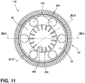
- FIG. 11 depicts a top view of the burner assembly 118 with the combustion chamber 18 having its bottom 22 and secondary air inlets 138 encircling the venturi tube cover 202 with its plurality of venturi tube ornamental marks 206.
- the top view of the burner assembly 118 additionally illustrates the vertical flame burner cap 54 covering the circumferential crenellated wall 26 of the burner assembly 118.
- FIGS. 12A-12B a cross-sectional view of the burner assembly 118 is shown to demonstrate the flow of fuel 210 throughout the gas burner 10.
- the fuel 210 flows upward through the venturi tube 126 enclosed by the stem 122 where the fuel flows up against the venturi tube cover 202 and flows out across the bottom plate 212 out against the peripheral wall 214 and up through the plurality of fuel exit ports 30 as directed by the vertical flame burner cap 54 positioned on top of the circumferential crenellated wall 26.
- the vertical flame burner cap 54 has an outer cap wall 254, a perforated annular wall 262, and an inner cap wall 258 that direct the flow of fuel 210 through the plurality of fuel exit ports 30 upwardly away from the burner assembly 118.
- At least one secondary air inlet 138 is shown to assist in the production of the gas-primary air mixture.
- the vertical burner outer cap wall 254 slides down along the peripheral wall 214 to leave a small gap between the outer cap wall 218 and the ledge member 220.
- the spreader assembly 140 includes both the swirl spreader 38 and the burner base 34 upon which the vertical flame burner cap 54 is positioned.
- the vertical burner annular wall 262 is perforated with at least one flame aperture 250 for directing fuel 210 in the vertical flame state 62.
- the flame apertures 250 of the vertical flame burner cap 54 have a diameter from 1.50 mm to 2.25 mm, an area from 2.25 mm 2 to 3.25 mm 2 , and from 250 to 350 flame apertures.
- the flame apertures 250 in the vertical flame burner cap 54 have a diameter from 1.50 mm to 2.00 mm, 1.75 mm to 2.25 mm, 1.70 mm to 1.90 mm, about 1.70 mm, 1.75 mm, 1.80 mm, or about 1.85 mm.
- the flame apertures 250 in the vertical flame burner cap 54 have an area from 2.25 mm 2 to 3.25mm 2 , 2.50 mm 2 to 3.00 mm 2 , 2.50 mm 2 to 2.75mm 2 , 2.65 mm 2 to 3.85 mm 2 , about 2.60 mm 2 , about 2.65 mm 2 , about 2.70 mm 2 , about 2.75 mm 2 , or about 2.80 mm 2 .
- the vertical flame burner cap 54 has from 250 to 350 flame apertures, from 275 to 325 flame apertures, from 275 to 300 flame apertures, or about 275 flame apertures, about 280 flame apertures, about 285 flame apertures, about 290 flame apertures, or about 295 flame apertures.
- the arrangement of flame apertures 250 may be spaced around the circumference of the vertical burner annular wall 262.
- the vertical burner annular wall 262 has three rings of 95 flame apertures 250 with about 4.27 mm space between the flame apertures 250 on the outer ring, 4.15 mm of space between the flame apertures 250 on the middle ring, and 3.97 mm of space between the flame apertures 250 on the inner ring.
- the configuration of the flame apertures 250 around the circumference of the vertical burner annular wall 262 may be orientated in any given manner, for example, one or more flame apertures 250 may be positioned in a radial, circular, oval, square, or triangular orientation around the vertical burner annular wall 262.
- the flame apertures 250 may be shaped in any geometry, for example, a cylindrical shape, a conical shape, a cubical shape, or a star shape.
- the vertical flame burner cap 54 is coupled to the swirl spreader 38 to block the plurality of fuel exit ports 30 directed generally inwardly toward the combustion chamber 18.
- the vertical flame burner cap 54 has an internal cap diameter 266 having a first inner edge 274 and an outer cap diameter 270 having a second inner edge 278 where the first inner edge 274 couples to a front edge 224 of the circumferential crenulated wall 26 and the second inner edge 278 couples to the back edge 228 of the peripheral wall 214 of the burner base 34 wherein the vertical flame burner cap 54 extends over the circumferential crenellated wall 26 and the peripheral wall 214 of the burner base 34.
- the vertical flame burner cap 54 includes the vertical flame burner cap 54 positioned on top of the spreader assembly 140, where it encloses the top of the mixing chamber 130 between the peripheral wall 214 of the burner base 34 and the circumferential crenelated wall 26 of the swirl spreader 38.
- the vertical flame burner cap 54 also encloses the top 234 of the channels 230, to direct the flow of fuel 210 upwardly away from the burner assembly 118.
- the vertical flame burner cap 54 is optionally shaped and has the vertical burner outer wall 254 designed to extend over a portion of the peripheral wall 214 of the burner base 34 and pushed down against the ledge member 220 to retain the vertical flame burner cap 54 in position.
- the vertical flame burner cap 54 additionally has the vertical burner inner wall 258 blocking the inwardly flow of fuel 210 through the plurality of fuel exit ports 30 to redirect the flow of fuel 210 upwardly away from the burner assembly 118 to give the vertical flame state 62.
- the vertical flame burner cap 54 may also be constructed of any material suitable for use in burner caps, including without limitation a suitable polished brass alloy, iron, or a steel material formed by stamping and sintering metal powder.
- the fuel 210 is supplied to the gas burner 10 through the gas inlet 94, and is sprayed through the gas injector orifice 98, into the stem 122.
- the fuel 210 then travels through the venturi tube 126, where primary air is introduced.
- the gas and primary air are expelled into the mixing chamber 130, which is defined by the burner base 34, the swirl spreader 38, and the vertical flame burner cap 54.
- the gas and primary air mixture is then forced through the plurality of fuel exit ports 30 by pressure in the mixing chamber 130, into the combustion chamber 18.
- the plurality of fuel exit ports 30 direct the gas in an inwardly and upwardly directed swirling configuration.
- the gas-primary air mixture is ignited in the combustion chamber 18 by the spark electrode 134, and the upwardly swirling directed flame through the flame apertures 250 causes secondary air to enter the combustion chamber 18 through the secondary air inlets 138 in the bottom of the combustion chamber 18 by convection to encourage complete combustion.
- the gas burner 10 disclosed herein provides several advantages. For example, cookware placed on the gas burner 10 is heated effectively and efficiently by the swirling inwardly directed flames, with limited heat loss around the exterior of the cookware. Efficiencies of 60% or greater are possible with the vertically projected flames as described herein. The upwardly or vertically directed flames are directed underneath the cookware for a more direct heating source. The aesthetics of the gas burner 10 are improved due to the smooth, uninterrupted viewable flame surface.
- the vertical flame burner cap 54 described herein can be removed from the burner assembly 118 without disconnecting the swirl spreader 38 from the burner base 34, and replaced in a proper orientation using the asymmetrically arranged tabs 182 and slots 186 described herein.
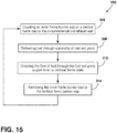
- a method 300 for converting between the inner flame state 58 and the vertical flame state 62 of the gas burner 10 includes, coupling one of the inner flame burner cap 50 and the vertical flame burner cap 54 to the top portion 42 of the circumferential crenellated wall 26 to selectively and alternatively define the inner flame state 58 and the vertical flame state 62 (step 304); delivering the fuel 210 through the plurality of fuel exit ports 30 in the circumferential crenellated wall 26 (step 308); redirecting the flow of fuel 210 from the fuel exit ports 30 indicative of one of the inner flame state 58 and the vertical flame state 62, alternatively (step 312); and removing the inner flame burner cap 50 or the vertical flame burner cap 54 (step 316).
- the inner flame burner cap 50 or the vertical flame burner cap 54 is previously coupled, removing the inner flame burner cap 50 if the vertical flame state 62 is selected or removing the vertical flame burner cap 54 if the inner flame state 58 is selected (step 316). In other embodiments, again determining if the alternative inner flame state 58 or vertical flame state 62 is desired and repeated steps 304, 308, 312 after removing the cap 50, 54 previously coupled.
- the method 300 can be repeated an indefinite number of times to repeated switch back and forth between the inner flame state 58 and the vertical flame state 62 as desired by the user.
- the term "coupled” in all of its forms, couple, coupling, coupled, etc. generally means the joining of two components (electrical or mechanical) directly or indirectly to one another. Such joining may be stationary in nature or movable in nature. Such joining may be achieved with the two components (electrical or mechanical) and any additional intermediate members being integrally formed as a single unitary body with one another or with the two components. Such joining may be permanent in nature or may be removable or releasable in nature unless otherwise stated.
- elements shown as integrally formed may be constructed of multiple parts or elements shown as multiple parts may be integrally formed, the operation of the interfaces may be reversed or otherwise varied, the length or width of the structures and/or members or connector or other elements of the system may be varied, the nature or number of adjustment positions provided between the elements may be varied.
- the elements and/or assemblies of the system may be constructed from any of a wide variety of materials that provide sufficient strength or durability, in any of a wide variety of colors, textures, and combinations. Accordingly, all such modifications are intended to be included within the scope of the present innovations. Other substitutions, modifications, changes, and omissions may be made in the design, operating conditions, and arrangement of the desired and other exemplary embodiments without departing from the spirit of the present innovations.
- Embodiment A is a gas burner with a switchable flame comprising: a combustion chamber having a bottom and a circumferential crenellated wall; a plurality of fuel exit ports disposed in the circumferential crenellated wall, the fuel exit ports directed generally inwardly toward the combustion chamber and upwardly from the bottom of the combustion chamber; a swirl spreader disposed above a burner base which defines a top portion of the circumferential crenellated wall of the combustion chamber; and an annular burner cap set that includes an inner flame burner cap and a vertical flame burner cap.
- the inner flame burner cap and the vertical flame burner cap are selectively and alternatively positioned on the crenellated wall to define an inner flame state and a vertical flame state, respectively, of the fuel exit ports.
- the gas burner of Embodiment A wherein the vertical flame burner cap includes a perforated annular wall having at least one flame aperture for directing fuel in the vertical flame state and wherein the inner flame burner cap includes a solid annular wall for directing fuel in the inner flame state.
- the vertical flame burner cap has an internal cap diameter with a first inner edge and an outer cap diameter with a second inner edge that couple to a front edge of the circumferential crenellated wall and a back edge of a peripheral wall of a burner base wherein the vertical flame burner cap extends over the circumferential crenellated wall and the peripheral wall.
- Embodiment B is a method for converting between an inner flame state and a vertical flame state of a gas burner comprising the steps: coupling one of an inner flame burner cap and a vertical flame burner cap to a top portion of a circumferential crenellated wall to selectively and alternatively define an inner burner state and a vertical burner state; delivering a flow of fuel through a plurality of fuel exit ports in the circumferential crenellated wall; and redirecting the flow of fuel from the fuel exit ports indicative of one of the inner flame state and the vertical flame state, alternatively.
- Embodiment B wherein the inner flame cap and the vertical flame cap can be installed and removed from the crenellated wall by hand and without the use of tools.
- Embodiment B or Embodiment B with any of the intervening features further comprising the step: if previously coupled, removing the inner flame burner cap if the vertical flame state is selected or removing the vertical flame burner cap if the inner flame state is selected.
- Embodiment B or Embodiment B with any of the intervening features wherein the vertical flame burner cap is coupled to a swirl spreader to partially block the plurality of fuel exit ports to be directed generally inwardly toward a combustion chamber.
- Embodiment B or Embodiment B with any of the intervening features wherein the vertical flame burner cap is coupled to a swirl spreader to partially block the plurality of fuel exit ports to be directed generally inwardly toward a combustion chamber.
- Embodiment B or Embodiment B with any of the intervening features wherein the inner flame burner cap is coupled to a swirl spreader to partially block the plurality of fuel exit ports to be directed generally upwardly from the bottom of a combustion chamber.
- Embodiment B or Embodiment B with any of the intervening features wherein the fuel exit ports are directed inwardly at an angle that is slightly rotated from a radial line through the center of the burner to create the inner flame.
- Embodiment C is a flame diverter set for a gas burner comprising: a combustion chamber having a bottom and a circumferential crenellated wall; a plurality of fuel exit ports disposed in the circumferential crenellated wall, the plurality of fuel exit ports directed generally inwardly toward the combustion chamber and upwardly from the bottom of the combustion chamber; and a burner base.
- the flame diverter set for a gas burner further comprises an inner flame burner cap selectively and alternatively coupled to a top portion of the circumferential crenellated wall that defines the plurality of fuel exit ports directed generally inwardly toward the combustion chamber to create an inner flame state projected into the combustion chamber; and a vertical flame burner cap selectively and alternatively coupled to the top portion of the circumferential crenellated wall that defines a plurality of fuel exit ports directed generally upwardly to create the vertical flame state projected up from the gas burner, the vertical flame state being selectively alternative to the inner flame state.
- the flame diverter set of Embodiment C wherein the vertical flame burner cap includes a perforated annular wall having at least one flame aperture for directing fuel in the vertical flame state and wherein the inner flame burner cap includes a solid annular wall for directing fuel in the inner flame state.
- the flame diverter set of Embodiment C or Embodiment C with any of the intervening features wherein the vertical flame burner cap has an internal cap diameter with a first inner edge and an outer cap diameter with a second inner edge that couple to a front edge of the circumferential crenellated wall and a back edge of a peripheral wall of a burner base wherein the vertical flame burner cap extends over the circumferential crenellated wall and the peripheral wall.
- Embodiment C The flame diverter set of Embodiment C or Embodiment C with any of the intervening features wherein the vertical flame burner cap is coupled to a swirl spreader to partially block the fuel exit ports to be directed generally inwardly toward the combustion chamber.
- Embodiment C The flame diverter set of Embodiment C or Embodiment C with any of the intervening features wherein the inner flame burner cap is coupled to a swirl spreader to partially block the fuel exit ports to be directed generally upwardly from the bottom of the combustion chamber.
Landscapes
- Engineering & Computer Science (AREA)
- Chemical & Material Sciences (AREA)
- Combustion & Propulsion (AREA)
- Mechanical Engineering (AREA)
- General Engineering & Computer Science (AREA)
- Gas Burners (AREA)
Applications Claiming Priority (1)
| Application Number | Priority Date | Filing Date | Title |
|---|---|---|---|
| US15/287,147 US10436451B2 (en) | 2016-10-06 | 2016-10-06 | Cap to change inner flame burner to vertical flame |
Publications (2)
| Publication Number | Publication Date |
|---|---|
| EP3306192A1 true EP3306192A1 (de) | 2018-04-11 |
| EP3306192B1 EP3306192B1 (de) | 2020-04-22 |
Family
ID=60037434
Family Applications (1)
| Application Number | Title | Priority Date | Filing Date |
|---|---|---|---|
| EP17195087.6A Active EP3306192B1 (de) | 2016-10-06 | 2017-10-06 | Kappe zum verändern eines innenflammenbrenners zur vertikalen flamme |
Country Status (2)
| Country | Link |
|---|---|
| US (2) | US10436451B2 (de) |
| EP (1) | EP3306192B1 (de) |
Cited By (2)
| Publication number | Priority date | Publication date | Assignee | Title |
|---|---|---|---|---|
| EP3809041A1 (de) * | 2019-10-18 | 2021-04-21 | Whirlpool Corporation | Gaskochfeldbrenneranordnung |
| CN113531529A (zh) * | 2020-04-16 | 2021-10-22 | 林内株式会社 | 炉灶用燃烧器及燃气灶 |
Families Citing this family (8)
| Publication number | Priority date | Publication date | Assignee | Title |
|---|---|---|---|---|
| EP3056810B1 (de) * | 2015-02-11 | 2019-04-10 | Electrolux Appliances Aktiebolag | Gasbrenneranordnung |
| US10436451B2 (en) * | 2016-10-06 | 2019-10-08 | Whirlpool Corporation | Cap to change inner flame burner to vertical flame |
| CN108413398A (zh) * | 2018-05-31 | 2018-08-17 | 宿元凯 | 一种聚热催化型多头燃烧器 |
| US11549688B2 (en) * | 2019-04-22 | 2023-01-10 | Whirlpool Corporation | Anti-rotation feature for a burner |
| US11460190B2 (en) * | 2019-07-29 | 2022-10-04 | Haier Us Appliance Solutions, Inc. | Gas burner assembly for a cooktop appliance |
| CN110410792B (zh) * | 2019-08-30 | 2021-02-26 | 宁波方太厨具有限公司 | 灶具火盖 |
| US11680711B2 (en) | 2021-08-03 | 2023-06-20 | Haier Us Appliance Solutions, Inc. | Vortex shield for a gas burner |
| BR102021018934A2 (pt) * | 2021-09-22 | 2023-04-04 | Electrolux Appliances Aktiebolag | Queimador tubular de gás |
Citations (3)
| Publication number | Priority date | Publication date | Assignee | Title |
|---|---|---|---|---|
| US20110086318A1 (en) * | 2009-10-09 | 2011-04-14 | American Wyott Corporation | Method and apparatus for maintaining stable flame conditions in a gas burner |
| EP2799771A2 (de) * | 2013-04-29 | 2014-11-05 | Indesit Company S.p.A. | Gasbrenner, insbesondere für Kochgerät |
| US20150040887A1 (en) * | 2013-08-06 | 2015-02-12 | Whirlpool Corporation | Inner swirling flame gas burner |
Family Cites Families (50)
| Publication number | Priority date | Publication date | Assignee | Title |
|---|---|---|---|---|
| US794545A (en) | 1905-04-14 | 1905-07-11 | Thomas W Phillips Jr | Fuel-burner. |
| FR400388A (fr) | 1908-06-03 | 1909-07-26 | Michel Kouzmine | Perfectionnements aux bruleurs des fourneaux à gaz |
| US1376241A (en) | 1920-03-02 | 1921-04-26 | Rollo Marple | Gas-burner attachment |
| US2037603A (en) | 1934-06-19 | 1936-04-14 | Emanuel J Sonn | Safety plate for gas burners |
| US2410547A (en) | 1942-04-03 | 1946-11-05 | Mccollum Thelma | Heating apparatus |
| US2805710A (en) | 1951-03-13 | 1957-09-10 | Brumbaugh Isaac Vernon | Gas burner |
| JPS5630521A (en) | 1979-08-21 | 1981-03-27 | Shoei Seisakusho:Kk | Swirl combustion type gas burner |
| IL66538A (en) | 1982-08-13 | 1985-07-31 | Univ Ben Gurion | Burner for gaseous fuel |
| IT1250838B (it) | 1991-09-26 | 1995-04-21 | Merloni Elettrodomestici Spa | Bruciatore di gas. |
| DE4203668A1 (de) | 1992-02-08 | 1993-08-12 | Elektro Gas Armaturen | Gasbrenner |
| US5437262A (en) | 1994-02-17 | 1995-08-01 | Gas Research Institute | Burner apparatus |
| US6299436B1 (en) * | 1997-10-20 | 2001-10-09 | Bsh Home Appliances Corporation | Plurality fingered burner |
| IT1318126B1 (it) * | 2000-07-06 | 2003-07-23 | Sabaf Spa | Bruciatore con separatore interno |
| JP3691447B2 (ja) | 2002-03-20 | 2005-09-07 | リンナイ株式会社 | バーナ |
| JP3691448B2 (ja) | 2002-03-22 | 2005-09-07 | リンナイ株式会社 | バーナ |
| US6619280B1 (en) | 2002-05-30 | 2003-09-16 | Dongsheng Zhou | Converging flame burner |
| FR2848642B1 (fr) | 2002-12-17 | 2005-08-05 | Service Nat Dit Gaz De France | Bruleur a gaz a flamme interne, de compacite elevee |
| EP2258981B1 (de) | 2003-09-05 | 2018-07-25 | Electrolux Home Products Corporation N.V. | Gasbrenner |
| US20050277079A1 (en) | 2004-06-15 | 2005-12-15 | Tsen-Tung Wu | Gas burner |
| US20050277080A1 (en) | 2004-06-15 | 2005-12-15 | Tsen-Tung Wu | Gas burner |
| US20060024632A1 (en) | 2004-07-29 | 2006-02-02 | Sanchez Jairo E | Gas burner head with extra simmer, burner base assembly and combination thereof |
| FR2875583B1 (fr) | 2004-09-17 | 2007-04-13 | Lemdys Soc Par Actions Simplif | Bruleur a gaz a flamme interne perfectionne |
| JP2006098001A (ja) | 2004-09-30 | 2006-04-13 | Asahi Seisakusho Co Ltd | 内炎式バーナ |
| US20060147865A1 (en) | 2005-01-05 | 2006-07-06 | Charles Czajka | Cooking range burner head assembly |
| US20100154776A1 (en) | 2005-01-05 | 2010-06-24 | Charles Czajka | Cooking range burner head assembly |
| FR2889293B1 (fr) | 2005-07-29 | 2009-12-18 | Burner Systems Int Bsi | Bruleur a gaz a multiples couronnes de flammes concentriques |
| US7942143B2 (en) | 2006-12-20 | 2011-05-17 | Lg Electronics Inc. | Heating cooking appliance and burner system thereof |
| ITTO20070133A1 (it) | 2007-02-26 | 2008-08-27 | Indesit Co Spa | Sistema di bruciatori di gas per apparecchi di cottura per alimenti |
| ITMC20070130A1 (it) | 2007-06-28 | 2008-12-29 | Somi Press Soc Metalli Iniettati Spa | Doppio bruciatore, di tipo perfezionato, per fornelli a gas a piu' corone di fiamme. |
| US8171927B2 (en) | 2007-09-27 | 2012-05-08 | Electrolux Home Products, Inc. | Burner cap flame stabilization chamber |
| EP2072895B1 (de) | 2007-12-18 | 2014-07-23 | Electrolux Home Products Corporation N.V. | Gasbrenner mit verbesserter primärer Luftleitung |
| ES2389998T3 (es) | 2008-03-25 | 2012-11-05 | Electrolux Home Products Corporation N.V. | Encimera de cocción con quemador de gas mejorado |
| US8616193B2 (en) * | 2008-06-27 | 2013-12-31 | Electrolux Home Products, Inc. | Cooktop swirl burner |
| CN101737782B (zh) * | 2008-11-21 | 2012-08-29 | 博西华电器(江苏)有限公司 | 燃气灶炉头火盖及带有该种火盖的炉头 |
| PT2359061T (pt) | 2008-12-12 | 2018-11-29 | Sabaf Spa | Queimador a gás para fogões domésticos |
| US8689779B2 (en) | 2009-01-23 | 2014-04-08 | Bsh Bosch Und Siemens Hausgeraete Gmbh | Gas burner |
| US8973569B2 (en) * | 2009-02-18 | 2015-03-10 | Electrolux Home Products, Inc. | Gas burner |
| ES2552547T3 (es) | 2009-04-30 | 2015-11-30 | Electrolux Home Products Corporation N.V. | Quemador de llama vertical |
| AU2010324618B2 (en) | 2009-11-30 | 2014-11-13 | Electrolux Home Products, Inc. | Simmer plate attached to burner |
| US8899972B2 (en) * | 2009-12-14 | 2014-12-02 | Electrolux Home Products, Inc. | Burner designed for wide range of input rates |
| MX345335B (es) * | 2009-12-18 | 2017-01-25 | Mabe S A De C V * | Quemador de tres sectores de flama. |
| CN102439360B (zh) | 2010-06-30 | 2015-08-19 | 萨巴夫股份有限公司 | 燃气炉具 |
| ITAN20120036A1 (it) | 2011-04-19 | 2012-10-20 | Somipress Societa Metalli Iniett Ati S P A | Fornello a gas con fiamma rivolta verso l'interno. |
| MX337534B (es) | 2011-10-14 | 2016-03-09 | Mabe Sa De Cv | Quemador delta. |
| ITAN20120142A1 (it) | 2011-11-04 | 2013-05-05 | Somipress Societa Metalli Iniett Ati S P A | Fornello a gas con fiamma rivolta verso l'interno. |
| BRPI1105194A2 (pt) | 2011-12-21 | 2013-11-19 | Whirlpool Sa | Queimador para equipamentos de cocção |
| PL2791579T3 (pl) * | 2012-10-26 | 2016-12-30 | Palnik gazowy | |
| US20150107577A1 (en) * | 2013-10-18 | 2015-04-23 | Lg Electronics Inc. | Burner |
| USD794545S1 (en) | 2016-01-11 | 2017-08-15 | The Goodyear Tire & Rubber Company | Tire |
| US10436451B2 (en) | 2016-10-06 | 2019-10-08 | Whirlpool Corporation | Cap to change inner flame burner to vertical flame |
-
2016
- 2016-10-06 US US15/287,147 patent/US10436451B2/en active Active
-
2017
- 2017-10-06 EP EP17195087.6A patent/EP3306192B1/de active Active
-
2019
- 2019-08-29 US US16/555,294 patent/US11421889B2/en active Active
Patent Citations (3)
| Publication number | Priority date | Publication date | Assignee | Title |
|---|---|---|---|---|
| US20110086318A1 (en) * | 2009-10-09 | 2011-04-14 | American Wyott Corporation | Method and apparatus for maintaining stable flame conditions in a gas burner |
| EP2799771A2 (de) * | 2013-04-29 | 2014-11-05 | Indesit Company S.p.A. | Gasbrenner, insbesondere für Kochgerät |
| US20150040887A1 (en) * | 2013-08-06 | 2015-02-12 | Whirlpool Corporation | Inner swirling flame gas burner |
Cited By (3)
| Publication number | Priority date | Publication date | Assignee | Title |
|---|---|---|---|---|
| EP3809041A1 (de) * | 2019-10-18 | 2021-04-21 | Whirlpool Corporation | Gaskochfeldbrenneranordnung |
| CN113531529A (zh) * | 2020-04-16 | 2021-10-22 | 林内株式会社 | 炉灶用燃烧器及燃气灶 |
| CN113531529B (zh) * | 2020-04-16 | 2025-09-02 | 林内株式会社 | 炉灶用燃烧器及燃气灶 |
Also Published As
| Publication number | Publication date |
|---|---|
| US10436451B2 (en) | 2019-10-08 |
| EP3306192B1 (de) | 2020-04-22 |
| US20180100655A1 (en) | 2018-04-12 |
| US11421889B2 (en) | 2022-08-23 |
| US20190383492A1 (en) | 2019-12-19 |
Similar Documents
| Publication | Publication Date | Title |
|---|---|---|
| US11421889B2 (en) | Cap to change inner flame burner to vertical flame | |
| US10731851B2 (en) | Inner swirling flame gas burner | |
| EP2140200B1 (de) | Verbesserter gasbrenner für kochgeräte | |
| US8899972B2 (en) | Burner designed for wide range of input rates | |
| US7017572B2 (en) | Method and apparatus for gas ranges | |
| US20180209657A1 (en) | Diffusion cap burner for gas cooking appliance | |
| EP3094925B1 (de) | Gasbrenner für kochfeld | |
| US10145568B2 (en) | High efficiency high power inner flame burner | |
| EP3343104B1 (de) | Verteilter vertikalflammenbrenner | |
| US9677768B2 (en) | Multi-ring gas burner | |
| EP3268667B1 (de) | Verbesserter gasbrenner | |
| US20190331337A1 (en) | Gas burner and hob comprising a gas burner | |
| US20060147865A1 (en) | Cooking range burner head assembly | |
| US20180142901A1 (en) | Gas burner assembly for a cooktop appliance | |
| US20170038076A1 (en) | Gas burner, in particular for a cooking top for household use | |
| JP4103114B2 (ja) | バーナ装置 | |
| WO2007068659A1 (en) | A cooking device | |
| EP2868968A1 (de) | Brenner mit mehreren Brennringe | |
| EP3748230B1 (de) | Gasbrenneranordnung | |
| JP4452879B2 (ja) | コンロ | |
| HK1177490A (en) | Gas stove |
Legal Events
| Date | Code | Title | Description |
|---|---|---|---|
| PUAI | Public reference made under article 153(3) epc to a published international application that has entered the european phase |
Free format text: ORIGINAL CODE: 0009012 |
|
| STAA | Information on the status of an ep patent application or granted ep patent |
Free format text: STATUS: THE APPLICATION HAS BEEN PUBLISHED |
|
| AK | Designated contracting states |
Kind code of ref document: A1 Designated state(s): AL AT BE BG CH CY CZ DE DK EE ES FI FR GB GR HR HU IE IS IT LI LT LU LV MC MK MT NL NO PL PT RO RS SE SI SK SM TR |
|
| AX | Request for extension of the european patent |
Extension state: BA ME |
|
| STAA | Information on the status of an ep patent application or granted ep patent |
Free format text: STATUS: REQUEST FOR EXAMINATION WAS MADE |
|
| 17P | Request for examination filed |
Effective date: 20181011 |
|
| RBV | Designated contracting states (corrected) |
Designated state(s): AL AT BE BG CH CY CZ DE DK EE ES FI FR GB GR HR HU IE IS IT LI LT LU LV MC MK MT NL NO PL PT RO RS SE SI SK SM TR |
|
| GRAP | Despatch of communication of intention to grant a patent |
Free format text: ORIGINAL CODE: EPIDOSNIGR1 |
|
| STAA | Information on the status of an ep patent application or granted ep patent |
Free format text: STATUS: GRANT OF PATENT IS INTENDED |
|
| INTG | Intention to grant announced |
Effective date: 20200205 |
|
| GRAS | Grant fee paid |
Free format text: ORIGINAL CODE: EPIDOSNIGR3 |
|
| GRAA | (expected) grant |
Free format text: ORIGINAL CODE: 0009210 |
|
| STAA | Information on the status of an ep patent application or granted ep patent |
Free format text: STATUS: THE PATENT HAS BEEN GRANTED |
|
| AK | Designated contracting states |
Kind code of ref document: B1 Designated state(s): AL AT BE BG CH CY CZ DE DK EE ES FI FR GB GR HR HU IE IS IT LI LT LU LV MC MK MT NL NO PL PT RO RS SE SI SK SM TR |
|
| REG | Reference to a national code |
Ref country code: CH Ref legal event code: EP |
|
| REG | Reference to a national code |
Ref country code: IE Ref legal event code: FG4D |
|
| REG | Reference to a national code |
Ref country code: DE Ref legal event code: R096 Ref document number: 602017015099 Country of ref document: DE |
|
| REG | Reference to a national code |
Ref country code: AT Ref legal event code: REF Ref document number: 1260602 Country of ref document: AT Kind code of ref document: T Effective date: 20200515 |
|
| REG | Reference to a national code |
Ref country code: LT Ref legal event code: MG4D |
|
| REG | Reference to a national code |
Ref country code: NL Ref legal event code: MP Effective date: 20200422 |
|
| PG25 | Lapsed in a contracting state [announced via postgrant information from national office to epo] |
Ref country code: IS Free format text: LAPSE BECAUSE OF FAILURE TO SUBMIT A TRANSLATION OF THE DESCRIPTION OR TO PAY THE FEE WITHIN THE PRESCRIBED TIME-LIMIT Effective date: 20200822 Ref country code: FI Free format text: LAPSE BECAUSE OF FAILURE TO SUBMIT A TRANSLATION OF THE DESCRIPTION OR TO PAY THE FEE WITHIN THE PRESCRIBED TIME-LIMIT Effective date: 20200422 Ref country code: PT Free format text: LAPSE BECAUSE OF FAILURE TO SUBMIT A TRANSLATION OF THE DESCRIPTION OR TO PAY THE FEE WITHIN THE PRESCRIBED TIME-LIMIT Effective date: 20200824 Ref country code: SE Free format text: LAPSE BECAUSE OF FAILURE TO SUBMIT A TRANSLATION OF THE DESCRIPTION OR TO PAY THE FEE WITHIN THE PRESCRIBED TIME-LIMIT Effective date: 20200422 Ref country code: NL Free format text: LAPSE BECAUSE OF FAILURE TO SUBMIT A TRANSLATION OF THE DESCRIPTION OR TO PAY THE FEE WITHIN THE PRESCRIBED TIME-LIMIT Effective date: 20200422 Ref country code: LT Free format text: LAPSE BECAUSE OF FAILURE TO SUBMIT A TRANSLATION OF THE DESCRIPTION OR TO PAY THE FEE WITHIN THE PRESCRIBED TIME-LIMIT Effective date: 20200422 Ref country code: GR Free format text: LAPSE BECAUSE OF FAILURE TO SUBMIT A TRANSLATION OF THE DESCRIPTION OR TO PAY THE FEE WITHIN THE PRESCRIBED TIME-LIMIT Effective date: 20200723 Ref country code: NO Free format text: LAPSE BECAUSE OF FAILURE TO SUBMIT A TRANSLATION OF THE DESCRIPTION OR TO PAY THE FEE WITHIN THE PRESCRIBED TIME-LIMIT Effective date: 20200722 |
|
| REG | Reference to a national code |
Ref country code: AT Ref legal event code: MK05 Ref document number: 1260602 Country of ref document: AT Kind code of ref document: T Effective date: 20200422 |
|
| PG25 | Lapsed in a contracting state [announced via postgrant information from national office to epo] |
Ref country code: BG Free format text: LAPSE BECAUSE OF FAILURE TO SUBMIT A TRANSLATION OF THE DESCRIPTION OR TO PAY THE FEE WITHIN THE PRESCRIBED TIME-LIMIT Effective date: 20200722 Ref country code: RS Free format text: LAPSE BECAUSE OF FAILURE TO SUBMIT A TRANSLATION OF THE DESCRIPTION OR TO PAY THE FEE WITHIN THE PRESCRIBED TIME-LIMIT Effective date: 20200422 Ref country code: HR Free format text: LAPSE BECAUSE OF FAILURE TO SUBMIT A TRANSLATION OF THE DESCRIPTION OR TO PAY THE FEE WITHIN THE PRESCRIBED TIME-LIMIT Effective date: 20200422 Ref country code: LV Free format text: LAPSE BECAUSE OF FAILURE TO SUBMIT A TRANSLATION OF THE DESCRIPTION OR TO PAY THE FEE WITHIN THE PRESCRIBED TIME-LIMIT Effective date: 20200422 |
|
| PG25 | Lapsed in a contracting state [announced via postgrant information from national office to epo] |
Ref country code: AL Free format text: LAPSE BECAUSE OF FAILURE TO SUBMIT A TRANSLATION OF THE DESCRIPTION OR TO PAY THE FEE WITHIN THE PRESCRIBED TIME-LIMIT Effective date: 20200422 |
|
| REG | Reference to a national code |
Ref country code: DE Ref legal event code: R097 Ref document number: 602017015099 Country of ref document: DE |
|
| PG25 | Lapsed in a contracting state [announced via postgrant information from national office to epo] |
Ref country code: AT Free format text: LAPSE BECAUSE OF FAILURE TO SUBMIT A TRANSLATION OF THE DESCRIPTION OR TO PAY THE FEE WITHIN THE PRESCRIBED TIME-LIMIT Effective date: 20200422 Ref country code: DK Free format text: LAPSE BECAUSE OF FAILURE TO SUBMIT A TRANSLATION OF THE DESCRIPTION OR TO PAY THE FEE WITHIN THE PRESCRIBED TIME-LIMIT Effective date: 20200422 Ref country code: EE Free format text: LAPSE BECAUSE OF FAILURE TO SUBMIT A TRANSLATION OF THE DESCRIPTION OR TO PAY THE FEE WITHIN THE PRESCRIBED TIME-LIMIT Effective date: 20200422 Ref country code: SM Free format text: LAPSE BECAUSE OF FAILURE TO SUBMIT A TRANSLATION OF THE DESCRIPTION OR TO PAY THE FEE WITHIN THE PRESCRIBED TIME-LIMIT Effective date: 20200422 Ref country code: ES Free format text: LAPSE BECAUSE OF FAILURE TO SUBMIT A TRANSLATION OF THE DESCRIPTION OR TO PAY THE FEE WITHIN THE PRESCRIBED TIME-LIMIT Effective date: 20200422 Ref country code: RO Free format text: LAPSE BECAUSE OF FAILURE TO SUBMIT A TRANSLATION OF THE DESCRIPTION OR TO PAY THE FEE WITHIN THE PRESCRIBED TIME-LIMIT Effective date: 20200422 Ref country code: CZ Free format text: LAPSE BECAUSE OF FAILURE TO SUBMIT A TRANSLATION OF THE DESCRIPTION OR TO PAY THE FEE WITHIN THE PRESCRIBED TIME-LIMIT Effective date: 20200422 |
|
| PG25 | Lapsed in a contracting state [announced via postgrant information from national office to epo] |
Ref country code: SK Free format text: LAPSE BECAUSE OF FAILURE TO SUBMIT A TRANSLATION OF THE DESCRIPTION OR TO PAY THE FEE WITHIN THE PRESCRIBED TIME-LIMIT Effective date: 20200422 Ref country code: PL Free format text: LAPSE BECAUSE OF FAILURE TO SUBMIT A TRANSLATION OF THE DESCRIPTION OR TO PAY THE FEE WITHIN THE PRESCRIBED TIME-LIMIT Effective date: 20200422 |
|
| PLBE | No opposition filed within time limit |
Free format text: ORIGINAL CODE: 0009261 |
|
| STAA | Information on the status of an ep patent application or granted ep patent |
Free format text: STATUS: NO OPPOSITION FILED WITHIN TIME LIMIT |
|
| 26N | No opposition filed |
Effective date: 20210125 |
|
| PG25 | Lapsed in a contracting state [announced via postgrant information from national office to epo] |
Ref country code: SI Free format text: LAPSE BECAUSE OF FAILURE TO SUBMIT A TRANSLATION OF THE DESCRIPTION OR TO PAY THE FEE WITHIN THE PRESCRIBED TIME-LIMIT Effective date: 20200422 |
|
| REG | Reference to a national code |
Ref country code: CH Ref legal event code: PL |
|
| PG25 | Lapsed in a contracting state [announced via postgrant information from national office to epo] |
Ref country code: MC Free format text: LAPSE BECAUSE OF FAILURE TO SUBMIT A TRANSLATION OF THE DESCRIPTION OR TO PAY THE FEE WITHIN THE PRESCRIBED TIME-LIMIT Effective date: 20200422 Ref country code: LU Free format text: LAPSE BECAUSE OF NON-PAYMENT OF DUE FEES Effective date: 20201006 |
|
| REG | Reference to a national code |
Ref country code: BE Ref legal event code: MM Effective date: 20201031 |
|
| PG25 | Lapsed in a contracting state [announced via postgrant information from national office to epo] |
Ref country code: CH Free format text: LAPSE BECAUSE OF NON-PAYMENT OF DUE FEES Effective date: 20201031 Ref country code: BE Free format text: LAPSE BECAUSE OF NON-PAYMENT OF DUE FEES Effective date: 20201031 Ref country code: LI Free format text: LAPSE BECAUSE OF NON-PAYMENT OF DUE FEES Effective date: 20201031 |
|
| PG25 | Lapsed in a contracting state [announced via postgrant information from national office to epo] |
Ref country code: IE Free format text: LAPSE BECAUSE OF NON-PAYMENT OF DUE FEES Effective date: 20201006 |
|
| PG25 | Lapsed in a contracting state [announced via postgrant information from national office to epo] |
Ref country code: TR Free format text: LAPSE BECAUSE OF FAILURE TO SUBMIT A TRANSLATION OF THE DESCRIPTION OR TO PAY THE FEE WITHIN THE PRESCRIBED TIME-LIMIT Effective date: 20200422 Ref country code: MT Free format text: LAPSE BECAUSE OF FAILURE TO SUBMIT A TRANSLATION OF THE DESCRIPTION OR TO PAY THE FEE WITHIN THE PRESCRIBED TIME-LIMIT Effective date: 20200422 Ref country code: CY Free format text: LAPSE BECAUSE OF FAILURE TO SUBMIT A TRANSLATION OF THE DESCRIPTION OR TO PAY THE FEE WITHIN THE PRESCRIBED TIME-LIMIT Effective date: 20200422 |
|
| PG25 | Lapsed in a contracting state [announced via postgrant information from national office to epo] |
Ref country code: MK Free format text: LAPSE BECAUSE OF FAILURE TO SUBMIT A TRANSLATION OF THE DESCRIPTION OR TO PAY THE FEE WITHIN THE PRESCRIBED TIME-LIMIT Effective date: 20200422 |
|
| P01 | Opt-out of the competence of the unified patent court (upc) registered |
Effective date: 20230522 |
|
| PGFP | Annual fee paid to national office [announced via postgrant information from national office to epo] |
Ref country code: DE Payment date: 20241031 Year of fee payment: 8 |
|
| PGFP | Annual fee paid to national office [announced via postgrant information from national office to epo] |
Ref country code: GB Payment date: 20241031 Year of fee payment: 8 |
|
| PGFP | Annual fee paid to national office [announced via postgrant information from national office to epo] |
Ref country code: FR Payment date: 20241031 Year of fee payment: 8 |
|
| PGFP | Annual fee paid to national office [announced via postgrant information from national office to epo] |
Ref country code: IT Payment date: 20241030 Year of fee payment: 8 |