EP3341627B1 - Schwingungstilger mit rotierender masse - Google Patents
Schwingungstilger mit rotierender masse Download PDFInfo
- Publication number
- EP3341627B1 EP3341627B1 EP16763442.7A EP16763442A EP3341627B1 EP 3341627 B1 EP3341627 B1 EP 3341627B1 EP 16763442 A EP16763442 A EP 16763442A EP 3341627 B1 EP3341627 B1 EP 3341627B1
- Authority
- EP
- European Patent Office
- Prior art keywords
- running
- mass
- wheels
- vibration
- absorber
- Prior art date
- Legal status (The legal status is an assumption and is not a legal conclusion. Google has not performed a legal analysis and makes no representation as to the accuracy of the status listed.)
- Active
Links
Images










Classifications
-
- F—MECHANICAL ENGINEERING; LIGHTING; HEATING; WEAPONS; BLASTING
- F16—ENGINEERING ELEMENTS AND UNITS; GENERAL MEASURES FOR PRODUCING AND MAINTAINING EFFECTIVE FUNCTIONING OF MACHINES OR INSTALLATIONS; THERMAL INSULATION IN GENERAL
- F16F—SPRINGS; SHOCK-ABSORBERS; MEANS FOR DAMPING VIBRATION
- F16F7/00—Vibration-dampers; Shock-absorbers
- F16F7/10—Vibration-dampers; Shock-absorbers using inertia effect
- F16F7/1022—Vibration-dampers; Shock-absorbers using inertia effect the linear oscillation movement being converted into a rotational movement of the inertia member, e.g. using a pivoted mass
-
- E—FIXED CONSTRUCTIONS
- E04—BUILDING
- E04H—BUILDINGS OR LIKE STRUCTURES FOR PARTICULAR PURPOSES; SWIMMING OR SPLASH BATHS OR POOLS; MASTS; FENCING; TENTS OR CANOPIES, IN GENERAL
- E04H9/00—Buildings, groups of buildings or shelters adapted to withstand or provide protection against abnormal external influences, e.g. war-like action, earthquake or extreme climate
- E04H9/02—Buildings, groups of buildings or shelters adapted to withstand or provide protection against abnormal external influences, e.g. war-like action, earthquake or extreme climate withstanding earthquake or sinking of ground
- E04H9/021—Bearing, supporting or connecting constructions specially adapted for such buildings
- E04H9/0215—Bearing, supporting or connecting constructions specially adapted for such buildings involving active or passive dynamic mass damping systems
-
- F—MECHANICAL ENGINEERING; LIGHTING; HEATING; WEAPONS; BLASTING
- F16—ENGINEERING ELEMENTS AND UNITS; GENERAL MEASURES FOR PRODUCING AND MAINTAINING EFFECTIVE FUNCTIONING OF MACHINES OR INSTALLATIONS; THERMAL INSULATION IN GENERAL
- F16F—SPRINGS; SHOCK-ABSORBERS; MEANS FOR DAMPING VIBRATION
- F16F7/00—Vibration-dampers; Shock-absorbers
- F16F7/10—Vibration-dampers; Shock-absorbers using inertia effect
-
- F—MECHANICAL ENGINEERING; LIGHTING; HEATING; WEAPONS; BLASTING
- F03—MACHINES OR ENGINES FOR LIQUIDS; WIND, SPRING, OR WEIGHT MOTORS; PRODUCING MECHANICAL POWER OR A REACTIVE PROPULSIVE THRUST, NOT OTHERWISE PROVIDED FOR
- F03D—WIND MOTORS
- F03D13/00—Assembly, mounting or commissioning of wind motors; Arrangements specially adapted for transporting wind motor components
- F03D13/20—Arrangements for mounting or supporting wind motors; Masts or towers for wind motors
-
- F—MECHANICAL ENGINEERING; LIGHTING; HEATING; WEAPONS; BLASTING
- F05—INDEXING SCHEMES RELATING TO ENGINES OR PUMPS IN VARIOUS SUBCLASSES OF CLASSES F01-F04
- F05B—INDEXING SCHEME RELATING TO WIND, SPRING, WEIGHT, INERTIA OR LIKE MOTORS, TO MACHINES OR ENGINES FOR LIQUIDS COVERED BY SUBCLASSES F03B, F03D AND F03G
- F05B2260/00—Function
- F05B2260/96—Preventing, counteracting or reducing vibration or noise
- F05B2260/964—Preventing, counteracting or reducing vibration or noise by damping means
-
- Y—GENERAL TAGGING OF NEW TECHNOLOGICAL DEVELOPMENTS; GENERAL TAGGING OF CROSS-SECTIONAL TECHNOLOGIES SPANNING OVER SEVERAL SECTIONS OF THE IPC; TECHNICAL SUBJECTS COVERED BY FORMER USPC CROSS-REFERENCE ART COLLECTIONS [XRACs] AND DIGESTS
- Y02—TECHNOLOGIES OR APPLICATIONS FOR MITIGATION OR ADAPTATION AGAINST CLIMATE CHANGE
- Y02B—CLIMATE CHANGE MITIGATION TECHNOLOGIES RELATED TO BUILDINGS, e.g. HOUSING, HOUSE APPLIANCES OR RELATED END-USER APPLICATIONS
- Y02B10/00—Integration of renewable energy sources in buildings
- Y02B10/30—Wind power
-
- Y—GENERAL TAGGING OF NEW TECHNOLOGICAL DEVELOPMENTS; GENERAL TAGGING OF CROSS-SECTIONAL TECHNOLOGIES SPANNING OVER SEVERAL SECTIONS OF THE IPC; TECHNICAL SUBJECTS COVERED BY FORMER USPC CROSS-REFERENCE ART COLLECTIONS [XRACs] AND DIGESTS
- Y02—TECHNOLOGIES OR APPLICATIONS FOR MITIGATION OR ADAPTATION AGAINST CLIMATE CHANGE
- Y02E—REDUCTION OF GREENHOUSE GAS [GHG] EMISSIONS, RELATED TO ENERGY GENERATION, TRANSMISSION OR DISTRIBUTION
- Y02E10/00—Energy generation through renewable energy sources
- Y02E10/70—Wind energy
- Y02E10/72—Wind turbines with rotation axis in wind direction
Definitions
- the invention relates to a novel vibration damper for the damping of vibrations of structures or machinery with a natural frequency of preferably ⁇ 1 Hz, preferably ⁇ 0.5 Hz, in particular, ⁇ 0.25 Hz, as they can occur for example in wind turbines or other tall slender structures or facilities ,
- the invention particularly relates to a vibration damper, which in addition to a fixed main mass, which is moved along a pendulum mass analog or similar track, a much smaller variably adjustable rotating flywheel that moves with the main mass on the track and with their help the frequency of the absorber can be finely adjusted or adapted.
- the invention further relates to arrangements and combinations of such vibration absorbers with different vibration characteristics and their use in particular wind turbines, and finally wind turbines themselves, which have such vibration absorber and Schwingungstilgeran füren.
- vibration damper in the axial direction at a standstill (i) vibration damper in the axial direction at a standstill, (ii) vibration absorber in the transverse direction at a standstill and operation, (iii) vibration absorber in the horizontal plane at a standstill, and (iv) vibration absorber in the horizontal plane at standstill and operation.
- vibration damper in the axial direction at a standstill (ii) vibration absorber in the transverse direction at a standstill and operation, (iii) vibration absorber in the horizontal plane at a standstill, and (iv) vibration absorber in the horizontal plane at standstill and operation.
- pendulum absorbers are often used in the prior art for vibration damping, which are usually suspended in the tower.
- Pendeltilger for wind turbines are for example in the EP 1008747 (B1 ) or in the WO 2009/068599 described.
- Classic pendulums are used here, but due to the small amount of space available in the tower, only small vibration paths can be covered, which means that the required absorber masses have to be quite large in order to influence the corresponding natural frequency. To counter this, space-saving solutions have been proposed.
- JP 08-200438 discloses a vibration absorber comprising a mass of compound equipped with rollers and capable of rolling back and forth thereon on a concave inwardly curved circular rail arrangement, the mass de facto being like the mass of a virtual pendulum having a pendulum rod corresponding to the circle radius or pendulum rope moves. While the rough setting to the natural frequency is determined by the rough configuration of the system (mass, rail dimensions, length, etc.), fine tuning of the natural frequency in this system can only be done by changing the rail curvature, which is technically very expensive, and sometimes not possible.
- the change or adjustment of the frequency by raising or lowering the heavy Tilgemasse which may be about 500 - 5000 kg in a wind turbine, but quite difficult to accomplish.
- vibration damper described below and in the claims. It has been found that the vibration damper according to the invention can be made available in different embodiments due to its general novel concept, whereby most of the low-frequency windings occurring in a wind turbine or similar system Vibration events, as briefly summarized above, can be successfully damped or completely eliminated.
- the invention is thus a variably adjustable to a disturbance frequency vibration damper, which is particularly suitable for wind turbines or equipment and machinery with similar vibration characteristics, or tall slender structures, and a runway or chassis (1), a main absorber mass (1.1 ) and a running device (7) attached to or integral with a support structure (3), the absorber bulk being attached to or integral with the landing gear, and the running device is substantially concave at least in its central region and is circular, and the chassis (1) or the main absorber mass (1.1) on the concave side of this running device from a central position or vertex position by means of wheels or rollers or non-contact movable and displaceable according to the movements triggering, in the direction of Running device effective vibration forces, erfindungsg emäß the running or chassis (1) or the main absorber mass (1.1) (30.6) at least one driven, disc-shaped, rotationally symmetric rotational mass component (1.5) (1.6) (30.7) (30.8) with an axis of rotation perpendicular to the plane of the curved path
- the running device (7) comprises at least one, preferably two or three correspondingly shaped running rails (4) or running tubes (70), which are arranged so that the running gear (1) including the two masses linearly in a selected direction (depending on the acting direction of force) can move, wherein the chassis with corresponding wheels or rollers (1.2) is equipped, which run on the rails, which are preferably arranged parallel in the direction of movement of the chassis.
- the suspensions for the vibration absorber according to the invention can also be stored magnetically, so that can be dispensed with roles or that the roles are required only in case of failure of the magnet system.
- the roll moment can not be transmitted via the drive rollers with the magnetic system, so that additional systems such as racks or pull chains are required.
- racks or tension chains significantly higher torques, which are independent of the frictional force can be transmitted to the flywheel.
- the smaller drive pinion which transmit the torque independently of the contact force, larger rotational speeds of the flywheel can already be achieved without additional transmission gear. This again smaller rotational masses are required, or it is a wider frequency adjustment range possible.
- At least two running wheels (1.2) (80.3) (91) are arranged one behind the other on a rail, while at least one third wheel is positioned on the second rail running parallel in the direction of movement, and usually as drive wheel (1.3). for the rotational mass component (1.5) (1.6), with which it is connected via a shaft.
- the running device (7) instead of a running rail (4) also be a round barrel (70) on which the landing gear is moved with at least three, preferably four wheels or rollers distributed around the tube, the wheels or rollers corresponding to the Have tubular profile concave tread that prevents slipping of the wheels.
- the wheels should be pressed with a certain contact pressure on the barrel, which u.a. can be achieved by appropriate tension means.
- at least one of the wheels is a drive wheel, which is connected via a drive axle with the rotational mass component.
- a further rail (5) or another pipe can be made available which (s) above or below the running rail (4), preferably above, and on which a support wheel, which is connected to the chassis, can run.
- the running rail (4) can also be designed as an L-element, on the vertical, preferably low-friction surface, the impeller (1.3) can be supported.
- the horizontal running rail (4) can also be a separate from her perpendicular to her arranged support and guide rail (5) (80.5).
- transverse support wheels or rollers may be present, which roll on the same rails or on the same barrel preferably perpendicular to the axis of the wheels (1.2) (1.3), and laterally support the device ,
- the running device of the absorber according to the invention has, as I said, at least in the central region of a curved shape, preferably in the form of substantially to the direction of movement of the chassis (1) parallel curved rails or pipes, which largely corresponds to the circular shape.
- the running device can also be substantially linear in its two end sections or have a hyperbola shape.
- the running profile may also be circular with at the other end radius than in the central region. It is also possible that the running device has running rails or running tubes which have a different curvature. This is advantageous or even necessary if differently sized running and / or driving wheels are to be used, for example to be able to take further influence on the frequency setting of the absorber.
- the length of the running gear which can cover the chassis with the main absorber mass and the rotational mass by rolling, can be adapted to the space requirements in the system.
- a length of 2 m to about 5 m is the most suitable, preferably between 3 to 4m.
- the other two dimensions can be much smaller.
- the diameter of the rotational mass for a Tilger this size can be chosen between about 0.25 m and 0.75 m, although diameter> 0.75m can be used.
- a damper of such dimensions can be mounted in principle not only in the tower of a wind turbine but also in the nacelle inside or outside.
- the chassis is equipped with a plurality of drive wheels (1.3) and thus also a plurality of rotating flywheel masses, in particular two flywheel masses or rotational mass components.
- the invention also possible to increase the rotational speed of the flywheel by installing a gear (10.1) by a multiple compared to the drive wheel.
- the invention relates to a corresponding vibration damper, in which between the drive wheel (1.3) and rotational mass unit (1.5) (1.6) (30.7) (30.8) a transmission is installed, so that the rotational speed of the rotational mass unit is greater than that of the drive wheel.
- a transmission is installed, so that the rotational speed of the rotational mass unit is greater than that of the drive wheel.
- the applied during the movement of the rotational mass unit according to the invention forces are transmitted by friction of the rollers or wheels on the running device (rails or tubes).
- the running device rails or tubes.
- the rollers / wheels in particular the drive wheel are / is made of or coated with a material which has a high coefficient of friction with respect to the running device;
- the drive wheel can be braced relative to the running device so that the rolling properties of the device are not decisively influenced thereby;
- the running surface of the rails or tubes has a toothed belt profile running on the corresponding wheels or rollers whose running surfaces themselves have a corresponding profile in such a way that the toothings of the wheels or rollers fit into the teeth of the running surface of the running device.
- the rotary mass component according to the invention comprises a flywheel (1.5) (10.3), which preferably consists of lightweight material such as plastic or aluminum and has a central shaft or axis with which it is connected on one side via a drive wheel with the chassis. On the other side are the rotating mass (1.6), which rotates just like the flywheel.
- the axis or shaft of the flywheel and thus the rotational mass is oriented so that the plane of the wheel is arranged substantially parallel to the other wheels on the rails or the barrel, so that in the optimal case the direction of rotation of the rotational mass of the direction of the running device and thus corresponds to the direction of the chassis.
- the rotational mass may consist of a mass disk but also of several discs, which are attached according to the required frequency adjustment to the shaft or axis.
- the frequency can be changed by the following measures alone on the flywheel: (i) size of the mass, (ii) position of the mass or of the center of mass on the axis: this changes the mass moment of inertia if the mass is radially outward or after (iii) Position of the mass or center of gravity with respect to the diameter of the rotating component and (iv) Length and curvature of the running device.
- the center of gravity (10.4) is displaced radially inwards or outwards by means of a displacement device (10.4.1), which leads to a change in the mass moment of inertia, which in turn can influence the natural frequency.
- a displacement device (10.4.1) which leads to a change in the mass moment of inertia, which in turn can influence the natural frequency.
- larger or smaller mass disks can simply be mounted on the flywheel in diameter.
- a preferred embodiment of the absorber according to the invention comprises (i) a running device (7) consisting of two running rails (4) guided parallel in the direction of movement, (ii) two freewheeling wheels (1.2) arranged one behind the other running on the first running rail (4), and ( iii) a drive wheel (1.3), which is arranged on the second guide rail (4) opposite the two free wheels and (iv) with an outwardly facing flywheel (1.5) with at least one mass disk (1.6), said drive wheel and wheels as well how absorber bulk are components of the chassis (1).
- the invention also relates to a vibration damper arrangement for damping excitation vibrations from two or more different directions comprising two or more vibration absorbers according to the invention, wherein at least two vibration dampers are positioned with respect to the alignment of their running device in different directions in the system to be damped.
- two vibration absorbers according to the invention are physically combined or connected to one another.
- the vibration absorbers and arrangements of vibration absorbers according to the invention are outstandingly suitable for damping vibrations below 5 Hz, in particular ⁇ 1 Hz, in particular ⁇ 0.5 Hz, preferably between 0.1 and 0.25.
- the invention also relates to the use of a corresponding vibration absorber or an arrangement of vibration absorbers for damping of spurious oscillations between 5 Hz and 0.1 Hz, preferably between 0.25 Hz and 1 Hz.
- the frequency by about 10 - 35%, in particular by about 20 - 30% can be changed, whereby the frequency adjustment can be made very exactly and in small steps.
- This adjustment of the frequency, or their adaptation to the specific vibration conditions can be much easier and more accurate than, for example, with the absorber, which from the JP 08-200438 (A ) or the EP 2746483 (A1 ) is known. Moreover, it is easier to install in the most diverse places (gondola, tower) in the system. For the corresponding frequency changes only small masses are necessary, which are about 1/20 to 1/4, preferably about 1/10 of the oscillating main mass, which is a clear advantage over comparable vibration absorbers of the prior art.
- the frequency of a main oscillating mass of 250 kg with a rotation mass of around 65 kg with a diameter of 0.25 m can be changed by 20 - 30% with a length of the running device of 2.5 m - 3.5 m.
- a diameter of the rotational mass of 0.5 m only a rotational mass of about 15 kg is necessary for the same effect, and with a diameter of 0.75 m, a rotational mass of about 7 kg.
- the frequency of a main oscillating mass of 500 kg with a rotational mass of around 130 kg with a diameter of 0.25 m can be changed by 20-30% with a running length of 2.5 m - 3.5 m.
- a diameter of the rotating mass of 0.5 m With a diameter of the rotating mass of 0.5 m, only a rotational mass of about 30 kg is necessary for the same effect, and with a diameter of 0.75 m, a rotational mass of about 15 kg. Furthermore, the frequency of an oscillating main mass of 1000 kg with a rotational mass of around 250 kg with a diameter of 0.25 m can be changed by 20-30% with a length of the running device of 2.5 m-3.5 m. With a diameter of the rotational mass of 0.5 m, only a rotational mass of about 65 kg is necessary for the same effect, and with a diameter of 0.75 m, a rotational mass of about 30 kg.
- the invention is ultimately also a wind turbine, which has at least one vibration absorber or at least one arrangement of vibration absorbers as described above and in the claims.
- the basic idea of the absorber system described here is to enable small masses through large vibration paths. While vibration absorbers in previous towers reach vibration paths of only about 300-500 mm, vibration paths of more than 3000-5000 mm can be realized with the described absorber. This means that with about 10 times the vibration path, the required mass can be reduced to about 1/10, which is an advantage per se. However, such lightweight absorbers must be tuned in a very precise relationship to the tower natural frequency. This is possible with the described invention.
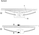
- Fig. 1-3 show the Rolltilger invention from different arrangements and positions.
- Fig. 1 (a) - (c) shows a Rollentilger which consists of the entire moving part, which rolls on a circular arc-shaped track and thus moves a circular motion, similar to a unilaterally deflected pendulum.
- the movable chassis (1) is moved on at least three rollers. For lateral support, cross-support rollers (1.7) are attached ( Fig. 3 ).
- the rails (4) are connected to the support structure (3).
- For adjustment holes can be attached.
- At least one of the rollers a driven by the roller rotating mass (flywheel 1.5) is attached.
- the moving part (1) moves in a circular motion in the direction of movement (1.8), the flywheel rotates in the direction (1.9).
- the rotational mass of the flywheel influences the natural frequency of the damper.
- the natural frequency of the absorber can be set exactly to the required values by means of different flywheel mass.
- the absorber comprises a parking brake (2) which ensures that it is released when the system is at a standstill.
- an electric magnet (2.1) is attached to at least one or more leaf springs so that it can move axially. As long as the magnet is de-energized, it is retained by the leaf springs (2.2). If he is energized, he moves to the flywheel and brakes it off. Since the flywheel at the outer diameter has a higher speed and thus smaller portion forces than the absorber itself, relatively small magnets are sufficient for braking.
- the magnet can also act on other movable part (1) as a holding structure.
- the size of the flywheel increases with increasing mass, and with increasing radius at which the mass acts.
- the effect on the absorber frequency increases with increasing flywheel mass and with increasing speed squared. Therefore, the largest possible flywheel is driven with the smallest possible role in the first approach, so that the flywheel and especially the speed are as large as possible.
- the adjustment of the natural frequency of the absorber takes place in which more or less mass is attached to the flywheel. At the same time it is also possible to influence the natural frequency by the flywheel (1.6) is displaced radially. It is important that the Friction of the wheel is sufficient to drive the mass with the appropriate acceleration. It is advantageous that in the tricycle assembly, the flywheel is attached to one of the three wheels, so that half of the mass acts on a wheel. At the same time, the load on this drive wheel (1.3) increases with increasing vibration mass, which at the same time helps to drive the larger vibration mass with a constant friction factor. With this method, the natural frequency of the absorber can be detuned by 10% to 30%.
- the moment of inertia of the flywheel (1.6) is defined by mass x distance to the square. [kg x mm 2 ]. Due to the weight of the oscillating mass and the possible friction between the drive wheel and rail dependent maximum driving force maximum momentum and thus the size of the flywheel 1.6 with flywheel 1.5 is limited. A drive wheel with a larger radius can also drive a correspondingly larger momentum, but has a smaller speed result. For example, in a 0.25 Hz absorber system with a radius of the drive wheel of 100 mm with the described system per kg main absorber mass (1.1) -with half load on the drive wheel (1.3) -a total rotation mass (1.6) of about 5000 kg x mm 2 are driven.
- the frequency between 10 and 30% in particular be influenced by about 20%.
- a diameter of the flywheel of 450mm for example, this results in a rotating mass of about 0.1 kg / kg Tilgermati.
- about 10% of the main Tilger mass (1.1) must rotate as a rotational mass (1.6) with a diameter of 450 mm.
- the load on the drive wheel (1.3) and thus the possible flywheel mass can be increased.
- a high coefficient of friction between the drive wheel and the rail also has a positive effect on the possible frequency spread. Since an adjustment range of + -5% is sufficient for adapting the usual frequency deviation of identical towers, the setting options achievable with the system do not have to be fully utilized.
- the mass of the flywheel (1.5) is a fixed size, which must be driven by the friction between the drive wheel (1.3) and rail / tube, but does not contribute significantly to the adjustment range. Therefore, the rotational mass (1.6) of the flywheel (1.5) should be as small as possible.
- the flywheel (1.5) is preferably made of a light metal or plastic and is used for the largest possible adjustment. A further enlargement of the adjustment range is possible through the use of racks, chains or gears, which drive the drive wheel directly or indirectly positively.
- Vibrations and shocks caused by extraordinary influences may place more stress on the absorber system than is usual in general operation. Thus, it is possible that the vibration damper is deflected more than usually occurs in normal operation.
- a repository damper according to the prior art can be used.
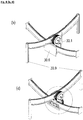
- a simple further embodiment according to the invention in connection with a stronger damping of strong oscillatory movements of the absorber is the in Fig. 5 and 6 described friction damper (20), which is effective only at large deflections of the absorber.
- This friction damper comprises, for example, a lever (20.1), which is mounted in the joint (20.4) and is prevented by the stop (20.5) at the bottom down.
- the lever may include an additional friction lining, with which it slides at a larger amplitude on at least one wheel and this brakes.
- an additional friction lining With increasing distance due to the geometric conditions and by the action of the mass (20.2) increases the contact pressure of the lever on the wheel and thus the friction.
- the mass (20.2) is displaceable on the longitudinal axis of the lever, the damping of this system can be adapted to the requirements.
- the stop (20.5) the lever is adjusted so that when approaching the lever still a gap (20.6) is present, so that the entry of the roller into the lever can be made continuously.
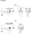
- Fig. 8 shows, for example, a system of combined vibration absorbers, in which two running devices / holding devices are arranged crosswise, preferably at a 90 ° angle.
- the structure is such that a curved running rail (30.3) has only one running gear (30.1) without additional main mass.
- the flywheel (30.7) is attached.
- the drive above (30.1) is connected to the connecting element 30.2 with the support structure below (30.4).
- the radii of the running rails / running parallel to the movement can be different. Through different radii of the rails different frequencies can be set in different directions.
- the transmission already described can be used and thus correspondingly lower flywheel masses are used.
- the axially acting absorber can be placed in the upper part of the nacelle.
- a Tilger centered, a Tilger eccentric, or even several Tilger can be used.
- the absorbers can (50.2) are positioned on the nacelle. The absorbers can also run outside on the gondola outdoors.
- a housing is placed when placed on the nacelle.
- Today's gondolas have a width of more than 4 m, so that the absorbers can also be installed in the gondola in the transverse direction.
- a Tilger according to the invention transversely to the nacelle and a Tilger along the gondola (50.4), or the Tilger can according to the gondola transversely (50.6) or even within the gondola transversely (50.7) are installed.
- the absorber according to the invention is also ideally suited to be installed in the tower of the wind turbine, or in corresponding tall, slender buildings in order to dampen the low-frequency oscillations of less than 5 Hz, in particular less than 1 Hz. Since the tower is independent of the direction, in each case a damper must be provided for both directions in the tower. That can happen in one plane. Since, however, usually in the tower of a wind turbine further technical installations are necessary, which sometimes require considerable space, individual linear absorber according to the invention direction and height offset inside the tower can be installed where there is enough space, as in Fig. 11 shown.
- the absorber according to the invention is as in Fig. 12 shown, additionally equipped with a vertical spring, whereby the frequency can be further influenced.
- a vertically acting spring (60.4) eg via a cable, on the absorber and on the building / tower floor, or on a wall, fixed or clamped, the Feser cable length should have at least twice the length of the vibration path.
- the longitudinally adjustable steel spring (60.4) can now be braced more or less strongly, which influences the frequency of the absorber. It is also possible to combine the frequency setting via the flywheel with the frequency setting by the tension spring.
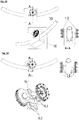
- FIGS. 13 and 14 represents vibration damper according to the invention, which instead of a track assembly as running a round barrel with suspension and in the specific case two rotational masses (1.5), wheels (70.1) (70.2) and support wheels (70.3).
- the vibration absorbers according to the invention can also be additionally damped, whereby correspondingly low attenuation values are required due to the relatively small absorber masses required.
- the running or driving wheels of the device according to the invention can spin or slip. This is especially the case of icing, moisture / moisture or pollution of the system by environmental influences or leaking lubricant the case.
- a further embodiment of the invention ( Fig. 17 ) are therefore the running surfaces of at least some of the wheels and rails involved either coated with a rigid plastic with low temperature-dependent expansion coefficient, or have a cam tooth profile or toothed belt profile (91) (92) with preferably flat contact surface (93).
- the tooth profile can itself be made of a suitably suitable plastic, with which the wheels / rollers and the rails are coated, or even be worked out as a surface structure.
- the friction-increasing profile can also be mounted only on a part of the wheels / rollers, but preferably it is present at least on the drive wheel (1.3).
- a conventional impeller (without tooth profile) may be connected to an axially disposed gear, which in turn on a arranged next to the track rail rack having the same radius as the track rail; rolls.
Landscapes
- Engineering & Computer Science (AREA)
- General Engineering & Computer Science (AREA)
- Mechanical Engineering (AREA)
- Architecture (AREA)
- Business, Economics & Management (AREA)
- Emergency Management (AREA)
- Environmental & Geological Engineering (AREA)
- Civil Engineering (AREA)
- Structural Engineering (AREA)
- Vibration Prevention Devices (AREA)
- Buildings Adapted To Withstand Abnormal External Influences (AREA)
Applications Claiming Priority (2)
| Application Number | Priority Date | Filing Date | Title |
|---|---|---|---|
| EP15002549 | 2015-08-28 | ||
| PCT/EP2016/001421 WO2017036581A1 (de) | 2015-08-28 | 2016-08-23 | Schwingungstilger mit rotierender masse |
Publications (2)
| Publication Number | Publication Date |
|---|---|
| EP3341627A1 EP3341627A1 (de) | 2018-07-04 |
| EP3341627B1 true EP3341627B1 (de) | 2019-09-25 |
Family
ID=54064122
Family Applications (1)
| Application Number | Title | Priority Date | Filing Date |
|---|---|---|---|
| EP16763442.7A Active EP3341627B1 (de) | 2015-08-28 | 2016-08-23 | Schwingungstilger mit rotierender masse |
Country Status (9)
| Country | Link |
|---|---|
| US (1) | US10711859B2 (da) |
| EP (1) | EP3341627B1 (da) |
| JP (1) | JP6965239B2 (da) |
| KR (1) | KR102581556B1 (da) |
| CN (1) | CN108350969B (da) |
| DK (1) | DK3341627T3 (da) |
| ES (1) | ES2763035T3 (da) |
| PT (1) | PT3341627T (da) |
| WO (1) | WO2017036581A1 (da) |
Cited By (4)
| Publication number | Priority date | Publication date | Assignee | Title |
|---|---|---|---|---|
| DE102019207826A1 (de) * | 2019-05-28 | 2020-12-03 | Zf Friedrichshafen Ag | Segmentierter Schwingungstilger |
| DE102022207585A1 (de) * | 2022-07-25 | 2024-01-25 | Maurer Engineering Gmbh | Bauwerksschwingungsdämpfer |
| EP4435253A1 (en) * | 2023-03-22 | 2024-09-25 | Totalenergies Onetech | An active vibration controlling device for a wind turbine |
| EP4435252A1 (en) * | 2023-03-22 | 2024-09-25 | Totalenergies Onetech | An active vibration controlling device for a wind turbine |
Families Citing this family (39)
| Publication number | Priority date | Publication date | Assignee | Title |
|---|---|---|---|---|
| DK3402999T3 (da) * | 2016-01-15 | 2023-11-06 | Fm Energie Gmbh & Co Kg | Svingningsdæmper med elektromagnetisk bremse til vindmøller |
| EP3388709B1 (de) * | 2017-04-13 | 2021-01-06 | Wölfel Engineering GmbH & Co. KG. | Schwingungsdämpferanordnung |
| EP3415786B1 (en) * | 2017-06-13 | 2021-10-20 | GE Renewable Technologies Wind B.V. | Tuned mass dampers for damping an oscillating movement of a structure |
| US11603821B2 (en) * | 2017-08-08 | 2023-03-14 | Fm Energie Gmbh & Co. Kg | Rotation damper and vibration absorber equipped therewith |
| ES3057923T3 (en) * | 2017-08-29 | 2026-03-05 | Ge Renewable Tech Wind Bv | Arrangements and methods for damping oscillations in structures |
| CA3085825A1 (en) * | 2017-12-14 | 2019-06-20 | Permasteelisa S.P.A. | Dynamic vibration damping system for high- rise buildings |
| CN108105303B (zh) * | 2017-12-19 | 2024-02-02 | 同济大学 | 拉索式旋转电涡流阻尼器 |
| US11255409B2 (en) | 2018-02-08 | 2022-02-22 | Esm Energie-Und Schwingungstechnik Mitsch Gmbh | Rotating vibration absorber comprising a belt drive |
| EP3781837A1 (de) * | 2018-04-18 | 2021-02-24 | FM Energie GmbH & Co. KG | Dämpfende kardanaufhängung für pendeltilger |
| CN112352116B (zh) * | 2018-08-22 | 2022-01-11 | 香港科技大学 | 小型低频波吸收器件 |
| DE102018007356A1 (de) * | 2018-09-18 | 2020-03-19 | Senvion Gmbh | Vorrichtung und Verfahren zum Dämpfen von Schwingungen eines Bauwerks |
| CN109252601B (zh) * | 2018-11-01 | 2020-04-21 | 徐州鼎力模具有限公司 | 应用于复杂路径的多向摩擦阻尼器及其应用 |
| DE102018218999A1 (de) * | 2018-11-07 | 2020-05-07 | Maurer Engineering Gmbh | Massedämpfer zur Dämpfung von Schwingungen eines Bauwerks, Bauwerk mit einem solchen Massedämpfer und Verfahren zur Einstellung der natürlichen Frequenz eines Massedämpfers |
| CN109610673B (zh) * | 2019-02-01 | 2023-11-24 | 青岛理工大学 | 主动转动惯量驱动控制系统 |
| US12006998B2 (en) | 2020-02-17 | 2024-06-11 | Fm Energie Gmbh & Co. Kg | Adaptive tuned mass damper for damping low excitation frequencies |
| CN113464384A (zh) * | 2020-03-31 | 2021-10-01 | 北京金风科创风电设备有限公司 | 阻尼装置及风力发电机组 |
| WO2021202987A1 (en) * | 2020-04-03 | 2021-10-07 | Duplicent, Llc | Earthquake stabilization device |
| CN112780003B (zh) * | 2021-01-26 | 2024-10-29 | 广州大学 | 离合型惯容质量阻尼器 |
| TWI737569B (zh) * | 2021-02-09 | 2021-08-21 | 國立臺灣科技大學 | 隔震裝置 |
| WO2022207146A1 (de) | 2021-03-31 | 2022-10-06 | Fm Energie Gmbh & Co.Kg | Temperaturadaptiver wirbelstrom-rotationsdämpfer |
| CN113356386B (zh) * | 2021-06-16 | 2022-09-20 | 华中科技大学 | 一种基于惯性放大机理的自适应电涡流阻尼器及其应用 |
| CN113864392B (zh) * | 2021-10-15 | 2023-07-28 | 国望智承(北京)振动控制技术有限公司 | 解耦式双曲线轨两自由度免震台 |
| US11852291B2 (en) * | 2022-02-23 | 2023-12-26 | Taiwan Semiconductor Manufacturing Company, Ltd. | Displacement control device for seismic events |
| US12410773B2 (en) | 2022-03-03 | 2025-09-09 | Ge Vernova Infrastructure Technology Llc | System and method for use of a tunable mechanical mass damper to reduce vibrations in wind turbine blades in a locked or idling condition of the rotor hub |
| US11572868B1 (en) * | 2022-03-03 | 2023-02-07 | General Electric Company | System and method for use of a tunable mass damper to reduce vibrations in wind turbine blades in a locked or idling condition of the rotor hub |
| CN114427191A (zh) * | 2022-03-07 | 2022-05-03 | 广州大学 | 一种拱桥式抗拉锥形变曲率变摩擦摆隔震支座 |
| EP4290096B1 (de) | 2022-06-09 | 2024-08-28 | Wölfel Engineering GmbH & Co. KG. | Schwingungstilgeranordnung |
| CN115434444B (zh) * | 2022-08-09 | 2023-09-15 | 厦门环寂高科有限公司 | 一种水平向调谐质量阻尼器 |
| CN115434855B (zh) * | 2022-09-30 | 2024-10-11 | 金风科技股份有限公司 | 风力发电机组及其振动控制方法 |
| CN116556527B (zh) * | 2023-05-10 | 2026-02-17 | 中建八局第三建设有限公司 | 一种半主动型隔震支座及隔震系统 |
| US12092082B1 (en) * | 2023-07-13 | 2024-09-17 | Ge Infrastructure Technology Llc | System and method for use of an automatically tunable spring mass damper to reduce vibrations in wind turbine blades |
| CN117306729A (zh) * | 2023-09-27 | 2023-12-29 | 同济大学 | 一种单向弧轨式类摆调谐质量阻尼器 |
| CN117515103B (zh) * | 2024-01-08 | 2024-04-02 | 石家庄铁道大学 | 电涡流阻尼器 |
| US12553489B2 (en) * | 2024-01-12 | 2026-02-17 | Taiwan Semiconductor Manufacturing Company Limited | Seismic event displacement mitigation |
| ES3039358A1 (es) * | 2024-04-19 | 2025-10-20 | Univ Del Pais Vasco / Euskal Herriko Unibertsitatea | Metodo y sistema de control de inclinacion de una estructura oscilante |
| EP4667772A1 (en) * | 2024-06-21 | 2025-12-24 | TotalEnergies OneTech | Vibration control device |
| CN118911303B (zh) * | 2024-07-22 | 2025-04-18 | 长安大学 | 一种基于动能回收原理的半主动控制摩擦摆隔震支座 |
| WO2026052602A1 (de) | 2024-09-04 | 2026-03-12 | Esm Energie- Und Schwingungstechnik Mitsch Gmbh | Schwingungstilgeranordnung für hohe schlanke bauwerke |
| CN119572680B (zh) * | 2024-11-26 | 2026-04-21 | 同济大学 | 一种摆式自适应惯容支座及惯容系数调整方法 |
Citations (3)
| Publication number | Priority date | Publication date | Assignee | Title |
|---|---|---|---|---|
| JPH04101838U (ja) * | 1991-02-08 | 1992-09-02 | 石川島播磨重工業株式会社 | 制振装置 |
| EP0834035A1 (en) * | 1995-06-15 | 1998-04-08 | CUNNINGHAM, John | Vibration isolation device and method |
| EP2746483A1 (de) * | 2012-12-21 | 2014-06-25 | Wölfel Beratende Ingenieure GmbH & Co. KG | Schwingungstilgeranordnurg |
Family Cites Families (21)
| Publication number | Priority date | Publication date | Assignee | Title |
|---|---|---|---|---|
| US4407395A (en) * | 1981-09-25 | 1983-10-04 | Suozzo Leonard S | Mechanical shock and sway arrestor |
| JP2841487B2 (ja) * | 1989-06-28 | 1998-12-24 | 石川島播磨重工業株式会社 | 構造物制振装置 |
| JPH04101838A (ja) * | 1990-08-22 | 1992-04-03 | Nippon Carbide Ind Co Inc | 新規な容器及びそれに使用する資材 |
| JPH0814207B2 (ja) * | 1990-10-24 | 1996-02-14 | 株式会社奥村組 | 建物の制振装置 |
| JPH086493B2 (ja) * | 1991-05-29 | 1996-01-24 | 鹿島建設株式会社 | 構造物の振動制御装置 |
| JPH0863041A (ja) * | 1994-08-16 | 1996-03-08 | Fuji Xerox Co Ltd | 画像形成装置の回転体駆動装置 |
| JPH08200438A (ja) | 1995-01-19 | 1996-08-06 | Ishikawajima Harima Heavy Ind Co Ltd | 揺れ止め装置 |
| US5713163A (en) * | 1995-01-19 | 1998-02-03 | Ishikawajima-Harima Heavy Industries Co. Ltd. | Vibration damping apparatus |
| JPH0953681A (ja) * | 1995-08-18 | 1997-02-25 | Univ Kyoto | 重力作用型動吸振器およびその振動周期調整法 |
| JP3324353B2 (ja) * | 1995-08-18 | 2002-09-17 | 京都大学長 | 振り子構造物 |
| US6230450B1 (en) * | 1996-12-27 | 2001-05-15 | Sumitomo Construction Co., Ltd. | Damping top, damping rod, and damping device using same |
| JP3833779B2 (ja) * | 1997-05-16 | 2006-10-18 | 株式会社奥村組 | 免震装置 |
| JPH1182506A (ja) * | 1997-09-04 | 1999-03-26 | Thk Kk | 三次元案内装置 |
| DE19856500B4 (de) | 1998-12-08 | 2005-12-08 | Franz Mitsch | Schwingungstilger |
| TW571038B (en) * | 1999-09-14 | 2004-01-11 | Thk Co Ltd | Base isolation device with damping mechanism |
| US7716881B2 (en) * | 2005-05-18 | 2010-05-18 | Chong-Shien Tsai | Shock suppressor |
| US8484911B2 (en) * | 2006-05-12 | 2013-07-16 | Earthquake Protection Systems, Inc. | Sliding pendulum seismic isolation system |
| JP2008249122A (ja) * | 2007-03-30 | 2008-10-16 | Kitakyushu Foundation For The Advancement Of Industry Science & Technology | 制振装置 |
| AU2008328829B2 (en) | 2007-11-28 | 2013-08-22 | Vestas Wind Systems A/S | Method for damping oscillations in a wind turbine |
| US8672107B2 (en) * | 2010-03-11 | 2014-03-18 | The United States Of America As Represented By The Administrator Of The National Aeronautics And Space Administration | Compact vibration damper |
| DK3402999T3 (da) * | 2016-01-15 | 2023-11-06 | Fm Energie Gmbh & Co Kg | Svingningsdæmper med elektromagnetisk bremse til vindmøller |
-
2016
- 2016-08-23 DK DK16763442.7T patent/DK3341627T3/da active
- 2016-08-23 ES ES16763442T patent/ES2763035T3/es active Active
- 2016-08-23 EP EP16763442.7A patent/EP3341627B1/de active Active
- 2016-08-23 WO PCT/EP2016/001421 patent/WO2017036581A1/de not_active Ceased
- 2016-08-23 US US15/755,575 patent/US10711859B2/en active Active
- 2016-08-23 PT PT167634427T patent/PT3341627T/pt unknown
- 2016-08-23 KR KR1020187008455A patent/KR102581556B1/ko active Active
- 2016-08-23 CN CN201680049589.1A patent/CN108350969B/zh active Active
- 2016-08-23 JP JP2018510955A patent/JP6965239B2/ja not_active Expired - Fee Related
Patent Citations (3)
| Publication number | Priority date | Publication date | Assignee | Title |
|---|---|---|---|---|
| JPH04101838U (ja) * | 1991-02-08 | 1992-09-02 | 石川島播磨重工業株式会社 | 制振装置 |
| EP0834035A1 (en) * | 1995-06-15 | 1998-04-08 | CUNNINGHAM, John | Vibration isolation device and method |
| EP2746483A1 (de) * | 2012-12-21 | 2014-06-25 | Wölfel Beratende Ingenieure GmbH & Co. KG | Schwingungstilgeranordnurg |
Cited By (8)
| Publication number | Priority date | Publication date | Assignee | Title |
|---|---|---|---|---|
| DE102019207826A1 (de) * | 2019-05-28 | 2020-12-03 | Zf Friedrichshafen Ag | Segmentierter Schwingungstilger |
| EP3976992A1 (de) * | 2019-05-28 | 2022-04-06 | ZF Friedrichshafen AG | Segmentierter schwingungstilger |
| US12209632B2 (en) | 2019-05-28 | 2025-01-28 | Zf Friedrichshafen Ag | Segmented vibration absorber |
| DE102022207585A1 (de) * | 2022-07-25 | 2024-01-25 | Maurer Engineering Gmbh | Bauwerksschwingungsdämpfer |
| EP4435253A1 (en) * | 2023-03-22 | 2024-09-25 | Totalenergies Onetech | An active vibration controlling device for a wind turbine |
| EP4435252A1 (en) * | 2023-03-22 | 2024-09-25 | Totalenergies Onetech | An active vibration controlling device for a wind turbine |
| WO2024194358A1 (en) * | 2023-03-22 | 2024-09-26 | Totalenergies Onetech | An active vibration controlling device for a wind turbine |
| WO2024194356A1 (en) * | 2023-03-22 | 2024-09-26 | Totalenergies Onetech | An active vibration controlling device for a wind turbine |
Also Published As
| Publication number | Publication date |
|---|---|
| US10711859B2 (en) | 2020-07-14 |
| CN108350969A (zh) | 2018-07-31 |
| DK3341627T3 (da) | 2020-01-06 |
| CN108350969B (zh) | 2021-04-20 |
| JP2018529901A (ja) | 2018-10-11 |
| KR20180044383A (ko) | 2018-05-02 |
| KR102581556B1 (ko) | 2023-09-21 |
| WO2017036581A8 (de) | 2018-08-23 |
| EP3341627A1 (de) | 2018-07-04 |
| PT3341627T (pt) | 2019-12-11 |
| US20180252287A1 (en) | 2018-09-06 |
| ES2763035T3 (es) | 2020-05-26 |
| JP6965239B2 (ja) | 2021-11-10 |
| WO2017036581A1 (de) | 2017-03-09 |
Similar Documents
| Publication | Publication Date | Title |
|---|---|---|
| EP3341627B1 (de) | Schwingungstilger mit rotierender masse | |
| EP3749878B1 (de) | Rotations-schwingungstilger mit riemenantrieb | |
| EP3665398B1 (de) | Schwingungstilger mit rotationsdämpfer | |
| WO2017121633A1 (de) | Schwingungstilger mit elektromagnetischer bremse für windkraftanlagen | |
| DE69617859T2 (de) | Dynamischer Schwingungsdämpfer | |
| EP2964506B1 (de) | Fahrwerk für schienenfahrzeuge | |
| EP0052249B1 (de) | Drehpositionierbare Anlage | |
| EP3781837A1 (de) | Dämpfende kardanaufhängung für pendeltilger | |
| DE102008005385B4 (de) | Schienengeführter Wagen, Einschienenbahnfahrzeug, Anlage und Verfahren zum Bewegen eines schienengebundenen Fahrzeugs auf einer flexiblen Schiene | |
| DE102005026141A1 (de) | Lagereinheit für ein langgestrecktes Rotorblatt einer Windkraftanlage sowie Verfahren zum Betrieb einer Windkraftanlage mit wenigstens einem derartig gelagerten Rotorblatt | |
| EP2935936B1 (de) | Fliehkraftpendeleinrichtung sowie antriebsstrang eines kraftfahrzeugs | |
| WO1985000577A1 (fr) | Unite d'entrainement de galets | |
| DE3922272A1 (de) | Aufzugsaggregat | |
| DE102007003470A1 (de) | Lagereinheit mit einstellbarem Reibmoment zur Bereitstellung einer Bremsfunktion | |
| DE2735649C2 (da) | ||
| DE19752635A1 (de) | Lagerbüchse für einen Kfz-Kraftübertragungsstrang | |
| EP3140566B1 (de) | Fliehkraftpendel mit axialer wälzlagerung | |
| DE102015204027A1 (de) | Fliehkraftpendeleinrichtung mit Druckfedern | |
| EP0081189A2 (de) | Vorrichtung zum Abbremsen von Gegenständen | |
| DE9203251U1 (de) | Fliehkraft-Antrieb | |
| WO2016177454A1 (de) | Ungedämpfter adaptiver schwingungstilger | |
| WO2026052602A1 (de) | Schwingungstilgeranordnung für hohe schlanke bauwerke | |
| DE3127954A1 (de) | Geschwindigkeitsregler fuer rollenbahnen | |
| EP3085986B1 (de) | Schwingungstilgervorrichtung | |
| DE102014204947A1 (de) | Drehschwingungsdämpfer |
Legal Events
| Date | Code | Title | Description |
|---|---|---|---|
| STAA | Information on the status of an ep patent application or granted ep patent |
Free format text: STATUS: THE INTERNATIONAL PUBLICATION HAS BEEN MADE |
|
| PUAI | Public reference made under article 153(3) epc to a published international application that has entered the european phase |
Free format text: ORIGINAL CODE: 0009012 |
|
| STAA | Information on the status of an ep patent application or granted ep patent |
Free format text: STATUS: REQUEST FOR EXAMINATION WAS MADE |
|
| 17P | Request for examination filed |
Effective date: 20180307 |
|
| AK | Designated contracting states |
Kind code of ref document: A1 Designated state(s): AL AT BE BG CH CY CZ DE DK EE ES FI FR GB GR HR HU IE IS IT LI LT LU LV MC MK MT NL NO PL PT RO RS SE SI SK SM TR |
|
| AX | Request for extension of the european patent |
Extension state: BA ME |
|
| DAV | Request for validation of the european patent (deleted) | ||
| DAX | Request for extension of the european patent (deleted) | ||
| REG | Reference to a national code |
Ref country code: DE Ref legal event code: R079 Ref document number: 502016006821 Country of ref document: DE Free format text: PREVIOUS MAIN CLASS: F16F0007100000 Ipc: E04B0001980000 |
|
| GRAP | Despatch of communication of intention to grant a patent |
Free format text: ORIGINAL CODE: EPIDOSNIGR1 |
|
| STAA | Information on the status of an ep patent application or granted ep patent |
Free format text: STATUS: GRANT OF PATENT IS INTENDED |
|
| RIC1 | Information provided on ipc code assigned before grant |
Ipc: F16F 7/10 20060101ALI20190315BHEP Ipc: E04B 1/98 20060101AFI20190315BHEP |
|
| INTG | Intention to grant announced |
Effective date: 20190404 |
|
| GRAS | Grant fee paid |
Free format text: ORIGINAL CODE: EPIDOSNIGR3 |
|
| GRAA | (expected) grant |
Free format text: ORIGINAL CODE: 0009210 |
|
| STAA | Information on the status of an ep patent application or granted ep patent |
Free format text: STATUS: THE PATENT HAS BEEN GRANTED |
|
| AK | Designated contracting states |
Kind code of ref document: B1 Designated state(s): AL AT BE BG CH CY CZ DE DK EE ES FI FR GB GR HR HU IE IS IT LI LT LU LV MC MK MT NL NO PL PT RO RS SE SI SK SM TR |
|
| REG | Reference to a national code |
Ref country code: GB Ref legal event code: FG4D Free format text: NOT ENGLISH |
|
| REG | Reference to a national code |
Ref country code: CH Ref legal event code: EP |
|
| REG | Reference to a national code |
Ref country code: DE Ref legal event code: R096 Ref document number: 502016006821 Country of ref document: DE |
|
| REG | Reference to a national code |
Ref country code: AT Ref legal event code: REF Ref document number: 1183960 Country of ref document: AT Kind code of ref document: T Effective date: 20191015 |
|
| REG | Reference to a national code |
Ref country code: IE Ref legal event code: FG4D Free format text: LANGUAGE OF EP DOCUMENT: GERMAN |
|
| REG | Reference to a national code |
Ref country code: PT Ref legal event code: SC4A Ref document number: 3341627 Country of ref document: PT Date of ref document: 20191211 Kind code of ref document: T Free format text: AVAILABILITY OF NATIONAL TRANSLATION Effective date: 20191128 |
|
| REG | Reference to a national code |
Ref country code: CH Ref legal event code: NV Representative=s name: BOVARD AG PATENT- UND MARKENANWAELTE, CH |
|
| REG | Reference to a national code |
Ref country code: DK Ref legal event code: T3 Effective date: 20191219 |
|
| REG | Reference to a national code |
Ref country code: NL Ref legal event code: MP Effective date: 20190925 |
|
| PG25 | Lapsed in a contracting state [announced via postgrant information from national office to epo] |
Ref country code: HR Free format text: LAPSE BECAUSE OF FAILURE TO SUBMIT A TRANSLATION OF THE DESCRIPTION OR TO PAY THE FEE WITHIN THE PRESCRIBED TIME-LIMIT Effective date: 20190925 Ref country code: BG Free format text: LAPSE BECAUSE OF FAILURE TO SUBMIT A TRANSLATION OF THE DESCRIPTION OR TO PAY THE FEE WITHIN THE PRESCRIBED TIME-LIMIT Effective date: 20191225 Ref country code: LT Free format text: LAPSE BECAUSE OF FAILURE TO SUBMIT A TRANSLATION OF THE DESCRIPTION OR TO PAY THE FEE WITHIN THE PRESCRIBED TIME-LIMIT Effective date: 20190925 Ref country code: SE Free format text: LAPSE BECAUSE OF FAILURE TO SUBMIT A TRANSLATION OF THE DESCRIPTION OR TO PAY THE FEE WITHIN THE PRESCRIBED TIME-LIMIT Effective date: 20190925 Ref country code: NO Free format text: LAPSE BECAUSE OF FAILURE TO SUBMIT A TRANSLATION OF THE DESCRIPTION OR TO PAY THE FEE WITHIN THE PRESCRIBED TIME-LIMIT Effective date: 20191225 Ref country code: FI Free format text: LAPSE BECAUSE OF FAILURE TO SUBMIT A TRANSLATION OF THE DESCRIPTION OR TO PAY THE FEE WITHIN THE PRESCRIBED TIME-LIMIT Effective date: 20190925 |
|
| REG | Reference to a national code |
Ref country code: LT Ref legal event code: MG4D |
|
| PG25 | Lapsed in a contracting state [announced via postgrant information from national office to epo] |
Ref country code: RS Free format text: LAPSE BECAUSE OF FAILURE TO SUBMIT A TRANSLATION OF THE DESCRIPTION OR TO PAY THE FEE WITHIN THE PRESCRIBED TIME-LIMIT Effective date: 20190925 Ref country code: GR Free format text: LAPSE BECAUSE OF FAILURE TO SUBMIT A TRANSLATION OF THE DESCRIPTION OR TO PAY THE FEE WITHIN THE PRESCRIBED TIME-LIMIT Effective date: 20191226 Ref country code: LV Free format text: LAPSE BECAUSE OF FAILURE TO SUBMIT A TRANSLATION OF THE DESCRIPTION OR TO PAY THE FEE WITHIN THE PRESCRIBED TIME-LIMIT Effective date: 20190925 |
|
| PG25 | Lapsed in a contracting state [announced via postgrant information from national office to epo] |
Ref country code: NL Free format text: LAPSE BECAUSE OF FAILURE TO SUBMIT A TRANSLATION OF THE DESCRIPTION OR TO PAY THE FEE WITHIN THE PRESCRIBED TIME-LIMIT Effective date: 20190925 Ref country code: EE Free format text: LAPSE BECAUSE OF FAILURE TO SUBMIT A TRANSLATION OF THE DESCRIPTION OR TO PAY THE FEE WITHIN THE PRESCRIBED TIME-LIMIT Effective date: 20190925 Ref country code: IT Free format text: LAPSE BECAUSE OF FAILURE TO SUBMIT A TRANSLATION OF THE DESCRIPTION OR TO PAY THE FEE WITHIN THE PRESCRIBED TIME-LIMIT Effective date: 20190925 Ref country code: RO Free format text: LAPSE BECAUSE OF FAILURE TO SUBMIT A TRANSLATION OF THE DESCRIPTION OR TO PAY THE FEE WITHIN THE PRESCRIBED TIME-LIMIT Effective date: 20190925 Ref country code: AL Free format text: LAPSE BECAUSE OF FAILURE TO SUBMIT A TRANSLATION OF THE DESCRIPTION OR TO PAY THE FEE WITHIN THE PRESCRIBED TIME-LIMIT Effective date: 20190925 Ref country code: PL Free format text: LAPSE BECAUSE OF FAILURE TO SUBMIT A TRANSLATION OF THE DESCRIPTION OR TO PAY THE FEE WITHIN THE PRESCRIBED TIME-LIMIT Effective date: 20190925 |
|
| REG | Reference to a national code |
Ref country code: ES Ref legal event code: FG2A Ref document number: 2763035 Country of ref document: ES Kind code of ref document: T3 Effective date: 20200526 |
|
| PG25 | Lapsed in a contracting state [announced via postgrant information from national office to epo] |
Ref country code: SM Free format text: LAPSE BECAUSE OF FAILURE TO SUBMIT A TRANSLATION OF THE DESCRIPTION OR TO PAY THE FEE WITHIN THE PRESCRIBED TIME-LIMIT Effective date: 20190925 Ref country code: SK Free format text: LAPSE BECAUSE OF FAILURE TO SUBMIT A TRANSLATION OF THE DESCRIPTION OR TO PAY THE FEE WITHIN THE PRESCRIBED TIME-LIMIT Effective date: 20190925 Ref country code: IS Free format text: LAPSE BECAUSE OF FAILURE TO SUBMIT A TRANSLATION OF THE DESCRIPTION OR TO PAY THE FEE WITHIN THE PRESCRIBED TIME-LIMIT Effective date: 20200224 Ref country code: CZ Free format text: LAPSE BECAUSE OF FAILURE TO SUBMIT A TRANSLATION OF THE DESCRIPTION OR TO PAY THE FEE WITHIN THE PRESCRIBED TIME-LIMIT Effective date: 20190925 |
|
| REG | Reference to a national code |
Ref country code: DE Ref legal event code: R097 Ref document number: 502016006821 Country of ref document: DE |
|
| PG2D | Information on lapse in contracting state deleted |
Ref country code: IS |
|
| PG25 | Lapsed in a contracting state [announced via postgrant information from national office to epo] |
Ref country code: IS Free format text: LAPSE BECAUSE OF FAILURE TO SUBMIT A TRANSLATION OF THE DESCRIPTION OR TO PAY THE FEE WITHIN THE PRESCRIBED TIME-LIMIT Effective date: 20200126 |
|
| PLBE | No opposition filed within time limit |
Free format text: ORIGINAL CODE: 0009261 |
|
| STAA | Information on the status of an ep patent application or granted ep patent |
Free format text: STATUS: NO OPPOSITION FILED WITHIN TIME LIMIT |
|
| 26N | No opposition filed |
Effective date: 20200626 |
|
| PG25 | Lapsed in a contracting state [announced via postgrant information from national office to epo] |
Ref country code: SI Free format text: LAPSE BECAUSE OF FAILURE TO SUBMIT A TRANSLATION OF THE DESCRIPTION OR TO PAY THE FEE WITHIN THE PRESCRIBED TIME-LIMIT Effective date: 20190925 |
|
| PG25 | Lapsed in a contracting state [announced via postgrant information from national office to epo] |
Ref country code: MC Free format text: LAPSE BECAUSE OF FAILURE TO SUBMIT A TRANSLATION OF THE DESCRIPTION OR TO PAY THE FEE WITHIN THE PRESCRIBED TIME-LIMIT Effective date: 20190925 |
|
| PG25 | Lapsed in a contracting state [announced via postgrant information from national office to epo] |
Ref country code: LU Free format text: LAPSE BECAUSE OF NON-PAYMENT OF DUE FEES Effective date: 20200823 |
|
| REG | Reference to a national code |
Ref country code: BE Ref legal event code: MM Effective date: 20200831 |
|
| PG25 | Lapsed in a contracting state [announced via postgrant information from national office to epo] |
Ref country code: PT Free format text: LAPSE BECAUSE OF NON-PAYMENT OF DUE FEES Effective date: 20210524 |
|
| PG25 | Lapsed in a contracting state [announced via postgrant information from national office to epo] |
Ref country code: IE Free format text: LAPSE BECAUSE OF NON-PAYMENT OF DUE FEES Effective date: 20200823 Ref country code: BE Free format text: LAPSE BECAUSE OF NON-PAYMENT OF DUE FEES Effective date: 20200831 |
|
| PGFP | Annual fee paid to national office [announced via postgrant information from national office to epo] |
Ref country code: TR Payment date: 20210719 Year of fee payment: 6 |
|
| PG25 | Lapsed in a contracting state [announced via postgrant information from national office to epo] |
Ref country code: MT Free format text: LAPSE BECAUSE OF FAILURE TO SUBMIT A TRANSLATION OF THE DESCRIPTION OR TO PAY THE FEE WITHIN THE PRESCRIBED TIME-LIMIT Effective date: 20190925 Ref country code: CY Free format text: LAPSE BECAUSE OF FAILURE TO SUBMIT A TRANSLATION OF THE DESCRIPTION OR TO PAY THE FEE WITHIN THE PRESCRIBED TIME-LIMIT Effective date: 20190925 |
|
| PG25 | Lapsed in a contracting state [announced via postgrant information from national office to epo] |
Ref country code: MK Free format text: LAPSE BECAUSE OF FAILURE TO SUBMIT A TRANSLATION OF THE DESCRIPTION OR TO PAY THE FEE WITHIN THE PRESCRIBED TIME-LIMIT Effective date: 20190925 |
|
| PGFP | Annual fee paid to national office [announced via postgrant information from national office to epo] |
Ref country code: ES Payment date: 20250901 Year of fee payment: 10 |
|
| PGFP | Annual fee paid to national office [announced via postgrant information from national office to epo] |
Ref country code: DK Payment date: 20250825 Year of fee payment: 10 |
|
| PGFP | Annual fee paid to national office [announced via postgrant information from national office to epo] |
Ref country code: GB Payment date: 20250703 Year of fee payment: 10 |
|
| PGFP | Annual fee paid to national office [announced via postgrant information from national office to epo] |
Ref country code: FR Payment date: 20250812 Year of fee payment: 10 Ref country code: AT Payment date: 20250828 Year of fee payment: 10 |
|
| PGFP | Annual fee paid to national office [announced via postgrant information from national office to epo] |
Ref country code: CH Payment date: 20250901 Year of fee payment: 10 |
|
| PGFP | Annual fee paid to national office [announced via postgrant information from national office to epo] |
Ref country code: DE Payment date: 20251029 Year of fee payment: 10 |