EP3432006A1 - Dispositif électronique avec un capteur de courant intégré dans un radiateur - Google Patents
Dispositif électronique avec un capteur de courant intégré dans un radiateur Download PDFInfo
- Publication number
- EP3432006A1 EP3432006A1 EP18171375.1A EP18171375A EP3432006A1 EP 3432006 A1 EP3432006 A1 EP 3432006A1 EP 18171375 A EP18171375 A EP 18171375A EP 3432006 A1 EP3432006 A1 EP 3432006A1
- Authority
- EP
- European Patent Office
- Prior art keywords
- current
- electronic device
- current sensor
- cooling element
- power line
- Prior art date
- Legal status (The legal status is an assumption and is not a legal conclusion. Google has not performed a legal analysis and makes no representation as to the accuracy of the status listed.)
- Granted
Links
Images

Classifications
-
- H—ELECTRICITY
- H10—SEMICONDUCTOR DEVICES; ELECTRIC SOLID-STATE DEVICES NOT OTHERWISE PROVIDED FOR
- H10W—GENERIC PACKAGES, INTERCONNECTIONS, CONNECTORS OR OTHER CONSTRUCTIONAL DETAILS OF DEVICES COVERED BY CLASS H10
- H10W40/00—Arrangements for thermal protection or thermal control
- H10W40/20—Arrangements for cooling
- H10W40/22—Arrangements for cooling characterised by their shape, e.g. having conical or cylindrical projections
-
- G—PHYSICS
- G01—MEASURING; TESTING
- G01R—MEASURING ELECTRIC VARIABLES; MEASURING MAGNETIC VARIABLES
- G01R15/00—Details of measuring arrangements of the types provided for in groups G01R17/00 - G01R29/00, G01R33/00 - G01R33/26 or G01R35/00
- G01R15/14—Adaptations providing voltage or current isolation, e.g. for high-voltage or high-current networks
- G01R15/20—Adaptations providing voltage or current isolation, e.g. for high-voltage or high-current networks using galvano-magnetic devices, e.g. Hall-effect devices, i.e. measuring a magnetic field via the interaction between a current and a magnetic field, e.g. magneto resistive or Hall effect devices
- G01R15/202—Adaptations providing voltage or current isolation, e.g. for high-voltage or high-current networks using galvano-magnetic devices, e.g. Hall-effect devices, i.e. measuring a magnetic field via the interaction between a current and a magnetic field, e.g. magneto resistive or Hall effect devices using Hall-effect devices
-
- B—PERFORMING OPERATIONS; TRANSPORTING
- B60—VEHICLES IN GENERAL
- B60R—VEHICLES, VEHICLE FITTINGS, OR VEHICLE PARTS, NOT OTHERWISE PROVIDED FOR
- B60R16/00—Electric or fluid circuits specially adapted for vehicles and not otherwise provided for; Arrangement of elements of electric or fluid circuits specially adapted for vehicles and not otherwise provided for
- B60R16/02—Electric or fluid circuits specially adapted for vehicles and not otherwise provided for; Arrangement of elements of electric or fluid circuits specially adapted for vehicles and not otherwise provided for electric constitutive elements
-
- G—PHYSICS
- G01—MEASURING; TESTING
- G01R—MEASURING ELECTRIC VARIABLES; MEASURING MAGNETIC VARIABLES
- G01R1/00—Details of instruments or arrangements of the types included in groups G01R5/00 - G01R13/00 and G01R31/00
- G01R1/02—General constructional details
- G01R1/18—Screening arrangements against electric or magnetic fields, e.g. against earth's field
-
- G—PHYSICS
- G01—MEASURING; TESTING
- G01R—MEASURING ELECTRIC VARIABLES; MEASURING MAGNETIC VARIABLES
- G01R15/00—Details of measuring arrangements of the types provided for in groups G01R17/00 - G01R29/00, G01R33/00 - G01R33/26 or G01R35/00
- G01R15/14—Adaptations providing voltage or current isolation, e.g. for high-voltage or high-current networks
- G01R15/20—Adaptations providing voltage or current isolation, e.g. for high-voltage or high-current networks using galvano-magnetic devices, e.g. Hall-effect devices, i.e. measuring a magnetic field via the interaction between a current and a magnetic field, e.g. magneto resistive or Hall effect devices
- G01R15/207—Constructional details independent of the type of device used
-
- H—ELECTRICITY
- H10—SEMICONDUCTOR DEVICES; ELECTRIC SOLID-STATE DEVICES NOT OTHERWISE PROVIDED FOR
- H10W—GENERIC PACKAGES, INTERCONNECTIONS, CONNECTORS OR OTHER CONSTRUCTIONAL DETAILS OF DEVICES COVERED BY CLASS H10
- H10W70/00—Package substrates; Interposers; Redistribution layers [RDL]
- H10W70/60—Insulating or insulated package substrates; Interposers; Redistribution layers
- H10W70/611—Insulating or insulated package substrates; Interposers; Redistribution layers for connecting multiple chips together
-
- H—ELECTRICITY
- H10—SEMICONDUCTOR DEVICES; ELECTRIC SOLID-STATE DEVICES NOT OTHERWISE PROVIDED FOR
- H10W—GENERIC PACKAGES, INTERCONNECTIONS, CONNECTORS OR OTHER CONSTRUCTIONAL DETAILS OF DEVICES COVERED BY CLASS H10
- H10W70/00—Package substrates; Interposers; Redistribution layers [RDL]
- H10W70/60—Insulating or insulated package substrates; Interposers; Redistribution layers
- H10W70/62—Insulating or insulated package substrates; Interposers; Redistribution layers characterised by their interconnections
- H10W70/65—Shapes or dispositions of interconnections
-
- H—ELECTRICITY
- H10—SEMICONDUCTOR DEVICES; ELECTRIC SOLID-STATE DEVICES NOT OTHERWISE PROVIDED FOR
- H10W—GENERIC PACKAGES, INTERCONNECTIONS, CONNECTORS OR OTHER CONSTRUCTIONAL DETAILS OF DEVICES COVERED BY CLASS H10
- H10W90/00—Package configurations
-
- B—PERFORMING OPERATIONS; TRANSPORTING
- B60—VEHICLES IN GENERAL
- B60R—VEHICLES, VEHICLE FITTINGS, OR VEHICLE PARTS, NOT OTHERWISE PROVIDED FOR
- B60R16/00—Electric or fluid circuits specially adapted for vehicles and not otherwise provided for; Arrangement of elements of electric or fluid circuits specially adapted for vehicles and not otherwise provided for
- B60R16/02—Electric or fluid circuits specially adapted for vehicles and not otherwise provided for; Arrangement of elements of electric or fluid circuits specially adapted for vehicles and not otherwise provided for electric constitutive elements
- B60R16/03—Electric or fluid circuits specially adapted for vehicles and not otherwise provided for; Arrangement of elements of electric or fluid circuits specially adapted for vehicles and not otherwise provided for electric constitutive elements for supply of electrical power to vehicle subsystems or for
-
- G—PHYSICS
- G01—MEASURING; TESTING
- G01R—MEASURING ELECTRIC VARIABLES; MEASURING MAGNETIC VARIABLES
- G01R31/00—Arrangements for testing electric properties; Arrangements for locating electric faults; Arrangements for electrical testing characterised by what is being tested not provided for elsewhere
- G01R31/005—Testing of electric installations on transport means
- G01R31/006—Testing of electric installations on transport means on road vehicles, e.g. automobiles or trucks
-
- H—ELECTRICITY
- H02—GENERATION; CONVERSION OR DISTRIBUTION OF ELECTRIC POWER
- H02M—APPARATUS FOR CONVERSION BETWEEN AC AND AC, BETWEEN AC AND DC, OR BETWEEN DC AND DC, AND FOR USE WITH MAINS OR SIMILAR POWER SUPPLY SYSTEMS; CONVERSION OF DC OR AC INPUT POWER INTO SURGE OUTPUT POWER; CONTROL OR REGULATION THEREOF
- H02M7/00—Conversion of AC power input into DC power output; Conversion of DC power input into AC power output
- H02M7/003—Constructional details, e.g. physical layout, assembly, wiring or busbar connections
-
- H—ELECTRICITY
- H10—SEMICONDUCTOR DEVICES; ELECTRIC SOLID-STATE DEVICES NOT OTHERWISE PROVIDED FOR
- H10W—GENERIC PACKAGES, INTERCONNECTIONS, CONNECTORS OR OTHER CONSTRUCTIONAL DETAILS OF DEVICES COVERED BY CLASS H10
- H10W40/00—Arrangements for thermal protection or thermal control
- H10W40/10—Arrangements for heating
-
- H—ELECTRICITY
- H10—SEMICONDUCTOR DEVICES; ELECTRIC SOLID-STATE DEVICES NOT OTHERWISE PROVIDED FOR
- H10W—GENERIC PACKAGES, INTERCONNECTIONS, CONNECTORS OR OTHER CONSTRUCTIONAL DETAILS OF DEVICES COVERED BY CLASS H10
- H10W76/00—Containers; Fillings or auxiliary members therefor; Seals
- H10W76/10—Containers or parts thereof
- H10W76/12—Containers or parts thereof characterised by their shape
- H10W76/15—Containers comprising an insulating or insulated base
- H10W76/153—Containers comprising an insulating or insulated base having interconnections in passages through the insulating or insulated base
Definitions
- the invention relates to an electronic device with at least one component to be cooled, a cooling element for cooling the component to be cooled, at least one power line and a respective current sensor for detecting a current strength of a current flowing through the respective power line.
- the invention relates to a motor vehicle.
- AC sensors can be used.
- Hall sensors can be used.
- open-loop Hall sensors can be used which have a flux concentrator, for example a ring of soft iron guided around the pipe. In open-loop sensor technology, the Hall voltage is detected directly.
- the problem here is that corresponding Hall sensors are relatively large construction.
- the components of the Hall sensor can heat up during operation, which can potentially lead to measurement errors or the measurement accuracy drops.
- the invention is therefore based on the object of specifying a space-saving possibility for measuring a current intensity in an electronic device, which can be implemented in particular with low technical complexity.
- the object is achieved by an electronic device of the type mentioned above, wherein the cooling element has a recess into which the current sensor engages or in which the current sensor is arranged.
- the cooling element may for example be a cooling plate, which may serve to cool electrical semiconductor switches or other heat-generating components of the electronic device.
- the cooling plate may for example be a metal plate, which increases the surface for radiating heat due to its high thermal conductivity.
- the cooling element or the cooling plate comprises an active cooling.
- the cooling element or the cooling plate can be penetrated by cooling passages through which a cooling fluid flows.
- the current sensor can be designed as a prefabricated module, which is fastened to the cooling plate, in particular via a housing of the current sensor.
- the current sensor can be screwed, riveted, locked or glued to the cooling element.
- the current sensor may in particular be an alternating current sensor.
- a Hall sensor with flux concentrator can be used.
- the current sensor can provide a voltage which depends on the measured current intensity. This can be detected by a control device, in particular using an analog-to-digital converter.
- the electronic device may be an electronic module which has at least one defined connection for connection to further components.
- the components of the electronic module can be arranged in particular within a housing.
- the recess of the cooling element may in particular be an opening.
- the power line can serve to supply power to the electronic device, or it can be used to provide energy from the electronic device to another component.
- the electronic device is a current transformer, the current of one or more output lines can be measured.
- the power line connects several components of the electronic device together.
- the power line is passed through a recess of the current sensor.
- the current measurement may in particular be contactless.
- the recess may be at least partially surrounded by a flux concentrator of the current sensor, for example by an open soft iron ring.
- the recess can in particular pass through a housing of the current sensor.
- the power line can end at least on one side with an open contact area, which serves to connect a connecting means.
- the power line may terminate in a plug or socket.
- the recess of the cooling element may be an opening through which the power line is passed.
- the current sensor may be arranged in the opening and the power line may be passed through the current sensor.
- cooling of the power line in particular in the area of the current sensor, can be achieved.
- This makes it possible to use a power line which, at least in the region of the current sensor, has a smaller line cross-section than would be required for an uncooled line.
- a flux concentrator with a smaller inner diameter can be used at the same time, whereby a total of a smaller-sized current sensor can be realized.
- Several current sensors can be arranged together in the recess of the cooling element.
- the current sensors can be arranged in particular in a common housing. As a result, the electronic device can be constructed simpler. If a plurality of current sensors are arranged together in an opening, wherein the current lines are each guided by the current sensors, in particular by contact areas of the power lines on one side of the cooling element, a connecting element, for example a plug or a socket, be formed for all power lines. As a result, a connection of multiple power lines can be easily implemented.
- a housing having one or more current sensors can be shaped such that it is guided or held by the recess of the cooling element. If the recess is an opening, then the housing may have a support section which projects beyond the opening, so that the housing rests on the cooling element after insertion into the opening with the support section. As a result, a particularly simple assembly of the current sensor or the current sensors is achieved.
- the support portion may include a recess or aperture to guide, for example, a screw or rivet with which the current sensor is attached to the cooling element.
- the current sensor may comprise a flux concentrating element encompassing the power line, which has an opening in the circumferential direction in which a Hall probe is arranged.
- the flux concentration element may, for example, have an open ring shape or a C shape.
- Hall probes with flux concentrator are known in principle in the prior art and will not be explained in detail. In the case of a Hall probe, at least in open-loop measurements, a fixed current is applied to the Hall probe and a voltage which drops substantially perpendicular thereto is measured. Since there is a clear relationship between the induced field and a guided current and a voltage drop across a Hall probe and a field passing through the Hall probe, a current in the power line can thus be measured without contact. The relationship between a voltage drop across the Hall probe and the current can be approximated as linear. However, it is also possible to measure this relationship beforehand and store it, for example, as a value table in a control device which detects the measurement data of the Hall probe.
- the flux concentration element may for example consist of soft iron or another paramagnetic or soft magnetic material.
- the flux concentration element and / or the Hall probe may be at least partially, preferably completely, within the recess of the cooling element.
- the electronic device may be a power converter or comprise a power converter.
- it can be an inverter, in particular for an electric motor, for example a drive motor of a motor vehicle.
- the component to be cooled or at least one of the components to be cooled may be a semiconductor switch.
- the semiconductor switch may be a transistor, for example an IGBT or a mosfet. Circuits for converting currents by means of semiconductor switches are known in the art and therefore will not be explained. Compared with, for example, relays, semiconductor switches allow significantly shorter switching intervals. Meanwhile, semiconductor switches can be realized, which have a very low resistance in a closed switch. Nevertheless, in particular in a direction of high currents, as required, for example, for drive motors, a certain power dissipation from the semiconductor switch, whereby corresponding circuits are typically cooled. A cooling element necessary for this purpose can be used simultaneously in the electronic device according to the invention for receiving and for cooling the current sensor.
- the cooling element may be made of metal at least in the region of the recess.
- a cooling element made of metal in particular a cooling plate, has a good thermal conductivity and can thus serve to increase a surface through which heat can be radiated.
- it can be advantageous to additionally provide active cooling wherein, for example, cooling fluid can be passed through cooling passages of the cooling element.
- the at least partially forming the cooling element made of metal improves the electromagnetic shielding of the current sensor against external influences. This can serve to further increase the measurement accuracy. Alternatively or additionally, a smaller current sensor can be realized due to the improved electromagnetic shielding.
- the invention relates to a motor vehicle comprising an electronic device according to the invention.
- the electronic device can be used in particular as an inverter for an engine of the motor vehicle, especially a drive motor of the motor vehicle.
- the motor vehicle comprises a control device, by means of which the power supplied to the motor is regulated, wherein at least one of the current sensors detects a current supplied to the motor, wherein a sensor signal of this sensor is usable as an input variable of a power control.
- the control can regulate the current to a desired value, for example by a pulse width control of the semiconductor switches used in the direction of change.
- Fig. 1 shows an electronic device 1, with a plurality of components to be cooled 2, which are arranged on a printed circuit board 3 and are cooled by a cooling device 4.
- the electronic device 1 is an inverter which converts a direct current provided by a battery 5 and supplies an alternating current to a motor 6.
- the engine 6 may be, for example, a drive motor of a motor vehicle.
- the provision of the alternating current via a power line 7.
- a plurality of power lines 7 may be used to provide a three-phase current to the motor 6 for energizing the motor 6.
- the components 2 to be cooled may in particular be semiconductor switches which are used to convert the current.
- corresponding switching signals or pulse widths and phase positions can be preset by a control device 8.
- the cooling element 4 may be a cooling plate, which may be formed for example as a metal plate.
- cooling channels could be provided in the cooling element 4, through which a cooling fluid can be guided in order to further improve the cooling of the component 2 to be cooled.
- the electronic device 1 has a current sensor 9, which is arranged in a recess 10, namely an opening, of the cooling element 4.
- the construction of the current sensor 9 will be described later in detail with reference to FIG Fig. 2 and 3 be explained.
- the current sensor 9 is formed by a flux concentrator, which surrounds the power line 7 and which has an opening in which a Hall probe is arranged. If a solid current is conducted with such a Hall probe via second contacts, a voltage can be tapped via two further contacts which is approximately proportional to the current flowing through the current line 7. Non-linearities of this sensor can be compensated by a previous calibration, for which purpose a look-up table can be stored in the controller 8, for example.
- the power cable 7 is guided through a recess 11, namely an opening, of the current sensor 9 to allow a contactless measurement of the current.
- the construction shown of the electronic device 1 allows by the arrangement of the current sensor 9 in the cooling device 4, an integration of a current measurement with a low space consumption.
- both the current sensor 9 and the power line 7 are also cooled in the region of the current sensor 9 by the cooling element 4, the measurement accuracy of the current sensor 9 can be improved and the line cross-section of the Power line 7 can be reduced, which also allows the use of a more compact current sensor 9.
- FIG. 2 and 3 show detailed views of another embodiment of an electronic device.
- the structure is essentially the same as in Fig. 1 shown device, wherein instead of a power line 7 three power lines 7 are used to provide three phases of an alternating current to an external device, such as the motor 6.
- an external device such as the motor 6.
- three current sensors 9 are arranged for the three power lines 7. These are fastened to the cooling element 4 via a common housing 12.
- the housing 12 can in Fig. 2 be inserted from above into the recess 10 and rests with support portions 13 on the edge of the recess 10. These have openings to secure the housing 10 and thus the current sensors 9 with fastening elements 14, for example with screws, to the cooling element 4.
- the individual current sensors 9 are formed by a flow concentration element 15 encompassing the power line 7 and a Hall probe 16, the flux concentration element 15 having an opening in the circumferential direction in which the Hall probe 16 is arranged.
- the wiring of the Hall probe 16 is not shown for clarity.
- the sections 17 of the power lines 7, in which they pass through the cooling element 4 and the current sensor 9, have a narrowed cross-section. This is made possible by the fact that the power line 7 is cooled in this area 17 each by the cooling element 4, whereby the current carrying capacity is improved. This makes it possible for the recess 11 of the current sensor 9 or of the flux concentration element 15 to have a smaller diameter than would otherwise be required, with which the current sensor 9 can be made more compact overall.
- the power lines 7 have unilaterally open contacts 19, through which a plug 18 is formed in the region of the cooling element.
- the motor 6 can be connected via a corresponding connecting element.
- the cooling element 4 is formed at least in the region of the recess 10 made of metal, then the cooling element 4 can also serve for the electromagnetic shielding of the current sensor 9, whereby its measurement accuracy can be improved.
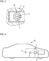
- Fig. 4 shows a motor vehicle 20 having a motor 6 as an electronic drive motor, which is powered by the battery 5, for example, a high-voltage battery.
- a motor 6 as an electronic drive motor, which is powered by the battery 5, for example, a high-voltage battery.
- an electronic device 1 is provided which, as to Fig. 1 is explained, is constructed as with respect to Fig. 2 and 3 has been explained, separate power lines 7 are used for the individual phases of the alternating current.
- the control device 8 data of a plurality of vehicle devices 21, for example, from an accelerator pedal sensor, detected to specify a target power for the engine 6.
- control device 8 In order to set this desired power, the control device 8 detects the currently provided current intensity via the current sensors 9 of the electronic device 1 and, on the other hand, gives pulse widths for the semiconductor switches of the electronic device in order to regulate the actually emitted current intensity to the desired current intensity.
Landscapes
- Physics & Mathematics (AREA)
- General Physics & Mathematics (AREA)
- Engineering & Computer Science (AREA)
- Mechanical Engineering (AREA)
- Measuring Instrument Details And Bridges, And Automatic Balancing Devices (AREA)
- Geometry (AREA)
- Inverter Devices (AREA)
Applications Claiming Priority (1)
| Application Number | Priority Date | Filing Date | Title |
|---|---|---|---|
| DE102017212434.2A DE102017212434A1 (de) | 2017-07-20 | 2017-07-20 | Elektronikeinrichtung mit wenigstens einer zu kühlenden Komponente |
Publications (2)
| Publication Number | Publication Date |
|---|---|
| EP3432006A1 true EP3432006A1 (fr) | 2019-01-23 |
| EP3432006B1 EP3432006B1 (fr) | 2024-12-11 |
Family
ID=62143061
Family Applications (1)
| Application Number | Title | Priority Date | Filing Date |
|---|---|---|---|
| EP18171375.1A Active EP3432006B1 (fr) | 2017-07-20 | 2018-05-09 | Dispositif électronique avec un capteur de courant intégré dans un radiateur |
Country Status (4)
| Country | Link |
|---|---|
| US (1) | US10784180B2 (fr) |
| EP (1) | EP3432006B1 (fr) |
| CN (1) | CN109283376B (fr) |
| DE (1) | DE102017212434A1 (fr) |
Cited By (1)
| Publication number | Priority date | Publication date | Assignee | Title |
|---|---|---|---|---|
| WO2023213346A1 (fr) * | 2022-05-06 | 2023-11-09 | Fachhochschule Kiel | Module semi-conducteur de puissance à connexion enfichable |
Citations (7)
| Publication number | Priority date | Publication date | Assignee | Title |
|---|---|---|---|---|
| WO1994027157A1 (fr) * | 1993-05-11 | 1994-11-24 | Abb Strömberg Kojeet Oy | Transducteur de mesure de courant base sur la mesure de densite de flux magnetique |
| US20060255793A1 (en) * | 2005-05-12 | 2006-11-16 | Michel Montreuil | Current sensor |
| US20080048642A1 (en) * | 2006-08-25 | 2008-02-28 | Denso Corporation | Current sensor |
| EP2261973A2 (fr) * | 2009-06-09 | 2010-12-15 | SEMIKRON Elektronik GmbH & Co. KG | Système électronique de puissance |
| DE102015202770A1 (de) * | 2015-02-16 | 2016-08-18 | Schaeffler Technologies AG & Co. KG | Vorrichtung zur integrierten Strommessung innerhalb einer Hochvolt-Kontaktierung eines Hybridmoduls und Hybridmodul mit der Vorrichtung |
| DE102015111204A1 (de) * | 2015-07-10 | 2017-01-12 | Semikron Elektronik Gmbh & Co. Kg | Leistungselektronisches Modul mit Lastanschlusselementen |
| EP3236724A1 (fr) * | 2016-04-18 | 2017-10-25 | SEMIKRON Elektronik GmbH & Co. KG | Système électronique de puissance et véhicule en étant équipé |
Family Cites Families (12)
| Publication number | Priority date | Publication date | Assignee | Title |
|---|---|---|---|---|
| US6426617B1 (en) * | 1999-09-28 | 2002-07-30 | Rockwell Automation Technologies, Inc. | Hall effect current sensor system packaging |
| FR2839417B1 (fr) * | 2002-05-03 | 2004-07-16 | Dav | Dispositif de commutation de puissance refroidi |
| DE102004054317B4 (de) | 2004-11-10 | 2014-05-15 | Mitsubishi Denki K.K. | Strommessvorrichtung |
| JP5975596B2 (ja) * | 2010-08-05 | 2016-08-23 | 矢崎総業株式会社 | 電流センサ構造 |
| CH703903B1 (de) | 2010-10-01 | 2014-04-30 | Melexis Tessenderlo Nv | Stromsensor. |
| JP5806134B2 (ja) | 2012-01-23 | 2015-11-10 | トヨタ自動車株式会社 | 電力変換装置 |
| DE102012206271A1 (de) * | 2012-04-17 | 2013-10-17 | Semikron Elektronik Gmbh & Co. Kg | Flüssigkeitsgekühlte Anordnung mit anreihbaren Leistungshalbleitermodulen und mindestens einer Kondensatoreinrichtung und Leistungshalbleitermodul hierzu |
| US20140091808A1 (en) * | 2012-09-28 | 2014-04-03 | Arc Suppression Technologies | Contact separation detector and methods therefor |
| US10180512B2 (en) * | 2015-04-06 | 2019-01-15 | Zonge International, Inc. | Circuits and methods for monitoring current in geophysical survey systems |
| US10128723B2 (en) * | 2015-07-07 | 2018-11-13 | Milwaukee Electric Tool Corporation | Printed circuit board spacer |
| JP2018004269A (ja) * | 2016-06-27 | 2018-01-11 | アイシン精機株式会社 | 電流センサ |
| JP6503413B2 (ja) * | 2017-05-31 | 2019-04-17 | 本田技研工業株式会社 | Dc/dcコンバータおよび電気機器 |
-
2017
- 2017-07-20 DE DE102017212434.2A patent/DE102017212434A1/de active Pending
-
2018
- 2018-05-09 EP EP18171375.1A patent/EP3432006B1/fr active Active
- 2018-05-30 US US15/992,469 patent/US10784180B2/en active Active
- 2018-07-19 CN CN201810798050.7A patent/CN109283376B/zh active Active
Patent Citations (7)
| Publication number | Priority date | Publication date | Assignee | Title |
|---|---|---|---|---|
| WO1994027157A1 (fr) * | 1993-05-11 | 1994-11-24 | Abb Strömberg Kojeet Oy | Transducteur de mesure de courant base sur la mesure de densite de flux magnetique |
| US20060255793A1 (en) * | 2005-05-12 | 2006-11-16 | Michel Montreuil | Current sensor |
| US20080048642A1 (en) * | 2006-08-25 | 2008-02-28 | Denso Corporation | Current sensor |
| EP2261973A2 (fr) * | 2009-06-09 | 2010-12-15 | SEMIKRON Elektronik GmbH & Co. KG | Système électronique de puissance |
| DE102015202770A1 (de) * | 2015-02-16 | 2016-08-18 | Schaeffler Technologies AG & Co. KG | Vorrichtung zur integrierten Strommessung innerhalb einer Hochvolt-Kontaktierung eines Hybridmoduls und Hybridmodul mit der Vorrichtung |
| DE102015111204A1 (de) * | 2015-07-10 | 2017-01-12 | Semikron Elektronik Gmbh & Co. Kg | Leistungselektronisches Modul mit Lastanschlusselementen |
| EP3236724A1 (fr) * | 2016-04-18 | 2017-10-25 | SEMIKRON Elektronik GmbH & Co. KG | Système électronique de puissance et véhicule en étant équipé |
Cited By (1)
| Publication number | Priority date | Publication date | Assignee | Title |
|---|---|---|---|---|
| WO2023213346A1 (fr) * | 2022-05-06 | 2023-11-09 | Fachhochschule Kiel | Module semi-conducteur de puissance à connexion enfichable |
Also Published As
| Publication number | Publication date |
|---|---|
| CN109283376B (zh) | 2021-08-17 |
| US10784180B2 (en) | 2020-09-22 |
| DE102017212434A1 (de) | 2019-01-24 |
| US20190027420A1 (en) | 2019-01-24 |
| CN109283376A (zh) | 2019-01-29 |
| EP3432006B1 (fr) | 2024-12-11 |
Similar Documents
| Publication | Publication Date | Title |
|---|---|---|
| DE102010044509A1 (de) | Umrichtervorrichtung | |
| DE102010000082B4 (de) | Schaltungsanordnung von elektronischen Leistungsschaltern einer Stromerzeugungsvorrichtung | |
| DE102018130954A1 (de) | Stromsensor | |
| EP2250509B1 (fr) | Dispositif de mesure du courant au moyen d'un capteur magnétosensible pour un système électronique de puissance | |
| DE102019003373B4 (de) | Leistungshalbleitervorrichtung mit integrierter Strommessung und Leistungsmodul diese aufweisend und Verfahren zum Messen eines Stroms darin | |
| WO2013091949A1 (fr) | Dispositif de commande pour commutateur à semi-conducteur d'un onduleur et procédé permettant de commander un onduleur | |
| DE102020208167A1 (de) | Leistungsmodul zum Betreiben eines Elektrofahrzeugantriebs mit einer verbesserten Temperaturbestimmung der Leistungshalbleiter | |
| DE102014208255B4 (de) | Schaltungsanordnung, Stromwandler mit einer Schaltungsanordnung | |
| EP3432006B1 (fr) | Dispositif électronique avec un capteur de courant intégré dans un radiateur | |
| DE102010036040A1 (de) | Strommesseinrichtung, insbesondere in einem Umrichter eines Flurförderzeugs | |
| DE102019114524A1 (de) | Anordnung mit einem Leistungselektroniksubstrat und einem Kontaktelement, Leistungselektronikeinheit und Stromrichter | |
| DE102022127337B3 (de) | Elektrische Vorrichtung mit einem oder mehreren Sensoren an fluidumströmten leistungsführenden und/oder leistungsschaltenden Elementen | |
| DE102004054317A1 (de) | Strommessvorrichtung | |
| AT523610B1 (de) | Umrichterbaugruppe | |
| DE102020106447A1 (de) | Anordnung zur Strommessung | |
| EP1921733B1 (fr) | Moteur triphasé et dispositif de commande | |
| DE102013213348B4 (de) | Leistungshalbleitermodul und elektrischer Antrieb mit einem Leistungshalbleitermodul | |
| EP3200225A2 (fr) | Module électronique comprenant un système semi-conducteur de puissance | |
| DE102016218703B4 (de) | Stromsteuervorrichtung und Herstellverfahren für Stromsteuervorrichtung | |
| WO2024165104A1 (fr) | Dispositif onduleur pour un essieu électrique d'un véhicule automobile et essieu électrique | |
| DE102009047235A1 (de) | Schaltungseinrichtung und Leistungsschaltkreis mit der Schaltungseinrichtung | |
| WO2006125407A1 (fr) | Dispositif pour mesurer l'intensite d'un courant | |
| DE102019207499A1 (de) | Wechselrichter für einen elektrifizierten Antriebsstrang | |
| EP4063058A1 (fr) | Module de source d'alimentation pour procédé d'assemblage | |
| DE102017208147B4 (de) | Elektronisches Bauteil und Leiterplatte mit diesem elektronischen Bauteil |
Legal Events
| Date | Code | Title | Description |
|---|---|---|---|
| PUAI | Public reference made under article 153(3) epc to a published international application that has entered the european phase |
Free format text: ORIGINAL CODE: 0009012 |
|
| STAA | Information on the status of an ep patent application or granted ep patent |
Free format text: STATUS: THE APPLICATION HAS BEEN PUBLISHED |
|
| AK | Designated contracting states |
Kind code of ref document: A1 Designated state(s): AL AT BE BG CH CY CZ DE DK EE ES FI FR GB GR HR HU IE IS IT LI LT LU LV MC MK MT NL NO PL PT RO RS SE SI SK SM TR |
|
| AX | Request for extension of the european patent |
Extension state: BA ME |
|
| STAA | Information on the status of an ep patent application or granted ep patent |
Free format text: STATUS: REQUEST FOR EXAMINATION WAS MADE |
|
| 17P | Request for examination filed |
Effective date: 20190723 |
|
| RBV | Designated contracting states (corrected) |
Designated state(s): AL AT BE BG CH CY CZ DE DK EE ES FI FR GB GR HR HU IE IS IT LI LT LU LV MC MK MT NL NO PL PT RO RS SE SI SK SM TR |
|
| STAA | Information on the status of an ep patent application or granted ep patent |
Free format text: STATUS: EXAMINATION IS IN PROGRESS |
|
| 17Q | First examination report despatched |
Effective date: 20220224 |
|
| P01 | Opt-out of the competence of the unified patent court (upc) registered |
Effective date: 20230529 |
|
| GRAP | Despatch of communication of intention to grant a patent |
Free format text: ORIGINAL CODE: EPIDOSNIGR1 |
|
| STAA | Information on the status of an ep patent application or granted ep patent |
Free format text: STATUS: GRANT OF PATENT IS INTENDED |
|
| RIC1 | Information provided on ipc code assigned before grant |
Ipc: H01L 23/36 20060101ALN20240912BHEP Ipc: H01L 23/055 20060101ALN20240912BHEP Ipc: H02M 7/00 20060101ALN20240912BHEP Ipc: G01R 15/20 20060101AFI20240912BHEP |
|
| INTG | Intention to grant announced |
Effective date: 20240924 |
|
| GRAS | Grant fee paid |
Free format text: ORIGINAL CODE: EPIDOSNIGR3 |
|
| GRAA | (expected) grant |
Free format text: ORIGINAL CODE: 0009210 |
|
| STAA | Information on the status of an ep patent application or granted ep patent |
Free format text: STATUS: THE PATENT HAS BEEN GRANTED |
|
| AK | Designated contracting states |
Kind code of ref document: B1 Designated state(s): AL AT BE BG CH CY CZ DE DK EE ES FI FR GB GR HR HU IE IS IT LI LT LU LV MC MK MT NL NO PL PT RO RS SE SI SK SM TR |
|
| REG | Reference to a national code |
Ref country code: GB Ref legal event code: FG4D Free format text: NOT ENGLISH |
|
| REG | Reference to a national code |
Ref country code: CH Ref legal event code: EP |
|
| REG | Reference to a national code |
Ref country code: DE Ref legal event code: R096 Ref document number: 502018015400 Country of ref document: DE |
|
| REG | Reference to a national code |
Ref country code: IE Ref legal event code: FG4D Free format text: LANGUAGE OF EP DOCUMENT: GERMAN |
|
| REG | Reference to a national code |
Ref country code: LT Ref legal event code: MG9D |
|
| PG25 | Lapsed in a contracting state [announced via postgrant information from national office to epo] |
Ref country code: HR Free format text: LAPSE BECAUSE OF FAILURE TO SUBMIT A TRANSLATION OF THE DESCRIPTION OR TO PAY THE FEE WITHIN THE PRESCRIBED TIME-LIMIT Effective date: 20241211 |
|
| PG25 | Lapsed in a contracting state [announced via postgrant information from national office to epo] |
Ref country code: FI Free format text: LAPSE BECAUSE OF FAILURE TO SUBMIT A TRANSLATION OF THE DESCRIPTION OR TO PAY THE FEE WITHIN THE PRESCRIBED TIME-LIMIT Effective date: 20241211 |
|
| PG25 | Lapsed in a contracting state [announced via postgrant information from national office to epo] |
Ref country code: BG Free format text: LAPSE BECAUSE OF FAILURE TO SUBMIT A TRANSLATION OF THE DESCRIPTION OR TO PAY THE FEE WITHIN THE PRESCRIBED TIME-LIMIT Effective date: 20241211 |
|
| REG | Reference to a national code |
Ref country code: NL Ref legal event code: MP Effective date: 20241211 |
|
| PG25 | Lapsed in a contracting state [announced via postgrant information from national office to epo] |
Ref country code: ES Free format text: LAPSE BECAUSE OF FAILURE TO SUBMIT A TRANSLATION OF THE DESCRIPTION OR TO PAY THE FEE WITHIN THE PRESCRIBED TIME-LIMIT Effective date: 20241211 |
|
| PG25 | Lapsed in a contracting state [announced via postgrant information from national office to epo] |
Ref country code: NO Free format text: LAPSE BECAUSE OF FAILURE TO SUBMIT A TRANSLATION OF THE DESCRIPTION OR TO PAY THE FEE WITHIN THE PRESCRIBED TIME-LIMIT Effective date: 20250311 |
|
| PG25 | Lapsed in a contracting state [announced via postgrant information from national office to epo] |
Ref country code: LV Free format text: LAPSE BECAUSE OF FAILURE TO SUBMIT A TRANSLATION OF THE DESCRIPTION OR TO PAY THE FEE WITHIN THE PRESCRIBED TIME-LIMIT Effective date: 20241211 Ref country code: GR Free format text: LAPSE BECAUSE OF FAILURE TO SUBMIT A TRANSLATION OF THE DESCRIPTION OR TO PAY THE FEE WITHIN THE PRESCRIBED TIME-LIMIT Effective date: 20250312 |
|
| PG25 | Lapsed in a contracting state [announced via postgrant information from national office to epo] |
Ref country code: RS Free format text: LAPSE BECAUSE OF FAILURE TO SUBMIT A TRANSLATION OF THE DESCRIPTION OR TO PAY THE FEE WITHIN THE PRESCRIBED TIME-LIMIT Effective date: 20250311 |
|
| PG25 | Lapsed in a contracting state [announced via postgrant information from national office to epo] |
Ref country code: NL Free format text: LAPSE BECAUSE OF FAILURE TO SUBMIT A TRANSLATION OF THE DESCRIPTION OR TO PAY THE FEE WITHIN THE PRESCRIBED TIME-LIMIT Effective date: 20241211 |
|
| PG25 | Lapsed in a contracting state [announced via postgrant information from national office to epo] |
Ref country code: SM Free format text: LAPSE BECAUSE OF FAILURE TO SUBMIT A TRANSLATION OF THE DESCRIPTION OR TO PAY THE FEE WITHIN THE PRESCRIBED TIME-LIMIT Effective date: 20241211 |
|
| PG25 | Lapsed in a contracting state [announced via postgrant information from national office to epo] |
Ref country code: PL Free format text: LAPSE BECAUSE OF FAILURE TO SUBMIT A TRANSLATION OF THE DESCRIPTION OR TO PAY THE FEE WITHIN THE PRESCRIBED TIME-LIMIT Effective date: 20241211 |
|
| PGFP | Annual fee paid to national office [announced via postgrant information from national office to epo] |
Ref country code: DE Payment date: 20250531 Year of fee payment: 8 |
|
| PG25 | Lapsed in a contracting state [announced via postgrant information from national office to epo] |
Ref country code: IS Free format text: LAPSE BECAUSE OF FAILURE TO SUBMIT A TRANSLATION OF THE DESCRIPTION OR TO PAY THE FEE WITHIN THE PRESCRIBED TIME-LIMIT Effective date: 20250411 |
|
| PG25 | Lapsed in a contracting state [announced via postgrant information from national office to epo] |
Ref country code: PT Free format text: LAPSE BECAUSE OF FAILURE TO SUBMIT A TRANSLATION OF THE DESCRIPTION OR TO PAY THE FEE WITHIN THE PRESCRIBED TIME-LIMIT Effective date: 20250411 |
|
| PG25 | Lapsed in a contracting state [announced via postgrant information from national office to epo] |
Ref country code: EE Free format text: LAPSE BECAUSE OF FAILURE TO SUBMIT A TRANSLATION OF THE DESCRIPTION OR TO PAY THE FEE WITHIN THE PRESCRIBED TIME-LIMIT Effective date: 20241211 |
|
| PG25 | Lapsed in a contracting state [announced via postgrant information from national office to epo] |
Ref country code: RO Free format text: LAPSE BECAUSE OF FAILURE TO SUBMIT A TRANSLATION OF THE DESCRIPTION OR TO PAY THE FEE WITHIN THE PRESCRIBED TIME-LIMIT Effective date: 20241211 |
|
| PG25 | Lapsed in a contracting state [announced via postgrant information from national office to epo] |
Ref country code: SK Free format text: LAPSE BECAUSE OF FAILURE TO SUBMIT A TRANSLATION OF THE DESCRIPTION OR TO PAY THE FEE WITHIN THE PRESCRIBED TIME-LIMIT Effective date: 20241211 |
|
| PG25 | Lapsed in a contracting state [announced via postgrant information from national office to epo] |
Ref country code: CZ Free format text: LAPSE BECAUSE OF FAILURE TO SUBMIT A TRANSLATION OF THE DESCRIPTION OR TO PAY THE FEE WITHIN THE PRESCRIBED TIME-LIMIT Effective date: 20241211 |
|
| PG25 | Lapsed in a contracting state [announced via postgrant information from national office to epo] |
Ref country code: IT Free format text: LAPSE BECAUSE OF FAILURE TO SUBMIT A TRANSLATION OF THE DESCRIPTION OR TO PAY THE FEE WITHIN THE PRESCRIBED TIME-LIMIT Effective date: 20241211 |
|
| PG25 | Lapsed in a contracting state [announced via postgrant information from national office to epo] |
Ref country code: SE Free format text: LAPSE BECAUSE OF FAILURE TO SUBMIT A TRANSLATION OF THE DESCRIPTION OR TO PAY THE FEE WITHIN THE PRESCRIBED TIME-LIMIT Effective date: 20241211 |
|
| REG | Reference to a national code |
Ref country code: DE Ref legal event code: R097 Ref document number: 502018015400 Country of ref document: DE |
|
| PG25 | Lapsed in a contracting state [announced via postgrant information from national office to epo] |
Ref country code: DK Free format text: LAPSE BECAUSE OF FAILURE TO SUBMIT A TRANSLATION OF THE DESCRIPTION OR TO PAY THE FEE WITHIN THE PRESCRIBED TIME-LIMIT Effective date: 20241211 |
|
| PLBE | No opposition filed within time limit |
Free format text: ORIGINAL CODE: 0009261 |
|
| STAA | Information on the status of an ep patent application or granted ep patent |
Free format text: STATUS: NO OPPOSITION FILED WITHIN TIME LIMIT |
|
| REG | Reference to a national code |
Ref country code: CH Ref legal event code: L10 Free format text: ST27 STATUS EVENT CODE: U-0-0-L10-L00 (AS PROVIDED BY THE NATIONAL OFFICE) Effective date: 20251022 |
|
| 26N | No opposition filed |
Effective date: 20250912 |
|
| REG | Reference to a national code |
Ref country code: CH Ref legal event code: H13 Free format text: ST27 STATUS EVENT CODE: U-0-0-H10-H13 (AS PROVIDED BY THE NATIONAL OFFICE) Effective date: 20251223 |
|
| PG25 | Lapsed in a contracting state [announced via postgrant information from national office to epo] |
Ref country code: LU Free format text: LAPSE BECAUSE OF NON-PAYMENT OF DUE FEES Effective date: 20250509 |
|
| PG25 | Lapsed in a contracting state [announced via postgrant information from national office to epo] |
Ref country code: CH Free format text: LAPSE BECAUSE OF NON-PAYMENT OF DUE FEES Effective date: 20250531 |
|
| GBPC | Gb: european patent ceased through non-payment of renewal fee |
Effective date: 20250509 |
|
| REG | Reference to a national code |
Ref country code: BE Ref legal event code: MM Effective date: 20250531 |
|
| PG25 | Lapsed in a contracting state [announced via postgrant information from national office to epo] |
Ref country code: MC Free format text: LAPSE BECAUSE OF FAILURE TO SUBMIT A TRANSLATION OF THE DESCRIPTION OR TO PAY THE FEE WITHIN THE PRESCRIBED TIME-LIMIT Effective date: 20241211 |