EP3858531A1 - Dispositif pour transmettre une force de torsion sur un fil - Google Patents
Dispositif pour transmettre une force de torsion sur un fil Download PDFInfo
- Publication number
- EP3858531A1 EP3858531A1 EP21152057.2A EP21152057A EP3858531A1 EP 3858531 A1 EP3858531 A1 EP 3858531A1 EP 21152057 A EP21152057 A EP 21152057A EP 3858531 A1 EP3858531 A1 EP 3858531A1
- Authority
- EP
- European Patent Office
- Prior art keywords
- wire
- support
- base
- rotation
- rolls
- Prior art date
- Legal status (The legal status is an assumption and is not a legal conclusion. Google has not performed a legal analysis and makes no representation as to the accuracy of the status listed.)
- Granted
Links
Images












Classifications
-
- B—PERFORMING OPERATIONS; TRANSPORTING
- B23—MACHINE TOOLS; METAL-WORKING NOT OTHERWISE PROVIDED FOR
- B23K—SOLDERING OR UNSOLDERING; WELDING; CLADDING OR PLATING BY SOLDERING OR WELDING; CUTTING BY APPLYING HEAT LOCALLY, e.g. FLAME CUTTING; WORKING BY LASER BEAM
- B23K9/00—Arc welding or cutting
- B23K9/12—Automatic feeding or moving of electrodes or work for spot or seam welding or cutting
- B23K9/133—Means for feeding electrodes, e.g. drums, rolls, motors
- B23K9/1333—Dereeling means
-
- B—PERFORMING OPERATIONS; TRANSPORTING
- B65—CONVEYING; PACKING; STORING; HANDLING THIN OR FILAMENTARY MATERIAL
- B65H—HANDLING THIN OR FILAMENTARY MATERIAL, e.g. SHEETS, WEBS, CABLES
- B65H49/00—Unwinding or paying-out filamentary material; Supporting, storing or transporting packages from which filamentary material is to be withdrawn or paid-out
- B65H49/02—Methods or apparatus in which packages do not rotate
- B65H49/04—Package-supporting devices
- B65H49/10—Package-supporting devices for one operative package and one or more reserve packages
-
- B—PERFORMING OPERATIONS; TRANSPORTING
- B23—MACHINE TOOLS; METAL-WORKING NOT OTHERWISE PROVIDED FOR
- B23K—SOLDERING OR UNSOLDERING; WELDING; CLADDING OR PLATING BY SOLDERING OR WELDING; CUTTING BY APPLYING HEAT LOCALLY, e.g. FLAME CUTTING; WORKING BY LASER BEAM
- B23K9/00—Arc welding or cutting
- B23K9/32—Accessories
-
- B—PERFORMING OPERATIONS; TRANSPORTING
- B23—MACHINE TOOLS; METAL-WORKING NOT OTHERWISE PROVIDED FOR
- B23K—SOLDERING OR UNSOLDERING; WELDING; CLADDING OR PLATING BY SOLDERING OR WELDING; CUTTING BY APPLYING HEAT LOCALLY, e.g. FLAME CUTTING; WORKING BY LASER BEAM
- B23K35/00—Rods, electrodes, materials, or media, for use in soldering, welding, or cutting
- B23K35/02—Rods, electrodes, materials, or media, for use in soldering, welding, or cutting characterised by mechanical features, e.g. shape
- B23K35/0255—Rods, electrodes, materials, or media, for use in soldering, welding, or cutting characterised by mechanical features, e.g. shape for use in welding
- B23K35/0261—Rods, electrodes or wires
-
- B—PERFORMING OPERATIONS; TRANSPORTING
- B23—MACHINE TOOLS; METAL-WORKING NOT OTHERWISE PROVIDED FOR
- B23K—SOLDERING OR UNSOLDERING; WELDING; CLADDING OR PLATING BY SOLDERING OR WELDING; CUTTING BY APPLYING HEAT LOCALLY, e.g. FLAME CUTTING; WORKING BY LASER BEAM
- B23K35/00—Rods, electrodes, materials, or media, for use in soldering, welding, or cutting
- B23K35/22—Rods, electrodes, materials, or media, for use in soldering, welding, or cutting characterised by the composition or nature of the material
- B23K35/24—Selection of soldering or welding materials proper
- B23K35/28—Selection of soldering or welding materials proper with the principal constituent melting at less than 950°C
- B23K35/286—Al as the principal constituent
-
- B—PERFORMING OPERATIONS; TRANSPORTING
- B23—MACHINE TOOLS; METAL-WORKING NOT OTHERWISE PROVIDED FOR
- B23K—SOLDERING OR UNSOLDERING; WELDING; CLADDING OR PLATING BY SOLDERING OR WELDING; CUTTING BY APPLYING HEAT LOCALLY, e.g. FLAME CUTTING; WORKING BY LASER BEAM
- B23K37/00—Auxiliary devices or processes, not specially adapted for a procedure covered by only one of the other main groups of this subclass
-
- B—PERFORMING OPERATIONS; TRANSPORTING
- B23—MACHINE TOOLS; METAL-WORKING NOT OTHERWISE PROVIDED FOR
- B23K—SOLDERING OR UNSOLDERING; WELDING; CLADDING OR PLATING BY SOLDERING OR WELDING; CUTTING BY APPLYING HEAT LOCALLY, e.g. FLAME CUTTING; WORKING BY LASER BEAM
- B23K9/00—Arc welding or cutting
- B23K9/12—Automatic feeding or moving of electrodes or work for spot or seam welding or cutting
- B23K9/124—Circuits or methods for feeding welding wire
-
- B—PERFORMING OPERATIONS; TRANSPORTING
- B23—MACHINE TOOLS; METAL-WORKING NOT OTHERWISE PROVIDED FOR
- B23K—SOLDERING OR UNSOLDERING; WELDING; CLADDING OR PLATING BY SOLDERING OR WELDING; CUTTING BY APPLYING HEAT LOCALLY, e.g. FLAME CUTTING; WORKING BY LASER BEAM
- B23K9/00—Arc welding or cutting
- B23K9/12—Automatic feeding or moving of electrodes or work for spot or seam welding or cutting
- B23K9/133—Means for feeding electrodes, e.g. drums, rolls, motors
- B23K9/1336—Driving means
-
- B—PERFORMING OPERATIONS; TRANSPORTING
- B65—CONVEYING; PACKING; STORING; HANDLING THIN OR FILAMENTARY MATERIAL
- B65H—HANDLING THIN OR FILAMENTARY MATERIAL, e.g. SHEETS, WEBS, CABLES
- B65H49/00—Unwinding or paying-out filamentary material; Supporting, storing or transporting packages from which filamentary material is to be withdrawn or paid-out
- B65H49/02—Methods or apparatus in which packages do not rotate
- B65H49/04—Package-supporting devices
- B65H49/06—Package-supporting devices for a single operative package
- B65H49/08—Package-supporting devices for a single operative package enclosing the package
-
- B—PERFORMING OPERATIONS; TRANSPORTING
- B65—CONVEYING; PACKING; STORING; HANDLING THIN OR FILAMENTARY MATERIAL
- B65H—HANDLING THIN OR FILAMENTARY MATERIAL, e.g. SHEETS, WEBS, CABLES
- B65H57/00—Guides for filamentary materials; Supports therefor
- B65H57/18—Guides for filamentary materials; Supports therefor mounted to facilitate unwinding of material from packages
-
- F—MECHANICAL ENGINEERING; LIGHTING; HEATING; WEAPONS; BLASTING
- F16—ENGINEERING ELEMENTS AND UNITS; GENERAL MEASURES FOR PRODUCING AND MAINTAINING EFFECTIVE FUNCTIONING OF MACHINES OR INSTALLATIONS; THERMAL INSULATION IN GENERAL
- F16D—COUPLINGS FOR TRANSMITTING ROTATION; CLUTCHES; BRAKES
- F16D7/00—Slip couplings, e.g. slipping on overload, for absorbing shock
- F16D7/02—Slip couplings, e.g. slipping on overload, for absorbing shock of the friction type
- F16D7/024—Slip couplings, e.g. slipping on overload, for absorbing shock of the friction type with axially applied torque limiting friction surfaces
- F16D7/025—Slip couplings, e.g. slipping on overload, for absorbing shock of the friction type with axially applied torque limiting friction surfaces with flat clutching surfaces, e.g. discs
-
- F—MECHANICAL ENGINEERING; LIGHTING; HEATING; WEAPONS; BLASTING
- F16—ENGINEERING ELEMENTS AND UNITS; GENERAL MEASURES FOR PRODUCING AND MAINTAINING EFFECTIVE FUNCTIONING OF MACHINES OR INSTALLATIONS; THERMAL INSULATION IN GENERAL
- F16H—GEARING
- F16H1/00—Toothed gearings for conveying rotary motion
- F16H1/02—Toothed gearings for conveying rotary motion without gears having orbital motion
- F16H1/20—Toothed gearings for conveying rotary motion without gears having orbital motion involving more than two intermeshing members
- F16H1/203—Toothed gearings for conveying rotary motion without gears having orbital motion involving more than two intermeshing members with non-parallel axes
-
- B—PERFORMING OPERATIONS; TRANSPORTING
- B23—MACHINE TOOLS; METAL-WORKING NOT OTHERWISE PROVIDED FOR
- B23K—SOLDERING OR UNSOLDERING; WELDING; CLADDING OR PLATING BY SOLDERING OR WELDING; CUTTING BY APPLYING HEAT LOCALLY, e.g. FLAME CUTTING; WORKING BY LASER BEAM
- B23K2103/00—Materials to be soldered, welded or cut
- B23K2103/08—Non-ferrous metals or alloys
- B23K2103/10—Aluminium or alloys thereof
-
- B—PERFORMING OPERATIONS; TRANSPORTING
- B65—CONVEYING; PACKING; STORING; HANDLING THIN OR FILAMENTARY MATERIAL
- B65H—HANDLING THIN OR FILAMENTARY MATERIAL, e.g. SHEETS, WEBS, CABLES
- B65H2515/00—Physical entities not provided for in groups B65H2511/00 or B65H2513/00
- B65H2515/30—Forces; Stresses
- B65H2515/32—Torque e.g. braking torque
-
- B—PERFORMING OPERATIONS; TRANSPORTING
- B65—CONVEYING; PACKING; STORING; HANDLING THIN OR FILAMENTARY MATERIAL
- B65H—HANDLING THIN OR FILAMENTARY MATERIAL, e.g. SHEETS, WEBS, CABLES
- B65H2701/00—Handled material; Storage means
- B65H2701/30—Handled filamentary material
- B65H2701/36—Wires
-
- B—PERFORMING OPERATIONS; TRANSPORTING
- B65—CONVEYING; PACKING; STORING; HANDLING THIN OR FILAMENTARY MATERIAL
- B65H—HANDLING THIN OR FILAMENTARY MATERIAL, e.g. SHEETS, WEBS, CABLES
- B65H2701/00—Handled material; Storage means
- B65H2701/30—Handled filamentary material
- B65H2701/36—Wires
- B65H2701/361—Semiconductor bonding wires
-
- F—MECHANICAL ENGINEERING; LIGHTING; HEATING; WEAPONS; BLASTING
- F16—ENGINEERING ELEMENTS AND UNITS; GENERAL MEASURES FOR PRODUCING AND MAINTAINING EFFECTIVE FUNCTIONING OF MACHINES OR INSTALLATIONS; THERMAL INSULATION IN GENERAL
- F16D—COUPLINGS FOR TRANSMITTING ROTATION; CLUTCHES; BRAKES
- F16D2121/00—Type of actuator operation force
- F16D2121/14—Mechanical
Definitions
- the invention relates to a device for imparting a torsional force onto a wire which can be a welding wire.
- Wires consumables are used in many industrial applications: from surface treatments like metallization to joining of metal parts in welding. In the coming years, wires will be increasingly utilized in the very important and continuously improving field of 3D printers.
- wire farms The concentration of packs containing large quantities of wire consumable in specific centralized areas (called "wire farms"), at a safe distance from dangerous sparks generated by the welding arc and where handling by forklifts is facilitated, is now made possible by the wire feed systems available in the marketplace which can help transport the wires smoothly and without friction through conduits with rolls over distances that can reach the 100 meters from the packs location to the welding or metallizing torch where the wire consumable is actually melted or fused.
- Being able to position large packs in a safe centralized area besides reducing the risks connected to their handling and transport and the welding sparks fire hazard, also allows an easier inspection without having to enter the production cell perimeter and eventually negatively interfere with the production cycles.
- Supports carrying wires are available in different formats: from small spools carrying as little as 0.5 kgs to bulk containers carrying up to 2 tons of product.
- a third and definitely more effective system was developed several years ago: a winding machine which plastically deforms the wire by straightening, stretching and turning it to impart a counter-torsion and subsequently lay it into a container in the shape of a horizontal coil.
- the wire When the wire is paid out for consumption, it can easily and smoothly be extracted without any major feeding difficulty from its stationary container without need of turntables or de-reeling devices and, if the winding process has been done correctly, it should not tangle prior to exiting the pack.
- the prior art teaches of many inventions focused on developing or improving all sorts of systems to retain and brake the wire during pay out: from plates of various shapes to spherical marbles dropped freely on the wire or retaining devices with a rotating wire guiding arm and ribbing underneath the plate to ensure that only one strand is being pulled out and not more loops at the same time; the problem is that if the wire being paid out from the pack is charged with too much tension, it inevitably drags some wire loops toward the central plate opening, where they can fall and tangle if they have moved during the transport, regardless of the type of retainer used.
- the first reaction is always to increase the retaining weight, in order to keep the wire in check, but if retainer plates are too heavy they will inevitably deform the wires, and deformed wires can cause arc wandering issues and consequent weld quality problems and even very heavy retainers cannot always keep the wire controlled.
- the equipment efficiency combined with the operator's skills and with a reliable wire retainer plate can truly make a difference in minimizing the residual tension left on the wire by the twist-free winding and ensuring a smooth wire feeding, but at the time of extracting the wire some other variables can intervene and negatively affect the wire performance: a bad adjustment of the wire feeder pressure rolls or worn out pressure rolls guiding grooves or "U” shaped as opposed to "V" shaped guiding grooves and vice-versa or, even worse, incorrect size grooves not matching the diameter of the wire in use.
- All of the above can contribute to charge a twist-free wound wire with tension, while it is being pulled from its container and as soon as the tension accumulation exceeds the braking effect exerted by the retainer plate, the wire springs out unchecked and eventually tangles and jams inside the pack, either in one single knot or in the form of an uncontrolled messy bundle of loops, thus causing the production interruption that the large bulk pack was designed to avoid in the first place.
- Scope of the invention is to intervene on the wire at some point between the coil and the wire feeder, by offsetting and neutralizing its residual tension to the point that even the payout controlling retainer plate might not be necessary or at least a very light and flexible retainer plate can be used instead.
- the invention is designed to ensure a smooth and trouble-free wire payout from bulk packs, especially with aluminum welding wires but it is applicable to all wires in general after they have been deposited into the bulk packs with the twist-free winding process.
- the device consists of a counter-tension rotating device which can be positioned anywhere between the wire coil and the wire feeder.
- the device is mounted on top of the dome, right at the point where the wire exits the pack.
- the device is equipped with at least one but preferably two (or more) wheels whose guiding grooves lock onto the wire and impart on it a counter-torsional movement by making it rotate on its axis in a given direction (clockwise or anti-clockwise), which is preferably the unwinding direction of the wire itself.
- This counter twist neutralizes whatever tension is still present on the wire regardless whether it is a consequence of an incorrect twist-free winding process or because of the excessive tension accumulated on the wire by a bad wheel pressure adjustment or by defective/worn out feeder roll grooves.
- the counter torsional force exerted on the wire conveniently maintains the wire pushed toward the external edge of the wire coil, thus preventing wire loops from falling uncontrolled into the open free space at the center of the bulk pack, even after they have been inadvertently displaced during handling or transport.
- the rotation of the tension-relief device can be activated in two ways:
- the tension relieving rotating speed cannot be subsequently adjusted or paused
- the tension-relief device operated by a motor which can be of any known type, like DC, AC, Brushless or Stepper
- a motor which can be of any known type, like DC, AC, Brushless or Stepper
- the control can determine when an excessive counter-tension force has accumulated on the wire and consequently activate or pause the rotation of the washer and grooved wheels through an electromagnet which engages or disengages the motor, as necessary.
- the motor engagement can be activated also with a pneumatic or magnetic piston which pushes the mobile part of the device which carries the motor against the rotating washer carrying the group of grooved wheels which contribute to impart the counter-torsion effect onto the feeding wire. While in this case the motor rotates continuously and it only engages the rotation washer when it needs to impart the counter twist to offset the accumulating tension on the wire, the motor can also engage continuously the rotation washer through a belt or bevel gears, and in this case its function has to be controlled and programmed through the external PLC.
- the neutralization of the tension generated by the counter-twisting of wire along its axis can actively contribute to a smooth wire payout even without the use of a retainer plate; or, if the preference goes to the employment of a retainer plate, it can at least be a very light and flexible one, and this can definitely be beneficial to prevent a possible deformation of softer aluminum wires.
- the retainer plate can still be placed on the wire coil and tied to the wire during handling and transportation, but it can be easily split in two or more sections for the purpose of being easily removed even with the wire already inserted into the guiding conduit.
- the invention provides a device for imparting a torsional force onto a wire, having a base, a support mounted so as to be rotatable with respect to the base around an axis of rotation, the axis of rotation coinciding with a wire path extending through the base and the support, a wire clutching device mounted on the support and adapted to engage at a wire guided along the wire path, and a rotation mechanism which is adapted for rotating the support with respect to the base.
- the wire clutching device mechanically engages the wire such that it can exert a torsional force onto the wire to the desired extent.
- the wire clutching device can be implemented in any form which allows wire pay out (meaning: a translational movement of the wire along the wire path) and at the same time imparting a rotational movement onto the wire.
- the wire clutching device is a pair of rolls which are mounted on the support, the rolls being arranged on opposite sides of the wire path, at least one of the rolls having a wire reception groove.
- a pair of rolls is a very simple and yet effective means for mechanically engaging at the wire so as to rotate it around its axis while at the same time allowing wire pay out.
- a biasing device is provided for biasing the two rolls against each other, allowing to adapt the clutching force to the particular requirements.
- the biasing device can comprise a hand wheel for applying a tightening torque to a biasing mechanism, a torque limiter being arranged in the torque path from the hand wheel to the biasing mechanism.
- the torque limiter prevents that excessive force is applied by the biasing device onto the wire.
- a spring-loaded cam mechanism which connects the hand wheel to a spindle nut.
- the cam mechanism allows implementing the torque limiting function in a technically simple yet effective manner.
- the torque limiter is adjustable so as to allow adapting the mechanism to different wires. Furthermore, the effect of wear can be compensated from time to time.
- the rotation mechanism can comprise a gear adapted for converting a movement of the wire along the wire path into a rotation of the support with respect to the base, thereby avoiding the need for a separate drive for rotating the wire clutching mechanism.
- the gear can be a bevel gear with a ring gear connected to the base and a pinion mounted rotatably on the support, resulting in a compact rotation mechanism.
- a worm drive can be used which is very compact.
- two mounting positions for the pinion are provided on the support.
- the torque limiter can be arranged between the gear and a shaft on which the gear is arranged. In this manner, a compact design can be achieved.
- the torque limiter is adjustable so as to adjust the mechanism to different properties of the wire.
- the torque limiter comprises a Belleville spring which is advantageous in as it provides a spring force which changes only in significantly over a wide range of compression of the spring.
- the rotation mechanism can comprise a drive motor mounted on the base and adapted for rotating the support with respect to the base.
- the drive motor can be operated independently from the speed with which the wire is drawn through the wire clutching device, thus allowing to control the torsional force applied to the wire independently from the wire withdrawal speed.
- a coupling device can be provided for connecting the motor to the support, allowing to disengage and engage the motor when appropriate.
- the coupling comprises an application device for urging a drive wheel connected to the drive motor, against a driven surface associated with the support.
- the device for applying a torsional force onto the wire can comprise a motor current sensor for detecting when excessive torsional forces are imparted onto the wire.
- the motor current is namely a good indication of the applied torsional force.
- the rotation mechanism can be an arm which has a wire receiving opening arranged eccentrically with respect to the axis of rotation of the support, thereby using the tension force of the wire to rotate the base.
- the invention also provides a system with a container in which an amount of wire is contained in the form of a coil consisting of a plurality of loops of wire, a device for imparting a torsional force onto a wire, the device being mounted above the wire, the device having a base, a support mounted so as to be rotatable with respect to the base around an axis of rotation, the axis of rotation coinciding with a wire path extending through the base and the support, a pair of rolls which are mounted on the support, the rolls being arranged on opposite sides of the wire path, at least one of the rolls having a wire reception groove, and a rotation mechanism which is adapted for rotating the support with respect to the base, the system further comprising at least one wire feeder which is arranged downstream of the device for imparting a torsional force onto the wire.
- the device for imparting a torsional force onto the wire is conveniently controlled directly from the control of the wire feeder.
- two wire feeders are being used, namely an auxiliary wire feeder which is arranged downstream of the device for imparting a rotation onto the wire, and a main wire feeder which is provided downstream of the auxiliary wire feeder and in a significant distance therefrom.
- Using two wire feeders allows arranging the wire container in a significant distance from the place where the wire is being consumed.
- the wire is a welding wire made from an aluminum alloy comprising magnesium. Field test have shown that his type of welding wire has a tendency internal stress when being stored for some time. Accordingly, the effect of the device for imparting a torsional force onto the welding wire is very beneficial.
- a container 1 in which a large quantity of wire 2 is contained in the form of a coil 3.
- Coil 3 consists of a plurality of loops formed from the wire 2.
- Wire 2 can be a welding wire. It can also be any consumable wire which is used for 3D printing, for metallization, etc.
- Wire 2 is withdrawn from container 1 through an upper opening of the container.
- a cover or a dome 4 can be placed on top of the container 1, with the main purpose of dome 4 being to prevent contamination of the interior of container 1 during the time period when the wire is being consumed.
- a retainer 5 is placed on the upper surface of coil 3.
- the main purpose of retainer 5 is to exert a braking force onto the wire and to create friction with its weight.
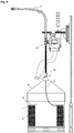
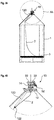
- Figure 4 shows a system according to the invention, which prevents loops from falling into the interior of coil 3 and from becoming entangled.
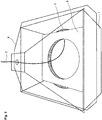
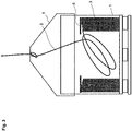
- An important element of the invention is a device 10 for imparting a torsional force onto the wire 2.
- device 10 rotates the wire around its own axis, thereby offsetting some of the residual stress in the wire and also ensuring that the loops of wire remain in their position within container 1.
- a wire feeder 6 Downstream of device 10, a wire feeder 6 can be arranged which advances the wire into a wire guide 7 and towards the place where the wire is being consumed, for example to a welding robot.
- a main wire feeder can be used close to the welding robot so that wire feeder 6 is an auxiliary wire feeder.
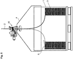
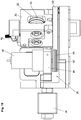
- Device 10 is arranged close to container 1. In the embodiment shown, device 10 is placed on dome 4 (please see in particular Figure 5 ).
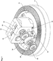
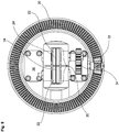
- Device 10 comprises a base 12 and a support 14.
- Support 14 is mounted so as to be rotatable with respect to base 12 around an axis 16 which coincides with a wire path along which wire 2 is guided through device 10.
- a wire inlet guide 15 is attached to support 14.
- a roller bearing 18 is used for mounting support 14 on base 12.
- a wire clutching device 20 is mounted on support 14. It here consists of two rolls 22 arranged on opposite sides of wire path 16, with both rolls 22 each having a wire reception groove 24.
- Wire reception grooves 24 have a width and depth adapted to the dimension of the particular wire so as to tightly engage the wire.
- Rotation mechanism 26 which is adapted for rotating the support with respect to the base.
- Rotation mechanism 26 is here formed from a gear, in particular a bevel gear 28, which comprises a ring gear 30 fixedly provided on base 12, and a pinion 32 which is mounted on support 14.
- Pinion 32 is connected via a gear drive 34 to one of rolls 22.
- rotation of the rolls is transmitted via the gears to pinion 32, which engages into ring gear 30. Accordingly, support 14 is rotated with respect to base 12 when the wire is drawn through device 10.
- the amount of torsional force to be applied onto the wire largely depends from characteristics of the wire. For some wires, it has been found out that applying 1.5 revolutions of wire clutching device 20 per loop of withdrawn wire provides good results.
- the ratio of revolutions per length of withdrawn wire can be adapted by selecting the size of rolls 22 and the transmission ratio of rotation mechanism 26.
- wire clutching device 20 should rotate in the same direction in which the withdrawn wire rotates within container 1. As an example, when looking into container 1 from the top and the wire is withdrawn in a clockwise direction, wire clutching device 20 should also rotate in a clockwise direction.
- a mounting position 36 is provided for mounting pinion 32 on the opposite side, thereby changing the direction of rotation.
- a torque limiter can be provided somewhere in the rotation mechanism 20.
- the torque limiter could be formed by spring-loaded friction disks or a similar mechanism.
- FIG. 9 A second embodiment of device 10 is shown in Figures 9 to 12 .
- the same reference numerals are being used, and reference is made to the above comments.
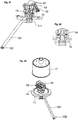
- the rotation mechanism 26 comprises a worm drive 29, formed from a worm gear 31 fixedly provided on base 12, and a screw gear 33 mounted on support 14.
- Screw gear 33 is connected via gear drive 34 to one of rolls 22.
- rotation of the rolls is transmitted via the gears to screw gear 33 which engages into worm gear 31 and, when being rotated, rotates support 14 with respect to base 12.
- the second embodiment allows to conveniently change the transmission ratio from rolls 22 to screw gear 33, as will be explained in the following with reference to Figure 13 .
- a small diameter container 1 with a small diameter coil 3 is shown.
- a large gear wheel 34a (please see Figure 13b ) is mounted on the axis on which roll 22 is mounted, with gear wheel 34a driving via an intermediate gear 34b a small gear wheel 34c drivingly connected to screw gear 33.
- a medium diameter container 1 with a medium diameter coil 3 is shown.
- a medium gear wheel 34a (please see Figure 13d ) is mounted on the axis on which roll 22 is mounted, with gear wheel 34a driving via an intermediate gear 34b a medium gear wheel 34c drivingly connected to screw gear 33.
- a large diameter container 1 with a large diameter coil 3 is shown.
- a small gear wheel 34a (please see Figure 13f ) is mounted on the axis on which roll 22 is mounted, with gear wheel 34a driving via an intermediate gear 34b a large gear wheel 34c drivingly connected to screw gear 33.
- Intermediate gear 34b is mounted in a sliding guide 35 which allows to quickly adapt the gear ratio to different pack dimensions (and the corresponding loop diameter inside the pack).
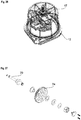
- a dust cover 17 closes device 10 so as to prevent dust and dirt from entering into device 10 and container 1.
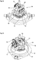
- a third embodiment of device 10 is shown in Figures 14 to 16 .
- the same reference numerals are being used, and reference is made to the above comments.
- first and second embodiments are "passive" devices in which the torsional force applied onto the wire is generated by the movement of the wire itself while in the second embodiment, the torsional force is actively generated by a motor.
- the third embodiment also uses a worm drive 29 formed from a worm gear 31 and a screw gear 33.
- worm gear 31 is fixedly connected to support 14 while screw gear 33 is mounted on base 12.
- a motor 40 is provided for driving (via a suitable reduction gear) screw gear 33.
- Rolls 22 are mounted on support 14 so as to be rotatable. They are biased with an adjustable force against each other.
- device 10 is controlled by a control which can be incorporated into wire feeder 6. It is also possible to implement the control separately.
- electric motor 40 When wire is withdrawn from container 1, electric motor 40 is operated so as to rotate wire clutching device 20 in the correct direction, thereby exerting a torsional force onto the wire.
- the amount of rotation of wire clutching device 20 per length unit of withdrawn wire can very conveniently be controlled via the control.
- the motor current of motor 40 can be controlled. Should excessive torsional forces are being built up in the wire, the motor current increases as a higher force is required to rotate the wire. In such event, the speed of operation of motor 40 can be reduced or stopped, or it is possible to deactivate biasing device 46 so that support 14 can freely rotate, thereby releasing the torsional tension in the wire. Subsequently, biasing device 46 can be reactivated, and operation of motor 40 can be resumed.
- the advantage of the third embodiment is that many of its components can be used both for a passive device as per the second embodiment and for the active device as per the third embodiment.
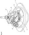
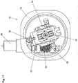
- FIG. 17 to 20 A fourth embodiment of device 10 is shown in Figures 17 to 20 .
- the same reference numerals are being used, and reference is made to the above comments.
- the general difference between the third embodiment and the fourth embodiment is that in the fourth embodiment, there is no intermeshing gear connection between the motor and the support (thus a positive connection) but a friction-based connection.
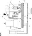
- Rotating mechanism 26 here comprises a drive motor 40 (an electric motor) which drives a drive wheel 42.
- Electric motor 40 together with drive wheel 42 are mounted on a carrier 44 which is pivotably connected to base 12.
- An application device 46 which is here in the form of a solenoid, is mounted on base 12 and is adapted for urging carrier 44 together with motor 40 and drive wheel 42 in a direction towards support 14. More specifically, application device 46 presses drive wheel 42 against a cylindrical driven surface 48 of support 14.
- Drive wheel 42 can be provided with an O-ring 50 or some other friction enhancing element in order to ensure that support 14 can be rotated by motor 40.
- Wire clutching device 20 of the fourth embodiment basically corresponds to the first embodiment in as it contains two rolls 22 which are urged against each other and against the wire passing through between the rolls.
- a biasing device 52 is here provided which allows changing the force with which the two rolls are pressed against each other.
- electric motor 40 When wire is withdrawn from container 1, electric motor 40 is operated so as to rotate wire clutching device 20 in the correct direction, thereby exerting the desired torsional force onto the wire. At the same time, biasing device 46 is activated so as to ensure that the power of motor 40 is transmitted to support 14.
- drive wheel 42 is connected to support 14 via a belt or rubber ring 60, thereby avoiding the need for a biasing device.
- Figures 22 to 30 is comparable to the embodiments of Figure 6 to 13 in that the movement of the wire through wire path 16 results in rotation of rolls 22, rotation of rolls 22 being in turn converted into a rotation of support 14 with respect to base 12.
- Gear drive 34 here comprises a shaft 70 on which one of rolls 22 and one of two gear wheels 72 which synchronize rotation of the two rolls 22 is mounted. Further, a gear wheel 74 is mounted on shaft 70, which meshes with additional gear wheel which finally entrain screw gear 32 which engages into worm gear 31.
- a torque limiter 76 is arranged in the torque transmission path between shaft 70 and gear wheel 34.
- torque limiter 76 prevents that excessive torque is transmitted from shaft 70 to gear wheel 74.
- Torque limiter 76 comprises a pressing ring 78, a spring 80 which is here a Belleville spring, an adjusting screw 82 and a locking mechanism 84.
- Gear wheel 74 is arranged adjacent a shoulder 84 of shaft 70.
- spring 80 is biased by adjusting screw 82 against pressing ring 78 which in turn presses gear wheel 74 against shoulder 84.
- a frictional force is created which allows transmission of a torque up to a predefined threshold from shaft 70 to gear wheel 74.
- Locking mechanism 86 allows to lock adjustment screw 82 in its position once the desired level of torque transmission is achieved.
- the torque limiter reliably ensures that no excessive torsional forces are created which then would be applied to the wire.
- Figures 31 to 38 show details of biasing device 52 which is used for changing the force with which rolls 22 are pressed against each other.
- Biasing device 52 serves for exerting a force onto a lever 53 which in turn results in a force which biases rolls 22 towards each other.
- Biasing device 52 comprises a traction rod 90 which is connected to lever 53 and on which a traction force can be applied by means of biasing device 52, with biasing device 52 being supported on an abutment 92.
- Abutment 92 has the form of a hook into which a wedge-shaped pressing part 94 engages (please see in particular Figure 31 to 37 ).
- a nut 96 is supported which is threaded onto traction rod 90.
- Nut 96 can be rotated by means of a hand wheel 98 which is connected to nut 96 by means of a cam mechanism 100.
- Cam mechanism 100 comprises a cam surface 102 which is provided in nut 96, and a transmission pin 104 which is supported in hand wheel 98 in a manner so as to be displaceable in a direction parallel to the axis of rotation of hand wheel 98.
- pressure pin 104 On its side facing away from cam surface 102, pressure pin 104 is engaged by a pressing washer 106 which in turn is biased towards pressure pin 104 by a stack of springs 108.
- Belleville springs are used.
- Springs 108 are capped in a preloaded condition by means of adjustment wheel 110, the axial position thereof being adjustable by means of a set screw 112. Set screw 112 is accessible after removal of a cap 114.
- Support 14 is here rotated by means of an arm 120 which has a wire receiving opening 122 arranged excentrically with respect to the axis of rotation of support 14.
- wire 2 is held in container 1 in the form of a coil, any traction force acting between the part of the wire entering between rolls 22 and the part of the wire received in the form of a coil, creates a force at wire receiving opening 122 which has a component directed in a peripheral direction.
- FIG. 44 and 45 An alternative to the embodiment of Figures 39 to 43 is shown in Figures 44 and 45 .
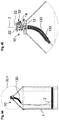
- the difference between the alternative embodiment and the previous embodiment is that a flexible wire guide 130 is used in the alternative, which is here held in a tube 132 so as to ensure that the end at which wire 2 exits from wire guide 130, is arranged excentrically with respect to the axis of rotation of support 14.
- device 10 has an electric motor 140 used for actively rotating rolls 22. Downstream of rollers 22, two sets of straightening rolls 142 are provided for straightening the wire. Rolls 22 driven by motor 140 serve for pushing the wire through the sets of straightening rolls 142.
- Motor 140 is provided with electric power by means of sliding contacts 144 arranged concentrically with respect to the axis of rotation of device 10.
Landscapes
- Engineering & Computer Science (AREA)
- Mechanical Engineering (AREA)
- Physics & Mathematics (AREA)
- Plasma & Fusion (AREA)
- General Engineering & Computer Science (AREA)
- Optics & Photonics (AREA)
- Unwinding Of Filamentary Materials (AREA)
- Basic Packing Technique (AREA)
- Winding, Rewinding, Material Storage Devices (AREA)
- Forwarding And Storing Of Filamentary Material (AREA)
- Tension Adjustment In Filamentary Materials (AREA)
- Coiling Of Filamentary Materials In General (AREA)
- Wire Processing (AREA)
Applications Claiming Priority (2)
| Application Number | Priority Date | Filing Date | Title |
|---|---|---|---|
| US16/747,046 US11174121B2 (en) | 2020-01-20 | 2020-01-20 | Device for imparting a torsional force onto a wire |
| US16/921,387 US11278981B2 (en) | 2020-01-20 | 2020-07-06 | Device for imparting a torsional force onto a wire |
Publications (2)
| Publication Number | Publication Date |
|---|---|
| EP3858531A1 true EP3858531A1 (fr) | 2021-08-04 |
| EP3858531B1 EP3858531B1 (fr) | 2022-11-09 |
Family
ID=74187134
Family Applications (1)
| Application Number | Title | Priority Date | Filing Date |
|---|---|---|---|
| EP21152057.2A Active EP3858531B1 (fr) | 2020-01-20 | 2021-01-18 | Dispositif pour transmettre une force de torsion sur un fil |
Country Status (10)
| Country | Link |
|---|---|
| US (1) | US11278981B2 (fr) |
| EP (1) | EP3858531B1 (fr) |
| JP (1) | JP7640991B2 (fr) |
| KR (1) | KR102986107B1 (fr) |
| CN (1) | CN113135464B (fr) |
| CA (1) | CA3104152A1 (fr) |
| DK (1) | DK3858531T3 (fr) |
| ES (1) | ES2934237T3 (fr) |
| HU (1) | HUE060717T2 (fr) |
| PL (1) | PL3858531T3 (fr) |
Families Citing this family (7)
| Publication number | Priority date | Publication date | Assignee | Title |
|---|---|---|---|---|
| US12240034B2 (en) * | 2022-01-03 | 2025-03-04 | Lincoln Global, Inc. | Wire straightening solution for bulk packaging |
| CN114348324B (zh) * | 2022-01-06 | 2023-07-14 | 宝武集团鄂城钢铁有限公司 | 一种防打捆线打结装置 |
| CN115594008B (zh) * | 2022-10-17 | 2023-10-24 | 河北博通橡塑制品有限公司 | 一种钢丝增强橡胶软管生产用钢丝放线机构 |
| CN116040409A (zh) * | 2023-03-20 | 2023-05-02 | 合肥神马科技集团有限公司 | 一种用于立式成缆机光纤放线的张力控制及储线功能装置 |
| CN116199034B (zh) * | 2023-04-06 | 2025-05-27 | 江西宏荣金属制品有限公司 | 一种铜线加工用放线器 |
| CN116460951B (zh) * | 2023-04-12 | 2025-08-29 | 哈尔滨工业大学 | 基于主动送纱的多丝束连续纤维增强混凝土3d打印装置及方法 |
| CN118048940B (zh) * | 2024-02-05 | 2025-02-21 | 中铁十一局集团有限公司 | 一种基坑施工底面高度测量装置及方法 |
Citations (6)
| Publication number | Priority date | Publication date | Assignee | Title |
|---|---|---|---|---|
| US5746380A (en) | 1996-03-20 | 1998-05-05 | Hyundai Welding & Metal Col, Ltd. | Device for preventing welding wire in a welding wire pail from tangling |
| KR20080013519A (ko) * | 2006-08-09 | 2008-02-13 | 기아자동차주식회사 | 와이어 회전 가이드 장치 |
| US7410111B2 (en) | 2006-06-16 | 2008-08-12 | Lincoln Global, Inc. | Guide ring for coiled wire |
| US7950523B2 (en) | 2006-03-30 | 2011-05-31 | Sidergas Spa | Retainer for a welding wire coil |
| WO2016022389A1 (fr) | 2014-08-06 | 2016-02-11 | Alcotec Wire Corporation | Unité d'assistance à l'alimentation flottante pour le gain de fil de soudage en vrac emballé |
| US10350696B2 (en) * | 2015-04-06 | 2019-07-16 | Awds Technologies Srl | Wire feed system and method of controlling feed of welding wire |
Family Cites Families (391)
| Publication number | Priority date | Publication date | Assignee | Title |
|---|---|---|---|---|
| US1468994A (en) | 1923-09-25 | Spooled wire | ||
| US318062A (en) | 1885-05-19 | warren | ||
| US617353A (en) | 1899-01-10 | Wire-coiling device | ||
| US2916944A (en) | 1959-12-15 | Device for the shifting of gear speeds in motor | ||
| US532565A (en) | 1895-01-15 | Rod-mill reel | ||
| US627722A (en) | 1897-08-25 | 1899-06-27 | Morgan Construction Co | Wire-reel. |
| US932808A (en) | 1909-04-17 | 1909-08-31 | Henry B Pelton | Paper-roll protector. |
| US1276117A (en) | 1917-06-13 | 1918-08-20 | Rogers Motor Lock Company | Flexible armored conduit. |
| US1508689A (en) | 1921-09-23 | 1924-09-16 | Gen Electric | Metallic arc welding |
| US1640368A (en) | 1926-12-13 | 1927-08-30 | Us Asbestos Company | Asbestos rope or wick package |
| US1821354A (en) | 1929-01-14 | 1931-09-01 | William H Meyer | Card mount for strings |
| US1907051A (en) | 1931-05-18 | 1933-05-02 | Wallace V Emery | Metallic welding electrode |
| US1936227A (en) | 1932-01-08 | 1933-11-21 | C And W Wire Container Company | Wire container |
| US2078161A (en) | 1934-03-21 | 1937-04-20 | Gen Electric | Gearing |
| US2027670A (en) | 1934-09-17 | 1936-01-14 | Marathon Paper Mills Co | Paper dispenser |
| US2059462A (en) | 1934-10-15 | 1936-11-03 | Kali Chemie Ag | Hexamethylenetetramine compound and the process of producing the same |
| US2027674A (en) | 1935-08-28 | 1936-01-14 | Marathon Paper Mills Co | Dispenser for folded sheets |
| US2329369A (en) | 1942-03-28 | 1943-09-14 | Ryan Aeronautical Company | Ball and socket joint |
| US2366101A (en) | 1943-08-18 | 1944-12-26 | Scott & Williams Inc | Yarn holding means |
| US2407746A (en) | 1944-12-02 | 1946-09-17 | Jesse E Johnson | Oscillating welding rod |
| US2457910A (en) | 1946-02-02 | 1949-01-04 | W L Maxson Corp | Flexible cable |
| US2483760A (en) | 1947-08-07 | 1949-10-04 | Sprinkle W Duncan | Electrical cable guide |
| US2477059A (en) | 1948-02-19 | 1949-07-26 | Deere Mfg Co | Dispensing mechanism for balers or the like |
| US2579131A (en) | 1948-12-10 | 1951-12-18 | Prec Steel Warehouse Inc | Dispensing container for coiled wire |
| US2580900A (en) | 1950-02-23 | 1952-01-01 | Mandel E Epstein | Package for twine, rope, or the like |
| US2713938A (en) | 1950-04-26 | 1955-07-26 | New Bedford Cordage Company | Rope package |
| US2752108A (en) | 1952-08-28 | 1956-06-26 | Driscoll Wire Company | Shipping container and paying-off device |
| US2694130A (en) | 1952-08-28 | 1954-11-09 | Posy A Howard | Arc welding wire guide |
| US2724538A (en) | 1952-09-10 | 1955-11-22 | Lewin Mathes Company | Packaging materials |
| US2679571A (en) | 1952-11-12 | 1954-05-25 | Utica Drop Forge & Tool Corp | Tip welder tool |
| US2849195A (en) | 1953-08-18 | 1958-08-26 | Driscoll Wire Company | Combination wire drawing and packaging device |
| US2974850A (en) | 1954-05-10 | 1961-03-14 | Owens Illinois Glass Co | Combined shipping container and dispensing receptacle |
| US2966258A (en) | 1955-03-01 | 1960-12-27 | Anaconda Wire & Cable Co | Packaging of wire |
| US2864565A (en) | 1955-03-07 | 1958-12-16 | Rea Magnet Wire Company Inc | Apparatus for dispensing wire |
| US2869719A (en) | 1955-08-17 | 1959-01-20 | Hubbard Spool Company | Wire processing and storage container |
| US2838922A (en) | 1955-09-07 | 1958-06-17 | Rosedale Knitting Company | Yarn control device |
| FR1146262A (fr) | 1956-03-24 | 1957-11-08 | Geoffrey-Delore Sa | Dispositif pour dévider en continu du fil à partir de fûts |
| US2984596A (en) | 1956-08-01 | 1961-05-16 | Minnesota Mining & Mfg | Label tape and method of applying same to a rubber article |
| DE1082215B (de) | 1957-11-30 | 1960-05-25 | Willy Aumann K G | Einrichtung zum Einspulen von Draht in Rosettenform in eine topffoermige, umlaufendeTrommel |
| US2880305A (en) | 1958-04-24 | 1959-03-31 | Union Carbide Corp | Welding wire feed |
| US2929576A (en) | 1958-08-25 | 1960-03-22 | Western Electric Co | Apparatus for distributing a strand into coil form |
| US3022415A (en) | 1958-07-16 | 1962-02-20 | Soudure Electr Autogene Sa | Gun and process for semi-automatic arc welding |
| FR1215111A (fr) | 1958-11-05 | 1960-04-14 | Sarazin & Cie | Procédé pour le bobinage et le dévidage de fils métalliques |
| GB880502A (en) | 1959-07-27 | 1961-10-25 | Vaughn Machinery Co | Wire packaging machine and method |
| DE1154624B (de) | 1960-08-12 | 1963-09-19 | Schering Ag | Haerter fuer Epoxyharze |
| US3185185A (en) | 1961-01-04 | 1965-05-25 | Sobel Metal Products Inc | Wire shaping apparatus |
| US3108180A (en) | 1961-02-07 | 1963-10-22 | Pullmax Ab | Welding electrode mouthpiece |
| US3119042A (en) | 1961-03-14 | 1964-01-21 | Chemetron Corp | Apparatus and method for feeding fabricated welding wire |
| US3096951A (en) | 1962-01-02 | 1963-07-09 | New Haven Wire & Cable Inc | Wire package and reel therefor |
| US3244347A (en) | 1964-02-20 | 1966-04-05 | Mead Corp | Corner post construction |
| US3344682A (en) | 1964-04-16 | 1967-10-03 | American Chain & Cable Co | Roller bearing push-pull cable |
| US3274850A (en) | 1964-11-04 | 1966-09-27 | Nazarene F Tascio | Flexible push-pull control cable |
| US3283121A (en) | 1965-07-21 | 1966-11-01 | Bernard Welding Equip Co | Arc welding gun |
| US3284608A (en) | 1965-09-29 | 1966-11-08 | Ralph C Mcdonald | Cleaner device for welding nozzle |
| US3352412A (en) | 1965-12-01 | 1967-11-14 | Micro Miniature Parts Corp | Package for flexible material |
| US3433504A (en) | 1966-07-05 | 1969-03-18 | Ventura Tool Co | Flexible connectors |
| DE1499056A1 (de) | 1966-12-21 | 1969-10-02 | Kabel Metallwerke Ghh | Anordnung zur Verlegung von strangfoermigem Gut,insbesondere von elektrischen Leitungen oder Draehten,im Innern von Vorratsfaessern |
| FR1516082A (fr) | 1967-01-06 | 1968-03-08 | Quenot & Cie Sarl | Procédé de freinage d'un ruban métallique d'instrument de mesures linéaires et instrument de mesures linéaires comportant application de ce procédé |
| US3576966A (en) | 1967-03-27 | 1971-05-04 | Air Reduction | Arc-welding in narrow gap |
| GB1229913A (fr) | 1967-07-27 | 1971-04-28 | ||
| US3478435A (en) | 1968-03-11 | 1969-11-18 | Edmond A Cook | Depth gauge for measuring the thickness of animal tissues |
| US3630425A (en) | 1968-04-20 | 1971-12-28 | Messer Griesheim Gmbh | Electrode wire advance for arc welding |
| US3567900A (en) | 1968-08-14 | 1971-03-02 | Battelle Development Corp | Welding method and apparatus |
| US3536888A (en) | 1968-08-15 | 1970-10-27 | Lawrence A Borneman | Splatter-free welding gun |
| US3491876A (en) | 1968-08-19 | 1970-01-27 | Hudson Wire Co | Wire package |
| US3565129A (en) | 1968-10-18 | 1971-02-23 | Manganese Steel Forge Co | Wire crimper |
| US3512635A (en) | 1968-10-31 | 1970-05-19 | Nat Standard Co | Wire let-off assembly wire coil package and combined wire coil package and let-off assembly |
| US3648920A (en) | 1968-11-20 | 1972-03-14 | Clevepak Corp | Tubular member |
| US3595277A (en) | 1969-07-07 | 1971-07-27 | Mckay Co | Wire straightener |
| DE1936100A1 (de) | 1969-07-16 | 1971-01-28 | Westfaelische Union Ag | Draht fuer die halb- und vollmaschinelle Schweissung |
| US3586222A (en) | 1969-08-28 | 1971-06-22 | Air Reduction | Speed control system for multiple motor feed of welding wire |
| GB1302055A (fr) | 1969-09-16 | 1973-01-04 | ||
| US3690567A (en) | 1970-03-09 | 1972-09-12 | Lawrence A Borneman | Electric arc welding gun having a nozzle with a removable metal liner to protect the nozzle from weld splatter |
| US3672655A (en) | 1970-03-12 | 1972-06-27 | Kenneth G Carter | Wire feeder |
| US3724249A (en) | 1970-03-28 | 1973-04-03 | Kloeckner Werke Ag | Method of and device for the coiling of metal tape or strip |
| GB1357912A (en) * | 1970-05-25 | 1974-06-26 | Hobart Brothers Co | Apparatus for moving wire |
| US3675499A (en) | 1970-09-18 | 1972-07-11 | Andre Marosy | Coupling |
| US3729092A (en) | 1971-03-12 | 1973-04-24 | W Marcell | Unwind support for coiled wire |
| DE2122958A1 (de) | 1971-05-10 | 1972-11-23 | Ernst Koch & Co, 5873 Ihmert | Vorrichtung zum Wickeln von Bunden, insbesondere Drahtbunden |
| DE2148348A1 (de) | 1971-09-28 | 1973-04-05 | Hoechst Ag | Verwendung von roten phosphor enthaltenden polymeren zur herstellung von flammwidrigen faeden und fasern |
| US3901425A (en) | 1971-06-04 | 1975-08-26 | Sooner Prod Co | Wire moving apparatus |
| BE791587A (fr) | 1971-11-19 | 1973-05-17 | Philips Nv | Dispositif d'entrainement et d'orientation d'un fil de soudage |
| JPS4913065A (fr) | 1972-03-21 | 1974-02-05 | ||
| US3815842A (en) | 1972-08-01 | 1974-06-11 | W Scrogin | Reel |
| US3823894A (en) | 1973-01-04 | 1974-07-16 | Anaconda Co | Strand package |
| FR2267255A1 (en) | 1974-04-10 | 1975-11-07 | Lafarge Emballage | Case for bulk liquid or powdered products - has polygonal section sleeve and stiffeners in square section container |
| US3939978A (en) | 1974-07-23 | 1976-02-24 | Ppg Industries, Inc. | Flat glass shipping container |
| GB1527592A (en) | 1974-08-05 | 1978-10-04 | Ici Ltd | Wound dressing |
| SE7513076L (sv) | 1974-11-22 | 1976-05-24 | Hitachi Shipbuilding Eng Co | Bagsvetsningsmetod och anordning herfor |
| US4102483A (en) | 1975-03-13 | 1978-07-25 | Osaka Denki Co., Ltd. | Method for feeding a welding wire |
| US4000797A (en) | 1975-06-02 | 1977-01-04 | Paul Ducanis | Noise-absorbing bar stock guide for screw machine |
| DE2525938C3 (de) | 1975-06-11 | 1979-07-05 | Messer Griesheim Gmbh, 6000 Frankfurt | Rollenführung zum Umlenken eines Schweißdrahtes |
| US4127590A (en) | 1975-10-14 | 1978-11-28 | Toyo Boseki Kabushiki Kaisha | Phosphorus-containing compounds |
| US4157436A (en) | 1975-10-14 | 1979-06-05 | Toyo Boseki Kabushiki Kaisha | Phosphorus-containing polyesters |
| US4188526A (en) | 1976-03-15 | 1980-02-12 | Babcock-Hitachi Kabushiki Kaisha | Narrow weld-groove welding process |
| US4044583A (en) | 1976-05-27 | 1977-08-30 | Wire Conveyor Belts, Inc. | Method and apparatus for making elongated flat wire coils |
| JPS53128195A (en) | 1977-04-15 | 1978-11-08 | Sanko Kaihatsu Kagaku Kenkiyuu | Flame retarder |
| US4097004A (en) | 1977-05-06 | 1978-06-27 | Ppg Industries, Inc. | Method and apparatus for unwinding roving packages from the inside |
| US4113795A (en) | 1977-07-05 | 1978-09-12 | Asahi-Dow Limited | Flame-retardant polyphenylene ether resin composition |
| SU793678A2 (ru) | 1977-07-07 | 1981-01-07 | Череповецкий металлургический завод | Способ укладки витков при смотке катанкиВ бОльшЕгРузНыЕ буНТы |
| JPS5435842A (en) | 1977-08-26 | 1979-03-16 | Nippon Steel Welding Prod Eng | Method for connecting wires in automatic welder |
| JPS5443856A (en) | 1977-09-14 | 1979-04-06 | Kobe Steel Ltd | Method and apparatus for coiling wire |
| US4161248A (en) | 1977-10-17 | 1979-07-17 | Universal Wire & Cable Co. Ltd. | Container for wire spool |
| US4172375A (en) | 1978-04-28 | 1979-10-30 | Kennecott Copper Corporation | Coiling system for metallic strands |
| US4171783A (en) | 1978-05-12 | 1979-10-23 | Phelps Dodge Industries, Inc. | Filament dereeling apparatus |
| JPS5912693B2 (ja) | 1978-05-24 | 1984-03-24 | 株式会社三光開発科学研究所 | 難燃剤 |
| JPS5554295A (en) | 1978-10-13 | 1980-04-21 | Nippon Steel Weld Prod & Eng Co Ltd | Connecting method of wire for automatic welding |
| JPS55112176A (en) | 1979-02-19 | 1980-08-29 | Osaka Denki Kk | Method and device for controlling wire feeding |
| GB2044812B (en) | 1979-03-28 | 1983-10-19 | Whellams G | Filament tensioning apparatus |
| JPS55156694A (en) | 1979-05-25 | 1980-12-05 | Nippon Steel Weld Prod & Eng Co Ltd | Small-diameter wire filler for welding |
| US4222535A (en) | 1979-07-16 | 1980-09-16 | Mossberg Hubbard, Division Of Wanskuck Company | Wire dereeling apparatus |
| JPS5623376A (en) | 1979-08-01 | 1981-03-05 | Nippon Steel Weld Prod & Eng Co Ltd | Arc welding method |
| DE2939316A1 (de) | 1979-09-28 | 1981-04-16 | Lucke-Apparate-Bau GmbH, 7947 Mengen | Garnwickelkoerper (kuchen) sowie verfahren und vorrichtung zu seiner herstellung |
| US4274607A (en) | 1979-12-03 | 1981-06-23 | Belden Corporation | Guide device for use in elongate filament dispensing package and the like |
| US4293103A (en) | 1979-12-17 | 1981-10-06 | Kotaro Tsukamoto | Metal wire winding apparatus |
| US4354487A (en) | 1980-05-12 | 1982-10-19 | Johnson & Johnson | Fiber/absorbent polymer composites and method of forming same |
| SE446717B (sv) | 1980-05-21 | 1986-10-06 | Skaltek Ab | Forfarande for astadkommande av en spolstomme |
| JPS57102471A (en) | 1980-12-12 | 1982-06-25 | Sumikin Yousetsubou Kk | Method of winding welding wire |
| JPS57111904A (en) | 1980-12-27 | 1982-07-12 | Horiba Ltd | Flexible cable |
| CA1169390A (fr) | 1980-12-29 | 1984-06-19 | Eiichiro Kawasaki | Contenant pour soudure filiforme |
| DE3269298D1 (en) | 1981-04-09 | 1986-04-03 | Robert Prunier | Welding devices using electrical discharges, especially for arc welding |
| JPS5835068A (ja) | 1981-08-27 | 1983-03-01 | Nippon Steel Weld Prod & Eng Co Ltd | 溶接用ワイヤの装填物 |
| JPS5870384A (ja) | 1981-09-24 | 1983-04-26 | Fujitsu Ltd | シリアルプリンタ制御方式 |
| GB2106816B (en) | 1981-10-05 | 1985-11-06 | Mitsubishi Heavy Ind Ltd | Narrow gap arc welding process and apparatus therefor |
| US4464919A (en) | 1981-12-09 | 1984-08-14 | Labbe Robert A | Wire straightener and method for straightening wire |
| US4392606A (en) | 1981-12-17 | 1983-07-12 | Westvaco Corporation | Pre-banded bulk pack container |
| US4531040A (en) | 1982-01-11 | 1985-07-23 | Mitsubishi Denki K.K. | Hot wire type arc welding torch and cable |
| US4429001A (en) | 1982-03-04 | 1984-01-31 | Minnesota Mining And Manufacturing Company | Sheet product containing sorbent particulate material |
| JPS58188126U (ja) | 1982-06-08 | 1983-12-14 | 株式会社井上ジャパックス研究所 | ワイヤカツト放電加工装置 |
| US4451014A (en) | 1982-08-11 | 1984-05-29 | Mossberg Industries, Inc. | Wire storing and dereeling apparatus |
| US4500315A (en) | 1982-11-08 | 1985-02-19 | Personal Products Company | Superthin absorbent product |
| EP0130191B1 (fr) | 1982-12-30 | 1986-05-14 | Eurosteel S.A. | Elements filiformes utilisables pour le renforcement de materiaux moulables en particulier pour le beton |
| GB8305797D0 (en) | 1983-03-02 | 1983-04-07 | Graham N B | Hydrogel-containing envelopes |
| US4546631A (en) | 1983-04-01 | 1985-10-15 | Foster Wheeler Energy Corporation | Roller mechanism for forming helical shapes |
| JPS59197386A (ja) | 1983-04-21 | 1984-11-08 | Matsushita Electric Ind Co Ltd | リ−ド線溶接用電極 |
| JPS59229287A (ja) | 1983-06-10 | 1984-12-22 | Nippon Steel Weld Prod & Eng Co Ltd | 溶接用ワイヤの装填物 |
| JPS59232669A (ja) | 1983-06-13 | 1984-12-27 | Kobe Steel Ltd | 溶接用ワイヤのキヤスト形成方法 |
| JPS6021181A (ja) | 1983-07-18 | 1985-02-02 | Mitsubishi Heavy Ind Ltd | 溶接ワイヤ−の屈曲方法 |
| US4540225A (en) | 1983-09-07 | 1985-09-10 | Arcair Company | Swivel cable coupling for an air carbon-arc cutting and gouging torch |
| JPS6082276A (ja) | 1983-10-06 | 1985-05-10 | Kobe Steel Ltd | パツク入り溶接用ワイヤのワイヤ継ぎ方法 |
| JPS6082275A (ja) | 1983-10-06 | 1985-05-10 | Kobe Steel Ltd | パツク入り溶接用ワイヤのワイヤ継ぎ方法 |
| JPS60184422A (ja) | 1984-02-29 | 1985-09-19 | Kobe Steel Ltd | 溶接用ワイヤのキヤスト形成方法 |
| JPS60223664A (ja) | 1984-04-20 | 1985-11-08 | Nippon Steel Weld Prod & Eng Co Ltd | 溶接用ワイヤの装填方法 |
| JPH068371B2 (ja) | 1985-01-11 | 1994-02-02 | 旭化成工業株式会社 | 難燃性樹脂組成物 |
| US4582198A (en) | 1985-02-19 | 1986-04-15 | Essex Group, Inc. | Wire shipping and dispensing package |
| US5215338A (en) | 1985-04-09 | 1993-06-01 | Tsubakimoto Chain Co. | Flexible supporting sheath for cables and the like |
| JPS61293674A (ja) | 1985-06-21 | 1986-12-24 | Toyota Motor Corp | ア−ク溶接機 |
| JPS629774A (ja) | 1985-07-09 | 1987-01-17 | Toyota Motor Corp | ア−ク溶接機 |
| JPS62174228A (ja) | 1985-10-18 | 1987-07-31 | Nippon Ester Co Ltd | コポリエステル |
| JPS62111872A (ja) | 1985-11-11 | 1987-05-22 | Kobe Steel Ltd | 溶接用ワイヤの引出し方法 |
| US4623063A (en) | 1986-01-29 | 1986-11-18 | Balkin Michael L | Fibreboard container for coil material |
| FR2595674B1 (fr) | 1986-03-14 | 1989-03-03 | Senelonge Henri | Machine pour la realisation de bottes de fils sans torsion |
| DE3609839A1 (de) | 1986-03-22 | 1987-09-24 | Bosch Gmbh Robert | Vorrichtung zum selbsttaetigen ausloesen von insassenschutzvorrichtungen bei einem unfall |
| JP2514932B2 (ja) | 1986-06-06 | 1996-07-10 | 株式会社古河テクノマテリアル | 形状記憶合金線材の直線形状記憶処理方法 |
| KR890002086B1 (ko) | 1986-09-12 | 1989-06-16 | 주식회사 코오롱 | 함인 질소계 난연제의 제조방법 |
| JPS63147781A (ja) | 1986-12-09 | 1988-06-20 | Kobe Steel Ltd | 溶接用パツクワイヤ |
| US4868366A (en) | 1986-12-16 | 1989-09-19 | Joseph Beresford C | Arc welding capable of multi-mode welding |
| SU1412830A1 (ru) | 1987-02-11 | 1988-07-30 | Предприятие П/Я М-5481 | Способ формировани бунта катанки на моталке с вертикальным намоточным валом |
| JPH0672301B2 (ja) | 1987-05-20 | 1994-09-14 | 川崎製鉄株式会社 | 差圧シ−ル装置 |
| GB8714578D0 (en) | 1987-06-22 | 1987-07-29 | British Telecomm | Fibre winding |
| US4795482A (en) | 1987-06-30 | 1989-01-03 | Union Carbide Corporation | Process for eliminating organic odors and compositions for use therein |
| US4855179A (en) | 1987-07-29 | 1989-08-08 | Arco Chemical Technology, Inc. | Production of nonwoven fibrous articles |
| US5061259A (en) | 1987-08-19 | 1991-10-29 | The Procter & Gamble Company | Absorbent structures with gelling agent and absorbent articles containing such structures |
| FR2623432B1 (fr) | 1987-11-20 | 1990-04-20 | Framatome Sa | Dispositif de decoupage par etincelage de la paroi d'une piece tubulaire |
| JPH01240222A (ja) | 1988-03-19 | 1989-09-25 | Fanuc Ltd | ワイヤ回収箱 |
| JPH041113Y2 (fr) | 1988-10-06 | 1992-01-14 | ||
| US4949567A (en) | 1988-11-04 | 1990-08-21 | Corbin Edward W | Apparatus and method for control of wire cast and helix |
| US5227314A (en) | 1989-03-22 | 1993-07-13 | At&T Bell Laboratories | Method of making metal conductors having a mobile inn getterer therein |
| US4918286A (en) | 1989-05-01 | 1990-04-17 | Boyer Robert W | Method and apparatus for cleaning and lubricating a metal inert gas welding gun |
| US5100397A (en) | 1989-06-14 | 1992-03-31 | Mcneil-Ppc, Inc. | Absorbent mixture |
| US4974789A (en) | 1989-06-29 | 1990-12-04 | Trimedyne Laser Systems, Inc. | Dispensing package for a fiber-optic device |
| GB8915769D0 (en) | 1989-07-10 | 1989-08-31 | Bwe Ltd | Continuous extrusion apparatus |
| US5165217A (en) | 1989-09-12 | 1992-11-24 | Ethicon, Inc. | One piece channel suture packages |
| JPH03264169A (ja) | 1990-03-13 | 1991-11-25 | Daido Steel Co Ltd | 溶接ワイヤ収納容器 |
| US5051539A (en) | 1990-06-07 | 1991-09-24 | Dave A. Leathers | Swivel joint for cover of fluid-cooled welding cable |
| US5078269A (en) | 1990-06-07 | 1992-01-07 | Group Dekko International, Inc. | Wire shipping and dispensing container |
| JPH04112169A (ja) | 1990-08-29 | 1992-04-14 | Nippon Steel Weld Prod & Eng Co Ltd | 溶接用ワイヤの抑え部材 |
| JPH04133973A (ja) | 1990-09-21 | 1992-05-07 | Nippon Steel Weld Prod & Eng Co Ltd | 溶接用ワイヤ収納ペイルパック |
| US5109983A (en) | 1991-01-28 | 1992-05-05 | Minnesota Mining And Manufacturing Company | Package for an optical fiber jumper |
| JP2781669B2 (ja) | 1991-02-28 | 1998-07-30 | 日鐵溶接工業株式会社 | 溶接用ワイヤの装填方法 |
| US5105943A (en) | 1991-05-14 | 1992-04-21 | Sonoco Products Company | Wire coil package |
| CA2071419C (fr) | 1991-06-18 | 1996-03-19 | William Dimmett Cooper | Rondelle retenue pour contenant a bobine de fil a souder |
| US5314111A (en) | 1991-09-28 | 1994-05-24 | Kabushiki Kaisha Kobe Seiko Sho | Packaging box and sheet for packaging box |
| JP3155786B2 (ja) | 1991-10-11 | 2001-04-16 | 日立ビアメカニクス株式会社 | 半自動アーク溶接機 |
| JPH05178538A (ja) | 1991-12-27 | 1993-07-20 | Daido Steel Co Ltd | ペイルパック用引出し治具 |
| US5201419A (en) | 1992-02-21 | 1993-04-13 | Laclede Chain Manufacturing Company | Chain container |
| GB9204268D0 (en) | 1992-02-28 | 1992-04-08 | M Y Humberside Packaging Limit | Stackable container |
| US5205412A (en) | 1992-04-08 | 1993-04-27 | Aurex, S.A. De C.V. | Recyclable package for a stack of rolls of magnetic tape |
| US5372269A (en) | 1992-04-23 | 1994-12-13 | Creative Thermal Vac Manufacturing, Inc. | Multipurpose container and display sign |
| CA2068828C (fr) | 1992-05-15 | 1998-12-22 | Michel Lanoue | Devidoir de fil, de cable ou autre article assimile |
| US5330754A (en) | 1992-06-29 | 1994-07-19 | Archana Kapoor | Membrane-associated immunogens of mycobacteria |
| IL102935A (en) * | 1992-08-25 | 1996-10-31 | Planetics Welding Systems Ltd | Palmetric feed heads |
| JPH06107377A (ja) | 1992-09-28 | 1994-04-19 | Bridgestone Bekaert Steel Code Kk | 金属線条体用リ−ル |
| IT231566Y1 (it) | 1993-02-23 | 1999-08-04 | Sidergas Srl | Contenitore di imballaggio e di svolgimento di una matassa di filo metallico |
| US5629377A (en) | 1993-03-10 | 1997-05-13 | The Dow Chemical Company | Water absorbent resin particles of crosslinked carboxyl containing polymers and method of preparation |
| US5368245A (en) | 1993-07-20 | 1994-11-29 | Communication Cable, Inc. | Two-piece pay-out tube |
| JP2783125B2 (ja) | 1993-07-23 | 1998-08-06 | 株式会社デンソー | ワイヤボンディング方法 |
| GB9401604D0 (en) | 1994-01-27 | 1994-03-23 | Mitchell Packaging Limited | Containers and container systems |
| US5553810A (en) | 1994-02-23 | 1996-09-10 | The Lincoln Electric Company | Covers for welding wire reels |
| JPH07247058A (ja) | 1994-03-08 | 1995-09-26 | Kobe Steel Ltd | 溶接用ワイヤの装填物及び溶接ワイヤ用のペイル容器 |
| US5599335A (en) | 1994-03-29 | 1997-02-04 | The Procter & Gamble Company | Absorbent members for body fluids having good wet integrity and relatively high concentrations of hydrogel-forming absorbent polymer |
| CA2145459C (fr) | 1994-04-26 | 1999-01-12 | Terence M. Shore | Tete de laminoir ultrarapide |
| DE4418319C3 (de) | 1994-05-26 | 2001-08-09 | Stockhausen Chem Fab Gmbh | Schichtförmig aufgebauter Körper zur Absorption von Flüssigkeiten sowie seine Herstellung und seine Verwendung |
| IT1267251B1 (it) | 1994-06-07 | 1997-01-28 | Danieli Off Mecc | Dispositivo per il deposito asimmetrico delle spire |
| US5714156A (en) | 1994-07-05 | 1998-02-03 | The Procter & Gamble Company | Absorbent gelling material comprising a dry mixture of at least two types of hydrogel-forming particles and method for making the same |
| US5586733A (en) | 1994-07-21 | 1996-12-24 | Bridgestone Metalpha Corporation | Take-up reel for metallic filaments |
| JPH0840642A (ja) | 1994-07-27 | 1996-02-13 | Nippon Steel Weld Prod & Eng Co Ltd | 溶接用ワイヤの装填物 |
| DE4436079A1 (de) | 1994-10-10 | 1996-04-11 | Hoechst Ag | Verfahren zur Herstellung phosphorhaltiger Dicarbonsäuren |
| JPH08150492A (ja) | 1994-11-24 | 1996-06-11 | Kawasaki Steel Corp | 溶接用ワイヤ |
| DE59502367D1 (de) | 1994-12-07 | 1998-07-02 | Wafios Maschinen Wagner | Verfahren und vorrichtung zur optimierten herstellung von schraubenfedern auf federwindeautomaten |
| JP2793970B2 (ja) | 1995-03-30 | 1998-09-03 | 株式会社神戸製鋼所 | エレクトロスラグ溶接用ワイヤ装填物 |
| US5585013A (en) | 1995-04-07 | 1996-12-17 | Truty; Thomas J. | Electrode guide |
| US5665801A (en) | 1995-06-20 | 1997-09-09 | Industrial Technology Research Institute | High molecular weight polyester flame retardant and process for preparing the same |
| US5530088A (en) | 1995-06-21 | 1996-06-25 | Industrial Technology Research Institute | Heat resistant phosphorus-containing polymeric flame retardant and process for preparing the same |
| DE19522876C1 (de) | 1995-06-23 | 1996-11-14 | Schill & Seilacher | Verfahren zur Herstellung eines DOP-haltigen Gemisches und dessen Verwendung |
| GB9602580D0 (en) | 1996-02-08 | 1996-04-10 | Dual Voltage Ltd | Plastics flexible core |
| JP3264169B2 (ja) | 1996-02-20 | 2002-03-11 | 日本鋼管株式会社 | 廃棄プラスチックの比重分離装置 |
| US5816466A (en) | 1996-04-19 | 1998-10-06 | The Lincoln Electric Company | Wire feeding apparatus |
| DE19619095A1 (de) | 1996-05-06 | 1997-11-13 | Schill & Seilacher | Flammfeste Epoxidharze und Flammschutzmittel für Epoxidharze |
| US5739704A (en) | 1996-07-22 | 1998-04-14 | Bimba Manufacturing Company | Logic selection circuit |
| IT1286954B1 (it) | 1996-07-24 | 1998-07-24 | C I F E S P A | Dispositivo per la frenatura dello svolgimento di filo metallico in matassa alloggiato in fusto |
| USRE40351E1 (en) | 1996-07-24 | 2008-06-03 | Lincoln Global, Inc. | Mechanism for braking the unwinding of a bundle of metallic wire housed in a drum |
| JP2969259B2 (ja) | 1996-07-25 | 1999-11-02 | 三洋化成工業株式会社 | 繊維用処理剤 |
| US5758834A (en) | 1996-08-20 | 1998-06-02 | Illinois Tool Works Inc. | Welding wire storage and shipping container |
| US5738209A (en) | 1996-12-23 | 1998-04-14 | General Motors Corporation | Cable storage container |
| CA2194937A1 (fr) | 1997-01-13 | 1998-07-13 | John Craig | Poste mobile de soudage automatique d'oleoducs et systeme de controle de qualite connexe |
| SE9700666D0 (sv) | 1997-02-24 | 1997-02-24 | Iro Ab | Fadenliefergerät und fadenbremse |
| US5990377A (en) | 1997-03-21 | 1999-11-23 | Kimberly-Clark Worldwide, Inc. | Dual-zoned absorbent webs |
| ATE252031T1 (de) | 1997-05-20 | 2003-11-15 | Esab Ab | Verpackungsbehälter mit mittel zum abspulen für eine schweissdrahtspule |
| US5988370A (en) | 1997-06-23 | 1999-11-23 | Roemer; Donald A. | Corrugated fibreboard container with at least one hinged side and blanks for assembling said container |
| JP3045774U (ja) | 1997-07-30 | 1998-02-13 | 金井 宏之 | 金属線条体巻装用リール |
| US6638621B2 (en) | 2000-08-16 | 2003-10-28 | Lyotropic Therapeutics, Inc. | Coated particles, methods of making and using |
| US5819934A (en) | 1997-10-27 | 1998-10-13 | The Lincoln Electric Company | Wire transport drum |
| US6072101A (en) | 1997-11-19 | 2000-06-06 | Amcol International Corporation | Multicomponent superabsorbent gel particles |
| US5921391A (en) | 1997-11-26 | 1999-07-13 | Stone Container Corporation | Container for storing and transporting wire, cord and the like |
| CN1095801C (zh) | 1998-01-29 | 2002-12-11 | 日铁溶接工业株式会社 | 焊接用焊丝的包装物 |
| US5971308A (en) | 1998-03-04 | 1999-10-26 | National-Standard Company | Wire transfer assembly |
| AT409239B (de) | 1998-05-13 | 2002-06-25 | Fronius Schweissmasch | Verfahren zum steuern eines schweissgerätes und steuervorrichtung hierfür |
| FR2779190B1 (fr) | 1998-05-29 | 2000-08-18 | Cba | Cable pour commande a distance |
| GB2332451A (en) | 1998-06-05 | 1999-06-23 | Welding Supplies | Delivery guide for wire |
| SE513139C2 (sv) | 1998-11-20 | 2000-07-10 | Derman Ab K G | Rullningslager |
| US6019303A (en) | 1998-12-16 | 2000-02-01 | Lincoln Global, Inc. | Method and apparatus for packing wire in a storage drum |
| JP2000202630A (ja) | 1999-01-13 | 2000-07-25 | Daido Steel Co Ltd | 溶接ワイヤ充填ペイル |
| JP2000225468A (ja) | 1999-02-04 | 2000-08-15 | Daido Steel Co Ltd | 溶接ワイヤ充填ペイル |
| US6016911A (en) | 1999-02-19 | 2000-01-25 | Chen; Hua-Mei | Package for a reel of wire |
| JP3071774B1 (ja) | 1999-02-25 | 2000-07-31 | 高麗溶接棒ジャパン株式会社 | 送給性の優れた溶接用ソリッドワイヤ |
| DE19909214A1 (de) | 1999-03-03 | 2000-09-07 | Basf Ag | Wasserabsorbierende, schaumförmige, vernetzte Polymerisate mit verbesserter Verteilungswirkung, Verfahren zu ihrer Herstellung und ihre Verwendung |
| DE19910128C1 (de) | 1999-03-04 | 2001-01-04 | Aesculap Meditec Gmbh | Schutzhülle für Lichtleiter |
| JP4154064B2 (ja) | 1999-03-16 | 2008-09-24 | 株式会社東芝 | マグネトロン部品の製造方法 |
| DE19915035C2 (de) | 1999-04-01 | 2001-08-09 | Kabelschlepp Gmbh | Leitungsführungselement zum Führen wenigstens einer Leitung |
| DE69910357T2 (de) | 1999-05-31 | 2004-04-29 | C.I.F.E. S.R.L., Chiusi Della Verna | Aus Karton hergestellte Faltschachtel zur Aufnahme und Abgabe von Draht |
| US6150632A (en) | 1999-06-10 | 2000-11-21 | Tregaskiss, Ltd. | Electronic lock-on wire feed switch device |
| US7032814B2 (en) | 1999-06-21 | 2006-04-25 | Lincoln Global, Inc. | Coded welding consumable |
| US6247664B1 (en) | 1999-06-25 | 2001-06-19 | Siecor Operations, Llc | Reel monitor devices and methods of using the same |
| US6236017B1 (en) | 1999-07-01 | 2001-05-22 | Bechtel Bwxt Idaho, Llc | Method and apparatus for assessing weld quality |
| JP3723381B2 (ja) | 1999-07-15 | 2005-12-07 | 株式会社神戸製鋼所 | ペイル容器入り金属線材の収納方法 |
| DE19933901A1 (de) | 1999-07-22 | 2001-02-01 | Clariant Gmbh | Flammschutzmittel-Kombination |
| US6301944B1 (en) | 1999-09-22 | 2001-10-16 | General Electric Company | Methods of fabricating mechanized welding wire |
| US6245880B1 (en) | 1999-10-08 | 2001-06-12 | Toyo Boseki Kabushiki Kaisha | Organophosphorous composition, method of producing organophosphorous compound, polyester composition and method of producing the same |
| US6753454B1 (en) | 1999-10-08 | 2004-06-22 | The University Of Akron | Electrospun fibers and an apparatus therefor |
| KR100343927B1 (ko) | 1999-10-28 | 2002-07-19 | 주식회사 효성 | 스틸코드 권취용 스풀 |
| AT411032B (de) | 1999-11-19 | 2003-09-25 | Fronius Schweissmasch Prod | Verfahren und vorrichtung zum überwachen einer förderkraft |
| JP2001158567A (ja) | 1999-12-01 | 2001-06-12 | Daido Steel Co Ltd | 溶接ワイヤの引き出し方法とこれに用いる捻り付与装置 |
| DE19958697A1 (de) | 1999-12-06 | 2001-06-07 | Basf Ag | Absorbierende Zubereitung |
| TW490474B (en) | 2000-01-04 | 2002-06-11 | Nat Science Council | Phosphorus group containing flame retardant hardener, advanced epoxy resins and cured epoxy resins thereof |
| US6417425B1 (en) | 2000-02-01 | 2002-07-09 | Basf Corporation | Absorbent article and process for preparing an absorbent article |
| DE10006592A1 (de) | 2000-02-09 | 2001-08-23 | Schill & Seilacher | Latente Kombinationsverbindungen und latente Ammoniumsalze aus Epoxidharzhärter und Flammschutzmittel sowie daraus hergestellte Epoxidharz-Systeme und -Produkte |
| US6800056B2 (en) | 2000-04-03 | 2004-10-05 | Neoguide Systems, Inc. | Endoscope with guiding apparatus |
| JP2001323268A (ja) | 2000-05-16 | 2001-11-22 | Sanko Kk | 有機リン系難燃剤、その製造方法及びそれらを含有する樹脂組成物 |
| US6296118B1 (en) | 2000-06-07 | 2001-10-02 | John W. Speck | Stackable, nestable, and reusable container for storing and dispensing elongated materials, and method of using same |
| KR100359482B1 (ko) | 2000-06-28 | 2002-10-31 | 고려용접봉 주식회사 | 송급성이 우수한 아크용접용 와이어 및 와이어의 신선방법 |
| JP3782289B2 (ja) | 2000-07-06 | 2006-06-07 | トキコーポレーション株式会社 | 形状記憶合金の処理方法および形状記憶合金 |
| US6340522B1 (en) | 2000-07-13 | 2002-01-22 | Wr Grace & Co.-Conn. | Three-dimensional twisted fibers and processes for making same |
| CZ2003176A3 (cs) | 2000-07-24 | 2003-06-18 | Dov Global Technologies Inc. | Prostředky z termoplastického superabsorpčního polymerního blendu a jejich příprava |
| DE10043706A1 (de) | 2000-09-04 | 2002-04-25 | Stockhausen Chem Fab Gmbh | Pulverförmige, vernetzte, wässrige Flüssigkeiten sowie Blut absorbierende Polymere, Verfahren zu ihrer Herstellung und ihre Verwendung |
| US6720389B2 (en) | 2000-09-20 | 2004-04-13 | Nippon Shokubai Co., Ltd. | Water-absorbent resin and production process therefor |
| US8007884B2 (en) | 2000-10-25 | 2011-08-30 | Synergistic Ventures, Inc. | Irrigation, erosion control, root growth control and clean-up techniques |
| US6409116B1 (en) | 2000-10-30 | 2002-06-25 | Maurice H. Brown | Rapidly adjustable wire control mechanism |
| IT1319676B1 (it) | 2000-12-05 | 2003-10-23 | Ausimont Spa | Metodo per rimuovere acqua da superfici. |
| US6530511B2 (en) | 2001-02-13 | 2003-03-11 | Medallion Technology, Llc | Wire feed mechanism and method used for fabricating electrical connectors |
| JP2002308528A (ja) | 2001-04-17 | 2002-10-23 | Higuchi Shoten:Kk | 線条材の撚り戻し装置 |
| SE518955C2 (sv) | 2001-05-17 | 2002-12-10 | Metso Paper Inc | Anordning och sätt att haspla av tråd från en trådspole |
| SE517147C2 (sv) | 2001-05-18 | 2002-04-23 | Esab Ab | Anordning vid svetstrådsmatning, trådorienteringslöpare, metod och användning |
| US6708864B2 (en) | 2001-06-15 | 2004-03-23 | Lincoln Global, Inc. | “S” shaped cast in wire |
| US6464077B1 (en) | 2001-07-06 | 2002-10-15 | Faithful Engineering Products Co., Ltd. | Container for thread and wire |
| US6636776B1 (en) | 2001-07-09 | 2003-10-21 | Lincoln Global, Inc. | System and method for managing welding procedures and welding resources |
| US6564943B2 (en) | 2001-07-13 | 2003-05-20 | Lincoln Global, Inc. | Container for welding wire |
| JP3812381B2 (ja) | 2001-07-30 | 2006-08-23 | 松下電器産業株式会社 | 溶接ワイヤ送給装置 |
| US6649870B1 (en) | 2001-08-31 | 2003-11-18 | Lincoln Global, Inc. | System and method facilitating fillet weld performance |
| US6648141B2 (en) | 2001-09-04 | 2003-11-18 | Lincoln Global, Inc. | Packaging for containing and dispensing large quantities of wire |
| WO2003022316A1 (fr) | 2001-09-07 | 2003-03-20 | Basf Aktiengesellschaft | Hydrogels superabsorbants presentant une repartition granulometrique determinee |
| DE10202839A1 (de) | 2002-01-24 | 2003-08-07 | Basf Ag | Hydrogele bestimmter Teilchengrössenverteilung |
| ITTO20010894A1 (it) | 2001-09-19 | 2003-03-19 | Sidergas Srl | Contenitore di un filo per saldatura. |
| US6715608B1 (en) | 2001-11-06 | 2004-04-06 | Lincoln Global, Inc. | Package for welding wire |
| US6872275B2 (en) | 2001-12-14 | 2005-03-29 | Kimberly-Clark Worldwide, Inc. | Process for adding superabsorbent to a pre-formed fibrous web via in situ polymerization |
| US6745899B1 (en) | 2002-02-25 | 2004-06-08 | Lincoln Global, Inc. | Wire payout |
| US7156334B1 (en) | 2002-03-01 | 2007-01-02 | X-Spooler, Inc. | Pay-out tube |
| US6648376B2 (en) | 2002-03-29 | 2003-11-18 | Showertek, Inc. | Flexible sectioned arm with internal overbending-prevention sleeves |
| US7017742B2 (en) | 2002-04-10 | 2006-03-28 | Hobart Brothers Company, | Recyclable container adapted for movement by a lifting device and method for making same |
| ITMI20020898A1 (it) | 2002-04-24 | 2003-10-24 | Isaf S P A | Contenitore per matassa di filo per saldatura dotabile di dispositivoper collegare allo stesso una guaina di alimentazione del filo ad una |
| US6547176B1 (en) | 2002-06-04 | 2003-04-15 | Air Liquide Canada Inc. | Wire unwinding controller |
| CN1323793C (zh) | 2002-06-17 | 2007-07-04 | 现代综合金属株式会社 | 防焊丝缠结装置 |
| JP2004025242A (ja) | 2002-06-26 | 2004-01-29 | Nippon Steel & Sumikin Welding Co Ltd | ガスシールドアーク溶接用ワイヤ |
| JP2004025243A (ja) | 2002-06-26 | 2004-01-29 | Nippon Steel & Sumikin Welding Co Ltd | 溶接用ワイヤの送給方法 |
| ITMI20021567A1 (it) | 2002-07-16 | 2004-01-16 | New Ermes Europe Spa | Giunto snodato per un elettrodomestico ed elettrodomestico comprendente tale giunto |
| JP4272393B2 (ja) | 2002-08-07 | 2009-06-03 | 互応化学工業株式会社 | 水性難燃性ポリエステル樹脂の製造方法 |
| KR100443728B1 (ko) | 2002-09-07 | 2004-08-09 | 박종근 | 용접용 와이어 패일팩에 설치되는 누름판 |
| US7411013B2 (en) | 2002-12-27 | 2008-08-12 | Polyplastics Co., Ltd. | Flame-retardant resin composition |
| US7563840B2 (en) | 2003-01-06 | 2009-07-21 | Toray Plastics (America), Inc. | Flame retardant polyester resin composition and articles formed thereform |
| JP3923441B2 (ja) | 2003-03-25 | 2007-05-30 | 三光株式会社 | 難燃性合成樹脂組成物 |
| US6913145B2 (en) | 2003-04-15 | 2005-07-05 | Lincoln Global, Inc. | Welding wire container with ribbed walls and a mating retainer ring |
| CN1788053A (zh) | 2003-04-17 | 2006-06-14 | 互应化学工业株式会社 | 阻燃环氧树脂组合物、包含该组合物的预浸料、层压体和印制线路板 |
| US20040211851A1 (en) | 2003-04-24 | 2004-10-28 | Lincoln Global , Inc. | Welding wire payout drum |
| US20040241333A1 (en) | 2003-05-30 | 2004-12-02 | The Procter & Gamble Company | Composition and process for coating a substrate |
| JP4471975B2 (ja) | 2003-06-30 | 2010-06-02 | ザ プロクター アンド ギャンブル カンパニー | コーティングされたナノファイバーのウェブ |
| JP4393513B2 (ja) | 2003-06-30 | 2010-01-06 | ザ プロクター アンド ギャンブル カンパニー | ナノファイバーウェブにおける微粒子 |
| EP2221068A2 (fr) | 2003-06-30 | 2010-08-25 | The Procter & Gamble Company | Structures absorbantes comprenant des articles polymères super-absorbants revêtus |
| US6977357B2 (en) | 2003-07-09 | 2005-12-20 | Lincoln Global, Inc. | Welding wire positioning system |
| US7178755B2 (en) | 2003-07-30 | 2007-02-20 | Lincoln Global, Inc | Retainer ring for wire package |
| US7533906B2 (en) | 2003-10-14 | 2009-05-19 | Water Pik, Inc. | Rotatable and pivotable connector |
| AT500755B8 (de) | 2003-10-23 | 2007-02-15 | Fronius Int Gmbh | Drahtförderung mit konstantem moment |
| SG112938A1 (en) | 2003-12-10 | 2005-07-28 | Kobe Steel Ltd | Welding wire container |
| KR100560824B1 (ko) | 2003-12-12 | 2006-03-13 | 고려용접봉 주식회사 | 재활용이 가능한 용접 와이어용 페일팩 |
| DE10360466A1 (de) | 2003-12-22 | 2005-07-14 | Sidergas Spa | Abdeckung für einen Schweißdrahtbehälter |
| US9579742B2 (en) | 2006-01-09 | 2017-02-28 | Lincoln Global, Inc. | Series arc welder |
| AT413659B (de) | 2004-01-26 | 2006-04-15 | Fronius Int Gmbh | Schweissdraht-speichervorrichtung |
| US8225977B2 (en) | 2004-03-08 | 2012-07-24 | Lincoln Global, Inc. | Wire feeder with run-in control |
| US7180029B2 (en) | 2004-04-16 | 2007-02-20 | Illinois Tool Works Inc. | Method and system for a remote wire feeder where standby power and system control are provided via weld cables |
| US9012807B2 (en) | 2004-04-16 | 2015-04-21 | Illinois Tool Works Inc. | Remote wire feeder using binary phase shift keying to modulate communications of command/control signals to be transmitted over a weld cable |
| US8592724B2 (en) | 2004-04-16 | 2013-11-26 | Illinois Tool Works Inc. | Remote wire feeder using binary phase shift keying to modulate communications of command/control signals to be transmitted over a weld cable |
| US7191968B2 (en) | 2004-05-19 | 2007-03-20 | National Standard Company | System for handling welding wire and method of handling welding wire using the system |
| US7339135B2 (en) | 2004-06-04 | 2008-03-04 | Illinois Tool Works Inc. | Welding arc stabilization process |
| US20060070987A1 (en) | 2004-09-30 | 2006-04-06 | Lincoln Global, Inc. | Monitoring device for welding wire supply |
| US7220942B2 (en) | 2004-09-30 | 2007-05-22 | Lincoln Global, Inc. | Feeder for endless welding wire |
| US7377388B2 (en) | 2004-11-15 | 2008-05-27 | Lincoln Global, Inc. | Welding wire package |
| ATE518900T1 (de) | 2004-11-24 | 2011-08-15 | Toyo Boseki | Flammwidrige polyester und herstellungsverfahren dafür |
| US7700893B2 (en) | 2004-12-22 | 2010-04-20 | Illinois Tool Works Inc. | System and method for calibrating wire feeder motor control |
| US20060138116A1 (en) | 2004-12-27 | 2006-06-29 | Lincoln Global, Inc. | Thread control for welding wire |
| DE602005020412D1 (de) | 2005-01-11 | 2010-05-20 | Procter & Gamble | Dichte Verbindung der Hülle eines absorbierenden Kernes |
| NL1028049C2 (nl) | 2005-01-17 | 2006-07-18 | Marcel Francesco De Keizer | Draadgeleider. |
| US7301124B2 (en) | 2005-01-26 | 2007-11-27 | Illinois Tool Works Inc. | System and method for coordinating wire feeder motor operation |
| DE102005010016A1 (de) | 2005-03-04 | 2006-09-07 | Sidergas Spa | Niederhalter für einen Schweißdrahtbehälter |
| US20060207981A1 (en) | 2005-03-18 | 2006-09-21 | Lincoln Global, Inc., A Delaware Corporation | Interchangeable wire drive for wire feeder and spool gun |
| DE102005018566A1 (de) | 2005-04-21 | 2006-10-26 | Sidergas Spa | Abdeckung für einen Schweißdrahtbehälter |
| JP4484073B2 (ja) | 2005-05-27 | 2010-06-16 | 株式会社神戸製鋼所 | 溶接ワイヤ収納容器及び容器入り溶接ワイヤ |
| JP2007029971A (ja) | 2005-07-25 | 2007-02-08 | Kobe Steel Ltd | 溶接ワイヤ収納容器及び容器入り溶接ワイヤ |
| US7309038B2 (en) | 2005-05-27 | 2007-12-18 | Lincoln Global, Inc. | Endless wire container and method of using the same |
| FR2888825B1 (fr) | 2005-07-22 | 2007-10-19 | Neos Entpr Unipersonnelle A Re | Gaine pour le guidage d'un fil |
| US7398881B2 (en) | 2005-09-08 | 2008-07-15 | Lincoln Global, Inc. | Retainer ring for a wire package and method of making the same |
| EP1762819A1 (fr) | 2005-09-12 | 2007-03-14 | Linde Aktiengesellschaft | Appareil pour mesurer le défilement d'un fil |
| US8245846B2 (en) | 2006-02-02 | 2012-08-21 | Lincoln Global, Inc. | Box for welding wire |
| US20070175965A1 (en) | 2006-02-02 | 2007-08-02 | Lincoln Global, Inc. | System and method of providing endless welding wire |
| JP4211793B2 (ja) | 2006-02-17 | 2009-01-21 | パナソニック株式会社 | アーク溶接制御方法およびアーク溶接装置 |
| EP1997072B1 (fr) | 2006-03-15 | 2013-08-14 | Koninklijke Philips Electronics N.V. | Procédé servant à déterminer une carte de profondeur à partir d'images, dispositif servant à déterminer une carte de profondeur |
| US8637788B2 (en) | 2006-06-09 | 2014-01-28 | Victor Equipment Company | Flexible conductor tube for a welding gun |
| US9095929B2 (en) | 2006-07-14 | 2015-08-04 | Lincoln Global, Inc. | Dual fillet welding methods and systems |
| US20110132880A1 (en) | 2006-09-26 | 2011-06-09 | Barry Kossowan | Apparatus for Coating a Pipe Surface |
| US8592719B2 (en) | 2006-12-22 | 2013-11-26 | Illinois Tool Works Inc. | System and method for identifying welding consumable wear |
| US20080156925A1 (en) | 2007-01-03 | 2008-07-03 | Elco Enterprises, Inc. | Wire Dispensing System |
| DE102007015946A1 (de) | 2007-03-27 | 2008-10-02 | Sidergas Spa | Flexible Führung für einen Schweißdraht |
| US8629373B2 (en) | 2007-04-19 | 2014-01-14 | Illinois Tool Works Inc. | Synchronized multiple drive wire feed welding system and method |
| JP5010343B2 (ja) | 2007-05-07 | 2012-08-29 | 日鐵住金溶接工業株式会社 | ペールパック溶接用ワイヤの引き出し方法 |
| US9061366B2 (en) | 2007-06-22 | 2015-06-23 | Illinois Tool Works Inc. | Welding system and method having controlled liner contour and welding wire curvature |
| US7721985B2 (en) | 2007-07-09 | 2010-05-25 | Lincoln Global, Inc. | Welding wire guide ring |
| US7690593B2 (en) | 2007-07-09 | 2010-04-06 | Lincoln Global, Inc. | Welding wire guide ring |
| US7905439B2 (en) | 2007-08-30 | 2011-03-15 | Lincoln Global, Inc. | Apparatus and method for tapered core drum package payoff |
| JP5001917B2 (ja) | 2008-03-31 | 2012-08-15 | 株式会社神戸製鋼所 | ワイヤ送給装置 |
| DK2288469T3 (da) | 2008-05-27 | 2013-07-08 | Awds Technologies Srl | Trådføringssystem |
| EP2168706A1 (fr) | 2008-09-29 | 2010-03-31 | SIDERGAS Spa | Elément de retenue pour conteneur de fil pour soudure avec des volets flexibles; combination d'une bobine de fil à souder et un tel élément de retenue |
| US8235210B2 (en) | 2009-04-27 | 2012-08-07 | Lincoln Global, Inc. | Welding wire container cover and container containing same |
| EP2256064A1 (fr) | 2009-05-27 | 2010-12-01 | ISAF S.p.A. | Conteneur pour fil de soudage avec éléments allongés pour maintenir la bobine de fil |
| US8803031B2 (en) | 2009-06-02 | 2014-08-12 | Lincoln Global, Inc. | Wire feeder with auto-configure power supply |
| US8235211B2 (en) | 2009-08-21 | 2012-08-07 | Sidergas Spa | Retainer for welding wire container, having fingers and half-moon shaped holding tabs |
| US20110042355A1 (en) | 2009-08-21 | 2011-02-24 | Carlo Gelmetti | Feeding system for a welding wire for a submerged welding process |
| US8127923B2 (en) | 2009-11-13 | 2012-03-06 | Sidergas Spa | Container for welding wire |
| US20110114617A1 (en) | 2009-11-13 | 2011-05-19 | Carlo Gelmetti | Liner, in particular for welding wire |
| EP2354039A1 (fr) | 2010-01-27 | 2011-08-10 | Oerlikon Schweisstechnik GmbH | Conteneur pour fil de soudage avec système de rétention interne |
| US8604386B2 (en) | 2010-03-10 | 2013-12-10 | Illinois Tool Works, Inc. | Welding wire feeding systems and methods |
| US8389901B1 (en) | 2010-05-27 | 2013-03-05 | Awds Technologies Srl | Welding wire guiding liner |
| US20120160819A1 (en) | 2010-12-23 | 2012-06-28 | Lincoln Global, Inc. | Wire feed speed measurement device |
| CN202240091U (zh) | 2011-03-14 | 2012-05-30 | 哈尔滨威德焊接自动化系统工程有限公司 | 辅助送丝装置 |
| HUE035119T2 (en) | 2011-05-23 | 2018-05-02 | Azz Wsi Llc | Welding machine with wire pulsator |
| DE202011104120U1 (de) | 2011-08-05 | 2011-11-21 | Awds Technologies S.R.L. | Drahtführung, insbesondere zur Führung von Schweißdraht |
| US9403231B2 (en) | 2011-11-09 | 2016-08-02 | Illinois Tool Works Inc. | Hybrid pulsed-short circuit welding regime |
| US9260269B2 (en) | 2011-11-22 | 2016-02-16 | Lincoln Global, Inc. | Wire retaining ring for a welding system |
| US9414759B2 (en) | 2011-12-06 | 2016-08-16 | Imris Inc. | Surface electrode design that can be left in place during MR imaging |
| US8882018B2 (en) | 2011-12-19 | 2014-11-11 | Sidergas Spa | Retainer for welding wire container and welding wire container with retainer |
| US8803034B2 (en) | 2012-01-17 | 2014-08-12 | Lincoln Global, Inc. | Systems and methods to feed wire within a welder |
| US20130200055A1 (en) | 2012-02-02 | 2013-08-08 | Lincoln Global, Inc. | Power source and wire feeder matching |
| EP2695696B1 (fr) | 2012-08-09 | 2017-03-15 | AWDS Technologies SRL | Conduit pour guider un fil, en particulier un fil de soudage, avec deux types différents de corps |
| US10343231B2 (en) | 2014-05-28 | 2019-07-09 | Awds Technologies Srl | Wire feeding system |
-
2020
- 2020-07-06 US US16/921,387 patent/US11278981B2/en active Active
- 2020-12-24 CA CA3104152A patent/CA3104152A1/fr active Pending
-
2021
- 2021-01-18 EP EP21152057.2A patent/EP3858531B1/fr active Active
- 2021-01-18 PL PL21152057.2T patent/PL3858531T3/pl unknown
- 2021-01-18 HU HUE21152057A patent/HUE060717T2/hu unknown
- 2021-01-18 DK DK21152057.2T patent/DK3858531T3/da active
- 2021-01-18 ES ES21152057T patent/ES2934237T3/es active Active
- 2021-01-19 CN CN202110068759.3A patent/CN113135464B/zh active Active
- 2021-01-19 JP JP2021006280A patent/JP7640991B2/ja active Active
- 2021-01-20 KR KR1020210008039A patent/KR102986107B1/ko active Active
Patent Citations (6)
| Publication number | Priority date | Publication date | Assignee | Title |
|---|---|---|---|---|
| US5746380A (en) | 1996-03-20 | 1998-05-05 | Hyundai Welding & Metal Col, Ltd. | Device for preventing welding wire in a welding wire pail from tangling |
| US7950523B2 (en) | 2006-03-30 | 2011-05-31 | Sidergas Spa | Retainer for a welding wire coil |
| US7410111B2 (en) | 2006-06-16 | 2008-08-12 | Lincoln Global, Inc. | Guide ring for coiled wire |
| KR20080013519A (ko) * | 2006-08-09 | 2008-02-13 | 기아자동차주식회사 | 와이어 회전 가이드 장치 |
| WO2016022389A1 (fr) | 2014-08-06 | 2016-02-11 | Alcotec Wire Corporation | Unité d'assistance à l'alimentation flottante pour le gain de fil de soudage en vrac emballé |
| US10350696B2 (en) * | 2015-04-06 | 2019-07-16 | Awds Technologies Srl | Wire feed system and method of controlling feed of welding wire |
Also Published As
| Publication number | Publication date |
|---|---|
| KR102986107B1 (ko) | 2026-07-06 |
| JP7640991B2 (ja) | 2025-03-06 |
| CN113135464A (zh) | 2021-07-20 |
| EP3858531B1 (fr) | 2022-11-09 |
| ES2934237T3 (es) | 2023-02-20 |
| JP2021121565A (ja) | 2021-08-26 |
| CA3104152A1 (fr) | 2021-07-20 |
| US11278981B2 (en) | 2022-03-22 |
| KR20210094489A (ko) | 2021-07-29 |
| US20210220938A1 (en) | 2021-07-22 |
| DK3858531T3 (da) | 2023-02-13 |
| PL3858531T3 (pl) | 2023-01-30 |
| HUE060717T2 (hu) | 2023-04-28 |
| CN113135464B (zh) | 2025-06-24 |
Similar Documents
| Publication | Publication Date | Title |
|---|---|---|
| EP3858531B1 (fr) | Dispositif pour transmettre une force de torsion sur un fil | |
| US4899945A (en) | Automatic wire dispenser | |
| CN101837388B (zh) | 焊丝卷取机及送出机 | |
| US8936210B2 (en) | Floating dispensing mechanism for drum packed welding wire | |
| US5100074A (en) | Automated wire dispenser | |
| US12479613B2 (en) | Binding facility, wire feeding mechanism and binding machine | |
| US3162394A (en) | Strap dispenser | |
| US7191968B2 (en) | System for handling welding wire and method of handling welding wire using the system | |
| US11174121B2 (en) | Device for imparting a torsional force onto a wire | |
| EP2794446A1 (fr) | Dispositif de retenue pour réceptacle de fil de soudure et réceptacle de fil de soudure muni dudit dispositif de retenue | |
| DE4202888A1 (de) | Drahtziehmaschine | |
| EP0389085B1 (fr) | Dispositif équilibré en continu pour stockage et distribution de matière | |
| US6484964B1 (en) | Welding wire dereeler | |
| CN213530202U (zh) | 一种拉丝设备用放料装置 | |
| CA1216568A (fr) | Derouleur de sangle | |
| US4026495A (en) | Rotating tubing payoff system | |
| US6607158B1 (en) | Unwinding apparatus | |
| US6109082A (en) | Automatic set-up wire drawer | |
| US3247781A (en) | Automatic machine for tying or baling | |
| JP3576766B2 (ja) | 溶接用ワイヤの装填装置 | |
| CN223357351U (zh) | 一种电池包吊装装置及换电小车 | |
| US20240416445A1 (en) | Dual wire drive system | |
| NO124870B (fr) | ||
| SU59629A1 (ru) | Вороночна уточно-мотальна машина с приспособлением дл получени резервной намотки | |
| CN113816205B (zh) | 一种合股机 |
Legal Events
| Date | Code | Title | Description |
|---|---|---|---|
| PUAI | Public reference made under article 153(3) epc to a published international application that has entered the european phase |
Free format text: ORIGINAL CODE: 0009012 |
|
| STAA | Information on the status of an ep patent application or granted ep patent |
Free format text: STATUS: THE APPLICATION HAS BEEN PUBLISHED |
|
| AK | Designated contracting states |
Kind code of ref document: A1 Designated state(s): AL AT BE BG CH CY CZ DE DK EE ES FI FR GB GR HR HU IE IS IT LI LT LU LV MC MK MT NL NO PL PT RO RS SE SI SK SM TR |
|
| STAA | Information on the status of an ep patent application or granted ep patent |
Free format text: STATUS: REQUEST FOR EXAMINATION WAS MADE |
|
| 17P | Request for examination filed |
Effective date: 20220113 |
|
| RBV | Designated contracting states (corrected) |
Designated state(s): AL AT BE BG CH CY CZ DE DK EE ES FI FR GB GR HR HU IE IS IT LI LT LU LV MC MK MT NL NO PL PT RO RS SE SI SK SM TR |
|
| GRAP | Despatch of communication of intention to grant a patent |
Free format text: ORIGINAL CODE: EPIDOSNIGR1 |
|
| STAA | Information on the status of an ep patent application or granted ep patent |
Free format text: STATUS: GRANT OF PATENT IS INTENDED |
|
| RIC1 | Information provided on ipc code assigned before grant |
Ipc: B65H 57/18 20060101ALI20220429BHEP Ipc: B65H 49/08 20060101ALI20220429BHEP Ipc: B23K 9/133 20060101AFI20220429BHEP |
|
| INTG | Intention to grant announced |
Effective date: 20220530 |
|
| RIN1 | Information on inventor provided before grant (corrected) |
Inventor name: CORRADINI, FILIPPO Inventor name: GELMETTI, CARLO |
|
| GRAS | Grant fee paid |
Free format text: ORIGINAL CODE: EPIDOSNIGR3 |
|
| GRAA | (expected) grant |
Free format text: ORIGINAL CODE: 0009210 |
|
| STAA | Information on the status of an ep patent application or granted ep patent |
Free format text: STATUS: THE PATENT HAS BEEN GRANTED |
|
| AK | Designated contracting states |
Kind code of ref document: B1 Designated state(s): AL AT BE BG CH CY CZ DE DK EE ES FI FR GB GR HR HU IE IS IT LI LT LU LV MC MK MT NL NO PL PT RO RS SE SI SK SM TR |
|
| REG | Reference to a national code |
Ref country code: GB Ref legal event code: FG4D |
|
| REG | Reference to a national code |
Ref country code: CH Ref legal event code: EP Ref country code: AT Ref legal event code: REF Ref document number: 1530035 Country of ref document: AT Kind code of ref document: T Effective date: 20221115 |
|
| REG | Reference to a national code |
Ref country code: DE Ref legal event code: R096 Ref document number: 602021000695 Country of ref document: DE |
|
| REG | Reference to a national code |
Ref country code: NL Ref legal event code: FP Ref country code: IE Ref legal event code: FG4D |
|
| REG | Reference to a national code |
Ref country code: SE Ref legal event code: TRGR |
|
| REG | Reference to a national code |
Ref country code: DK Ref legal event code: T3 Effective date: 20230210 |
|
| REG | Reference to a national code |
Ref country code: ES Ref legal event code: FG2A Ref document number: 2934237 Country of ref document: ES Kind code of ref document: T3 Effective date: 20230220 |
|
| REG | Reference to a national code |
Ref country code: LT Ref legal event code: MG9D |
|
| PG25 | Lapsed in a contracting state [announced via postgrant information from national office to epo] |
Ref country code: PT Free format text: LAPSE BECAUSE OF FAILURE TO SUBMIT A TRANSLATION OF THE DESCRIPTION OR TO PAY THE FEE WITHIN THE PRESCRIBED TIME-LIMIT Effective date: 20230309 Ref country code: NO Free format text: LAPSE BECAUSE OF FAILURE TO SUBMIT A TRANSLATION OF THE DESCRIPTION OR TO PAY THE FEE WITHIN THE PRESCRIBED TIME-LIMIT Effective date: 20230209 Ref country code: LT Free format text: LAPSE BECAUSE OF FAILURE TO SUBMIT A TRANSLATION OF THE DESCRIPTION OR TO PAY THE FEE WITHIN THE PRESCRIBED TIME-LIMIT Effective date: 20221109 Ref country code: FI Free format text: LAPSE BECAUSE OF FAILURE TO SUBMIT A TRANSLATION OF THE DESCRIPTION OR TO PAY THE FEE WITHIN THE PRESCRIBED TIME-LIMIT Effective date: 20221109 |
|
| REG | Reference to a national code |
Ref country code: HU Ref legal event code: AG4A Ref document number: E060717 Country of ref document: HU |
|
| PG25 | Lapsed in a contracting state [announced via postgrant information from national office to epo] |
Ref country code: RS Free format text: LAPSE BECAUSE OF FAILURE TO SUBMIT A TRANSLATION OF THE DESCRIPTION OR TO PAY THE FEE WITHIN THE PRESCRIBED TIME-LIMIT Effective date: 20221109 Ref country code: LV Free format text: LAPSE BECAUSE OF FAILURE TO SUBMIT A TRANSLATION OF THE DESCRIPTION OR TO PAY THE FEE WITHIN THE PRESCRIBED TIME-LIMIT Effective date: 20221109 Ref country code: IS Free format text: LAPSE BECAUSE OF FAILURE TO SUBMIT A TRANSLATION OF THE DESCRIPTION OR TO PAY THE FEE WITHIN THE PRESCRIBED TIME-LIMIT Effective date: 20230309 Ref country code: HR Free format text: LAPSE BECAUSE OF FAILURE TO SUBMIT A TRANSLATION OF THE DESCRIPTION OR TO PAY THE FEE WITHIN THE PRESCRIBED TIME-LIMIT Effective date: 20221109 Ref country code: GR Free format text: LAPSE BECAUSE OF FAILURE TO SUBMIT A TRANSLATION OF THE DESCRIPTION OR TO PAY THE FEE WITHIN THE PRESCRIBED TIME-LIMIT Effective date: 20230210 |
|
| PG25 | Lapsed in a contracting state [announced via postgrant information from national office to epo] |
Ref country code: SM Free format text: LAPSE BECAUSE OF FAILURE TO SUBMIT A TRANSLATION OF THE DESCRIPTION OR TO PAY THE FEE WITHIN THE PRESCRIBED TIME-LIMIT Effective date: 20221109 Ref country code: RO Free format text: LAPSE BECAUSE OF FAILURE TO SUBMIT A TRANSLATION OF THE DESCRIPTION OR TO PAY THE FEE WITHIN THE PRESCRIBED TIME-LIMIT Effective date: 20221109 Ref country code: EE Free format text: LAPSE BECAUSE OF FAILURE TO SUBMIT A TRANSLATION OF THE DESCRIPTION OR TO PAY THE FEE WITHIN THE PRESCRIBED TIME-LIMIT Effective date: 20221109 |
|
| REG | Reference to a national code |
Ref country code: DE Ref legal event code: R097 Ref document number: 602021000695 Country of ref document: DE |
|
| PG25 | Lapsed in a contracting state [announced via postgrant information from national office to epo] |
Ref country code: SK Free format text: LAPSE BECAUSE OF FAILURE TO SUBMIT A TRANSLATION OF THE DESCRIPTION OR TO PAY THE FEE WITHIN THE PRESCRIBED TIME-LIMIT Effective date: 20221109 Ref country code: AL Free format text: LAPSE BECAUSE OF FAILURE TO SUBMIT A TRANSLATION OF THE DESCRIPTION OR TO PAY THE FEE WITHIN THE PRESCRIBED TIME-LIMIT Effective date: 20221109 |
|
| PLBE | No opposition filed within time limit |
Free format text: ORIGINAL CODE: 0009261 |
|
| STAA | Information on the status of an ep patent application or granted ep patent |
Free format text: STATUS: NO OPPOSITION FILED WITHIN TIME LIMIT |
|
| PG25 | Lapsed in a contracting state [announced via postgrant information from national office to epo] |
Ref country code: LU Free format text: LAPSE BECAUSE OF NON-PAYMENT OF DUE FEES Effective date: 20230118 |
|
| REG | Reference to a national code |
Ref country code: BE Ref legal event code: MM Effective date: 20230131 |
|
| 26N | No opposition filed |
Effective date: 20230810 |
|
| PG25 | Lapsed in a contracting state [announced via postgrant information from national office to epo] |
Ref country code: SI Free format text: LAPSE BECAUSE OF FAILURE TO SUBMIT A TRANSLATION OF THE DESCRIPTION OR TO PAY THE FEE WITHIN THE PRESCRIBED TIME-LIMIT Effective date: 20221109 Ref country code: BE Free format text: LAPSE BECAUSE OF NON-PAYMENT OF DUE FEES Effective date: 20230131 |
|
| REG | Reference to a national code |
Ref country code: AT Ref legal event code: UEP Ref document number: 1530035 Country of ref document: AT Kind code of ref document: T Effective date: 20221109 |
|
| PG25 | Lapsed in a contracting state [announced via postgrant information from national office to epo] |
Ref country code: MC Free format text: LAPSE BECAUSE OF FAILURE TO SUBMIT A TRANSLATION OF THE DESCRIPTION OR TO PAY THE FEE WITHIN THE PRESCRIBED TIME-LIMIT Effective date: 20221109 |
|
| PG25 | Lapsed in a contracting state [announced via postgrant information from national office to epo] |
Ref country code: MC Free format text: LAPSE BECAUSE OF FAILURE TO SUBMIT A TRANSLATION OF THE DESCRIPTION OR TO PAY THE FEE WITHIN THE PRESCRIBED TIME-LIMIT Effective date: 20221109 |
|
| PG25 | Lapsed in a contracting state [announced via postgrant information from national office to epo] |
Ref country code: BG Free format text: LAPSE BECAUSE OF FAILURE TO SUBMIT A TRANSLATION OF THE DESCRIPTION OR TO PAY THE FEE WITHIN THE PRESCRIBED TIME-LIMIT Effective date: 20221109 |
|
| PG25 | Lapsed in a contracting state [announced via postgrant information from national office to epo] |
Ref country code: BG Free format text: LAPSE BECAUSE OF FAILURE TO SUBMIT A TRANSLATION OF THE DESCRIPTION OR TO PAY THE FEE WITHIN THE PRESCRIBED TIME-LIMIT Effective date: 20221109 |
|
| PG25 | Lapsed in a contracting state [announced via postgrant information from national office to epo] |
Ref country code: CY Free format text: LAPSE BECAUSE OF FAILURE TO SUBMIT A TRANSLATION OF THE DESCRIPTION OR TO PAY THE FEE WITHIN THE PRESCRIBED TIME-LIMIT; INVALID AB INITIO Effective date: 20210118 |
|
| PG25 | Lapsed in a contracting state [announced via postgrant information from national office to epo] |
Ref country code: TR Free format text: LAPSE BECAUSE OF FAILURE TO SUBMIT A TRANSLATION OF THE DESCRIPTION OR TO PAY THE FEE WITHIN THE PRESCRIBED TIME-LIMIT Effective date: 20221109 |
|
| PGFP | Annual fee paid to national office [announced via postgrant information from national office to epo] |
Ref country code: PL Payment date: 20251222 Year of fee payment: 6 |
|
| REG | Reference to a national code |
Ref country code: CH Ref legal event code: U11 Free format text: ST27 STATUS EVENT CODE: U-0-0-U10-U11 (AS PROVIDED BY THE NATIONAL OFFICE) Effective date: 20260201 |
|
| PGFP | Annual fee paid to national office [announced via postgrant information from national office to epo] |
Ref country code: NL Payment date: 20260121 Year of fee payment: 6 |
|
| PGFP | Annual fee paid to national office [announced via postgrant information from national office to epo] |
Ref country code: HU Payment date: 20260123 Year of fee payment: 6 |
|
| PGFP | Annual fee paid to national office [announced via postgrant information from national office to epo] |
Ref country code: SE Payment date: 20260121 Year of fee payment: 6 |
|
| PGFP | Annual fee paid to national office [announced via postgrant information from national office to epo] |
Ref country code: GB Payment date: 20260123 Year of fee payment: 6 |
|
| PGFP | Annual fee paid to national office [announced via postgrant information from national office to epo] |
Ref country code: ES Payment date: 20260227 Year of fee payment: 6 |
|
| PGFP | Annual fee paid to national office [announced via postgrant information from national office to epo] |
Ref country code: DE Payment date: 20260107 Year of fee payment: 6 Ref country code: DK Payment date: 20260126 Year of fee payment: 6 Ref country code: IE Payment date: 20260122 Year of fee payment: 6 |
|
| PGFP | Annual fee paid to national office [announced via postgrant information from national office to epo] |
Ref country code: AT Payment date: 20260122 Year of fee payment: 6 |
|
| PGFP | Annual fee paid to national office [announced via postgrant information from national office to epo] |
Ref country code: IT Payment date: 20260126 Year of fee payment: 6 |
|
| PGFP | Annual fee paid to national office [announced via postgrant information from national office to epo] |
Ref country code: FR Payment date: 20260123 Year of fee payment: 6 |
|
| PGFP | Annual fee paid to national office [announced via postgrant information from national office to epo] |
Ref country code: CZ Payment date: 20260114 Year of fee payment: 6 Ref country code: CH Payment date: 20260201 Year of fee payment: 6 |
|
| PG25 | Lapsed in a contracting state [announced via postgrant information from national office to epo] |
Ref country code: MT Free format text: LAPSE BECAUSE OF NON-PAYMENT OF DUE FEES Effective date: 20230118 |