EP3902104A1 - Laminierter kern und rotierende elektrische maschine - Google Patents
Laminierter kern und rotierende elektrische maschine Download PDFInfo
- Publication number
- EP3902104A1 EP3902104A1 EP19898200.1A EP19898200A EP3902104A1 EP 3902104 A1 EP3902104 A1 EP 3902104A1 EP 19898200 A EP19898200 A EP 19898200A EP 3902104 A1 EP3902104 A1 EP 3902104A1
- Authority
- EP
- European Patent Office
- Prior art keywords
- electrical steel
- adhesion
- stacking direction
- steel sheet
- parts
- Prior art date
- Legal status (The legal status is an assumption and is not a legal conclusion. Google has not performed a legal analysis and makes no representation as to the accuracy of the status listed.)
- Pending
Links
Images









Classifications
-
- H—ELECTRICITY
- H02—GENERATION; CONVERSION OR DISTRIBUTION OF ELECTRIC POWER
- H02K—DYNAMO-ELECTRIC MACHINES
- H02K1/00—Details of the magnetic circuit
- H02K1/02—Details of the magnetic circuit characterised by the magnetic material
-
- H—ELECTRICITY
- H01—ELECTRIC ELEMENTS
- H01F—MAGNETS; INDUCTANCES; TRANSFORMERS; SELECTION OF MATERIALS FOR THEIR MAGNETIC PROPERTIES
- H01F27/00—Details of transformers or inductances, in general
- H01F27/24—Magnetic cores
- H01F27/245—Magnetic cores made from sheets, e.g. grain-oriented
-
- H—ELECTRICITY
- H02—GENERATION; CONVERSION OR DISTRIBUTION OF ELECTRIC POWER
- H02K—DYNAMO-ELECTRIC MACHINES
- H02K1/00—Details of the magnetic circuit
- H02K1/06—Details of the magnetic circuit characterised by the shape, form or construction
- H02K1/12—Stationary parts of the magnetic circuit
- H02K1/18—Means for mounting or fastening magnetic stationary parts on to, or to, the stator structures
- H02K1/185—Means for mounting or fastening magnetic stationary parts on to, or to, the stator structures to outer stators
-
- H—ELECTRICITY
- H01—ELECTRIC ELEMENTS
- H01F—MAGNETS; INDUCTANCES; TRANSFORMERS; SELECTION OF MATERIALS FOR THEIR MAGNETIC PROPERTIES
- H01F3/00—Cores, Yokes, or armatures
- H01F3/02—Cores, Yokes, or armatures made from sheets
-
- H—ELECTRICITY
- H02—GENERATION; CONVERSION OR DISTRIBUTION OF ELECTRIC POWER
- H02K—DYNAMO-ELECTRIC MACHINES
- H02K1/00—Details of the magnetic circuit
- H02K1/06—Details of the magnetic circuit characterised by the shape, form or construction
- H02K1/12—Stationary parts of the magnetic circuit
- H02K1/14—Stator cores with salient poles
- H02K1/146—Stator cores with salient poles consisting of a generally annular yoke with salient poles
-
- H—ELECTRICITY
- H02—GENERATION; CONVERSION OR DISTRIBUTION OF ELECTRIC POWER
- H02K—DYNAMO-ELECTRIC MACHINES
- H02K1/00—Details of the magnetic circuit
- H02K1/06—Details of the magnetic circuit characterised by the shape, form or construction
- H02K1/12—Stationary parts of the magnetic circuit
- H02K1/16—Stator cores with slots for windings
-
- H—ELECTRICITY
- H02—GENERATION; CONVERSION OR DISTRIBUTION OF ELECTRIC POWER
- H02K—DYNAMO-ELECTRIC MACHINES
- H02K1/00—Details of the magnetic circuit
- H02K1/06—Details of the magnetic circuit characterised by the shape, form or construction
- H02K1/12—Stationary parts of the magnetic circuit
- H02K1/18—Means for mounting or fastening magnetic stationary parts on to, or to, the stator structures
-
- H—ELECTRICITY
- H02—GENERATION; CONVERSION OR DISTRIBUTION OF ELECTRIC POWER
- H02K—DYNAMO-ELECTRIC MACHINES
- H02K15/00—Processes or apparatus specially adapted for manufacturing, assembling, maintaining or repairing of dynamo-electric machines
- H02K15/02—Processes or apparatus specially adapted for manufacturing, assembling, maintaining or repairing of dynamo-electric machines of stator or rotor bodies
- H02K15/021—Magnetic cores
-
- H—ELECTRICITY
- H02—GENERATION; CONVERSION OR DISTRIBUTION OF ELECTRIC POWER
- H02K—DYNAMO-ELECTRIC MACHINES
- H02K1/00—Details of the magnetic circuit
- H02K1/06—Details of the magnetic circuit characterised by the shape, form or construction
- H02K1/22—Rotating parts of the magnetic circuit
- H02K1/27—Rotor cores with permanent magnets
- H02K1/2706—Inner rotors
- H02K1/272—Inner rotors the magnetisation axis of the magnets being perpendicular to the rotor axis
- H02K1/274—Inner rotors the magnetisation axis of the magnets being perpendicular to the rotor axis the rotor consisting of two or more circumferentially positioned magnets
- H02K1/2753—Inner rotors the magnetisation axis of the magnets being perpendicular to the rotor axis the rotor consisting of two or more circumferentially positioned magnets the rotor consisting of magnets or groups of magnets arranged with alternating polarity
- H02K1/276—Magnets embedded in the magnetic core, e.g. interior permanent magnets [IPM]
- H02K1/2766—Magnets embedded in the magnetic core, e.g. interior permanent magnets [IPM] having a flux concentration effect
-
- H—ELECTRICITY
- H02—GENERATION; CONVERSION OR DISTRIBUTION OF ELECTRIC POWER
- H02K—DYNAMO-ELECTRIC MACHINES
- H02K15/00—Processes or apparatus specially adapted for manufacturing, assembling, maintaining or repairing of dynamo-electric machines
- H02K15/02—Processes or apparatus specially adapted for manufacturing, assembling, maintaining or repairing of dynamo-electric machines of stator or rotor bodies
- H02K15/021—Magnetic cores
- H02K15/022—Magnetic cores with salient poles
-
- H—ELECTRICITY
- H02—GENERATION; CONVERSION OR DISTRIBUTION OF ELECTRIC POWER
- H02K—DYNAMO-ELECTRIC MACHINES
- H02K2213/00—Specific aspects, not otherwise provided for and not covered by codes H02K2201/00 - H02K2211/00
- H02K2213/03—Machines characterised by numerical values, ranges, mathematical expressions or similar information
-
- Y—GENERAL TAGGING OF NEW TECHNOLOGICAL DEVELOPMENTS; GENERAL TAGGING OF CROSS-SECTIONAL TECHNOLOGIES SPANNING OVER SEVERAL SECTIONS OF THE IPC; TECHNICAL SUBJECTS COVERED BY FORMER USPC CROSS-REFERENCE ART COLLECTIONS [XRACs] AND DIGESTS
- Y02—TECHNOLOGIES OR APPLICATIONS FOR MITIGATION OR ADAPTATION AGAINST CLIMATE CHANGE
- Y02T—CLIMATE CHANGE MITIGATION TECHNOLOGIES RELATED TO TRANSPORTATION
- Y02T10/00—Road transport of goods or passengers
- Y02T10/60—Other road transportation technologies with climate change mitigation effect
- Y02T10/64—Electric machine technologies in electromobility
Definitions
- the present invention relates to a laminated core and an electric motor.
- the present invention has been made in view of the above circumstances, and an object thereof is to enhance motor characteristics.
- the present invention proposes the following means.
- a motor specifically an AC motor will be exemplified as the electric motor.
- the AC motor is more specifically a synchronous motor, and even more specifically, a permanent magnetic electric motor.
- This type of motor is suitably adopted for, for example, an electric vehicle.
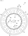
- an electric motor 10 includes a stator 20, a rotor 30, a case 50, and a rotation shaft 60.
- the stator 20 and the rotor 30 are accommodated in the case 50.
- the stator 20 is fixed to the case 50.
- the electric motor 10 an inner rotor type electric motor in which the rotor 30 is located inside the stator 20 is adopted.
- an outer rotor type electric motor in which the rotor 30 is located outside the stator 20 may be adopted.
- the electric motor 10 is a 12-pole 18-slot three-phase AC motor.
- the number of poles, the number of slots, the number of phases, and the like can be changed as appropriate.
- the stator 20 includes a stator core 21 and a winding (not shown).
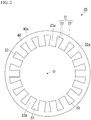
- the stator core 21 includes an annular core back part 22 and a plurality of tooth parts 23.
- an axial direction (a direction of a central axis O of the stator core 21) of the stator core 21 (the core back part 22) is referred to as an axial direction
- a radial direction (a direction orthogonal to the central axis O of the stator core 21) of the stator core 21 (the core back part 22) is referred to as a radial direction
- a circumferential direction (a direction of rotation around the central axis O of the stator core 21) of the stator core 21 (the core back part 22) is referred to as a circumferential direction.
- the core back part 22 is formed in an annular shape in a plan view of the stator 20 when seen in the axial direction.
- the plurality of tooth parts 23 protrude from the core back part 22 inward in the radial direction (toward the central axis O of the core back part 22 in the radial direction).
- the plurality of tooth parts 23 are disposed at equal intervals in the circumferential direction.
- 18 tooth parts 23 are provided at an interval of 20 degrees of a central angle centered on the central axis O.
- the plurality of tooth parts 23 are formed to have the same shape and the same size as each other.
- the winding is wound around the tooth part 23.
- the winding may be a concentrated winding or a distributed winding.
- the rotor 30 is disposed inside the stator 20 (the stator core 21) in the radial direction.
- the rotor 30 includes a rotor core 31 and a plurality of permanent magnets 32.
- the rotor core 31 is formed in an annular shape (an annular ring) disposed coaxially with the stator 20.
- the rotation shaft 60 is disposed in the rotor core 31.
- the rotation shaft 60 is fixed to the rotor core 31.
- the plurality of permanent magnets 32 are fixed to the rotor core 31.
- a set of two permanent magnets 32 forms one magnetic pole.
- the plurality of sets of permanent magnets 32 are disposed at equal intervals in the circumferential direction.
- 12 sets of (24 in total) permanent magnets 32 are provided at an interval of 30 degrees of the central angle centered on the central axis O.
- an interior permanent magnet motor is adopted as a permanent magnetic electric motor.
- a plurality of through-holes 33 which pass through the rotor core 31 in the axial direction are formed in the rotor core 31.
- the plurality of through-holes 33 are provided corresponding to the plurality of permanent magnets 32.
- Each of the permanent magnets 32 is fixed to the rotor core 31 in a state in which it is disposed in the corresponding through-hole 33.
- Each of the permanent magnets 32 is fixed to the rotor core 31, for example, by adhering an outer surface of the permanent magnet 32 and an inner surface of the through-hole 33 with an adhesive or the like.
- a surface permanent magnet motor may be adopted instead of an interior permanent magnet motor.
- Both the stator core 21 and the rotor core 31 are laminated cores.
- the laminated core is formed by stacking a plurality of electrical steel sheets 40.
- a stacking thickness of each of the stator core 21 and the rotor core 31 is, for example, 50.0 mm.
- An outer diameter of the stator core 21 is, for example, 250.0 mm.
- An inner diameter of the stator core 21 is, for example, 165.0 mm.
- An outer diameter of the rotor core 31 is, for example, 163.0 mm.
- An inner diameter of the rotor core 31 is, for example, 30.0 mm.
- these values are examples, and the stacking thickness, the outer diameter and the inner diameter of the stator core 21, and the stacking thickness, the outer diameter and the inner diameter of the rotor core 31 are not limited to these values.
- the inner diameter of the stator core 21 is based on a tip end portion of the tooth part 23 of the stator core 21.
- the inner diameter of the stator core 21 is a diameter of a virtual circle inscribed in the tip end portions of all the tooth parts 23.
- Each of the electrical steel sheets 40 forming the stator core 21 and the rotor core 31 is formed, for example, by punching an electrical steel sheet as a base material.
- the electrical steel sheet 40 a known electrical steel sheet can be used.
- a chemical composition of the electrical steel sheet 40 is not particularly limited.
- a non-grain-oriented electrical steel sheet is adopted as the electrical steel sheet 40.
- a non-grain-oriented electrical steel sheet for example, a non-grain-oriented electrical steel strip of JIS C 2552:2014 can be adopted.
- the electrical steel sheet 40 it is also possible to adopt a grain-oriented electrical steel sheet instead of the non-grain-oriented electrical steel sheet.
- a grain-oriented electrical steel sheet for example, a grain-oriented electrical steel strip of JIS C 2553:2012 can be adopted.
- Insulation coatings are provided on both surfaces of the electrical steel sheet 40 in order to improve workability of the electrical steel sheet and iron loss of the laminated core.
- an inorganic compound, (2) an organic resin, (3) a mixture of an inorganic compound and an organic resin, and the like can be applied as a substance constituting the insulation coating.
- the inorganic compound include (1) a complex of dichromate and boric acid, (2) a complex of phosphate and silica, and the like.
- the organic resin include an epoxy-based resin, an acrylic-based resin, an acrylic-styrene-based resin, a polyester-based resin, a silicone-based resin, a fluorine-based resin, and the like.
- a thickness of the insulation coating (a thickness per one surface of the electrical steel sheet 40) is preferably 0.1 ⁇ m or more.
- the thickness of the insulation coating (the thickness per one surface of the electrical steel sheet 40) is preferably 0.1 ⁇ m or more and 5 ⁇ m or less.
- the thickness of the insulation coating is more preferably 0.1 ⁇ m or more and 2 ⁇ m or less.
- the thickness of the electrical steel sheet 40 is preferably 0.10 mm or more in consideration of the effect of improving the iron loss and the manufacturing cost.
- the thickness of the electrical steel sheet 40 is preferably 0.65 mm or less.
- the thickness of the electrical steel sheet 40 is preferably 0.35 mm or less.
- the thickness of the electrical steel sheet 40 is more preferably 0.20 mm or 0.25 mm.
- the thickness of each of the electrical steel sheets 40 is, for example, 0.10 mm or more and 0.65 mm or less.
- the thickness of each of the electrical steel sheets 40 is preferably 0.10 mm or more and 0.35 mm or less, and more preferably 0.20 mm or 0.25 mm.
- the thickness of the electrical steel sheet 40 includes the thickness of the insulation coating.
- the plurality of electrical steel sheets 40 forming the stator core 21 are stacked in a thickness direction.
- the thickness direction is a thickness direction of the electrical steel sheet 40.
- the thickness direction corresponds to the stacking direction of the electrical steel sheets 40.
- the tooth part 23 is not shown.
- the plurality of electrical steel sheets 40 are disposed coaxially with respect to the central axis O.
- the electrical steel sheet 40 includes a core back part 22 and a plurality of tooth parts 23.
- an adhesion part 41 for adhering the electrical steel sheets 40 is disposed between the electrical steel sheets 40 adjacent to each other in the stacking direction.
- the adhesion part 41 partially adheres the electrical steel sheets 40 adjacent to each other in the stacking direction.
- the adhesion parts 41 adjacent to each other in the stacking direction have different arrangement regions in a plan view seen in the stacking direction.
- a range in which the adhesion parts 41 adjacent to each other in the stacking direction are disposed so that arrangement regions thereof are different from each other in a plan view seen in the stacking direction (hereinafter, referred to as an arrangement range in which the arrangement regions are different from each other) may be the entire stator core 21 and may be a part of the stator core 21.
- the arrangement range in which the arrangement regions are different from each other may be in one of the plurality of tooth parts 23 arranged in the circumferential direction.
- the arrangement range in which the arrangement regions are different from each other may be in one of layers formed by the plurality of adhesion parts 41, which will be described later, arranged in the stacking direction.
- the arrangement region is a region on a surface (a first surface) 40a of the electrical steel sheet 40 on which the adhesion part 41 is disposed. That is, the arrangement region is an adhesion region on the surface 40a of the electrical steel sheet 40 on which the adhesion part 41 is provided.
- the adhesion region in which the adhesion part 41 is provided and a non-adhesion region in which the adhesion part 41 is not provided are formed on the surface 40a of the electrical steel sheet 40.
- the adhesion region of the electrical steel sheet 40 in which the adhesion part 41 is provided means a region of the first surface 40a of the electrical steel sheet 40 in which the adhesive cured without being divided is provided.
- non-adhesion region of the electrical steel sheet 40 in which the adhesion part 41 is not provided means a region on the first surface 40a of the electrical steel sheet 40 in which the adhesive cured without being divided is not provided.
- an adhesive which is cured without being divided between the electrical steel sheets 40 adjacent to each other in the stacking direction is referred to as one adhesion part 41.
- a stacking surface of the core back part 22 is referred to as a surface 22a.
- a stacking surface of the tooth part 23 is referred to as a surface 23a.
- the adhesion part 41 is preferably provided on at least one of the surface 22a of the core back part 22 and the surface 23a of the tooth part 23 in the electrical steel sheet 40. That is, the adhesion part 41 may be provided only on the surface 22a of the core back part 22 in the electrical steel sheet 40. The adhesion part 41 may be provided only on the surface 23a of the tooth part 23 in the electrical steel sheet 40. The adhesion part 41 may be provided on both the surface 22a of the core back part 22 and the surface 23a of the tooth part 23 in the electrical steel sheet 40.
- one or a plurality of adhesion parts 41 may form a layer (hereinafter, also referred to as a layer formed by the adhesion parts 41) between the two electrical steel sheets 40.
- the layer formed by the adhesion part 41 includes one or the plurality of adhesion parts 41.
- a plurality of layers formed by the adhesion part 41 are provided in the stacking direction.
- the adhesion part 41 is provided so that the arrangement regions overlap at an N-layer interval (N is a natural number) in a plan view seen in the stacking direction.
- the N-layer interval means an N-layer interval in the layers by the adhesion part 41.
- each of the adhesion parts 41 is disposed at the same position in the electrical steel sheet 40 at the N-layer interval (N is a natural number) in the layers formed by the adhesion part 41.
- the arrangement regions of the adhesion part 41 overlap at the N-layer interval over the entire length of the stator core 21 in the stacking direction.
- the fact that the arrangement regions of the adhesion part 41 overlap at the N-layer interval in the plan view seen in the stacking direction means that the arrangement regions of the adhesion part 41 overlap at the N-layer interval in the plan view seen in the stacking direction at least some of the layers formed by the plurality of adhesion parts 41 arranged in the stacking direction in one of the plurality of tooth parts 23 arranged in the circumferential direction.
- the adhesion part 41 is provided only on the surface 23a of the tooth part 23 .
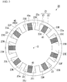
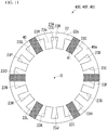
- the plurality of tooth parts 23 included in each of the electrical steel sheets 40 are also referred to as tooth parts 23A to 23R in the clockwise order as shown in FIGS. 4 and 5 .
- the plurality of electrical steel sheets 40 included in the stator core 21 are also referred to as electrical steel sheets 400, 40A, 40B, ... in the order from the first side in the stacking direction to the second side opposite to the first side in the stacking direction (refer to FIG. 8 ).
- the adhesion parts 41 are disposed at positions adjacent to the first side in the stacking direction with respect to the electrical steel sheets 40A, 40B, ....
- the adhesion part 41 is not disposed at a position adjacent to the first side in the stacking direction with respect to the electrical steel sheet 400.
- the adhesion part 41 is disposed at a position adjacent to the second side in the stacking direction with respect to the electrical steel sheet 400.
- the adhesion part 41 disposed (provided) on the electrical steel sheet 40 means the adhesion part 41 disposed at a position adjacent to the first side in the stacking direction with respect to the electrical steel sheet 40.
- the tooth parts 23A of the electrical steel sheets 40 overlap each other in a plan view seen in the stacking direction. The same applies to the tooth parts 23B to 23R of each of the electrical steel sheets 40.
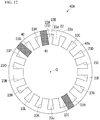
- the adhesion part 41 is provided on the surface 23a of each of the tooth parts 23A, 23C, 23E, 23G, 23I, 23K, 23M, 23O, and 23Q. Further, as shown in FIG. 5 , in the electrical steel sheet 40B adjacent to the electrical steel sheet 40A in the stacking direction, the adhesion part 41 is provided on the surface 23a of each of the tooth parts 23B, 23D, 23F, 23H, 23J, 23L, 23N, 23P, and 23R. Each of the adhesion parts 41 is formed in a strip shape in a plan view and is disposed along an exterior of the tooth part 23.
- 18 tooth parts 23 are provided at an interval of 20 degrees of a central angle centered on the central axis O.
- each of the adhesion parts 41 extends from the surface 23a of each of the tooth parts 23A, 23C, 23E, 23G, 231, 23K, 23M, 23O, and 23Q to an outer peripheral edge of the core back part 22 in the radial direction along the tooth parts 23.
- each of the adhesion parts 41 extends from the surface 23a of each of the tooth parts 23B, 23D, 23F, 23H, 23J, 23L, 23N, 23P, and 23R to an outer peripheral edge of the core back part 22 in the radial direction along the tooth parts 23.
- stator core 21 of this example 11 electrical steel sheets 40 (400 to 40J) are stacked.
- stator core 21 including 11 electrical steel sheets 40 will be described as an example.
- the stator core 21 may include 12 or more electrical steel sheets 40.
- the adhesion parts 41 are provided so that the arrangement regions overlap at a one-layer interval in the plan view seen in the stacking direction.
- a portion marked with ⁇ indicates an outer portion (hereinafter, referred to as a core back outer part of the tooth part 23) of the tooth part 23 in the radial direction in (1) the tooth part 23 on which the adhesion part 41 is disposed and (2) the core back part 22 on which the adhesion part 41 is disposed.
- the tooth part 23 and the core back outer part of the tooth part 23 will also be referred to as the tooth part 23 and the like.
- the adhesion part 41 may be disposed only on one of the tooth part 23 and the core back outer part of the tooth part 23.
- the stator core 21 of this example includes the electrical steel sheet 400. However, as will be described later, since the adhesion part 41 is not disposed on the electrical steel sheet 400, the electrical steel sheet 400 is not shown in Table 1. Also in Tables 2 to 5 which will be described later, the electrical steel sheet 400 is not shown in each of the tables.
- ⁇ is shown in the column of the tooth part 23A of the electrical steel sheet 40A.
- This description means that the adhesion part 41 is disposed at a position adjacent to the first side in the stacking direction with respect to the tooth part 23A of the electrical steel sheet 40A.
- This description further means that the adhesion part 41 is disposed at a position adjacent to the first side in the stacking direction with respect to the core back outer part of the tooth part 23A of the electrical steel sheet 40A.
- the layer formed by the adhesion part 41 disposed on the first side in the stacking direction with respect to the electrical steel sheet 40A is referred to as a layer formed by the adhesion part 41 corresponding to the electrical steel sheet 40A. The same is applied to the electrical steel sheets 40B to 40J.
- ⁇ is not described in the column of the tooth part 23A of the electrical steel sheet 40B.
- This description means that the adhesion part 41 is not disposed at a position adjacent to the first side in the stacking direction with respect to the tooth part 23A of the electrical steel sheet 40B.
- This description further means that the adhesion part 41 is not disposed at a position adjacent to the first side in the stacking direction with respect to the core back outer part of the tooth part 23A of the electrical steel sheet 40B.
- the adhesion part 41 is provided on the surface 23a of each of the tooth parts 23 of a first group which will be described later and the surface 22a of a radial outer portion of each of the tooth parts 23 of the first group in the core back part 22.
- the tooth parts 23 of the first group referred to here mean the tooth parts 23A, 23C, 23E, 23G, 231, 23K, 23M, 23O, and 23Q.
- the adhesion part 41 is provided on the surface 23a of each of the tooth parts 23 of a second group which will be described later and the surface 22a of a radial outer portion of each of the tooth parts 23 of the second group in the core back part 22.
- the tooth parts 23 of the second group referred to here mean the tooth parts 23B, 23D, 23F, 23H, 23J, 23L, 23N, 23P, and 23R.
- two types of layers formed by adhesion parts 41 having different shapes in a plan view are provided in the stator core 21.
- the layers formed by two types of adhesion parts 41 correspond to the tooth parts 23 of the first group and the tooth parts 23 of the second group.
- the layers formed by the adhesion parts 41 having different shapes in the plan view are referred to as a layer formed by a first type of adhesion part 41 and a layer formed by a second type of adhesion part 41.
- the adhesion parts 41 are disposed on the tooth parts 23 and the like at an interval of one tooth part 23 in the circumferential direction.
- the adhesion part 41 when the adhesion part 41 is disposed on the tooth part 23A and the like in the layer formed by the first type of adhesion part 41, the adhesion part 41 is not disposed on the tooth part 23A and the like in the layer formed by the second type of adhesion part 41.
- the adhesion part 41 when the adhesion part 41 is not disposed on the tooth part 23A and the like in the layer formed by the first type of adhesion part 41, the adhesion part 41 is disposed on the tooth part 23A and the like of the layer formed by the second type of adhesion part 41. The same is applied to the tooth parts 23B to 23R.
- the layers formed by the two types of adhesion parts 41 are alternately disposed in the stacking direction.
- shapes of the layers formed by the adhesion part 41 in the plan view are the same at a one-layer interval.
- the stator core 21 is configured as follows. That is, another electrical steel sheet 40A is stacked next to the electrical steel sheet 40J (at a position adjacent to the second side in the stacking direction with respect to the electrical steel sheet 40J).
- the other electrical steel sheets 40B to 40J are stacked in this order at positions adjacent to the second side in the stacking direction with respect to the other electrical steel sheet 40A.
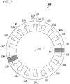
- the adhesion part 41 is provided so that the arrangement regions overlap at a two-layer interval in a plan view seen in the stacking direction.
- a portion marked with ⁇ indicates the tooth part 23 on which the adhesion part 41 is disposed and the outer portion of the tooth part 23 in the radial direction in the core back part 22 (the tooth part 23 and the like).
- the adhesion part 41 is provided on the surface 23a of each of the tooth parts 23 of a sixth group which will be described later, and the surface 22a of the radial outer portion of each of the tooth part 23 of the sixth group in the core back part 22.
- the tooth parts 23 of the sixth group referred to here mean the tooth parts 23A, 23D, 23G, 23J, 23M, and 23P.
- the adhesion part 41 is provided on the surface 23a of each of the tooth parts 23 of a seventh group which will be described later, and the surface 22a of the radial outer portion of each of the tooth part 23 of the seventh group in the core back part 22.
- the tooth parts 23 of the seventh group referred to here mean the tooth parts 23B, 23E, 23H, 23K, 23N, and 23Q.
- the adhesion part 41 is provided on the surface 23a of each of the tooth parts 23 of an eighth group which will be described later, and the surface 22a of the radial outer portion of each of the tooth part 23 of the eighth group in the core back part 22.
- the tooth parts 23 of the eighth group referred to here mean the tooth parts 23C, 23F, 231, 23L, 23O, and 23R.
- three types of layers formed by adhesion parts 41 having different shapes in a plan view are provided in the stator core 21.
- the layers formed by three types of adhesion parts 41 corresponds to the tooth parts 23 of the sixth group, the tooth parts 23 of the seventh group, and the tooth parts 23 of the eighth group.
- the adhesion parts 41 are disposed on the tooth parts 23 and the like at an interval of two tooth parts 23 in the circumferential direction.
- the layers formed by the adhesion parts 41 having different shapes in the plan view are referred to as a layer formed by a first type of adhesion part 41, a layer formed by a second type adhesion part 41, and a layer formed by a second type of adhesion part 41.
- the tooth part 23 and the like on which the adhesion part 41 is disposed in the layer formed by the second type of adhesion part 41 are shifted to the first side by one tooth part 23 and the like in the circumferential direction with respect to the tooth part 23 and the like on which the adhesion part 41 is disposed in the layer formed by the first type of adhesion part 41.
- the tooth part 23 and the like on which the adhesion part 41 is disposed in the layer formed by the third type of adhesion part 41 are shifted to the first side by one tooth part 23 and the like in the circumferential direction with respect to the tooth part 23 and the like on which the adhesion part 41 is disposed in the layer formed by the second type of adhesion part 41.
- the layer by the first type of adhesion part 41, the layer by the second type of adhesion part 41, and the layer by the third type of adhesion part 41 are disposed in order from the first side to the second side in the stacking direction.
- the shapes of the layers formed by the adhesion part 41 in the plan view are the same at a two-layer interval.
- stator core 21 When 12 or more electrical steel sheets 40 are stacked in the stator core 21, the stator core 21 is configured as follows. That is, another electrical steel sheet 40A is stacked next to the electrical steel sheet 40J. Hereinafter, the other electrical steel sheets 40B to 40J are stacked in this order at positions adjacent to the second side in the stacking direction with respect to the other electrical steel sheet 40A.
- the other electrical steel sheet 40A when another electrical steel sheet 40A is stacked next to the electrical steel sheet 40J, the other electrical steel sheet 40A is disposed in a state in which it rotates around the central axis O with respect to the electrical steel sheet 40J so that the tooth part 23C of the other electrical steel sheet 40A overlaps the tooth part 23A of the electrical steel sheet 40J.
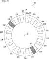
- the adhesion parts 41 are provided so that the arrangement regions overlap at a seven-layer interval in a plan view seen in the stacking direction.
- a portion marked with ⁇ indicates the tooth part 23 on which the adhesion part 41 is disposed and the outer portion of the tooth part 23 in the radial direction in the core back part 22 on which the adhesion part 41 is disposed (the tooth part 23 and the like).
- the adhesion part 41 is provided on the surface 23a of each of the tooth parts 23 of an eleventh group which will be described later and the surface 22a of the radial outer portion of each of the tooth parts 23 of the eleventh group in the core back part 22.
- the tooth parts 23 of the eleventh group referred to here mean the tooth parts 23A, 231, and 23Q.
- the adhesion part 41 is provided on the surface 23a of each of the tooth parts 23 of a twelfth group which will be described later and the surface 22a of the radial outer portion of each of the tooth parts 23 of the twelfth group in the core back part 22.
- the tooth parts 23 of the eleventh group referred to here mean the tooth parts 23B, 23J, and 23R.
- the adhesion part 41 is provided on the surface 23a of each of the tooth parts 23 of a thirteenth group which will be described later and the surface 22a of the radial outer portion of each of the tooth parts 23 of the thirteenth group in the core back part 22.
- the tooth parts 23 of the thirteenth group referred to here mean the tooth parts 23C and 23K.
- the adhesion part 41 is provided on the surface 23a of each of the tooth parts 23 of a fourteenth group which will be described later and the surface 22a of the radial outer portion of each of the tooth parts 23 of the fourteenth group in the core back part 22.
- the tooth parts 23 of the fourteenth group referred to here mean the tooth parts 23D and 23L.
- the adhesion part 41 is provided on the surface 23a of each of the tooth parts 23 of a fifteenth group which will be described later and the surface 22a of the radial outer portion of each of the tooth parts 23 of the fifteenth group in the core back part 22.
- the tooth parts 23 of the fifteenth group referred to here mean the tooth parts 23E and 23M.
- the adhesion part 41 is provided on the surface 23a of each of the tooth parts 23 of a sixteenth group which will be described later and the surface 22a of the radial outer portion of each of the tooth parts 23 of the sixteenth group in the core back part 22.
- the tooth parts 23 of the sixteenth group referred to here mean the tooth parts 23F and 23N.
- the adhesion part 41 is provided on the surface 23a of each of the tooth parts 23 of a seventeenth group which will be described later and the surface 22a of the radial outer portion of each of the tooth parts 23 of the seventeenth group in the core back part 22.
- the tooth parts 23 of the seventeenth group referred to here mean the tooth parts 23G and 23O.
- the adhesion part 41 is provided on the surface 23a of each of the tooth parts 23 of an eighteenth group which will be described later and the surface 22a of the radial outer portion of each of the tooth parts 23 of the eighteenth group in the core back part 22.
- the tooth parts 23 of the eighteenth group referred to here mean the tooth parts 23H and 23P.
- the adhesion part 41 is provided on the surface 23a of each of the tooth parts 23 of a nineteenth group which will be described later and the surface 22a of the radial outer portion of each of the tooth parts 23 of the nineteenth group in the core back part 22.
- the tooth parts 23 of the nineteenth group referred to here mean the tooth parts 231 and 23Q.
- the adhesion part 41 is provided on the surface 23a of each of the tooth parts 23 of a twentieth group which will be described later and the surface 22a of the radial outer portion of each of the tooth parts 23 of the twentieth group in the core back part 22.
- the tooth parts 23 of the twentieth group referred to here mean the tooth parts 23J and 23R.
- 10 types of layers formed by the adhesion parts 41 having different shapes in a plan view are provided in the stator core 21.
- the layers formed by the 10 types of adhesion parts 41 correspond from the tooth parts 23 of the eleventh group to the tooth parts 23 of the twentieth group.
- the adhesion parts 41 are disposed on the tooth parts 23 and the like at intervals of one, seven, or nine tooth parts 23 in the circumferential direction.
- stator core 21 When 12 or more electrical steel sheets 40 are stacked in the stator core 21, the stator core 21 is configured as follows. That is, another electrical steel sheet 40A is stacked next to the electrical steel sheet 40J. Hereinafter, other electrical steel sheets 40B to 40J are stacked in this order at positions adjacent to the second side in the stacking direction with respect to the other electrical steel sheet 40A.
- the adhesion parts 41 are disposed at the following two locations. Specifically, the adhesion parts 41 are respectively disposed on the tooth part 23A and the like of the electrical steel sheet 401 and the tooth part 23B and the like of the electrical steel sheet 40J.
- stator core 21 shown in the above-described examples of Tables 1 and 2 has the following first and second configurations relating to the adhesion part 41.
- First configuration a configuration in which the adhesion parts 41 are disposed at equal intervals in the stacking direction (at intervals of the equal number of layers in the stacking direction) over the entire length of the stator core 21 in the stacking direction in one of the plurality of tooth parts 23 arranged in the circumferential direction.
- Second configuration a configuration in which the adhesion parts 41 are disposed at equal intervals in the circumferential direction (at intervals of the equal number of tooth parts 23 in the circumferential direction) over the entire circumference of the stator core 21 in one of the layers formed by the plurality of adhesion parts 41 arranged in the stacking direction.
- stator core 21 when the number of electrical steel sheets 40 included in the stator core 21 is larger (for example, when 21 electrical steel sheets 40 are provided), the stator core 21 may have the first configuration. In this case, the electrical steel sheets 40 after the twelfth electrical steel sheet 40 are stacked as described above.
- the first interval is an interval set for each of the tooth parts 23A to 23R of the electrical steel sheet 40.
- the second interval is an interval set for each of the layers by each of the adhesion parts 41.
- the first interval is an interval indicating by how many layers the adhesion parts 41 in which the arrangement regions thereof overlap each other when seen in the stacking direction are separated from each other in a target tooth parts 23.
- Table 1 attention is paid to the tooth part 23A.
- the adhesion parts 41 in which the arrangement regions thereof overlap each other when seen in the stacking direction are disposed at a one-layer interval over the entire length of the stator core 21 in the stacking direction.
- the first interval is 1 over the entire length of the stator core 21 in the stacking direction.
- the second interval is an interval indicating how many tooth parts 23 on which the adhesion part 41 is not disposed are disposed between the circumferential directions of the other adhesion parts 41 adjacent to each other in the circumferential direction in the layer formed by one target adhesion part 41.
- Table 1 attention is paid to the layer formed by the adhesion part 41 corresponding to the electrical steel sheet 40A.
- one tooth part 23 is disposed between the circumferential directions of the other adhesion parts 41 adjacent to each other in the circumferential direction over the entire circumference of the stator core 21.
- the second interval is 1 over the entire circumference of the stator core 21.
- the first configuration and the second configuration can be expressed using the first interval and the second interval as follows.
- First configuration a configuration in which the first intervals are equal to each other over the entire length of the stator core 21 in the stacking direction in one of the plurality of tooth parts 23 arranged in the circumferential direction.
- Second configuration a configuration in which the second intervals are equal to each other over the entire circumference of the stator core 21 in one of the layers formed by the plurality of adhesion parts 41 arranged in the stacking direction.
- the first interval is 1 over the entire length of the stator core 21 in the stacking direction.
- the second interval is 1 over the entire circumference of the stator core 21.
- the stator core 21 includes the first configuration and the second configuration.
- the first interval is 2 over the entire length of the stator core 21 in the stacking direction.
- the second interval is 2 over the entire circumference of the stator core 21.
- the stator core 21 includes the first configuration and the second configuration.
- the first interval is 7 in the tooth parts 231, 23J, 23Q, and 23R.
- the tooth parts 23 do not have the first configuration because there is only one first interval.
- the first interval for the tooth parts 23A to 23H and 23K to 23P is not specified because there is no other adhesion parts 41 in which the arrangement regions thereof overlap each other when seen in the stacking direction. Since the first interval is not defined for these tooth parts 23, the first configuration is not provided.
- the second intervals in the layers by the adhesion parts 41 corresponding to the electrical steel sheets 40A and 40B are 7, 7, and 1.
- the second intervals in the layers by the adhesion parts 41 corresponding to the electrical steel sheets 40C to 40J are 7 and 9.
- all the layers formed by the plurality of adhesion parts 41 do not have the second configuration.
- the stator core 21 when the number of electrical steel sheets 40 included in the stator core 21 is larger, the stator core 21 may have the first configuration.
- stator core 21 of the example shown in Table 4 does not have the first configuration and the second configuration.
- stator core 21 may not have the first configuration and the second configuration as in the example of stator cores 21 shown in Tables 3 and 4.
- the stator core 21 may not have one of the first configuration and the second configuration and may not have both of them.
- stator core 21 which does not have the first configuration and the second configuration will be described with reference to Tables 5 and 6.
- stator core 21 having the first configuration
- the following third configuration or fifth configuration may be provided.
- Third configuration a configuration in which the arrangement regions of the adhesion parts 41 overlap each other at an interval of different prime number layers in a plan view seen in the stacking direction in a part of the region of the stator core 21 in the stacking direction in one of the plurality of tooth parts 23 arranged in the circumferential direction.
- the third configuration is a configuration in which the first intervals adjacent to each other in the stacking direction are prime numbers different from each other in a part of the region of the stator core 21 in the stacking direction in one of the plurality of tooth parts 23 arranged in the circumferential direction.
- Fifth configuration a configuration in which the arrangement regions of the adhesion parts 41 overlap each other at an interval of different prime number layers over the entire length of the stator core 21 in the stacking direction, in a plan view in the stacking direction, in one of the plurality of tooth parts 23 arranged in the circumferential direction.
- the fifth configuration is a configuration in which the first intervals adjacent to each other in the stacking direction are prime numbers different from each other over the entire length of the stator core 21 in the stacking direction in one of the plurality of tooth parts 23 arranged in the circumferential direction.
- stator core 21 having the second configuration
- following fourth configuration or sixth configuration may be provided.
- Fourth configuration a configuration in which the number of tooth parts 23 between the adhesion parts 41 adjacent to each other in the circumferential direction is a prime number different from each other in a part of the region of the stator core 21 in the circumferential direction in one of the layers formed by the plurality of adhesion parts 41 arranged in the stacking direction.
- the fourth configuration is a configuration in which the second intervals adjacent to each other in the circumferential direction are prime numbers different from each other in a part of the region of the stator core 21 in the circumferential direction in one of the layers formed by the plurality of adhesion parts 41 arranged in the stacking direction.
- Sixth configuration a configuration in which the number of tooth parts 23 between the adhesion parts 41 adjacent to each other in the circumferential direction is a prime number different from each other over the entire circumference of the stator core 21 in one of the layers formed by the plurality of adhesion parts 41 arranged in the stacking direction.
- the sixth configuration is a configuration in which the second intervals adjacent to each other in the circumferential direction are prime numbers different from each other over the entire circumference of the stator core 21 in one of the layers formed by the plurality of adhesion parts 41 arranged in the stacking direction.
- stator core 21 for each of cases will be described while attention is paid to the above configuration.
- stator core 21 shown in an example of Table 5 will be described.
- each of the tooth parts 23 on which the adhesion part 41 is disposed is shifted to the first side in the circumferential direction by one tooth part with respect to the layers adjacent to the first side in the stacking direction.
- each of the tooth parts 23 on which the adhesion part 41 is disposed is shifted to the first side in the circumferential direction by one tooth part with respect to the layers adjacent to the first side in the stacking direction. Further, in each of the layers of the adhesion parts 41 corresponding to the electrical steel sheets 40E and 40F, the number of the adhesion parts 41 disposed is reduced to three. Specifically, in the layer formed by the adhesion part 41 corresponding to the electrical steel sheet 40E, when the adhesion part 41 tries to shift from the tooth part 23R to the first side in the circumferential direction, the adhesion part 41 is not shifted to the tooth part 23A but disappears.
- each of the tooth parts 23 on which the adhesion part 41 is disposed is shifted to the first side in the circumferential direction by one tooth part with respect to the layers adjacent to the first side in the stacking direction. Further, in each of the layers of the adhesion parts 41 corresponding to the electrical steel sheets 40G and 40H, the number of the adhesion parts 41 is increased to four. Specifically, in the layer formed by the adhesion part 41 corresponding to the electrical steel sheet 40G, the adhesion part 41 is disposed on the tooth part 23A.
- each of the tooth parts 23 on which the adhesion part 41 is disposed is shifted to the first side in the circumferential direction by one tooth part with respect to the layers adjacent to the first side in the stacking direction. Further, in each of the layers of the adhesion parts 41 corresponding to the electrical steel sheets 401 and 40J, the number of the adhesion parts 41 disposed is reduced to three again. Specifically, in the layer formed by the adhesion part 41 corresponding to the electrical steel sheet 401, when the adhesion part 41 tries to shift from the tooth part 23R to the first side in the circumferential direction, the adhesion part 41 is not shifted to the tooth part 23A but disappears.
- the second intervals are arranged in the order of 3, 5, 3, and 3 toward the first side in the circumferential direction.
- the second intervals are arranged in the order of 3, 5, and 7 toward the first side in the circumferential direction. These layers have the sixth configuration.
- the stator core 21 of Case 1 does not have the third configuration and the fifth configuration.
- each of the tooth parts 23 on which the adhesion part 41 is disposed is shifted to the first side in the circumferential direction by one tooth part with respect to the layers adjacent to the first side in the stacking direction.
- each of the tooth parts 23 on which the adhesion part 41 is disposed is shifted to the first side in the circumferential direction by one tooth part with respect to the layers adjacent to the first side in the stacking direction. Further, in each of the layers of the adhesion parts 41 corresponding to the electrical steel sheets 40D to 401, the number of the adhesion parts 41 disposed is reduced to three.
- the adhesion part 41 when the adhesion part 41 tries to shift from the tooth parts 23F, 23L, and 23R to the first side in the circumferential direction, the adhesion part 41 is not shifted to the tooth parts 23G, 23M, and 23A but disappears.
- the tooth part 23 on which the adhesion part 41 is disposed is shifted to the first side in the circumferential direction by one tooth part with respect to the layers adjacent to the first side in the stacking direction. Further, the number of the adhesion parts 41 is increased to 6 in each of the layers formed by the adhesion parts 41 corresponding to the electrical steel sheet 40J. Specifically, in the layer formed by the adhesion parts 41 corresponding to the electrical steel sheet 40J, the adhesion parts 41 are disposed on the tooth parts 23A, 23G, and 23M.
- such a stator core 21 has the fifth configuration in some of the tooth parts 23 among the plurality of tooth parts 23 arranged in the circumferential direction.
- the tooth parts 23A, 23D, 23G, 23J, 23M, and 23P in which the three arrangement regions thereof overlap each other in a plan view seen in the stacking direction will be described.
- the first intervals adjacent to each other in the stacking direction are disposed in the order of 5 and 2 from the first side to the second side in the stacking direction over the entire length of the stator core 21 in the stacking direction.
- the first intervals adjacent to each other in the stacking direction are disposed in the order of 2 and 5 from the first side to the second side in the stacking direction over the entire length of the stator core 21 in the stacking direction.
- the tooth parts 23A, 23D, 23G, 23J, 23M, and 23P have the fifth configuration.
- the stator core 21 of Case 2 does not have the third configuration, the fourth configuration, and the sixth configuration.
- the first intervals are 5 and 2 from the first side to the second side in the stacking direction.
- the first intervals may be 5, 2, 5, 2, ... from the first side to the second side in the stacking direction.
- the first intervals may be 5, 2, 2, 5, ... from the first side to the second side in the stacking direction. In this way, the first interval may be changed for each of the tooth parts 23.
- stator core 21 has the fifth configuration in all the tooth parts 23 arranged in the circumferential direction.
- the tooth parts 23A to 23C and 23J to 23L in which the three arrangement regions thereof overlap each other in a plan view seen in the stacking direction will be described.
- the first intervals adjacent to each other in the stacking direction are arranged in the order of 5 and 2 from the first side to the second side in the stacking direction over the entire length of the stator core 21 in the stacking direction.
- the tooth parts 23G to 231 and 23P to 23R in which the three arrangement regions thereof overlap each other in a plan view seen in the stacking direction will be described.
- the first intervals adjacent to each other in the stacking direction are arranged in the order of 2, 5 from the first side to the second side in the stacking direction over the entire length of the stator core 21 in the stacking direction.
- the tooth parts 23D to 23F and 23M to 23O in which the four arrangement regions thereof overlap each other in a plan view seen in the stacking direction will be described.
- the first intervals adjacent to each other in the stacking direction are arranged in the order of 2, 5 and 2 from the first side to the second side in the stacking direction over the entire length of the stator core 21 in the stacking direction.
- stator core 21 has the sixth configuration in all layers of the layer formed by the plurality of adhesion parts 41.
- the second intervals are arranged in the order of 2, 5, 2, and 5 toward the first side in the circumferential direction.
- the stator core 21 of Case 3 does not have the third configuration and the fourth configuration.
- a configuration of the stator core 21 in which the adhesion part 41 is disposed to have at least one of the third configuration and the fourth configuration is hereinafter referred to as a first unequal interval configuration.
- a configuration of the stator core 21 in which the adhesion part 41 is disposed to have one of the fifth configuration and the sixth configuration is hereinafter referred to as a second unequal interval configuration.
- a configuration of the stator core 21 in which the adhesion part 41 is disposed to have both the fifth configuration and the sixth configuration is hereinafter referred to as a third unequal interval configuration.
- the stator core 21 having the first unequal interval configuration, the second unequal interval configuration, or the third unequal interval configuration can further prevent resonance frequencies of the electric motor and the laminated core from matching.
- stator core 21 of Case 1 since some of the layers formed by the plurality of adhesion parts 41 have the fourth configuration, the stator core 21 of this example has the fourth configuration. Since the remaining layers of the layers formed by the plurality of adhesion parts 41 have the sixth configuration, the stator core of this example has the sixth configuration. The stator core 21 of Case 1 does not have the third configuration and the fifth configuration.
- stator core 21 of Case 1 has the first unequal interval configuration because it has the fourth configuration of the third configuration and the fourth configuration.
- the stator core 21 of Case 1 has only the sixth configuration of the fifth configuration and the sixth configuration. Therefore, the stator core 21 of this example has the second unequal interval configuration, but does not have the third unequal interval configuration.
- the stator core 21 of the case 2 has the fifth configuration.
- the stator core 21 of Case 2 does not have the third configuration, the fourth configuration, and the sixth configuration.
- stator core 21 of this example does not have the first unequal interval configuration because it does not have both the third configuration and the fourth configuration.
- the stator core 21 of this example has only the fifth configuration of the fifth configuration and the sixth configuration. Therefore, the stator core 21 of this example has the second unequal interval configuration, but does not have the third unequal interval configuration.
- the stator core 21 of Case 3 does not have the third configuration and the fourth configuration, but has the fifth configuration and the sixth configuration.
- stator core 21 of this example does not have the first unequal interval configuration and the second unequal interval configuration, but has the third unequal interval configuration.
- the effect of preventing the resonance frequencies of the electric motor and the laminated core (the stator core) from matching is greater in the second unequal interval configuration than in the first unequal interval configuration.
- the arrangement regions of the adhesion parts 41 overlap each other at an interval of different prime number layers over the entire length in the stacking direction, or the number of adhesion parts 41 is a prime number in which the numbers of tooth parts 23 between adhesion parts 41 adjacent to each other in the circumferential direction over the entire circumference are different from each other. Therefore, this is because the second unequal interval configuration improves the non-uniformity of the adhesion part of the laminated core as compared with the first unequal interval configuration.
- This effect is greater in the third unequal interval configuration than in the second unequal interval configuration.
- the arrangement regions of the adhesion parts 41 overlap each other at an interval of different prime number layers over the entire length in the stacking direction, and also the adhesion parts 41 are a prime number in which the number of tooth parts 23 between the adhesion parts 41 adjacent to each other in the circumferential direction over the entire circumference is different from each other. Therefore, this is because the third unequal interval configuration further improves the non-uniformity of the adhesion part of the laminated core as compared with the second unequal interval configuration.
- thermosetting adhesive by polymer bonding or the like is used.
- a composition of the adhesive (1) an acrylic-based resin, (2) an epoxy-based resin, (3) a composition containing an acrylic-based resin and an epoxy-based resin, and the like can be applied.
- a radical polymerization type adhesive or the like can also be used in addition to the thermosetting adhesive.
- a room temperature curing type (room temperature adhesive type) adhesive is desirable.
- the room temperature curing type adhesive cures at 20°C to 30°C.
- a numerical range represented by using "to” means a range including numerical values before and after "to” as the lower limit value and the upper limit value.
- an acrylic-based adhesive is preferable.
- Typical acrylic-based adhesives include a second generation acrylic-based adhesive (SGA) and the like.
- SGA second generation acrylic-based adhesive
- An anaerobic adhesive, an instant adhesive, and an elastomer-containing acrylic-based adhesive can be used as long as the effects of the present invention are not impaired.
- the adhesive referred to here refers to a state before curing.
- the adhesive becomes the adhesion part 41 when the adhesive is cured.
- An average tensile modulus of elasticity E of the adhesion part 41 at room temperature (20°C to 30°C) is in a range of 1500 MPa to 4500 MPa.
- a lower limit value of the average tensile modulus of elasticity E of the adhesion part 41 is 1500 MPa, and more preferably 1800 MPa.
- an upper limit value of the average tensile modulus of elasticity E of the adhesion part 41 is 4500 MPa, and more preferably 3650 MPa.
- the average tensile modulus of elasticity E is measured by a resonance method. Specifically, the tensile modulus of elasticity is measured based on JIS R 1602:1995.
- a sample for measurement (not shown) is produced.
- This sample is obtained by adhering two electrical steel sheets 40 with an adhesive to be measured and curing the adhesive to form the adhesion part 41.
- the adhesive is a thermosetting type
- the curing is performed by heating and pressurizing under heating and pressurizing conditions in an actual operation.
- the adhesive is a room temperature curing type
- it is performed by pressurizing at room temperature.
- the tensile modulus of elasticity of this sample is measured by the resonance method.
- a method for measuring the tensile modulus of elasticity by the resonance method is performed based on JIS R 1602: 1995.
- the tensile modulus of elasticity of the adhesion part 41 alone can be obtained by removing an influence of the electrical steel sheet 40 itself from the tensile modulus of elasticity (a measured value) of the sample by calculation.
- the tensile modulus of elasticity obtained from the sample in this way is equal to an average value of all the stator cores 21 which are the laminated cores. Thus, this value is regarded as the average tensile modulus of elasticity E.
- the composition is set so that the average tensile modulus of elasticity E hardly changes at a stacking position in the stacking direction or at a circumferential position around the central axis of the stator core 21. Therefore, the average tensile modulus of elasticity E can be set to a value obtained by measuring the cured adhesion part 41 at an upper end position of the stator core 21.
- thermosetting adhesive for example, a method in which an adhesive is applied to the electrical steel sheet 40 and then adhered by one of heating and press-stacking, or both of them can be adopted.
- a heating unit may be, for example, one of heating in a high temperature bath or an electric furnace, a method of directly energizing, and the like, and may be any one.
- the thickness of the adhesion part 41 is preferably 1 ⁇ m or more.
- the thickness of the adhesion part 41 exceeds 100 ⁇ m, an adhesion force is saturated. Further, as the adhesion part 41 becomes thicker, the space factor decreases, and the magnetic properties such as iron loss of the laminated core decrease. Therefore, the thickness of the adhesion part 41 is 1 ⁇ m or more and 100 ⁇ m or less. The thickness of the adhesion part 41 is more preferably 1 ⁇ m or more and 10 ⁇ m or less.
- the thickness of the adhesion part 41 means an average thickness of the adhesion part 41.
- the average thickness of the adhesion part 41 is more preferably 1.0 ⁇ m or more and 3.0 ⁇ m or less.
- a lower limit value of the average thickness of the adhesion part 41 is 1.0 ⁇ m, and more preferably 1.2 ⁇ m.
- an upper limit value of the average thickness of the adhesion part 41 is 3.0 ⁇ m, and more preferably 2.6 ⁇ m.
- the average thickness of the adhesion part 41 is an average value of all the laminated cores. An average thickness of the adhesion part 41 hardly changes at the stacking position in the stacking direction and a circumferential position around the central axis of the stator core 21. Therefore, the average thickness of the adhesion part 41 can be set as an average value of numerical values measured at 10 or more points in the circumferential direction at an upper end position of the stator core 21.
- the average thickness of the adhesion part 41 can be adjusted, for example, by changing an amount of adhesive applied. Further, in the case of the thermosetting adhesive, the average tensile modulus of elasticity E of the adhesion part 41 may be adjusted, for example, by changing one or both of heating and pressurizing conditions applied at the time of adhesion and a type of curing agent.
- the plurality of electrical steel sheets 40 forming the rotor core 31 are fixed to each other by a fastening 42 (a dowel) (see FIG. 1 ).
- the plurality of electrical steel sheets 40 forming the rotor core 31 may be stacked to each other by the adhesion part 41.
- the laminated cores such as the stator core 21 and the rotor core 31 may be formed by so-called turn-stacking.
- the electric motor 10 can rotate at a rotation speed of 1000 rpm by applying an excitation current having an effective value of 10 A and a frequency of 100 Hz to each of the phases, for example.
- the adhesion part 41 which adheres the electrical steel sheets 40 is disposed between the electrical steel sheets 40 adjacent to each other in the stacking direction.
- the adhesion part 41 partially adheres the electrical steel sheets 40 adjacent to each other in the stacking direction.
- the adhesion parts 41 adjacent to each other in the stacking direction have different arrangement regions in a plan view seen in the stacking direction.
- the least common multiple of the adhesion part adjacent to a predetermined adhesion part in the stacking direction and the adhesion part adjacent to the predetermined adhesion part in the circumferential direction becomes large. Therefore, the resonance frequency of the stator core 21 can be increased. As a result, it is possible to prevent the resonance frequencies of the electric motor 10 and the stator core 21 from matching. Therefore, the stator core 21 is less likely to vibrate, and the motor characteristics of the stator core 21 can be improved.
- the adhesive shrinks as it cures. Therefore, compressive stress is applied to the electrical steel sheet as the adhesive cures. When the compressive stress is applied, the electrical steel sheet is strained.
- the adhesion part 41 is provided on at least one of the surface 22a of the core back part 22 and the surface 23a of the tooth part 23 in the electrical steel sheet 40.
- the adhesion parts 41 are provided at an N-layer interval (N is a natural number) so that the arrangement regions thereof overlap each other in a plan view seen in the stacking direction.
- the adhesion parts adjacent to each other in the stacking direction have different arrangement regions in the plan view seen in the stacking direction, it is possible to prevent the resonance frequencies of the electric motor 10 and the stator core 21 from matching.
- the strain generated in the electrical steel sheet 40 becomes uniform in the stacking direction in contrast to a case in which the arrangement regions of the adhesion parts overlap each other in the stacking direction at a non-constant interval. Therefore, it is possible to curb biasing of the strain generated in the electrical steel sheet 40 due to the curing of the adhesive in the stator core 21 as a whole.
- the adhesion parts 41 are provided at a one-layer interval so that the arrangement regions thereof overlap each other in a plan view seen in the stacking direction.
- the electrical steel sheets 40 joined by adhesion can be dispersed in the stacking direction. Therefore, it is possible to prevent the resonance frequencies of the electric motor 10 and the stator core 21 from matching. As a result, the motor characteristics of the stator core 21 can be further improved.
- adhesion parts 41 are provided at a prime number-layer interval so that the arrangement regions thereof overlap each other in a plan view seen in the stacking direction.
- the resonance frequency of the stator core 21 can be increased. As a result, it is possible to prevent the resonance frequencies of the electric motor 10 and the stator core 21 from matching. Therefore, the motor characteristics of the stator core 21 can be further improved.
- the stacking surface of the electrical steel sheet 40 located at one end in the stacking direction among the plurality of electrical steel sheets 40 is entirely adhered to the stacking surface of the electrical steel sheets 40 adjacent to each other in the stacking direction. Further, the stacking surface of the electrical steel sheet 40 located at the other end in the stacking direction among the plurality of electrical steel sheets 40 is entirely adhered to the stacking surface of the electrical steel sheets 40 adjacent to each other in the stacking direction.
- the electric motor 10 according to the present embodiment includes the stator core 21 (the laminated core) according to the present embodiment. Therefore, the motor characteristics of the electric motor 10 can be improved.
- an outer one of the plurality of electrical steel sheets 40 in the stacking direction is referred to as an upper end portion (a first end portion) 71.
- the other outer one of the plurality of electrical steel sheets 40 in the stacking direction is referred to as a lower end portion (a second end portion) 72.
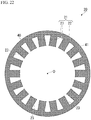
- the adhesion part 41 may be provided on the entire surface of the stacking surface (the surface 22a of the core back part 22) of the electrical steel sheet 40 located at the upper end portion 71. Further, the surface 22a of the core back part 22 of the electrical steel sheet 40 may be entirely adhered to the surface 22a of the core back part 22 of the electrical steel sheets 40 adjacent to each other in the stacking direction.
- the adhesion part 41 may be provided on the entire surface of the stacking surface (the surface 23a of the tooth part 23) of the electrical steel sheet 40 located at the upper end portion 71. Further, the surface 23a of the tooth part 23 of the electrical steel sheet 40 may be entirely adhered to the surface 23a of the tooth part 23 of the electrical steel sheets 40 adjacent to each other in the stacking direction.
- the adhesion part 41 may be provided on the entire surface of the stacking surface (the surface 22a of the core back part 22) of the electrical steel sheet 40 located at the lower end portion 72. Further, the surface 22a of the core back part 22 of the electrical steel sheet 40 may be entirely adhered to the surface 22a of the core back part 22 of the electrical steel sheets 40 adjacent to each other in the stacking direction.
- the adhesion part 41 may be provided on the entire surface of the stacking surface (the surface 23a of the tooth part 23) of the electrical steel sheet 40 located at the lower end portion 72. Further, the surface 23a of the tooth part 23 of the electrical steel sheet 40 may be entirely adhered to the surface 23a of the tooth part 23 of the electrical steel sheets 40 adjacent to each other in the stacking direction.
- the stacking surface of the electrical steel sheet 40 located at the upper end portion 71 in the stacking direction of the stator core 21 among the plurality of electrical steel sheets 40 is entirely adhered to the stacking surface of the electrical steel sheets 40 adjacent to each other in the stacking direction. Further, the stacking surface of the electrical steel sheet 40 located at the lower end portion (the second end portion) 72 of the stator core 21 in the stacking direction among the plurality of electrical steel sheets 40 is entirely adhered to the stacking surface of the electrical steel sheets 40 adjacent to each other in the stacking direction.
- the arrangement regions do not overlap each other in a plan view. At least in some sets of the electrical steel sheets 40, the arrangement regions may not overlap each other in the plan view.
- the shape of the stator core is not limited to the form shown in the above-described embodiment. Specifically, dimensions of an outer diameter and an inner diameter of the stator core, the stacking thickness, the number of slots, a dimensional ratio between the circumferential direction and the radial direction of the tooth part, a dimensional ratio in the radial direction between the tooth part and the core back part, and the like can be arbitrarily designed according to the desired properties of the electric motor.
- a set of two permanent magnets 32 form one magnetic pole
- the present invention is not limited thereto.
- one permanent magnet 32 may form one magnetic pole, or three or more permanent magnets 32 may form one magnetic pole.
- the permanent magnetic electric motor has been described as an example of the electric motor
- the structure of the electric motor is not limited thereto as illustrated below, and various known structures not exemplified below can also be adopted.
- the permanent magnetic electric motor has been described as an example of the synchronous motor, the present invention is not limited thereto.
- the electric motor may be a reluctance motor or an electromagnet field motor (a wound-field motor).
- the electric motor may be an induction motor.
- the AC motor has been described as an example of the electric motor, the present invention is not limited thereto.
- the electric motor may be a DC motor.
- the motor has been described as an example of the electric motor, the present invention is not limited thereto.
- the electric motor may be a generator.
- the laminated core according to the present invention can also be applied to the rotor core.
- the present invention it is possible to provide a laminated core in which the motor characteristics are enhanced and an electric motor including the laminated core. Therefore, the industrial applicability is great.
Landscapes
- Engineering & Computer Science (AREA)
- Power Engineering (AREA)
- Manufacturing & Machinery (AREA)
- Iron Core Of Rotating Electric Machines (AREA)
- Manufacturing Cores, Coils, And Magnets (AREA)
- Manufacture Of Motors, Generators (AREA)
Applications Claiming Priority (2)
| Application Number | Priority Date | Filing Date | Title |
|---|---|---|---|
| JP2018235860 | 2018-12-17 | ||
| PCT/JP2019/049267 WO2020129926A1 (ja) | 2018-12-17 | 2019-12-17 | 積層コアおよび回転電機 |
Publications (2)
| Publication Number | Publication Date |
|---|---|
| EP3902104A1 true EP3902104A1 (de) | 2021-10-27 |
| EP3902104A4 EP3902104A4 (de) | 2022-10-05 |
Family
ID=71101800
Family Applications (1)
| Application Number | Title | Priority Date | Filing Date |
|---|---|---|---|
| EP19898200.1A Pending EP3902104A4 (de) | 2018-12-17 | 2019-12-17 | Laminierter kern und rotierende elektrische maschine |
Country Status (11)
| Country | Link |
|---|---|
| US (1) | US11863017B2 (de) |
| EP (1) | EP3902104A4 (de) |
| JP (1) | JP7288201B2 (de) |
| KR (1) | KR102573694B1 (de) |
| CN (1) | CN113169592B (de) |
| CA (1) | CA3131668C (de) |
| EA (1) | EA202192078A1 (de) |
| MY (1) | MY205931A (de) |
| SG (1) | SG11202108979XA (de) |
| TW (1) | TWI744741B (de) |
| WO (1) | WO2020129926A1 (de) |
Cited By (1)
| Publication number | Priority date | Publication date | Assignee | Title |
|---|---|---|---|---|
| EP4439928A4 (de) * | 2021-11-25 | 2025-04-09 | Nippon Steel Corporation | Blechpaket und rotierende elektrische maschine |
Families Citing this family (19)
| Publication number | Priority date | Publication date | Assignee | Title |
|---|---|---|---|---|
| JP6863525B2 (ja) | 2018-12-17 | 2021-04-21 | 日本製鉄株式会社 | 積層コアおよび回転電機 |
| JP7207429B2 (ja) | 2018-12-17 | 2023-01-18 | 日本製鉄株式会社 | 接着積層コア、その製造方法及び回転電機 |
| EP3902121B1 (de) | 2018-12-17 | 2025-08-13 | Nippon Steel Corporation | Adhäsiv laminierter kern für stator und elektromotor |
| WO2020129923A1 (ja) | 2018-12-17 | 2020-06-25 | 日本製鉄株式会社 | 積層コアおよび回転電機 |
| JP6940007B2 (ja) | 2018-12-17 | 2021-09-22 | 日本製鉄株式会社 | 積層コア、コアブロック、回転電機およびコアブロックの製造方法 |
| RS65460B1 (sr) | 2018-12-17 | 2024-05-31 | Nippon Steel Corp | Laminirano jezgro i električni motor |
| EA202192063A1 (ru) | 2018-12-17 | 2021-11-24 | Ниппон Стил Корпорейшн | Шихтованный сердечник и электродвигатель |
| JP7576981B2 (ja) | 2018-12-17 | 2024-11-01 | 日本製鉄株式会社 | 積層コアおよび回転電機 |
| JP7418350B2 (ja) | 2018-12-17 | 2024-01-19 | 日本製鉄株式会社 | ステータ用接着積層コアおよび回転電機 |
| TWI725670B (zh) | 2018-12-17 | 2021-04-21 | 日商日本製鐵股份有限公司 | 積層鐵芯、其製造方法及旋轉電機 |
| SG11202108923TA (en) | 2018-12-17 | 2021-09-29 | Nippon Steel Corp | Laminated core, laminated core manufacturing method, and electric motor |
| WO2020129937A1 (ja) | 2018-12-17 | 2020-06-25 | 日本製鉄株式会社 | 積層コアおよび回転電機 |
| EA202192064A1 (ru) | 2018-12-17 | 2021-11-24 | Ниппон Стил Корпорейшн | Шихтованный сердечник и электродвигатель |
| CA3131675C (en) | 2018-12-17 | 2024-04-16 | Nippon Steel Corporation | Adhesively-laminated core for stator, method of manufacturing same, and electric motor |
| WO2020129928A1 (ja) | 2018-12-17 | 2020-06-25 | 日本製鉄株式会社 | 積層コアおよび回転電機 |
| CA3131671A1 (en) | 2018-12-17 | 2020-06-25 | Nippon Steel Corporation | Adhesively-laminated core for stator, method of manufacturing the same, and electric motor |
| JP7756026B2 (ja) * | 2022-03-10 | 2025-10-17 | 株式会社三井ハイテック | 積層鉄心、積層鉄心の製造方法および順送り金型装置 |
| DE102024108732A1 (de) | 2024-03-27 | 2025-10-02 | Schaeffler Technologies AG & Co. KG | Verfahren zum Herstellen eines Blechpakets für einen Stator und/oder Rotor einer elektrischen Maschine, sowie eine entsprechende elektrische Maschine |
| JP2026065898A (ja) * | 2024-10-04 | 2026-04-16 | 株式会社エフ・シー・シー | 積層鉄心 |
Family Cites Families (166)
| Publication number | Priority date | Publication date | Assignee | Title |
|---|---|---|---|---|
| JPS5665326A (en) | 1979-10-29 | 1981-06-03 | Tdk Corp | Magnetic core for magnetic head |
| JPS576427A (en) | 1980-06-11 | 1982-01-13 | Canon Inc | Manufacture of magnetic core |
| JPS60170681A (ja) | 1984-02-16 | 1985-09-04 | Nippon Synthetic Chem Ind Co Ltd:The | 接着剤組成物 |
| JPS60186834A (ja) | 1984-03-07 | 1985-09-24 | Toray Ind Inc | 水現像可能な感光性樹脂版材 |
| JPS60186834U (ja) | 1984-05-18 | 1985-12-11 | 株式会社東芝 | 回転電機の固定子鉄心 |
| JPS63207639A (ja) | 1987-02-25 | 1988-08-29 | 日新製鋼株式会社 | 制振鋼板及びその製造方法 |
| JPH03124247A (ja) | 1989-10-05 | 1991-05-27 | Aichi Emerson Electric Co Ltd | 回転電機の固定子 |
| JPH03247683A (ja) | 1990-02-23 | 1991-11-05 | Sumitomo Chem Co Ltd | アクリル系接着剤組成物 |
| JPH0428743U (de) | 1990-05-22 | 1992-03-06 | ||
| JP2897344B2 (ja) | 1990-05-23 | 1999-05-31 | 住友化学工業株式会社 | 熱可塑性樹脂組成物 |
| JPH08996B2 (ja) | 1991-01-24 | 1996-01-10 | 新日本製鐵株式会社 | 溶接性、塗料密着性に優れた表面処理鋼板の製造方法 |
| US5448119A (en) | 1991-03-29 | 1995-09-05 | Nagano Nidec Corporation | Spindle motor |
| US5142178A (en) | 1991-04-12 | 1992-08-25 | Emerson Electric Co. | Apparatus for aligning stacked laminations of a dynamoelectric machine |
| JPH0614481A (ja) | 1992-06-25 | 1994-01-21 | Mitsubishi Electric Corp | 電機子鉄心 |
| JPH07118620A (ja) | 1993-10-22 | 1995-05-09 | Nippon Zeon Co Ltd | エポキシ系接着剤組成物 |
| JPH07298567A (ja) | 1994-04-26 | 1995-11-10 | Honda Motor Co Ltd | 積層鋼板の接着用加熱装置 |
| JPH08259899A (ja) | 1995-03-23 | 1996-10-08 | Three Bond Co Ltd | シアノアクリレート系接着剤組成物 |
| JP3369941B2 (ja) | 1997-11-27 | 2003-01-20 | 日本鋼管株式会社 | 接着強度、耐食性及び耐ブロッキング性に優れた接着鉄芯用電磁鋼板の製造方法 |
| JP2000050539A (ja) | 1998-07-28 | 2000-02-18 | Toshiba Corp | 回転電機の固定子鉄心、固定子鉄心用鋼板部品、固定子鉄心の製造方法および固定子鉄心用鋼板部品の製造方法 |
| JP2000152570A (ja) | 1998-11-06 | 2000-05-30 | Toshiba Corp | 磁石鉄心の製造方法 |
| JP2001115125A (ja) | 1999-10-01 | 2001-04-24 | Three M Innovative Properties Co | ネオジム磁石用接着剤及びモータ |
| FR2803126B1 (fr) | 1999-12-23 | 2006-04-14 | Valeo Equip Electr Moteur | Alternateur pour vehicule a stator generant peu de bruit magnetique |
| JP2001251828A (ja) | 2000-03-02 | 2001-09-14 | Moric Co Ltd | 内燃機関用多極磁石式発電機 |
| JP2002078257A (ja) | 2000-08-24 | 2002-03-15 | Mitsubishi Electric Corp | モーター及びそのローター |
| JP2002164224A (ja) | 2000-08-30 | 2002-06-07 | Mitsui Chemicals Inc | 磁性基材およびその製造方法 |
| JP4020236B2 (ja) * | 2000-09-18 | 2007-12-12 | 電気化学工業株式会社 | 硬化性樹脂組成物、硬化体、接着剤組成物及び接合体 |
| JP2002105283A (ja) | 2000-09-28 | 2002-04-10 | Nhk Spring Co Ltd | エポキシ樹脂分散体およびそれを用いた銅張り積層板及び銅張り金属基板 |
| JP2002125341A (ja) * | 2000-10-16 | 2002-04-26 | Denki Kagaku Kogyo Kk | ステーター及びそれを用いたモーター |
| JP3725776B2 (ja) | 2000-11-10 | 2005-12-14 | 新日本製鐵株式会社 | 積層鉄芯の製造方法およびその製造装置 |
| JP2002151335A (ja) * | 2000-11-10 | 2002-05-24 | Nippon Steel Corp | 鉄損特性の優れた積層鉄芯およびその製造方法 |
| EP1241773B1 (de) | 2001-03-14 | 2012-09-12 | Nissan Motor Co., Ltd. | Drehende elektrische Maschine mit Spalttopf |
| JP4076323B2 (ja) | 2001-05-08 | 2008-04-16 | 電気化学工業株式会社 | 硬化性樹脂組成物、硬化体、接着剤組成物及び接合体 |
| JP4018885B2 (ja) | 2001-05-25 | 2007-12-05 | 株式会社三井ハイテック | 積層鉄心 |
| JP3594003B2 (ja) | 2001-08-28 | 2004-11-24 | 日産自動車株式会社 | 回転電機及びその製造方法 |
| JP2003199303A (ja) | 2001-12-27 | 2003-07-11 | Matsushita Electric Ind Co Ltd | モータの製造方法 |
| JP4165072B2 (ja) | 2002-01-15 | 2008-10-15 | 日立化成工業株式会社 | 接着剤組成物、接着フィルム、半導体搭載用配線基板及び半導体装置とその製造方法 |
| JP2003219585A (ja) | 2002-01-22 | 2003-07-31 | Mitsubishi Electric Corp | 積層鉄心およびその製造方法 |
| JP3771933B2 (ja) | 2002-03-08 | 2006-05-10 | Jfeスチール株式会社 | 積層コア用材料及びその製造方法 |
| JP2003284274A (ja) | 2002-03-22 | 2003-10-03 | Nippon Steel Corp | 永久磁石同期モータのロータ |
| JP2004088970A (ja) | 2002-08-29 | 2004-03-18 | Hitachi Ltd | 積層鉄心とそれを用いた回転電機およびトランス |
| JP2004111509A (ja) | 2002-09-17 | 2004-04-08 | Nippon Steel Corp | 鉄損特性の優れた積層鉄芯及びその製造方法 |
| JP4222000B2 (ja) | 2002-10-29 | 2009-02-12 | Nok株式会社 | 磁気エンコーダ |
| JP3791492B2 (ja) | 2002-12-25 | 2006-06-28 | 株式会社日立製作所 | 回転電機及び電動車両並びに樹脂のインサート成形方法 |
| JP2004222409A (ja) * | 2003-01-15 | 2004-08-05 | Nippon Steel Corp | ステータ鉄心 |
| JP4143090B2 (ja) | 2003-02-03 | 2008-09-03 | 新日本製鐵株式会社 | 接着用表面被覆電磁鋼板 |
| JP4987216B2 (ja) | 2003-06-25 | 2012-07-25 | Jfeスチール株式会社 | 寸法精度に優れた積層コア及びその製造方法 |
| JP2005269732A (ja) | 2004-03-17 | 2005-09-29 | Nippon Steel Corp | 鉄芯の製造方法とその方法に適した装置 |
| JP2005268589A (ja) | 2004-03-19 | 2005-09-29 | Nippon Steel Corp | エネルギー変換機器用磁性部材の簡易製造方法 |
| JP2006254530A (ja) | 2005-03-08 | 2006-09-21 | Mitsubishi Electric Corp | 電動機 |
| JP2006288114A (ja) | 2005-04-01 | 2006-10-19 | Mitsui High Tec Inc | 積層鉄心、及び積層鉄心の製造方法 |
| JP2006353001A (ja) | 2005-06-15 | 2006-12-28 | Japan Servo Co Ltd | 積層鉄心とその製造方法及び製造装置 |
| JP4687289B2 (ja) | 2005-07-08 | 2011-05-25 | 東洋紡績株式会社 | ポリアミド系混合樹脂積層フィルムロール、およびその製造方法 |
| JP4586669B2 (ja) | 2005-08-01 | 2010-11-24 | 住友金属工業株式会社 | 回転子用無方向性電磁鋼板の製造方法 |
| JP2007053896A (ja) | 2005-08-17 | 2007-03-01 | Minebea Co Ltd | ステータユニット及びその製造方法 |
| JP4236056B2 (ja) | 2006-02-08 | 2009-03-11 | 三菱電機株式会社 | 磁石発電機 |
| KR100808194B1 (ko) | 2006-05-19 | 2008-02-29 | 엘지전자 주식회사 | 아우터 로터 타입 모터의 스테이터 |
| JP4938389B2 (ja) | 2006-09-06 | 2012-05-23 | 三菱電機株式会社 | 積層コアおよびステータ |
| WO2008044740A1 (en) * | 2006-10-13 | 2008-04-17 | Mitsui High-Tec, Inc. | Laminated iron core, and its manufacturing method |
| ITMI20070508A1 (it) | 2007-03-14 | 2008-09-15 | Corrada Spa | Articolo laminare per uso elettrico procedimento e macchine per realizzare detto articolo laminare |
| CN101755328B (zh) | 2007-07-19 | 2011-08-31 | 积水化学工业株式会社 | 电子器件用胶粘剂 |
| JP5211651B2 (ja) * | 2007-11-15 | 2013-06-12 | パナソニック株式会社 | モータおよびそれを用いた電子機器 |
| JP5172367B2 (ja) | 2008-01-23 | 2013-03-27 | 三菱電機株式会社 | 積層コア、積層コアの製造方法、積層コアの製造装置およびステータ |
| JP5478266B2 (ja) | 2008-02-15 | 2014-04-23 | 株式会社クラレ | 硬化性樹脂組成物および樹脂硬化物 |
| JP5428218B2 (ja) | 2008-06-23 | 2014-02-26 | 富士電機株式会社 | 永久磁石形回転電機の回転子構造 |
| WO2010082482A1 (ja) | 2009-01-15 | 2010-07-22 | 株式会社カネカ | 硬化性組成物、その硬化物、及びその製造方法 |
| JP5084770B2 (ja) | 2009-03-13 | 2012-11-28 | 三菱電機株式会社 | 電動機及び圧縮機及び空気調和機 |
| JP2010239691A (ja) | 2009-03-30 | 2010-10-21 | Denso Corp | 回転電機の固定子及び回転電機 |
| JP5444812B2 (ja) | 2009-04-22 | 2014-03-19 | Jfeスチール株式会社 | 高速モータ用コア材料 |
| BRPI1010688B1 (pt) | 2009-06-17 | 2019-11-19 | Nippon Steel & Sumitomo Metal Corp | chapa de aço eletromagnético tendo revestimento isolante e método de produção da mesma |
| JP2011023523A (ja) * | 2009-07-15 | 2011-02-03 | Nippon Steel Corp | 良好な熱伝導性を有する電磁鋼板積層コアおよびその製造方法 |
| EP2460652B1 (de) | 2009-07-31 | 2016-02-17 | Nippon Steel & Sumitomo Metal Corporation | Laminierte stahlplatte |
| BE1019128A3 (nl) | 2009-11-06 | 2012-03-06 | Atlas Copco Airpower Nv | Gelamelleerde kern van een magneetlager en werkwijze voor het vervaardigen van zulke gelamelleerde kern. |
| JP5716339B2 (ja) | 2010-01-08 | 2015-05-13 | 大日本印刷株式会社 | 粘接着シートおよびそれを用いた接着方法 |
| JP5844963B2 (ja) | 2010-03-19 | 2016-01-20 | 積水化学工業株式会社 | 電子部品用接着剤 |
| JP5459110B2 (ja) | 2010-06-30 | 2014-04-02 | 株式会社デンソー | 回転電機の固定子 |
| JP2012029494A (ja) | 2010-07-26 | 2012-02-09 | Nissan Motor Co Ltd | 電動機およびその製造方法 |
| JP2012061820A (ja) | 2010-09-17 | 2012-03-29 | Dainippon Printing Co Ltd | 繊維強化複合材料の賦型方法 |
| JP2012120299A (ja) | 2010-11-30 | 2012-06-21 | Mitsubishi Electric Corp | ステータコア、回転電機およびステータコアの製造方法 |
| JP2012165494A (ja) * | 2011-02-03 | 2012-08-30 | Mitsui High Tec Inc | 積層鉄心及びその製造方法 |
| JP5915075B2 (ja) | 2011-10-21 | 2016-05-11 | Jfeスチール株式会社 | 積層コアの製造方法 |
| CN104144797B (zh) | 2012-02-29 | 2016-06-22 | 株式会社普利司通 | 轮胎 |
| JP5966445B2 (ja) | 2012-03-01 | 2016-08-10 | 住友ベークライト株式会社 | 固定用樹脂組成物、ロータ、および自動車 |
| IN2014DN07130A (de) | 2012-03-01 | 2015-04-24 | Sumitomo Bakelite Co | |
| JP2013194130A (ja) | 2012-03-19 | 2013-09-30 | Nitto Denko Corp | 塗膜保護シート |
| JP2013253153A (ja) | 2012-06-06 | 2013-12-19 | Mitsubishi Chemicals Corp | エポキシ樹脂、エポキシ樹脂組成物、硬化物及び光学部材 |
| JP2014014231A (ja) * | 2012-07-04 | 2014-01-23 | Mitsubishi Heavy Ind Ltd | 電動モータ |
| JP2014019777A (ja) | 2012-07-18 | 2014-02-03 | Nitto Denko Corp | 表面保護シート |
| JP6134497B2 (ja) | 2012-11-08 | 2017-05-24 | 京セラ株式会社 | 積層コアの製造方法 |
| WO2014102915A1 (ja) | 2012-12-26 | 2014-07-03 | 株式会社 日立製作所 | 低融点ガラス樹脂複合材料と、それを用いた電子・電気機器 |
| JP5896937B2 (ja) | 2013-02-08 | 2016-03-30 | 三菱電機株式会社 | 分割鉄心、及びこの分割鉄心を用いた固定子、並びにこの固定子を備えた回転電機 |
| JP2015012756A (ja) | 2013-07-01 | 2015-01-19 | 日本精工株式会社 | ダイレクトドライブモータ |
| US9490667B2 (en) | 2013-07-23 | 2016-11-08 | General Electric Company | Apparatus and system for attaching integral spacers to laminations |
| KR101539849B1 (ko) * | 2013-09-23 | 2015-07-28 | 뉴모텍(주) | 절연 코팅에 적합한 구조를 갖는 모터의 적층 코어 |
| JP6164039B2 (ja) | 2013-10-21 | 2017-07-19 | アイシン・エィ・ダブリュ株式会社 | 積層鉄心の製造方法 |
| JP6066936B2 (ja) * | 2014-01-17 | 2017-01-25 | 三菱電機株式会社 | 積層鉄心の製造方法、固定子の製造方法 |
| JP6065032B2 (ja) | 2014-01-29 | 2017-01-25 | Jfeスチール株式会社 | 積層鉄心製造方法および積層鉄心 |
| JP6064923B2 (ja) | 2014-01-29 | 2017-01-25 | Jfeスチール株式会社 | 積層鉄心の製造方法 |
| JP6248711B2 (ja) | 2014-03-06 | 2017-12-20 | 株式会社デンソー | 回転電機の固定子 |
| JP6383202B2 (ja) | 2014-07-24 | 2018-08-29 | 株式会社三井ハイテック | 積層鉄心の製造方法及び積層鉄心 |
| JP6037055B2 (ja) | 2014-07-29 | 2016-11-30 | Jfeスチール株式会社 | 積層用電磁鋼板、積層型電磁鋼板、積層型電磁鋼板の製造方法、および自動車モーター用鉄心 |
| JP6431316B2 (ja) | 2014-08-26 | 2018-11-28 | 日東シンコー株式会社 | モーター用絶縁シート |
| JP6479392B2 (ja) | 2014-09-30 | 2019-03-06 | 株式会社三井ハイテック | 積層鉄心及びその製造方法 |
| JP6303978B2 (ja) | 2014-10-27 | 2018-04-04 | トヨタ自動車株式会社 | 回転電機のステータ |
| JP6343556B2 (ja) * | 2014-12-09 | 2018-06-13 | 株式会社三井ハイテック | 積層鉄心用積層体及びその製造方法並びに積層鉄心の製造方法 |
| JP6587800B2 (ja) | 2014-12-26 | 2019-10-09 | Jfeスチール株式会社 | 積層鉄心の製造方法 |
| JP5958565B2 (ja) * | 2015-01-14 | 2016-08-02 | Jfeスチール株式会社 | 打抜き加工方法、打抜き加工装置、および積層鉄心の製造方法 |
| WO2016113876A1 (ja) | 2015-01-15 | 2016-07-21 | 三菱電機株式会社 | 回転電機 |
| JP2016140134A (ja) | 2015-01-26 | 2016-08-04 | アイシン・エィ・ダブリュ株式会社 | モータコアおよびモータコアの製造方法 |
| JP6506570B2 (ja) * | 2015-03-02 | 2019-04-24 | 株式会社日立産機システム | 永久磁石回転電機 |
| JP6249417B2 (ja) | 2015-03-09 | 2017-12-20 | 三菱電機株式会社 | 回転電機および電動パワーステアリング装置 |
| JP6432397B2 (ja) | 2015-03-12 | 2018-12-05 | アイシン・エィ・ダブリュ株式会社 | モータの製造方法およびモータコア |
| JP6495092B2 (ja) | 2015-05-07 | 2019-04-03 | 株式会社三井ハイテック | 分割型積層鉄心及びその製造方法 |
| JP2016226170A (ja) | 2015-05-29 | 2016-12-28 | トヨタ自動車株式会社 | 電動機用積層コア |
| JP6627270B2 (ja) | 2015-06-12 | 2020-01-08 | 住友ベークライト株式会社 | 整流子 |
| JP2017011863A (ja) | 2015-06-22 | 2017-01-12 | 新日鐵住金株式会社 | モータ鉄心用積層電磁鋼板およびその製造方法 |
| JP2017028911A (ja) | 2015-07-24 | 2017-02-02 | 日東シンコー株式会社 | 回転電機用絶縁紙 |
| CN108028557B (zh) | 2015-08-21 | 2020-04-21 | 三菱电机株式会社 | 永磁铁嵌入式电动机、压缩机以及制冷空调装置 |
| JP6429129B2 (ja) | 2015-08-26 | 2018-11-28 | 日産自動車株式会社 | ロータの製造方法 |
| WO2017061625A1 (ja) | 2015-10-07 | 2017-04-13 | 大日本印刷株式会社 | 接着シートセットおよび物品の製造方法 |
| JP6560588B2 (ja) | 2015-10-08 | 2019-08-14 | 住友電気工業株式会社 | 誘導加熱装置、及び発電システム |
| JP2017075279A (ja) | 2015-10-16 | 2017-04-20 | 株式会社菱晃 | 接着剤及び接合体 |
| KR101923359B1 (ko) | 2015-11-25 | 2018-11-28 | 미쓰비시덴키 가부시키가이샤 | 회전 전기 및 회전 전기의 제조 방법 |
| WO2017090571A1 (ja) * | 2015-11-27 | 2017-06-01 | 日本電産株式会社 | モータおよびモータの製造方法 |
| CN108353497A (zh) | 2015-12-18 | 2018-07-31 | Dic株式会社 | 热固性粘接片、带有增强部的柔性印刷配线板、其制造方法以及电子设备 |
| JP6680351B2 (ja) | 2016-02-25 | 2020-04-15 | 日立化成株式会社 | エポキシ樹脂組成物、半硬化エポキシ樹脂組成物、硬化エポキシ樹脂組成物、成形物及び成形硬化物 |
| WO2017170957A1 (ja) | 2016-03-31 | 2017-10-05 | デンカ株式会社 | 組成物 |
| CN109155574B (zh) | 2016-05-20 | 2020-11-06 | 日本电产株式会社 | 定子铁芯的制造方法 |
| CN107674499B (zh) | 2016-08-01 | 2021-07-13 | 株式会社理光 | 墨水,墨水容器,液体排出装置,图像形成方法及其装置 |
| JP6874550B2 (ja) | 2016-08-01 | 2021-05-19 | 株式会社リコー | インク、インク容器、画像形成方法、画像形成装置、画像形成物、及び液体吐出装置 |
| JP6376706B2 (ja) | 2016-08-29 | 2018-08-22 | 本田技研工業株式会社 | 積層鋼板の製造方法および製造装置 |
| WO2018043429A1 (ja) | 2016-09-01 | 2018-03-08 | 三菱電機株式会社 | 積層鉄心、積層鉄心の製造方法、および積層鉄心を用いた電機子 |
| JP6848314B2 (ja) | 2016-10-03 | 2021-03-24 | 日本製鉄株式会社 | ステータコアおよび回転電機 |
| JP6724735B2 (ja) * | 2016-11-08 | 2020-07-15 | トヨタ自動車株式会社 | 回転電機のステータ |
| KR101874918B1 (ko) | 2016-11-15 | 2018-07-06 | 지에스칼텍스 주식회사 | 저비중 폴리프로필렌 수지 조성물 및 이를 이용한 자동차 내장재용 성형품 |
| CN108155730B (zh) | 2016-12-06 | 2022-02-25 | 松下电器产业株式会社 | 铁芯和电机 |
| JP6905905B2 (ja) | 2016-12-06 | 2021-07-21 | パナソニック株式会社 | 鉄心およびモータ |
| EP3553799B1 (de) | 2016-12-07 | 2021-07-14 | Panasonic Corporation | Methode zur herstellung eines eisenkerns |
| JP6543608B2 (ja) | 2016-12-22 | 2019-07-10 | 株式会社三井ハイテック | 積層鉄心の製造方法及び積層鉄心の製造装置 |
| JP6656428B2 (ja) | 2017-01-27 | 2020-03-04 | 三菱電機株式会社 | 固定子、電動機、圧縮機、および冷凍空調装置 |
| FR3062970B1 (fr) | 2017-02-13 | 2021-07-23 | Valeo Equip Electr Moteur | Stator de machine electrique tournante |
| JP2018138634A (ja) | 2017-02-24 | 2018-09-06 | 三菱ケミカル株式会社 | 樹脂組成物および該樹脂組成物を用いた半導体装置 |
| JP6866696B2 (ja) | 2017-03-07 | 2021-04-28 | 日本製鉄株式会社 | 無方向性電磁鋼板およびその製造方法、並びにモータコアおよびその製造方法 |
| JPWO2018199269A1 (ja) | 2017-04-26 | 2020-04-23 | 東亞合成株式会社 | 接着剤組成物 |
| CN110622393B (zh) | 2017-05-10 | 2022-05-13 | 三菱电机株式会社 | 定子、电动机、压缩机、制冷空调装置及定子的制造方法 |
| WO2018216565A1 (ja) | 2017-05-23 | 2018-11-29 | 株式会社スリーボンド | 積層鋼板の製造方法、積層鋼板、モータおよび積層鋼板用接着剤組成物 |
| JP2018201303A (ja) | 2017-05-29 | 2018-12-20 | 日本電産株式会社 | モータ |
| JP6972138B2 (ja) | 2017-08-25 | 2021-11-24 | 三菱電機株式会社 | 分割コア連結体および電機子の製造方法 |
| DE102017010685A1 (de) | 2017-11-16 | 2019-05-16 | Wieland-Werke Ag | Kurzschlussläufer und Verfahren zur Herstellung eines Kurzschlussläufers |
| JP6826566B2 (ja) | 2018-08-06 | 2021-02-03 | 本田技研工業株式会社 | 回転電機用ステータコアおよび回転電機 |
| CA3131671A1 (en) | 2018-12-17 | 2020-06-25 | Nippon Steel Corporation | Adhesively-laminated core for stator, method of manufacturing the same, and electric motor |
| JP6863525B2 (ja) | 2018-12-17 | 2021-04-21 | 日本製鉄株式会社 | 積層コアおよび回転電機 |
| CA3131675C (en) | 2018-12-17 | 2024-04-16 | Nippon Steel Corporation | Adhesively-laminated core for stator, method of manufacturing same, and electric motor |
| EP3902121B1 (de) | 2018-12-17 | 2025-08-13 | Nippon Steel Corporation | Adhäsiv laminierter kern für stator und elektromotor |
| JP7207429B2 (ja) | 2018-12-17 | 2023-01-18 | 日本製鉄株式会社 | 接着積層コア、その製造方法及び回転電機 |
| RS65460B1 (sr) | 2018-12-17 | 2024-05-31 | Nippon Steel Corp | Laminirano jezgro i električni motor |
| JP7576981B2 (ja) | 2018-12-17 | 2024-11-01 | 日本製鉄株式会社 | 積層コアおよび回転電機 |
| SG11202108923TA (en) | 2018-12-17 | 2021-09-29 | Nippon Steel Corp | Laminated core, laminated core manufacturing method, and electric motor |
| EA202192063A1 (ru) | 2018-12-17 | 2021-11-24 | Ниппон Стил Корпорейшн | Шихтованный сердечник и электродвигатель |
| EA202192064A1 (ru) | 2018-12-17 | 2021-11-24 | Ниппон Стил Корпорейшн | Шихтованный сердечник и электродвигатель |
| WO2020129928A1 (ja) | 2018-12-17 | 2020-06-25 | 日本製鉄株式会社 | 積層コアおよび回転電機 |
| TWI725670B (zh) | 2018-12-17 | 2021-04-21 | 日商日本製鐵股份有限公司 | 積層鐵芯、其製造方法及旋轉電機 |
| JP6940007B2 (ja) | 2018-12-17 | 2021-09-22 | 日本製鉄株式会社 | 積層コア、コアブロック、回転電機およびコアブロックの製造方法 |
| KR20240052877A (ko) | 2018-12-17 | 2024-04-23 | 닛폰세이테츠 가부시키가이샤 | 스테이터용 접착 적층 코어 및 회전 전기 기기 |
| WO2020129923A1 (ja) | 2018-12-17 | 2020-06-25 | 日本製鉄株式会社 | 積層コアおよび回転電機 |
| JP7418350B2 (ja) | 2018-12-17 | 2024-01-19 | 日本製鉄株式会社 | ステータ用接着積層コアおよび回転電機 |
| WO2020129937A1 (ja) | 2018-12-17 | 2020-06-25 | 日本製鉄株式会社 | 積層コアおよび回転電機 |
-
2019
- 2019-12-17 KR KR1020217015790A patent/KR102573694B1/ko active Active
- 2019-12-17 SG SG11202108979XA patent/SG11202108979XA/en unknown
- 2019-12-17 TW TW108146182A patent/TWI744741B/zh active
- 2019-12-17 US US17/293,795 patent/US11863017B2/en active Active
- 2019-12-17 EP EP19898200.1A patent/EP3902104A4/de active Pending
- 2019-12-17 CN CN201980078709.4A patent/CN113169592B/zh active Active
- 2019-12-17 EA EA202192078A patent/EA202192078A1/ru unknown
- 2019-12-17 WO PCT/JP2019/049267 patent/WO2020129926A1/ja not_active Ceased
- 2019-12-17 MY MYPI2021005323A patent/MY205931A/en unknown
- 2019-12-17 CA CA3131668A patent/CA3131668C/en active Active
- 2019-12-17 JP JP2020561427A patent/JP7288201B2/ja active Active
Cited By (1)
| Publication number | Priority date | Publication date | Assignee | Title |
|---|---|---|---|---|
| EP4439928A4 (de) * | 2021-11-25 | 2025-04-09 | Nippon Steel Corporation | Blechpaket und rotierende elektrische maschine |
Also Published As
| Publication number | Publication date |
|---|---|
| CA3131668A1 (en) | 2020-06-25 |
| MY205931A (en) | 2024-11-21 |
| BR112021008058A2 (pt) | 2021-08-03 |
| EA202192078A1 (ru) | 2021-11-11 |
| CN113169592B (zh) | 2024-07-23 |
| WO2020129926A1 (ja) | 2020-06-25 |
| US20220014052A1 (en) | 2022-01-13 |
| SG11202108979XA (en) | 2021-09-29 |
| EP3902104A4 (de) | 2022-10-05 |
| CN113169592A (zh) | 2021-07-23 |
| US11863017B2 (en) | 2024-01-02 |
| JPWO2020129926A1 (ja) | 2021-11-04 |
| CA3131668C (en) | 2023-11-07 |
| KR102573694B1 (ko) | 2023-09-04 |
| KR20210080522A (ko) | 2021-06-30 |
| TW202030082A (zh) | 2020-08-16 |
| JP7288201B2 (ja) | 2023-06-07 |
| TWI744741B (zh) | 2021-11-01 |
Similar Documents
| Publication | Publication Date | Title |
|---|---|---|
| US11863017B2 (en) | Laminated core and electric motor | |
| EP3902105B1 (de) | Laminierter kern und rotierende elektrische maschine | |
| CA3131661C (en) | Laminated core and electric motor | |
| JP7576981B2 (ja) | 積層コアおよび回転電機 | |
| EP3902113B1 (de) | Laminierter kern und elektromotor | |
| EP3902111A1 (de) | Laminierter kern und rotierende elektrische maschine | |
| EP3902108B1 (de) | Laminierter kern und rotierende elektrische maschine | |
| JP2023017058A (ja) | ステータ用接着積層コア | |
| EP3993224A1 (de) | Kernblock, gestapelter kern und rotierende elektrische maschine |
Legal Events
| Date | Code | Title | Description |
|---|---|---|---|
| STAA | Information on the status of an ep patent application or granted ep patent |
Free format text: STATUS: THE INTERNATIONAL PUBLICATION HAS BEEN MADE |
|
| PUAI | Public reference made under article 153(3) epc to a published international application that has entered the european phase |
Free format text: ORIGINAL CODE: 0009012 |
|
| STAA | Information on the status of an ep patent application or granted ep patent |
Free format text: STATUS: REQUEST FOR EXAMINATION WAS MADE |
|
| 17P | Request for examination filed |
Effective date: 20210626 |
|
| AK | Designated contracting states |
Kind code of ref document: A1 Designated state(s): AL AT BE BG CH CY CZ DE DK EE ES FI FR GB GR HR HU IE IS IT LI LT LU LV MC MK MT NL NO PL PT RO RS SE SI SK SM TR |
|
| DAV | Request for validation of the european patent (deleted) | ||
| DAX | Request for extension of the european patent (deleted) | ||
| A4 | Supplementary search report drawn up and despatched |
Effective date: 20220905 |
|
| RIC1 | Information provided on ipc code assigned before grant |
Ipc: H02K 15/02 20060101ALN20220830BHEP Ipc: H02K 1/276 20220101ALN20220830BHEP Ipc: H02K 1/16 20060101ALI20220830BHEP Ipc: H02K 1/14 20060101ALI20220830BHEP Ipc: H02K 1/02 20060101ALI20220830BHEP Ipc: H01F 3/02 20060101ALI20220830BHEP Ipc: H01F 27/245 20060101ALI20220830BHEP Ipc: H01F 27/24 20060101ALI20220830BHEP Ipc: H02K 1/18 20060101AFI20220830BHEP |