EP4066064B1 - System zum trocknen von tinte im digitaldruck mit infrarotstrahlung, die von in einem itm eingebetteten partikeln absorbiert wird - Google Patents
System zum trocknen von tinte im digitaldruck mit infrarotstrahlung, die von in einem itm eingebetteten partikeln absorbiert wird Download PDFInfo
- Publication number
- EP4066064B1 EP4066064B1 EP20894753.1A EP20894753A EP4066064B1 EP 4066064 B1 EP4066064 B1 EP 4066064B1 EP 20894753 A EP20894753 A EP 20894753A EP 4066064 B1 EP4066064 B1 EP 4066064B1
- Authority
- EP
- European Patent Office
- Prior art keywords
- blanket
- temperature
- ink
- dryer
- layer
- Prior art date
- Legal status (The legal status is an assumption and is not a legal conclusion. Google has not performed a legal analysis and makes no representation as to the accuracy of the status listed.)
- Active
Links
Images

Classifications
-
- B—PERFORMING OPERATIONS; TRANSPORTING
- B41—PRINTING; LINING MACHINES; TYPEWRITERS; STAMPS
- B41J—TYPEWRITERS; SELECTIVE PRINTING MECHANISMS, i.e. MECHANISMS PRINTING OTHERWISE THAN FROM A FORME; CORRECTION OF TYPOGRAPHICAL ERRORS
- B41J2/00—Typewriters or selective printing mechanisms characterised by the printing or marking process for which they are designed
- B41J2/005—Typewriters or selective printing mechanisms characterised by the printing or marking process for which they are designed characterised by bringing liquid or particles selectively into contact with a printing material
- B41J2/0057—Typewriters or selective printing mechanisms characterised by the printing or marking process for which they are designed characterised by bringing liquid or particles selectively into contact with a printing material where an intermediate transfer member receives the ink before transferring it on the printing material
-
- B—PERFORMING OPERATIONS; TRANSPORTING
- B41—PRINTING; LINING MACHINES; TYPEWRITERS; STAMPS
- B41J—TYPEWRITERS; SELECTIVE PRINTING MECHANISMS, i.e. MECHANISMS PRINTING OTHERWISE THAN FROM A FORME; CORRECTION OF TYPOGRAPHICAL ERRORS
- B41J11/00—Devices or arrangements of selective printing mechanisms, e.g. ink-jet printers or thermal printers, for supporting or handling copy material in sheet or web form
- B41J11/0015—Devices or arrangements of selective printing mechanisms, e.g. ink-jet printers or thermal printers, for supporting or handling copy material in sheet or web form for treating before, during or after printing or for uniform coating or laminating the copy material before or after printing
- B41J11/002—Curing or drying the ink on the copy materials, e.g. by heating or irradiating
- B41J11/0021—Curing or drying the ink on the copy materials, e.g. by heating or irradiating using irradiation
- B41J11/00216—Curing or drying the ink on the copy materials, e.g. by heating or irradiating using irradiation using infrared [IR] radiation or microwaves
-
- B—PERFORMING OPERATIONS; TRANSPORTING
- B41—PRINTING; LINING MACHINES; TYPEWRITERS; STAMPS
- B41M—PRINTING, DUPLICATING, MARKING, OR COPYING PROCESSES; COLOUR PRINTING
- B41M5/00—Duplicating or marking methods; Sheet materials for use therein
- B41M5/025—Duplicating or marking methods; Sheet materials for use therein by transferring ink from the master sheet
-
- B—PERFORMING OPERATIONS; TRANSPORTING
- B41—PRINTING; LINING MACHINES; TYPEWRITERS; STAMPS
- B41M—PRINTING, DUPLICATING, MARKING, OR COPYING PROCESSES; COLOUR PRINTING
- B41M5/00—Duplicating or marking methods; Sheet materials for use therein
- B41M5/025—Duplicating or marking methods; Sheet materials for use therein by transferring ink from the master sheet
- B41M5/0256—Duplicating or marking methods; Sheet materials for use therein by transferring ink from the master sheet the transferable ink pattern being obtained by means of a computer driven printer, e.g. an ink jet or laser printer, or by electrographic means
-
- B—PERFORMING OPERATIONS; TRANSPORTING
- B41—PRINTING; LINING MACHINES; TYPEWRITERS; STAMPS
- B41M—PRINTING, DUPLICATING, MARKING, OR COPYING PROCESSES; COLOUR PRINTING
- B41M5/00—Duplicating or marking methods; Sheet materials for use therein
- B41M5/025—Duplicating or marking methods; Sheet materials for use therein by transferring ink from the master sheet
- B41M5/03—Duplicating or marking methods; Sheet materials for use therein by transferring ink from the master sheet by pressure
-
- B—PERFORMING OPERATIONS; TRANSPORTING
- B41—PRINTING; LINING MACHINES; TYPEWRITERS; STAMPS
- B41M—PRINTING, DUPLICATING, MARKING, OR COPYING PROCESSES; COLOUR PRINTING
- B41M7/00—After-treatment of prints, e.g. heating, irradiating, setting of the ink, protection of the printed stock
- B41M7/009—After-treatment of prints, e.g. heating, irradiating, setting of the ink, protection of the printed stock using thermal means, e.g. infrared radiation, heat
-
- G—PHYSICS
- G03—PHOTOGRAPHY; CINEMATOGRAPHY; ANALOGOUS TECHNIQUES USING WAVES OTHER THAN OPTICAL WAVES; ELECTROGRAPHY; HOLOGRAPHY
- G03G—ELECTROGRAPHY; ELECTROPHOTOGRAPHY; MAGNETOGRAPHY
- G03G15/00—Apparatus for electrographic processes using a charge pattern
- G03G15/14—Apparatus for electrographic processes using a charge pattern for transferring a pattern to a second base
- G03G15/16—Apparatus for electrographic processes using a charge pattern for transferring a pattern to a second base of a toner pattern, e.g. a powder pattern, e.g. magnetic transfer
- G03G15/1605—Apparatus for electrographic processes using a charge pattern for transferring a pattern to a second base of a toner pattern, e.g. a powder pattern, e.g. magnetic transfer using at least one intermediate support
- G03G15/162—Apparatus for electrographic processes using a charge pattern for transferring a pattern to a second base of a toner pattern, e.g. a powder pattern, e.g. magnetic transfer using at least one intermediate support details of the the intermediate support, e.g. chemical composition
Definitions
- the present invention relates generally to digital printing processes, and particularly to methods and systems for drying ink applied to a surface during a digital printing process.
- Optical radiation such as infrared (IR) and near-IR radiation, has been used for drying ink in various printing processes.
- U.S. Patent Application Publication 2012/0249630 describes a process for printing an image including printing a substrate with an aqueous inkjet ink and drying the printed image with a near-infrared drying system.
- Various embodiments provide a process for inkjet printing and drying inks with improved absorption in the near-IR region of the spectrum for improved drying performance of aqueous, hypsochromic inks, and an inkjet ink set with improved balanced near-IR drying of black and yellow inkjet inks.
- WO 2018/100541 A1 discloses a system comprising a flexible intermediate transfer member, an illumination assembly and a temperature control assembly.
- Embodiments of the present invention that are described hereinbelow provide improved techniques for drying ink applied to a surface of a substrate during a digital printing process.
- a digital printing system comprises a movable flexible intermediate transfer member (ITM), also referred to herein as a blanket, an image forming station for applying ink droplets to the ITM, an illumination assembly, and a temperature control assembly.
- the illumination assembly is configured to direct infrared (IR) radiation to the ITM.
- the ITM comprises a multi-layered stack comprising (i) a release layer, which is transparent to the IR radiation and is located at an outer surface of the ITM, facing the illumination assembly.
- the release layer is configured to receive ink droplets from print bars of the image forming station, such that, when the ITM moves, the print bars form multiple ink images at respective sections of the release layer.
- the ITM is configured to transfer the ink images to a target substrate, such as sheets or a continuous web.
- the ITM further comprises a layer, also referred to herein as an "IR layer,” which is coupled to the release layer and is substantially opaque to the IR radiation.
- the IR layer has a matrix comprising a suitable type of silicone, and carbon-black (CB) particles embedded within the matrix of the IR layer.
- the IR layer is configured to receive the IR radiation passing through the release layer, and, in response to the IR radiation, the CB particles are configured to heat at least the IR layer and the release layer of the ITM, so as to dry the ink droplets applied to the release layer.
- the CB particles are arranged within the bulk of the IR layer at a predefined distance from one another and at a given distance from the outer surface of the release layer.
- the heat emitted from the CB particles may be distributed uniformly within the IR layer and the release layer, and thereby may dry the ink uniformly across the outer surface of the release layer.
- the temperature control assembly comprises an air blower, which is configured to supply pressurized air, at a temperature of about 30°C, directed to the ITM so as to prevent overheating of the ITM.
- the digital printing system further comprises a processor and multiple temperature sensors mounted at respective locations relative to the ITM. Each of the temperature sensors is configured to produce a temperature signal indicative of the temperature of the ITM at the respective location.
- the surface of the release layer comprises, between adjacent ink images, a bare section that does not receive the ink droplets, and therefore, the ITM is more prone to overheat at the bare section.
- the processor is configured to control the temperature sensors to sense the ITM temperature at the bare sections.
- the processor is configured to control the illumination assembly to adjust the intensity of the IR radiation, and/or to control the temperature control assembly to adjust the flow rate of the pressurized air, so as to retain the temperature of the bare sections below the aforementioned certain temperature.
- the illumination and cooling assemblies may operate in an open loop, e.g., without measuring and adjusting the temperature.
- the image forming station comprises multiple print bars, each of which configured to print a different color of ink image. Note that some sections of the ink image may comprise a mixture of first and second different colors of ink printed, respectively and sequentially, by first and second print bars mounted on the digital printing system at a predefined distance from one another.
- the digital printing system has multiple units, each of which comprising one or more IR light sources and a pressurized air outlet coupled, via an outlet valve, to the temperature control assembly.
- a unit is mounted between the first and second print bars, and is configured to partially dry the ink droplets of the first color applied to the ITM by the first print bar so that, after applying the droplets of the second color, the first and second colors of ink droplets will be mixed with one another on the surface of the release layer.
- the digital printing system comprises an array of multiple (e.g., ten) units arranged along a moving direction of the ITM so as to obtain a complete drying of the ink image printed by the print bars on the ITM.
- the disclosed techniques improve the quality of printed images by obtaining a uniform drying process across the printed image. Moreover, the disclosed techniques improve the productivity of digital printing systems by reducing the time of ink drying, and therefore, reducing the cycle time of the printing process.
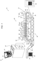
- Fig. 1 is a schematic side view of a digital printing system 10, in accordance with an embodiment of the present invention.
- system 10 comprises a rolling flexible blanket 44 that cycles through an ink supply subsystem, also referred to herein as an image forming station 60, multiple drying stations, an impression station 84 and a blanket treatment station 52.
- an ink supply subsystem also referred to herein as an image forming station 60
- multiple drying stations also referred to herein as an image forming station 60
- an impression station 84 multiple drying stations
- blanket treatment station 52 a blanket treatment station 52.
- the terms “blanket” and “intermediate transfer member (ITM)” are used interchangeably and refer to a flexible member comprising one or more layers used as an intermediate member configured to receive an ink image and to transfer the ink image to a target substrate, as will be described in detail below.
- image forming station 60 is configured to form a mirror ink image, also referred to herein as "an ink image” (not shown) or as an "image” for brevity, of a digital image 42 on an upper run of a surface of blanket 44. Subsequently the ink image is transferred to a target substrate, (e.g., a paper, a folding carton, a multilayered polymer, or any suitable flexible package in a form of sheets or continuous web) located under a lower run of blanket 44.
- a target substrate e.g., a paper, a folding carton, a multilayered polymer, or any suitable flexible package in a form of sheets or continuous web
- run refers to a length or segment of blanket 44 between any two given rollers over which blanket 44 is guided.
- blanket 44 may be adhered edge to edge to form a continuous blanket loop (not shown).
- An example of a method and a system for the installation of the seam is described in detail in U.S. Provisional Application 62/532,400 .
- image forming station 60 typically comprises multiple print bars 62, each mounted (e.g., using a slider) on a frame (not shown) positioned at a fixed height above the surface of the upper run of blanket 44.
- each print bar 62 comprises a strip of print heads as wide as the printing area on blanket 44 and comprises individually controllable print nozzles.
- image forming station 60 may comprise any suitable number of bars 62, each bar 62 may contain a printing fluid, such as an aqueous ink of a different color.
- the ink typically has visible colors, such as but not limited to cyan, magenta, red, green, blue, yellow, black and white.
- image forming station 60 comprises seven print bars 62, but may comprise, for example, four print bars 62 having any selected colors such as cyan, magenta, yellow and black.
- the print heads are configured to jet ink droplets of the different colors onto the surface of blanket 44 so as to form the ink image (not shown) on the outer surface of blanket 44.
- different print bars 62 are spaced from one another along the movement axis, also referred to herein as a moving direction of blanket 44, represented by an arrow 94.
- a moving direction of blanket 44 also referred to herein as a moving direction of blanket 44.
- system 10 comprises dryers 66.
- each dryer 66 comprises an infrared-based (IR-based) heater, which is configured to dry some of the liquid carrier of the ink applied to the ITM surface, by increasing the temperature of blanket 44 and evaporating at least part of the liquid carrier of the ink.
- IR-based infrared-based
- dryers 66 are positioned in between print bars 62, and are configured to partially dry the ink droplets deposited on the surface of blanket 44.
- some sections of the ink image printed on blanket 44 may comprise a mixture of two or more colors of ink, so as to produce a different color.
- a mixture of cyan and magenta may result in a blue color.
- the red print bar may be positioned, along the moving direction of blanket 44 (represented by arrow 94), before the yellow print bar.
- a processor 20 of system 10 is configured to control one or more of dryers 66 located between the red and yellow print bars to partially dry the red ink.
- the partial drying of the red ink enables the mixing of the red and yellow inks, so as to form the orange color at the given position on the surface of blanket 44.
- blanket 44 has a specification of operational temperatures, for example, blanket 44 is configured to operate at temperatures below about 140°C or 150°C in order to prevent damage, such as distortion, to the structure of blanket 44.
- system 10 further comprises a temperature control assembly 121, (described in detail in Figs. 3 and 4 below), which is configured to supply any suitable gas to the surface of blanket 44, so as reduce the heat applied by the IR-based heaters, and thereby, to maintain the temperature of blanket 44 below about 140°C or 150°C or any other certain temperature.
- the gas may comprise pressurized air and temperature control assembly 121 may comprise a central air blower, configured to supply the pressurized air, via outlet valves, to dryers 66.
- dryer 66 comprises a combination of the aforementioned IR-based heater, for heating blanket 44, and air-flow channels for cooling blanket 44.
- the pressurized air may be used for cooling sections of dryer 66 that are heated by the IR-based heater.
- temperature control assembly 121 further comprises an exhaust, which is configured to pump the pressurized air used for cooling blanket 44 and dryer 66, so as to reduce or prevent condensation of ink by products at the surface of the print heads.
- drying unit may refer to an apparatus comprising a combination of an IR-based heater for heating blanket 44, and air-flow channels for cooling blanket 44.
- each dryer 66 may comprise a single drying unit.
- temperature control assembly 121 and of dryers 66 are depicted in detail in Figs. 3 and 4 below.
- this heating between the print bars may assist, for example, in reducing or eliminating condensation at the surface of the print heads and/or in handling satellites (e.g., residues or small droplets distributed around the main ink droplet), and/or in preventing blockage of the inkjet nozzles of the print heads, and/or in preventing the droplets of different color inks on blanket 44 from undesirably merging into one another.
- satellites e.g., residues or small droplets distributed around the main ink droplet
- system 10 comprises a drying station, referred to herein as a main dryer 64, which is configured to dry the ink image applied to the surface of blanket 44 by image forming station 60. Note that at each of dryers 66 is configured to dry ink droplets during the formation of the ink image.
- main dryer 64 comprises an array of ten drying units arranged in a row parallel to the moving direction of blanket 44.
- main dryer 64 is configured to receive blanket 44 at any suitable temperature, for example, between about 60°C and about 100°C and to increase the temperature of blanket 44 to any suitable temperature, for example, between about 110°C and about 150°C after being heated by main dryer 64.
- blanket 44 When passing through main dryer 64, blanket 44 (having the ink image thereon) is exposed to the IR radiation and may reach the aforementioned temperature (e.g., about 140°C).
- main dryer 64 is configured to dry the ink more thoroughly by evaporating most or all of the liquid carrier, and leaving on the surface of blanket 44 only a layer of resin and coloring agent, which is heated to the point of being rendered tacky ink film.
- main dryer 64 The structure and functionality of main dryer 64 will be depicted in detail, for example, in Fig. 4 below.
- system 10 comprises a vertical dryer 96 having an assembly for pumping (e.g., using vacuum) gas residues evaporated from the surface of blanket 44.
- vertical dryer 96 may comprise an air knife, which is configured to blow pressurized air (or any other suitable gas) on the surface of blanket 44, so as to reduce the temperature of blanket 44 and/or to remove the aforementioned gas residues from the surface of blanket 44.
- processor 20 is configured to control, in vertical dryer 96, the vacuum level and/or the air pressure, so as to obtain the desired cleanliness and/or temperature on the surface of blanket 44. Note that the cleanliness of the surface of blanket 44 is particularly important before the ink image printed on blanket 44 enters impression station 84 as will be described in detail herein.
- system 10 comprises a blanket pre-heater 98, which comprises an IR radiation source (not shown) having an exemplary length of about 1120 mm or any other suitable length.
- the IR heat source may comprise any suitable product complying with the specified power density (which is application-dependent) supplied, for example by Heraeus (Hanau, Germany), or by Helios (Novazzano, Switzerland).
- blanket pre-heater 98 is configured for uniformly heating blanket 44 to an exemplary temperature of about 75°C, so as to prepare blanket 44 for the printing process (described above) of the ink image, carried out by image forming station 60.
- blanket module 70 such as rollers 78, typically remain at room temperature (e.g., 25°C) or any other suitable temperature, typically lower than the temperature required for drying the ink jetted on the surface of blanket 44. As a result, blanket 44 is cooling when rolling along these elements of blanket module 70.
- processor 20 controls vertical dryer 96 for completion (if needed) of the ink drying before blanket 44 enters impression station 84, and further controls blanket pre-heater 98 for maintaining the specified temperature (e.g., about 75°C) of blanket 44 before entering image forming station 60.
- blanket pre-heater 98 may comprise an air blower (not shown) configured to supply and direct hot air for heating the surface of blanket 44.
- air blower not shown
- blanket 44 may be heated to about 75°C within a few (e.g., five) minutes using IR radiation, or within about half hour using the hot air.
- system 10 comprises a blanket module 70 comprising blanket 44.
- blanket module 70 comprises one or more rollers 78, wherein at least one of rollers 78 may comprise an encoder (not shown), which is configured to record the position of blanket 44, so as to control the position of a section of blanket 44 relative to a respective print bar 62.
- the encoder of roller 78 typically comprises a rotary encoder configured to produce rotary-based position signals indicative of an angular displacement of the respective roller. Note that in the context of the present invention and in the claims, the terms “indicative of” and “indication” are used interchangeably.
- blanket module 70 may comprise any other suitable apparatus for sensing and/or tracking the position of one or more reference points of blanket 44.
- blanket 44 may comprise markers disposed on the blanket surface and/or engraved within the blanket.
- system 10 may comprise sensing assemblies, configured to sense the markers and to send, e.g., to processor 20, position signals indicative of the positions of respective markers of blanket 44.
- blanket 44 may comprise a fabric made from two or more sets of fibers interleaved with one another.
- the fabric has an opacity that varies in accordance with a periodic pattern of the interleaved fibers.
- system 10 may comprise an optical assembly (not shown) having a light source at one side of blanket 44, and a light detector at the other side of blanket 44.
- the optical assembly is configured to illuminate blanket 44 with light, to detect the light passing through the fabric, and to derive from the detected light one or more position signals indicative of one or more respective position reference points (e.g., fibers) in the periodic pattern of the fabric.
- processor 20 is configured to control the printing process and to monitor the condition of various elements of system 10, such as blanket 44.
- blanket 44 may comprise any suitable type of integrated encoder (not shown) for controlling the operation of various modules of system 10.
- integrated encoder is described in detail, for example, in U.S. Provisional Application 62/689,852 .
- blanket 44 is guided over rollers 78 and a powered tensioning roller, also referred to herein as a dancer assembly 74.
- Dancer assembly 74 is configured to control the length of slack in blanket 44 and its movement is schematically represented by a double sided arrow. Furthermore, any stretching of blanket 44 with aging would not affect the ink image placement performance of system 10 and would merely require the taking up of more slack by tensioning dancer assembly 74.
- dancer assembly 74 may be motorized.
- rollers 78 are described in further detail, for example, in U.S. Patent Application Publication 2017/0008272 and in the above-mentioned PCT International Publication WO 2013/132424 .
- dancer assembly 74 may comprise a pressurized-air based dancer assembly (not shown), comprising an air chamber and a light-weight roller fitted in the air chamber.
- the air chamber may comprise an inlet and an opening, which is sized and shaped to fit snugly over the roller.
- the pressurized-air based dancer assembly may comprise a controllable air blower (other than the aforementioned air blower of temperature control assembly 121), which is configured to supply pressurized air, via a given inlet, into the air chamber.
- the pressurized air applies a uniform pressure to the roller and moves the roller along a longitudinal axis of the air chamber.
- the roller may protrude from the air chamber through the opening, and applies a tension to blanket 44 while being rotated by blanket 44.
- the pressurized-air based dancer assembly is further described, for example, in U.S. provisional application 62/889,069 .
- system 10 may comprise one or more tension sensors (not shown) disposed at one or more positions along blanket 44.
- the tension sensors may be integrated in blanket 44 or may comprise sensors external to blanket 44 using any other suitable technique to acquire signals indicative of the mechanical tension applied to blanket 44.
- processor 20 and additional controllers of system 10 are configured to receive the signals produce by the tension sensors, so as to monitor the tension applied to blanket 44 and to control the operation of dancer assembly 74.
- blanket 44 passes between an impression cylinder 82 and a pressure cylinder 90, which is configured to carry a compressible blanket.
- system 10 comprises a control console 12, which is configured to control multiple modules of system 10, such as blanket module 70, image forming station 60 located above blanket module 70, and a substrate transport module 80, which is located below blanket module 70 and comprises one or more impression stations as will be described below.
- modules of system 10 such as blanket module 70, image forming station 60 located above blanket module 70, and a substrate transport module 80, which is located below blanket module 70 and comprises one or more impression stations as will be described below.
- console 12 comprises processor 20, typically a general-purpose computer, with suitable front end and interface circuits for interfacing with controllers of dancer assembly 74 and with a controller 54, via an electrical cable, referred to herein as a cable 57, and for receiving signals therefrom.
- processor 20 typically a general-purpose computer, with suitable front end and interface circuits for interfacing with controllers of dancer assembly 74 and with a controller 54, via an electrical cable, referred to herein as a cable 57, and for receiving signals therefrom.
- controller 54 which is schematically shown as a single device, may comprise one or more electronic modules mounted on system 10 at predefined locations. At least one of the electronic modules of controller 54 may comprise an electronic device, such as control circuitry or a processor (not shown), which is configured to control various modules and stations of system 10.
- processor 20 and the control circuitry may be programmed in software to carry out the functions that are used by the printing system, and store data for the software in a memory 22.
- the software may be downloaded to processor 20 and to the control circuitry in electronic form, over a network, for example, or it may be provided on non-transitory tangible media, such as optical, magnetic or electronic memory media.
- console 12 comprises a display 34, which is configured to display data and images received from processor 20, or inputs inserted by a user (not shown) using input devices 40.
- console 12 may have any other suitable configuration, for example, an alternative configuration of console 12 and display 34 is described in detail in U.S. Patent 9,229,664 .
- processor 20 is configured to display on display 34, a digital image 42 comprising one or more segments (not shown) of image 42 and/or various types of test patterns that may be stored in memory 22.
- blanket treatment station 52 is configured to treat the blanket by, for example, cooling the blanket and/or applying a treatment fluid to the outer surface of blanket 44, and/or cleaning the outer surface of blanket 44.
- the temperature of blanket 44 can be reduced to a desired value of temperature.
- the treatment may be carried out by passing blanket 44 over one or more rollers or blades configured for applying cooling and/or cleaning and/or treatment fluid on the outer surface of the blanket.
- blanket treatment station 52 may be positioned adjacent to impression station 84. Additionally or alternatively, the blanket treatment station may comprise one or more bars (not shown), adjacent to print bars 62. In this configuration, the treatment fluid may be applied to blanket 44 by jetting.
- system 10 comprises one or more temperature sensors 92, in the present example, sensors 92A, 92B, 92C and 92D, disposed at one or more respective given locations relative to blanket 44 and configured to produce signals indicative of the surface temperature of blanket 44, also referred to herein as "temperature signals.”
- At least one of temperature sensors 92A-92D may comprise an IR-based temperature sensor, which is configured to sense the temperature based IR radiation emitted from the surface of blanket 44. In other embodiments, at least one of temperature sensors 92A-92D may comprise any other suitable type of temperature sensor.
- system 10 comprises: (i) a first temperature sensor 92A, disposed in close proximity to a blanket-tension drive roller, referred to herein as a roller 78A, (ii) a second temperature sensor 92B, disposed between a first print bar 62 and a first dryer, referred to herein as a pre-heater 66A, (iii) a third temperature sensor 92C, disposed between the right-most print bar 62 (in the moving direction) and main dryer 64, and (iv) a fourth temperature sensor 92D, disposed in close proximity to a blanket-control drive roller, referred to herein as a roller 78B.
- temperature sensor 92A which is disposed between blanket pre-heater 98 and image forming station 60, is configured to sense the temperature of blanket 44 before entering image forming station 60.
- temperature sensor 92B is positioned (in the moving direction shown by arrow 94) after pre-heater 66A, so as to measure the temperature of blanket 44 before entering the first print bar.
- controller 54 and/or processor 20 are configured to receive temperature signals from one or more of the temperature sensors described above, and to control the printing process based on the received temperature signals, as will be described in detail below.
- the temperature signal from temperature sensor 92B may be sufficient for controlling starting a new cycle of a printing process carried out by image forming station 60, so that temperature sensor 92A may be redundant, and therefore may be removed from the configuration of system 10.
- the temperature of blanket 44 is important for the quality of the printing process carried out by image forming station 60.
- the temperature of blanket 44 is set to a predefined temperature (e.g., about 70°C) so as to: (i) dry the ink droplets of a first color applied to the ITM by the first print bar, and (ii) regain the blanket temperature (which is cooled by the ink droplets having a typical temperature of about 30°C or 35°C) to the predefined temperature of about 70°C.
- a predefined temperature e.g., about 70°C
- a controlled amount of vapors of the first printing fluid typically evaporate from the blanket surface without adhering to nozzles of any print bars 62.
- the temperature of the first ink is control by the blanket temperature, so that, after applying the droplets of the second color, the first and second colors of ink droplets are mixed with one another so as to form the requested color on the surface of a release layer of blanket 44.
- temperature sensors 92A-92D are positioned after every event or sub-step of the printing process, which affects or may affect the temperature of blanket 44.
- processor 20 and/or controller 54 is configured to control a power source (not shown) to adjust the power density applied to one or more infrared sources (shown for example in Fig. 3 below) of the respective heater.
- processor 20 is configured to adjust the power density applied to the dryers using a closed-loop methodology, both in feed-back and feed-forward modes.
- feed-back refers to adjusting the power density in a given dryer based on temperature measured after using the given dryer, so as to obtain the required temperature in a subsequent section of the blanket.
- feed-forward refers to adjusting the power density based on temperature measured before using the dryer, so as to compensate for any deviation from the required temperature.
- processor 20 is configured to control the power density applied to the one or more IR source(s) of pre-heaters 98 and 66A, based on the temperature signal received from temperature sensor 92A, using, respectively, feed-back and feed-forward modes of the closed loop.
- processor 20 controls the power source to: (i) increase the power density applied to pre-heater 66A for obtaining the 70°C in the first section of blanket 44 (using the feed-forward mode), and (ii) increase the power density applied to pre-heater 98 for obtaining the 70°C in a second section of blanket 44, which follows the first section (using the feed-back mode).
- processor 20 receives the temperature signal from temperature sensor 92B. In case the temperature is about 70°C, processor 20 allows the first print bar of image forming station 60, to apply droplets of the first ink to blanket 44. But in case the temperature measured by temperature sensor 92B is substantially different from about 70°C (e.g., about 50°C), processor 20 prevents the print bars of image forming station 60 from applying ink droplets to blanket 44, and controls the power source for adjusting the blanket temperature to the predefined temperature of about 70°C. Only after obtaining the 70°C, processor 20 controls image forming station 60 to resume the printing process using print bars 62, as described above.
- processor 20 controls image forming station 60 to resume the printing process using print bars 62, as described above.
- processor 20 is configured to: (i) control the power density applied to main dryer 64, based on temperature signals received from temperature sensor 92C, and (ii) control the power density applied to vertical dryer 96, based on temperature signals received from temperature sensor 92D. Additionally or alternatively, processor 20 may use the signals received from temperature sensor 92D for adjusting the power density supplied to main dryer 64.
- processor 20 in response to receiving the temperature signals, is configured to control the blanket temperature by adjusting the flow rate of the pressurized air in the air-flow channels shown and described in detail in Figs. 3 and 4 below.
- processor 20 is configured to use the feed-forward and feed-back methodology to carry out the closed-loop control on relevant air blowers of system 10. For example, when the measured temperature exceeds the required temperature of blanket 44, processor 20 is configured to control the air blowers to increase the flow of the pressurized air applied to blanket 44. Similarly, when the measured temperature is below the required temperature of blanket 44, processor 20 is configured to control the air blowers to reduce the flow of the pressurized air applied to blanket 44.
- processor 20 is configured to control both the intensity of IR radiation (by adjusting the power density supply) and the flow of the pressurized air, at the same time, so as to control the temperature of blanket 44. For example, in response to receiving from temperature sensor 92D, a signal indicating that the temperature of blanket 44 is substantially different than about 140°C, processor 20 may control at least one of main dryer 64 and vertical dryer 96, to adjust the intensity of IR radiation and/or the flow of the pressurized air so as to obtain the specified temperature of about 140°C on blanket 44.
- processor 20 is further configured to control the operation of other assemblies and stations of system 10, such as but not limited to blanket treatment station 52.
- other assemblies and stations of system 10 such as but not limited to blanket treatment station 52. Examples of such treatment stations are described, for example, in PCT International Publications WO 2013/132424 and WO 2017/208152 .
- treatment fluid may be applied to blanket 44, by jetting, prior to the ink jetting at the image forming station.
- station 52 is mounted between impression station 84 and image forming station 60, yet, station 52 may be mounted adjacent to blanket 44 at any other or additional one or more suitable locations between impression station 84 and image forming station 60. As described above, station 52 may additionally or alternatively comprise on a bar adjacent to image forming station 60.
- impression cylinder 82 impresses the ink image onto the target flexible substrate, such as an individual sheet 50, conveyed by substrate transport module 80 from an input stack 86 to an output stack 88 via impression cylinder 82.
- the lower run of blanket 44 selectively interacts at impression station 84 with impression cylinder 82 to impress the image pattern onto the target flexible substrate compressed between blanket 44 and impression cylinder 82 by the action of pressure of pressure cylinder 90.
- impression station 84 In the case of a simplex printer (i.e., printing on one side of sheet 50) shown in Fig. 1 , only one impression station 84 is needed.
- module 80 may comprise two or more impression cylinders so as to permit one or more duplex printing.
- the configuration of two impression cylinders also enables conducting single sided prints at twice the speed of printing double sided prints.
- mixed lots of single and double sided prints can also be printed.
- a different configuration of module 80 may be used for printing on a continuous web substrate.
- Detailed descriptions and various configurations of duplex printing systems and of systems for printing on continuous web substrates are provided, for example, in U.S. patents 9,914,316 and 9,186,884 , in PCT International Publication WO 2013/132424 , in U.S. Patent Application Publication 2015/0054865 , and in U.S. Provisional Application 62/596,926 .
- sheets 50 or continuous web substrate are carried by module 80 from input stack 86 and pass through the nip (not shown) located between impression cylinder 82 and pressure cylinder 90.
- the surface of blanket 44 carrying the ink image is pressed firmly, e.g., by compressible blanket (not shown), of pressure cylinder 90 against sheet 50 (or other suitable substrate) so that the ink image is impressed onto the surface of sheet 50 and separated neatly from the surface of blanket 44.
- sheet 50 is transported to output stack 88.
- rollers 78 are positioned at the upper run of blanket 44 and are configured to maintain blanket 44 taut when passing adjacent to image forming station 60. Furthermore, it is particularly important to control the speed of blanket 44 below image forming station 60 so as to obtain accurate jetting and deposition of the ink droplets, thereby placement of the ink image, by forming station 60, on the surface of blanket 44.
- impression cylinder 82 is periodically engaged to and disengaged from blanket 44 to transfer the ink images from moving blanket 44 to the target substrate passing between blanket 44 and impression cylinder 82.
- system 10 is configured to apply torque to blanket 44 using the aforementioned rollers and dancer assemblies, so as to maintain the upper run taut and to substantially isolate the upper run of blanket 44 from being affected by mechanical vibrations occurring in the lower run.
- system 10 comprises an image quality control station 55, also referred to herein as an automatic quality management (AQM) system, which serves as a closed loop inspection system integrated in system 10.
- station 55 may be positioned adjacent to impression cylinder 82, as shown in Fig. 1 , or at any other suitable location in system 10.
- station 55 comprises a camera (not shown), which is configured to acquire one or more digital images of the aforementioned ink image printed on sheet 50.
- the camera may comprises any suitable image sensor, such as a Contact Image Sensor (CIS) or a Complementary metal oxide semiconductor (CMOS) image sensor, and a scanner comprising a slit having a width of about one meter or any other suitable width.
- CIS Contact Image Sensor
- CMOS Complementary metal oxide semiconductor
- the terms “about” or “approximately” for any numerical values or ranges indicate a suitable dimensional tolerance that allows the part or collection of components to function for its intended purpose as described herein.
- “about” or “approximately” may refer to the range of values ⁇ 20% of the recited value, e.g. "about 90%” may refer to the range of values from 72% to 100%.
- station 55 may comprise a spectrophotometer (not shown) configured to monitor the quality of the ink printed on sheet 50.
- the digital images acquired by station 55 are transmitted to a processor, such as processor 20 or any other processor of station 55, which is configured to assess the quality of the respective printed images. Based on the assessment and signals received from controller 54, processor 20 is configured to control the operation of the modules and stations of system 10.
- processor refers to any processing unit, such as processor 20 or any other processor or controller connected to or integrated with station 55, which is configured to process signals received from the camera and/or the spectrophotometer of station 55. Note that the signal processing operations, control-related instructions, and other computational operations described herein may be carried out by a single processor, or shared between multiple processors of one or more respective computers.
- station 55 is configured to inspect the quality of the printed images and test pattern so as to monitor various attributes, such as but not limited to full image registration with sheet 50, color-to-color (C2C) registration, printed geometry, image uniformity, profile and linearity of colors, and functionality of the print nozzles.
- processor 20 is configured to automatically detect geometrical distortions or other errors in one or more of the aforementioned attributes. For example, processor 20 is configured to compare between a design version (also referred to herein as a "master” or a "source image” of a given digital image and a digital image of the printed version of the given image, which is acquired by the camera.
- processor 20 may apply any suitable type image processing software, e.g., to a test pattern, for detecting distortions indicative of the aforementioned errors.
- processor 20 is configured to analyze the detected distortion in order to apply a corrective action to the malfunctioning module, and/or to feed instructions to another module or station of system 10, so as to compensate for the detected distortion.
- processor 20 is configured to detect, based on the signals acquired by station 55, various types of defects: (i) in the substrate (e.g., blanket 44 and/or sheet 50), such as a scratch, a pin hole, and a broken edge, and (ii) printing-related defects, such as irregular color spots, satellites, and splashes.
- substrate e.g., blanket 44 and/or sheet 50
- printing-related defects such as irregular color spots, satellites, and splashes.
- processor 20 is configured to detect these defects by comparing between a section of the printed and a respective reference section of the original design, also referred to herein as a master. Processor 20 is further configured to classify the defects, and, based on the classification and predefined criteria, to reject sheets 50 having defects that are not within the specified predefined criteria.
- the processor of station 55 is configured to decide whether to stop the operation of system 10, for example, in case the defect density is above a specified threshold.
- the processor of station 55 is further configured to initiate a corrective action in one or more of the modules and stations of system 10, as described above.
- the corrective action may be carried out on-the-fly (while system 10 continue the printing process), or offline, by stopping the printing operation and fixing the problem in a respective modules and/or station of system 10.
- any other processor or controller of system 10 e.g., processor 20 or controller 54
- processor 20 is configured to receive, e.g., from station 55, signals indicative of additional types of defects and problems in the printing process of system 10. Based on these signals processor 20 is configured to automatically estimate the level of pattern placement accuracy and additional types of defects not mentioned above.
- any other suitable method for examining the pattern printed on sheets 50 can also be used, for example, using an external (e.g., offline) inspection system, or any type of measurements jig and/or scanner.
- processor 20 based on information received from the external inspection system, processor 20 is configured to initiate any suitable corrective action and/or to stop the operation of system 10.
- system 10 is simplified and provided purely by way of example for the sake of clarifying the present invention.
- the components, modules and stations described in printing system 10 hereinabove and additional components and configurations are described in detail, for example, in U.S. Patents 9,327,496 and 9,186,884 , in PCT International Publications WO 2013/132438 , WO 2013/132424 and WO 2017/208152 , in U.S. Patent Application Publications 2015/0118503 and 2017/0008272 .
- system 10 is shown by way of example, in order to illustrate certain problems that are addressed by embodiments of the present invention and to demonstrate the application of these embodiments in enhancing the performance of such systems.
- Embodiments of the present invention are by no means limited to this specific sort of example system, and the principles described herein may similarly be applied to any other sorts of printing systems.
- dryer 66 and/or blanket pre-heater 98 may comprise more than one source of IR radiation.
- main dryer 64 may comprise any other suitable number of drying units, or any other suitable type of ink-drying apparatus.
- At least one of the dryers may comprise a radiation sources configured to emit radiation other than IR.
- a radiation sources configured to emit radiation other than IR.
- IR near IR
- visible light visible light
- UV ultraviolet
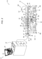
- Fig. 2 is a schematic side view of a digital printing system 110, in accordance with an embodiment of the present invention.
- system 110 comprises blanket 44 that cycles through an image forming station 160, and through drying station 64, vertical dryer 96, blanket pre-heater 98, and blanket treatment station 52 described in Fig. 1 above.
- system 110 is configured to transfer the ink images from moving blanket 44 to a continuous flexible web substrate, referred to herein as web 51, which is the target substrate of system 110.
- system 110 comprises a substrate transfer module 100, which is configured to convey web 51 from a pre-print buffer unit 186, via one or more impression stations 85 for receiving the ink image from blanket 44, to a post-print buffer unit 188.
- Each impression station 85 may have any configuration suitable for transferring the ink image from blanket 44 to web 51.
- the lower run of blanket 44 may selectively interact, at impression station 85, with an impression cylinder 192 to impress the image pattern onto web 51 compressed between blanket 44 and impression cylinder 192 by the action of pressure of a pressure cylinder 190.
- system 110 may comprise, for example, two impression stations 85.
- substrate transfer module 100 may have any suitable configuration for conveying web 51.
- One example implementation is described in detail in U.S. Provisional Application 62/784,576.
- web 51 comprises one or more layers of any suitable material, such as an aluminum foil, a paper, polyester (PE), polyethylene terephthalate (PET), biaxially oriented polypropylene (BOPP), oriented polyamide (OPA), biaxially oriented polyamide (BOPA), other types of oriented polypropylene (OPP), a shrinked film also referred to herein as a polymer plastic film, or any other materials suitable for flexible packaging in a form of continuous web, or any suitable combination thereof, e.g., in a multilayered structure.
- Web 51 may be used in various applications, such as but not limited to food packaging, plastic bags and tubes, labels, decoration and flooring.
- image forming station 160 typically comprises multiple print bars 62, each mounted (e.g., using a slider) on a frame (not shown) positioned at a fixed height above the surface of the upper run of blanket 44.
- each print bar 62 comprises a plurality of print heads arranged so as to cover the width of the printing area on blanket 44 and comprises individually controllable print nozzles, as also described in Fig. 1 above.
- image forming station 160 may comprise any suitable number of print bars 62, each print bar 62 may contain the aforementioned printing fluid, such as the aqueous ink.
- the ink typically has visible colors, such as but not limited to cyan, magenta, red, green, blue, yellow, black and white.
- image forming station 160 comprises a white print bar 61 and four print bars 62 having any selected colors such as cyan, magenta, yellow and black.
- white ink is applied to the surface of web 51 before all other colors, and in some cases it is important that in at least some sections of web 51 the white color will not be mixed with the other colors of ink.
- system 110 comprises a white-ink drying station, referred to herein as a white dryer 97, which is configured to dry the white ink applied to the surface of blanket 44 by image forming station 160.
- white dryer 97 may comprise five drying units, each of which comprising a combination of the aforementioned IR-based heater for heating blanket 44, and one or more air-flow channels for cooling blanket 44.
- white dryer 97 may comprise any other configuration suitable for drying the white ink, for example, white dryer 97 may comprise any other number of drying units, or may comprise any other suitable dryer apparatus using any other suitable drying technique.
- white dryer 97 is controlled by processor 20 and/or by controller 54, and is configured to dry the white ink applied to the surface of blanket 44 by white print bar 61.
- processor 20 and/or controller 54 are configured to control white dryer 97 for partially or fully drying the white ink applied to the surface of blanket 44.
- white dryer 97 replaces one dryer 66 used for drying any color of ink other than white.
- system 110 does not have a print bar between white dryer 97 and the first dryer 66, but in other embodiments, system 110 may have any suitable printing components (e.g., a print bar) or sensing components (e.g., a temperature sensor or any other type of sensor), between white dryer 97 and the first dryer 66.
- system 110 may comprise any other suitable type of dryer for drying, or partially drying, any particular color of ink other than white.
- the white ink may be applied to the surface of web 51 after all other colors.
- the white ink may be applied to the surface of web 51, using a subsystem external to or integrated with system 110.
- the white ink is applied to the surface of web 51 before or after applying the other colors to the surface of blanket 44, using image forming station 160, and particularly, before or after applying the other colors to the surface of web 51 in impression station 85.
- temperature sensor 92B is disposed between the aforementioned first dryer 66 and print bar 62, so as to confirm the surface temperature of blanket 44 before applying the ink having a color other than white using print bar 62. Moreover, temperature sensor 92B is disposed between the last print bar of image forming station 160, and main dryer 64. Note that temperature sensors 92A, 92C and 92D are disposed at the same positions in both system 110 and system 10 of Fig. 1 above.
- Temperature sensor 92B is disposed, along the path of blanket 44, after the white-color printing and drying (in the present example, after print bar 61 and dryer 97) and before the first print bar 62 of the colors other than white (e.g., cyan, magenta, yellow, black or any other color).
- the white-color printing and drying in the present example, after print bar 61 and dryer 97
- the first print bar 62 of the colors other than white e.g., cyan, magenta, yellow, black or any other color.
- temperature sensors 92B, 92C and 92D are disposed after processing sub-steps that typically affect or may affect the temperature of blanket 44, as also described in Fig. 1 above.
- system 110 may comprise a drying station, referred to herein as a bottom dryer 75, which is configured to emit infrared light or any other suitable frequency, or range of frequencies, of light for drying the ink image formed on blanket 44 using the technique described above.
- bottom dryer 75 may comprise five drying units, each of which comprising a combination of the aforementioned IR-based heater for heating blanket 44, and one or more air-flow channels for cooling blanket 44.
- system 110 comprises a temperature sensor 92E, disposed between bottom dryer 75 and impression station 85, typically in closer proximity to bottom dryer 75.
- processor 20 (and/or controller 54) is configured to control the power source (not shown) described in Fig. 1 above, to adjust the power density applied to one or more infrared sources (shown in Figs. 3 and 4 below) of the respective heater and/or dryer, so as to retain the predefined temperature of blanket 44 along the respective section of system 110.
- processor 20 (and/or controller 54) is configured to perform a closed-loop control on the temperature profile of blanket 44 along the respective sections of system 110.
- the control is carried out based on the temperature signals received from at least one of temperature sensors 92A-92E, and based on the temperature signals, processor 20 controls the power density applied to the IR power sources of the respective IR-based heaters (e.g., one or more of heater 98 and dryers 97, 66, 64, 96 and 75).
- bottom dryer 75 may comprise any other suitable configuration adapted for drying the ink at the lower run of blanket 44, before the blanket enters impression station 85.
- processor 20 and/or controller 54 are configured to control each dryer of system 10 (shown in Fig. 1 ) and system 110 (shown in Fig. 1 ) selectively.
- the control may be carried out based on various conditions of the particular digital printing application. For example, based on the type, order and surface coverage level of colors applied to the surface of blanket 44, and based on the type of blanket 44 and target substrate (e.g., sheet 50 or web 51).
- target substrate e.g., sheet 50 or web 51.
- coverage level refers to the amount of color applied to the surface of blanket 44.
- a 250% coverage level refers to two and half ink layers applied to a predefined section (or the entire area) of the ink image specified for being printed on blanket 44 and subsequently, for being transferred to the target substrate. Note that the two and half ink layers may comprise three or more of the aforementioned colors of ink as described above. It will be understood that larger coverage level typically requires larger flux of IR irradiation, and therefore, higher flow of air for cooling blanket 44.
- the ink drying process may be carried out in an open loop, e.g., without controlling at least one of (a) the intensity of the IR radiation and (b) the pressurized-air flow rate by temperature control assembly 121.
- a recipe parameter may comprise the coverage level of the ink image, and processor 20 and/or controller 54 may preset one or more of (a) the intensity of the IR radiation and (b) the pressurized-air flow rate by temperature control assembly 121, so as to dry the ink and maintain the temperature of blanket 44 below the specified temperature (e.g., about 140°C or about 150°C).
- system 110 is shown by way of example, in order to illustrate certain problems that are addressed by embodiments of the present invention and to demonstrate the application of these embodiments in enhancing the performance of such systems.
- Embodiments of the present invention are by no means limited to this specific sort of example system, and the principles described herein may similarly be applied to any other sorts of printing systems.
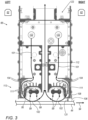
- Fig. 3 is a schematic side view of dryer 66 for drying the ink applied by print bars 62, in accordance with an embodiment of the present invention.
- dryer 66 comprises a single drying unit, such as the drying unit briefly described in Fig. 1 above and further described in detail herein.
- dryer 66 comprises one or more openings to an air inlet channel (AIC) 122, having an air blower and configured to supply pressurized air 101 (or any other type of suitable gas) into dryer 66.
- AIC air inlet channel
- dryer 66 further comprises one or more openings to an air outlet channel (AOC) 123, having an air extraction apparatus (e.g., a suitable type of vacuum or negative pressure pump) configured to draw pressurized air 101 after cooling at least blanket 44, as will be described herein.
- AOC air outlet channel
- temperature control assembly refers to at least one of AIC 122 and AOC 123 or a combination thereof, and is configured to direct pressurized air 101 (or any other suitable type of gas) to an outer surface 106 of blanket 44 so as to reduce the temperature of blanket 44 below the specified temperature (e.g., about 140°C or about 150°C), as will be described herein.
- dryers 66 are typically positioned within image forming station 60, and main dryer 64 is positioned between image forming station 60 and impression station 84 such that the drying process of the ink image applied to blanket 44 is carried out before the ink image is transferred to the target substrate (e.g., sheet 50) in impression station 84.
- temperature control assembly 121 is configured to supply pressurized air 101, e.g., via pipes or tubes (not shown), to dryers 66 and main dryer 64, so as to control the temperature of blanket 44 within the specified temperature range described above.
- system 10 may comprise multiple AICs 122 and/or AOCs 123, e.g., a first set of AIC 122 and AOC 123 for dryers 66 and a second set of AIC 122 and AOC 123 for main dryer 64.
- system 10 may comprise any other suitable configuration of AICs 122 and/or AOCs 123 controlled by processor 20 and/or by local controllers that are synchronized with and/or controlled by processor 20.
- dryer 66 comprises one or more IR-based heaters, in the present example an illumination assembly 113 having IR radiation sources, referred to herein as sources 111 for brevity.
- dryer 66 comprises two pairs of sources 111 arranged in two respective cavities of dryer 66.
- Each source 111 is configured to direct a beam 99 of IR radiation to blanket 44.
- each source 111 is configured to emit a power density between about 30 w/cm and about 300 w/cm toward surface 106 of blanket 44.
- dryer 66 may comprise any other suitable number of sources 111 (or any other suitable type of one or more light sources configured to emit IR or other suitable one or more wavelengths of light) having any suitable geometry and arranged in any suitable configuration.
- dryer 66 may comprise one or more reflectors 108, coupled between sources 111 and the cavity of dryer 66.
- Reflectors 108 are configured to reflect beams 99 emitted from sources 111 toward blanket 44 so as to improve the efficiency and speed of the IR-based drying process, and for reducing the amount of IR radiation (and therefore excess heating) applied to dryer 66 by beams 99.
- each reflector 108 may reflect about 90% of beams 99 toward blanket 44 and may absorb the remaining 10%, which may increase the temperature at the cavities of dryer 66.
- dryer 66 comprises a heat transfer assembly (HTA) 104, which comprises heat conducting materials (e.g., copper, aluminum or other metallic or non-metallic materials) arranged around reflectors 108 as heat-conducting ribs and traces.
- HTA 104 IS configured to dissipate the excess heat away from the respective cavities of dryer 66.
- pressurized air 101 enters dryer 66, via AIC 122, at an exemplary temperature of about 30°C or at any other suitable temperature between about 5°C and about 100°C. Subsequently, pressurized air 101 flows through an internal channel of dryer 66 for transporting heat (e.g., by heat convection) away from HTA 104, and then directed, via an opening 95 of dryer 66, toward a position 102 on surface 106. Pressurized air 101 flow on surface 106 for transferring the heat from blanket 44, and subsequently, AOC 123 draws pressurized air 101 away from surface 106, via an air outlet passage 112 of dryer 66, for maintaining the temperature of blanket 44 below the specified temperature described above.
- heat e.g., by heat convection
- dryer 66 may be located adjacent to a print bar 62, and typically between two adjacent print bars 62.
- dryer 66 is configured to draw pressurized air 101 via air outlet passage 112, so that pressurized air 101 will not make physical contact with any of print bars 62.
- pressurized air 101 comprises vapors of the ink ingredients that may interfere with the printing process. For example, such vapors may partially or fully block nozzles of print bars 62, which may reduce the quality of the printed image (e.g., missing ink in case of a fully-blocked nozzle, or defects comprising clusters of dried ink in case of partially-blocked nozzle).
- the structure of dryer 66 prevents mixture of pressurized air 101 incoming from AIC 122 with pressurized air 101 flowing through opening 95 into surface 106. As described above, after flowing through opening 95, pressurized air 101 is forced to flow via air outlet passage 112, into AOC 123. In other words, the outflowing air that may contain residues of ink, and the incoming air for cooling surface 106 are never mixed with one another within dryer 66.
- beam 99 is directed to position 102 based on the position of sources 111 within the cavity of dryer 66.
- dryer 66 is designed such that pressurized air 101 is directed to position 102 for cooling blanket 44.
- each drying unit of dryer 66 comprises two sets, of IR-based heating and pressurized-air-based cooling, having air outlet passage 112 therebetween. In this configuration pressurized air 101 inflows toward blanket 44 from the sides of dryer 66, and outflows away from blanket 44 through air outlet passage 112 located at the center of dryer 66, so as to prevent contact between pressurized air 101 and print bars 62.
- a distance 131 which is the distance between dryer 66 and surface 106 may be used for controlling the amount of the IR-based heating and air-based cooling.
- smaller distance 131 accelerates the heating rate of blanket 44.
- blanket 44 will reach the specified temperature (e.g., about 140°C or about 150°C) faster, resulting in faster drying of the ink on the surface of blanket 44.
- distance 131 may be predetermined, e.g., when mounting dryer 66 on the frame of system 10 and/or system 110. In other embodiments, distance 131 may be controlled, e.g., by using any suitable mount for moving dryer 66 relative to blanket 44.
- processor 20 may control the intensity and uniformity of the power density applied, by source 111, to predefined sections of blanket 44. For example, larger distance 131 may result in smaller power density applied to a given section of blanket 44, but may improve the heating uniformity within the given section and in close proximity thereto. Similarly, the proximity between blanket 44 and dryer 66 may affect the level of cooling by dryer 66. For example, larger distance 131 reduces the cooling effectivity of the blanket surface by pressurized air 101.
- dryer 66 and the blanket are designed such that beam 99 is configured to heat blanket 44, and the increased temperature induces evaporation of the liquid carried of the ink so as to dry or partially dry the ink on surface 106. Note that beam 99 is not directed to the ink for the evaporation, but is directed to blanket 44 for increasing the temperature of the blanket. Similarly, pressurized air 101 is directed to blanket 44, by AIC 122, and extracted from blanket by AOC 123, so as to reduce the temperature thereof.
- drying unit of dryer 66 is provided by way of example, in order to illustrate certain problems, such as partially drying the ink image applied to blanket 44 and cooling the blanket, which are addressed by embodiments of the present invention and to demonstrate the application of these embodiments in enhancing the performance of digital printing systems such as systems 10 and 110 described above.
- Embodiments of the present invention are by no means limited to this specific configuration and sort of example drying unit, and the principles described herein may similarly be applied to any other sorts of drying units in digital printing systems or any other type of printing systems.
- pressurized air 101 may be used solely for reducing the temperature of blanket 44, whereas a separate (e.g., dedicated) cooling apparatus may be used for cooling HTA 104.
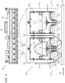
- Fig. 4 is a schematic side view of main dryer 64, in accordance with an embodiment of the present invention.
- main dryer 64 comprises multiple drying units 222, and an air outlet passage 130 between a respective pair of neighboring drying units 222.
- each drying unit 222 is positioned at a distance 132 from surface 106 of blanket 44.
- distance 132 may differ from distance 131 and may be controllable, e.g., using a mount as described in Fig. 3 above. Alternatively, distance 132 may be predetermined based on the distance between the frame of image forming station and the position of blanket 44.
- each drying unit 222 has two cavities, each of which having a pair of sources 111 of illumination assembly 113, which are configured for directing beam 99 so as to heat blanket 44, using the technique described for dryer 66 in Fig. 3 above.
- Drying unit 222 further comprises a heat transfer assembly (HTA) 124 having the same cooling functionality of HTA 104, but a different structure that fits the structure of drying unit 222.
- HTA heat transfer assembly
- pressurized air 101 enters drying unit 222, via AIC 122, at an exemplary temperature of about 30°C or any other suitable temperature as described, for example in Fig. 3 above, and flowing through HTA 124 for cooling drying unit 222. Subsequently, pressurized air 101 is directed out of drying unit 222, through an opening 195, toward blanket 44, so as to reduce the temperature of blanket 44 as described for dryer 66 in Fig. 3 above, and pumped away from blanket 44, via air outlet passage 130, toward AOC 123, using the same technique described in Fig. 3 above.
- pressurized air 101 outflows from the center of drying unit 222 toward blanket 44, and is pumped away from blanket 44 through air outlet passages 130 located at the sides of drying unit 222.
- main dryer 64 comprises nine drying units 222 and two halves of drying unit 222 at the ends of main dryer 64.
- main dryer 64 comprises ten air outlet passages 130, which improves the extraction of pressurized air 101 compared to a set of ten full-sized drying units 222 (not shown) having a total number of nine air outlet passages 130.
- processor 20 and/or controller 54 are configured to receive temperature signal from one or more of temperature sensors 92A-92E, and based on the temperature signal to control at least one of (a) the intensity of the optical radiation applied to blanket 44 by one or more light sources, such as sources 111, and (b) the flow rate of pressurized air 101, or any other suitable gas, directed to surface 106 of blanket 44.
- processor 20 and/or controller 54 are configured to control the IR light intensity and the flow rate of pressurized air 101 based on multiple temperature signals received from multiple temperature sensors disposed along blanket 44.
- blanket 44 is typically cooled by the temperature of the surrounding environment.
- the temperature of the surrounding air and of rollers 78 may be substantially smaller than 100°C (e.g., at any temperature between about 25°C and 100°C).
- white dryer 97 and bottom dryer 75 of system 110 may comprise, each, five drying units 222, arranged in a configuration similar to that of main dryer 64, or using any other suitable configuration.
- blanket pre-heater 98 may comprise a single drying unit 222, or one dryer 66, or one or more sources 111 without an apparatus for flowing pressurized air 111.
- the structure of drying units 222 prevents mixture of pressurized air 101 incoming from AIC 122 with pressurized air 101 flowing through opening 195 into surface 106.
- pressurized air 101 is forced to flow, via air outlet passage 130 located between adjacent units 222, into AOC 123.
- the pressurized air that may contain residues of ink is not mixing with the incoming air flowing within drying unit 222.
- main dryer 64 white dryer 97, bottom dryer 75, drying units 222, and air outlet passages 130 are provided by way of example. In other embodiments, at least one of these dryers and units may have any other suitable configuration.
- system 10 and/or system 110 may comprise multiple AICs 122 and/or AOCs 123 coupled to one or more of the dryers described above.
- Fig. 5 is a schematic pictorial illustration of a blanket 500 used in a digital printing system, in accordance with an embodiment of the present invention.
- Blanket 500 may replace, for example, blanket 44 of systems 10 and 110 shown in Figs. 1-4 above.
- blanket 500 is moved in the moving direction represented by arrow 94, and comprises sections 502 having the ink image printed thereon and sections 506, located between adjacent sections 502 and not receiving the ink droplets from print bars 61 and 62 described above.
- blanket 500 has a width 510 of about 1040 mm - 1050 mm, section 502 has a length 504 of about 750 mm, and section 506 has a length 508 of about 750 mm.
- sources 111 are typically laid out along width 510 and at least some of sources 111 have a width of about 1120 mm that allows uniform heating along the entire width of blanket 500.
- processor 20 and/or controller 54 are configured to control the movement of blanket 500, in the direction of arrow 94, at a predefined speed (e.g., about 1.7 meters per second) that maintains the uniform heating of the entire area of blanket 500.
- processor 20 and/or controller 54 are configured to control temperature sensors 92 (e.g., temperature sensors 92A-92E) to measure the temperature of blanket 500 at a predefined frequency, in the present example about every 20 milliseconds. In such embodiments, at a moving speed of 1.7 meters per second, each temperature sensor 92 measures the temperature of blanket 500 at a frequency of about every 34 mm.
- temperature sensors 92 e.g., temperature sensors 92A-92E
- processor 20 and/or controller 54 are configured to receive temperature signals 554 and 555 indicative of the temperature measured (e.g., by temperature sensors 92) at sections 502 and 506 of blanket 500, respectively.
- the blanket temperature depends, inter-alia, on the coverage level, which is the amount of ink applied to the blanket surface.
- the coverage level in section 502 may vary in accordance with the pattern of the ink image, whereas section 506, which does not receive ink from print bars 61 and 62, is expected to have a uniform temperature. Note that due to the latent heat of the ink disposed on section 502, at least some of the energy of beams 99 is absorbed by the ink and is less effective for the direct heating of blanket 500.
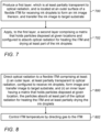
- processor 20 and/or controller 54 when processor 20 and/or controller 54 receive temperature signals 554 and 555 from one or more of temperature sensors 92 (e.g., selected from among temperature sensors 92A-92E), the temperature measured at section 506 is typically higher than the temperature measured at section 502.
- processor 20 and/or controller 54 are configured to determine, based on temperature signals 554 and 555, the highest temperature of blanket 500, using any suitable analysis. For example, processor 20 and/or controller 54 may store a predefined amount (e.g., about 100) of the latest temperature signals 554 and 555. Subsequently, processor 20 and/or controller 54 may select, from among the stored signals, the temperature signals indicative of the top three highest temperatures, and may determine the highest temperature of blanket 500 by calculating a median of the top three highest temperatures.
- processor 20 and/or controller 54 may store a predefined amount (e.g., about 100) of the latest temperature signals 554 and 555. Subsequently, processor 20 and/or controller 54 may select, from among the stored signals, the temperature signals indicative of the top three highest temperatures, and may determine the highest temperature of blanket 500 by calculating a median of the top three highest temperatures.
- processor 20 and/or controller 54 may determine the highest temperature of blanket 500 using any suitable analysis of temperature signals 554 and 555.
- processor 20 and/or controller 54 are configured to control temperature one or more of temperature sensors 92A-92E, to measure the temperature of blanket 500 using any other suitable sampling frequency.
- processor 20 and/or controller 54 are configured to control the intensity of IR radiation emitted from sources 111, and the flow rate of pressurized air 101.
- processor 20 and/or controller 54 are configured to reduce the intensity of beams 99 and/or to increase the flow rate of pressurized air 101.
- processor 20 and/or controller 54 are configured to calculate the temperature along different sections of blanket 500, based on any suitable sampling amount of temperature signals 554 and 555.
- processor 20 and/or controller 54 are configured to hold thresholds indicative of the highest and lowest specified temperatures of the printing process, and to maintain the temperature of blanket 500 by controlling at least some of the dryers described above (e.g., main dryer 64 and bottom dryer 75).
- processor 20 and/or controller 54 are configured to control bottom dryer 75 to increase the intensity of beams 99 and/or to reduce the flow rate of pressurized air 101.
- the blanket is typically cooled by the surrounding environment that have physical contact with the blanket.
- the temperature of the air (or other gas) surrounding the blanket, and the temperature of rollers 78 may be substantially smaller than 100°C (e.g., at any temperature between about 25°C and 100°C).
- processor 20 may receive position signals indicative of the positions of respective markers or other reference points of the blanket, as described in Fig. 1 above. Based on the position signals, processor 20 and/or controller 54 are configured to adjust the intensity of beams 99 and/or the flow rate of pressurized air 101, at one or more of the dryers described above.
- processor 20 may associate first specific markers of blanket 500 with sections 502, and second specific markers of blanket 500 with sections 506.
- processor 20 may control main dryer 64 to increase the intensity of beams 99 directed from given source 111 to blanket 500.
- processor 20 may control main dryer 64 to reduce the intensity of beams 99 emitted from given source 111.
- processor 20 and/or controller 54 are configured to set, e.g., in dryers 62, a constant intensity of beams 99 and a constant flow rate of pressurized air 101.
- processor 20 and/or controller 54 are configured to set, e.g., in dryers 62, a constant intensity of beams 99 and a constant flow rate of pressurized air 101.
- a first set of ink droplets disposed at a given position on the blanket surface will partially dry so that a second set of ink droplets applied to the given position later by other print bars will be mixed with the first set of ink droplets so as to produce a specified mixed color at the given location of the blanket.
- processor 20 and/or controller 54 are configured to control the temperature of pressurized air 101 applied to the blanket (e.g., blanket 44 or blanket 500).
- the specified temperature of pressurized air 101 may be about 30°C.
- Systems 10 and 110 may operate at various countries and seasons having a broad range of environmental temperatures, For example, the environmental temperature may range between about 45°C in the summer at warm countries and about -30°C in the winter at cold countries.
- systems 10 and 110 are configured to filter ink byproducts from the hot air extracted from surface 106 of blanket 44 by AOC 123.
- processor 20 and/or controller 54 are configured to control AIC 122 to mix between the hot filtered air and the air of the environment so as to have air at about 30°C pressurized and applied to blanket 44.
- processor 20 and/or controller 54 are configured to control AIC 122 to mix between the hot air of the environment and air cooled (e.g., using an air conditioning system or any other technique) by a print shop using system 10 or 110 so as to have air at about 30°C, and to pressurize and apply the mixed air to blanket 44.
- air cooled e.g., using an air conditioning system or any other technique
- systems 10 and 110 comprise a current sensor (not shown) coupled to an electrical cable (not shown) supplying electrical current to source 111.
- the current sensor is configured to sense the inductance level on the electrical cable.
- processor 20 and/or controller 54 are configured to receive from the current sensor a signal indicative of the electrical current flowing through the electrical cable and to determine whether or not the respective source 111 is functional.
- Fig. 6 is a diagram that schematically illustrates a sectional view of a process sequence for producing a blanket 600, in accordance with an embodiment of the present invention.
- Blanket 600 may replace, for example, blanket 44 of any of systems 10 and 110 and features thereof shown and described in Figs. 1-5 above.
- the process begins with preparing on a carrier (not shown), an exemplary stack of six layers comprising blanket 600.
- the carrier may be formed of a flexible foil, such as a flexible foil comprising aluminum, nickel, and/or chromium.
- the foil comprises a sheet of aluminized polyethylene terephthalate (PET), also referred to herein as a polyester, e.g., PET coated with fumed aluminum metal.
- PET polyethylene terephthalate
- the carrier may be formed of an antistatic polymeric film, for example, a polyester film.
- the properties of the antistatic film may be obtained using various techniques, such as addition of various additives, e.g., an ammonium salt, to the polymeric composition.
- the carrier has a polished flat surface (not shown) having a roughness (Ra) on an order of 50nm or less, also referred to herein as a carrier contact surface.
- a fluid first curable composition (not shown) is provided and a release layer 602 is formed therefrom on the carrier contact surface.
- release layer 602 comprises an ink reception surface 612 configured to receive the ink image, e.g., from image forming station 60, and to transfer the ink image to a target substrate, such as sheet 50, shown and described in Fig. 1 above.
- layer 602, and particularly surface 612 are configured to have low release force to the ink image, measured by a wetting angle, also referred to herein as a receding contact angle (RCA), between surface 612 and the ink image, as will be described below.
- a wetting angle also referred to herein as a receding contact angle (RCA)
- release layer 602 may comprise a transparent silicon elastomer, such as a vinyl-terminated polydimethylsiloxane (PDMS), or from any other suitable type of a silicone polymer, and may have an exemplary thickness of about 10 ⁇ m - 15 ⁇ m, or any other suitable thickness larger than about 10 ⁇ m.
- PDMS vinyl-terminated polydimethylsiloxane
- the fluid first curable material comprises a vinyl-functional silicone polymer, e.g., a vinyl-silicone polymer comprising at least one lateral vinyl group in addition to the terminal vinyl groups, for example, a vinyl-functional polydimethyl siloxane.
- a vinyl-functional silicone polymer e.g., a vinyl-silicone polymer comprising at least one lateral vinyl group in addition to the terminal vinyl groups, for example, a vinyl-functional polydimethyl siloxane.
- the fluid first curable material may comprise a vinyl-terminated polydimethylsiloxane, a vinyl-functional polydimethylsiloxane comprising at least one lateral vinyl group on the polysiloxane chain in addition to the terminal vinyl groups, a crosslinker, and an addition-cure catalyst, and optionally further comprises a cure retardant.
- release layer 602 may be uniformly applied to the PET-based carrier, leveled to a thickness of 5-200 ⁇ m, and cured for approximately 2-10 minutes at 120-130°C.
- the hydrophobicity of ink transfer surface 612 may have a RCA of about 60°, with a 0.5-5 microliter ( ⁇ l) droplet of distilled water.
- a surface of release layer 602 (that in contact with a surface 614 that will be described below) may have a RCA that is significantly higher, typically around 90°.
- PET carriers used to produce ink-transfer surface 612 may have a typical RCA of 40° or less. All contact angle measurements were carried out using a Contact Angle analyzer "Easy Drop" FM40Mk2 produced by Krüss TM Gmbh, Borsteler Clice 85, 22453 Hamburg, Germany and/or using a Dataphysics OCA15 Pro, produced by Particle and Surface Sciences Pty. Ltd., Gosford, NSW, Australia.
- blanket 600 comprises an IR layer 603 having an exemplary thickness range of about 30 ⁇ m - 150 ⁇ m, and configured to absorb the entire IR radiation of beam 99 or a significant portion thereof.
- IR layer 603 is adapted to absorb, within the top 5 ⁇ thereof, about 50% of the IR radiation of beam 99.
- IR layer 603 is substantially opaque to beam 99.
- IR layer 603 is applied to release layer 602 and has surface 612 interfacing therewith, and a surface 618 interfacing with a compliance layer 604 described in detail below.
- IR layer 603 comprises a matrix made from silicone (e.g., PDMS) and multiple particles 622 disposed at given locations within the bulk of the PDMS matrix of layer 603.
- particles 622 comprise a suitable type of pigment, such as but not limited to off-the-shelf carbon black (CB) particles, each of which having a typical diameter range between about 10 ⁇ m (for IR layer 603 thickness of about 30 ⁇ m) and 30 ⁇ m (for IR layer 603 thickness of about 50 ⁇ m).
- CB off-the-shelf carbon black
- particles 622 are embedded at the bulk of IR layer 603, within a distance 616 of about 10 ⁇ m or 20 ⁇ m from surface 614. Particles 622 are also arranged uniformly along layer 603 at a distance 617 of about 0.1 ⁇ m - 5 ⁇ m from one another. In other embodiments, distances 616 and 617 may be altered between different blankets, for example, at least one particle may be in close proximity or in contact with any of surfaces 614 or 618. Similarly, distance 617 may vary along IR layer 603.
- having particles 622 embedded within the bulk of IR layer 603, rather than at surface 614, may improve the adhesive force between IR layer 603 and release layer 602.
- having particles 622 embedded within the bulk of IR layer 603 may improve the adhesive force between IR layer 603 and compliance layer 604.
- IR layer 603, having the CB particles is coated on the cured release layer and also cured.
- the insertion of the CB particles, or any other suitable type of particles into IR layer 603, may be carried out by mixing the particles in the matrix of the IR layer before applying the layer to the release layer, or by disposing the particles after applying the IR layer to the release layer, or using any other suitable technique.
- PDMS layer is coated on top of the cured IR layer, and fiber glass layer is applied and all structure is cured. Finally, silicone resin is coated on fiber glass fabric and cured.
- the CB particles and the position thereof may affect the drying process of the ink applied to surface 612 of release layer 602, as will be described in detail below.
- blanket 600 comprises compliance layer 604, also referred to herein as a conformal layer, typically made from PDMS and may comprise a black pigment additive.
- Compliance layer 604 is applied to IR layer 603 and may have a typical thickness of about 150 ⁇ m or any other suitable thickness equal to or larger than about 100 ⁇ m.
- compliance layer 604 may have mechanical properties (e.g., greater resistance to tension) that differ, for example, from release layer 602 and IR layer 603. Such desired differences in properties may be obtained, e.g., by utilizing a different composition with respect to release layer 602 and/or IR layer 603, by varying the proportions between the ingredients used to prepare the formulation of release layer 602 and/or IR layer 603, and/or by the addition of further ingredients to such formulation, and/or by the selection of different curing conditions. For example, adding filler particles may increase the mechanical strength of compliance layer 604 relative to release layer 602 and/or IR layer 603.
- mechanical properties e.g., greater resistance to tension
- compliance layer 604 has elastic properties that allows release layer 602 and surface 612 to follow closely the surface contour of a substrate onto which an ink image is impressed (e.g., sheet 50).
- the attachment of compliance layer 602 to the side opposite to ink-transfer surface 612 may involve the application of an adhesive or bonding composition in addition to the material of compliance layer 602.
- blanket 600 comprises reinforcement stacked layers, also referred to herein as a support layer 607 or a skeleton of blanket 600, which is applied to compliance layer 604 and is described in detail below.
- support layer 607 is configured to provide blanket 600 with an improved mechanical resistance to deformation or tearing that may be caused by the torque applied to blanket 600, e.g., by rollers 78 and dancer assembly 74.
- the skeleton of blanket 600 comprises an adhesion layer 606, made from PDMS or any other suitable material, which is formed together with a woven fiberglass layer 608.
- layers 606 and 608 may have typical thickness of about 150 ⁇ m and about 112 ⁇ m, respectively, or any other suitable thickness, such that the thickness of support layer 607 is typically about 200 ⁇ m.
- the skeleton may be produced using any other suitable process, e.g., by disposing layer 606 and subsequently coupling layer 608 thereto and polymerizing, or by using any other process sequence.
- the polymerization process may be based on hydrosilylation reaction catalyzed by platinum catalyzed, commercially known as "addition cure.”
- the skeleton of blanket 600 may comprise any suitable fiber reinforcement, in the form of a web or a fabric, to provide blanket 600 with sufficient structural integrity to withstand stretching when blanket 600 is held in tension, e.g., in system 10.
- the skeleton may be formed by coating the fiber reinforcement with any suitable resin that is subsequently cured and remains flexible after curing.
- support layer 607 may be separately formed, such that fibers embedded and/or impregnated within an independently cured resin.
- support layer 607 may be attached to compliance layer 604 via an adhesive layer, optionally eliminating the need to cure support layer 607 in situ.
- support layer 607, whether formed in situ on compliance layer 604 or separately, may have a thickness of between about 100 ⁇ m and about 500 ⁇ m, part of which is attributed to the thickness of the fibers or the fabric, which thickness generally varies between about 50 ⁇ m and 300 ⁇ m. Note that thickness of support layer 607 is not limited to the above values.
- blanket 600 comprises a high-friction layer 610, also referred to herein as a grip layer, made from a typically transparent PDMS and configured to make physical contact between blanket 600 and the rollers and dancers of system 10 and 110 described, respectively, in Figs. 1 and 2 above.
- layer 610 is made from relatively soft materials, the surface facing the rollers has high friction so that blanket 600 will withstand the torque applied by the rollers and dancers without sliding.
- layer 610 may have a thickness of about 100 ⁇ m, but may alternatively have any other suitable thickness, e.g., between 10 ⁇ m and 1 mm.
- print bars 62 of image forming station 60 apply the ink droplets to surface 106 of blanket 44.
- print bars 62 of image forming station 60 apply the ink droplets to surface 612 of release layer 602.
- the CB content of particles 622 is configured to absorb the IR radiation of beams 99 passing through release layer 602.
- particles 622 are configured to have a temperature larger than the temperature of the silicone matrix of IR layer 603.
- the CB particles absorb the IR radiation and emit heat waves 620 and 621 across IR layer 603.
- heat waves 620 and 621 are increasing the temperature of layers 602 and 604, respectively.
- the silicone matrix of IR layer 603 has low thermal conductivity so that heat waves 620 are progressing within IR layer 603 and are forming a uniform increased temperature across IR layer 603 and release layer 602.
- the CB particles may be embedded in release layer 602.
- release layer 602 (which is transparent to IR radiation) on top of IR layer 603 (which is configured to absorb the IR radiation) is capturing heat waves 620 and 621 within blanket 600 and is, thereby, expediting the drying process of the ink droplets applied to surface 612.
- the heat produced by heat waves 620 may accumulate between and within layers 602 and 603 and the low thermal conductivity of these layers allowing the heat to be distributed uniformly across surface 612 of blanket 600.
- IR layer 603 is applied to release layer 602.
- IR layer 603 comprises the matrix made from silicone (e.g., PDMS).
- the matrix holds multiple particles 622 (e.g., carbon black particles) disposed at given locations within the bulk of the PDMS matrix of layer 603, and configured to absorb optical radiation (in the present example IR radiation of beam 99) for heating release layer 602 and drying at least part of the ink droplets applied to ink reception surface 612.
- Step 702 concludes the method of Fig. 7 , however, additional steps for producing blanket 600 are described in detail in Fig. 6 above.
- Fig. 8 is a flow chart that schematically illustrates a method for drying ink and controlling the temperature of a blanket during a digital printing process, in accordance with an embodiment of the present invention.
- blanket refers to blanket 44 of Figs. 1-4 , to blanket 500 of Fig. 5 , to blanket 600 of Fig. 6 , and to any other sort of suitable ITM.
- Embodiments of the method of Fig. 8 are described using blanket 600, but are applicable for all the types of blankets and ITMs described above, and for other suitable types of ITMs.
- the method begins at an optical radiation direction step 800, with directing IR radiation, such as beam 99, to surface 612 of release layer 602, which is at least partially transparent to the optical radiation, and is configured to: (i) receive the ink droplets, (ii) form the image thereon, and (iii) transfer the image to target substrate, such as sheet 50 or web 51.
- IR radiation of beam 99 is absorbed by particles 622 (e.g., carbon black particles) disposed at given locations within the bulk of the PDMS matrix of layer 603.
- the IR radiation when absorbed by particles 622, heats release layer 602 and at least partially dries the ink droplets of the ink image formed on the surface of the release layer.
- processor 20 controls the temperature control assembly to direct gas (in the present example, pressurized air) at a predefined flow rate for controlling the temperature of the blanket, e.g., to about 70°C or 80°C as described in Figs. 1 and 2 above.
- gas in the present example, pressurized air
- dryer 66 comprises one or more openings to AIC 122, having the air blower and configured to supply pressurized air 101 (or any other type of suitable gas) into dryer 66.
- dryer 66 further comprises one or more openings to AOC 123, having the air extraction apparatus (e.g., a suitable type of vacuum or negative pressure pump) configured to draw pressurized air 101 after cooling the blanket.
- the air extraction apparatus e.g., a suitable type of vacuum or negative pressure pump
- the embodiments described herein mainly address drying of an intermediate transfer member in a digital printing system
- the methods and systems described herein can also be used in other applications, such as in drying liquid from any substrate, or in other applications, such as but not limited to heating or annealing or curing of any substrate.
Landscapes
- Engineering & Computer Science (AREA)
- General Engineering & Computer Science (AREA)
- Health & Medical Sciences (AREA)
- General Health & Medical Sciences (AREA)
- Toxicology (AREA)
- Ink Jet (AREA)
- Supply, Installation And Extraction Of Printed Sheets Or Plates (AREA)
- Drying Of Solid Materials (AREA)
Claims (15)
- System (10), umfassend:ein flexibles Zwischenübertragungselement (ITM), umfassend einen Stapel aus mindestens(i) einer ersten Schicht (602), die an einer äußeren Fläche des ITM angeordnet und so konfiguriert ist, dass sie Tintentröpfchen von einem Tintenzufuhr-Subsystem mit mehreren Druckstäben, die entlang einer Achse angeordnet sind, aufnimmt, um die Tintentröpfchen mit mehreren Farben auf die erste Schicht aufzubringen, um ein Tintenbild auf der ersten Schicht zu erzeugen bzw. das Tintenbild auf ein Zielsubstrat zu übertragen, und(ii) eine zweite Schicht (603), umfassend eine Matrix, die Partikel (622) an jeweiligen gegebenen Stellen hält, wobei die zweite Schicht so konfiguriert ist, dass sie optische Strahlung empfängt, die durch die erste Schicht hindurchtritt, und wobei die Partikel so konfiguriert sind, dass sie das ITM durch Absorption mindestens eines Teils der optischen Strahlung erwärmen;eine Beleuchtungsanordnung (99), die so konfiguriert ist, dass sie die Tintentröpfchen trocknet, indem sie die optische Strahlung so lenkt, dass sie auf mindestens einige der Partikel trifft, wobei die Beleuchtungsanordnung eine Anordnung aus einer Vielzahl von Lichtquellen umfasst, die entlang der Achse angeordnet und mit den mehreren Druckstäben verschachtelt sind; undeine Temperatursteuerbaugruppe (121), die so konfiguriert ist, dass sie eine Temperatur des ITM steuert, indem sie ein Gas zu dem ITM leitet, wobei die Beleuchtungsbaugruppe und die Temperatursteuerbaugruppe in einem Gehäuse zusammengepackt sind, das mindestens einen Hohlraum aufweist, der dem Substrat zugewandt ist, und wobei mindestens ein Paar von Lichtquellen unter den Paaren von Lichtquellen innerhalb des Hohlraums angeordnet ist.
- System nach Anspruch 1, wobei die erste und die zweite Schicht aneinander angrenzen und wobei die Partikel in einem vorgegebenen Abstand voneinander angeordnet sind, um die Außenfläche gleichmäßig zu erwärmen.
- System nach Anspruch 1, wobei die Partikel in einem Großteil der zweiten Schicht in einem vorgegebenen Abstand von der Außenfläche eingebettet sind, um die Außenfläche gleichmäßig zu erwärmen.
- System nach einem der Ansprüche 1-3, und umfassend einen Prozessor, der so konfiguriert ist, dass er ein Temperatursignal empfängt, das eine Temperatur des ITM anzeigt, und auf der Grundlage des Temperatursignals mindestens eines von (i) einer Intensität der optischen Strahlung und (ii) einer Strömungsrate des Gases steuert.
- System nach einem der Ansprüche 1-3, wobei die optische Strahlung Infrarot (IR) Strahlung umfasst und wobei mindestens eines der Partikel Ruß (CB) umfasst.
- System nach Anspruch 5, und umfassend einen Reflektor, der zwischen dem Hohlraum und dem Paar Lichtquellen gekoppelt ist und so konfiguriert ist, dass er einen ersten Teil der von dem Paar Lichtquellen emittierten IR-Strahlung empfängt und einen zweiten Teil der IR-Strahlung, der kleiner als der erste Teil ist, in Richtung des Substrats reflektiert.
- System nach Anspruch 6, wobei mindestens ein Teil eines dritten Teils der IR-Strahlung, die eine Differenz zwischen dem ersten und dem zweiten Teil der IR-Strahlung ist, in dem Reflektor absorbiert wird und eine Wärme erzeugt, und umfassend eine Wärmeübertragungsanordnung (HTA), die um den Reflektor angeordnet ist und so konfiguriert ist, dass sie mindestens einen Teil der in dem Reflektor erzeugten Wärme ableitet.
- System nach Anspruch 7, wobei die HTA eine oder beide Rippen und Spuren umfasst, die so konfiguriert sind, dass sie die in dem Reflektor erzeugte Wärme leiten.
- System nach Anspruch 7, wobei die Temperatursteuerbaugruppe mindestens einen Lufteinlasskanal (AIC), der so konfiguriert ist, dass er das Gas in den Trockner leitet, um das Gas auf eine Fläche des Substrats zu leiten, um das Substrat zu kühlen, und mindestens einen Luftauslasskanal (AOC) umfasst, der so konfiguriert ist, dass er das Gas von der Fläche weg und aus dem Trockner heraus saugt.
- System nach Anspruch 9, wobei das Gas eine druckbeaufschlagte Luft umfasst, wobei die AIC ein Luftgebläse umfasst, das so konfiguriert ist, dass es die druckbeaufschlagte Luft in den Trockner leitet und die druckbeaufschlagte Luft entlang eines ersten Strömungswegs in dem Trockner strömen lässt.
- System nach Anspruch 9,
wobei der AOC eine Luftabsaugvorrichtung umfasst, die so konfiguriert ist, dass sie die druckbeaufschlagte Luft: (i) von dem Substrat in dem Trockner entlang eines zweiten Strömungswegs, der sich vom ersten Strömungsweg unterscheidet, und (ii) aus dem Trockner heraus saugt. - System nach Anspruch 11, wobei die Luftabsaugvorrichtung eine Vakuumpumpe umfasst.
- System nach Anspruch 11, und umfassend eine erste Öffnung zwischen dem Gehäuse und einer ersten Seite der HTA und eine zweite Öffnung an einer zweiten Seite der HTA gegenüber der ersten Seite, wobei der erste Strömungsweg durch die erste Öffnung verläuft und der zweite Strömungsweg durch die zweite Öffnung verläuft.
- System nach Anspruch 11, wobei die Anordnung ein zusätzliches Paar Lichtquellen, einen zusätzlichen Reflektor und eine zusätzliche HTA umfasst, die zwischen (i) der zweiten Öffnung und (ii) einer dritten Öffnung zwischen dem Gehäuse und der zusätzlichen HTA angeordnet sind, wobei der AIC so konfiguriert ist, dass er eine zusätzliche druckbeaufschlagte Luft entlang eines dritten Strömungswegs durch die dritte Öffnung in Richtung des Substrats strömen lässt, um die zusätzliche HTA zu kühlen, und wobei der AOC so konfiguriert ist, dass er die zusätzliche druckbeaufschlagte Luft entlang des zweiten Strömungswegs saugt.
- System nach Anspruch 14, wobei das Paar Lichtquellen und das zusätzliche Paar Lichtquellen entlang der Achse angeordnet sind und in einem gleichem Abstand von dem Substrat angeordnet sind.
Applications Claiming Priority (2)
| Application Number | Priority Date | Filing Date | Title |
|---|---|---|---|
| US201962939726P | 2019-11-25 | 2019-11-25 | |
| PCT/IB2020/060552 WO2021105806A1 (en) | 2019-11-25 | 2020-11-10 | Drying ink in digital printing using infrared radiation absorbed by particles embedded inside itm |
Publications (3)
| Publication Number | Publication Date |
|---|---|
| EP4066064A1 EP4066064A1 (de) | 2022-10-05 |
| EP4066064A4 EP4066064A4 (de) | 2024-01-10 |
| EP4066064B1 true EP4066064B1 (de) | 2025-06-04 |
Family
ID=76129206
Family Applications (1)
| Application Number | Title | Priority Date | Filing Date |
|---|---|---|---|
| EP20894753.1A Active EP4066064B1 (de) | 2019-11-25 | 2020-11-10 | System zum trocknen von tinte im digitaldruck mit infrarotstrahlung, die von in einem itm eingebetteten partikeln absorbiert wird |
Country Status (5)
| Country | Link |
|---|---|
| US (2) | US11833813B2 (de) |
| EP (1) | EP4066064B1 (de) |
| JP (2) | JP7685995B2 (de) |
| CN (1) | CN114746813A (de) |
| WO (1) | WO2021105806A1 (de) |
Families Citing this family (24)
| Publication number | Priority date | Publication date | Assignee | Title |
|---|---|---|---|---|
| US9643403B2 (en) | 2012-03-05 | 2017-05-09 | Landa Corporation Ltd. | Printing system |
| US11809100B2 (en) | 2012-03-05 | 2023-11-07 | Landa Corporation Ltd. | Intermediate transfer members for use with indirect printing systems and protonatable intermediate transfer members for use with indirect printing systems |
| US9498946B2 (en) | 2012-03-05 | 2016-11-22 | Landa Corporation Ltd. | Apparatus and method for control or monitoring of a printing system |
| WO2013136220A1 (en) | 2012-03-15 | 2013-09-19 | Landa Corporation Limited | Endless flexible belt for a printing system |
| US12053978B2 (en) | 2012-03-05 | 2024-08-06 | Landa Corporation Ltd. | Digital printing system |
| GB201401173D0 (en) | 2013-09-11 | 2014-03-12 | Landa Corp Ltd | Ink formulations and film constructions thereof |
| GB2536489B (en) | 2015-03-20 | 2018-08-29 | Landa Corporation Ltd | Indirect printing system |
| CN109689371B (zh) | 2016-05-30 | 2021-12-14 | 兰达公司 | 数字印刷方法 |
| GB201609463D0 (en) | 2016-05-30 | 2016-07-13 | Landa Labs 2012 Ltd | Method of manufacturing a multi-layer article |
| US11298963B2 (en) | 2017-11-29 | 2022-04-12 | Landa Corporation Ltd. | Protection of components of digital printing systems |
| US10994528B1 (en) | 2018-08-02 | 2021-05-04 | Landa Corporation Ltd. | Digital printing system with flexible intermediate transfer member |
| WO2020035766A1 (en) | 2018-08-13 | 2020-02-20 | Landa Corporation Ltd. | Correcting distortions in digital printing by implanting dummy pixels in a digital image |
| JP7246496B2 (ja) | 2018-10-08 | 2023-03-27 | ランダ コーポレイション リミテッド | 印刷システムおよび方法に関する摩擦低減手段 |
| CN113272144B (zh) * | 2018-12-24 | 2023-04-04 | 兰达公司 | 数字印刷系统和方法 |
| JP7654558B2 (ja) | 2019-03-31 | 2025-04-01 | ランダ コーポレイション リミテッド | 印刷プロセスにおける印刷不良を防ぐか、または最小限にするためのシステムおよび方法 |
| US11820130B2 (en) | 2019-04-03 | 2023-11-21 | Landa Corporation Ltd. | Preventing damage to printed substrates conveyed in a printing system |
| EP4066064B1 (de) | 2019-11-25 | 2025-06-04 | Landa Corporation Ltd. | System zum trocknen von tinte im digitaldruck mit infrarotstrahlung, die von in einem itm eingebetteten partikeln absorbiert wird |
| EP4264377A4 (de) | 2021-02-02 | 2024-11-13 | Landa Corporation Ltd. | Abschwächung von verzerrungen in druckbildern |
| WO2023069115A1 (en) | 2021-10-22 | 2023-04-27 | Hewlett-Packard Development Company, L.P. | Image transfer for liquid electro-photographic printing |
| JP2025501188A (ja) | 2022-01-04 | 2025-01-17 | ランダ コーポレイション リミテッド | 中間転写部材 |
| JP2026515089A (ja) * | 2022-10-28 | 2026-05-14 | テトラ ラバル ホールディングス アンド ファイナンス エス エイ | ラミネート包装材料の製造方法および製造装置 |
| US20260208478A1 (en) * | 2023-01-02 | 2026-07-23 | Landa Corporation Ltd. | Intermediate transfer member with paper-based layer |
| US20260217019A1 (en) * | 2023-01-15 | 2026-07-30 | Landa Corporation Ltd. | Controlling a printing process |
| JP2025043039A (ja) * | 2023-09-15 | 2025-03-28 | キヤノン株式会社 | 記録装置 |
Family Cites Families (919)
| Publication number | Priority date | Publication date | Assignee | Title |
|---|---|---|---|---|
| GB748821A (en) | 1950-09-29 | 1956-05-09 | British Broadcasting Corp | Improvements in and relating to television cameras |
| US2839181A (en) | 1954-12-31 | 1958-06-17 | Adamson Stephens Mfg Co | Movable tubular conveyor belt |
| NL235287A (de) | 1958-01-20 | |||
| US3053319A (en) | 1960-12-14 | 1962-09-11 | Beloit Iron Works | Web dewatering apparatus |
| US3235772A (en) | 1961-08-08 | 1966-02-15 | Gurin Emanuel | Anti-static printer's blanket in combination with grounded metal roller |
| JPS4843941B1 (de) | 1968-05-27 | 1973-12-21 | ||
| US3697551A (en) | 1968-12-31 | 1972-10-10 | Hercules Inc | Silane sulfonyl azides |
| BE758713A (fr) | 1969-11-12 | 1971-05-10 | Rhone Poulenc Sa | Iminoxyorganoxysilanes |
| NL175512C (nl) | 1970-04-17 | 1984-11-16 | Jonkers Cornelius Otto | Werkwijze voor het bedrijven van een bandtransporteur voor stortgoed en bandtransporteur, geschikt voor het uitvoeren van deze werkwijze. |
| CA977818A (en) | 1972-06-30 | 1975-11-11 | Carl H. Hertz | Liquid jet recorder with contact image transfer to plural continuous paper webs |
| US3837878A (en) | 1972-12-04 | 1974-09-24 | Gen Electric | Process for treating silica fillers |
| US3902798A (en) | 1974-03-15 | 1975-09-02 | Magicam Inc | Composite photography system |
| JPS50137744A (de) | 1974-04-20 | 1975-11-01 | ||
| US3935055A (en) | 1974-08-30 | 1976-01-27 | Nupla Corporation | Assembly tool for use in attaching fiberglass tool handles |
| US3914540A (en) | 1974-10-03 | 1975-10-21 | Magicam Inc | Optical node correcting circuit |
| US3947113A (en) | 1975-01-20 | 1976-03-30 | Itek Corporation | Electrophotographic toner transfer apparatus |
| DE2632243C3 (de) | 1976-07-17 | 1979-08-30 | Heidelberger Druckmaschinen Ag, 6900 Heidelberg | Auf variable Bogenlängen einstellbare Umführtrommel für Druckmaschinen |
| US4093764A (en) | 1976-10-13 | 1978-06-06 | Dayco Corporation | Compressible printing blanket |
| JPS5578904A (en) | 1978-12-11 | 1980-06-14 | Haruo Yokoyama | Teeth of slide fastner |
| JPS5581163A (en) | 1978-12-13 | 1980-06-18 | Ricoh Co Ltd | Recorder |
| JPS57121446U (de) | 1981-01-24 | 1982-07-28 | ||
| JPS57159865A (en) | 1981-03-27 | 1982-10-02 | Toray Silicone Co Ltd | Primer composition for bonding |
| JPS58174950A (ja) | 1982-04-08 | 1983-10-14 | Manabu Fukuda | 輪転印刷用帯状凸版 |
| US4542059A (en) | 1982-08-23 | 1985-09-17 | Canon Kabushiki Kaisha | Recording medium |
| US4520048A (en) | 1983-01-17 | 1985-05-28 | International Octrooi Maatschappij "Octropa" B.V. | Method and apparatus for coating paper and the like |
| JPS59171975A (ja) | 1983-03-19 | 1984-09-28 | Ricoh Co Ltd | 転写型静電記録方法 |
| US4538156A (en) | 1983-05-23 | 1985-08-27 | At&T Teletype Corporation | Ink jet printer |
| JPS6076343A (ja) | 1983-10-03 | 1985-04-30 | Toray Ind Inc | インクジエツト染色方法 |
| JPS60199692A (ja) | 1984-03-23 | 1985-10-09 | Seiko Epson Corp | 印写装置 |
| EP0183795A1 (de) | 1984-06-18 | 1986-06-11 | The Gillette Company | Pigmentierte wässrige tintenzusammensetzungen und verfahren |
| US4555437A (en) | 1984-07-16 | 1985-11-26 | Xidex Corporation | Transparent ink jet recording medium |
| US4575465A (en) | 1984-12-13 | 1986-03-11 | Polaroid Corporation | Ink jet transparency |
| JPS6223783A (ja) | 1985-07-25 | 1987-01-31 | Canon Inc | 感熱転写記録方法 |
| US4792473A (en) | 1986-10-31 | 1988-12-20 | Endura Tape, Inc. | Self adhesive wallboard tape |
| JPS63274572A (ja) | 1987-05-01 | 1988-11-11 | Canon Inc | 画像形成装置 |
| JP2529651B2 (ja) | 1987-06-22 | 1996-08-28 | 大阪シ−リング印刷株式会社 | 熱転写性インクおよびそれを使用した熱転写用シ−ト |
| US4867830A (en) | 1988-05-26 | 1989-09-19 | Chung Nan Y | Method of tabbing pressure sensitive tape |
| US4853737A (en) | 1988-05-31 | 1989-08-01 | Eastman Kodak Company | Roll useful in electrostatography |
| US4976197A (en) | 1988-07-27 | 1990-12-11 | Ryobi, Ltd. | Reverse side printing device employing sheet feed cylinder in sheet-fed printer |
| US5039339A (en) | 1988-07-28 | 1991-08-13 | Eastman Kodak Company | Ink composition containing a blend of a polyester and an acrylic polymer |
| US5062364A (en) | 1989-03-29 | 1991-11-05 | Presstek, Inc. | Plasma-jet imaging method |
| EP0425439B1 (de) | 1989-10-26 | 1995-08-02 | Ciba-Geigy Ag | Wässerige Drucktinten für den Tintenstrahldruck |
| WO1991007470A1 (fr) | 1989-11-21 | 1991-05-30 | Seiko Epson Corporation | Encre pour impression a jet d'encre |
| US6009284A (en) | 1989-12-13 | 1999-12-28 | The Weinberger Group, L.L.C. | System and method for controlling image processing devices from a remote location |
| JP3181284B2 (ja) | 1990-01-12 | 2001-07-03 | 旭電化工業株式会社 | エネルギー線反応性粘着剤組成物 |
| JPH03248170A (ja) | 1990-02-27 | 1991-11-06 | Fujitsu Ltd | 両面印刷機構 |
| US5075731A (en) | 1990-03-13 | 1991-12-24 | Sharp Kabushiki Kaisha | Transfer roller device |
| JPH0698814B2 (ja) | 1990-03-13 | 1994-12-07 | 富士ゼロックス株式会社 | インク記録媒体の再生方法 |
| US5012072A (en) | 1990-05-14 | 1991-04-30 | Xerox Corporation | Conformable fusing system |
| US5365324A (en) | 1990-10-12 | 1994-11-15 | Canon Kabushiki Kaisha | Multi-image forming apparatus |
| US5099256A (en) | 1990-11-23 | 1992-03-24 | Xerox Corporation | Ink jet printer with intermediate drum |
| CA2059867A1 (en) | 1991-02-13 | 1992-08-14 | Miles Inc. | Binder and vehicle for inks and other color formulations |
| US5128091A (en) | 1991-02-25 | 1992-07-07 | Xerox Corporation | Processes for forming polymeric seamless belts and imaging members |
| US5246100A (en) | 1991-03-13 | 1993-09-21 | Illinois Tool Works, Inc. | Conveyor belt zipper |
| US5352507A (en) | 1991-04-08 | 1994-10-04 | W. R. Grace & Co.-Conn. | Seamless multilayer printing blanket |
| US5777576A (en) | 1991-05-08 | 1998-07-07 | Imagine Ltd. | Apparatus and methods for non impact imaging and digital printing |
| US5575873A (en) | 1991-08-06 | 1996-11-19 | Minnesota Mining And Manufacturing Company | Endless coated abrasive article |
| US5552875A (en) | 1991-08-14 | 1996-09-03 | Indigo N.V. | Method and apparatus for forming duplex images on a substrate |
| JP3223927B2 (ja) | 1991-08-23 | 2001-10-29 | セイコーエプソン株式会社 | 転写式記録装置 |
| WO1993007000A1 (en) | 1991-10-04 | 1993-04-15 | Indigo N.V. | Ink-jet printer |
| JPH05147208A (ja) | 1991-11-30 | 1993-06-15 | Mita Ind Co Ltd | インクジエツトプリンタ |
| JP2778331B2 (ja) | 1992-01-29 | 1998-07-23 | 富士ゼロックス株式会社 | インクジェット記録装置 |
| JPH05249870A (ja) | 1992-03-10 | 1993-09-28 | Matsushita Electric Ind Co Ltd | 感光体ベルト |
| JPH06171076A (ja) | 1992-12-07 | 1994-06-21 | Seiko Epson Corp | 転写型インクジェットプリンタ |
| US5349905A (en) | 1992-03-24 | 1994-09-27 | Xerox Corporation | Method and apparatus for controlling peak power requirements of a printer |
| JP3036226B2 (ja) | 1992-04-20 | 2000-04-24 | 富士ゼロックス株式会社 | 画像形成装置の転写材搬送装置 |
| TW219419B (en) | 1992-05-21 | 1994-01-21 | Ibm | Mobile data terminal with external antenna |
| JPH06954A (ja) | 1992-06-17 | 1994-01-11 | Seiko Epson Corp | インクジェット記録方法 |
| EP0606490B1 (de) | 1992-07-02 | 1998-05-27 | Seiko Epson Corporation | Tintenstrahlaufzeichnungsverfahren durch zwischenübertragung |
| US5264904A (en) | 1992-07-17 | 1993-11-23 | Xerox Corporation | High reliability blade cleaner system |
| EP0583168B1 (de) | 1992-08-12 | 1998-10-28 | Seiko Epson Corporation | Verfahren und Vorrichtung für Tintenstrahlaufzeichnung |
| US5757390A (en) | 1992-08-12 | 1998-05-26 | Hewlett-Packard Company | Ink volume sensing and replenishing system |
| JPH06100807A (ja) | 1992-09-17 | 1994-04-12 | Seiko Instr Inc | 記録用インク |
| US5502476A (en) | 1992-11-25 | 1996-03-26 | Tektronix, Inc. | Method and apparatus for controlling phase-change ink temperature during a transfer printing process |
| US5902841A (en) | 1992-11-25 | 1999-05-11 | Tektronix, Inc. | Use of hydroxy-functional fatty amides in hot melt ink jet inks |
| US5305099A (en) | 1992-12-02 | 1994-04-19 | Joseph A. Morcos | Web alignment monitoring system |
| JP3314971B2 (ja) | 1993-01-28 | 2002-08-19 | 理想科学工業株式会社 | 孔版印刷用エマルジョンインク |
| JP3074105B2 (ja) | 1993-05-13 | 2000-08-07 | 株式会社桜井グラフィックシステムズ | 枚葉印刷機の枚葉紙反転機構 |
| JPH06345284A (ja) | 1993-06-08 | 1994-12-20 | Seiko Epson Corp | ベルト搬送装置及びこれを用いた中間転写型インクジェット記録装置 |
| US5333771A (en) | 1993-07-19 | 1994-08-02 | Advance Systems, Inc. | Web threader having an endless belt formed from a thin metal strip |
| US5677719A (en) | 1993-09-27 | 1997-10-14 | Compaq Computer Corporation | Multiple print head ink jet printer |
| JPH07112841A (ja) | 1993-10-18 | 1995-05-02 | Canon Inc | シート搬送装置及び画像形成装置 |
| JPH07186453A (ja) | 1993-12-27 | 1995-07-25 | Toshiba Corp | カラー画像形成装置 |
| TW339028U (en) | 1994-02-14 | 1998-08-21 | Manfred R Kuehnle | Transport apparatus with electrostatic substrate retention |
| JPH07238243A (ja) | 1994-03-01 | 1995-09-12 | Seiko Instr Inc | 記録用インク |
| US5642141A (en) | 1994-03-08 | 1997-06-24 | Sawgrass Systems, Inc. | Low energy heat activated transfer printing process |
| JPH07278490A (ja) | 1994-04-06 | 1995-10-24 | Dainippon Toryo Co Ltd | 水性被覆組成物 |
| DE59503051D1 (de) | 1994-06-03 | 1998-09-10 | Ferag Ag | Kontrollverfahren zur Anwendung bei der Herstellung von Druckprodukten und Anordnung zur Durchführung des Verfahrens |
| US5614933A (en) | 1994-06-08 | 1997-03-25 | Tektronix, Inc. | Method and apparatus for controlling phase-change ink-jet print quality factors |
| WO1996004339A1 (en) | 1994-08-02 | 1996-02-15 | Lord Corporation | Aqueous silane adhesive compositions |
| NL9401352A (nl) | 1994-08-22 | 1996-04-01 | Oce Nederland Bv | Inrichting voor het overdragen van tonerbeelden. |
| JPH0862999A (ja) | 1994-08-26 | 1996-03-08 | Toray Ind Inc | 中間転写体およびこれを用いた画像形成方法 |
| US5932659A (en) | 1994-09-19 | 1999-08-03 | Sentinel Products Corp. | Polymer blend |
| US5929129A (en) | 1994-09-19 | 1999-07-27 | Sentinel Products Corp. | Crosslinked foamable compositions of silane-grafted, essentially linear polyolefins blended with polypropylene |
| KR960010734A (ko) | 1994-09-19 | 1996-04-20 | 존 디. 밤바라 | 필수 선형 폴리올레핀의 교차- 결합된 발포 구조 및 그 제조방법 |
| US5883144A (en) | 1994-09-19 | 1999-03-16 | Sentinel Products Corp. | Silane-grafted materials for solid and foam applications |
| JP3720396B2 (ja) | 1994-10-17 | 2005-11-24 | 富士写真フイルム株式会社 | 感熱転写記録材料 |
| IL111845A (en) | 1994-12-01 | 2004-06-01 | Hewlett Packard Indigo Bv | Imaging apparatus and method and liquid toner therefor |
| JPH08272224A (ja) | 1995-03-30 | 1996-10-18 | Ricoh Co Ltd | 多色画像形成装置および中間転写体の張力調整方法 |
| US6108513A (en) | 1995-04-03 | 2000-08-22 | Indigo N.V. | Double sided imaging |
| IL113235A (en) | 1995-04-03 | 2006-07-17 | Hewlett Packard Indigo Bv | Double sided imaging |
| US5532314A (en) | 1995-05-03 | 1996-07-02 | Lord Corporation | Aqueous silane-phenolic adhesive compositions, their preparation and use |
| JPH08333531A (ja) | 1995-06-07 | 1996-12-17 | Xerox Corp | 水性インクジェットインク組成物 |
| US5679463A (en) | 1995-07-31 | 1997-10-21 | Eastman Kodak Company | Condensation-cured PDMS filled with zinc oxide and tin oxide mixed fillers for improved fusing member materials |
| US5780412A (en) | 1995-08-09 | 1998-07-14 | The Sherwin-Williams Company | Alkaline-stable hard surface cleaning compounds combined with alkali-metal organosiliconates |
| TW300204B (de) | 1995-08-25 | 1997-03-11 | Avery Dennison Corp | |
| JPH09123432A (ja) | 1995-11-02 | 1997-05-13 | Mita Ind Co Ltd | 転写型インクジェット記録装置 |
| US5683841A (en) | 1995-11-17 | 1997-11-04 | Fuji Photo Film Co., Ltd. | Method for preparation of waterless lithographic printing plate by electrophotographic process |
| JP3301295B2 (ja) | 1995-12-01 | 2002-07-15 | 東洋インキ製造株式会社 | 微細化した顔料の製造方法 |
| US6554189B1 (en) | 1996-10-07 | 2003-04-29 | Metrologic Instruments, Inc. | Automated system and method for identifying and measuring packages transported through a laser scanning tunnel |
| JP3597289B2 (ja) | 1995-12-28 | 2004-12-02 | 花王株式会社 | 伸縮性素材及びその製造方法並びにそれを用いた製品 |
| EP0784244B1 (de) | 1996-01-10 | 2003-03-12 | Canon Kabushiki Kaisha | Zwischenübertragungselement und dieses enthaltendes elektrophotografisches Gerät |
| US6811840B1 (en) | 1996-02-23 | 2004-11-02 | Stahls' Inc. | Decorative transfer process |
| KR20000004983A (ko) | 1996-03-28 | 2000-01-25 | 스프레이그 로버트 월터 | 유기 광 수용체용 퍼플루오로에테르 박리 코팅 |
| JPH09268266A (ja) | 1996-04-01 | 1997-10-14 | Toyo Ink Mfg Co Ltd | インクジェット記録液 |
| JP3758232B2 (ja) | 1996-04-15 | 2006-03-22 | セイコーエプソン株式会社 | 像担持体ベルトの駆動機構 |
| US5660108A (en) | 1996-04-26 | 1997-08-26 | Presstek, Inc. | Modular digital printing press with linking perfecting assembly |
| JPH09300678A (ja) | 1996-05-20 | 1997-11-25 | Mitsubishi Electric Corp | 記録装置 |
| JP3737562B2 (ja) | 1996-05-31 | 2006-01-18 | 富士写真フイルム株式会社 | 画像形成装置 |
| JP3225889B2 (ja) | 1996-06-27 | 2001-11-05 | 富士ゼロックス株式会社 | 静電潜像現像剤用トナー、その製造方法、静電潜像現像剤及び画像形成方法 |
| JP3658765B2 (ja) | 1996-08-01 | 2005-06-08 | セイコーエプソン株式会社 | 二液を用いたインクジェット記録方法 |
| US5736250A (en) | 1996-08-08 | 1998-04-07 | Xerox Corporation | Crosslinked latex polymer surfaces and methods thereof |
| JP3802616B2 (ja) | 1996-08-19 | 2006-07-26 | シャープ株式会社 | インクジェット記録方法 |
| DE69712279D1 (de) | 1996-08-22 | 2002-06-06 | Sony Corp | Drucker und Druckverfahren |
| US5889534A (en) | 1996-09-10 | 1999-03-30 | Colorspan Corporation | Calibration and registration method for manufacturing a drum-based printing system |
| US5733698A (en) | 1996-09-30 | 1998-03-31 | Minnesota Mining And Manufacturing Company | Release layer for photoreceptors |
| JPH10119429A (ja) | 1996-10-11 | 1998-05-12 | Arkwright Inc | インクジェットインク吸収被膜合成物 |
| US5978638A (en) | 1996-10-31 | 1999-11-02 | Canon Kabushiki Kaisha | Intermediate transfer belt and image forming apparatus adopting the belt |
| JPH10130597A (ja) | 1996-11-01 | 1998-05-19 | Sekisui Chem Co Ltd | 硬化型粘接着シート及びその製造方法 |
| US5777650A (en) | 1996-11-06 | 1998-07-07 | Tektronix, Inc. | Pressure roller |
| JP3216799B2 (ja) | 1996-11-13 | 2001-10-09 | 松下電工株式会社 | 加熱定着ロール |
| US6221928B1 (en) | 1996-11-15 | 2001-04-24 | Sentinel Products Corp. | Polymer articles including maleic anhydride |
| JP2938403B2 (ja) | 1996-12-13 | 1999-08-23 | 住友ゴム工業株式会社 | 印刷用ブランケット |
| US6072976A (en) | 1996-12-17 | 2000-06-06 | Bridgestone Corporation | Intermediate transfer member for electrostatic recording |
| US5761595A (en) | 1997-01-21 | 1998-06-02 | Xerox Corporation | Intermediate transfer members |
| US6071368A (en) | 1997-01-24 | 2000-06-06 | Hewlett-Packard Co. | Method and apparatus for applying a stable printed image onto a fabric substrate |
| GB2321616B (en) | 1997-01-29 | 1999-11-17 | Bond A Band Transmissions Ltd | Band joining system |
| US5698018A (en) | 1997-01-29 | 1997-12-16 | Eastman Kodak Company | Heat transferring inkjet ink images |
| US6354700B1 (en) | 1997-02-21 | 2002-03-12 | Ncr Corporation | Two-stage printing process and apparatus for radiant energy cured ink |
| US5891934A (en) | 1997-03-24 | 1999-04-06 | Hewlett-Packard Company | Waterfast macromolecular chromophores using amphiphiles |
| US6720367B2 (en) | 1997-03-25 | 2004-04-13 | Seiko Epson Corporation | Ink composition comprising cationic, water-soluble resin |
| US6024018A (en) | 1997-04-03 | 2000-02-15 | Intex Israel Technologies Corp., Ltd | On press color control system |
| DE69810001T2 (de) | 1997-04-28 | 2003-04-17 | Seiko Epson Corp., Tokio/Tokyo | Tintenzusammensetzung zum Herstellung eines lichtechten Bildes |
| US6551716B1 (en) | 1997-06-03 | 2003-04-22 | Indigo N.V. | Intermediate transfer blanket and method of producing the same |
| WO1999001516A1 (de) | 1997-06-30 | 1999-01-14 | Basf Aktiengesellschaft | Pigmentzubereitungen für das ink-jet-verfahren |
| KR200147792Y1 (ko) | 1997-06-30 | 1999-06-15 | 윤종용 | 습식 전자사진방식 프린터 |
| JPH1184893A (ja) | 1997-07-07 | 1999-03-30 | Fuji Xerox Co Ltd | 中間転写体及び中間転写体を用いた画像形成装置 |
| KR200151066Y1 (ko) | 1997-07-18 | 1999-07-15 | 윤종용 | 칼라 레이저 프린터 |
| JPH1191147A (ja) | 1997-07-22 | 1999-04-06 | Ricoh Co Ltd | 画像形成方法及びその装置 |
| US5865299A (en) | 1997-08-15 | 1999-02-02 | Williams; Keith | Air cushioned belt conveyor |
| US6397034B1 (en) | 1997-08-29 | 2002-05-28 | Xerox Corporation | Fluorinated carbon filled polyimide intermediate transfer components |
| AU3749297A (en) | 1997-09-11 | 1999-03-25 | Scapa Group Plc | Filter belt guide |
| US6053307A (en) | 1997-09-19 | 2000-04-25 | Honda Sangyo Kabushiki Kaisha | Apparatus for changing and guiding running direction of conveyor belt |
| US6045817A (en) | 1997-09-26 | 2000-04-04 | Diversey Lever, Inc. | Ultramild antibacterial cleaning composition for frequent use |
| US6827018B1 (en) | 1997-09-26 | 2004-12-07 | Heidelberger Druckmaschinen Ag | Device and method for driving a printing machine with multiple uncoupled motors |
| JPH11106081A (ja) | 1997-10-01 | 1999-04-20 | Ricoh Co Ltd | 電子写真装置の感光ベルト寄止め機構 |
| US6471803B1 (en) | 1997-10-24 | 2002-10-29 | Ray Pelland | Rotary hot air welder and stitchless seaming |
| US6024786A (en) | 1997-10-30 | 2000-02-15 | Hewlett-Packard Company | Stable compositions of nano-particulate unmodified pigments and insoluble colorants in aqueous microemulsions, and principle of stability and methods of formation thereof |
| JPH11138740A (ja) | 1997-11-05 | 1999-05-25 | Nikka Kk | ドクターブレードの製造方法 |
| JP3634952B2 (ja) | 1997-11-18 | 2005-03-30 | 株式会社金陽社 | 電子機器用転写ベルトの製造方法 |
| JP4033363B2 (ja) | 1997-11-28 | 2008-01-16 | リコープリンティングシステムズ株式会社 | 転写ベルトおよびそれを用いた電子写真装置 |
| KR100252101B1 (ko) | 1997-12-12 | 2000-04-15 | 윤종용 | 습식 현상기의 현상액 공급방법 |
| DE69818411T2 (de) | 1997-12-26 | 2004-06-24 | Ricoh Co., Ltd. | Tintenstrahldrucken unter Verwendung von Viskositätsverbessernde Schicht |
| US6155669A (en) | 1998-01-08 | 2000-12-05 | Xerox Corporation | Pagewidth ink jet printer including a printbar mounted encoding system |
| US6126777A (en) | 1998-02-20 | 2000-10-03 | Lord Corporation | Aqueous silane adhesive compositions |
| US6199971B1 (en) | 1998-02-24 | 2001-03-13 | Arrray Printers Ab | Direct electrostatic printing method and apparatus with increased print speed |
| US6213580B1 (en) | 1998-02-25 | 2001-04-10 | Xerox Corporation | Apparatus and method for automatically aligning print heads |
| US6499822B1 (en) | 1998-04-27 | 2002-12-31 | Canon Kabushiki Kaisha | Method and apparatus for forming an image on a recording medium with contraction and expansion properties |
| TW445214B (en) | 1998-04-30 | 2001-07-11 | Hewlett Packard Co | Inkjet ink level detection |
| JPH11327315A (ja) | 1998-05-12 | 1999-11-26 | Brother Ind Ltd | 転写装置及び画像形成装置 |
| US6912952B1 (en) | 1998-05-24 | 2005-07-05 | Hewlett-Packard Indigo B.V. | Duplex printing system |
| US6608979B1 (en) | 1998-05-24 | 2003-08-19 | Indigo N.V. | Charger for a photoreceptor |
| US6109746A (en) | 1998-05-26 | 2000-08-29 | Eastman Kodak Company | Delivering mixed inks to an intermediate transfer roller |
| US6234625B1 (en) | 1998-06-26 | 2001-05-22 | Eastman Kodak Company | Printing apparatus with receiver treatment |
| US6625331B1 (en) | 1998-07-03 | 2003-09-23 | Minolta Co., Ltd. | Image forming apparatus |
| US6195112B1 (en) | 1998-07-16 | 2001-02-27 | Eastman Kodak Company | Steering apparatus for re-inkable belt |
| EP0985715B1 (de) | 1998-09-01 | 2011-10-12 | Mitsubishi Chemical Corporation | Aufzeichnungsflüssigkeit, Druckprodukt und Tintenstrahlaufzeichnungsverfahren |
| JP2000094660A (ja) | 1998-09-22 | 2000-04-04 | Brother Ind Ltd | 画像形成装置 |
| JP2000103052A (ja) | 1998-09-29 | 2000-04-11 | Brother Ind Ltd | 画像形成装置 |
| JP2000108334A (ja) | 1998-09-30 | 2000-04-18 | Brother Ind Ltd | 画像形成装置 |
| JP2000108320A (ja) | 1998-09-30 | 2000-04-18 | Brother Ind Ltd | 画像形成装置 |
| JP2000108337A (ja) | 1998-09-30 | 2000-04-18 | Brother Ind Ltd | 画像形成装置 |
| US6053438A (en) | 1998-10-13 | 2000-04-25 | Eastman Kodak Company | Process for making an ink jet ink |
| US6166105A (en) | 1998-10-13 | 2000-12-26 | Eastman Kodak Company | Process for making an ink jet ink |
| JP3712547B2 (ja) | 1998-10-30 | 2005-11-02 | 三菱重工業株式会社 | 枚葉印刷機械の給紙制御方法及び不正給紙検知装置 |
| JP2000141710A (ja) | 1998-11-10 | 2000-05-23 | Brother Ind Ltd | 画像形成装置 |
| JP2000141883A (ja) | 1998-11-18 | 2000-05-23 | Ricoh Co Ltd | インクジェット記録方法と被記録材の再生方法および被記録材並びにインク |
| JP2000169772A (ja) | 1998-12-07 | 2000-06-20 | Toyo Ink Mfg Co Ltd | インクジェット用記録液およびそれを用いたインクジェット記録方法 |
| JP2000168062A (ja) | 1998-12-09 | 2000-06-20 | Brother Ind Ltd | インクジェットプリンタ |
| US7239407B1 (en) | 1998-12-16 | 2007-07-03 | Silverbrook Research Pty Ltd | Controller for controlling printing on both surfaces of a sheet of print media |
| US6586100B1 (en) | 1998-12-16 | 2003-07-01 | Nexpress Solutions Llc | Fluorocarbon-silicone interpenetrating network useful as fuser member coating |
| US6262207B1 (en) | 1998-12-18 | 2001-07-17 | 3M Innovative Properties Company | ABN dispersants for hydrophobic particles in water-based systems |
| US5991590A (en) | 1998-12-21 | 1999-11-23 | Xerox Corporation | Transfer/transfuse member release agent |
| EP1013466A3 (de) | 1998-12-22 | 2001-05-02 | E.I. Du Pont De Nemours And Company | Farbstoffempfangsfolie für den Transferdruck |
| JP2000190468A (ja) | 1998-12-25 | 2000-07-11 | Brother Ind Ltd | 画像形成装置 |
| JP3943742B2 (ja) | 1999-01-11 | 2007-07-11 | キヤノン株式会社 | 画像形成装置及び中間転写ベルト |
| US6455132B1 (en) | 1999-02-04 | 2002-09-24 | Kodak Polychrome Graphics Llc | Lithographic printing printable media and process for the production thereof |
| US7304753B1 (en) | 1999-03-11 | 2007-12-04 | Electronics For Imaging, Inc. | Systems for print job monitoring |
| US6678068B1 (en) | 1999-03-11 | 2004-01-13 | Electronics For Imaging, Inc. | Client print server link for output peripheral device |
| JP2000343025A (ja) | 1999-03-31 | 2000-12-12 | Kyocera Corp | 印刷用掻き取りブレード及びその加工方法 |
| DE19916474A1 (de) * | 1999-04-13 | 2000-10-26 | Ist Metz Gmbh | Bestrahlungsgerät |
| US6270074B1 (en) | 1999-04-14 | 2001-08-07 | Hewlett-Packard Company | Print media vacuum holddown |
| AUPP996099A0 (en) | 1999-04-23 | 1999-05-20 | Silverbrook Research Pty Ltd | A method and apparatus(sprint01) |
| DE60017117D1 (de) | 1999-04-23 | 2005-02-03 | Foto Wear Inc | Beschichtetes übertragungsblatt mit wärme- und/oder uv-härtbarem material |
| JP2000337464A (ja) | 1999-05-27 | 2000-12-05 | Fuji Xerox Co Ltd | 無端ベルトおよび画像形成装置 |
| US6917437B1 (en) | 1999-06-29 | 2005-07-12 | Xerox Corporation | Resource management for a printing system via job ticket |
| DE19934282A1 (de) | 1999-07-21 | 2001-01-25 | Degussa | Wäßrige Rußdispersionen |
| US6335046B1 (en) | 1999-07-29 | 2002-01-01 | Sara Lee Bakery Group, Inc. | Method and apparatus for molding dough |
| US6136081A (en) | 1999-08-10 | 2000-10-24 | Eastman Kodak Company | Ink jet printing method |
| JP4118563B2 (ja) | 1999-08-13 | 2008-07-16 | ビーエーエスエフ ソシエタス・ヨーロピア | 着色剤調製物 |
| US6261688B1 (en) | 1999-08-20 | 2001-07-17 | Xerox Corporation | Tertiary amine functionalized fuser fluids |
| JP2001088430A (ja) | 1999-09-22 | 2001-04-03 | Kimoto & Co Ltd | インクジェット記録材料 |
| CN1182442C (zh) | 1999-10-15 | 2004-12-29 | 株式会社理光 | 感光体组件及图像形成装置 |
| JP3631129B2 (ja) | 1999-11-12 | 2005-03-23 | キヤノン株式会社 | インクセット及び被記録媒体への着色部の形成方法 |
| JP2001139865A (ja) | 1999-11-18 | 2001-05-22 | Sharp Corp | 水性インク組成物 |
| FR2801836B1 (fr) | 1999-12-03 | 2002-02-01 | Imaje Sa | Imprimante a fabrication simplifiee et procede de realisation |
| JP4196241B2 (ja) | 1999-12-07 | 2008-12-17 | Dic株式会社 | 水性インク組成物及び水性インク製造方法 |
| JP2001347747A (ja) | 1999-12-24 | 2001-12-18 | Ricoh Co Ltd | 画像粘度設定方法及び装置、粘度画像の転写方法及び装置、該粘度画像の分離方法及び装置及びその粘度画像設定装置、転写装置及び分離装置を用いた画像形成方法及び装置 |
| US6461422B1 (en) | 2000-01-27 | 2002-10-08 | Chartpak, Inc. | Pressure sensitive ink jet media for digital printing |
| JP2001206522A (ja) | 2000-01-28 | 2001-07-31 | Nitto Denko Corp | 蛇行防止ガイド付エンドレスベルト |
| US6741738B2 (en) | 2000-03-13 | 2004-05-25 | Tms, Inc. | Method of optical mark recognition |
| ATE265941T1 (de) | 2000-03-21 | 2004-05-15 | Day Int Inc | Biegsames bildübertragungsgummituch mit undehnbarem träger |
| JP3782920B2 (ja) | 2000-03-28 | 2006-06-07 | セイコーインスツル株式会社 | インク噴射式印刷装置 |
| US6753050B1 (en) | 2000-04-03 | 2004-06-22 | Jody A. Dalvey | Image transfer sheet |
| JP2002020673A (ja) | 2000-04-10 | 2002-01-23 | Seiko Epson Corp | 顔料分散液の製造方法、その方法により得られた顔料分散液、その顔料分散液を用いたインクジェット記録用インク、並びに、そのインクを用いた記録方法および記録物 |
| RU2180675C2 (ru) | 2000-05-11 | 2002-03-20 | ЗАО "Резинотехника" | Адгезивный состав |
| EP1158029A1 (de) | 2000-05-22 | 2001-11-28 | Illinois Tool Works Inc. | Neue Tintenstrahldrucktinten und Druckverfahren |
| JP5121099B2 (ja) | 2000-06-21 | 2013-01-16 | キヤノン株式会社 | インクジェット用インク、及びインクジェット記録方法 |
| JP2002103598A (ja) | 2000-07-26 | 2002-04-09 | Olympus Optical Co Ltd | プリンタ |
| US6648468B2 (en) | 2000-08-03 | 2003-11-18 | Creo Srl | Self-registering fluid droplet transfer methods |
| JP2002049211A (ja) | 2000-08-03 | 2002-02-15 | Pfu Ltd | 液体現像フルカラー電子写真装置 |
| US6755519B2 (en) | 2000-08-30 | 2004-06-29 | Creo Inc. | Method for imaging with UV curable inks |
| US6409331B1 (en) | 2000-08-30 | 2002-06-25 | Creo Srl | Methods for transferring fluid droplet patterns to substrates via transferring surfaces |
| JP4756293B2 (ja) | 2000-08-31 | 2011-08-24 | Dic株式会社 | 高級印刷方法 |
| WO2002020273A1 (en) | 2000-09-04 | 2002-03-14 | Matsushita Electric Industrial Co., Ltd. | Image forming device and recording intermediate belt mounting jig |
| DE60128306T2 (de) | 2000-09-14 | 2008-01-10 | Dai Nippon Printing Co., Ltd. | Zwischentransferaufzeichnungsmedium und Verfahren zur Bildabbildung |
| US6377772B1 (en) | 2000-10-04 | 2002-04-23 | Nexpress Solutions Llc | Double-sleeved electrostatographic roller and method of using |
| US6357870B1 (en) | 2000-10-10 | 2002-03-19 | Lexmark International, Inc. | Intermediate transfer medium coating solution and method of ink jet printing using coating solution |
| DE60134105D1 (de) | 2000-10-13 | 2008-07-03 | Dainippon Screen Mfg | Druckpresse ausgerüstet mit Messapparat zur Messung der Farbfelder |
| JP4246367B2 (ja) | 2000-10-16 | 2009-04-02 | 株式会社リコー | 印刷装置 |
| DE10056703C2 (de) | 2000-11-15 | 2002-11-21 | Technoplot Cad Vertriebs Gmbh | Tintenstrahldrucker mit einem Piezo-Druckkopf zum Ausstoßen von Lactat-Tinte auf ein unbeschichtetes Druckmedium |
| US6363234B2 (en) | 2000-11-21 | 2002-03-26 | Indigo N.V. | Printing system |
| US6633735B2 (en) | 2000-11-29 | 2003-10-14 | Samsung Electronics Co., Ltd. | Reduction of seam mark from an endless seamed organophotoreceptor belt |
| JP2002229276A (ja) | 2000-11-30 | 2002-08-14 | Ricoh Co Ltd | 画像形成装置および方法ならびに画像形成システム |
| US6841206B2 (en) | 2000-11-30 | 2005-01-11 | Agfa-Gevaert | Ink jet recording element |
| US7265819B2 (en) | 2000-11-30 | 2007-09-04 | Hewlett-Packard Development Company, L.P. | System and method for print system monitoring |
| JP2002169383A (ja) | 2000-12-05 | 2002-06-14 | Ricoh Co Ltd | 画像形成装置及び画像形成装置の中間転写体停止位置制御方法 |
| US6400913B1 (en) | 2000-12-14 | 2002-06-04 | Xerox Corporation | Control registration and motion quality of a tandem xerographic machine using transfuse |
| US6475271B2 (en) | 2000-12-28 | 2002-11-05 | Xerox Corporation | Ink jet ink compositions and printing processes |
| US6595615B2 (en) | 2001-01-02 | 2003-07-22 | 3M Innovative Properties Company | Method and apparatus for selection of inkjet printing parameters |
| US6680095B2 (en) | 2001-01-30 | 2004-01-20 | Xerox Corporation | Crosslinking of fluoropolymers with polyfunctional siloxanes for release enhancement |
| JP2002234243A (ja) | 2001-02-09 | 2002-08-20 | Hitachi Koki Co Ltd | インクジェット記録方法 |
| US6623817B1 (en) | 2001-02-22 | 2003-09-23 | Ghartpak, Inc. | Inkjet printable waterslide transferable media |
| US6843976B2 (en) | 2001-02-27 | 2005-01-18 | Noranda Inc. | Reduction of zinc oxide from complex sulfide concentrates using chloride processing |
| DE10113558B4 (de) | 2001-03-20 | 2005-09-22 | Avery Dennison Corp., Pasadena | Kombi-Drucker |
| JP4545336B2 (ja) | 2001-03-21 | 2010-09-15 | 株式会社リコー | ベルト駆動装置及びこれを備えた画像形成装置 |
| US20030018119A1 (en) | 2001-03-28 | 2003-01-23 | Moshe Frenkel | Method and compositions for preventing the agglomeration of aqueous pigment dispersions |
| JP3802362B2 (ja) | 2001-04-03 | 2006-07-26 | 株式会社Pfu | カラー電子写真装置の中間転写体 |
| EP1247821A3 (de) | 2001-04-05 | 2003-10-15 | Kansai Paint Co., Ltd. | Pigment dispergierendes Harz |
| DE10117504A1 (de) | 2001-04-07 | 2002-10-17 | Degussa | Injekt-Tinte |
| US7244485B2 (en) | 2001-04-11 | 2007-07-17 | Xerox Corporation | Imageable seamed belts having polyamide adhesive between interlocking seaming members |
| JP2002307815A (ja) | 2001-04-13 | 2002-10-23 | Konica Corp | インクジェット記録用中間転写媒体、及びインクジェット記録方法 |
| JP3676693B2 (ja) | 2001-04-27 | 2005-07-27 | 京セラミタ株式会社 | ベルト搬送装置及び画像形成装置 |
| JP3994375B2 (ja) | 2001-05-11 | 2007-10-17 | ニッタ株式会社 | ビード付きコンベアベルト |
| US6630047B2 (en) | 2001-05-21 | 2003-10-07 | 3M Innovative Properties Company | Fluoropolymer bonding composition and method |
| US6753087B2 (en) | 2001-05-21 | 2004-06-22 | 3M Innovative Properties Company | Fluoropolymer bonding |
| US6551757B1 (en) | 2001-05-24 | 2003-04-22 | Eastman Kodak Company | Negative-working thermal imaging member and methods of imaging and printing |
| JP2002371208A (ja) | 2001-06-14 | 2002-12-26 | Canon Inc | 中間転写型記録用インクジェットインクおよびインクジェット記録方法 |
| US6558767B2 (en) | 2001-06-20 | 2003-05-06 | Xerox Corporation | Imageable seamed belts having polyvinylbutyral and isocyanate outer layer |
| JP3558056B2 (ja) | 2001-06-27 | 2004-08-25 | セイコーエプソン株式会社 | 画像形成装置 |
| JP3496830B2 (ja) | 2001-06-28 | 2004-02-16 | バンドー化学株式会社 | 高負荷伝動用vベルト |
| US6896944B2 (en) | 2001-06-29 | 2005-05-24 | 3M Innovative Properties Company | Imaged articles comprising a substrate having a primed surface |
| US6806013B2 (en) | 2001-08-10 | 2004-10-19 | Samsung Electronics Co. Ltd. | Liquid inks comprising stabilizing plastisols |
| US6945631B2 (en) | 2001-08-17 | 2005-09-20 | Fuji Photo Film Co., Ltd. | Image forming method and apparatus |
| JP4045759B2 (ja) | 2001-08-20 | 2008-02-13 | 富士ゼロックス株式会社 | 画像形成方法 |
| US6714232B2 (en) | 2001-08-30 | 2004-03-30 | Eastman Kodak Company | Image producing process and apparatus with magnetic load roller |
| US20040105971A1 (en) | 2001-09-05 | 2004-06-03 | Parrinello Luciano M. | Polymer processing of a substantially water-resistant microporous substrate |
| JP2003076159A (ja) | 2001-09-07 | 2003-03-14 | Ricoh Co Ltd | 画像形成装置 |
| US20030055129A1 (en) | 2001-09-17 | 2003-03-20 | Westvaco Corporation | In Jet Inks |
| JP2003094795A (ja) | 2001-09-20 | 2003-04-03 | Ricoh Co Ltd | 画像記録用被記録材及びその記録方法 |
| JP2003107819A (ja) | 2001-09-27 | 2003-04-09 | Kanegafuchi Chem Ind Co Ltd | 樹脂管状成形体およびその製造方法 |
| JP2003114558A (ja) | 2001-10-03 | 2003-04-18 | Yuka Denshi Co Ltd | エンドレスベルト及び画像形成装置 |
| US6719423B2 (en) | 2001-10-09 | 2004-04-13 | Nexpress Solutions Llc | Ink jet process including removal of excess liquid from an intermediate member |
| US6682189B2 (en) | 2001-10-09 | 2004-01-27 | Nexpress Solutions Llc | Ink jet imaging via coagulation on an intermediate member |
| US6557992B1 (en) | 2001-10-26 | 2003-05-06 | Hewlett-Packard Development Company, L.P. | Method and apparatus for decorating an imaging device |
| JP2003202761A (ja) | 2001-11-01 | 2003-07-18 | Canon Inc | 画像形成装置及びそれに着脱可能な中間転写ユニット |
| JP2003145914A (ja) | 2001-11-07 | 2003-05-21 | Konica Corp | インクジェット記録方法およびインクジェット記録装置 |
| US6550905B1 (en) * | 2001-11-19 | 2003-04-22 | Dotrix N.V. | Radiation curable inkjet ink relatively free of photoinitiator and method and apparatus of curing the ink |
| US6639527B2 (en) | 2001-11-19 | 2003-10-28 | Hewlett-Packard Development Company, L.P. | Inkjet printing system with an intermediate transfer member between the print engine and print medium |
| US6779885B2 (en) | 2001-12-04 | 2004-08-24 | Eastman Kodak Company | Ink jet printing method |
| JP2003170645A (ja) | 2001-12-06 | 2003-06-17 | Olympus Optical Co Ltd | 記録用紙及び画像記録装置 |
| US20030113501A1 (en) | 2001-12-14 | 2003-06-19 | Xerox Corporation | Imageable seamed belts having improved adhesive with plasticizer between interlocking seaming members |
| US6606476B2 (en) | 2001-12-19 | 2003-08-12 | Xerox Corporation | Transfix component having haloelastomer and silicone hybrid material |
| AU2002317533A1 (en) | 2002-01-07 | 2003-07-24 | Rohm And Haas Company | Process for preparing emulsion polymers and polymers formed therefrom |
| JP2003211770A (ja) | 2002-01-18 | 2003-07-29 | Hitachi Printing Solutions Ltd | カラー画像記録装置 |
| JP2003219271A (ja) | 2002-01-24 | 2003-07-31 | Nippon Hoso Kyokai <Nhk> | 多地点仮想スタジオ合成システム |
| US6789887B2 (en) | 2002-02-20 | 2004-09-14 | Eastman Kodak Company | Inkjet printing method |
| JP2003246135A (ja) | 2002-02-26 | 2003-09-02 | Ricoh Co Ltd | 画像形成用処理液及び該処理液を用いる画像形成方法 |
| JP2003246484A (ja) | 2002-02-27 | 2003-09-02 | Kyocera Corp | ベルト搬送装置 |
| JP3997990B2 (ja) | 2002-03-08 | 2007-10-24 | ブラザー工業株式会社 | 画像形成装置及びそれに用いられる外側ベルト |
| JP2003267580A (ja) | 2002-03-15 | 2003-09-25 | Fuji Xerox Co Ltd | ベルト搬送装置及びこれを用いた画像形成装置 |
| US6743560B2 (en) | 2002-03-28 | 2004-06-01 | Heidelberger Druckmaschinen Ag | Treating composition and process for toner fusing in electrostatographic reproduction |
| JP2003292855A (ja) | 2002-04-08 | 2003-10-15 | Konica Corp | インクジェット記録用インクおよび画像形成方法 |
| JP4393748B2 (ja) | 2002-04-19 | 2010-01-06 | 株式会社リコー | インクジェット用インク |
| US6911993B2 (en) | 2002-05-15 | 2005-06-28 | Konica Corporation | Color image forming apparatus using registration marks |
| US6881458B2 (en) | 2002-06-03 | 2005-04-19 | 3M Innovative Properties Company | Ink jet receptive coating |
| US7084202B2 (en) | 2002-06-05 | 2006-08-01 | Eastman Kodak Company | Molecular complexes and release agents |
| JP2004011263A (ja) | 2002-06-06 | 2004-01-15 | Sumitomo Denko Steel Wire Kk | Pc鋼材の定着金具 |
| JP2004009632A (ja) | 2002-06-10 | 2004-01-15 | Konica Minolta Holdings Inc | インクジェット記録方法 |
| JP4250748B2 (ja) | 2002-06-14 | 2009-04-08 | フジコピアン株式会社 | 転写シート及び画像転写方法 |
| US6843559B2 (en) | 2002-06-20 | 2005-01-18 | Xerox Corporation | Phase change ink imaging component with MICA-type silicate layer |
| JP2004025708A (ja) | 2002-06-27 | 2004-01-29 | Konica Minolta Holdings Inc | インクジェット記録方法 |
| JP2004034441A (ja) | 2002-07-02 | 2004-02-05 | Konica Minolta Holdings Inc | 画像形成方法 |
| AT411605B (de) | 2002-07-05 | 2004-03-25 | Huyck Austria | Gewebeband-einrichtung |
| EP2226663A1 (de) | 2002-07-15 | 2010-09-08 | Tomoegawa Paper Co. Ltd. | Herstellungsmethode für ein optisches Faserbändchen |
| DE10235872A1 (de) | 2002-07-30 | 2004-02-19 | Ebe Hesterman | Satellitendruckmaschine zum Bedrucken von bogenförmigen Substraten |
| DE10235027A1 (de) | 2002-07-31 | 2004-02-12 | Degussa Ag | Wäßrige, kolloidale, gefrier- und lagerstabile Gasrußsuspension |
| US7066088B2 (en) | 2002-07-31 | 2006-06-27 | Day International, Inc. | Variable cut-off offset press system and method of operation |
| ITBO20020531A1 (it) | 2002-08-08 | 2004-02-09 | Gd Spa | Dispositivo e metodo di giunzione di nastri. |
| JP2004077669A (ja) | 2002-08-13 | 2004-03-11 | Fuji Xerox Co Ltd | 画像形成装置 |
| CA2497536C (en) | 2002-09-03 | 2011-05-10 | Bloomberg Lp | Bezel-less electronic display |
| JP4006374B2 (ja) | 2002-09-04 | 2007-11-14 | キヤノン株式会社 | 画像形成方法、画像形成装置および記録物の製造方法 |
| WO2004022353A1 (en) | 2002-09-04 | 2004-03-18 | Canon Kabushiki Kaisha | Image forming process and image forming apparatus |
| US6816693B2 (en) | 2002-09-13 | 2004-11-09 | Samsung Electronics Co. Ltd. | Apparatus and method for removing carrier liquid from a photoreceptor surface or from a toned image on a photoreceptor |
| JP2004114377A (ja) | 2002-09-24 | 2004-04-15 | Konica Minolta Holdings Inc | インクジェット記録装置及びこの装置に用いるインク |
| JP2004117118A (ja) | 2002-09-25 | 2004-04-15 | Nidec Copal Corp | 液面レベル検出装置 |
| JP2004126380A (ja) | 2002-10-04 | 2004-04-22 | Sumitomo Rubber Ind Ltd | 印刷用転写体 |
| CN100537216C (zh) | 2002-10-07 | 2009-09-09 | 日本写真印刷株式会社 | 转印材料 |
| JP2004148687A (ja) | 2002-10-30 | 2004-05-27 | Mitsubishi Heavy Ind Ltd | バリアブルカットオフ印刷機 |
| US6709096B1 (en) | 2002-11-15 | 2004-03-23 | Lexmark International, Inc. | Method of printing and layered intermediate used in inkjet printing |
| DE10253447A1 (de) | 2002-11-16 | 2004-06-03 | Degussa Ag | Wäßrige, kolloidale Gasrußsuspension |
| JP4375652B2 (ja) | 2002-11-21 | 2009-12-02 | 日本ニュークローム株式会社 | ドクターブレード |
| US6783228B2 (en) | 2002-12-31 | 2004-08-31 | Eastman Kodak Company | Digital offset lithographic printing |
| US6758140B1 (en) | 2002-12-31 | 2004-07-06 | Eastman Kodak Company | Inkjet lithographic printing plates |
| US7407899B2 (en) | 2003-01-10 | 2008-08-05 | Milliken & Company | Textile substrates having layered finish structure for improving liquid repellency and stain release |
| JP2004223956A (ja) | 2003-01-24 | 2004-08-12 | Fuji Photo Film Co Ltd | インクジェット記録用転写媒体及び画像形成方法 |
| JP4264969B2 (ja) | 2003-01-29 | 2009-05-20 | セイコーエプソン株式会社 | 水性顔料インク組成物、並びにこれを用いた記録方法、記録システム及び記録物 |
| ES2450043T3 (es) | 2003-02-14 | 2014-03-21 | Japan As Represented By President Of National Center Of Neurology And Psychiatry Ministry Of Healt | Derivados del glicolípido, proceso para su producción, intermedios para la síntesis del mismo, y proceso para la producción de los intermedios |
| DE10306104B4 (de) | 2003-02-14 | 2005-03-24 | Heidelberger Druckmaschinen Ag | Vorrichtung und Verfahren zur Erkennung der Kante eines Aufzeichnungsmaterials |
| JP4239152B2 (ja) | 2003-02-17 | 2009-03-18 | セイコーエプソン株式会社 | 液体組成物 |
| EP1454968B1 (de) | 2003-03-04 | 2010-04-28 | Seiko Epson Corporation | Dispergierte Pigmente enthaltende wässrige Aufzeichnungsflüssigkeit und bedrucktes Material |
| DE10311219A1 (de) | 2003-03-14 | 2004-09-30 | Werner Kammann Maschinenfabrik Gmbh | Verfahren und Vorrichtung zum Bedrucken einer Bahn |
| JP4275455B2 (ja) | 2003-03-20 | 2009-06-10 | 株式会社リコー | 中間転写体、画像形成装置、画像形成方法、及び画像形成用乾式トナー |
| US7162167B2 (en) | 2003-03-28 | 2007-01-09 | Canon Kabushiki Kaisha | Image forming apparatus, method of adjusting developing unit of the apparatus, developing unit, and storage medium |
| US20040200369A1 (en) | 2003-04-11 | 2004-10-14 | Brady Thomas P. | Method and system for printing press image distortion compensation |
| JP4266693B2 (ja) | 2003-04-24 | 2009-05-20 | キヤノン株式会社 | 画像形成装置 |
| US20040221943A1 (en) | 2003-05-09 | 2004-11-11 | Xerox Corporation | Process for interlocking seam belt fabrication using adhesive tape with release substrate |
| US6984216B2 (en) | 2003-05-09 | 2006-01-10 | Troy Polymers, Inc. | Orthopedic casting articles |
| US7055946B2 (en) | 2003-06-12 | 2006-06-06 | Lexmark International, Inc. | Apparatus and method for printing with an inkjet drum |
| CN100404625C (zh) | 2003-06-20 | 2008-07-23 | 株式会社钟化 | 固化性组合物 |
| JP4054722B2 (ja) | 2003-06-23 | 2008-03-05 | キヤノン株式会社 | 画像形成方法、画像形成装置および記録物の製造方法 |
| JP4054721B2 (ja) | 2003-06-23 | 2008-03-05 | キヤノン株式会社 | 画像形成方法および画像形成装置 |
| EP1638775B1 (de) | 2003-06-23 | 2010-07-28 | Canon Kabushiki Kaisha | Verfahren zur bilderzeugung, bilderzeugungsgerät, zwischenelement, und verfahren zur modifizierung der oberfläche des zwischenelementes |
| JP4674786B2 (ja) | 2003-06-24 | 2011-04-20 | コニカミノルタビジネステクノロジーズ株式会社 | 画像形成装置及び画像形成方法 |
| EP1503326A1 (de) | 2003-07-28 | 2005-02-02 | Hewlett-Packard Development Company, L.P. | Mehrfarbdrucker und Bilddruckverfahren |
| JP4216153B2 (ja) | 2003-09-17 | 2009-01-28 | 株式会社リコー | ベルト搬送装置及びこれを用いた画像形成装置 |
| JP3970826B2 (ja) | 2003-10-02 | 2007-09-05 | 株式会社リコー | 画像形成装置 |
| US7128412B2 (en) | 2003-10-03 | 2006-10-31 | Xerox Corporation | Printing processes employing intermediate transfer with molten intermediate transfer materials |
| DE10347034B4 (de) | 2003-10-09 | 2006-11-09 | J. S. Staedtler Gmbh & Co. Kg | Verwendung einer Tinte |
| US7129858B2 (en) | 2003-10-10 | 2006-10-31 | Hewlett-Packard Development Company, L.P. | Encoding system |
| DE10349049B3 (de) | 2003-10-17 | 2005-06-09 | Interroll Schweiz Ag | Gurtbandförderer mit separaten Führungsschuhen |
| EP1676175B1 (de) | 2003-10-23 | 2009-03-25 | Hewlett-Packard Development Company, L.P. | Gleichzeitige verwendung eines kontaktheizgerätes zum aufheizen eines tonerbildes auf einem zwischenträger und eines internen heizgerätes in diesem zwischenträger |
| US6983692B2 (en) | 2003-10-31 | 2006-01-10 | Hewlett-Packard Development Company, L.P. | Printing apparatus with a drum and screen |
| US20050103437A1 (en) | 2003-11-19 | 2005-05-19 | Carroll James M. | Seaming iron with automatic traction |
| JP4006386B2 (ja) | 2003-11-20 | 2007-11-14 | キヤノン株式会社 | 画像形成方法および画像形成装置 |
| US7065308B2 (en) | 2003-11-24 | 2006-06-20 | Xerox Corporation | Transfer roll engagement method for minimizing media induced motion quality disturbances |
| US7257358B2 (en) | 2003-12-19 | 2007-08-14 | Lexmark International, Inc. | Method and apparatus for detecting registration errors in an image forming device |
| JP4562388B2 (ja) | 2003-12-26 | 2010-10-13 | エスケー化研株式会社 | 水性塗料組成物 |
| JP4091005B2 (ja) | 2004-01-29 | 2008-05-28 | 株式会社東芝 | 電子写真装置 |
| JP2005215645A (ja) | 2004-02-02 | 2005-08-11 | Fuji Xerox Co Ltd | 定着用部材、定着装置、画像定着方法、及び画像形成装置 |
| JP2005224737A (ja) | 2004-02-16 | 2005-08-25 | Mitsubishi Paper Mills Ltd | 塗布液除去方法 |
| JP2005234366A (ja) | 2004-02-20 | 2005-09-02 | Ricoh Co Ltd | 位置ずれ量検出方法及び画像形成装置 |
| US6966712B2 (en) | 2004-02-20 | 2005-11-22 | International Business Machines Corporation | Method and system for minimizing the appearance of image distortion in a high speed inkjet paper printing system |
| US7442244B2 (en) | 2004-03-22 | 2008-10-28 | Seiko Epson Corporation | Water-base ink composition |
| JP4010009B2 (ja) | 2004-03-25 | 2007-11-21 | 富士フイルム株式会社 | 画像記録装置及びメンテナンス方法 |
| JP2005297234A (ja) | 2004-04-07 | 2005-10-27 | Shin Etsu Chem Co Ltd | 熱圧着用シリコーンゴムシート及びその製造方法 |
| DE102004021600A1 (de) | 2004-05-03 | 2005-12-08 | Gretag-Macbeth Ag | Vorrichtung zur Inline-Überwachung der Druckqualität bei Bogenoffsetdruckmaschinen |
| JP2005319593A (ja) | 2004-05-06 | 2005-11-17 | Nippon Paper Industries Co Ltd | インクジェット記録用媒体 |
| US20050266332A1 (en) | 2004-05-28 | 2005-12-01 | Pavlisko Joseph A | Oil-free process for full color digital printing |
| JP4006416B2 (ja) | 2004-06-03 | 2007-11-14 | キヤノン株式会社 | インクジェット記録方法およびインクジェット記録装置 |
| JP2006001688A (ja) | 2004-06-16 | 2006-01-05 | Ricoh Co Ltd | 駆動制御装置と制御方法及び画像形成装置 |
| TWI347344B (en) | 2004-06-29 | 2011-08-21 | Dainippon Ink & Chemicals | Aqueous cationic polyurethane resin dispersion, ink-jet receiving agent comprising the dispersion, and ink-jet recording medium using the same |
| CN100540584C (zh) | 2004-06-29 | 2009-09-16 | 大日本油墨化学工业株式会社 | 阳离子性聚氨酯树脂水分散体、含有其的喷墨接受剂以及使用其制成的喷墨记录介质 |
| US6989052B1 (en) | 2004-06-30 | 2006-01-24 | Xerox Corporation | Phase change ink printing process |
| JP4391898B2 (ja) | 2004-07-06 | 2009-12-24 | 株式会社リコー | ベルト駆動制御装置、ベルト装置及び画像形成装置 |
| BRPI0514355B1 (pt) | 2004-08-20 | 2020-09-08 | Hunter Douglas Inc. | Processo para fabricar uma cobertura para uma abertura arquitetônica |
| MX2007002722A (es) | 2004-09-09 | 2007-05-16 | Wella Ag | Composicion acondiciondora para el cuidado del cabello. |
| US20060066704A1 (en) | 2004-09-28 | 2006-03-30 | Fuji Photo Film Co., Ltd. | Image forming apparatus |
| JP2006095870A (ja) | 2004-09-29 | 2006-04-13 | Fuji Photo Film Co Ltd | インクジェットプリンタ及びその記録方法並びにこのプリンタで用いるインクと記録媒体 |
| US7264328B2 (en) | 2004-09-30 | 2007-09-04 | Xerox Corporation | Systems and methods for print head defect detection and print head maintenance |
| EP1800887B1 (de) | 2004-09-30 | 2009-04-15 | Dai Nippon Printing Co., Ltd. | Wärmeübertragungsschutzsschichtfilm |
| JP2006102975A (ja) | 2004-09-30 | 2006-04-20 | Fuji Photo Film Co Ltd | 吐出装置及び画像記録装置 |
| US7204584B2 (en) | 2004-10-01 | 2007-04-17 | Xerox Corporation | Conductive bi-layer intermediate transfer belt for zero image blooming in field assisted ink jet printing |
| US7459491B2 (en) | 2004-10-19 | 2008-12-02 | Hewlett-Packard Development Company, L.P. | Pigment dispersions that exhibit variable particle size or variable vicosity |
| EP2123722A1 (de) | 2004-10-22 | 2009-11-25 | Seiko Epson Corporation | Tintenstrahlaufzeichnungstinte |
| JP2006139029A (ja) | 2004-11-11 | 2006-06-01 | Ricoh Co Ltd | 移動体へのマーク形成方法およびマーク付き移動体 |
| JP2006137127A (ja) | 2004-11-15 | 2006-06-01 | Konica Minolta Medical & Graphic Inc | インクジェットプリンタ |
| JP4553690B2 (ja) | 2004-11-16 | 2010-09-29 | サン美術印刷株式会社 | 情報担持シート及びそのための印刷インキ |
| JP2006152133A (ja) | 2004-11-30 | 2006-06-15 | Seiko Epson Corp | インクジェットインクおよびインクジェット記録装置 |
| US7575314B2 (en) | 2004-12-16 | 2009-08-18 | Agfa Graphics, N.V. | Dotsize control fluid for radiation curable ink-jet printing process |
| AU2005319179B2 (en) | 2004-12-21 | 2011-10-13 | Dow Global Technologies Llc | Polypropylene-based adhesive compositions |
| US7134953B2 (en) | 2004-12-27 | 2006-11-14 | 3M Innovative Properties Company | Endless abrasive belt and method of making the same |
| RU2282643C1 (ru) | 2004-12-30 | 2006-08-27 | Открытое акционерное общество "Балаковорезинотехника" | Способ крепления резин на основе акрилатных каучуков к металлическим поверхностям |
| JP5090182B2 (ja) | 2005-01-04 | 2012-12-05 | ダウ・コーニング・コーポレイション | オルガノボランアミン錯体によって硬化されたシロキサンおよびシラン |
| WO2006076888A2 (de) | 2005-01-18 | 2006-07-27 | Forbo Siegling Gmbh | Mehrschichtiges band |
| CN103965689B (zh) | 2005-01-18 | 2017-04-12 | 佳能株式会社 | 墨、成套墨、喷墨记录方法、墨盒和喷墨记录设备 |
| US7677716B2 (en) | 2005-01-26 | 2010-03-16 | Hewlett-Packard Development Company, L.P. | Latent inkjet printing, to avoid drying and liquid-loading problems, and provide sharper imaging |
| EP1863886B8 (de) | 2005-02-04 | 2013-12-18 | Ricoh Company, Ltd. | Aufzeichnungstinte, tintensatz, tintenpatrone, tintenaufzeichnung, tintenstrahlaufzeichnungsvorrichtung und tintenstrahlaufzeichnungsverfahren |
| ATE433381T1 (de) | 2005-02-18 | 2009-06-15 | Taiyo Yuden Kk | Optisches informationsaufzeichnungsmaterial und verfahren zu dessen herstellung |
| JP2006224583A (ja) | 2005-02-21 | 2006-08-31 | Konica Minolta Holdings Inc | 搬送部材の粘着力回復方法、搬送装置及び画像記録装置 |
| JP2006234212A (ja) | 2005-02-23 | 2006-09-07 | Matsushita Electric Ind Co Ltd | 冷蔵庫 |
| JP2006231666A (ja) | 2005-02-24 | 2006-09-07 | Seiko Epson Corp | インクジェット記録装置 |
| WO2006091957A2 (en) | 2005-02-24 | 2006-08-31 | E.I. Dupont De Nemours And Company | Selected textile medium for transfer printing |
| JP2006243212A (ja) | 2005-03-02 | 2006-09-14 | Fuji Xerox Co Ltd | 画像形成装置 |
| JP2006256087A (ja) | 2005-03-17 | 2006-09-28 | Ricoh Printing Systems Ltd | インクジェット記録装置 |
| JP2006263984A (ja) | 2005-03-22 | 2006-10-05 | Fuji Photo Film Co Ltd | インクジェット記録方法及び装置 |
| US7322689B2 (en) | 2005-04-25 | 2008-01-29 | Xerox Corporation | Phase change ink transfix pressure component with dual-layer configuration |
| US7296882B2 (en) | 2005-06-09 | 2007-11-20 | Xerox Corporation | Ink jet printer performance adjustment |
| US7592117B2 (en) | 2005-06-16 | 2009-09-22 | Hewlett-Packard Development Company, L.P. | System and method for transferring features to a substrate |
| JP2006347081A (ja) | 2005-06-17 | 2006-12-28 | Fuji Xerox Co Ltd | パターン形成方法およびパターン形成装置 |
| JP4449831B2 (ja) | 2005-06-17 | 2010-04-14 | 富士ゼロックス株式会社 | インク受容性粒子、マーキング材料、インク受容方法、記録方法、及び記録装置 |
| JP2007041530A (ja) | 2005-06-27 | 2007-02-15 | Fuji Xerox Co Ltd | エンドレスベルトおよびそれを用いた画像形成装置 |
| US7506975B2 (en) | 2005-06-28 | 2009-03-24 | Xerox Corporation | Sticky baffle |
| US7233761B2 (en) | 2005-07-13 | 2007-06-19 | Ricoh Company, Ltd. | Method and apparatus for transferring multiple toner images and image forming apparatus |
| JP2007025246A (ja) | 2005-07-15 | 2007-02-01 | Seiko Epson Corp | 画像形成装置 |
| GB0515052D0 (en) | 2005-07-22 | 2005-08-31 | Dow Corning | Organosiloxane compositions |
| JP2007058154A (ja) | 2005-07-26 | 2007-03-08 | Fuji Xerox Co Ltd | 中間転写ベルト、その製造方法、及び画像形成装置 |
| US7907872B2 (en) | 2005-07-29 | 2011-03-15 | Ricoh Company, Ltd. | Imprinting apparatus and an image formation apparatus |
| US7673741B2 (en) | 2005-08-08 | 2010-03-09 | Inter-Source Recovery Systems | Apparatus and method for conveying materials |
| JP4645553B2 (ja) | 2005-08-08 | 2011-03-09 | 富士ゼロックス株式会社 | 電子写真用画像転写シート、及びこれを用いた画像記録体の作製方法、並びに画像記録体 |
| JP4803356B2 (ja) | 2005-08-15 | 2011-10-26 | セイコーエプソン株式会社 | インクセット及びこれを用いた記録方法、記録物 |
| US7655708B2 (en) | 2005-08-18 | 2010-02-02 | Eastman Kodak Company | Polymeric black pigment dispersions and ink jet ink compositions |
| US8044114B2 (en) | 2005-08-23 | 2011-10-25 | Ricoh Company, Ltd. | Ink for recording, and ink cartridge, ink recorded matter, inkjet recording apparatus and inkjet recording method using the same |
| JP4509891B2 (ja) | 2005-08-24 | 2010-07-21 | 株式会社東芝 | ベルト駆動装置 |
| US20070054981A1 (en) | 2005-09-07 | 2007-03-08 | Fuji Photo Film Co., Ltd | Ink set and method and apparatus for recording image |
| JP2007069584A (ja) | 2005-09-09 | 2007-03-22 | Fujifilm Corp | 中間転写回転ドラム及びその製造方法 |
| US7891799B2 (en) | 2005-09-12 | 2011-02-22 | Electronics For Imaging, Inc. | Metallic ink jet printing system for graphics applications |
| JP4783102B2 (ja) | 2005-09-14 | 2011-09-28 | 株式会社リコー | 画像形成装置、および画像形成制御プログラム |
| JP4725262B2 (ja) | 2005-09-14 | 2011-07-13 | 富士フイルム株式会社 | 画像形成装置 |
| US7845786B2 (en) | 2005-09-16 | 2010-12-07 | Fujifilm Corporation | Image forming apparatus and ejection state determination method |
| JP4743502B2 (ja) | 2005-09-20 | 2011-08-10 | 富士フイルム株式会社 | 画像形成装置 |
| ATE486719T1 (de) | 2005-09-30 | 2010-11-15 | Fujifilm Corp | Aufzeichnungsmaterial, flachdruckplatte die dieses aufzeichnungsmaterial verwendet sowie herstellungsverfahren der flachdruckplatte |
| US8122846B2 (en) | 2005-10-26 | 2012-02-28 | Micronic Mydata AB | Platforms, apparatuses, systems and methods for processing and analyzing substrates |
| US8779027B2 (en) | 2005-10-31 | 2014-07-15 | Dic Corporation | Aqueous pigment dispersion liquid and ink-jet recording ink |
| ES2487498T3 (es) | 2005-11-25 | 2014-08-21 | Kba-Notasys Sa | Método para detectar la aparición de errores de impresión en sustratos impresos durante el procesamiento de los mismos en una prensa de imprenta |
| JP4413854B2 (ja) | 2005-11-29 | 2010-02-10 | 株式会社東芝 | 画像形成装置 |
| US7541406B2 (en) | 2005-11-30 | 2009-06-02 | Xerox Corporation | Phase change inks containing curable isocyanate-derived compounds |
| US7658486B2 (en) | 2005-11-30 | 2010-02-09 | Xerox Corporation | Phase change inks |
| US7655707B2 (en) | 2005-12-02 | 2010-02-02 | Hewlett-Packard Development Company, L.P. | Pigmented ink-jet inks with improved image quality on glossy media |
| KR100980746B1 (ko) | 2005-12-22 | 2010-09-07 | 가부시키가이샤 리코 | 안료 분산체, 기록용 잉크, 잉크 카트리지, 잉크젯 기록방법 및 잉크젯 기록 장치 |
| US7926933B2 (en) | 2005-12-27 | 2011-04-19 | Canon Kabushiki Kaisha | Ink jet printing method and ink jet printing apparatus |
| US7543815B2 (en) | 2005-12-28 | 2009-06-09 | Hewlett-Packard Development Company, L.P. | Grippers malfunction monitoring |
| US7527359B2 (en) | 2005-12-29 | 2009-05-05 | Xerox Corporation | Circuitry for printer |
| JP2007190745A (ja) | 2006-01-18 | 2007-08-02 | Fuji Xerox Co Ltd | パターン形成方法およびパターン形成装置 |
| JP2007193005A (ja) | 2006-01-18 | 2007-08-02 | Toshiba Corp | 画像形成装置およびベルト駆動機構ならびにベルト体駆動方法 |
| JP2007216673A (ja) | 2006-01-19 | 2007-08-30 | Brother Ind Ltd | プリント装置及び転写体 |
| US8025388B2 (en) | 2006-02-01 | 2011-09-27 | Fujifilm Corporation | Image forming apparatus and image forming method with decreased image transfer disturbance |
| JP4951990B2 (ja) | 2006-02-13 | 2012-06-13 | 富士ゼロックス株式会社 | 弾性体ロール及び定着装置 |
| CA2643244C (en) | 2006-02-21 | 2015-11-24 | Moore Wallace North America, Inc. | Systems and methods for high speed variable printing |
| JP2007253347A (ja) | 2006-03-20 | 2007-10-04 | Ricoh Co Ltd | 接合部材製造方法、無端状接合ベルト、定着ユニット、中間転写ユニット、画像形成装置、及び、シート接合装置 |
| JP2007268802A (ja) | 2006-03-30 | 2007-10-18 | Fujifilm Corp | 画像形成装置及び画像形成方法 |
| ATE496759T1 (de) | 2006-04-06 | 2011-02-15 | Aisapack Holding Sa | Schlauchförmiger verpackungskörper aus thermoplastmaterial mit eingebettetem streifen |
| JP4387374B2 (ja) | 2006-04-28 | 2009-12-16 | シャープ株式会社 | 画像形成装置、画像形成装置の制御方法、プログラムおよびその記録媒体 |
| US8199359B2 (en) | 2006-04-28 | 2012-06-12 | Kyocera Mita Corporation | System and method for reducing visibility of registration errors in an image to be printed using a digital color printer by convolution with a laplacian kernel |
| JP4752600B2 (ja) | 2006-05-08 | 2011-08-17 | 富士ゼロックス株式会社 | 液滴吐出装置 |
| JP4752599B2 (ja) | 2006-05-08 | 2011-08-17 | 富士ゼロックス株式会社 | 液滴吐出装置 |
| DE102006023111A1 (de) | 2006-05-16 | 2007-11-22 | Werner Kammann Maschinenfabrik Gmbh & Co. Kg | Vorrichtung zum Beschichten von Objekten |
| US7712890B2 (en) | 2006-06-02 | 2010-05-11 | Fujifilm Corporation | Image forming apparatus and image forming method |
| JP2008006816A (ja) | 2006-06-02 | 2008-01-17 | Fujifilm Corp | 画像形成装置および画像形成方法 |
| US20070285486A1 (en) | 2006-06-08 | 2007-12-13 | Xerox Corporation | Low viscosity intermediate transfer coating |
| US7699922B2 (en) | 2006-06-13 | 2010-04-20 | Xerox Corporation | Organic phase change carriers containing nanoparticles, phase change inks including same and methods for making same |
| US8011781B2 (en) | 2006-06-15 | 2011-09-06 | Canon Kabushiki Kaisha | Method of producing recorded product (printed product) and image forming apparatus |
| JP4829843B2 (ja) | 2006-06-15 | 2011-12-07 | キヤノン株式会社 | 記録物(印刷物)の製造方法および画像形成装置 |
| JP4668853B2 (ja) | 2006-06-16 | 2011-04-13 | 株式会社リコー | 電子写真感光体、並びにこれを用いた画像形成装置及びプロセスカートリッジ |
| CN101421110B (zh) | 2006-06-16 | 2011-07-27 | 佳能株式会社 | 记录产品的制造方法及用于该制造方法的中间转印体和图像记录设备 |
| JP2008007652A (ja) | 2006-06-29 | 2008-01-17 | Fujifilm Corp | アゾ色素、感熱転写記録用インクシート、感熱転写記録方法、カラートナー、インクジェット用インクおよびカラーフィルタ |
| JP5085893B2 (ja) | 2006-07-10 | 2012-11-28 | 富士フイルム株式会社 | 画像形成装置及びインクセット |
| JP2008036968A (ja) | 2006-08-07 | 2008-02-21 | Fujifilm Corp | 画像記録装置及び画像記録方法 |
| JP2008044235A (ja) | 2006-08-16 | 2008-02-28 | Fujifilm Corp | インクジェット記録方法及び装置 |
| JP2008049671A (ja) | 2006-08-28 | 2008-03-06 | Fujifilm Corp | 画像形成装置および画像形成方法 |
| US8273273B2 (en) | 2006-08-31 | 2012-09-25 | Konica Minolta Opto, Inc. | Manufacturing method for optical film |
| US7887177B2 (en) | 2006-09-01 | 2011-02-15 | Fuji Xerox Co., Ltd. | Ink-recipient particle, material for recording, recording apparatus and storage member for ink-recipient particle |
| JP4895729B2 (ja) | 2006-09-01 | 2012-03-14 | 富士フイルム株式会社 | インクジェット記録装置 |
| JP4908117B2 (ja) | 2006-09-04 | 2012-04-04 | 富士フイルム株式会社 | インクセット及び画像形成装置並びにその方法 |
| JP2008074018A (ja) | 2006-09-22 | 2008-04-03 | Fujifilm Corp | 画像形成装置 |
| JP4884151B2 (ja) | 2006-09-27 | 2012-02-29 | 株式会社リコー | 位置検知装置、速度検出装置、移動制御装置、ベルト搬送装置、回転体駆動装置、および画像形成装置 |
| JP4907414B2 (ja) * | 2006-09-29 | 2012-03-28 | 富士フイルム株式会社 | インクジェット記録方法及びインクジェット記録装置 |
| US8104810B2 (en) | 2006-11-01 | 2012-01-31 | Norgren Automotive Solutions, Inc. | Gripper having sensor for detecting displacement |
| US8460450B2 (en) | 2006-11-20 | 2013-06-11 | Hewlett-Packard Development Company, L.P. | Rapid drying, water-based ink-jet ink |
| US7665817B2 (en) | 2006-11-29 | 2010-02-23 | Xerox Corporation | Double reflex printing |
| JP2008137239A (ja) | 2006-11-30 | 2008-06-19 | Kyocera Mita Corp | インクジェット記録方法およびインクジェット記録装置 |
| EP1930160B1 (de) | 2006-12-04 | 2008-07-30 | C.B.G. Acciai S.r.l. | Vorgehonte Rakel mit bogenförmigem Lamellenprofil und Herstellungsverfahren für die Rakel |
| JP2008142962A (ja) | 2006-12-07 | 2008-06-26 | Fuji Xerox Co Ltd | インク受容性粒子、記録用の材料、記録装置、及びインク受容性粒子収納カートリッジ |
| US7754298B2 (en) | 2006-12-11 | 2010-07-13 | Hewlett-Packard Development Company, L.P. | Intermediate transfer member and method for making same |
| GB0625530D0 (en) | 2006-12-21 | 2007-01-31 | Eastman Kodak Co | Aqueous inkjet fluid |
| WO2008078841A1 (en) | 2006-12-27 | 2008-07-03 | Ricoh Company, Ltd. | Ink-media set, ink composition, ink cartridge, inkjet recording method, inkjet recording apparatus, and ink recorded matter |
| JP5144243B2 (ja) | 2006-12-28 | 2013-02-13 | 富士フイルム株式会社 | 画像形成方法及び画像形成装置 |
| US20080175612A1 (en) | 2007-01-18 | 2008-07-24 | Ricoh Company, Ltd. | Motor control device and image forming apparatus |
| JP5135809B2 (ja) | 2007-01-26 | 2013-02-06 | 富士ゼロックス株式会社 | ポリイミド膜及びポリイミド無端ベルトの製造装置並びにポリイミド膜及びポリイミド無端ベルトの製造方法 |
| JP4367490B2 (ja) | 2007-01-26 | 2009-11-18 | セイコーエプソン株式会社 | インクジェット記録用インク組成物、記録方法、および記録物 |
| EP2642343B1 (de) | 2007-02-02 | 2015-10-07 | Canon Kabushiki Kaisha | Magenta Toner und Vielfarben-Bilderzeugungsverfahren |
| JP2008194997A (ja) | 2007-02-15 | 2008-08-28 | Fuji Xerox Co Ltd | ベルト回転装置及び画像形成装置 |
| JP2008200899A (ja) | 2007-02-16 | 2008-09-04 | Fuji Xerox Co Ltd | インク受容性粒子、記録用の材料、記録装置、及びインク受容性粒子収納カートリッジ |
| US8733249B2 (en) | 2007-02-20 | 2014-05-27 | Goss International Americas, Inc. | Real-time print product status |
| JP2008201564A (ja) | 2007-02-22 | 2008-09-04 | Fuji Xerox Co Ltd | ベルト回転装置及び画像形成装置 |
| JP5170508B2 (ja) | 2007-03-16 | 2013-03-27 | 株式会社リコー | インクメディアセット、及びインクジェット記録方法、記録物、記録装置 |
| JP2008233357A (ja) | 2007-03-19 | 2008-10-02 | Ricoh Co Ltd | 転写ニップローラ、転写装置及び画像形成装置 |
| JP4442627B2 (ja) | 2007-03-28 | 2010-03-31 | ブラザー工業株式会社 | 画像記録装置 |
| US7997716B2 (en) * | 2007-03-28 | 2011-08-16 | Fujifilm Corporation | UV curable ink-jet recording apparatus |
| JP2008246793A (ja) * | 2007-03-29 | 2008-10-16 | Fujifilm Corp | 活性エネルギー線硬化型インクジェット記録装置 |
| JP2008246787A (ja) | 2007-03-29 | 2008-10-16 | Fujifilm Corp | 溶媒吸収装置及び画像形成装置 |
| JP2008255135A (ja) | 2007-03-30 | 2008-10-23 | Fujifilm Corp | インク及び画像形成方法並びにその装置 |
| JP2008254203A (ja) | 2007-03-30 | 2008-10-23 | Fujifilm Corp | インクジェット記録装置、インクジェット記録方法 |
| JP2008246990A (ja) | 2007-03-30 | 2008-10-16 | Nippon Paper Industries Co Ltd | インクジェット記録媒体 |
| JP2008257118A (ja) | 2007-04-09 | 2008-10-23 | Fuji Xerox Co Ltd | 画像形成装置用の無端状ベルト、画像形成装置用のベルト張架装置および画像形成装置 |
| US7706733B2 (en) | 2007-04-10 | 2010-04-27 | Xerox Corporation | Mechanism for transfix member with idle movement |
| JP5386796B2 (ja) | 2007-05-24 | 2014-01-15 | セイコーエプソン株式会社 | インクジェット記録用インクセットおよびインクジェット記録方法 |
| JP5017684B2 (ja) | 2007-07-13 | 2012-09-05 | 株式会社リコー | ベルト装置および画像形成装置 |
| JP2009025570A (ja) | 2007-07-19 | 2009-02-05 | Ricoh Co Ltd | 画像形成装置、像担持体およびプロセスカートリッジ |
| JP2009037311A (ja) | 2007-07-31 | 2009-02-19 | Dainippon Printing Co Ltd | 偏光板用表面フィルム及びこれを用いた偏光板 |
| JP2009036914A (ja) | 2007-07-31 | 2009-02-19 | Canon Inc | 画像形成装置及び画像形成方法 |
| KR101154896B1 (ko) | 2007-08-06 | 2012-06-18 | 삼성전자주식회사 | 정착유닛 및 이를 포함하는 화상형성장치 |
| JP5213382B2 (ja) | 2007-08-09 | 2013-06-19 | 富士フイルム株式会社 | 水性インク組成物、インクセット、及び画像記録方法 |
| JP2009045794A (ja) | 2007-08-17 | 2009-03-05 | Fujifilm Corp | 画像形成方法及び画像形成装置 |
| WO2009025821A1 (en) | 2007-08-20 | 2009-02-26 | Rr Donnelley | Apparatus and methods for controlling application of a substance to a substrate |
| JP2009045851A (ja) | 2007-08-21 | 2009-03-05 | Fujifilm Corp | 画像形成方法及び装置 |
| JP2009045885A (ja) | 2007-08-22 | 2009-03-05 | Fuji Xerox Co Ltd | 冷却装置、画像形成装置、及び定着装置 |
| JP5051887B2 (ja) | 2007-09-05 | 2012-10-17 | 富士フイルム株式会社 | 液体塗布装置及び方法並びに画像形成装置 |
| EP2037329B1 (de) | 2007-09-13 | 2014-07-02 | Ricoh Company, Ltd. | Bilderzeugungsvorrichtung, Bandeinheit und Bandantriebssteuerverfahren |
| JP4960814B2 (ja) | 2007-09-18 | 2012-06-27 | 富士フイルム株式会社 | 画像形成装置および画像形成装置の制御方法 |
| JP2009069753A (ja) | 2007-09-18 | 2009-04-02 | Oki Data Corp | ベルト回転装置及び画像形成装置 |
| JP4931751B2 (ja) | 2007-09-25 | 2012-05-16 | 富士フイルム株式会社 | 画像形成装置及び画像形成方法 |
| JP5330763B2 (ja) | 2007-09-25 | 2013-10-30 | 富士フイルム株式会社 | 画像形成方法及び画像形成装置 |
| US8042906B2 (en) | 2007-09-25 | 2011-10-25 | Fujifilm Corporation | Image forming method and apparatus |
| JP5247102B2 (ja) | 2007-09-26 | 2013-07-24 | 富士フイルム株式会社 | インクジェット用インク及びその製造方法、並びにインクセット |
| JP2009083324A (ja) | 2007-09-28 | 2009-04-23 | Fujifilm Corp | インクジェット記録方法 |
| JP2009083314A (ja) | 2007-09-28 | 2009-04-23 | Fujifilm Corp | 画像形成方法及びインクジェット記録装置 |
| JP2009083317A (ja) | 2007-09-28 | 2009-04-23 | Fujifilm Corp | 画像形成方法及び画像形成装置 |
| JP2009083325A (ja) | 2007-09-28 | 2009-04-23 | Fujifilm Corp | 画像形成方法及びインクジェット記録装置 |
| JP2009083208A (ja) * | 2007-09-28 | 2009-04-23 | Fujifilm Corp | インクジェット記録装置 |
| US7703601B2 (en) | 2007-10-31 | 2010-04-27 | Habasit Ag | Hybrid mesh belt |
| JP2009116128A (ja) | 2007-11-07 | 2009-05-28 | Fuji Xerox Co Ltd | 定着装置及び画像形成装置 |
| ITMO20070354A1 (it) | 2007-11-23 | 2009-05-24 | Tecno Europa Srl | Apparato e metodo per decorare oggetti |
| CN101177057A (zh) | 2007-11-26 | 2008-05-14 | 杭州远洋实业有限公司 | 一种气垫印刷橡皮布生产工艺 |
| US7873311B2 (en) | 2007-12-05 | 2011-01-18 | Kabushiki Kaisha Toshiba | Belt transfer device for image forming apparatus |
| JP2009148908A (ja) | 2007-12-18 | 2009-07-09 | Fuji Xerox Co Ltd | インクジェット記録用中間転写無端ベルト及び記録装置 |
| JP2009154330A (ja) | 2007-12-25 | 2009-07-16 | Seiko Epson Corp | インクジェット記録方法及びインクジェット記録装置 |
| JP4971126B2 (ja) | 2007-12-26 | 2012-07-11 | 富士フイルム株式会社 | 液体塗布装置 |
| US7526229B1 (en) | 2007-12-27 | 2009-04-28 | Aetas Technology Incorporated | Belt tension mechanism of an image forming device |
| WO2009087789A1 (ja) | 2008-01-04 | 2009-07-16 | Sakura Color Products Corporation | 水変色性布帛シート |
| US7965414B2 (en) | 2008-01-23 | 2011-06-21 | Xerox Corporation | Systems and methods for detecting image quality defects |
| JP5235432B2 (ja) | 2008-01-30 | 2013-07-10 | キヤノン株式会社 | 画像形成装置 |
| JP4513868B2 (ja) | 2008-02-12 | 2010-07-28 | 富士ゼロックス株式会社 | ベルト回転装置及び記録装置 |
| US8287116B2 (en) * | 2008-02-14 | 2012-10-16 | Hewlett-Packard Development Company, L.P. | Printing apparatus and method |
| JP2009190375A (ja) | 2008-02-18 | 2009-08-27 | Fuji Xerox Co Ltd | インク受容性粒子、及び記録装置 |
| US8029123B2 (en) | 2008-02-25 | 2011-10-04 | Fuji Xerox Co., Ltd. | Material set for recording and recording apparatus |
| JP5018547B2 (ja) | 2008-02-26 | 2012-09-05 | 富士ゼロックス株式会社 | 記録装置 |
| JP2009203035A (ja) | 2008-02-28 | 2009-09-10 | Seiko Epson Corp | ベルト斜行補正制御方法、ベルト搬送装置、記録装置 |
| JP2009208349A (ja) | 2008-03-04 | 2009-09-17 | Fujifilm Corp | ノズルプレートの凸部製造方法、ノズルプレート、インクジェットヘッド及び画像形成装置 |
| JP4525778B2 (ja) | 2008-03-07 | 2010-08-18 | 富士ゼロックス株式会社 | 記録用の材料 |
| JP2009214318A (ja) | 2008-03-07 | 2009-09-24 | Fuji Xerox Co Ltd | 記録装置、及び記録用の材料 |
| JP2009214439A (ja) | 2008-03-11 | 2009-09-24 | Fujifilm Corp | インクジェット記録装置及び画像形成方法 |
| CN101249768B (zh) | 2008-03-17 | 2011-02-16 | 汕头市新协特种纸科技有限公司 | 一种可喷墨打印的热转印纸及其制备方法 |
| JP4513912B2 (ja) | 2008-03-21 | 2010-07-28 | 富士ゼロックス株式会社 | 画像形成装置用ベルト、ベルト張架装置及び画像形成装置 |
| KR100963222B1 (ko) * | 2008-03-24 | 2010-06-10 | 주식회사 나래나노텍 | 롤을 이용한 잉크젯 프린팅 장치, 시스템 및 방법 |
| JP5040766B2 (ja) | 2008-03-25 | 2012-10-03 | 富士ゼロックス株式会社 | 記録装置 |
| JP5018585B2 (ja) | 2008-03-24 | 2012-09-05 | 富士ゼロックス株式会社 | 記録装置 |
| US8342672B2 (en) | 2008-03-24 | 2013-01-01 | Fuji Xerox Co., Ltd. | Recording apparatus |
| JP5106199B2 (ja) | 2008-03-25 | 2012-12-26 | 富士フイルム株式会社 | 画像形成方法および画像形成装置 |
| JP2009227909A (ja) | 2008-03-25 | 2009-10-08 | Fujifilm Corp | インクジェット用インクセット、画像記録方法、及び画像記録装置 |
| JP2009226852A (ja) | 2008-03-25 | 2009-10-08 | Fujifilm Corp | インクジェット記録装置および記録方法 |
| JP2009233977A (ja) | 2008-03-26 | 2009-10-15 | Fuji Xerox Co Ltd | 記録用の材料、および記録装置 |
| JP2009234219A (ja) | 2008-03-28 | 2009-10-15 | Fujifilm Corp | 画像形成方法、画像形成装置 |
| JP2009240925A (ja) | 2008-03-31 | 2009-10-22 | Fujifilm Corp | 液体塗布装置、液体塗布方法、インクジェット記録装置、及びインクジェット記録方法 |
| US8038280B2 (en) | 2008-04-09 | 2011-10-18 | Xerox Corporation | Ink-jet printer and method for decurling cut sheet media prior to ink-jet printing |
| EP2270070B1 (de) | 2008-04-22 | 2014-07-30 | Toagosei Co., Ltd | Härtbare zusammensetzung und verfahren zur herstellung einer siliciumorganischen verbindung |
| EP2313279B1 (de) | 2008-05-02 | 2019-03-13 | Hewlett-Packard Development Company, L.P. | Tintenstrahlbildgebungsverfahren, bildgebungsverfahren und hartbildgebungsvorrichtungen |
| JP2009271422A (ja) | 2008-05-09 | 2009-11-19 | Ricoh Co Ltd | 無端ベルト、ベルト装置、中間転写ユニット、及び、画像形成装置 |
| JP4591544B2 (ja) | 2008-05-21 | 2010-12-01 | 富士ゼロックス株式会社 | 補正情報作成装置、画像形成装置及びプログラム |
| JP5353059B2 (ja) | 2008-05-26 | 2013-11-27 | 株式会社リコー | 画像形成方法 |
| JP5137894B2 (ja) | 2008-05-27 | 2013-02-06 | キヤノン株式会社 | カラー画像形成装置 |
| WO2009148102A1 (ja) | 2008-06-03 | 2009-12-10 | キヤノン株式会社 | 画像形成方法および画像形成装置 |
| JP2010000712A (ja) | 2008-06-20 | 2010-01-07 | Fuji Xerox Co Ltd | 画像記録用組成物、画像記録用インクセット、および記録装置 |
| JP5253013B2 (ja) | 2008-06-24 | 2013-07-31 | 富士フイルム株式会社 | 画像形成方法及び装置 |
| JP5203065B2 (ja) | 2008-06-24 | 2013-06-05 | 富士フイルム株式会社 | 液体塗布方法及び画像形成装置 |
| US8136476B2 (en) | 2008-07-18 | 2012-03-20 | Xerox Corporation | Liquid layer applicator assembly |
| US7810922B2 (en) | 2008-07-23 | 2010-10-12 | Xerox Corporation | Phase change ink imaging component having conductive coating |
| US8096650B2 (en) | 2008-07-28 | 2012-01-17 | Xerox Corporation | Duplex printing with integrated image marking engines |
| CN104861890A (zh) | 2008-08-08 | 2015-08-26 | 美国圣戈班性能塑料公司 | 热喷涂遮蔽胶带 |
| JP2010054855A (ja) | 2008-08-28 | 2010-03-11 | Fuji Xerox Co Ltd | 画像形成装置 |
| US8087771B2 (en) | 2008-08-29 | 2012-01-03 | Xerox Corporation | Dual blade release agent application apparatus |
| US7938528B2 (en) | 2008-08-29 | 2011-05-10 | Xerox Corporation | System and method of adjusting blade loads for blades engaging image forming machine moving surfaces |
| JP5317598B2 (ja) | 2008-09-12 | 2013-10-16 | キヤノン株式会社 | プリンタ |
| JP5453750B2 (ja) | 2008-09-17 | 2014-03-26 | 株式会社リコー | インクジェット記録用インクセット及びインクジェット記録方法 |
| JP2010076214A (ja) | 2008-09-25 | 2010-04-08 | Fuji Xerox Co Ltd | インク受容性粒子、記録装置、記録用の材料、及びインク受容性粒子収納カートリッジ |
| JP2010076215A (ja) | 2008-09-25 | 2010-04-08 | Fuji Xerox Co Ltd | インク受容性粒子、記録用の材料および記録装置 |
| JP4803233B2 (ja) | 2008-09-26 | 2011-10-26 | 富士ゼロックス株式会社 | 記録装置 |
| JP5435194B2 (ja) | 2008-10-08 | 2014-03-05 | セイコーエプソン株式会社 | インクジェット記録方式の印刷方法および水性インク組成物 |
| WO2010042784A2 (en) | 2008-10-10 | 2010-04-15 | Massachusetts Institute Of Technology | Method of hydrolytically stable bonding of elastomers to substrates |
| JP4780347B2 (ja) | 2008-10-10 | 2011-09-28 | 富士ゼロックス株式会社 | 画像形成装置及び画像形成方法 |
| JP2010106374A (ja) * | 2008-10-28 | 2010-05-13 | Konica Minolta Ij Technologies Inc | テキスタイルプリント装置及びテキスタイルプリント方法 |
| US8041275B2 (en) | 2008-10-30 | 2011-10-18 | Hewlett-Packard Development Company, L.P. | Release layer |
| JP2010105365A (ja) | 2008-10-31 | 2010-05-13 | Fuji Xerox Co Ltd | インク受容性粒子、インク記録用材料、記録方法、記録装置、及びインク受容性粒子収納カートリッジ |
| US7857414B2 (en) | 2008-11-20 | 2010-12-28 | Xerox Corporation | Printhead registration correction system and method for use with direct marking continuous web printers |
| KR101285485B1 (ko) | 2008-12-26 | 2013-07-23 | 니혼 파커라이징 가부시키가이샤 | 금속의 전해 세라믹스 코팅방법, 금속의 전해 세라믹스 코팅용 전해액 및 금속재료 |
| JP5370815B2 (ja) | 2009-01-30 | 2013-12-18 | 株式会社リコー | 画像形成装置 |
| JP5568240B2 (ja) | 2009-02-02 | 2014-08-06 | 東レ・ダウコーニング株式会社 | 硬化性シリコーンゴム組成物 |
| JP2010184376A (ja) | 2009-02-10 | 2010-08-26 | Fujifilm Corp | インクジェット記録装置およびインクジェット記録方法 |
| JP5089629B2 (ja) | 2009-02-19 | 2012-12-05 | 株式会社リコー | 画像形成装置及び画像形成方法 |
| JP5517474B2 (ja) | 2009-02-25 | 2014-06-11 | 三菱重工印刷紙工機械株式会社 | 印刷装置及び印刷方法並びに枚葉印刷機と輪転印刷機 |
| US8310178B2 (en) | 2009-02-27 | 2012-11-13 | Canon Kabushiki Kaisha | Motor control apparatus and image forming apparatus |
| US8318271B2 (en) | 2009-03-02 | 2012-11-27 | Eastman Kodak Company | Heat transferable material for improved image stability |
| JP5230490B2 (ja) | 2009-03-09 | 2013-07-10 | 富士フイルム株式会社 | 画像形成装置 |
| JP2010214652A (ja) | 2009-03-13 | 2010-09-30 | Fujifilm Corp | 画像形成装置及びミスト回収方法 |
| JP2010214885A (ja) | 2009-03-18 | 2010-09-30 | Mitsubishi Heavy Ind Ltd | ブランケット張力調節装置及び印刷機 |
| US8229336B2 (en) | 2009-03-24 | 2012-07-24 | Fuji Xerox Co., Ltd. | Endless belt, cartridge, and image forming apparatus |
| JP2010247528A (ja) | 2009-03-25 | 2010-11-04 | Konica Minolta Holdings Inc | 画像形成方法 |
| JP4849147B2 (ja) | 2009-03-26 | 2012-01-11 | 富士ゼロックス株式会社 | 記録装置及び記録材料 |
| JP5391772B2 (ja) | 2009-03-26 | 2014-01-15 | 富士ゼロックス株式会社 | 記録装置 |
| JP2010228192A (ja) | 2009-03-26 | 2010-10-14 | Fuji Xerox Co Ltd | インクジェット記録用中間転写体及びインクジェット記録装置 |
| JP2010228392A (ja) | 2009-03-27 | 2010-10-14 | Nippon Paper Industries Co Ltd | インクジェット記録媒体 |
| US7910183B2 (en) | 2009-03-30 | 2011-03-22 | Xerox Corporation | Layered intermediate transfer members |
| JP5303337B2 (ja) | 2009-03-31 | 2013-10-02 | 理想科学工業株式会社 | 画像制御装置 |
| JP5627189B2 (ja) | 2009-03-31 | 2014-11-19 | デュプロ精工株式会社 | 液体吐出装置 |
| JP5463713B2 (ja) | 2009-04-02 | 2014-04-09 | 凸版印刷株式会社 | グラビアコーティング用ドクター |
| JP5679637B2 (ja) | 2009-04-09 | 2015-03-04 | キヤノン株式会社 | 転写型インクジェット記録用中間転写体、及び、係る中間転写体を用いた転写型インクジェット記録方法 |
| JP2010247381A (ja) | 2009-04-13 | 2010-11-04 | Ricoh Co Ltd | 画像形成方法、画像形成装置、処理液及び記録液 |
| JP5487702B2 (ja) | 2009-04-24 | 2014-05-07 | セイコーエプソン株式会社 | 光電変換装置の製造方法 |
| JP2010260204A (ja) | 2009-04-30 | 2010-11-18 | Canon Inc | インクジェット記録装置 |
| JP2010260956A (ja) | 2009-05-07 | 2010-11-18 | Seiko Epson Corp | インクジェット記録用インク組成物 |
| JP2010260287A (ja) | 2009-05-08 | 2010-11-18 | Canon Inc | 記録物の製造方法および画像記録装置 |
| JP5321963B2 (ja) | 2009-05-08 | 2013-10-23 | 株式会社リコー | 画像形成装置 |
| JP5507883B2 (ja) | 2009-05-11 | 2014-05-28 | 理想科学工業株式会社 | 画像形成装置 |
| US20100300604A1 (en) | 2009-05-29 | 2010-12-02 | William Krebs Goss | Image transfer belt with controlled surface topography to improve toner release |
| JP5445328B2 (ja) | 2009-06-02 | 2014-03-19 | 株式会社リコー | 画像形成装置 |
| JP2010281943A (ja) | 2009-06-03 | 2010-12-16 | Ricoh Co Ltd | 画像形成装置 |
| JP5179441B2 (ja) | 2009-06-10 | 2013-04-10 | シャープ株式会社 | 転写装置及びこれを用いる画像形成装置 |
| CN201410787Y (zh) | 2009-06-11 | 2010-02-24 | 浙江创鑫木业有限公司 | 一种木地板用的喷码装置 |
| US8456586B2 (en) | 2009-06-11 | 2013-06-04 | Apple Inc. | Portable computer display structures |
| JP2011002532A (ja) | 2009-06-17 | 2011-01-06 | Seiko Epson Corp | 画像形成装置および画像形成方法 |
| JP2011025431A (ja) | 2009-07-22 | 2011-02-10 | Fuji Xerox Co Ltd | 画像記録装置 |
| EP2459382B1 (de) | 2009-07-31 | 2014-11-12 | Hewlett-Packard Development Company, L.P. | Tintenstrahltinte und und zwischenübertragungsmedium für tintenstrahldruck |
| US8177352B2 (en) | 2009-08-04 | 2012-05-15 | Xerox Corporation | Drum maintenance system for reducing duplex dropout |
| JP2011037070A (ja) | 2009-08-07 | 2011-02-24 | Riso Kagaku Corp | 印刷装置の吐出制御機構及び吐出制御方法 |
| JP5472791B2 (ja) | 2009-08-24 | 2014-04-16 | 株式会社リコー | 画像形成装置 |
| JP5493608B2 (ja) | 2009-09-07 | 2014-05-14 | 株式会社リコー | 転写装置及び画像形成装置 |
| JP2011064850A (ja) | 2009-09-16 | 2011-03-31 | Seiko Epson Corp | 転写装置及び画像形成装置 |
| US8162428B2 (en) | 2009-09-17 | 2012-04-24 | Xerox Corporation | System and method for compensating runout errors in a moving web printing system |
| JP5490474B2 (ja) | 2009-09-18 | 2014-05-14 | 富士フイルム株式会社 | 画像形成方法及びインク組成物 |
| JP5430315B2 (ja) | 2009-09-18 | 2014-02-26 | 富士フイルム株式会社 | 画像形成方法及びインク組成物 |
| JP4897023B2 (ja) | 2009-09-18 | 2012-03-14 | 富士フイルム株式会社 | インク組成物、インクセットおよびインクジェット画像形成方法 |
| JP2011067956A (ja) | 2009-09-24 | 2011-04-07 | Fuji Xerox Co Ltd | 粒子散布装置及び画像形成装置 |
| JP5444993B2 (ja) | 2009-09-24 | 2014-03-19 | ブラザー工業株式会社 | 記録装置 |
| EP2484648A4 (de) | 2009-09-28 | 2014-01-15 | Asahi Glass Co Ltd | Laminiertes glassubstrat, verfahren zur herstellung des laminierten glassubstrats und mit dem laminierten glassubstrat ausgestattete elektronische vorrichtung |
| JP2011073190A (ja) | 2009-09-29 | 2011-04-14 | Fujifilm Corp | 液体供給装置及び画像形成装置 |
| JP5424801B2 (ja) | 2009-10-05 | 2014-02-26 | キヤノン株式会社 | 定着部材及びその製造方法、ならびに像加熱定着装置 |
| JP5304584B2 (ja) | 2009-10-14 | 2013-10-02 | 株式会社リコー | 画像形成装置、画像形成方法、およびプログラム |
| US8817078B2 (en) | 2009-11-30 | 2014-08-26 | Disney Enterprises, Inc. | Augmented reality videogame broadcast programming |
| JP5633807B2 (ja) | 2009-11-30 | 2014-12-03 | 株式会社リコー | 画像形成装置、並びに、像担持体の駆動制御方法及びこの方法を実行するためのプログラム |
| US8371216B2 (en) | 2009-12-03 | 2013-02-12 | Mars, Incorporated | Conveying and marking apparatus and method |
| JP5426351B2 (ja) | 2009-12-15 | 2014-02-26 | 花王株式会社 | インクジェット記録用インクセット |
| US8256857B2 (en) | 2009-12-16 | 2012-09-04 | Xerox Corporation | System and method for compensating for small ink drop size in an indirect printing system |
| JP5743398B2 (ja) | 2009-12-16 | 2015-07-01 | キヤノン株式会社 | 画像形成方法および画像形成装置 |
| JP5093218B2 (ja) | 2009-12-17 | 2012-12-12 | コニカミノルタビジネステクノロジーズ株式会社 | ベルト駆動装置および画像形成装置 |
| WO2011074110A1 (ja) | 2009-12-18 | 2011-06-23 | キヤノン株式会社 | 画像形成装置 |
| US8282201B2 (en) | 2009-12-21 | 2012-10-09 | Xerox Corporation | Low force drum maintenance filter |
| JP2011144271A (ja) | 2010-01-15 | 2011-07-28 | Toyo Ink Sc Holdings Co Ltd | インクジェット用水性顔料分散組成物 |
| US8231196B2 (en) | 2010-02-12 | 2012-07-31 | Xerox Corporation | Continuous feed duplex printer |
| JP5343890B2 (ja) | 2010-02-22 | 2013-11-13 | 株式会社リコー | 画像形成装置及び画像形成方法 |
| JP2011173325A (ja) | 2010-02-24 | 2011-09-08 | Canon Inc | 転写型インクジェット印刷用中間転写体 |
| JP5209652B2 (ja) | 2010-02-24 | 2013-06-12 | 三菱重工印刷紙工機械株式会社 | 枚葉両面印刷機 |
| JP2011173326A (ja) | 2010-02-24 | 2011-09-08 | Canon Inc | 画像形成装置 |
| MX336308B (es) | 2010-03-09 | 2016-01-13 | Avery Dennison Corp | Laminados multicapa reconfigurables, y metodos. |
| JP2011186346A (ja) | 2010-03-11 | 2011-09-22 | Seiko Epson Corp | 転写装置及び画像形成装置 |
| JP5424945B2 (ja) | 2010-03-15 | 2014-02-26 | キヤノン株式会社 | 転写型インクジェット記録方法及び転写型インクジェット記録装置 |
| JP5552856B2 (ja) | 2010-03-24 | 2014-07-16 | セイコーエプソン株式会社 | インクジェット記録方法および記録物 |
| JP5581764B2 (ja) | 2010-03-24 | 2014-09-03 | 信越化学工業株式会社 | シリコーンゴム組成物及び帯電防止性シリコーンゴム硬化物の耐圧縮永久歪性を向上する方法 |
| JP5579475B2 (ja) | 2010-03-26 | 2014-08-27 | 富士フイルム株式会社 | インクジェット用インクセット、及び画像形成方法 |
| JP5187338B2 (ja) | 2010-03-29 | 2013-04-24 | ブラザー工業株式会社 | 画像形成装置 |
| JP5473721B2 (ja) | 2010-03-30 | 2014-04-16 | 富士フイルム株式会社 | インクジェット用インク組成物およびその製造方法、インクセット、ならびに画像形成方法 |
| JP5062282B2 (ja) | 2010-03-31 | 2012-10-31 | ブラザー工業株式会社 | 記録装置 |
| US9160938B2 (en) | 2010-04-12 | 2015-10-13 | Wsi Corporation | System and method for generating three dimensional presentations |
| JP5276041B2 (ja) | 2010-04-15 | 2013-08-28 | 株式会社まめいた | 摺洗具 |
| US10632740B2 (en) | 2010-04-23 | 2020-04-28 | Landa Corporation Ltd. | Digital printing process |
| US8362108B2 (en) | 2010-04-28 | 2013-01-29 | Canon Kabushiki Kaisha | Transfer ink jet recording aqueous ink |
| CN102893613B (zh) | 2010-04-28 | 2016-06-22 | 富士胶片株式会社 | 立体图像再生装置及方法、立体摄像装置、立体显示器装置 |
| US8303071B2 (en) | 2010-05-11 | 2012-11-06 | Xerox Corporation | System and method for controlling registration in a continuous feed tandem printer |
| JP5488190B2 (ja) | 2010-05-12 | 2014-05-14 | 株式会社リコー | 画像形成装置及び記録液 |
| US9434201B2 (en) | 2010-05-17 | 2016-09-06 | Eastman Kodak Company | Inkjet recording medium and methods therefor |
| JP5804773B2 (ja) | 2010-06-03 | 2015-11-04 | キヤノン株式会社 | 画像形成装置 |
| US8382270B2 (en) | 2010-06-14 | 2013-02-26 | Xerox Corporation | Contact leveling using low surface tension aqueous solutions |
| JP2012020441A (ja) | 2010-07-13 | 2012-02-02 | Canon Inc | 転写型インクジェット記録装置 |
| JP2012022188A (ja) | 2010-07-15 | 2012-02-02 | Sharp Corp | 画像形成装置 |
| JP5822559B2 (ja) | 2010-07-15 | 2015-11-24 | キヤノン株式会社 | 加圧ローラ、その加圧ローラを用いた像加熱装置、及びその加圧ローラの製造方法 |
| JP5959805B2 (ja) | 2010-07-30 | 2016-08-02 | キヤノン株式会社 | 中間転写体及び転写型インクジェット記録方法 |
| US8496324B2 (en) | 2010-07-30 | 2013-07-30 | Hewlett-Packard Development Company, L.P. | Ink composition, digital printing system and methods |
| US8119315B1 (en) | 2010-08-12 | 2012-02-21 | Xerox Corporation | Imaging members for ink-based digital printing comprising structured organic films |
| US20120039647A1 (en) | 2010-08-12 | 2012-02-16 | Xerox Corporation | Fixing devices including extended-life components and methods of fixing marking material to substrates |
| US8693032B2 (en) | 2010-08-18 | 2014-04-08 | Ricoh Company, Ltd. | Methods and structure for improved presentation of job status in a print server |
| BR112013009052B1 (pt) | 2010-10-19 | 2019-12-17 | N R Spuntech Ind Ltd | processo em linha para a fabricação de um pano não tecido, pasta tixotrópica, e, pano não tecido |
| JP5822450B2 (ja) | 2010-10-21 | 2015-11-24 | キヤノン株式会社 | インクジェット記録方法及びインクジェット記録装置 |
| US8573768B2 (en) | 2010-10-25 | 2013-11-05 | Canon Kabushiki Kaisha | Recording apparatus |
| US8469476B2 (en) | 2010-10-25 | 2013-06-25 | Xerox Corporation | Substrate media registration system and method in a printing system |
| JP2012091454A (ja) | 2010-10-28 | 2012-05-17 | Canon Inc | 転写型インクジェット記録方法 |
| US20120103212A1 (en) * | 2010-10-29 | 2012-05-03 | Palo Alto Research Center Incorporated | Variable Data Lithography System |
| JP2012096441A (ja) | 2010-11-01 | 2012-05-24 | Canon Inc | 画像形成方法および画像形成装置 |
| JP5699552B2 (ja) | 2010-11-09 | 2015-04-15 | 株式会社リコー | 画像形成装置 |
| JP2012101433A (ja) | 2010-11-10 | 2012-05-31 | Canon Inc | 転写型インクジェット記録方法および転写型インクジェット記録装置 |
| JP5725808B2 (ja) | 2010-11-18 | 2015-05-27 | キヤノン株式会社 | 転写型インクジェット記録方法 |
| JP5800663B2 (ja) | 2010-11-24 | 2015-10-28 | キヤノン株式会社 | 転写型インクジェット記録方法 |
| JP2012111194A (ja) | 2010-11-26 | 2012-06-14 | Konica Minolta Business Technologies Inc | インクジェット記録装置 |
| JP5669545B2 (ja) | 2010-12-03 | 2015-02-12 | キヤノン株式会社 | 転写型インクジェット記録方法 |
| DE102010060999A1 (de) | 2010-12-03 | 2012-06-06 | OCé PRINTING SYSTEMS GMBH | Tintendruckgerät zum Bedrucken eines Aufzeichnungsträgers |
| JP2012126008A (ja) | 2010-12-15 | 2012-07-05 | Fuji Xerox Co Ltd | 被覆装置および画像形成装置 |
| US9605150B2 (en) | 2010-12-16 | 2017-03-28 | Presstek, Llc. | Recording media and related methods |
| JP5283685B2 (ja) | 2010-12-17 | 2013-09-04 | 富士フイルム株式会社 | 不良記録素子の検出装置及び方法、並びに画像形成装置及び方法 |
| US20120156375A1 (en) | 2010-12-20 | 2012-06-21 | Brust Thomas B | Inkjet ink composition with jetting aid |
| TW201228831A (en) | 2010-12-22 | 2012-07-16 | Nippon Synthetic Chem Ind | Transfer-printing laminated material |
| JP5459202B2 (ja) | 2010-12-28 | 2014-04-02 | ブラザー工業株式会社 | インクジェット記録装置 |
| US8824003B2 (en) | 2011-01-27 | 2014-09-02 | Ricoh Company, Ltd. | Print job status identification using graphical objects |
| CN107678263A (zh) | 2011-03-07 | 2018-02-09 | 惠普发展公司,有限责任合伙企业 | 中间转移膜 |
| JP5717134B2 (ja) | 2011-03-15 | 2015-05-13 | 大日精化工業株式会社 | エマルジョンバインダー及びそれを含有するインクジェット用水性顔料インク、並びにエマルジョンバインダーの製造方法 |
| TWI404638B (zh) | 2011-03-16 | 2013-08-11 | Wistron Corp | 利用超臨界流體轉印薄膜至工件之方法與轉印系統 |
| US9063472B2 (en) | 2011-03-17 | 2015-06-23 | Ricoh Company, Limited | Image forming apparatus and belt tensioning unit |
| JP2012196787A (ja) | 2011-03-18 | 2012-10-18 | Seiko Epson Corp | 液体噴射装置及び液体噴射方法 |
| JP5720345B2 (ja) | 2011-03-18 | 2015-05-20 | セイコーエプソン株式会社 | 記録装置 |
| JP5772121B2 (ja) | 2011-03-23 | 2015-09-02 | セイコーエプソン株式会社 | 画像形成装置及び画像形成方法 |
| US20120280447A1 (en) | 2011-03-23 | 2012-11-08 | Fujifilm Corporation | Clamping device and printer |
| KR101452233B1 (ko) | 2011-03-25 | 2014-10-22 | 도레이 카부시키가이샤 | 흑색 수지 조성물, 수지 블랙 매트릭스 기판 및 터치패널 |
| US8398223B2 (en) | 2011-03-31 | 2013-03-19 | Eastman Kodak Company | Inkjet printing process |
| EP2702110B1 (de) | 2011-04-29 | 2020-02-19 | Hewlett-Packard Development Company, L.P. | Latextinten für thermotintenstrahldruck |
| CN102229294A (zh) | 2011-05-07 | 2011-11-02 | 广州市昌成陶瓷有限公司 | 一种复合转印方法 |
| CN102183854B (zh) | 2011-05-09 | 2012-11-21 | 深圳市华星光电技术有限公司 | 面板对位装置及面板对位方法 |
| US8538306B2 (en) | 2011-05-23 | 2013-09-17 | Xerox Corporation | Web feed system having compensation roll |
| CN103561959B (zh) | 2011-06-01 | 2016-12-14 | 柯尼格及包尔公开股份有限公司 | 印刷机和用于调整带应力的方法 |
| US8970704B2 (en) | 2011-06-07 | 2015-03-03 | Verizon Patent And Licensing Inc. | Network synchronized camera settings |
| JP2013001081A (ja) | 2011-06-21 | 2013-01-07 | Kao Corp | 熱転写受像シート |
| JP2013019950A (ja) | 2011-07-07 | 2013-01-31 | Ricoh Co Ltd | ベルト装置及び画像形成装置 |
| JP5836675B2 (ja) | 2011-07-13 | 2015-12-24 | キヤノン株式会社 | 画像形成装置 |
| US8434847B2 (en) | 2011-08-02 | 2013-05-07 | Xerox Corporation | System and method for dynamic stretch reflex printing |
| GB2495901B (en) * | 2011-08-08 | 2014-03-12 | Gew Ec Ltd | Improved housing for ink curing apparatus |
| JP2013060299A (ja) | 2011-08-22 | 2013-04-04 | Ricoh Co Ltd | 画像形成装置 |
| DE102011112116A1 (de) | 2011-09-02 | 2013-03-07 | Robert Bosch Gmbh | Verfahren zum Einstellen der Bearbeitungslage wenigstens einer eine zu bearbeitende Warenbahn nicht einklemmenden Bearbeitungseinrichtung |
| US8573721B2 (en) | 2011-09-07 | 2013-11-05 | Xerox Corporation | Method of increasing the life of a drum maintenance unit in a printer |
| US20130063558A1 (en) | 2011-09-14 | 2013-03-14 | Motion Analysis Corporation | Systems and Methods for Incorporating Two Dimensional Images Captured by a Moving Studio Camera with Actively Controlled Optics into a Virtual Three Dimensional Coordinate System |
| US9573361B2 (en) | 2011-10-06 | 2017-02-21 | Canon Kabushiki Kaisha | Image-forming method |
| JP6004626B2 (ja) | 2011-10-12 | 2016-10-12 | キヤノン株式会社 | エンコーダシステム、位置検出機能付き装置、および、複写機 |
| JP5879905B2 (ja) | 2011-10-14 | 2016-03-08 | 富士ゼロックス株式会社 | 画像記録用組成物、画像記録装置、および画像記録方法 |
| EP2771391B1 (de) | 2011-10-27 | 2017-01-11 | Hewlett-Packard Indigo B.V. | Verfahren zur herstellung einer trennschicht |
| US8714725B2 (en) | 2011-11-10 | 2014-05-06 | Xerox Corporation | Image receiving member with internal support for inkjet printer |
| JP2013103474A (ja) | 2011-11-16 | 2013-05-30 | Ricoh Co Ltd | 転写装置及び画像形成装置 |
| JP6067967B2 (ja) | 2011-11-16 | 2017-01-25 | スリーエム イノベイティブ プロパティズ カンパニー | 熱膨張性接着シートおよびその製造方法 |
| JP2013121671A (ja) | 2011-12-09 | 2013-06-20 | Fuji Xerox Co Ltd | 画像記録装置 |
| JP2013125206A (ja) | 2011-12-15 | 2013-06-24 | Canon Inc | 画像処理装置、および画像処理方法、プログラム。 |
| EP2734375B1 (de) | 2011-12-16 | 2015-06-03 | Koenig & Bauer Aktiengesellschaft | Rollen-druckmaschine |
| JP5129883B1 (ja) | 2011-12-21 | 2013-01-30 | アイセロ化学株式会社 | 水圧転写用フィルム |
| JP2013129158A (ja) | 2011-12-22 | 2013-07-04 | Fuji Xerox Co Ltd | 画像形成装置 |
| JP5236090B2 (ja) | 2012-02-01 | 2013-07-17 | 株式会社小森コーポレーション | シート状物識別方法および識別装置 |
| US8794727B2 (en) | 2012-02-07 | 2014-08-05 | Delphax Technologies Inc. | Multiple print head printing apparatus and method of operation |
| US8596750B2 (en) | 2012-03-02 | 2013-12-03 | Eastman Kodak Company | Continuous inkjet printer cleaning method |
| US10569534B2 (en) | 2012-03-05 | 2020-02-25 | Landa Corporation Ltd. | Digital printing system |
| US9290016B2 (en) | 2012-03-05 | 2016-03-22 | Landa Corporation Ltd. | Printing system |
| US9902147B2 (en) | 2012-03-05 | 2018-02-27 | Landa Corporation Ltd. | Digital printing system |
| WO2013132438A2 (en) | 2012-03-05 | 2013-09-12 | Landa Corporation Ltd. | Protonatable intermediate transfer members for use with indirect printing systems |
| JP2015514821A (ja) | 2012-03-05 | 2015-05-21 | ランダ コーポレイション リミテッド | インクフィルム構築物 |
| WO2013132432A1 (en) | 2012-03-05 | 2013-09-12 | Landa Corporation Ltd. | Intermediate transfer members for use with indirect printing systems |
| CA2866209C (en) | 2012-03-05 | 2021-01-12 | Landa Corporation Ltd. | Ink film constructions |
| MX2014010680A (es) | 2012-03-05 | 2015-04-13 | Landa Corp Ltd | Formulaciones de tinta de inyección de tinta. |
| US9643403B2 (en) | 2012-03-05 | 2017-05-09 | Landa Corporation Ltd. | Printing system |
| US11106161B2 (en) | 2012-03-05 | 2021-08-31 | Landa Corporation Ltd. | Intermediate transfer members for use with indirect printing systems and protonatable intermediate transfer members for use with indirect printing systems |
| US9498946B2 (en) | 2012-03-05 | 2016-11-22 | Landa Corporation Ltd. | Apparatus and method for control or monitoring of a printing system |
| US9568862B2 (en) | 2012-03-05 | 2017-02-14 | Landa Corporation Ltd. | Digital printing system |
| US20190152218A1 (en) | 2012-03-05 | 2019-05-23 | Landa Corporation Ltd. | Correcting Distortions in Digital Printing |
| CN106084986B (zh) | 2012-03-05 | 2019-06-25 | 兰达公司 | 油墨膜构造 |
| WO2013132418A2 (en) | 2012-03-05 | 2013-09-12 | Landa Corporation Limited | Digital printing process |
| US10190012B2 (en) | 2012-03-05 | 2019-01-29 | Landa Corporation Ltd. | Treatment of release layer and inkjet ink formulations |
| US10434761B2 (en) | 2012-03-05 | 2019-10-08 | Landa Corporation Ltd. | Digital printing process |
| US9229664B2 (en) | 2012-03-05 | 2016-01-05 | Landa Corporation Ltd. | Apparatus and methods for monitoring operation of a printing system |
| US10642198B2 (en) | 2012-03-05 | 2020-05-05 | Landa Corporation Ltd. | Intermediate transfer members for use with indirect printing systems and protonatable intermediate transfer members for use with indirect printing systems |
| WO2013132339A1 (en) | 2012-03-05 | 2013-09-12 | Landa Corporation Ltd. | Treatment of release layer |
| GB2514977A (en) | 2012-03-05 | 2014-12-10 | Landa Corp Ltd | Apparatus and methods for monitoring operation of a printing system |
| EP2823363B1 (de) | 2012-03-05 | 2018-10-10 | Landa Corporation Ltd. | Steuerungsvorrichtung und -verfahren für ein digitales drucksystem |
| US11809100B2 (en) | 2012-03-05 | 2023-11-07 | Landa Corporation Ltd. | Intermediate transfer members for use with indirect printing systems and protonatable intermediate transfer members for use with indirect printing systems |
| WO2013136220A1 (en) | 2012-03-15 | 2013-09-19 | Landa Corporation Limited | Endless flexible belt for a printing system |
| US11104123B2 (en) | 2012-03-05 | 2021-08-31 | Landa Corporation Ltd. | Digital printing system |
| GB2518169B (en) | 2013-09-11 | 2015-12-30 | Landa Corp Ltd | Digital printing system |
| JP2013186361A (ja) | 2012-03-09 | 2013-09-19 | Fuji Xerox Co Ltd | 転写部材、プロセスカートリッジおよび画像形成装置 |
| JP6108694B2 (ja) | 2012-06-14 | 2017-04-05 | キヤノン株式会社 | 画像処理装置、画像処理方法、コンピュータプログラム |
| CN107856411B (zh) | 2012-06-15 | 2019-10-01 | 海德堡印刷机械股份公司 | 用于将印刷液体间接施加到承印材料上的方法 |
| DE102012011783A1 (de) | 2012-06-15 | 2013-12-19 | Heidelberger Druckmaschinen Ag | Verfahren zum indirekten Auftragen von Druckflüssigkeit auf einen Bedruckstoff |
| JP6035899B2 (ja) | 2012-06-27 | 2016-11-30 | ブラザー工業株式会社 | ベルト装置及び画像形成装置 |
| JP2014008609A (ja) | 2012-06-27 | 2014-01-20 | Seiko Epson Corp | 記録物の製造方法 |
| JP2014019092A (ja) | 2012-07-20 | 2014-02-03 | Ricoh Co Ltd | ヘッドクリーニング装置および画像形成装置 |
| JP2014047005A (ja) | 2012-08-30 | 2014-03-17 | Ricoh Co Ltd | シート分離搬送装置、及び画像形成装置 |
| US20140060360A1 (en) * | 2012-08-31 | 2014-03-06 | Palo Alto Research Center Inc. | Textured imaging member |
| JP6268766B2 (ja) | 2012-09-12 | 2018-01-31 | 株式会社リコー | 画像形成装置および画像形成方法 |
| JP2014094827A (ja) | 2012-11-12 | 2014-05-22 | Panasonic Corp | 基材の搬送装置及び基材の搬送方法 |
| EP2736247A1 (de) | 2012-11-26 | 2014-05-28 | Brainstorm Multimedia, S.L. | Verfahren zum Erhalt eines virtuellen Objektes innerhalb eines virtuellen Studios von einem realen Objekt |
| CN102925002B (zh) | 2012-11-27 | 2014-07-16 | 江南大学 | 一种纺织品喷墨印花用白色涂料墨水的制备方法 |
| JP5750423B2 (ja) | 2012-11-30 | 2015-07-22 | 京セラドキュメントソリューションズ株式会社 | クリーニング装置及びそれを備えたベルト搬送装置並びに画像形成装置 |
| EP2741144A2 (de) | 2012-12-07 | 2014-06-11 | Canon Kabushiki Kaisha | Endlosband, Bandantriebsvorrichtung und Bilderzeugungsvorrichtung |
| US9174432B2 (en) | 2012-12-17 | 2015-11-03 | Xerox Corporation | Wetting enhancement coating on intermediate transfer member (ITM) for aqueous inkjet intermediate transfer architecture |
| US9004629B2 (en) | 2012-12-17 | 2015-04-14 | Xerox Corporation | Image quality by printing frequency adjustment using belt surface velocity measurement |
| US8764156B1 (en) | 2012-12-19 | 2014-07-01 | Xerox Corporation | System and method for controlling dewpoint in a print zone within an inkjet printer |
| US8845072B2 (en) | 2012-12-20 | 2014-09-30 | Eastman Kodak Company | Condensation control system for inkjet printing system |
| US20140175707A1 (en) | 2012-12-21 | 2014-06-26 | 3M Innovative Properties Company | Methods of using nanostructured transfer tape and articles made therefrom |
| JP2014131843A (ja) | 2013-01-07 | 2014-07-17 | Ricoh Co Ltd | 画像形成装置 |
| US8801171B2 (en) | 2013-01-16 | 2014-08-12 | Xerox Corporation | System and method for image surface preparation in an aqueous inkjet printer |
| GB201301867D0 (en) | 2013-02-01 | 2013-03-20 | Design Blue Ltd | Energy absorbent pads for attachment to textiles |
| JP6186645B2 (ja) | 2013-02-14 | 2017-08-30 | 株式会社ミヤコシ | 転写型インクジェットプリンタ装置 |
| JP2014162812A (ja) | 2013-02-21 | 2014-09-08 | Seiko Epson Corp | インク組成物及びインクジェット記録方法 |
| JP6147030B2 (ja) | 2013-03-04 | 2017-06-14 | キヤノン株式会社 | 画像記録方法 |
| EP2778819A1 (de) | 2013-03-12 | 2014-09-17 | Thomson Licensing | Verfahren zum Filmen eines schauspielerischen Auftritts mithilfe eines unbemannten Luftfahrzeugs |
| JP5862605B2 (ja) | 2013-05-09 | 2016-02-16 | コニカミノルタ株式会社 | 画像形成装置 |
| CN103627337B (zh) | 2013-05-14 | 2016-08-17 | 苏州邦立达新材料有限公司 | 一种热固化型无印痕有机硅压敏胶带及其制作方法 |
| US9400456B2 (en) | 2013-05-14 | 2016-07-26 | Canon Kabushiki Kaisha | Belt conveyor unit and image forming apparatus |
| US9392526B2 (en) | 2013-05-28 | 2016-07-12 | Cisco Technology, Inc. | Protection against fading in a network ring |
| JP6210756B2 (ja) * | 2013-06-26 | 2017-10-11 | 株式会社ミマキエンジニアリング | インクジェットプリンター |
| US9242455B2 (en) | 2013-07-16 | 2016-01-26 | Xerox Corporation | System and method for transfixing an aqueous ink in an image transfer system |
| US9446586B2 (en) | 2013-08-09 | 2016-09-20 | The Procter & Gamble Company | Systems and methods for image distortion reduction in web printing |
| US8917329B1 (en) | 2013-08-22 | 2014-12-23 | Gopro, Inc. | Conversion between aspect ratios in camera |
| GB201401173D0 (en) | 2013-09-11 | 2014-03-12 | Landa Corp Ltd | Ink formulations and film constructions thereof |
| EP3044010B1 (de) | 2013-09-11 | 2019-11-06 | Landa Corporation Ltd. | Trennschichtbehandlungsformulierungen |
| EP3044011B1 (de) | 2013-09-11 | 2020-01-08 | Landa Corporation Ltd. | Behandlung einer trennschicht |
| US9273218B2 (en) | 2013-09-20 | 2016-03-01 | Xerox Corporation | Coating for aqueous inkjet transfer |
| US9126430B2 (en) | 2013-09-20 | 2015-09-08 | Xerox Corporation | System and method for image receiving surface treatment in an indirect inkjet printer |
| US9157001B2 (en) | 2013-09-20 | 2015-10-13 | Xerox Corporation | Coating for aqueous inkjet transfer |
| CN103568483A (zh) | 2013-10-14 | 2014-02-12 | 安徽华印机电股份有限公司 | 一种印刷装置 |
| US9033445B1 (en) | 2013-10-25 | 2015-05-19 | Eastman Kodak Company | Color-to-color correction in a printing system |
| JP6322985B2 (ja) * | 2013-12-09 | 2018-05-16 | セイコーエプソン株式会社 | インクジェット記録方法及びインクジェット記録装置 |
| US9303185B2 (en) | 2013-12-13 | 2016-04-05 | Xerox Corporation | Indirect printing apparatus employing sacrificial coating on intermediate transfer member |
| JP5967070B2 (ja) | 2013-12-25 | 2016-08-10 | カシオ計算機株式会社 | 印刷方法、印刷装置、および、その制御プログラム |
| US9193149B2 (en) | 2014-01-28 | 2015-11-24 | Xerox Corporation | Aqueous ink jet blanket |
| US9193209B2 (en) | 2014-02-14 | 2015-11-24 | Xerox Corporation | Infrared reflective pigments in a transfix blanket in a printer |
| US9211697B2 (en) | 2014-03-19 | 2015-12-15 | Xerox Corporation | Transfix surface member coating |
| JP6632190B2 (ja) | 2014-03-25 | 2020-01-22 | キヤノン株式会社 | 液体吐出装置および液体吐出方法 |
| JP6296870B2 (ja) | 2014-04-14 | 2018-03-20 | キヤノン株式会社 | 画像記録方法 |
| US20150315403A1 (en) | 2014-04-30 | 2015-11-05 | Xerox Corporation | Sacrificial coating and indirect printing apparatus employing sacrificial coating on intermediate transfer member |
| US9284469B2 (en) | 2014-04-30 | 2016-03-15 | Xerox Corporation | Film-forming hydrophilic polymers for transfix printing process |
| US9227392B2 (en) | 2014-05-21 | 2016-01-05 | Eastman Kodak Company | Slip sheet removal |
| US9428663B2 (en) | 2014-05-28 | 2016-08-30 | Xerox Corporation | Indirect printing apparatus employing sacrificial coating on intermediate transfer member |
| US9308731B2 (en) | 2014-09-08 | 2016-04-12 | Vadient Optics, Llc | Nanocomposite inkjet printer with integrated nanocomposite-ink factory |
| US20150361288A1 (en) | 2014-06-17 | 2015-12-17 | Xerox Corporation | Sacrificial coating compositions for indirect printing processes |
| US9511605B2 (en) | 2014-06-27 | 2016-12-06 | Fujifilm Dimatix, Inc. | High height ink jet printing |
| US9346301B2 (en) | 2014-07-31 | 2016-05-24 | Eastman Kodak Company | Controlling a web-fed printer using an image region database |
| US9180659B1 (en) | 2014-08-13 | 2015-11-10 | Xerox Corporation | Aqueous transfix blanket design using screen geometry |
| US9593255B2 (en) | 2014-09-23 | 2017-03-14 | Xerox Corporation | Sacrificial coating for intermediate transfer member of an indirect printing apparatus |
| US9428664B2 (en) | 2014-10-02 | 2016-08-30 | Xerox Corporation | Undercoat layer with low release force for aqueous printing transfix system |
| EP3012105B1 (de) | 2014-10-23 | 2019-08-14 | Canon Kabushiki Kaisha | Aufzeichnungsverfahren und aufzeichnungsvorrichtung |
| CN107111267B (zh) * | 2014-10-31 | 2020-11-03 | 惠普印迪戈股份公司 | 静电印刷装置和中间转印件 |
| EP3017949B1 (de) | 2014-11-06 | 2017-12-13 | Canon Kabushiki Kaisha | Zwischenstufenübertragungselement und bilderzeugungsverfahren |
| CN104618642A (zh) | 2015-01-19 | 2015-05-13 | 宇龙计算机通信科技(深圳)有限公司 | 拍照终端及终端拍照控制方法 |
| US9616697B2 (en) | 2015-02-26 | 2017-04-11 | LCY Chemical Corp. | Blanket for transferring a paste image from an engraved plate to a substrate |
| KR20160112465A (ko) | 2015-03-19 | 2016-09-28 | 삼성전자주식회사 | 정착 장치 및 이를 채용한 전자사진방식 화상형성장치 |
| GB2536489B (en) | 2015-03-20 | 2018-08-29 | Landa Corporation Ltd | Indirect printing system |
| US9816000B2 (en) | 2015-03-23 | 2017-11-14 | Xerox Corporation | Sacrificial coating and indirect printing apparatus employing sacrificial coating on intermediate transfer member |
| JP2016185688A (ja) | 2015-03-27 | 2016-10-27 | 株式会社日立産機システム | 印字検査装置、インクジェット記録システム、及びそれらに用いる印字歪補正方法 |
| GB2537813A (en) | 2015-04-14 | 2016-11-02 | Landa Corp Ltd | Apparatus for threading an intermediate transfer member of a printing system |
| US10703093B2 (en) | 2015-07-10 | 2020-07-07 | Landa Corporation Ltd. | Indirect inkjet printing system |
| US11806997B2 (en) | 2015-04-14 | 2023-11-07 | Landa Corporation Ltd. | Indirect printing system and related apparatus |
| US9227429B1 (en) | 2015-05-06 | 2016-01-05 | Xerox Corporation | Indirect aqueous inkjet printer with media conveyor that facilitates media stripping in a transfer nip |
| US9707751B2 (en) | 2015-06-23 | 2017-07-18 | Canon Kabushiki Kaisha | Transfer-type ink jet recording apparatus |
| EP3115848B1 (de) | 2015-06-26 | 2023-05-24 | Oki Electric Industry Co., Ltd. | Gurt, übertragungsbandeinheit und abbildungsvorrichtung |
| US9573349B1 (en) | 2015-07-30 | 2017-02-21 | Eastman Kodak Company | Multilayered structure with water-impermeable substrate |
| CN105058999A (zh) | 2015-08-12 | 2015-11-18 | 河南卓立膜材料股份有限公司 | 一种具备夜间发光功能的热转印条幅碳带及其制备方法 |
| US9327519B1 (en) | 2015-09-28 | 2016-05-03 | Xerox Corporation | Sacrificial coating and indirect printing apparatus employing sacrificial coating on intermediate transfer member |
| JP6237742B2 (ja) | 2015-10-13 | 2017-11-29 | コニカミノルタ株式会社 | 画像処理装置及び画像処理方法 |
| JP2017093178A (ja) | 2015-11-11 | 2017-05-25 | 三星電子株式会社Samsung Electronics Co.,Ltd. | モータ制御用電源装置 |
| GB201602877D0 (en) | 2016-02-18 | 2016-04-06 | Landa Corp Ltd | System and method for generating videos |
| CN105844621A (zh) | 2016-03-17 | 2016-08-10 | 阜阳市飞扬印务有限公司 | 一种印刷品质量检测方法 |
| CN108602368B (zh) | 2016-03-18 | 2021-12-21 | 大日本印刷株式会社 | 印刷物的形成方法 |
| JP6701899B2 (ja) | 2016-04-05 | 2020-05-27 | セイコーエプソン株式会社 | 液体吐出装置及び媒体の押さえ方法 |
| CN108780292A (zh) | 2016-04-18 | 2018-11-09 | 惠普印迪戈股份公司 | 液体电子照相印刷设备和中间转印件 |
| US9969182B2 (en) | 2016-04-19 | 2018-05-15 | Canon Kabushiki Kaisha | Image recording method, and treatment liquid and liquid set used therein |
| CN109689371B (zh) | 2016-05-30 | 2021-12-14 | 兰达公司 | 数字印刷方法 |
| JP7144328B2 (ja) | 2016-05-30 | 2022-09-29 | ランダ コーポレイション リミテッド | デジタル印刷処理 |
| GB201609463D0 (en) | 2016-05-30 | 2016-07-13 | Landa Labs 2012 Ltd | Method of manufacturing a multi-layer article |
| JP6980704B2 (ja) | 2016-05-30 | 2021-12-15 | ランダ コーポレイション リミテッド | デジタル印刷処理 |
| EP3463897B1 (de) | 2016-05-30 | 2021-01-13 | Landa Corporation Ltd. | Digitaldruckverfahren und -system |
| IL262529B2 (en) | 2016-05-30 | 2023-06-01 | Landa Labs 2012 Ltd | A method for creating a multi-layered product |
| US9649834B1 (en) * | 2016-06-25 | 2017-05-16 | Xerox Corporation | Stabilizers against toxic emissions in imaging plate or intermediate blanket materials |
| JP2018016069A (ja) * | 2016-07-15 | 2018-02-01 | 株式会社リコー | 搬送装置及び印刷装置 |
| JP6811050B2 (ja) | 2016-07-26 | 2021-01-13 | リンナイ株式会社 | 熱機器 |
| JP6599571B2 (ja) | 2016-08-10 | 2019-10-30 | ケーニッヒ ウント バウアー アー・ゲー | シート状の基材を連続的に加工する印刷装置を備える機械構造物 |
| JP6112253B1 (ja) | 2016-09-28 | 2017-04-12 | 富士ゼロックス株式会社 | 画像形成装置 |
| JP6784126B2 (ja) | 2016-09-30 | 2020-11-11 | ブラザー工業株式会社 | シート搬送装置及び画像記録装置 |
| JP6852346B2 (ja) * | 2016-10-17 | 2021-03-31 | 富士ゼロックス株式会社 | 画像形成装置 |
| US10353321B2 (en) | 2016-11-28 | 2019-07-16 | Oki Data Corporation | Belt unit with recesses having auxiliary recesses formed therein, transfer unit, and image forming unit including the belt unit |
| WO2018100412A1 (en) * | 2016-11-30 | 2018-06-07 | Landa Labs (2012) Ltd | Improvements in thermal transfer printing |
| JP2018146850A (ja) | 2017-03-07 | 2018-09-20 | 富士ゼロックス株式会社 | ベルト状部材の潤滑装置、定着装置及び画像形成装置 |
| JP6940968B2 (ja) | 2017-03-28 | 2021-09-29 | キヤノン株式会社 | 記録装置、記録システム、制御方法、及びプログラム |
| US10421270B2 (en) * | 2017-04-14 | 2019-09-24 | Canon Kabushiki Kaisha | Transfer type ink jet recording method and transfer type ink jet recording apparatus |
| JP6784228B2 (ja) | 2017-05-30 | 2020-11-11 | 京セラドキュメントソリューションズ株式会社 | 中間転写ユニット、及び、中間転写ユニットを備えた画像形成装置 |
| US10372067B2 (en) | 2017-05-30 | 2019-08-06 | Canon Kabushiki Kaisha | Electrophotographic belt and electrophotographic image forming apparatus |
| US10682837B2 (en) | 2017-06-09 | 2020-06-16 | The Proctor & Gamble Company | Method and compositions for applying a material onto articles |
| JP2019018388A (ja) | 2017-07-12 | 2019-02-07 | キヤノン株式会社 | 記録装置 |
| EP3651991B1 (de) | 2017-07-14 | 2025-04-09 | Landa Corporation Ltd. | Übertragungs-zwischenelement |
| US10639882B2 (en) * | 2017-07-14 | 2020-05-05 | Canon Kabushiki Kaisha | Transfer member, image-forming method and image-forming apparatus |
| JP6999878B2 (ja) * | 2017-10-10 | 2022-01-19 | セイコーエプソン株式会社 | 印刷装置、及び印刷方法 |
| JP7206268B2 (ja) | 2017-10-19 | 2023-01-17 | ランダ コーポレイション リミテッド | 印刷システム用の無端可撓性ベルト |
| US11267239B2 (en) | 2017-11-19 | 2022-03-08 | Landa Corporation Ltd. | Digital printing system |
| WO2019102297A1 (en) | 2017-11-27 | 2019-05-31 | Landa Corporation Ltd. | Digital printing system |
| DE102017221397A1 (de) | 2017-11-29 | 2019-05-29 | Krones Ag | Transportanlage für Behälter in der Getränkeindustrie und Schmierverfahren |
| US11707943B2 (en) | 2017-12-06 | 2023-07-25 | Landa Corporation Ltd. | Method and apparatus for digital printing |
| JP7273038B2 (ja) | 2017-12-07 | 2023-05-12 | ランダ コーポレイション リミテッド | デジタル印刷処理及び方法 |
| EP3681727A4 (de) | 2017-12-14 | 2021-05-05 | Hewlett-Packard Development Company, L.P. | Laterale justierung eines drucksubstrats auf der basis eines kamerabildes |
| WO2020003088A1 (en) | 2018-06-26 | 2020-01-02 | Landa Corporation Ltd. | An intermediate transfer member for a digital printing system |
| JP7013342B2 (ja) | 2018-07-19 | 2022-01-31 | 東芝三菱電機産業システム株式会社 | 多相電動機駆動装置 |
| US10994528B1 (en) | 2018-08-02 | 2021-05-04 | Landa Corporation Ltd. | Digital printing system with flexible intermediate transfer member |
| JP2020023179A (ja) * | 2018-08-07 | 2020-02-13 | 大阪シーリング印刷株式会社 | 印刷装置 |
| WO2020035766A1 (en) | 2018-08-13 | 2020-02-20 | Landa Corporation Ltd. | Correcting distortions in digital printing by implanting dummy pixels in a digital image |
| JP2020038313A (ja) | 2018-09-05 | 2020-03-12 | コニカミノルタ株式会社 | 画像形成装置 |
| JP7246496B2 (ja) | 2018-10-08 | 2023-03-27 | ランダ コーポレイション リミテッド | 印刷システムおよび方法に関する摩擦低減手段 |
| JP2020100006A (ja) * | 2018-12-20 | 2020-07-02 | セイコーエプソン株式会社 | 記録方法、インクセット、及び、印刷装置 |
| CN113272144B (zh) | 2018-12-24 | 2023-04-04 | 兰达公司 | 数字印刷系统和方法 |
| CN113543983B (zh) | 2019-01-03 | 2023-04-14 | 兰达公司 | 与中间转印构件一起使用的制剂和利用该制剂的印刷方法 |
| EP4066064B1 (de) | 2019-11-25 | 2025-06-04 | Landa Corporation Ltd. | System zum trocknen von tinte im digitaldruck mit infrarotstrahlung, die von in einem itm eingebetteten partikeln absorbiert wird |
| US11321028B2 (en) | 2019-12-11 | 2022-05-03 | Landa Corporation Ltd. | Correcting registration errors in digital printing |
| US12011920B2 (en) | 2019-12-29 | 2024-06-18 | Landa Corporation Ltd. | Printing method and system |
-
2020
- 2020-11-10 EP EP20894753.1A patent/EP4066064B1/de active Active
- 2020-11-10 WO PCT/IB2020/060552 patent/WO2021105806A1/en not_active Ceased
- 2020-11-10 CN CN202080083092.8A patent/CN114746813A/zh active Pending
- 2020-11-10 JP JP2022530321A patent/JP7685995B2/ja active Active
- 2020-11-10 US US17/773,609 patent/US11833813B2/en active Active
-
2023
- 2023-10-09 US US18/482,918 patent/US12214588B2/en active Active
-
2025
- 2025-05-20 JP JP2025084439A patent/JP2025122087A/ja active Pending
Also Published As
| Publication number | Publication date |
|---|---|
| JP2023505035A (ja) | 2023-02-08 |
| US11833813B2 (en) | 2023-12-05 |
| EP4066064A1 (de) | 2022-10-05 |
| CN114746813A (zh) | 2022-07-12 |
| EP4066064A4 (de) | 2024-01-10 |
| US20220379598A1 (en) | 2022-12-01 |
| US20240083164A1 (en) | 2024-03-14 |
| WO2021105806A1 (en) | 2021-06-03 |
| JP7685995B2 (ja) | 2025-05-30 |
| JP2025122087A (ja) | 2025-08-20 |
| US12214588B2 (en) | 2025-02-04 |
Similar Documents
| Publication | Publication Date | Title |
|---|---|---|
| US12214588B2 (en) | Drying ink in digital printing using infrared radiation | |
| US12122153B2 (en) | Digital printing system | |
| CN108367576B (zh) | 具有可移除的平坦基底支撑装置的喷墨印刷装置 | |
| US10576757B2 (en) | Dryer, liquid discharge apparatus, drying method, and inkjet recording apparatus | |
| US11090949B2 (en) | Dryer, printer, and liquid applicator | |
| CN113646248A (zh) | 具有设置有可旋转元件以消除对纸张的损坏的纸张输送机的数字打印系统 | |
| JP3821283B2 (ja) | 画像形成装置 | |
| JP6338283B2 (ja) | 画像記録装置 | |
| US9180659B1 (en) | Aqueous transfix blanket design using screen geometry | |
| US10464342B1 (en) | Method for printing viewable transparent ink | |
| HK40079538A (en) | Drying ink in digital printing using infrared | |
| WO2024150062A1 (en) | Controlling a printing process | |
| WO2024147085A1 (en) | Intermediate transfer member with paper-based layer | |
| US20250050632A1 (en) | Intermediate Transfer Member | |
| CN119451824A (zh) | 数字印刷系统和工艺 | |
| US20190111716A1 (en) | Drying media | |
| HK40060995B (en) | A digital printing system and method | |
| HK40060995A (en) | A digital printing system and method |
Legal Events
| Date | Code | Title | Description |
|---|---|---|---|
| STAA | Information on the status of an ep patent application or granted ep patent |
Free format text: STATUS: THE INTERNATIONAL PUBLICATION HAS BEEN MADE |
|
| PUAI | Public reference made under article 153(3) epc to a published international application that has entered the european phase |
Free format text: ORIGINAL CODE: 0009012 |
|
| STAA | Information on the status of an ep patent application or granted ep patent |
Free format text: STATUS: REQUEST FOR EXAMINATION WAS MADE |
|
| 17P | Request for examination filed |
Effective date: 20220516 |
|
| AK | Designated contracting states |
Kind code of ref document: A1 Designated state(s): AL AT BE BG CH CY CZ DE DK EE ES FI FR GB GR HR HU IE IS IT LI LT LU LV MC MK MT NL NO PL PT RO RS SE SI SK SM TR |
|
| DAV | Request for validation of the european patent (deleted) | ||
| DAX | Request for extension of the european patent (deleted) | ||
| A4 | Supplementary search report drawn up and despatched |
Effective date: 20231212 |
|
| RIC1 | Information provided on ipc code assigned before grant |
Ipc: G03G 15/16 20060101ALI20231206BHEP Ipc: B41M 7/00 20060101ALI20231206BHEP Ipc: B41M 5/03 20060101ALI20231206BHEP Ipc: B41M 5/025 20060101ALI20231206BHEP Ipc: B41J 2/005 20060101ALI20231206BHEP Ipc: B41J 2/01 20060101ALI20231206BHEP Ipc: G03G 15/23 20060101AFI20231206BHEP |
|
| 111Z | Information provided on other rights and legal means of execution |
Free format text: AL AT BE BG CH CY CZ DE DK EE ES FI FR GB GR HR HU IE IS IT LT LU LV MC MK MT NL NO PL PT RO RS SE SI SK SM TR Effective date: 20240801 |
|
| GRAP | Despatch of communication of intention to grant a patent |
Free format text: ORIGINAL CODE: EPIDOSNIGR1 |
|
| STAA | Information on the status of an ep patent application or granted ep patent |
Free format text: STATUS: GRANT OF PATENT IS INTENDED |
|
| INTG | Intention to grant announced |
Effective date: 20250120 |
|
| GRAS | Grant fee paid |
Free format text: ORIGINAL CODE: EPIDOSNIGR3 |
|
| GRAA | (expected) grant |
Free format text: ORIGINAL CODE: 0009210 |
|
| STAA | Information on the status of an ep patent application or granted ep patent |
Free format text: STATUS: THE PATENT HAS BEEN GRANTED |
|
| AK | Designated contracting states |
Kind code of ref document: B1 Designated state(s): AL AT BE BG CH CY CZ DE DK EE ES FI FR GB GR HR HU IE IS IT LI LT LU LV MC MK MT NL NO PL PT RO RS SE SI SK SM TR |
|
| REG | Reference to a national code |
Ref country code: GB Ref legal event code: FG4D |
|
| REG | Reference to a national code |
Ref country code: CH Ref legal event code: EP |
|
| REG | Reference to a national code |
Ref country code: DE Ref legal event code: R096 Ref document number: 602020052461 Country of ref document: DE |
|
| REG | Reference to a national code |
Ref country code: IE Ref legal event code: FG4D |
|
| P01 | Opt-out of the competence of the unified patent court (upc) registered |
Free format text: CASE NUMBER: UPC_APP_5607_4066064/2025 Effective date: 20250902 |
|
| REG | Reference to a national code |
Ref country code: NL Ref legal event code: MP Effective date: 20250604 |
|
| PG25 | Lapsed in a contracting state [announced via postgrant information from national office to epo] |
Ref country code: FI Free format text: LAPSE BECAUSE OF FAILURE TO SUBMIT A TRANSLATION OF THE DESCRIPTION OR TO PAY THE FEE WITHIN THE PRESCRIBED TIME-LIMIT Effective date: 20250604 Ref country code: ES Free format text: LAPSE BECAUSE OF FAILURE TO SUBMIT A TRANSLATION OF THE DESCRIPTION OR TO PAY THE FEE WITHIN THE PRESCRIBED TIME-LIMIT Effective date: 20250604 |
|
| REG | Reference to a national code |
Ref country code: LT Ref legal event code: MG9D |
|
| PG25 | Lapsed in a contracting state [announced via postgrant information from national office to epo] |
Ref country code: NO Free format text: LAPSE BECAUSE OF FAILURE TO SUBMIT A TRANSLATION OF THE DESCRIPTION OR TO PAY THE FEE WITHIN THE PRESCRIBED TIME-LIMIT Effective date: 20250904 Ref country code: GR Free format text: LAPSE BECAUSE OF FAILURE TO SUBMIT A TRANSLATION OF THE DESCRIPTION OR TO PAY THE FEE WITHIN THE PRESCRIBED TIME-LIMIT Effective date: 20250905 |
|
| PG25 | Lapsed in a contracting state [announced via postgrant information from national office to epo] |
Ref country code: PL Free format text: LAPSE BECAUSE OF FAILURE TO SUBMIT A TRANSLATION OF THE DESCRIPTION OR TO PAY THE FEE WITHIN THE PRESCRIBED TIME-LIMIT Effective date: 20250604 |
|
| PG25 | Lapsed in a contracting state [announced via postgrant information from national office to epo] |
Ref country code: BG Free format text: LAPSE BECAUSE OF FAILURE TO SUBMIT A TRANSLATION OF THE DESCRIPTION OR TO PAY THE FEE WITHIN THE PRESCRIBED TIME-LIMIT Effective date: 20250604 |
|
| PG25 | Lapsed in a contracting state [announced via postgrant information from national office to epo] |
Ref country code: HR Free format text: LAPSE BECAUSE OF FAILURE TO SUBMIT A TRANSLATION OF THE DESCRIPTION OR TO PAY THE FEE WITHIN THE PRESCRIBED TIME-LIMIT Effective date: 20250604 |
|
| PG25 | Lapsed in a contracting state [announced via postgrant information from national office to epo] |
Ref country code: RS Free format text: LAPSE BECAUSE OF FAILURE TO SUBMIT A TRANSLATION OF THE DESCRIPTION OR TO PAY THE FEE WITHIN THE PRESCRIBED TIME-LIMIT Effective date: 20250904 |
|
| PG25 | Lapsed in a contracting state [announced via postgrant information from national office to epo] |
Ref country code: LV Free format text: LAPSE BECAUSE OF FAILURE TO SUBMIT A TRANSLATION OF THE DESCRIPTION OR TO PAY THE FEE WITHIN THE PRESCRIBED TIME-LIMIT Effective date: 20250604 |
|
| PG25 | Lapsed in a contracting state [announced via postgrant information from national office to epo] |
Ref country code: NL Free format text: LAPSE BECAUSE OF FAILURE TO SUBMIT A TRANSLATION OF THE DESCRIPTION OR TO PAY THE FEE WITHIN THE PRESCRIBED TIME-LIMIT Effective date: 20250604 |
|
| PG25 | Lapsed in a contracting state [announced via postgrant information from national office to epo] |
Ref country code: PT Free format text: LAPSE BECAUSE OF FAILURE TO SUBMIT A TRANSLATION OF THE DESCRIPTION OR TO PAY THE FEE WITHIN THE PRESCRIBED TIME-LIMIT Effective date: 20251006 |
|
| REG | Reference to a national code |
Ref country code: AT Ref legal event code: MK05 Ref document number: 1800901 Country of ref document: AT Kind code of ref document: T Effective date: 20250604 |
|
| PG25 | Lapsed in a contracting state [announced via postgrant information from national office to epo] |
Ref country code: IS Free format text: LAPSE BECAUSE OF FAILURE TO SUBMIT A TRANSLATION OF THE DESCRIPTION OR TO PAY THE FEE WITHIN THE PRESCRIBED TIME-LIMIT Effective date: 20251004 |
|
| PGFP | Annual fee paid to national office [announced via postgrant information from national office to epo] |
Ref country code: DE Payment date: 20251119 Year of fee payment: 6 |
|
| PGFP | Annual fee paid to national office [announced via postgrant information from national office to epo] |
Ref country code: GB Payment date: 20251121 Year of fee payment: 6 |
|
| PG25 | Lapsed in a contracting state [announced via postgrant information from national office to epo] |
Ref country code: SM Free format text: LAPSE BECAUSE OF FAILURE TO SUBMIT A TRANSLATION OF THE DESCRIPTION OR TO PAY THE FEE WITHIN THE PRESCRIBED TIME-LIMIT Effective date: 20250604 Ref country code: AT Free format text: LAPSE BECAUSE OF FAILURE TO SUBMIT A TRANSLATION OF THE DESCRIPTION OR TO PAY THE FEE WITHIN THE PRESCRIBED TIME-LIMIT Effective date: 20250604 |
|
| PGFP | Annual fee paid to national office [announced via postgrant information from national office to epo] |
Ref country code: FR Payment date: 20251126 Year of fee payment: 6 |
|
| PG25 | Lapsed in a contracting state [announced via postgrant information from national office to epo] |
Ref country code: CZ Free format text: LAPSE BECAUSE OF FAILURE TO SUBMIT A TRANSLATION OF THE DESCRIPTION OR TO PAY THE FEE WITHIN THE PRESCRIBED TIME-LIMIT Effective date: 20250604 |
|
| PG25 | Lapsed in a contracting state [announced via postgrant information from national office to epo] |
Ref country code: EE Free format text: LAPSE BECAUSE OF FAILURE TO SUBMIT A TRANSLATION OF THE DESCRIPTION OR TO PAY THE FEE WITHIN THE PRESCRIBED TIME-LIMIT Effective date: 20250604 |
|
| PG25 | Lapsed in a contracting state [announced via postgrant information from national office to epo] |
Ref country code: SK Free format text: LAPSE BECAUSE OF FAILURE TO SUBMIT A TRANSLATION OF THE DESCRIPTION OR TO PAY THE FEE WITHIN THE PRESCRIBED TIME-LIMIT Effective date: 20250604 |
|
| PG25 | Lapsed in a contracting state [announced via postgrant information from national office to epo] |
Ref country code: IT Free format text: LAPSE BECAUSE OF FAILURE TO SUBMIT A TRANSLATION OF THE DESCRIPTION OR TO PAY THE FEE WITHIN THE PRESCRIBED TIME-LIMIT Effective date: 20250604 |
|
| PG25 | Lapsed in a contracting state [announced via postgrant information from national office to epo] |
Ref country code: RO Free format text: LAPSE BECAUSE OF FAILURE TO SUBMIT A TRANSLATION OF THE DESCRIPTION OR TO PAY THE FEE WITHIN THE PRESCRIBED TIME-LIMIT Effective date: 20250604 |
|
| REG | Reference to a national code |
Ref country code: DE Ref legal event code: R097 Ref document number: 602020052461 Country of ref document: DE |
|
| PLBE | No opposition filed within time limit |
Free format text: ORIGINAL CODE: 0009261 |
|
| STAA | Information on the status of an ep patent application or granted ep patent |
Free format text: STATUS: NO OPPOSITION FILED WITHIN TIME LIMIT |
|
| PG25 | Lapsed in a contracting state [announced via postgrant information from national office to epo] |
Ref country code: DK Free format text: LAPSE BECAUSE OF FAILURE TO SUBMIT A TRANSLATION OF THE DESCRIPTION OR TO PAY THE FEE WITHIN THE PRESCRIBED TIME-LIMIT Effective date: 20250604 |
|
| REG | Reference to a national code |
Ref country code: CH Ref legal event code: L10 Free format text: ST27 STATUS EVENT CODE: U-0-0-L10-L00 (AS PROVIDED BY THE NATIONAL OFFICE) Effective date: 20260416 |
|
| 26N | No opposition filed |
Effective date: 20260305 |
|
| REG | Reference to a national code |
Ref country code: CH Ref legal event code: H13 Free format text: ST27 STATUS EVENT CODE: U-0-0-H10-H13 (AS PROVIDED BY THE NATIONAL OFFICE) Effective date: 20260623 |
|
| PG25 | Lapsed in a contracting state [announced via postgrant information from national office to epo] |
Ref country code: LT Free format text: LAPSE BECAUSE OF FAILURE TO SUBMIT A TRANSLATION OF THE DESCRIPTION OR TO PAY THE FEE WITHIN THE PRESCRIBED TIME-LIMIT Effective date: 20250604 |
|
| PG25 | Lapsed in a contracting state [announced via postgrant information from national office to epo] |
Ref country code: MC Free format text: LAPSE BECAUSE OF FAILURE TO SUBMIT A TRANSLATION OF THE DESCRIPTION OR TO PAY THE FEE WITHIN THE PRESCRIBED TIME-LIMIT Effective date: 20250604 |
|
| PG25 | Lapsed in a contracting state [announced via postgrant information from national office to epo] |
Ref country code: LU Free format text: LAPSE BECAUSE OF NON-PAYMENT OF DUE FEES Effective date: 20251110 Ref country code: CH Free format text: LAPSE BECAUSE OF NON-PAYMENT OF DUE FEES Effective date: 20251130 |
|
| PG25 | Lapsed in a contracting state [announced via postgrant information from national office to epo] |
Ref country code: SE Free format text: LAPSE BECAUSE OF FAILURE TO SUBMIT A TRANSLATION OF THE DESCRIPTION OR TO PAY THE FEE WITHIN THE PRESCRIBED TIME-LIMIT Effective date: 20250604 |