EP4446259A2 - Dispositif de liaison pour le montage d'un support pour composants d'un dispositif de transport et dispositif de transport pour le transport de marchandises - Google Patents
Dispositif de liaison pour le montage d'un support pour composants d'un dispositif de transport et dispositif de transport pour le transport de marchandises Download PDFInfo
- Publication number
- EP4446259A2 EP4446259A2 EP24197270.2A EP24197270A EP4446259A2 EP 4446259 A2 EP4446259 A2 EP 4446259A2 EP 24197270 A EP24197270 A EP 24197270A EP 4446259 A2 EP4446259 A2 EP 4446259A2
- Authority
- EP
- European Patent Office
- Prior art keywords
- mounting
- connection arrangement
- profile
- wall
- side guide
- Prior art date
- Legal status (The legal status is an assumption and is not a legal conclusion. Google has not performed a legal analysis and makes no representation as to the accuracy of the status listed.)
- Pending
Links
Images


Classifications
-
- B—PERFORMING OPERATIONS; TRANSPORTING
- B65—CONVEYING; PACKING; STORING; HANDLING THIN OR FILAMENTARY MATERIAL
- B65G—TRANSPORT OR STORAGE DEVICES, e.g. CONVEYORS FOR LOADING OR TIPPING, SHOP CONVEYOR SYSTEMS OR PNEUMATIC TUBE CONVEYORS
- B65G21/00—Supporting or protective framework or housings for endless load-carriers or traction elements of belt or chain conveyors
- B65G21/20—Means incorporated in, or attached to, framework or housings for guiding load-carriers, traction elements or loads supported on moving surfaces
- B65G21/22—Rails or the like engaging sliding elements or rollers attached to load-carriers or traction elements
-
- B—PERFORMING OPERATIONS; TRANSPORTING
- B65—CONVEYING; PACKING; STORING; HANDLING THIN OR FILAMENTARY MATERIAL
- B65G—TRANSPORT OR STORAGE DEVICES, e.g. CONVEYORS FOR LOADING OR TIPPING, SHOP CONVEYOR SYSTEMS OR PNEUMATIC TUBE CONVEYORS
- B65G41/00—Supporting frames or bases for conveyors as a whole, e.g. transportable conveyor frames
- B65G41/006—Supporting frames or bases for conveyors as a whole, e.g. transportable conveyor frames with the conveyor not adjustably mounted on the supporting frame or base
-
- B—PERFORMING OPERATIONS; TRANSPORTING
- B65—CONVEYING; PACKING; STORING; HANDLING THIN OR FILAMENTARY MATERIAL
- B65G—TRANSPORT OR STORAGE DEVICES, e.g. CONVEYORS FOR LOADING OR TIPPING, SHOP CONVEYOR SYSTEMS OR PNEUMATIC TUBE CONVEYORS
- B65G21/00—Supporting or protective framework or housings for endless load-carriers or traction elements of belt or chain conveyors
- B65G21/02—Supporting or protective framework or housings for endless load-carriers or traction elements of belt or chain conveyors consisting essentially of struts, ties, or like structural elements
- B65G21/06—Supporting or protective framework or housings for endless load-carriers or traction elements of belt or chain conveyors consisting essentially of struts, ties, or like structural elements constructed to facilitate rapid assembly or dismantling
-
- B—PERFORMING OPERATIONS; TRANSPORTING
- B65—CONVEYING; PACKING; STORING; HANDLING THIN OR FILAMENTARY MATERIAL
- B65G—TRANSPORT OR STORAGE DEVICES, e.g. CONVEYORS FOR LOADING OR TIPPING, SHOP CONVEYOR SYSTEMS OR PNEUMATIC TUBE CONVEYORS
- B65G21/00—Supporting or protective framework or housings for endless load-carriers or traction elements of belt or chain conveyors
- B65G21/20—Means incorporated in, or attached to, framework or housings for guiding load-carriers, traction elements or loads supported on moving surfaces
- B65G21/2045—Mechanical means for guiding or retaining the load on the load-carrying surface
- B65G21/2063—Mechanical means for guiding or retaining the load on the load-carrying surface comprising elements not movable in the direction of load-transport
- B65G21/2072—Laterial guidance means
-
- F—MECHANICAL ENGINEERING; LIGHTING; HEATING; WEAPONS; BLASTING
- F16—ENGINEERING ELEMENTS AND UNITS; GENERAL MEASURES FOR PRODUCING AND MAINTAINING EFFECTIVE FUNCTIONING OF MACHINES OR INSTALLATIONS; THERMAL INSULATION IN GENERAL
- F16B—DEVICES FOR FASTENING OR SECURING CONSTRUCTIONAL ELEMENTS OR MACHINE PARTS TOGETHER, e.g. NAILS, BOLTS, CIRCLIPS, CLAMPS, CLIPS OR WEDGES; JOINTS OR JOINTING
- F16B21/00—Means for preventing relative axial movement of a pin, spigot, shaft or the like and a member surrounding it; Stud-and-socket releasable fastenings
- F16B21/02—Releasable fastening devices locking by rotation
-
- B—PERFORMING OPERATIONS; TRANSPORTING
- B65—CONVEYING; PACKING; STORING; HANDLING THIN OR FILAMENTARY MATERIAL
- B65G—TRANSPORT OR STORAGE DEVICES, e.g. CONVEYORS FOR LOADING OR TIPPING, SHOP CONVEYOR SYSTEMS OR PNEUMATIC TUBE CONVEYORS
- B65G13/00—Roller-ways
- B65G13/11—Roller frames
Definitions
- the invention relates to a connection arrangement of a connecting device for mounting a holder for components of a conveyor device for transporting piece goods, a connecting device, a side guide holder and a sensor holder according to the preambles of claims 1, 10, 11 and 13.
- the invention relates to a conveying device according to the preamble of claim 14.
- connection arrangement comprises a base body which has a connecting element and a locking device.
- the connecting element and the locking device can cooperate with recesses in a mounting leg in order to fasten the connection arrangement.
- the EP 2 103 555 A1 and US 6,588,578 B1 disclose a conveyor device with frame profiles, several conveyor elements and side guide profiles.
- Brackets are also known from the prior art with which side guide profiles can be attached to the frame profiles of a conveyor device in order to laterally delimit a conveyor area and to guide piece goods conveyed in the conveyor area at least temporarily.
- Such brackets must be robust in order to withstand loads during operation of the conveyor device and, if necessary, to ensure safety in the event of incorrect use.
- the bracket must withstand the weight of a worker if he steps on a mounted side guide profile in order to carry out overhead work above the conveyor area, for example.
- the brackets are usually screwed to the frame profile in order to create a firm and robust connection with the frame profile.
- Such a bracket is from the DE 101 18 566 A1 which can be mounted on the side of the frame profile.
- the bracket has a connecting screw which interacts with a fastening groove on the side of the frame profile.
- the side guide profile is usually attached to the frame profile via a plurality of such brackets, whereby the side guide profile is held to the bracket by means of a clamping head.
- the disadvantage here is that additional means such as screws are required to fix the brackets to the frame profile, which makes mounting the brackets complex.
- the bracket is fixed to the side of the frame profile, which makes subsequent mounting of a cover for the frame profile more difficult, as sections of the cover have to be attached between two brackets.
- This also leads to considerable additional technical effort when mounting the conveyor device, especially since each section of the cover has to be fitted precisely, cut to size and mounted separately.
- screws and screw heads protruding to the side bring with them an increased risk of injury, for example when walking past the conveyor device.
- brackets are known from the prior art with which sensors can be attached to the frame profile of the conveyor device.
- a bracket which can be attached to the frame profile by means of a single-axis connection device is described in the EP 0 995 980 A2 described.
- the holder has a connecting head, which engages in a recess on the frame profile that interacts with it and is fixed by rotation.
- the recess arranged on the frame profile must have a special cross-section that corresponds exactly to the locking head, which makes production of the frame profile more difficult.
- the recesses are arranged at selected locations, which is why a sensor position must already be taken into account during production of the frame profile.
- a single-axis connecting device is not suitable for fastening side guide profiles.
- the object of the invention is therefore to provide a connection arrangement of the type mentioned at the beginning, which can be used universally and enables a reduced workload when assembling a conveyor device.
- connection arrangement can be connected to a mounting leg in a simple manner, in particular without screws, and can be used universally, for example for mounting brackets for various components of the conveyor device, such as side guide profiles, sensors, light reflectors or covers, in particular underside covers. It is advantageous that the assembly, for example of the bracket on the mounting leg, can be carried out without tools.
- the connecting element of the connection arrangement can be inserted into the first recess of the recesses from above and rotated to fix it into the assembly position, in which the locking device engages in the second recess of the recesses.
- the connection arrangement thus creates a simple and lockable plug-and-turn connection.
- first recess and the second recess or recesses are identical.
- Fixing, fastening or the like "from above” in the sense of the invention essentially means coming from above the conveying level.
- the mounting leg can be arranged on a frame profile of a conveyor device and/or on a cover.
- the longitudinal direction of the mounting leg preferably corresponds to a longitudinal direction of the frame profile and/or the conveyor device.
- the longitudinal direction of the mounting leg, the frame profile and/or the conveyor device extends in a conveying direction of the piece goods.
- the longitudinal direction of the mounting leg, the frame profile and/or the conveyor device can of course also be curved.
- the longitudinal direction of the mounting leg runs along a broad side or a long side of the cover.
- the connecting element is designed in the shape of a pin.
- the locking device can be designed to automatically engage in the second recess of the recesses.
- the The locking device must be designed such that it can be manually engaged with the second recess of the recesses.
- the base body forms a robust base, which may be connected to the holder or formed integrally with it.
- the mounting leg can be arranged on a frame profile of the conveyor device, so that a corresponding bracket can be ergonomically connected to the frame profile from above using the connection arrangement.
- the amount of work and time required to mount the conveyor device is significantly reduced, especially since the connection arrangement does not need to be screwed onto the frame profile and conveyor devices usually require a large number of brackets to be fixed.
- the bracket for example the side guide bracket or the sensor bracket
- a one-piece side cover of the frame profile in particular a plastic cover
- the one-piece side cover or side cover significantly reduces the number of butt joints along a side surface of the frame profile and/or along a side surface of a large number of frame profiles of a conveyor device, so that cleaning of the conveyor device is simplified.
- connection arrangement To create a connection between the connection arrangement and the mounting leg, the connection arrangement is first brought into the connection position, in which the connecting element is inserted into the first recess of the recesses. This positions and aligns the axis of rotation defined by the connecting element. The connection arrangement is then rotated or pivoted about the axis of rotation, whereby the connection arrangement is brought from the connection position into the mounting position. In the mounting position, the locking device is brought into engagement with the second recess of the recesses. The connection arrangement is thus secured against unintentionally rotating or pivoting back into the connection position.
- connection arrangement To release the connection between the connection arrangement and the mounting leg, the locking device is moved out of the second recess of the recesses.
- connection arrangement can now be rotated from the mounting position into the connection position, in which the connecting element is moved out of the first recess of the recesses and, for example, the bracket can be removed from the frame profile.
- the base body has a top wall, a first side wall and a second side wall, wherein the first side wall and the second side wall are arranged opposite one another and extend from the bottom wall at least to the top wall, and wherein an upper side of the bottom wall is directed towards the top wall and an underside of the bottom wall provides the mounting surface.
- the base body therefore has a high level of stability.
- the base body is preferably designed as a hollow body. This saves material and reduces the weight of the connection arrangement.
- the base body can provide an interior space and, if necessary, a housing.
- the ceiling wall and the base wall can be aligned parallel to one another.
- the holder can be arranged protruding from the top of the ceiling wall or adjacent to it. For this purpose, the holder can be molded onto the top of the ceiling wall.
- the underside of the base wall has a recessed section in which the connecting element is positioned.
- the base body has a plurality of support walls which are arranged between the first side wall and the second side wall and extend from the bottom wall to the top wall.
- the support walls can be aligned parallel to one another and/or parallel to the first side wall and/or the second side wall.
- a first support wall of the support walls is preferably positioned with the connecting element in an imaginary line running orthogonally to the bottom wall.
- a stiffening rib can be provided which is aligned parallel to the supporting walls and is formed on the ceiling wall so as to protrude in the direction of the floor wall.
- a plurality of stiffening ribs can be provided in addition to the supporting walls or as an alternative to the supporting walls.
- the supporting walls and/or the stiffening rib increase the bending strength of the ceiling wall, thereby ensuring increased robustness and stability of the connection arrangement.
- the supporting walls also increase the bending strength of the floor wall.
- the base body advantageously has a rear wall which extends from the bottom wall at least to the top wall and from the first side wall to the second side wall.
- the base body can be designed to be open on one side, in particular closed on a rear side and open on a front side.
- the rear wall can be curved.
- the rear wall preferably extends from the bottom wall to beyond the top wall in order to form a mounting receptacle for the holder.
- the base body is designed as a hollow body
- the bottom wall, the top wall, the opposite side walls and the rear wall delimit the interior of the hollow body.
- the support walls and/or the support projection are expediently arranged in the interior of the hollow body.
- the base body has five walls, namely the bottom wall, the top wall, the opposite side walls and the rear wall, so that the hollow body is open on one side.
- the base body in particular including the supporting walls, can thus be manufactured in a simple injection molding process.
- the base body is preferably made of a plastic.
- the base body can be manufactured using injection molding or 3D printing, preferably in one piece. This makes the base body particularly inexpensive and easy to manufacture.
- the base body is lightweight.
- the connecting element comprises a pin protruding from the mounting surface with a hammer-shaped head at an end protruding from the mounting surface, wherein the hammer-shaped head can be guided through the first recess of the mounting leg in the connection position of the connection arrangement and engages behind an edge region of the first recess of the mounting leg in the mounting position of the connection arrangement.
- the connecting element is preferably arranged in a rotationally fixed manner on the base wall, in particular on the underside of the base wall.
- the connecting element comprises a stiffening insert.
- connection arrangement in particular of the connecting element.
- the connection arrangement is used, for example, to mount a side guide bracket of the conveyor device, the connection arrangement not only withstands the load from heavy piece goods during operation of the conveyor device, which can hit the side of the side guide profile and slide along it, but also excessive loads, such as may occur in the event of incorrect use. Incorrect use occurs, for example, when an assembly worker climbs onto the side guide profile and the side guide brackets have to transfer the weight of the assembly worker to the frame profile.
- the stiffening insert can be arranged within the connecting element and/or at least partially surrounded by the connecting element, for example by encapsulating the stiffening insert during the manufacture of the connection arrangement using an injection molding process.
- the head of the connecting element advantageously encloses the stiffening insert.
- the stiffening insert can be made of a metallic material, in particular steel or aluminum.
- the connecting element expediently has a recess in which the stiffening insert is arranged and connected to the connecting element. This simplifies the manufacturing process on the one hand. On the other hand, the robustness of the connecting element can be individually adapted to a particular requirement by incorporating different stiffening inserts in the recess.
- the recess is arranged at the protruding end of the connecting element, in particular at the head of the connecting element.
- the stiffening inserts can be glued or screwed to the connecting element.
- the connecting element particularly preferably has a cylindrical screw hole, for example a bore, along a longitudinal axis of the connecting element.
- the screw hole can have an internal thread for a screw for fixing the stiffening element.
- the screw hole can be designed with a smooth inner surface or without a thread.
- the connecting element can be fixed, for example, with a thread-cutting screw which is screwed into the screw hole.
- the screw hole preferably extends through the connecting element into the first support wall of the support walls.
- the locking device has a locking element which is movable perpendicular to the mounting surface, in particular out of the base body, in order to engage in the second recess of the recesses.
- the bottom wall preferably on the underside, has a recess, wherein the locking element can be moved at least partially, in particular completely, into the recess and/or at least partially out of the recess.
- the recess can, for example, be designed to extend through the bottom wall, preferably as a through hole, so that the locking element can be moved at least partially, in particular completely, into the base body and/or at least partially out of the base body.
- the locking element can be moved into the recess or into the base body such that the locking element is flush with the bottom wall, in particular with the underside of the bottom wall.
- the locking element can thus be arranged at least partially within the base body or within the recess in the bottom wall in order to move the connection arrangement from the connection position into the assembly position or vice versa.
- the locking element can protrude at least partially from the base body or from the recess in the bottom wall in order to lock the connection arrangement in the assembly position. It has proven to be useful that the locking element is designed as a pin.
- the locking element is mounted on the base body so as to be rotatable about a locking axis of rotation between a first position and a second position and has a hammer-shaped head which, in the first position of the locking element, can be passed through the second recess of the recesses and, in the second position of the locking element, engages behind an edge region of the second recess of the recesses.
- connection arrangement can thus be fixed along two axes, namely through the connecting element and the locking device, perpendicular to the mounting leg, in particular analogous to the connecting element. This is particularly advantageous when the connection arrangement is connected to a mounting leg from below, as is the case, for example, when fastening a cover, in particular a bottom cover, of a conveyor device. It is not absolutely necessary for the first and second positions to be fixable. Furthermore, it can be provided that the locking element is mounted so that it can rotate freely, preferably by 360°.
- the locking element is movable perpendicular to the mounting surface and against the action of a spring force, wherein the locking element in the mounting position can automatically engage in the second recess of the recesses by utilizing the spring force.
- the locking device comprises a spring element, wherein the locking element is arranged on the spring element.
- the locking element can thus be moved against the effect of the spring force in order to pre-tension the spring element so that the locking element can automatically engage in the second recess of the recesses while the spring element is relaxed.
- the locking element provides a latching element. If necessary, the locking element or the latching element can be rotatably mounted on the spring element.
- the spring element can be designed, for example, as a spring arm on which the locking element or the latching element is arranged.
- the latching element is preferably designed as a latching lug which is formed onto the spring arm.
- the spring element can be arranged in the recess of the bottom wall.
- the recess is preferably cylindrical.
- the spring element can be connected to the bottom wall at a first end.
- the locking element can be positioned at a second end of the spring element, so that the locking element protrudes at least partially from the recess when the spring element is relaxed.
- the locking element interacts with the spring element in such a way that the spring element is tensioned or compressed when the locking element is at least partially pressed into the recess.
- the locking element or the locking element can be pin-shaped, wedge-shaped or spherical or in the form of a ball.
- the spring element is preferably designed as a spiral spring.
- the base wall expediently has two slots that extend from a first edge of the base wall in the direction of a second edge of the base wall opposite the first edge and are spaced apart from one another, so that the base wall can be bent between the slots to provide the spring element.
- a section of the base wall between the slots can thus be bent relative to a remaining section of the base wall and essentially orthogonal to the mounting surface and forms the spring element or the spring arm. This enables movement of the locking or latching element, which is arranged on the spring element, so that it can be guided over the mounting leg and can latch into the second recess of the recesses.
- the base body is at least partially designed as a hollow body.
- connection arrangement is designed according to one of the aforementioned aspects and the mounting leg has a plurality of recesses spaced apart from one another in the longitudinal direction of the mounting leg, wherein a first recess of the recesses can interact with the connecting element of the connection arrangement and a second recess of the recesses can interact with the locking element of the connection arrangement.
- the connection arrangement is preferably arranged on the holder.
- the connecting device comprises a first component, namely the connection arrangement, and a second component, namely the mounting leg, wherein the first and second components cooperate to produce a connection, in particular one that can be plugged into one another and locked by a rotary movement.
- the plurality of recesses spaced apart from one another in the longitudinal direction of the mounting leg are designed to be identical to one another.
- connection can be established and released again by means of the connecting device in a simple manner as described above, preferably without the use of additional tools.
- the mounting leg is arranged on a frame profile of the conveyor device.
- connection arrangement can thus be connected to the frame profile in a simple manner in order to mount, for example, a holder for a side guide profile, a so-called side guide holder.
- the connection arrangement is arranged on the holder or is enclosed by it.
- An alternative connection mechanism in particular a positive-locking receptacle of the side guide profile on the side guide holder, a clamping and/or screw connection or the like, can be provided for mounting the side guide profile on the side guide holder.
- the mounting leg is arranged on a cover.
- connection arrangement to be connected to the cover in a simple manner, for example to connect the cover to a holder for this, a so-called cover holder.
- a cover of the conveyor device in particular a bottom cover or a conveyor device underguard, can be attached to the frame profile of the conveyor device.
- the cover is attached to the first frame profile of the conveyor device on the one hand and to the second frame profile of the conveyor device on the other hand using a plurality of cover holders.
- the connection arrangement is arranged on the holder or is enclosed by it.
- An alternative connection mechanism can be provided for attaching the holder to the frame profile.
- connection arrangement is designed according to one of the aspects described above.
- a side guide bracket comprising a connection arrangement is equivalent to a connection arrangement comprising a side guide bracket.
- an advantage achieved with the invention is in particular that the side guide bracket is easily accessible without additional mounting means, namely from above, and can be connected to the mounting leg, whereby a side guide profile can be fixed to the frame profile in a simple manner.
- the side profile usually has a guide side and a mounting side, with the guide side facing towards a conveying area and the mounting side facing away from a conveying area.
- the mounting receptacle is designed to positively receive the side guide profile, in particular the mounting side of the side guide profile.
- the mounting receptacle of the side guide bracket and the mounting side of the side guide profile can be designed with a corresponding contour.
- the mounting receptacle is preferably designed such that the side guide profile can be arranged at a vertical distance from the frame profile.
- the vertical distance is aligned orthogonally to the mounting leg and extends between the mounting leg of the frame profile and an (imaginary) first tangential plane parallel to the mounting leg, which defines a lower edge of the side guide profile.
- the vertical distance between the frame profile and the side guide profile corresponds to at least one height of the base body of the connection arrangement or, in other words, a distance between the underside of the floor wall and the top of the ceiling wall. This ensures optical access to the conveying area, which, for example, enables the detection of piece goods transported in the conveying area using optical sensors.
- improved lateral guidance of the piece goods can be achieved with a comparatively low side guide profile height.
- the material used for the side guide profile can be kept low.
- the mounting holder is advantageously formed in one piece with the base body of the connection arrangement. This simplifies the handling of the side guide bracket and increases robustness, since the side guide bracket does not have to be additionally connected to the connection arrangement, possibly via another connection mechanism. In addition, simple production is enabled.
- the mounting receptacle has an opening for receiving the connecting means.
- the connecting means can thus be guided through the opening and the side guide profile can be attached to the side guide bracket with the connecting means.
- the opening is preferably designed as a through hole.
- the connecting means advantageously comprises a screw, which is guided with a shaft, in particular from an outside of the mounting holder, through the opening and connected to the side guide profile.
- the screw can be guided from an inside through the opening and fixed on the outside with a nut.
- the screw head can be connected to the side guide profile.
- the connecting means comprises a hammer head screw, which can interact with a fastening groove of the side guide profile in order to fasten the side guide profile to the side guide bracket.
- a hammer-shaped screw head of the hammer head screw can be accommodated in the fastening groove of the side guide profile for fastening, wherein a shaft of the hammer head screw is guided through the opening of the mounting holder and is fixed to the mounting holder with a nut.
- the fastening groove is expediently arranged for this purpose on the mounting side of the side guide profile.
- the fastening groove preferably has fastening tabs on both sides at an open end, so that the fastening groove is designed to grip around or behind a hammer-shaped head of the hammer head screw. By tightening the nut, the fastening tabs can be pressed onto the mounting holder in order to fix the side guide profile.
- connection arrangement By utilizing the advantages mentioned for the connection arrangement or the connecting device, the further object is achieved in that, in a sensor holder of the type mentioned at the beginning, the sensor holder has a connection arrangement according to one of the aspects mentioned above.
- a sensor holder comprising a connection arrangement is equivalent to a connection arrangement comprising a sensor holder.
- the outer housing expediently has a bottom wall and a top wall. Furthermore, a first side wall and a second side wall can be provided which are arranged opposite one another and each extend from the bottom wall to the ceiling wall. In addition, a rear wall can be present which extends from the first side wall to the second side wall and from the bottom wall to the ceiling wall. In this case, it can be provided that an upper side of the bottom wall is directed towards the ceiling wall and an underside of the bottom wall provides the mounting surface.
- the ceiling wall, the bottom wall, the side walls and/or the rear wall are preferably formed over the entire surface.
- the outer housing is designed in such a way that the emitted light beam can be guided out of the outer housing and the reflected light beam can be guided into the outer housing.
- the outer housing can be designed to be open on one side. This can be achieved by the outer housing having no wall on a side facing the conveying area after assembly on the frame profile of the conveying device.
- the outer housing can have a fourth side wall which has at least one opening so that the sensor, in particular the light source and the light receiver, is optically accessible.
- the outer housing can be designed as a frame or the side walls, the bottom wall and/or the ceiling wall can be designed in a grid-like manner.
- the inner housing is arranged inside the outer housing and serves to accommodate the sensor.
- the sensor holder can be used flexibly, as different sensors can be accommodated in the inner housing.
- the inner housing can be adapted to any sensor without the outer housing, a connection between the inner housing and the outer housing and/or the connection arrangement having to be adapted.
- the sensor holder comprises a sensor.
- the sensor is preferably designed as an optical sensor, comprising a light source and a light receiver.
- the sensor can be designed, for example, to detect the piece goods or to capture identification marks, such as a barcode or QR code.
- the sensor is advantageously arranged in such a way that a light beam emitted by the light source passes through the conveying area.
- the sensor holder can be is designed or can be attached to the frame profile in such a way that the sensor is arranged between the mounting leg and the first tangential plane described above.
- the height of the outer housing preferably corresponds to the height of the base body of the connection arrangement of the side guide bracket or an orthogonal distance between the corresponding floor wall and the ceiling wall.
- connection arrangement forms the outer housing.
- a sensor holder can be produced in a simple manner which comprises the connection arrangement or a connection arrangement which comprises the sensor holder.
- the height of the base body of the sensor holder i.e. an orthogonal distance between the floor wall and the ceiling wall, is preferably less than or equal to the previously described vertical distance between the frame profile and the side guide profile.
- the inner housing is expediently pivotally mounted on the outer housing, with an inclination of the inner housing being adjustable by means of an adjustment device. This enables an angle enclosed by the emitted light beam and the conveying plane to be adjusted.
- the outer housing can have a bolt receptacle in the first side wall and the second side wall, for example a circular or elliptical opening and/or recess, in particular a bore.
- the inner housing can have two cylindrical extensions or bolts corresponding to the bolt receptacles, which are arranged on both sides in a line with each other on the inner housing or are molded onto it. These bolts are designed in such a way that they can engage in the corresponding bolt receptacle.
- the bolts thus define a pivot axis of the inner housing, which is aligned essentially parallel to the bottom wall and the top wall of the outer housing.
- the inner housing is preferably detachably fastened in the outer housing.
- a mounting notch can be provided on an inner side of the first side wall and the second side wall, which from one edge of the side wall to the bolt receptacle to guide the bolts from the notch into the bolt receptacle.
- the adjustment device preferably comprises an adjusting screw and a toothing that interacts with it, which is arranged on the inner housing, in particular is formed onto the inner housing.
- the adjusting screw is preferably designed as a threaded pin. It is advantageous if the toothing is curved around the pivot axis of the inner housing, so that a thread of the adjusting screw continuously engages the toothing of the inner housing while the inner housing is pivoting.
- the adjusting screw is aligned orthogonally to the bottom wall and the top wall of the outer housing and that the toothing is arranged on a rear wall of the inner housing.
- the bottom wall and/or the top wall preferably have an actuation opening through which the adjusting screw can be actuated, for example using a screwdriver.
- the adjusting screw can be aligned parallel to the bottom wall and the top wall of the outer housing and the toothing can be arranged on a bottom wall or top wall of the inner housing.
- the sensor holder can be designed with a small depth.
- the rear wall of the outer housing can have the actuation opening through which the adjusting screw can be actuated, for example using a screwdriver.
- the connecting element of the connection arrangement advantageously has a cable channel, so that a cable of the sensor can be guided through the cable channel out of the outer housing.
- the cable of the sensor for example a power cable and/or a data cable, can be guided through the cable channel through the connecting element and thus through the first recess of the recesses.
- the cable of the sensor can have a single cable or be designed as a cable harness with several cables.
- the cable channel is preferably cylindrical and extends parallel to the longitudinal axis of the connecting element, preferably from the hammer-shaped head of the connecting element through the bottom wall into the outer housing.
- a side wall of the cylindrical channel can extend parallel to the longitudinal axis of the channel over a total length of the
- the cable duct must be open or have a gap so that the cable duct has an essentially C-shaped cross-section. The cable can then be pushed sideways into the cable duct through the gap.
- At least one side guide holder of the side guide holders has a connection arrangement according to one of the aspects described above and is connected to a corresponding frame profile of the frame profiles via a connecting device according to one of the aspects described above.
- An advantage achieved with the invention is in particular that the conveyor device can be erected in a simple manner, whereby the side guide brackets can be connected to the mounting leg of the frame profile without being screwed.
- the conveying plane on which a piece of goods can be transported is defined by the at least one conveying element.
- the conveying device can be designed as a belt conveyor, with a circulating conveyor belt providing the conveying element, with the conveying plane being defined by the conveyor belt.
- the conveying device can be designed as a roller conveyor, with a plurality of conveying elements, in particular conveyor rollers, being provided, with the conveying plane being defined by the conveying elements.
- the first side guide profile and the second side guide profile form a lateral boundary of the conveyor area in which piece goods can be conveyed.
- the conveyor area is limited at the bottom by the conveyor level. The piece goods are transported on the conveyor level.
- the at least one side guide bracket of the side guide bracket is expediently designed according to one of the aspects described above.
- additional alternative side guide brackets can be used.
- the frame profiles each comprise a profile leg aligned orthogonally to the conveying plane, wherein the profile leg has a first side facing the conveying plane and a second side facing away from the conveying plane, and wherein the mounting leg is arranged on the profile leg protruding from the second side and aligned parallel to the conveying plane.
- the mounting leg is in a plane with the conveying plane and/or parallel to the conveying plane.
- the frame profile preferably comprises a further leg which is arranged parallel to the mounting leg and which is arranged on the profile leg so as to protrude from the second side, so that the frame profile has an essentially C-shaped cross-section.
- the frame profile can have a removable side cover which extends between the mounting leg and the further leg and is positioned at a distance from the profile leg, so that an interior space is provided which is delimited by the profile leg, the mounting leg, the further leg and the side cover.
- cables in particular power or data cables, for example from a sensor, can be guided in this interior space.
- the cable of a sensor is particularly preferably guided through the cable duct of a sensor holder through the first recess of the recesses into the interior space of the frame profile.
- the profile leg advantageously has a plurality of mounting openings.
- a conveyor element or a component such as a connection box for an actuator and/or a sensor, a data processing device, a power supply for electrical components, and the like, can be mounted on a mounting opening of the mounting openings.
- the conveyor element in particular the conveyor roller, can be mounted via a roller axis in opposing mounting openings in the frame profiles.
- a mounting opening of the mounting openings can be used to guide cables through, so that a cable can be guided from the first side of the profile leg to the second side of the profile leg, in particular into the interior of the profile leg.
- the side guide profiles preferably each have a fastening groove for receiving a connecting means of the side guide brackets.
- a side guide profile can thus be attached to the side guide brackets in a simple manner.
- the fastening groove can be designed as previously described with regard to the side guide bracket.
- the sensor is attached to a frame profile of the frame profiles by means of a sensor holder according to one of the aforementioned aspects.
- the sensor is connected to a control unit which controls the drive of a conveyor element depending on a sensor signal, for example changes a conveying speed of the conveyor element of the conveyor device in order to stop a piece of goods in a conveyor section on the conveyor movement or to be transported at a changed transport speed.
- the conveyor device preferably has a light barrier which comprises the sensor.
- the light barrier can be designed as a one-way light barrier which comprises a light source or a light transmitter and a light receiver which are positioned on opposite sides of the conveyor area.
- the light barrier can be designed as a reflection light barrier, wherein the sensor comprises a light source and a light receiver which are arranged in a common housing and wherein the light barrier comprises a light reflector which is positioned on a side of the conveyor area opposite the sensor.
- Fig. 1 shows a perspective view of a section of a conveyor device 1 for transporting piece goods 2, comprising two frame profiles 3a, 3b, two side guide profiles 4a, 4b and a plurality of conveyor elements 5.
- a first frame profile 3a and a second frame profile 3b run parallel to each other at a mutual distance in a conveying direction of the piece goods 2.
- the conveying elements 5 are arranged between the first frame profile 3a and the second frame profile 3b and define a conveying plane.
- the conveyor elements 5 are designed as conveyor rollers.
- the conveyor elements 5 are designed as conveyor belts or a conveyor element 5 is provided which is designed as a conveyor belt.
- a conveyor belt can also be guided around conveyor rollers so that the conveyor element 5 is formed by the conveyor belt.
- the piece goods 2 are transported on the conveying level FE or in a conveying area which is limited laterally by the side guide profiles 4a, 4b or by mutually facing inner or guide sides of the side guide profiles 4a, 4b and downwards by the conveying level FE.
- a first side guide profile 4a and a second side guide profile 4b also run at a mutual distance parallel to one another and in the conveying direction of the piece goods 2.
- the side guide profiles 4a, 4b are each fastened to a corresponding frame profile 3a, 3b via a plurality of side guide brackets 6.
- the side guide profiles 4a, 4b each have a guide side and a mounting side.
- the side guide profiles 4a, 4b are arranged such that their guide sides face each other or the conveyor area.
- the mounting side of the first side guide profile 4a and the mounting side of the second side guide profile 4b face away from each other or the conveyor area.
- the side guide profiles 4a, 4b are each connected to the side guide brackets 6 on the mounting side.
- the frame profiles 3a, 3b each have a mounting leg 7, which comprises a plurality of recesses 8 spaced apart from one another.
- these are each designed such that the side guide brackets 6 can engage in the recesses 8 in the mounting leg 7.
- the frame profiles 3a, 3b essentially have a C-shaped cross-section, with a side cover 9 for closing or covering an open side of the C-shaped cross-section.
- an interior of the frame profile 3a, 3b is provided which is delimited by the frame profile 3a, 3b and the side cover 9.
- Fig. 1 the first frame profile 3a is shown with the side cover 9 and the second frame profile 3b is shown without the side cover 9.
- the conveyor device 1 To detect the piece goods 2, the conveyor device 1 has a sensor 10, which is attached to the second frame profile 3b by means of a sensor holder 11.
- the sensor holder 11 is mounted in a similar way to the side guide holder 6, so that it can engage in the recesses 8 in the mounting leg 7.
- a perspective view of a side guide bracket 6 is shown, which comprises a connection arrangement 12 and a mounting receptacle 13.
- the connection arrangement 12 is arranged on an underside of the side guide bracket 6 and forms a connecting device in cooperation with the mounting leg 7, in particular with two adjacent recesses 8.
- connection arrangement 12 is arranged on an underside of the side guide holder 6 and has a base body.
- the base body comprises a bottom wall 14, a ceiling wall 15, a rear wall and two side walls 16.
- a first side wall 16 and a second side wall 16 are positioned at two opposite ends of the bottom wall 14 and each extend between the bottom wall 14 and the ceiling wall 15.
- the rear wall extends from the first side wall 16 to the second side wall 16 and from the bottom wall 14 to the ceiling wall 15.
- several support walls 17 are provided, which extend parallel to the side walls from the bottom wall 14 to the ceiling wall 15.
- a connecting element 18 and a locking device are arranged on a side or underside of the base wall 14 facing away from the ceiling wall 15.
- the connecting element 18 and the locking device interact with two adjacent recesses 8 in the mounting leg 7 to establish a connection, so that the connection arrangement 12 and the mounting leg 7 form a connecting device.
- the connecting element 18 comprises a pin with a hammer-shaped head at an end protruding from the bottom wall 14.
- the protruding end is designed with undercuts.
- the pin is molded onto the bottom wall 14.
- the connecting element 18 can comprise a stiffening element 19 which is arranged in a recess at the projecting end of the connecting element 18.
- the stiffening element 19 can be designed as a plate, in particular made of steel or aluminum.
- the stiffening element 19 can be screwed to the connecting element 18 for fixing.
- the locking device comprises a spring element 20 and a locking element 21, which is arranged on the spring element 20, preferably molded onto it.
- the spring element 20 can be designed as a spring tongue.
- the connection arrangement 12 and the mounting leg 7 thus form a lockable connection device.
- the locking element 21 is designed as a locking lug.
- the base wall 14 has two slots extending from one edge of the base wall 14, so that the base wall 14 can be bent between these slots. A section of the base wall 14 between the slots thus forms the spring element 20.
- the slots run parallel to one another or mirrored about an axis of symmetry, so that the spring element 20 or the slots and imaginary connecting lines between the ends of the slots form a rectangle or an isosceles trapezoid.
- connection arrangement 12 shown can be arranged on the side guide bracket 6, or also on a bracket for further components and parts of the conveyor device 1 or can be part of such a bracket.
- the mounting holder 13 is arranged on a side or top of the ceiling wall 15 facing away from the bottom wall 14.
- the mounting holder 13 is designed to positively receive the side guide profile 4a, 4b.
- the mounting holder 13 has a contour corresponding to the mounting side of the side guide profile 4a, 4b.
- the mounting bracket 13 has a connecting means 22, which in the example shown comprises a hammer head screw.
- the mounting holder 13 shown has several support ribs 23, which are arranged essentially orthogonally to the ceiling wall 15.
- the support ribs 23 are not absolutely necessary.
- the mounting holder 13 can also be designed as a solid body.
- a process for establishing a connection between the connection arrangement 12 and the mounting leg 7 is shown in a bottom view.
- the recesses 8 of the mounting leg 7 are designed as rectangular long recesses or elongated holes with rounded corners.
- a peripheral shape of the recesses 8 essentially corresponds to a peripheral shape of the hammer-shaped head.
- connection arrangement 12 To attach the connection arrangement 12 to the mounting leg 7, the connection arrangement 12 is first brought into a connection position 24. In the connection position 24, the connecting element 18 is in the same orientation as a first recess 8 of the recesses 8. Thus, the hammer-shaped head of the connecting element 18 can be guided through the first recess 8. This is in Fig. 3a shown.
- the connecting element 18 now introduced into the first recess 8 defines a rotation axis about which the connection arrangement 12 can be rotated or pivoted into a mounting position 25. The rotation axis is aligned perpendicular to the mounting leg 7.
- the recesses 8, in particular the first and second recesses 8 of the recesses 8 are identically formed.
- connection arrangement 12 can then be rotated about the axis of rotation into the mounting position 25 by a specific angle of rotation ⁇ , in particular by at least 30°, preferably by an angle in a range of 45° to 90°, particularly preferably by about 60°.
- Fig. 3b shows the connection arrangement 12 in the mounting position 25.
- the hammer-shaped head of the connecting element 18 engages behind the mounting leg 7 in an edge region of the first recess 8.
- the connecting element 18 is thus secured in the first recess 8 orthogonal to the mounting leg 7 against moving out of it.
- connection arrangement 12 During a rotation of the connection arrangement 12 from the connection position 24 into the mounting position 25, the locking element 21 and the mounting leg 7 interact in such a way that the locking element 21 and the spring element 20 are moved orthogonally to the mounting leg 7 and in the direction of the ceiling wall 15 of the base body or upwards, counter to the effect of a spring force.
- the spring element 20 is prestressed in this case.
- the locking element 21 is positioned over a second recess 8 of the recesses 8 or in line with this, so that the locking element 21 automatically engages and snaps into the second recess 8 when the spring element 20 is relaxed. This secures the connection arrangement 12 against unintentional rotation about the axis of rotation, whereby the connecting device is locked.
- the locking element 21 is initially arranged flush or recessed with the bottom wall 14 and does not automatically engage in the mounting position 25, but must be moved or pressed through the second recess 8.
- connection arrangement 12 can be rotated from the assembly position 25 into the connection position 24, in which the connecting element 18 can be pulled out of the first recess 8 of the recesses 8.
- connection position 24 and the mounting position 25, as well as the angle of rotation ⁇ are shown in Fig. 3a and Fig. 3b each indicated by a dash-dotted line.
- Fig. 4a and Fig. 4b is the one in Fig. 3a and Fig. 3b
- the process for establishing the connection for the side guide bracket 6 shown generally for the connection arrangement 12 is shown in a plan view.
- the side guide bracket 6 is hereby moved from the connection position 24 ( Fig. 4a ) to the mounting position 25 ( Fig. 4b ) is moved.
- the side guide bracket 6 is as shown in Fig. 2 shown, whereby in Fig. 4a and Fig. 4b the connecting means 22 of the side guide bracket 6 is visible.
- Fig. 5 shows a cross section through the conveyor device 1 along the line VV in Fig. 1 .
- the second side guide profile 4b is attached to the second frame profile 3b via side guide brackets 6.
- the first side guide profile 4a can of course be attached to the first frame profile 3a in an analogous manner via further side guide brackets 6.
- the conveying plane FE is aligned orthogonally to the image plane.
- the frame profile 3a, 3b comprises a profile leg 26 on which the conveyor elements 5 are rotatably mounted by means of a roller axis.
- the mounting leg protrudes orthogonally from the profile leg 26 and is directed away from the conveyor area or the conveyor element 5. 7 of the frame profile 3a, 3b.
- the frame profile 3a, 3b comprises a further leg which is arranged parallel to the mounting leg 7 at an end of the profile leg 26 opposite the mounting leg 7.
- the mounting leg 7, the profile leg 26 and the further leg thus essentially form the C-shaped cross section of the frame profile 3a, 3b. Furthermore, the further leg has a fastening groove 27a directed downwards or facing away from the mounting leg 7.
- the side guide bracket 6 can be connected by the connection arrangement 12, in particular as in Fig. 3a to Fig. 4b shown, to the mounting leg 7 of the frame profile 3a, 3b.
- Fig. 5 the side guide bracket 6 is shown in a cross section through the connecting element 18 and a first support wall 17, which is arranged in a line with the connecting element 18, so that a fastening screw for the stiffening element 19 is visible.
- the fastening screw runs along a longitudinal axis of the connecting element 18. It is provided that the screw protrudes through the connecting element 18 and through the bottom wall 14 into the first support wall 17.
- the connecting element 18 and the first support wall 17 have a cylindrical bore with an internal thread for the fastening screw.
- the side guide profile 4a, 4b has a fastening groove 27b on the mounting side, which cooperates with the connecting means 22, in particular with the hammer head screw, in order to fasten the side guide profile 4a, 4b to the side guide bracket 6.
- Fig. 6 a side view of the conveyor device 1 is shown, wherein the side guide profile 4b is attached to the frame profile 3b by means of side guide brackets 6.
- the side guide profile 4b is attached to the frame profile 3b by means of side guide brackets 6.
- Such a structure is equally possible for the first side guide profile 4a on the first frame profile 3a and for the second side guide profile 4b on the second frame profile 3b, as in Fig. 1
- the side cover 9 is also not shown in this illustration.
- the profile leg 26 of the frame profile 3a, 3b comprises a plurality of mounting openings 28. It is intended that the conveyor elements 5 are mounted in such mounting openings 28, as shown in Fig. 5 For this purpose, the roller axis of the conveyor elements 5 engages in opposite mounting openings 28 of the first frame profile 3a and the second frame profile 3b.
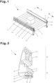
- Fig. 7 shows the sensor holder 11 in a perspective view, wherein the connection arrangement 12 is arranged on a bottom side of the sensor holder 11.
- the sensor holder 11 can thus be fixed by the connection arrangement 12 on the mounting leg 7 of the frame profile 3a, 3b.
- a fastening process takes place as previously described and in Fig. 3a and Fig. 3b shown.
- connection arrangement 12 provides an outer housing 29 of the sensor holder 11.
- An inner housing 30 is arranged within the outer housing 29, in which the sensor 10 is positioned.
- the inner housing 30 is pivotally mounted on the outer housing 29.
- the first side wall 16 and the second side wall 16 of the connection arrangement 12 or the outer housing 29 each have a bolt receptacle 31.
- the bolt receptacle 31 comprises a through hole for receiving a bolt and a guide notch in which the bolt can be guided to the through hole.
- a bolt is formed on each of the opposite side walls of the inner housing 30, which bolt engages in a respective bolt receptacle 31.
- the bolts are aligned in a line with one another, so that they define a pivot axis of the inner housing 30, which is aligned parallel to the bottom wall 14.
- the connecting element 18 of the connection arrangement 12 has a cable channel through which a sensor cable 32 can be guided out of the outer housing 29.
- the cable channel extends through the connecting element 18 and through the base wall 14 and is cylindrical. So that the sensor cable 32 can be pushed laterally into the cable channel, the cable channel is open at the side or is C-shaped in cross section. Since the cable channel extends through the connecting element 18, it is possible to guide the sensor cable 32 through the first recess 8 of the recesses 8 into the interior of the frame profile 3a, 3b.
- the base body Due to lower loads on the sensor holder 11 than on the side guide holder 6, it is not necessary for the base body to have several supporting walls and/or the connecting element 18 to have a stiffening element 19.
- the sensor holder 11 In order to adjust an inclination of the inner housing 30 and thus of the sensor 10 accommodated therein relative to the conveying plane FE, the sensor holder 11 has an adjustment device which is accessible and operable via an actuating opening 33 in the ceiling wall 15 and/or in the bottom wall 14.
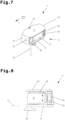
- Fig. 8 shows a cross section along the Fig. 7 shown line VIII-VIII through the sensor holder 11, whereby the adjustment device can be seen within the outer housing 29.
- the adjustment device comprises an adjusting screw 34 and a toothing 35 that interacts with it and is arranged on the inner housing 30.
- the adjusting screw 34 is aligned orthogonally to the bottom wall 14 and the toothing 35 is curved around the pivot axis of the inner housing 30.
- the adjusting screw 34 can be operated through the actuation opening 33 in the top wall 15, for example with a screwdriver.
- Fig. 9 shows a cross section through the conveyor device 1 along the line IX-IX in Fig. 1 .
- the sensor holder 11 is attached to the mounting leg 7 of the second frame profile 3b, so that the outer housing 29 is positioned essentially between the second frame profile 3b and the second side guide profile 4b.
- the sensor holder 11 can be attached to the first frame profile 3a in an analogous manner.
- the side guide profile 4a, 4b is, as in Fig. 5 , arranged so that a vertical distance is provided between the mounting leg 7 and a lower edge of the side guide profile 4a, 4b or a tangential plane through the lower edge of the side guide profile 4a, 4b.
- the vertical distance enables an optical connection of the sensor 10 to the conveying area.
- a perspective view of a cover holder 36 is shown, with which a cover 37, in particular a bottom cover for the conveyor device 1, can be fixed to the frame profile 3a, 3b.
- the cover holder 36 has a further embodiment of the connection arrangement 12.
- the mounting receptacle 13 comprises a connecting means 22, which is designed as a hammer head screw.
- the base body has a bottom wall 14 on which the connecting element 18 is arranged.
- the connecting element 18 is designed analogously to the previously shown embodiments of the connection arrangement 12.
- the stiffening element 19 is not absolutely necessary for the cover holder 36.
- the locking device comprises a recess in the bottom wall 14.
- the locking element 21 is arranged in the recess so that it can be moved orthogonally to the bottom wall 14, so that the locking element 21 can be moved out of the recess.
- the locking element 21 is mounted so that it can rotate about a locking axis. The locking axis of rotation is aligned orthogonally to the bottom wall 14. It is provided that the locking element 21 is flush with the bottom wall 14 or is arranged so as to be set back from the bottom wall 14 when the locking element 21 is positioned within the recess.
- Fig. 10b shows the connection arrangement 12 from Fig. 10a wherein the locking element 21 is moved out of the recess and rotated by 90°.
- the locking element 21 is designed with a hammer-shaped head, as previously described for the connecting element 18.
- the mounting bracket 13 and the base body of the Fig. 10a and Fig. 10b are rigidly connected or formed in one piece.
- Fig. 10c an alternative embodiment of the cover holder 36 is shown, in which the mounting receptacle 13 and the base body are pivotably connected to one another, in particular via a hinge.
- the cover 37 can be pivotally attached to the frame profile 3a, 3b.
- connection arrangement 12 or the cover holder 36 is attached to a mounting leg 7 essentially as in Fig. 3a and Fig. 3b shown and described previously.
- the cover bracket 36 or the connection arrangement 12 is first, as in Fig. 3a shown, brought into the connection position 24, in which the head of the connecting element 18 is guided through the first recess 8 of the recesses 8 of the mounting leg 7.
- the connection arrangement 12 is then rotated by the angle of rotation ⁇ into the mounting position 25.
- the locking element 21 can now be moved out of the recess and, analogously to the connecting element 18, brought into engagement with the second recess 8 of the recesses 8. In this case, a head of the locking element 21 is guided through the second recess 8 of the recesses 8.
- the locking element 21 can then be rotated, in particular by 90°, so that the hammer-shaped head of the locking element 21 engages behind the mounting leg 7 in an edge region of the second recess 8 in the same way as the head of the connecting element 18. This is shown in Fig. 11 shown.
- the mounting leg 7 is arranged on a cover 37.
- a first edge section of the cover 37 and a second edge section of the cover 37 each form a mounting leg 7.
- the cover 37 can be designed, for example, as a bottom cover of a conveyor device 1, which is attached to the other leg or to a cover leg of the frame profile 3a, 3b via the cover holder 36.
- Fig. 12a shows a cross section through the cover holder 36, with which the cover 37 is attached to the frame profile 3a, 3b.
- the cover 37 or the mounting leg 7 of the cover 37 is attached to the cover holder 36 by means of the connection arrangement 12.
- the connecting means 22 of the cover holder 36 is inserted into the fastening groove 27a on the other leg or on the cover leg of the frame profile 3a, 3b and cooperates with it to attach the cover holder 36 to the frame profile 3a, 3b.
- Fig. 12b a further cross-section through the cover holder 36 is shown in a plane through the locking element 21, which is rotatably and displaceably mounted on the base body of the connection arrangement 12.
- Fig. 13a a section of an alternative embodiment of the conveyor device 1 is shown in perspective.
- the conveyor device 1 is essentially analogous to the one shown in Fig. 1 shown conveyor device 1 is constructed.
- a first frame profile 3a and a second frame profile 3b run parallel to each other at a mutual distance in a conveying direction of the (not registered) piece goods 2.
- a plurality of conveying elements 5 are arranged, which define a conveying plane FE.
- the conveyor elements 5 are designed as conveyor rollers.
- the conveyor elements 5 are designed as conveyor belts or that a conveyor element 5 is provided which is designed as a conveyor belt.
- a conveyor belt can also be guided around conveyor rollers so that the conveyor element 5 is formed by the conveyor belt.
- the piece goods 2 are transported on the conveying level FE or in a conveying area which is limited laterally by the side guide profiles 4a, 4b or by mutually facing inner or guide sides of the side guide profiles 4a, 4b and downwards by the conveying level FE.
- a first side guide profile 4a and a second side guide profile 4b also run at a mutual distance parallel to each other and in the conveying direction of the piece goods 2.
- the first side guide profile 4a is mounted on the first frame profile 3a and the second side guide profile 4b on the second frame profile 3b.
- the side guide profiles 4a, 4b are each attached to the corresponding frame profile 3a, 3b by means of side guide brackets.
- the side guide profiles 4a, 4b are mounted via side guide brackets 6' which are alternative to the side guide brackets described above and which are attached to the side of the frame profile 3a, 3b. In principle, however, it would also be conceivable to use side guide brackets with the connection arrangement 12 described above.
- side guide profiles 4a, 4b are provided, which essentially connect directly to the respective frame profile 3a, 3b. This makes the conveyor device 1 suitable for the transport of piece goods 2, which are packed in so-called polybags.
- the side guide profiles 4a, 4b each have a guide side and a mounting side.
- the side guide profiles 4a, 4b are arranged so that their guide sides face each other or the conveyor area.
- the mounting side of the first side guide profile 4a and the mounting side of the second side guide profile 4b face away from each other or the conveyor area.
- the side guide profiles 4a, 4b are each connected to the side guide brackets 6' on the mounting side.
- the frame profiles 3a, 3b essentially have a C-shaped cross-section, with a side cover 9 for closing or covering an open side of the C-shaped cross-section.
- an interior of the frame profile 3a, 3b is provided which is delimited by the frame profile 3a, 3b and the side cover 9.
- Fig. 13 the first frame profile 3a is shown with the side cover 9 and the second frame profile 3b is shown without the side cover 9.
- the frame profiles 3a, 3b each have a mounting leg 7 which comprises a plurality of recesses 8 arranged at a distance from one another, as described above.
- the conveyor device 1 has one or more light barriers, in particular reflection light barriers. Two light barriers are arranged in the section of the conveyor device 1 shown. Of course, further light barriers and/or additional sensors 10 can be arranged in sections not shown.
- Such a light barrier comprises a sensor 10 and a light reflector corresponding to the sensor 10, which in Fig. 13 is not shown.
- the sensor 10 is attached to the first frame profile 3a.
- the light reflector is mounted opposite the sensor 10 on the second frame profile 3b or on the second side guide profile 4b.
- a (not visible) sensor 10 of a first light barrier is attached by means of a first sensor holder 11, which has a previously described connection arrangement 12.
- a sensor 10 shown of a second light barrier is mounted by means of an alternative sensor holder 11a, which is attached laterally to the frame profile 3a, 3b.
- sensors 10 can be mounted either by means of the first sensor holder 11 or the alternative sensor holder 11a.
- the (not visible) sensor 10 can be mounted by means of a further alternative sensor holder 11b, which is attached to the first side guide profile 4a.
- the further alternative sensor holder 11b has an outer housing 29 and an inner housing 30 for receiving the sensor 10, as in Fig. 7 and Fig. 8 shown.
- the inner housing 30 is (as previously Fig. 7 and Fig. 8 described) is pivotably mounted on the outer housing 29.
- An inclination of the inner housing 30 or the sensor 10 can be adjusted by means of a previously Fig. 7 and Fig. 8 In contrast to the adjustment device described in Fig.8
- the version shown in Fig. 13b The outer housing 29 shown has no connecting element 18 and no locking element 21.
- the sensor holder 11b comprises an alternative connection arrangement with a fastening means or clamping means, which is connected to the Fig. 14 upper fastening groove 27b or the lower fastening groove 27b ⁇ , as shown in Fig. 13b shown.
- the alternative connection arrangement can be designed essentially analogously to the mounting section 13 of the side guide bracket 6.
- the sensor 10 comprises a light source or a light transmitter for providing a emitted light beam (see arrow in full line in Fig. 14 ) and a light receiver for detecting a light beam.
- the emitted light beam is guided from the light source to the light reflector, whereby the emitted light beam passes through the conveying area.
- a light beam reflected at the light reflector is guided from the light reflector to the light receiver, whereby the reflected light beam passes through the conveying area.
- the first lateral guide profile 4a has a first through-opening 38 and the second lateral guide profile 4b has a second through-opening 38, which provide a pinhole on the sensor side and a pinhole on the reflector side. It is provided that each sensor 10 and/or each reflector is assigned a pinhole of the pinholes.
- the senor 10 can be adjusted relative to the sensor-side pinhole via an adjustment device, so that an angle between a central axis of the through-opening 38 and the emitted light beam can be set. It is also provided that the sensor 10 is positioned relative to the through-opening 38, so that part of the light beam is cut off by the through-opening 38. In this case, the light beam runs offset from the central axis of the through-opening 38.
- the light reflector can be adjusted in the same way, so that an angle between a central axis of the second through-opening 38 and the reflected light beam can be set.
- Fig. 14 is a cross-section through the first side guide profile 4a and schematically indicated the first frame profile 3a of the alternative conveyor device 1, which has a first or upper fastening groove 27b and a second or lower fastening groove 27b ⁇ .
- the first side guide profile 4a thus has a, in comparison to the in Fig. 5 and Fig. 9
- the side guide profile 4a has a greater height or a greater distance between a lower edge and an upper edge of the side guide profile 4a than the side guide profile shown in cross section. This allows a gap or vertical distance between the side guide profile 4a and the frame profile 3a, 3b to be closed or reduced.
- the second side guide profile 4b can be designed in the same way and arranged analogously on the second frame profile 3b.
- the side guide profiles 4a, 4b can be arranged such that a lower edge of the respective side guide profile 4a, 4b runs below the conveying plane FE, as in Fig. 14
- the conveying plane FE can extend, in particular slightly, above a lower edge of the side guide profile 4a, 4b, as in Fig. 14 registered.
- the side guide bracket 6' engages in the upper fastening groove 27b, as shown in Fig. 13
- the side guide profile 4a, 4b has an apron 39 to form a gap or vertical distance between the side guide profile 4a, 4b and the frame profile 3a, 3b, as shown in Fig. 1 is visible, as in Fig. 14 is shown.
- the through opening 38 is arranged in the apron 39 in order to guide the emitted light beam and/or the reflected light beam into the conveying area just above the conveying plane FE.
- the through opening 38 or the aperture plate can be drilled or punched.
- connection arrangement 12 a robust and lockable connection device can be realized, with which various holders for conveyor device components, such as side guide profiles 4a, 4b, connecting elements 18, sensors 10, reflectors, covers 37, in particular underside covers, and the like, can be attached to the frame profile 3a, 3b of the conveyor device 1.
- Such holders can therefore be designed, for example, as side guide holders 6, sensor holders 11 and cover holders 36.
- the connecting device according to the invention can thus be used universally and in a simple manner and simplifies the assembly work on the conveyor device 1. Furthermore By means of the through opening 38, an area of application of the conveying device 1 can be expanded.
- the devices shown may in reality comprise more or fewer components than shown. In some cases, the devices shown or their components may also be shown not to scale and/or enlarged and/or reduced in size.
Landscapes
- Engineering & Computer Science (AREA)
- Mechanical Engineering (AREA)
- General Engineering & Computer Science (AREA)
- Connection Of Plates (AREA)
- Framework For Endless Conveyors (AREA)
- Control Of Conveyors (AREA)
Applications Claiming Priority (3)
| Application Number | Priority Date | Filing Date | Title |
|---|---|---|---|
| ATA50466/2020A AT523860B1 (de) | 2020-05-28 | 2020-05-28 | Verbindungsvorrichtung zur Montage einer Halterung für Komponenten einer Fördervorrichtung und Fördervorrichtung zum Transport von Stückgut |
| PCT/AT2021/060182 WO2021237262A1 (fr) | 2020-05-28 | 2021-05-27 | Dispositif de raccord pour l'assemblage d'un support de composants de dispositif de transport, et dispositif de transport servant au transport de charges unitaires |
| EP21732169.4A EP4157760B1 (fr) | 2020-05-28 | 2021-05-27 | Dispositif de raccord pour l'assemblage d'un support de composants de dispositif de transport, et dispositif de transport servant au transport de charges unitaires |
Related Parent Applications (2)
| Application Number | Title | Priority Date | Filing Date |
|---|---|---|---|
| EP21732169.4A Division EP4157760B1 (fr) | 2020-05-28 | 2021-05-27 | Dispositif de raccord pour l'assemblage d'un support de composants de dispositif de transport, et dispositif de transport servant au transport de charges unitaires |
| EP21732169.4A Division-Into EP4157760B1 (fr) | 2020-05-28 | 2021-05-27 | Dispositif de raccord pour l'assemblage d'un support de composants de dispositif de transport, et dispositif de transport servant au transport de charges unitaires |
Publications (2)
| Publication Number | Publication Date |
|---|---|
| EP4446259A2 true EP4446259A2 (fr) | 2024-10-16 |
| EP4446259A3 EP4446259A3 (fr) | 2024-12-04 |
Family
ID=76444174
Family Applications (3)
| Application Number | Title | Priority Date | Filing Date |
|---|---|---|---|
| EP24197261.1A Pending EP4446599A3 (fr) | 2020-05-28 | 2021-05-27 | Dispositif de transport pour le transport de marchandises au détail |
| EP24197270.2A Pending EP4446259A3 (fr) | 2020-05-28 | 2021-05-27 | Dispositif de liaison pour le montage d'un support pour composants d'un dispositif de transport et dispositif de transport pour le transport de marchandises |
| EP21732169.4A Active EP4157760B1 (fr) | 2020-05-28 | 2021-05-27 | Dispositif de raccord pour l'assemblage d'un support de composants de dispositif de transport, et dispositif de transport servant au transport de charges unitaires |
Family Applications Before (1)
| Application Number | Title | Priority Date | Filing Date |
|---|---|---|---|
| EP24197261.1A Pending EP4446599A3 (fr) | 2020-05-28 | 2021-05-27 | Dispositif de transport pour le transport de marchandises au détail |
Family Applications After (1)
| Application Number | Title | Priority Date | Filing Date |
|---|---|---|---|
| EP21732169.4A Active EP4157760B1 (fr) | 2020-05-28 | 2021-05-27 | Dispositif de raccord pour l'assemblage d'un support de composants de dispositif de transport, et dispositif de transport servant au transport de charges unitaires |
Country Status (8)
| Country | Link |
|---|---|
| US (1) | US20230211958A1 (fr) |
| EP (3) | EP4446599A3 (fr) |
| KR (1) | KR20230017285A (fr) |
| CN (1) | CN115667104B (fr) |
| AT (1) | AT523860B1 (fr) |
| CA (1) | CA3184446A1 (fr) |
| ES (1) | ES2999286T3 (fr) |
| WO (1) | WO2021237262A1 (fr) |
Families Citing this family (2)
| Publication number | Priority date | Publication date | Assignee | Title |
|---|---|---|---|---|
| EP4269290B1 (fr) * | 2022-04-25 | 2025-09-17 | Grob-Werke GmbH & Co. KG | Porte-pièce |
| US12545522B2 (en) * | 2024-01-30 | 2026-02-10 | Intelligrated Headquarters, Llc | Conveyor assembly |
Citations (5)
| Publication number | Priority date | Publication date | Assignee | Title |
|---|---|---|---|---|
| EP0995980A2 (fr) | 1998-10-20 | 2000-04-26 | Hitachi, Ltd. | Structure de montage d'un capteur et capteur semi-conducteur de pression pour véhicules à moteur |
| DE10118566A1 (de) | 2001-04-14 | 2002-10-17 | Bosch Gmbh Robert | Haltevorrichtung für eine Seitenführung eines Stetigförderers |
| US6588578B1 (en) | 2002-02-20 | 2003-07-08 | Alvey Syst Inc | Conveyor guiderail snag resistant opening |
| EP1661754A2 (fr) | 2004-11-24 | 2006-05-31 | Böllhoff Verbindungstechnik GmbH | Elément de fixation pour attacher un object à un support |
| EP2103555A1 (fr) | 2008-02-28 | 2009-09-23 | Société d'étude et de développement de la Productique | Convoyeur équipé de supports pour le montage d' éléments tels qu'un rail de guidage latéral de charges |
Family Cites Families (9)
| Publication number | Priority date | Publication date | Assignee | Title |
|---|---|---|---|---|
| DE4308982C2 (de) * | 1993-03-20 | 1994-12-15 | Mtf Technik Ing Grad Hans Gert | Förderband |
| JPH08188213A (ja) * | 1995-01-04 | 1996-07-23 | Toyo Kanetsu Kk | コンベヤフレーム |
| JP3871387B2 (ja) * | 1996-11-20 | 2007-01-24 | 極東開発工業株式会社 | 受光センサ用のクリーニング装置 |
| DE602004003335T2 (de) * | 2003-01-24 | 2007-07-05 | Dematic Corp., Grand Rapids | Integriertes fördereinrichtungsbett |
| US7039089B2 (en) * | 2003-12-02 | 2006-05-02 | Trimble Navigation Limited | Interchangeable horizontally and vertically laser suitable for use in small spaces |
| CN104075167A (zh) * | 2013-03-28 | 2014-10-01 | 欧司朗有限公司 | 照明装置 |
| JP6410013B2 (ja) * | 2014-04-23 | 2018-10-24 | シブヤ精機株式会社 | 物品選別装置 |
| JP6555139B2 (ja) * | 2016-01-19 | 2019-08-07 | 横浜ゴム株式会社 | コンベヤベルトの検査装置 |
| US11702294B2 (en) * | 2020-03-30 | 2023-07-18 | Flexlink Ab | Conveyor guide rail attachment |
-
2020
- 2020-05-28 AT ATA50466/2020A patent/AT523860B1/de active
-
2021
- 2021-05-27 KR KR1020227045942A patent/KR20230017285A/ko not_active Withdrawn
- 2021-05-27 US US17/927,090 patent/US20230211958A1/en active Pending
- 2021-05-27 CN CN202180038488.5A patent/CN115667104B/zh active Active
- 2021-05-27 EP EP24197261.1A patent/EP4446599A3/fr active Pending
- 2021-05-27 CA CA3184446A patent/CA3184446A1/fr active Pending
- 2021-05-27 EP EP24197270.2A patent/EP4446259A3/fr active Pending
- 2021-05-27 ES ES21732169T patent/ES2999286T3/es active Active
- 2021-05-27 EP EP21732169.4A patent/EP4157760B1/fr active Active
- 2021-05-27 WO PCT/AT2021/060182 patent/WO2021237262A1/fr not_active Ceased
Patent Citations (5)
| Publication number | Priority date | Publication date | Assignee | Title |
|---|---|---|---|---|
| EP0995980A2 (fr) | 1998-10-20 | 2000-04-26 | Hitachi, Ltd. | Structure de montage d'un capteur et capteur semi-conducteur de pression pour véhicules à moteur |
| DE10118566A1 (de) | 2001-04-14 | 2002-10-17 | Bosch Gmbh Robert | Haltevorrichtung für eine Seitenführung eines Stetigförderers |
| US6588578B1 (en) | 2002-02-20 | 2003-07-08 | Alvey Syst Inc | Conveyor guiderail snag resistant opening |
| EP1661754A2 (fr) | 2004-11-24 | 2006-05-31 | Böllhoff Verbindungstechnik GmbH | Elément de fixation pour attacher un object à un support |
| EP2103555A1 (fr) | 2008-02-28 | 2009-09-23 | Société d'étude et de développement de la Productique | Convoyeur équipé de supports pour le montage d' éléments tels qu'un rail de guidage latéral de charges |
Also Published As
| Publication number | Publication date |
|---|---|
| WO2021237262A1 (fr) | 2021-12-02 |
| EP4446259A3 (fr) | 2024-12-04 |
| CN115667104B (zh) | 2025-05-27 |
| CA3184446A1 (fr) | 2021-12-02 |
| AT523860B1 (de) | 2023-06-15 |
| EP4157760B1 (fr) | 2024-10-02 |
| EP4446599A2 (fr) | 2024-10-16 |
| CN115667104A (zh) | 2023-01-31 |
| EP4446599A3 (fr) | 2024-12-04 |
| US20230211958A1 (en) | 2023-07-06 |
| ES2999286T3 (en) | 2025-02-25 |
| AT523860A1 (de) | 2021-12-15 |
| EP4157760A1 (fr) | 2023-04-05 |
| KR20230017285A (ko) | 2023-02-03 |
| EP4157760C0 (fr) | 2024-10-02 |
Similar Documents
| Publication | Publication Date | Title |
|---|---|---|
| EP2661194B1 (fr) | Dispositif pour ajuster le front d'un tiroir | |
| DE69803296T2 (de) | Halterung für eine abschirmvorrichtung | |
| WO2011079400A1 (fr) | Agencement de mécanisme de roulement comprenant un rail de guidage pour porte coulissante | |
| EP2873792A1 (fr) | Penture | |
| EP4157760B1 (fr) | Dispositif de raccord pour l'assemblage d'un support de composants de dispositif de transport, et dispositif de transport servant au transport de charges unitaires | |
| DE202022002815U1 (de) | Verbesserte Inspektionsklappe | |
| DE10156992A1 (de) | Trittelementbefestigung für Personenbeförderer | |
| EP1002923A2 (fr) | Dispositif d'ouverture et de fermeture d'une ouverture dans une paroi au moyen d'une porte coulissante | |
| EP2163497B1 (fr) | Transporteur à rouleaux | |
| DE102004003861B4 (de) | Vorrichtung zur lösbaren Halterung von einem Flächenelement, ein System mit wenigstens zwei solcher Vorrichtungen und deren Verwendung | |
| DE3141158C2 (de) | Führungsvorrichtung für einen ein- und ausfahrbaren Einsatz im Korpus eines Schrankes | |
| EP3721100B1 (fr) | Ensemble de liaison | |
| EP1249406A1 (fr) | Dispositif de renvoi pour convoyeur | |
| EP3266970A1 (fr) | Charnière et porte comprenant au moins une charnière | |
| DE19702863A1 (de) | Scharnier für ein Flügelteil, insbesondere einen Tür- oder Fensterflügel | |
| EP1875834B1 (fr) | Dispositif de retenue pour une tringle et un meuble | |
| EP3666120B1 (fr) | Dispositif de raccordement de l'avant de tiroir et tiroir | |
| EP4066802A1 (fr) | Plate-forme pour appareils ou équipements médicaux pourvue d'éléments crochets réglables | |
| AT502259B1 (de) | Vorrichtung zum halten von in schienen geführten laufwerken | |
| EP4146888A1 (fr) | Ensemble charnière à actionnement commun | |
| EP3379013B1 (fr) | Dispositif de guidage réglable pour un élément coulissant | |
| EP3138764A1 (fr) | Dispositif de fixation de bagage et moto le comprenant | |
| EP0735217A2 (fr) | Gâche pour pêne de portes ou fenêtres | |
| EP1447032B1 (fr) | Comptoir d'enregistrement pour marchandises | |
| DE2404812B2 (de) | Schieberlueftung, insbesondere fuer eine tuere, ein fenster o.dgl. |
Legal Events
| Date | Code | Title | Description |
|---|---|---|---|
| PUAI | Public reference made under article 153(3) epc to a published international application that has entered the european phase |
Free format text: ORIGINAL CODE: 0009012 |
|
| STAA | Information on the status of an ep patent application or granted ep patent |
Free format text: STATUS: THE APPLICATION HAS BEEN PUBLISHED |
|
| AC | Divisional application: reference to earlier application |
Ref document number: 4157760 Country of ref document: EP Kind code of ref document: P |
|
| AK | Designated contracting states |
Kind code of ref document: A2 Designated state(s): AL AT BE BG CH CY CZ DE DK EE ES FI FR GB GR HR HU IE IS IT LI LT LU LV MC MK MT NL NO PL PT RO RS SE SI SK SM TR |
|
| PUAL | Search report despatched |
Free format text: ORIGINAL CODE: 0009013 |
|
| AK | Designated contracting states |
Kind code of ref document: A3 Designated state(s): AL AT BE BG CH CY CZ DE DK EE ES FI FR GB GR HR HU IE IS IT LI LT LU LV MC MK MT NL NO PL PT RO RS SE SI SK SM TR |
|
| RIC1 | Information provided on ipc code assigned before grant |
Ipc: F16B 21/04 20060101ALI20241029BHEP Ipc: B65G 13/11 20060101ALI20241029BHEP Ipc: B65G 21/20 20060101ALI20241029BHEP Ipc: B65G 21/06 20060101AFI20241029BHEP |
|
| RAP3 | Party data changed (applicant data changed or rights of an application transferred) |
Owner name: TGW IMMOBILIEN WELS GMBH |
|
| RAP1 | Party data changed (applicant data changed or rights of an application transferred) |
Owner name: TGW LOGISTICS GMBH |
|
| STAA | Information on the status of an ep patent application or granted ep patent |
Free format text: STATUS: REQUEST FOR EXAMINATION WAS MADE |
|
| 17P | Request for examination filed |
Effective date: 20250604 |
|
| STAA | Information on the status of an ep patent application or granted ep patent |
Free format text: STATUS: EXAMINATION IS IN PROGRESS |
|
| 17Q | First examination report despatched |
Effective date: 20251017 |