EP4484328A1 - Verschlusssystem für einen flexiblen beutel für einen vollständig an der flexiblen tasche befestigten stringer - Google Patents
Verschlusssystem für einen flexiblen beutel für einen vollständig an der flexiblen tasche befestigten stringer Download PDFInfo
- Publication number
- EP4484328A1 EP4484328A1 EP24178491.7A EP24178491A EP4484328A1 EP 4484328 A1 EP4484328 A1 EP 4484328A1 EP 24178491 A EP24178491 A EP 24178491A EP 4484328 A1 EP4484328 A1 EP 4484328A1
- Authority
- EP
- European Patent Office
- Prior art keywords
- cylindrical
- rib
- cylindrical tube
- external
- pipe
- Prior art date
- Legal status (The legal status is an assumption and is not a legal conclusion. Google has not performed a legal analysis and makes no representation as to the accuracy of the status listed.)
- Pending
Links
Images


Classifications
-
- B—PERFORMING OPERATIONS; TRANSPORTING
- B65—CONVEYING; PACKING; STORING; HANDLING THIN OR FILAMENTARY MATERIAL
- B65D—CONTAINERS FOR STORAGE OR TRANSPORT OF ARTICLES OR MATERIALS, e.g. BAGS, BARRELS, BOTTLES, BOXES, CANS, CARTONS, CRATES, DRUMS, JARS, TANKS, HOPPERS, FORWARDING CONTAINERS; ACCESSORIES, CLOSURES, OR FITTINGS THEREFOR; PACKAGING ELEMENTS; PACKAGES
- B65D75/00—Packages comprising articles or materials partially or wholly enclosed in strips, sheets, blanks, tubes or webs of flexible sheet material, e.g. in folded wrappers
- B65D75/52—Details
- B65D75/58—Opening or contents-removing devices added or incorporated during package manufacture
- B65D75/5861—Spouts
- B65D75/5872—Non-integral spouts
- B65D75/5883—Non-integral spouts connected to the package at the sealed junction of two package walls
Definitions
- the present invention relates to a closure system for a flexible bag intended to remain attached to the flexible bag.
- Flexible pouches are generally used to contain food or non-food fluid materials.
- a fluid material may correspond to a liquid material (beverage, windshield washer fluid, etc.), a pasty material (toothpaste, etc.) or a granular material (sand, sugar, etc.)
- capping devices that remain attached to the flexible bag.
- the cap is usually attached to the flexible bag by a tether.
- the cap therefore has no fixed position relative to the flexible bag, which may hinder the user who attempts to pour the flowable material or to suck up the flowable material.
- the document US 2007/012644 and the document KR 2002 0075346 describe closure devices that remain attached to flexible bags. Existing closure devices are therefore not completely satisfactory.
- the object of the present invention is to propose a closure system for a flexible bag intended to remain completely attached to the flexible bag.
- the first external rib and the internal rib being further configured so that the first external rib is able to pass over the internal rib during the first insertion of the cylindrical tube at least partially into the cylindrical space.
- the internal rib has a first circular surface orthogonal to the internal surface of the second cylindrical pipe, the first circular surface facing the second end of the second cylindrical pipe; the first external rib having a second circular surface orthogonal to the external surface of the cylindrical tube on the second section, the second circular surface facing the first end of the cylindrical tube; the second circular surface being capable of being pressed against the first circular surface when the first external rib abuts against the internal rib, preventing the passage of the first external rib over the internal rib.
- the cylindrical tube comprises a second external rib projecting from the external surface of the cylindrical tube on the first section, the second external rib being configured to temporarily block a sliding of the cylindrical tube when the second external rib bears against the internal rib towards the second end of the first cylindrical conduit when the cylindrical tube is in the first blocking position.
- the second outer rib has a rounded surface.
- the cylindrical tube comprises a third external rib projecting from the external surface of the cylindrical tube on the second section, the third external rib being configured to temporarily block a sliding of the cylindrical tube towards the first end of the first cylindrical conduit when the third external rib bears against the internal rib and when the internal rib is located between the first external rib (15) and the third external rib.
- the second cylindrical pipe comprises at least one relief projecting on its internal surface, the relief(s) extending parallel to the third axis of revolution, the relief(s) being in mechanical connection with friction with the cylindrical tube such that the cylindrical tube is able to slide around the first cylindrical pipe along the second axis of revolution if a user exerts a force parallel to the second axis of revolution on the cylindrical tube which is greater than a predetermined force.
- the first cylindrical pipe has an external surface, the first cylindrical pipe comprising at least one relief projecting on its external surface, the relief(s) extending parallel to the first axis of revolution, the relief(s) being in mechanical connection with friction with the cylindrical tube such that the cylindrical tube is able to slide around the first cylindrical pipe along the second axis of revolution. revolution if a user exerts a force parallel to the second axis of revolution on the cylindrical tube that is greater than a predetermined force.
- the first cylindrical conduit has an internal surface comprising an obstacle projecting from said internal surface inside the first cylindrical conduit.
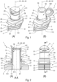
- the closure system 1 is shown in the figure 1 to the figure 3 , on the figure 7 and the figure 8 .
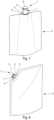
- the closure system 1 is intended to be fixed to an opening 3 of a flexible bag 2 capable of containing a fluid material ( figure 7 and figure 8 ).
- the capping system 1 comprises a pouring device 4 and a stopper device 7.
- the pouring device 4 ( figure 5 ) comprises a fixing part 5 and a first cylindrical pipe 6.
- the fixing part 5 is intended to fix the closure system 1 to the opening 3 of the flexible bag 2.
- the first cylindrical pipe 6 is intended to form a passage of the fluid material between the inside of the flexible bag 2 and the outside of the flexible bag 2.
- the first cylindrical pipe 6 has a first end 61, a second end 62 and a first axis of revolution A1.
- the first cylindrical pipe 6 has an internal surface S6.
- the first cylindrical pipe 6 is integral from the fixing part 5 to the first end 61 of the first cylindrical pipe 6.
- An "internal surface” for a hollow cylinder (such as a pipe or tube) is defined as a surface of said hollow cylinder directed toward its axis of revolution.
- an “external surface” for a hollow cylinder is defined as a surface of said hollow cylinder directed away from its axis of revolution.
- the fixing part 5 and the first cylindrical pipe 6 are in one piece.
- the fixing part 5 may correspond to a so-called boat-shaped fixing.
- This boat-shaped fixing comprises a plurality of planes 23 perpendicular to the first axis of revolution A1.
- Each perpendicular plane has a substantially rhomboidal shape surrounding at least the first cylindrical pipe 6.
- the center of the rhomboidal shape of each parallel plane coincides with the first axis of revolution A1.
- Each parallel plane has an edge intended to be fixed, for example by welding, to the opening of the flexible bag 2.
- the stopper device 7 ( figure 6 ) comprises a stopper 8 and a cylindrical tube 9.
- the plug 8 is configured to be alternately in a closed position in which the plug 8 plugs the second end 62 of the first cylindrical conduit 6 and in an open position in which the plug 8 does not plug the second end 62 of the first cylindrical conduit 6. When the plug is in the open position, the fluid material contained in the flexible bag 2 can exit through the first cylindrical conduit 6.
- the locking positions of the cylindrical tube 9 correspond to extreme positions or limits limiting the sliding of the cylindrical tube 9 around the first cylindrical pipe 6 along the second axis of revolution A2.
- the stopper 8 and the cylindrical tube 9 provide hygienic use of the stopper system 1.
- the cylindrical tube 9 and the cap 8 isolate the first cylindrical conduit 6 from external elements.
- the cylindrical tube 9 and the cap 8 make it possible to keep the first cylindrical conduit 6 clean.
- the user may be required to put his mouth around the first cylindrical conduit 6.
- the cap 8 and the cylindrical tube 6 therefore make it possible to protect the part of the first cylindrical conduit 6 intended to receive the user's mouth.
- the cylindrical tube 9 and the cap 8 also make it possible to protect the elements from the fluid material that could have been deposited on the external surface of the first cylindrical conduit 6.
- the plug 8 corresponds to a screw cap.
- the second end 62 of the first cylindrical pipe 6 comprises a thread configured to cooperate with a thread arranged in the plug 8.
- the first locking position may be located a predetermined distance further from the position of the cylindrical tube when the plug is in the closed position in the direction going from the first end 61 to the second end 62 of the first cylindrical pipe.
- the predetermined distance corresponds substantially to the distance necessary for the displacement of the plug 8, in the direction going from the first end 61 to the second end 62 of the first cylindrical pipe, during an unscrewing of the plug 8 from the first cylindrical pipe 6.
- the plug 8 can comprise at least one breakable bridge having the same function as the bridge(s) described in the first embodiment of the plug 8.
- the stopper 8, the cylindrical tube 9 and the hinge 10 are in one piece.
- the bridge(s) 24 may also be in one piece with the stopper 8, the cylindrical tube 9 and the hinge 10.
- the pouring device 4 can also comprise a second cylindrical pipe 11 comprising a first end 111, a second end 112, an internal surface S11 and a third axis of revolution A3 coincident with the first axis of revolution A1 of the first cylindrical pipe 6.
- the first end 111 of the second cylindrical pipe 11 is free.
- the second end 112 comprises the fixing part 4.
- the fixing part 5 corresponds to a boat-shaped fixing.
- Each perpendicular plane 23 is fixed the second cylindrical pipe 11.
- the pouring device 4 may comprise a ring 12 securely connecting the second end 112 of the second cylindrical pipe 11 and the first end 61 of the first cylindrical pipe 6.
- the ring 12 forms a bottom 13 of a cylindrical space 14 between the first cylindrical pipe 6 and the second cylindrical pipe 11.
- the cylindrical tube 9 of the stopper device 7 is then able to slide at least partly in the cylindrical space 14.
- the first locking position may correspond to a position of the cylindrical tube 9 when the second end 92 of the cylindrical tube 9 reaches the bottom 13 of the cylindrical space 14.
- the cylindrical tube 9 has an external surface S9 and comprises a first section T1 and a second section T2.
- the boundary 25 between the two sections T1 and T2 can be located halfway between the first end 91 and the second end 92 of the cylindrical tube 9 ( figure 6 ).
- the first section T1 comprises the first end 91 of the cylindrical tube 9.
- the second section T2 comprises the second end 92 of the cylindrical tube 9.
- the cylindrical tube 9 may comprise a first external rib 15 projecting from the external surface S9 of the cylindrical tube 9 on the second section T2.
- the first end 111 of the second cylindrical conduit 11 may comprise an internal rib 16 projecting from the internal surface S11 of the second cylindrical conduit 11.
- the first external rib 15 is located in the cylindrical space 14 between the bottom 13 and the internal rib 16.
- the first external rib 15 and the internal rib 16 are configured such that the first external rib 15 prevents a passage of the first external rib 15 over the internal rib 16 after a first insertion of the cylindrical tube 9 at least partly into the cylindrical space 14.
- the first insertion may correspond to a step of mounting the stopper device 7 to the pouring device 4 in which the cylindrical tube 9 is mounted around the first cylindrical pipe 6.
- the second locking position may correspond to a position of the cylindrical tube 9 when the first external rib 15 is in abutment against the internal rib 16 to at least partially retain the cylindrical tube 9 in the cylindrical space 14.
- first external rib 15 and the internal rib 16 may also be configured so that the first external rib 15 is able to pass over the internal rib 16 during the first insertion of the cylindrical tube 9 at least partly into the cylindrical space 14.
- the insertion of the cylindrical tube 9 is facilitated during the first insertion.
- the internal rib 16 may have a first circular surface 17 orthogonal to the internal surface S11 of the second cylindrical pipe 11.
- the first circular surface 17 faces the second end 112 of the second cylindrical pipe 11.
- the first external rib 15 may have a second circular surface 18 orthogonal to the external surface S9 of the cylindrical tube 9 on the second section T2.
- the second circular surface 18 faces the first end 91 of the cylindrical tube 9.
- the second circular surface 18 is capable of being pressed against the first circular surface 17 when the first external rib 15 abuts against the internal rib 16, preventing the first external rib 15 from passing over the internal rib 16 when the cylindrical tube 9 slides in the direction indicated by the arrow F2.
- the internal rib 16 may further have a first circular ramp 19 progressing from the first end 111 of the second cylindrical pipe 11 towards the second end 112 of the second circular pipe 11.
- the first external rib 15 may have a second circular ramp 20 progressing from the external surface S9 of the cylindrical tube 9 on the second section T2 towards the first end 91 of the cylindrical tube 9.
- the second circular ramp 20 is capable of sliding against the first circular ramp 19 during the first insertion of the cylindrical tube 9 at least partly into the cylindrical space 14 by allowing the first external rib 15 to pass over the internal rib 16 when the cylindrical tube 9 slides in the direction indicated by the arrow F1.
- the cylindrical tube 9 and/or the second cylindrical conduit 11 may have sufficient elasticity to allow the passage of the first external rib 15 over the internal rib 16.
- the internal rib 16 and/or the first external rib 15 may have sufficient elasticity to allow the passage of the first external rib 15 over the internal rib 16.
- the cylindrical tube 9 may comprise a second external rib 21 projecting from the external surface S9 of the cylindrical tube 9 on the first section T1.
- the second external rib 21 is configured to temporarily block a sliding of the cylindrical tube 9 when the second external rib 21 bears against the internal rib 16 towards the second end 62 of the first cylindrical pipe 6 when the cylindrical tube 9 is in the first blocking position.
- the expression “temporarily blocking a sliding of the cylindrical tube 9” means blocking the sliding of the cylindrical tube 9 if the force allowing this sliding to occur does not reach a predetermined force above which sliding is possible.
- the second external rib 21 has a rounded surface.
- Figures 4C and 4D represents a cross-section of a second external rib 21.
- the rounded surface of the second external rib 21 makes it possible to temporarily block the sliding of the cylindrical tube 9 when the second external rib 21 bears against the internal rib 16 towards the second end 62 of the first cylindrical pipe 6 when the cylindrical tube 9 is in the first blocking position.
- FIG. 4C shows a sliding of the cylindrical tube 9 in the direction indicated by the arrow F3 to bring the cylindrical tube 9 into the first locking position and to temporarily lock the cylindrical tube 9 in the first locking position.
- FIG 4D shows a sliding of the cylindrical tube 9 in the direction indicated by the arrow F4 to remove the cylindrical tube 9 from the first locking position.
- the plug device 7 remains spaced from the second end 62 of the first cylindrical conduit 6. Consequently, the flow of fluid material exiting through the second end 62 of the first cylindrical conduit 6 is not hindered by any obstacle that the plug 8 of the plug device 7 could constitute. Similarly, a user who wishes to bring the second end 62 of the first cylindrical conduit 6 to his mouth is not hindered by the plug device 7. which could slide along the first cylindrical pipe 6 if the cylindrical tube 9 were not retained by the second external rib 21.
- a user wishing to close the flexible bag 2 can bring the cylindrical tube 9 back towards the second end 62 of the first cylindrical conduit 6 by driving the cylindrical tube 9 towards the second end 62 of the first cylindrical conduit 6 with a force greater than the predetermined force allowing the passage of the second external rib 21 over the internal rib 16.
- the user can drive the cylindrical tube 9 by pulling on the cap 8 which is connected to the cylindrical tube 9 by the hinge 10.
- the cylindrical tube 9 may comprise a third external rib 22 projecting from the external surface S9 of the cylindrical tube 9 on the second section T2.
- the third external rib 22 is configured to temporarily block a sliding of the cylindrical tube 9 towards the first end 61 of the first cylindrical pipe 6 when the third external rib 22 bears against the internal rib 16 and when the internal rib 16 is between the first external rib 15 and the third external rib 22.
- the temporary blocking of the sliding of the cylindrical tube 9 by the third rib 22 makes it possible to facilitate the opening of the plug 8 by bringing the plug 8 from the closed position to the open position. Indeed, this temporary blocking makes it possible to maintain the plug device 7 in the first blocking position until the plug 8 is at least 180° from the second end 62 of the first cylindrical pipe 6 around the hinge 10.
- the internal surface S6 may comprise an obstacle (not shown) projecting from said internal surface S6 inside the first cylindrical pipe 6.
- This obstacle makes it possible to limit the flow rate of fluid material leaving the flexible bag 2 via the first cylindrical pipe 6.
- the obstacle may take several forms.
- the obstacle may take the shape of a triangle with a vertex directed towards the first axis of revolution A1.
- the triangular shape may be included in a plane perpendicular to the first axis of revolution A1.
- the second cylindrical conduit 11 may also comprise two slides 27 projecting from the external surface of the second cylindrical conduit 11. ( figure 1 to figure 3 , figure 5 and figure 6 ).
- the 27 wings are not shown on the figure 7 and the figure 8 .
- the slides 27 are arranged at 180° from each other and each have a groove facing in two opposite directions. The grooves of the slides 27 are intended to be received by parallel rails to hold and move the capping system 1 when fixing the capping system 1 to the flexible bag 2.
- the second cylindrical pipe 11 comprises at least one relief 26 projecting from its internal surface S11 ( figure 1 , figure 5 ).
- the relief(s) 26 may each have an elongated shape, such as a rib, which extends parallel to the third axis of revolution A3.
- the second cylindrical pipe 11 may comprise four reliefs 26 arranged at 90° to one another around the third longitudinal axis A3.
- the relief(s) 26 are in mechanical connection with friction with the cylindrical tube 9 such that the cylindrical tube 9 is able to slide around the first cylindrical pipe 6 along the second axis of revolution A2 if a user exerts a force parallel to the second axis of revolution A2 on the cylindrical tube 9 which is greater than a predetermined force.
- the first cylindrical pipe 6 comprises at least one relief (not shown) projecting on its external surface S61.
- the relief(s) may each have an elongated shape, such as a rib, which extends parallel to the first axis of revolution A1.
- the relief(s) are in mechanical connection with friction with the cylindrical tube 9 such that the cylindrical tube 9 is able to slide around the first cylindrical pipe 6 along the second axis of revolution A2 if a user exerts a force parallel to the second axis of revolution A2 on the cylindrical tube 9 which is greater than a predetermined force.
- the mechanical connection with friction makes it possible to avoid untimely sliding of the cylindrical tube 9 between the two locking positions.
- the pouring device 4 and the cap device 7 are each made of plastic material by injection molding technology.
- the plastic material may correspond to polyethylene high density polyethylene (HDPE) or polypropylene (PP).
- the material of the pouring device 4 and the cap device 7 may be of fossil, bio-sourced or biodegradable origin.
- the method of manufacturing the capping system 1 may comprise a step of molding the pouring device 4, a step of molding the cap device 7 and a step of mounting the cap device 7 on the pouring device 4.
- the cylindrical tube 9 is slid onto the first cylindrical pipe 6 so that the first axis of revolution A1 coincides with the second axis of revolution A2 until the first external rib 15 passes above the internal rib 16 and the plug 8 blocks the second end 62 of the first cylindrical pipe 6.
- the cylindrical tube 9 is slid in the direction indicated by the arrow F1 on the Figure 4A .
Landscapes
- Engineering & Computer Science (AREA)
- Mechanical Engineering (AREA)
- Pipe Accessories (AREA)
- Bag Frames (AREA)
Applications Claiming Priority (1)
| Application Number | Priority Date | Filing Date | Title |
|---|---|---|---|
| FR2306730A FR3150508B1 (fr) | 2023-06-27 | 2023-06-27 | Système de bouchage pour poche souple destiné à rester totalement attaché à la poche souple. |
Publications (1)
| Publication Number | Publication Date |
|---|---|
| EP4484328A1 true EP4484328A1 (de) | 2025-01-01 |
Family
ID=88146710
Family Applications (1)
| Application Number | Title | Priority Date | Filing Date |
|---|---|---|---|
| EP24178491.7A Pending EP4484328A1 (de) | 2023-06-27 | 2024-05-28 | Verschlusssystem für einen flexiblen beutel für einen vollständig an der flexiblen tasche befestigten stringer |
Country Status (2)
| Country | Link |
|---|---|
| EP (1) | EP4484328A1 (de) |
| FR (1) | FR3150508B1 (de) |
Citations (5)
| Publication number | Priority date | Publication date | Assignee | Title |
|---|---|---|---|---|
| KR20020075346A (ko) | 2002-08-30 | 2002-10-04 | 이정민 | 배출대 |
| US20040245286A1 (en) * | 2001-09-10 | 2004-12-09 | Lee Jung Min | Spout assembly |
| US20070012644A1 (en) | 2003-03-14 | 2007-01-18 | Seaquest General Plastics | Closure device for a fluid product reservoir |
| EP3148885A1 (de) * | 2014-05-28 | 2017-04-05 | Aptargroup, Inc. | Armatur für einen flexiblen behälter |
| US20200062464A1 (en) * | 2016-12-08 | 2020-02-27 | Fujimori Kogyo Co., Lld. | Coupled structure between pouring spout of refill container and pouring unit of packaging container |
-
2023
- 2023-06-27 FR FR2306730A patent/FR3150508B1/fr active Active
-
2024
- 2024-05-28 EP EP24178491.7A patent/EP4484328A1/de active Pending
Patent Citations (5)
| Publication number | Priority date | Publication date | Assignee | Title |
|---|---|---|---|---|
| US20040245286A1 (en) * | 2001-09-10 | 2004-12-09 | Lee Jung Min | Spout assembly |
| KR20020075346A (ko) | 2002-08-30 | 2002-10-04 | 이정민 | 배출대 |
| US20070012644A1 (en) | 2003-03-14 | 2007-01-18 | Seaquest General Plastics | Closure device for a fluid product reservoir |
| EP3148885A1 (de) * | 2014-05-28 | 2017-04-05 | Aptargroup, Inc. | Armatur für einen flexiblen behälter |
| US20200062464A1 (en) * | 2016-12-08 | 2020-02-27 | Fujimori Kogyo Co., Lld. | Coupled structure between pouring spout of refill container and pouring unit of packaging container |
Also Published As
| Publication number | Publication date |
|---|---|
| FR3150508B1 (fr) | 2025-06-13 |
| FR3150508A1 (fr) | 2025-01-03 |
Similar Documents
| Publication | Publication Date | Title |
|---|---|---|
| EP3741703B1 (de) | Schraubverschluss, der nach seiner öffnung am behälter fixiert bleibt | |
| EP4003866B1 (de) | Sicherheitsverschluss | |
| EP0633197B1 (de) | Kombination von Behälter und Verschluss, die sich durch relative Rotation miteinander verriegeln sowie deren Verwendung | |
| EP3838790B1 (de) | Schraubverschluss, der nach öffnung des behälters an diesem befestigt bleibt | |
| CA3007388C (fr) | Systeme d'obturation pour recipient | |
| EP0468902A1 (de) | Verschlussvorrichtung mit irreversibler Befestigung auf einem Behälterhals | |
| FR3096361A1 (fr) | Bouchon à vis destiné à rester attaché à un récipient après ouverture du récipient. | |
| EP1461263B1 (de) | Verschlussvorrichtung | |
| EP4484328A1 (de) | Verschlusssystem für einen flexiblen beutel für einen vollständig an der flexiblen tasche befestigten stringer | |
| EP0610127B1 (de) | Irreversible abschraubbare Verschlussvorrichtung | |
| EP3984906B1 (de) | Schraubverschluss, der nach dem öffnen an einem behälter befestigt und in geöffneter position aufrechterhalten bleiben kann | |
| EP0794129A1 (de) | Verschlussvorrichtung für einen Behälter,insbesondere für ein medizinisches Fläschchen | |
| EP3898443A1 (de) | Kappe für starren behälter | |
| FR3108587A1 (fr) | Ensemble de recipient a col filete et de bouchon pourvu des pattes de positionnement axial et des pattes de centrage | |
| WO1997047063A1 (fr) | Dispositif pour le montage d'au moins un cable dans un disque destine a etre positionne dans un manchon de protection d'un raccordement de cables | |
| EP3984905B1 (de) | Schraubverschluss, der nach dem öffnen an einem behälter befestigt bleibt, der insbesondere eine kohlensäurehaltige flüssigkeit enthält | |
| FR2569173A1 (fr) | Dispositif de vidange pour conteneur de liquide ou analogue | |
| FR2802182A1 (fr) | Bouchon en matiere synthetique comportant un capuchon articule | |
| FR2933385A1 (fr) | Bouchon a ouverture unique | |
| FR2813280A1 (fr) | Col de recipient comportant un filetage externe et une saillie de freinage du vissage d'un bouchon | |
| FR3096670A1 (fr) | Bouchon pour récipient rigide | |
| EP0187559A1 (de) | Verpackung mit Sicherheitsverschluss für pulverartige Produkte | |
| EP4053033A1 (de) | Ausrichtbare ausgiesskappe | |
| EP4147985A1 (de) | Vorrichtung zur lagerung einer flüssigkeit mit einem behälter und einem stopfen, der fest mit dem behälter verbunden bleibt | |
| BE487098A (de) |
Legal Events
| Date | Code | Title | Description |
|---|---|---|---|
| PUAI | Public reference made under article 153(3) epc to a published international application that has entered the european phase |
Free format text: ORIGINAL CODE: 0009012 |
|
| STAA | Information on the status of an ep patent application or granted ep patent |
Free format text: STATUS: THE APPLICATION HAS BEEN PUBLISHED |
|
| AK | Designated contracting states |
Kind code of ref document: A1 Designated state(s): AL AT BE BG CH CY CZ DE DK EE ES FI FR GB GR HR HU IE IS IT LI LT LU LV MC ME MK MT NL NO PL PT RO RS SE SI SK SM TR |
|
| STAA | Information on the status of an ep patent application or granted ep patent |
Free format text: STATUS: REQUEST FOR EXAMINATION WAS MADE |
|
| 17P | Request for examination filed |
Effective date: 20250610 |
|
| RAV | Requested validation state of the european patent: fee paid |
Extension state: MA Effective date: 20250610 Extension state: TN Effective date: 20250610 |