EP4566645A2 - Dispositifs et procédés pour l'administration précise de doses - Google Patents
Dispositifs et procédés pour l'administration précise de doses Download PDFInfo
- Publication number
- EP4566645A2 EP4566645A2 EP25164767.3A EP25164767A EP4566645A2 EP 4566645 A2 EP4566645 A2 EP 4566645A2 EP 25164767 A EP25164767 A EP 25164767A EP 4566645 A2 EP4566645 A2 EP 4566645A2
- Authority
- EP
- European Patent Office
- Prior art keywords
- plunger rod
- flange piece
- collar
- distal
- proximal
- Prior art date
- Legal status (The legal status is an assumption and is not a legal conclusion. Google has not performed a legal analysis and makes no representation as to the accuracy of the status listed.)
- Pending
Links
Images




























Classifications
-
- A—HUMAN NECESSITIES
- A61—MEDICAL OR VETERINARY SCIENCE; HYGIENE
- A61F—FILTERS IMPLANTABLE INTO BLOOD VESSELS; PROSTHESES; DEVICES PROVIDING PATENCY TO, OR PREVENTING COLLAPSING OF, TUBULAR STRUCTURES OF THE BODY, e.g. STENTS; ORTHOPAEDIC, NURSING OR CONTRACEPTIVE DEVICES; FOMENTATION; TREATMENT OR PROTECTION OF EYES OR EARS; BANDAGES, DRESSINGS OR ABSORBENT PADS; FIRST-AID KITS
- A61F9/00—Methods or devices for treatment of the eyes; Devices for putting in contact-lenses; Devices to correct squinting; Apparatus to guide the blind; Protective devices for the eyes, carried on the body or in the hand
- A61F9/0008—Introducing ophthalmic products into the ocular cavity or retaining products therein
-
- A—HUMAN NECESSITIES
- A61—MEDICAL OR VETERINARY SCIENCE; HYGIENE
- A61M—DEVICES FOR INTRODUCING MEDIA INTO, OR ONTO, THE BODY; DEVICES FOR TRANSDUCING BODY MEDIA OR FOR TAKING MEDIA FROM THE BODY; DEVICES FOR PRODUCING OR ENDING SLEEP OR STUPOR
- A61M5/00—Devices for bringing media into the body in a subcutaneous, intra-vascular or intramuscular way; Accessories therefor, e.g. filling or cleaning devices, arm-rests
- A61M5/178—Syringes
- A61M5/31—Details
- A61M5/3129—Syringe barrels
- A61M5/3135—Syringe barrels characterised by constructional features of the proximal end
-
- A—HUMAN NECESSITIES
- A61—MEDICAL OR VETERINARY SCIENCE; HYGIENE
- A61M—DEVICES FOR INTRODUCING MEDIA INTO, OR ONTO, THE BODY; DEVICES FOR TRANSDUCING BODY MEDIA OR FOR TAKING MEDIA FROM THE BODY; DEVICES FOR PRODUCING OR ENDING SLEEP OR STUPOR
- A61M5/00—Devices for bringing media into the body in a subcutaneous, intra-vascular or intramuscular way; Accessories therefor, e.g. filling or cleaning devices, arm-rests
- A61M5/178—Syringes
- A61M5/31—Details
- A61M5/3129—Syringe barrels
- A61M5/3137—Specially designed finger grip means, e.g. for easy manipulation of the syringe rod
-
- A—HUMAN NECESSITIES
- A61—MEDICAL OR VETERINARY SCIENCE; HYGIENE
- A61M—DEVICES FOR INTRODUCING MEDIA INTO, OR ONTO, THE BODY; DEVICES FOR TRANSDUCING BODY MEDIA OR FOR TAKING MEDIA FROM THE BODY; DEVICES FOR PRODUCING OR ENDING SLEEP OR STUPOR
- A61M5/00—Devices for bringing media into the body in a subcutaneous, intra-vascular or intramuscular way; Accessories therefor, e.g. filling or cleaning devices, arm-rests
- A61M5/178—Syringes
- A61M5/31—Details
- A61M5/3146—Priming, e.g. purging, reducing backlash or clearance
-
- A—HUMAN NECESSITIES
- A61—MEDICAL OR VETERINARY SCIENCE; HYGIENE
- A61M—DEVICES FOR INTRODUCING MEDIA INTO, OR ONTO, THE BODY; DEVICES FOR TRANSDUCING BODY MEDIA OR FOR TAKING MEDIA FROM THE BODY; DEVICES FOR PRODUCING OR ENDING SLEEP OR STUPOR
- A61M5/00—Devices for bringing media into the body in a subcutaneous, intra-vascular or intramuscular way; Accessories therefor, e.g. filling or cleaning devices, arm-rests
- A61M5/178—Syringes
- A61M5/31—Details
- A61M5/315—Pistons; Piston-rods; Guiding, blocking or restricting the movement of the rod or piston; Appliances on the rod for facilitating dosing ; Dosing mechanisms
- A61M5/31501—Means for blocking or restricting the movement of the rod or piston
- A61M5/31505—Integral with the syringe barrel, i.e. connected to the barrel so as to make up a single complete piece or unit
-
- A—HUMAN NECESSITIES
- A61—MEDICAL OR VETERINARY SCIENCE; HYGIENE
- A61M—DEVICES FOR INTRODUCING MEDIA INTO, OR ONTO, THE BODY; DEVICES FOR TRANSDUCING BODY MEDIA OR FOR TAKING MEDIA FROM THE BODY; DEVICES FOR PRODUCING OR ENDING SLEEP OR STUPOR
- A61M5/00—Devices for bringing media into the body in a subcutaneous, intra-vascular or intramuscular way; Accessories therefor, e.g. filling or cleaning devices, arm-rests
- A61M5/178—Syringes
- A61M5/31—Details
- A61M5/315—Pistons; Piston-rods; Guiding, blocking or restricting the movement of the rod or piston; Appliances on the rod for facilitating dosing ; Dosing mechanisms
- A61M5/31525—Dosing
- A61M5/3153—Dosing by single stroke limiting means
-
- A—HUMAN NECESSITIES
- A61—MEDICAL OR VETERINARY SCIENCE; HYGIENE
- A61M—DEVICES FOR INTRODUCING MEDIA INTO, OR ONTO, THE BODY; DEVICES FOR TRANSDUCING BODY MEDIA OR FOR TAKING MEDIA FROM THE BODY; DEVICES FOR PRODUCING OR ENDING SLEEP OR STUPOR
- A61M5/00—Devices for bringing media into the body in a subcutaneous, intra-vascular or intramuscular way; Accessories therefor, e.g. filling or cleaning devices, arm-rests
- A61M5/178—Syringes
- A61M5/31—Details
- A61M5/315—Pistons; Piston-rods; Guiding, blocking or restricting the movement of the rod or piston; Appliances on the rod for facilitating dosing ; Dosing mechanisms
- A61M5/31533—Dosing mechanisms, i.e. setting a dose
- A61M5/31535—Means improving security or handling thereof, e.g. blocking means, means preventing insufficient dosing, means allowing correction of overset dose
- A61M5/31536—Blocking means to immobilize a selected dose, e.g. to administer equal doses
-
- A—HUMAN NECESSITIES
- A61—MEDICAL OR VETERINARY SCIENCE; HYGIENE
- A61M—DEVICES FOR INTRODUCING MEDIA INTO, OR ONTO, THE BODY; DEVICES FOR TRANSDUCING BODY MEDIA OR FOR TAKING MEDIA FROM THE BODY; DEVICES FOR PRODUCING OR ENDING SLEEP OR STUPOR
- A61M5/00—Devices for bringing media into the body in a subcutaneous, intra-vascular or intramuscular way; Accessories therefor, e.g. filling or cleaning devices, arm-rests
- A61M5/178—Syringes
- A61M5/31—Details
- A61M5/315—Pistons; Piston-rods; Guiding, blocking or restricting the movement of the rod or piston; Appliances on the rod for facilitating dosing ; Dosing mechanisms
- A61M5/31565—Administration mechanisms, i.e. constructional features, modes of administering a dose
- A61M5/31576—Constructional features or modes of drive mechanisms for piston rods
- A61M5/31583—Constructional features or modes of drive mechanisms for piston rods based on rotational translation, i.e. movement of piston rod is caused by relative rotation between the user activated actuator and the piston rod
-
- A—HUMAN NECESSITIES
- A61—MEDICAL OR VETERINARY SCIENCE; HYGIENE
- A61M—DEVICES FOR INTRODUCING MEDIA INTO, OR ONTO, THE BODY; DEVICES FOR TRANSDUCING BODY MEDIA OR FOR TAKING MEDIA FROM THE BODY; DEVICES FOR PRODUCING OR ENDING SLEEP OR STUPOR
- A61M5/00—Devices for bringing media into the body in a subcutaneous, intra-vascular or intramuscular way; Accessories therefor, e.g. filling or cleaning devices, arm-rests
- A61M5/178—Syringes
- A61M5/31—Details
- A61M5/315—Pistons; Piston-rods; Guiding, blocking or restricting the movement of the rod or piston; Appliances on the rod for facilitating dosing ; Dosing mechanisms
- A61M5/31565—Administration mechanisms, i.e. constructional features, modes of administering a dose
- A61M5/3159—Dose expelling manners
- A61M5/31591—Single dose, i.e. individually set dose administered only once from the same medicament reservoir, e.g. including single stroke limiting means
-
- A—HUMAN NECESSITIES
- A61—MEDICAL OR VETERINARY SCIENCE; HYGIENE
- A61M—DEVICES FOR INTRODUCING MEDIA INTO, OR ONTO, THE BODY; DEVICES FOR TRANSDUCING BODY MEDIA OR FOR TAKING MEDIA FROM THE BODY; DEVICES FOR PRODUCING OR ENDING SLEEP OR STUPOR
- A61M5/00—Devices for bringing media into the body in a subcutaneous, intra-vascular or intramuscular way; Accessories therefor, e.g. filling or cleaning devices, arm-rests
- A61M5/178—Syringes
- A61M5/31—Details
- A61M5/3129—Syringe barrels
- A61M5/3137—Specially designed finger grip means, e.g. for easy manipulation of the syringe rod
- A61M2005/3139—Finger grips not integrally formed with the syringe barrel, e.g. using adapter with finger grips
-
- A—HUMAN NECESSITIES
- A61—MEDICAL OR VETERINARY SCIENCE; HYGIENE
- A61M—DEVICES FOR INTRODUCING MEDIA INTO, OR ONTO, THE BODY; DEVICES FOR TRANSDUCING BODY MEDIA OR FOR TAKING MEDIA FROM THE BODY; DEVICES FOR PRODUCING OR ENDING SLEEP OR STUPOR
- A61M5/00—Devices for bringing media into the body in a subcutaneous, intra-vascular or intramuscular way; Accessories therefor, e.g. filling or cleaning devices, arm-rests
- A61M5/178—Syringes
- A61M5/31—Details
- A61M5/315—Pistons; Piston-rods; Guiding, blocking or restricting the movement of the rod or piston; Appliances on the rod for facilitating dosing ; Dosing mechanisms
- A61M5/31501—Means for blocking or restricting the movement of the rod or piston
- A61M2005/31508—Means for blocking or restricting the movement of the rod or piston provided on the piston-rod
-
- A—HUMAN NECESSITIES
- A61—MEDICAL OR VETERINARY SCIENCE; HYGIENE
- A61M—DEVICES FOR INTRODUCING MEDIA INTO, OR ONTO, THE BODY; DEVICES FOR TRANSDUCING BODY MEDIA OR FOR TAKING MEDIA FROM THE BODY; DEVICES FOR PRODUCING OR ENDING SLEEP OR STUPOR
- A61M5/00—Devices for bringing media into the body in a subcutaneous, intra-vascular or intramuscular way; Accessories therefor, e.g. filling or cleaning devices, arm-rests
- A61M5/178—Syringes
- A61M5/31—Details
- A61M5/315—Pistons; Piston-rods; Guiding, blocking or restricting the movement of the rod or piston; Appliances on the rod for facilitating dosing ; Dosing mechanisms
- A61M5/31533—Dosing mechanisms, i.e. setting a dose
- A61M5/31535—Means improving security or handling thereof, e.g. blocking means, means preventing insufficient dosing, means allowing correction of overset dose
- A61M5/31536—Blocking means to immobilize a selected dose, e.g. to administer equal doses
- A61M2005/3154—Blocking means to immobilize a selected dose, e.g. to administer equal doses limiting maximum permissible dose
-
- A—HUMAN NECESSITIES
- A61—MEDICAL OR VETERINARY SCIENCE; HYGIENE
- A61M—DEVICES FOR INTRODUCING MEDIA INTO, OR ONTO, THE BODY; DEVICES FOR TRANSDUCING BODY MEDIA OR FOR TAKING MEDIA FROM THE BODY; DEVICES FOR PRODUCING OR ENDING SLEEP OR STUPOR
- A61M2205/00—General characteristics of the apparatus
- A61M2205/58—Means for facilitating use, e.g. by people with impaired vision
- A61M2205/583—Means for facilitating use, e.g. by people with impaired vision by visual feedback
- A61M2205/584—Means for facilitating use, e.g. by people with impaired vision by visual feedback having a color code
Definitions
- aspects of the present disclosure relate to devices and methods for priming or otherwise configuring a dose delivery device, e.g., a syringe, to promote precision dose delivery. More specifically, embodiments of the present disclosure relate to devices and methods for loading, storing, transporting, and/or delivering precise doses of a drug substance or other fluid substance.
- Drug products including fluid drug substances may be deliverable to patients in a variety of ways, including via injection.
- the precision and accuracy of a liquid drug product's volume is crucial.
- medical professionals may have an interest in ensuring that an approved or prescribed volume of a drug substance is consistently delivered to each patient requiring the drug.
- over- or under-dosing a patient with a drug substance even slightly, may have an undesired (or even negative) clinical impact on the patient.
- some drug products are prescribed at low volumes (e.g., under 100 ⁇ L). At low volumes, human error in preparing and delivering an accurate dose of a drug substance for injection may impact the drug's efficacy in a patient and the subsequent clinical effect on the patient.
- a correct dose of a drug substance to be dispensed from a device e.g., a syringe
- a corresponding accurate volume of the substance must be loaded into the device.
- handling, storage, packaging, and/or transportation of loaded devices must not result in inadvertent expulsion of drug substance from the devices.
- the device may need to be primed, e.g., to remove air bubbles and excess drug substance from within the device's needle and barrel. Incorrectly priming a device may result in expulsion of too much or too little drug substance from the device, which likewise may result in a decreased dose being delivered to a patient, or air bubbles being injected from the device into the patient.
- the present disclosure also addresses needs unmet by prior publications WO2018/232408, published on December 20, 2018 ; WO2018/224640, published on December 13, 2018 ; and WO2018/224644, published on December 13, 2018 . Further, at least some embodiments of the present disclosure include features that are different than those features disclosed in publication WO2019/118588, published on June 20, 2019 . Some features include, for example, a plunger rod including one or more extensions extending distally from an actuation portion of the plunger rod and having hook or clip shaped parts for receipt with side openings of a flange piece.
- the plunger rod may include a neck having three or more sections, each having a different cross-sectional profile and/or shape relative to one another.
- a flange piece including a collar having one or more internal grooves for receiving the hook or clip shaped parts of the one or more extensions, thereby allowing the extensions to flex radially-outward from a compressed configuration to an expanded configuration.
- the flange piece may include an opening configured to receive each of the three or more sections of the neck based on, for example, a rotational arrangement of the plunger rod relative to the flange piece.
- a flange piece of the present disclosure may further include one or more movable ribs and/or one or more movable tabs for engaging a syringe body to couple the flange piece to the syringe body.
- one or more movable ribs may be positioned proximal to a lip and lateral opening of the flange piece for receiving a top flange of the syringe body.
- the movable ribs may move, deflect, and/or deform in response to receiving the top flange through the lateral opening, and may be configured to apply a distally-directed force onto the top flange to secure the syringe body to the flange piece.
- the one or more movable tabs may be positioned distal to the lip and lateral opening.
- the movable tabs may move, deflect, and/or deform in response to the flange piece receiving the syringe body, and may be configured to apply a radially-directed force onto the syringe body to secure the syringe body to the flange piece. It should be appreciated that embodiments of the present disclosure include various other features shown and described herein that are different than those features disclosed in publication WO2019/118588 .
- a drug delivery device includes a body, a plunger rod disposed partially inside the body, a protrusion extending from the plunger rod, and a blocking component on the body.
- the blocking component restricts distal movement of the plunger rod to a first stopping point
- the protrusion is in a second position relative to the blocking component
- the blocking component restricts distal movement of the plunger rod to a second stopping point.
- the drug delivery device further includes a stopper disposed in the body. Distal movement of the plunger rod distally moves the stopper, and a drug substance disposed in the body in between the stopper and a distal end of the body. Distal movement of the plunger rod to the first stopping point primes the drug delivery device, and distal movement of the plunger rod to the second stopping point dispenses a predetermined volume of the drug substance from a distal end of the device.
- moving the protrusion from the first position to the second position includes twisting the plunger rod relative to the blocking component.
- the drug delivery device further includes a cavity in a proximal side of the blocking component, the cavity sized and configured to receive a portion of the protrusion. When the protrusion is in the second position relative to the blocking component, the protrusion is positioned proximally from the cavity, such that distal movement of the plunger rod moves the protrusion into the cavity.
- the cavity is a first cavity
- the drug delivery device further includes a second cavity in a proximal side of the blocking component, the second cavity sized and configured to receive a portion of the protrusion.
- the first and second cavity are located on opposite sides of a central longitudinal axis of the drug delivery device.
- the blocking component includes a flange and is coupled to a proximal end portion of the body, and the plunger rod passes through an opening in the blocking component.
- the drug delivery device further includes an actuation portion at a proximal end portion of the plunger rod, and the protrusion extends from the actuation portion.
- the actuation portion includes a generally cylindrical shape having a diameter greater than a width of the remainder of the plunger rod.
- the protrusion extends from a side of the generally cylindrical shape, and the actuation portion further includes a thumb pad on a proximal end of the actuation portion, and a ring on an exterior surface on the side of the generally cylindrical shape.
- the drug delivery device further includes a proximal collar on the blocking component, and the actuation portion partially fits inside the proximal collar.
- the plunger rod further includes a pair of extensions protruding distally from the actuation portion and the blocking component includes a pair of openings. A portion of each extension is configured to be received by one of the pair of openings in the first stopping point.
- the blocking component includes one or more indents formed along a bottom wall of the blocking component. A portion of each extension is configured to be received by the one or more indents upon distal movement of the plunger rod relative to the blocking component to allow distal movement of the plunger rod to the second stopping point.
- the blocking component includes a pair of internal grooves formed along a sidewall of the blocking component. A portion of each extension is configured to be received by at least one of the pair of internal grooves upon rotation of the plunger rod relative to the blocking component to expand the extensions radially-outward from a compressed state to a relaxed state.
- the protrusion is a first protrusion
- the drug delivery device further includes a second protrusion extending from the plunger rod in a direction opposite to the first protrusion.
- the blocking component is slidably coupled to the body and includes a pair of internal ribs that are configured to engage a top flange of the body when the body is slidably coupled to the blocking component.
- the pair of internal ribs are configured to apply a distally-directed force onto the top flange.
- the blocking component is slidably coupled to the body and includes a pair of movable tabs that are configured to engage a sleeve of the body when the body is slidably coupled to the blocking component.
- the pair of movable tabs are laterally deflectable upon receiving the sleeve in the blocking component and are configured to apply a radially-directed force onto the sleeve.
- the blocking component further includes a pair of finger flanges. Each of the finger flanges includes a textured surface having a predefined pattern that increases a grip of the blocking component.
- a drug delivery device includes a body, a plunger rod having a distal end coupled to a stopper inside the body, and a proximal end including an actuation portion with a thumb pad, a plurality of protrusions extending from the actuation portion, and a blocking component disposed on the body, the blocking component including a proximal collar.
- the blocking component restricts distal movement of the plunger rod to a first stopping point
- the protrusions and the blocking component are in a second configuration
- the blocking component restricts distal movement of the plunger rod to a second stopping point.
- the proximal collar is configured to receive the protrusions upon distal movement of the plunger rod when the protrusions are in the second configuration.
- the protrusions and the blocking component are movable from the first configuration to the second configuration by rotation of the actuation portion about a longitudinal axis in relation to the blocking component.
- a difference between the first stopping point and the second stopping point is equivalent to a distance that the stopper must travel to expel a predetermined volume of a drug product from a distal end of the body.
- the plurality of protrusions includes two protrusions disposed symmetrically about the actuation portion.
- the blocking component further includes a pair of finger flanges.
- the drug delivery device is a pre-filled syringe.
- the drug delivery device is changeable: (a) from a pre-use state to a primed state, by longitudinally moving the plunger rod until the plunger rod reaches the first stopping point; (b) from the primed state to a delivery state by rotating the plunger rod in relation to the blocking component until the protrusions and the blocking component are in the second configuration; and (c) from a delivery state to a used state by longitudinally moving the plunger rod until the plunger reaches the second stopping point.
- the plunger rod includes a neck disposed distally from the actuation portion, and the neck interfaces with an opening in the blocking component to prevent proximal movement of the plunger rod. In some aspects of the present disclosure, the neck further interfaces with the opening in the blocking component to prevent movement of the drug delivery device from the delivery state to the primed state.
- a drug delivery device in a further embodiment of the present disclosure, includes a body, a plunger rod, including: a distal portion coupled to a stopper inside the body; a proximal end including a generally cylindrical actuation portion disposed outside of the body; and two protrusions extending from opposite sides of the actuation portion in a symmetrical configuration.
- the drug delivery device further includes a blocking component coupled to the body, the blocking component including a collar configured to accept a distal part of the actuation portion and two cavities in the collar having proximally-facing openings. Each cavity is configured to accept a distal portion of one of the two protrusions.
- the plunger rod is longitudinally movable and rotatable about a longitudinal axis relative to the blocking component.
- the blocking component further includes a finger flange, and the drug delivery device further comprises a ribbed surface on a side of the actuation portion.
- a method of dispensing a substance from a drug delivery device having a plunger rod and a body includes advancing the plunger rod by a predetermined distance into the body until advancement of the plunger rod is resisted by a stop, rotating the plunger rod about a longitudinal axis, and actuating the plunger rod to dispense a predetermined volume of the substance.
- advancing the plunger rod and actuating the plunger rod include pressing an actuation portion of the plunger rod.
- the plunger rod includes a protrusion
- the stop includes a blocking component coupled to the body, and the blocking component abuts against the protrusion to resist advancement of the plunger rod.
- rotating the plunger rod includes twisting an actuation portion of the plunger rod relative to a blocking component of the plunger rod, until a protrusion on the plunger rod becomes longitudinally aligned with a cavity in the blocking component.
- actuating the plunger rod includes pressing the actuation portion of the plunger rod to advance the protrusion into the cavity.
- the method further includes advancing the protrusion into the cavity until the protrusion abuts a distal side of the cavity, and the predetermined volume of the substance is dispensed when the protrusion abuts the distal side of the cavity.
- a drug delivery device in a further embodiment of the present disclosure, includes a body, a stopper disposed inside the body, and a sleeve having a proximal end and a distal end. The distal end being disposed inside the body, proximally from the stopper.
- the device includes a plunger rod disposed at least partially inside the sleeve.
- the drug delivery device further includes a removable blocking component disposed between a proximal portion of the sleeve and a proximal end of the body.
- the blocking component obstructing distal advancement of the sleeve relative to the body. Distal advancement of the sleeve relative to the body after removal of the blocking component advances the stopper to the primed position.
- the blocking component is a clip removably secured around at least a portion of the sleeve.
- the drug delivery device further includes a removable locking component that couples the plunger rod to the sleeve. Distal advancement of both the sleeve and the plunger rod together relative to the body advances the stopper to the primed position. Distal advancement of only the plunger rod relative to the body after removal of the locking component advances the stopper to the dose completion position. In the dose completion position, a proximal end of the plunger rod abuts against a distal end of the sleeve, such that the plunger rod is prevented from advancing distally any further relative to the body.
- the removable locking component includes one of a pin, a tab, or a bar.
- the drug delivery device further includes a protrusion disposed on the plunger rod and an inner protrusion disposed on an interior wall of the sleeve distally to the protrusion of the plunger rod. Distal advancement of only the plunger rod relative to the body advances the stopper to the primed position and causes the protrusion of the plunger rod to contact the inner protrusion of the sleeve. Distal advancement of both the plunger rod and the sleeve relative to the body, after the protrusion of the plunger rod has contacted the inner protrusion of the sleeve, advances the stopper to the dose completion position.
- a compressible protrusion on the plunger rod and an opening disposed on an interior wall of the sleeve, proximally from the protrusion on the plunger rod.
- Distal advancement of only the plunger rod relative to the body advances the stopper to the primed position.
- Proximal withdrawal of the plunger rod until the compressible protrusion of the plunger rod enters the opening of the sleeve couples the sleeve to the plunger rod.
- Distal advancement of both the plunger rod and sleeve coupled together relative to the body advances the stopper to the dose completion position.
- a total length of the combined sleeve and plunger rod along a proximal-distal axis is greater than a length of the plunger rod alone.
- the sleeve includes a finger flange.
- the drug delivery device further includes a stop disposed at a proximal end of the body. The stop sized to block distal advancement of the sleeve or the plunger rod once the stopper is in the completion position.
- a drug delivery device in further embodiments of the present disclosure, includes a body and a plunger rod having a distal portion disposed inside the body and a proximal portion disposed outside a proximal end of the body.
- the proximal portion having a width greater than a width of the distal portion.
- the device further includes an obstruction that, in an obstructing position relative to the plunger rod, prevents distal advancement of the plunger rod from a primed position to a dose completion position. Displacement of the obstruction from the obstructing position permits distal advancement of the plunger rod to the dose completion position.
- the drug delivery device further includes a collar affixed to a proximal end portion of the body.
- the collar surrounding the proximal portion of the plunger rod.
- the drug delivery device further includes a collar projection extending radially inward from the collar.
- the proximal portion of the plunger rod includes a channel into which the collar projection protrudes, the channel including a circumferential path and an axial dose completion path.
- the obstruction comprises the collar projection, which, when disposed in the circumferential path of the channel, prevents distal advancement of the plunger rod to the dose completion position. Displacement of the obstruction from the obstructing position comprises twisting the plunger rod about a longitudinal axis to align the collar projection with the axial dose completion path.
- the channel further includes an axial priming path offset from the axial dose completion path, and connected to the axial dose completion path by the circumferential path. Distal movement of the plunger rod such that the collar projection travels on the axial priming path advances the plunger rod to the primed position.
- the collar further comprises a finger flange.
- the proximal portion of the plunger rod includes a projection extending radially outward.
- the drug delivery device further includes a rotatable alignment component disposed in between the proximal portion of the plunger rod and the body.
- the alignment component including a channel, the channel sized and configured to accommodate the plunger rod projection.
- the obstruction comprises a wall of the channel that blocks a distal axial path of the plunger rod projection when the plunger rod is in the primed position. Displacement of the obstruction from the obstructing position comprises rotating the alignment component to remove the wall of the channel from the distal axial path of the plunger rod projection.
- the drug delivery device further includes a finger flange coupled to a proximal end portion of the body.
- the rotatable alignment component is disposed between the finger flange and the proximal portion of the plunger rod.
- the drug delivery device further includes a flange piece disposed at the proximal end of the body.
- the obstruction includes a removable cap that, when in the obstructing position relative to the plunger rod, is disposed partially in between the proximal portion of the plunger rod and the flange piece.
- removal of the cap allows the proximal portion of the plunger rod to advance to a dose completion position. In the dose completion position, the proximal portion of the plunger rod contacts the flange piece.
- the removable cap covers the proximal portion of the plunger rod when in the obstructing position.
- drug delivery device further includes a collar disposed between the proximal end of the body and the proximal portion of the plunger rod.
- the collar defining an opening sized to accommodate the proximal portion of the plunger rod upon distal advancement of the plunger rod beyond a primed position.
- the obstruction comprises a tab protruding radially outward from the proximal portion of the plunger rod, the tab preventing the proximal portion of the plunger rod from fitting into the opening of the collar.
- a depth of the collar opening coincides with a distance the plunger rod must travel to advance distally to the dose completion position.
- displacement of the obstruction from the obstructing position comprises either removing the tab or compressing the tab into a side of the proximal portion of the plunger rod.
- the tab is a first tab
- the obstruction further comprises a second tab protruding radially outward from the proximal portion of the plunger rod in a direction opposite the protruding direction of the first tab.
- the obstruction comprises a tab that, when in the obstructing position, is disposed between the body and the proximal portion of the plunger rod.
- the plunger rod includes a geometry disposed proximally from the tab, and the geometry cannot advance distally past the tab when the tab is in the obstructing position.
- displacement of the obstruction comprises removing the tab from the drug delivery device by pulling the tab.
- the drug delivery device further includes a flange piece, wherein a portion of the tab is disposed inside a cavity of the flange piece.
- displacement of the obstruction comprises removing the tab from the drug delivery device by breaking the tab.
- the obstruction includes a flange piece that, in the obstructing position, is disposed proximally from the proximal end of the body, between the proximal portion of the plunger rod and the body, and is spaced from the proximal end of the body by a removable blocking component. Displacement of the obstruction from the obstructing position includes removing the blocking component and shifting the flange piece distally towards the proximal end of the body.
- the plunger rod includes a projection extending radially outward.
- the obstruction includes a lever having an end that, in the obstructing position, is located distally from the projection and blocks distal movement of the projection and thereby distal movement of the plunger rod. Displacement of the obstruction from the obstructing position comprises actuating the lever to remove the end of the lever from its location distal from the projection. In some aspects of the present disclosure, distal advancement of the plunger rod beyond the dose completion position is prevented by contact between the proximal portion of the plunger rod and a portion of a flange piece coupled to the body.
- a drug delivery device in further embodiments of the present disclosure, includes a body and a sleeve affixed to the body.
- the sleeve including a proximal end, a distal end, and an opening disposed in a circumferential wall of the sleeve.
- the drug delivery device further includes a plunger rod passing through the sleeve, the plunger rod including a distal end portion disposed inside the body, and a radially-extending protrusion. The plunger rod may be distally advanced into the body from a ready position to a primed position.
- the protrusion of the plunger rod In the primed position, the protrusion of the plunger rod is disposed inside the opening, and further distal advancement of the plunger rod is resisted by contact between the protrusion and a wall of the opening. Pressure may be exerted on the protrusion to overcome the resistance to further distal advancement of the plunger rod.
- the opening in the sleeve is a second opening
- the sleeve further includes a first opening disposed in the circumferential wall of the sleeve proximally from the second opening, and a third opening disposed in the circumferential wall of the sleeve distally from the second opening.
- the radially-extending protrusion is a first protrusion
- the plunger rod further includes a second radially-extending protrusion opposite the first protrusion. Squeezing the first and second protrusions towards one another while applying axial pressure in the distal direction on the plunger rod overcomes the resistance to further distal advancement of the plunger rod.
- a proximal end of the sleeve includes a flared opening.
- Distally advancing the plunger rod from the ready position to the primed position includes advancing the protrusion into the flared opening and through the sleeve, whereby the protrusion is compressed between an interior of the sleeve and the plunger rod, until the protrusion extends into the opening disposed in the circumferential wall of the sleeve.
- the protrusion includes a distally-tapering profile to aid in distal advancement of the plunger rod.
- a drug delivery device includes a body, a plunger rod including a distal end portion disposed inside the body and a rotatable element, and a sleeve affixed to the body, the sleeve including a proximal opening into which the plunger rod may be advanced.
- Rotating the rotatable element causes distal advancement of the plunger rod to a primed position. Once the plunger rod is in the primed position, further rotation of the rotatable element is resisted.
- the rotatable element includes a cam lever. Once the plunger rod is in the primed position, the plunger rod may be depressed into the body to distally advance the plunger rod to a dose completion position.
- the drug delivery device further includes a collar disposed at a proximal end of the body, an interior of the collar including a proximal threaded portion forming a proximal helical path.
- the rotatable element comprises a proximal portion of the plunger rod including a protrusion. The proximal portion of the plunger rod may be rotated about a longitudinal axis to cause the protrusion to travel distally along the proximal helical path. Once the protrusion reaches the end of the proximal threaded portion of the collar, the plunger rod is in the primed position.
- the plunger rod may be depressed axially into the body to distally advance the plunger rod to a dose completion position.
- the interior of the collar further includes a distal threaded portion. Threads of the distal threaded portion form a distal helical path offset from, and opposite to, the proximal helical path. Alignment of the protrusion with the distal helical path places the plunger rod in the primed position. Rotation of the proximal portion of the plunger rod to cause the protrusion to travel distally along the distal helical path causes distal advancement of the plunger rod to a dose completion position.
- a drug delivery device in further embodiments of the present disclosure, includes a body, a stopper disposed inside the body, and a first plunger rod having a first proximal end portion and a first distal end portion narrower than the first proximal end portion. The first distal end portion having a first length.
- the drug delivery device further includes a second plunger rod having a second proximal end portion and a second distal end portion narrower than the proximal end portion. The second distal end portion having a second length.
- the drug delivery device further includes a finger flange affixed to a proximal end portion of the body. The finger flange having a through hole aligned with a proximal opening of the body.
- the through hole sized to accommodate each of the first and second distal end portions without accommodating either of the first or second proximal end portions. Advancement of the first distal end portion through the through hole until the first proximal end portion abuts against the finger flange pushes the stopper distally to a primed position. Advancement of the second distal end portion through the through hole until the second proximal end portion abuts against the finger flange pushes the stopper distally to a dose completion position.
- a method of assembling a drug delivery device includes coupling a body to a blocking component, wherein the blocking component is a flange piece, and coupling a plunger rod to the blocking component such that the plunger rod is disposed partially inside the body in a preassembled state and inhibited from proximal movement relative to the blocking component.
- the plunger rod is configured to move distally relative to the blocking component to a first stopping point with a protrusion of the plunger rod engaging the blocking component, thereby causing a priming dose of a medicament to be expelled from the body.
- the blocking component When the protrusion is engaged to the blocking component, the blocking component is configured to restrict distal movement of the plunger rod to a first stopping point.
- the plunger rod is further configured to, while the plunger rod is at the first stopping point, rotate relative to the blocking component to disengage the protrusion from the blocking component, and move distally relative to the blocking component to a second stopping point with the protrusion engaging the blocking component, thereby causing a delivery dose of a medicament to be expelled from the body.
- the method further includes inserting a top flange of the body into an opening of the blocking component causing a tab of the blocking component to deflect radially-outward and a rib of the blocking component to deflect proximally.
- the tab applies a radially-inward directed force onto the body and the rib applies a distal force onto the top flange to secure the body to the blocking component.
- the method further includes inserting an extension of the plunger rod into a side opening of the blocking component to attach the plunger rod to the blocking component in the preassembled state.
- the plunger rod is configured to deflect the extension radially-inward in response to moving the plunger rod distally relative to the blocking component to the first stopping point, such that the extension is removed from the side opening.
- the extension is configured to move against an interior of the blocking component when the plunger rod rotates relative to the blocking component to align the protrusion with a slot of the blocking component.
- the extension flexes radially-outward within the blocking component when the protrusion is aligned with the slot.
- the extension is configured to extend into an indent along the interior of the blocking component when the plunger rod moves distally to the second stopping point.
- Embodiments of the present disclosure may be used in addition to and/or in combination with aspects of International Application No. PCT/US2018/065192, filed December 12, 2018 , which in incorporated by reference in its entirety herein.
- the terms “comprises,” “comprising,” “includes,” “including,” or any other variation thereof, are intended to cover a non-exclusive inclusion, such that a process, method, article, or apparatus that comprises a list of elements does not include only those elements, but may include other elements not expressly listed or inherent to such process, method, article, or apparatus.
- Embodiments of the present disclosure may be used with any type of fluid-containing products, such as liquid drug substances, liquid placebos, or other liquids that may be dispensed in a dose form.
- drug substance may refer to a formulated substance including an active ingredient or ingredients, such as, e.g., small or large molecules, such as pain medications, steroids, or biologics.
- biological may refer to a large molecule (e.g., having a size greater than 15 kDa, greater than 30kDa, greater than 50kDa, greater than 75 kDa, or greater than 100 kDa) created in a living system such as a cell.
- Biologics may include proteins (e.g., antibodies), nucleic acids, large sugars, etc. Unlike small molecules that may have well-defined chemical structures, biologics may have highly complex structures that cannot be easily quantified by laboratory methods.
- drug product may refer to a volume of a drug substance apportioned into a primary packaging component for packaging, transportation, delivery, and/or administration to a patient.
- primary packaging component refers to a packaging component for a drug product, such as a drug container, that is designed and manufactured to be in direct physical contact with the formulated drug substance.
- a drug product such as a drug container
- Examples of primary packaging components include pre-fillable syringes, Luer syringes, cartridges, and vials made of glass, plastic, other polymers or co-polymers, and/or other materials.
- distal and distal refer to a location (or portion of a device) relatively closer to, or in the direction of, a patient delivery site
- proximal refers to a location (or portion of a device) relatively closer to, or in the direction of, a user end opposite a distal location/portion of a device.
- a body when used in reference to a part of a device, may refer to a component of the device suitable for containing a volume of a drug substance.
- a body may include, e.g., a barrel (such as a syringe barrel), tube, cylinder, or other containing portion of a device.
- a body may also include a distal end portion having a nozzle, needle, needle attachment site, and/or distal cap.
- Embodiments of the present disclosure may be used with products typically having small dose volumes, such as, e.g., ophthalmic drug products.
- devices of the present disclosure may be used with drug products including a large molecule, e.g., a molecular weight of 30 kDA or greater.
- devices of the present disclosure may be used with drug products including a fragment of a large molecule.
- devices of the present disclosure may be used with drug products including an antigen-binding molecule.
- the antigen-binding molecule may be an antibody or antigen-binding fragment.
- devices of the present disclosure may be suitable for use with drug products including ingredients such as, e.g., aflibercept, alirocumab, abicipar pegol, bevacizumab, brolucizumab, conbercept, dupilumab, evolocumab, tocilizumab, certolizumab, abatacept, rituximab, infliximab, ranibizumab, sarilumab, adalimumab, anakinra, trastuzumab, pegfilgrastim, interferon beta-1a, insulin glargine [rDNA origin], epoetin alpha, darbepoetin, filigrastim, golimumab, etanercept, antigen-binding fragments of any of the above, or combinations of such binding domains, such as a bispecific antibody to VEGF or angiopoietin-2, among others.
- ingredients such as
- devices and aspects of the present disclosure can be used with any therapies for ophthalmic diseases, including for the treatment of patients with Diabetic Eye Disease, post-injection noninfectious Endophthalmitis, Neovascular (Wet) Age-related Macular Degeneration (AMD), Macular Edema following Retinal Vein Occlusion (RVO), Diabetic Macular Edema (DME), and Diabetic Retinopathy (DR).
- therapies for ophthalmic diseases including for the treatment of patients with Diabetic Eye Disease, post-injection noninfectious Endophthalmitis, Neovascular (Wet) Age-related Macular Degeneration (AMD), Macular Edema following Retinal Vein Occlusion (RVO), Diabetic Macular Edema (DME), and Diabetic Retinopathy (DR).
- IVT Intravitreal
- aflibercept aflibercept, ranibizumab, bevacizumab, conbercept, OPT-302, RTH258 (brolocizumab), abicipar pegol (a pegylated designed ankyrin repeating protein (DARPin)), RG7716, or fragments thereof and in any concentration.
- IVT Intravitreal
- administration of therapeutic agents may be an effective treatment for such eye disorders (e.g., macular degeneration, retinal vein occlusion, macular edema, retinopathy, etc.), however, IVT administration includes various challenges such as drug product development, administration procedure and adverse events.
- devices and aspects of the present disclosure may provide accurate dose delivery while also providing a container closure system for maintaining the agent in a sterile, stable, and safe condition to increase an intended shelf-life and efficacy of the agent.
- IVT drug products are primarily presented in glass vials, however, pre-filled syringes offer a more convenient administration by reducing the number of steps required for dose preparation.
- Preassembling the agent in the devices of the present disclosure may minimize the steps necessary for preparing a dose for delivery to a patient.
- Product development studies may focus on primary container component characterization, material compatibility with the formulation, formulation stability, fill volume determination, extractable/leachable and terminal sterilization.
- devices and aspects of the present disclosure may provide detailed administration procedures (e.g., priming instructions, dosing instructions, etc.) to ensure successful administration of the agent to a patient to minimize such ocular safety concerns.
- devices and aspects of the present disclosure can also be used for cosmetic applications or medical dermatology, such as treatment or diagnosis of allergic responses.
- devices and aspects of the present disclosure can be used to perform various eye injection procedures, such as, for example, intraocular treatments and surgeries involving an intravitreal injection of a drug product.
- Devices and aspects of the present disclosure may be used to dispense drug products of varying protein concentration and/or viscosity, including, for example, drug products having a viscosity ranging from about 1 centipoise to about 10 centipoise, from about 2 centipose to about 9 centipose, from about 3 centipose to about 8 centipose, from about 4 centipose to about 7 centipose, or from about 5 centipose to about 6 centipose.
- Drug products having still other viscosities also are contemplated.
- Providing a precise dose with a device of the present disclosure may be important given a possible variability in protein concentration or viscosity of a drug product being delivered to a patient.
- Devices and aspects of the present disclosure may be further used to dispense varying volumes and/or quantities of a drug product, such as, for example, volumes ranging from about 1 ⁇ L to about 200 ⁇ L, from about 10 ⁇ L to about 190 ⁇ L, from about 50 ⁇ L to about 150 ⁇ L, from about 75 ⁇ L to about 125 ⁇ L, from about 90 ⁇ L to about 110 ⁇ L, or about 100 ⁇ L.
- Devices of the present disclosure may be configured and operable to require application of a minimum force exceeding a threshold for performing one or more procedures, such as, for example, priming a device, delivering a dosage, and the like.
- a minimum force exceeding a threshold for performing one or more procedures, such as, for example, priming a device, delivering a dosage, and the like.
- devices of the present disclosure may promote control in administering a consistent dose of a drug product, and promote safety by minimizing inadvertent movement of the device's components, thereby potentially reducing pain, discomfort, and injury to a patient.
- dose accuracy may be particularly important.
- embodiments of the present disclosure may be applicable to any other liquid products or any other context for which precise methods for setting and administering a reliably accurate dose or delivery volume are beneficial.
- devices according to the present disclosure may be manufactured, packaged, filled, and/or otherwise prepared according to processes relevant to the products (e.g., drug products) of which they may be a part.
- devices according to the present disclosure may be sterilized, either before or after being filled and/or packaged.
- devices according to the present disclosure may be filled and packaged in, e.g., blister packaging, and/or may be terminally sterilized using any suitable method in the art.
- devices according to the present disclosure may be terminally sterilized using a chemical sterilization method, such as a method including ethylene oxide or hydrogen peroxide (e.g., vaporized hydrogen peroxide).
- devices according to the present disclosure may be terminally sterilized using methods described in, e.g., International Application No. PCT/US2018/021013, filed March 6, 2018 , which is incorporated by reference herein in its entirety.
- Dose delivery devices available on the market may not necessarily assist with accurately loading a desired volume of a substance, priming the devices, expelling an excessive volume of drug substance from the devices, and/or removing air bubbles from the devices.
- a small volume of a drug substance in particular e.g., about 500 ⁇ L or less, about 300 ⁇ L or less, about 250 ⁇ L or less, about 200 ⁇ L or less, about 150 ⁇ L or less, about 100 ⁇ L or less, about 50 ⁇ L or less, or about 25 ⁇ L or less, such as between about 25 ⁇ L and about 50 ⁇ L, between about 50 ⁇ L and about 100 ⁇ L, between about 25 ⁇ L and about 100 ⁇ L, between about 50 ⁇ L and about 150 ⁇ L, between about 100 ⁇ L and about 250 ⁇ L, between about 100 ⁇ L and about 150 ⁇ L, between about 150 ⁇ L and about 250 ⁇ L, between about 200 ⁇ L and about 250 ⁇ L, between about 200 ⁇ L and about 500 ⁇ L, or between about 250 ⁇ L and about 500 ⁇ L), it may also be difficult to confirm the presence of the correct dose of a drug substance in the device with the naked eye.
- a syringe e.g., a pre-filled or fillable/refillable syringe
- prime the syringe remove air bubbles from the syringe
- Embodiments of the present disclosure may assist manufacturers, drug product providers, medical professionals, and/or patients with accurately making, filling, or otherwise preparing a dose administration device, priming the device, removing bubbles from the device, confirming the dose, and/or administering a dose from the device to a patient.
- embodiments of the present disclosure may assist in preventing or mitigating errors or variation in device manufacture or use, such as errors or variation in placement of dose lines on devices, variation in device geometry (e.g., variation in syringe neck geometry), variations in component manufacturing tolerance, and/or variation or errors in setting a dose line prior to delivery of a product.
- errors or variation in device manufacture or use such as errors or variation in placement of dose lines on devices, variation in device geometry (e.g., variation in syringe neck geometry), variations in component manufacturing tolerance, and/or variation or errors in setting a dose line prior to delivery of a product.
- embodiments of the present disclosure may be of particular assistance to individuals who may have difficulty setting doses with precision and accuracy.
- embodiments of the present disclosure may assist elderly individuals, young children, or persons with physical or mental disabilities in setting accurate doses.
- Described herein are various embodiments of dose delivery devices, and in particular, for syringes.
- embodiments or aspects of embodiments disclosed herein may be used in conjunction with existing syringe body parts to modify off-the-shelf products, which may reduce the development and manufacturing time for the dose delivery devices.
- embodiments or aspects of embodiments disclosed herein may be included in devices during their manufacture.
- the syringes described herein may be pre-filled or may be fillable/refillable.
- Embodiments of the present disclosure may include syringes having rotating parts, threaded parts, springs, gears, detents, channels, grooves, and the like, that may allow a user to precisely control the movement of priming and dosage delivery elements such as, e.g., plungers and/or stoppers. Such parts may be intended to reduce human error and/or increase accuracy.
- visualization devices such as magnifiers
- delivery devices may be provided with, attached to, or otherwise disposed on, delivery devices, in order to help enhance visibility of dose measurement markers on the devices.
- aspects of one embodiment such as sleeves, channels, blocking components, protrusions, detents, threaded parts, grips, visual, tactile, or auditory indicators, etc.
- aspects of one embodiment may be combined with aspects of one or more other embodiments, to create various combinations and permutations of features in a single device.
- devices according to the present disclosure may be depicted as including one type of plunger rod and plunger, or as including a general schematic representation of a plunger rod and plunger.
- some devices according to the present disclosure may be depicted or described as including, e.g., a plunger rod having a ball-tipped end, which engages with a stopper such that the plunger rod and the stopper may be attached together.
- a plunger rod having a ball-tipped end which engages with a stopper such that the plunger rod and the stopper may be attached together.
- multiple and/or different configurations of plunger rods and stoppers may be appropriate for each of the embodiments disclosed herein.
- the aforementioned ball-tipped plunger rod may be used with embodiments disclosed herein.
- a plunger rod may not be affixed to a stopper, and instead may be disposed near, next to, or flush against a stopper such that pressure from the plunger rod towards the stopper may push the stopper, but withdrawal, twisting, or other movement of the plunger rod may not cause the stopper to likewise be withdrawn, twisted, or otherwise moved.
- a plunger rod may be affixed to a stopper by threads, a clip, or an adhesive, or may be of a single piece with a stopper (e.g., may have been manufactured in a single mold with a stopper).
- devices according to the present disclosure may include various cosmetic features relevant to intended users of the devices.
- devices according to the present disclosure may be manufactured and sold for use with pediatric, elderly, or differently-abled patients.
- devices according to the present disclosure may include child-friendly coloring, cartoon images, or other cosmetic features to appeal to children, or high-contrast coloring, textured surfaces, or other features to enhance ease of identification and/or use.
- devices according to the present disclosure may include lettering, labeling, or other features designed to be easily recognized by the intended users.
- lettering on a pediatric device or a device for use by a disabled or differently-abled person or an elderly person may have larger, more accessible labeling so that it may be more easily recognized and read by the user(s) of the device.
- lettering or labeling may be raised, molded, or embossed.
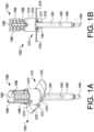
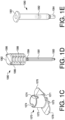
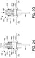
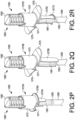
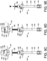
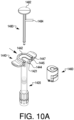
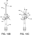
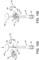
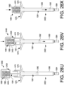
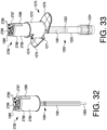
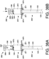
- Device 1050 includes a body 1060, and a blocking component in the form of a flange piece 1070 with a proximal collar 1072 surrounding an opening 1073 (shown in, e.g., FIGS. 3B-3E ), through which a plunger rod 1080 may pass into body 1060.
- Plunger rod 1080 includes an actuation portion 1082 which may be actuated (e.g., pushed or twisted) to rotate plunger rod 1080, or to move plunger rod 1080 longitudinally into body 1060.
- Actuation portion 1082 may be sized and configured to fit (e.g., nest or otherwise fit) inside proximal collar 1072.
- Device 1050 may be, for example, an injection device, such as a syringe, for dispensing a predetermined volume of a formulated drug substance.
- device 1050 may be a pre-filled syringe.
- a user may receive an assembled and packaged device 1050 ready for use, with a volume of formulated drug substance already disposed between a stopper 1062 in body 1060 and an expulsion end 1064 of body 1060.
- an air bubble (not shown) may also be disposed between stopper 1062 and expulsion end 1064.
- device 1050 may be a fillable syringe.
- Body 1060 may be any suitable body configured for holding and expelling a predetermined volume of a formulated drug substance.
- body 1060 may have, e.g., a hollow cylindrical portion.
- Body 1060 may be configured to hold any suitable volume of a formulated drug substance for delivering to, e.g., a patient, and (together with other components of device 1050) to expel a predetermined amount of the held volume through, e.g., expulsion end 1064 in a priming step and/or delivery step.
- body 1060 may be configured to hold and (together with other components of device 1050) expel a relatively small volume of formulated drug substance (e.g., less than about 100 ⁇ l, such as less than about 80 ⁇ l, less than about 60 ⁇ l, less than about 40 ⁇ l, less than about 20 ⁇ l, less than about 10 ⁇ l, about 95 ⁇ l, about 90 ⁇ l, about 85 ⁇ l, about 80 ⁇ l, about 75 ⁇ l, about 70 ⁇ l, about 65 ⁇ l, about 60 ⁇ l, about 55 ⁇ l, about 50 ⁇ l, about 45 ⁇ l, about 40 ⁇ l, about 35 ⁇ l, about 30 ⁇ l, about 25 ⁇ l, about 20 ⁇ l, about 15 ⁇ l, about 10 ⁇ l, or about 5 ⁇ l).
- formulated drug substance e.g., less than about 100 ⁇ l, such as less than about 80 ⁇ l, less than about 60 ⁇ l, less than about 40 ⁇ l, less than about 20 ⁇
- Device 1050 may be further configured to minimize a residual volume of the formulated drug substance remaining in body 1060 after delivering the predetermined small volume to the patient.
- body 1060 may be pre-filled (e.g., prior to completed assembly, packaging, sterilization and/or shipment of device 1050 to users).
- stopper 1062 may be configured to hold a predetermined volume of a formulated drug substance inside a cavity of body 1060.
- Flange piece 1070 may be of any suitable size and/or shape to serve as a blocking component in delivery device 1050, to close, partially close, cover, or partially cover an end of body 1060 opposite expulsion end 1064, and/or to support and hold plunger rod 1080 in place inside body 1060.
- flange piece 1070 may include a distal collar 1075 configured to engage with body 1060 and hold flange piece 1070 in place in relation to body 1060.
- distal collar 1075 may include a lip 1071 that may slide under or otherwise in relation to a body flange 1061, to hold flange piece 1070 in place (e.g., to slidably couple flange piece 1070 to body 1060).
- lip 1071 of distal collar 1075 may be made of a flexible or semi-flexible material, so that it may snap in place over body flange 1061.
- distal collar 1075 or another portion of flange piece 1070 may be adhered to, molded to, or otherwise affixed to, body 1060, or may engage with body 1060 via a friction fit.
- Flange piece 1070 may be or include a blocking component; i.e., part or all of flange piece 1070 may be sized and configured to control movement of plunger rod 1080 by blocking movement of plunger rod 1080 when plunger rod 1080 is in certain configurations relative to flange piece 1070.
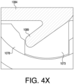
- flange piece 1070 may be configured to control rotational and longitudinal movement of plunger rod 1080, e.g., via opening 1073 (see, e.g., FIGS. 3B-3E ) that complements the size and shape of parts of plunger rod 1080 (e.g., neck 1084 and actuation portion 1082, and/or other portions of plunger rod 1080 as shown in FIGS. 3I and 3M).
- flange piece 1070 may be formed of various materials having a minimum strength and/or rigidity which may provide further control of a rotational or longitudinal movement of plunger rod 1080.
- flange piece 1070 may be configured to resist proximal movement (or "pull back") of plunger rod 1080 (e.g., to inhibit disassembly of device 1050 by retracting plunger rod 1080) up to a predetermined force based at least in part on a material composition of flange piece 1070.
- flange piece 1070 may be configured such that applying a force exceeding the predetermined force may cause one or more of flange piece 1070 and plunger rod 1080 to break, thereby rendering device 1050 inoperable.
- flange piece 1070 may be configured to resist rotational movement of plunger rod 1080 (e.g., to inhibit inadvertent rotation) up to a predetermined force based at least in part on a material composition of flange piece 1070. Additionally and/or alternatively, flange piece 1070 may be configured to resist distal movement of plunger rod 1080 to control a rate of dosage delivery (e.g., to inhibit inadvertent delivery) based at least in part on a material composition of flange piece 1070.
- a rate of dosage delivery e.g., to inhibit inadvertent delivery
- Various other components of device 1050 other than flange piece 1070 may include a material composition providing a frictional interference to inhibit disassembly of device 1050, inadvertent rotation of plunger rod 1080, and/or inadvertent dosage delivery.
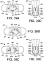
- Proximal collar 1072 of flange piece 1070 may be sized and configured to accept part of actuation portion 1082 of plunger rod 1080, while blocking protrusions 1086 of plunger rod 1080 from moving distally past a predetermined point until plunger rod 1080 is rotated to a particular position.
- collar 1072 may be cylindrical; in alternate embodiments, collar 1072 may have any suitable size or shape compatible with actuation portion 1082.
- Collar 1072 may also include cavities, e.g., slots 1074 into which protrusions 1086 of plunger rod 1080 may be received. Slots 1074 may have proximally-facing openings and may have a depth dimension parallel to a longitudinal axis of device 1050.
- slots 1074 may correspond to a number and configuration of protrusions 1086 on plunger rod 1080.
- slots 1074 may be disposed about a perimeter of collar 1072 in a radially symmetrical configuration.
- collar 1072 may include only one slot 1074.
- the depth of slots 1074 may correspond to a distance plunger rod 1080 must move in order to push stopper 1062 towards expulsion end 1064, and dispense a predetermined volume of formulated drug substance from body 1060 through expulsion end 1064.
- the predetermined volume of formulated drug substance that is to be dispensed from body 1060 may be controlled during manufacturing, by, e.g., selecting a particular depth of slots 1074.
- device 1050 may be configured such that normal variations in manufacturing of other parts of device 1050 (e.g., body 1060 or plunger rod 1080) may not cause variations in the volume of formulated drug substance that is to be dispensed from body 1060.
- the predetermined volume may be controlled by simply varying manufacture of flange piece 1070.
- flange piece 1070 may include one or more flanges 1076, which may be sized and configured to aid a user in holding device 1050 and/or expelling a formulated drug substance from device 1050.
- flange piece 1070 may include two flanges 1076 opposite to one another and extending perpendicularly from a longitudinal dimension of device 1050.
- flange piece 1070 may include other arrangements of a flange or flanges, such as four flanges, or one circumferential flange extending radially outward from a central longitudinal axis of device 1050.
- flange piece 1070 may extend radially outward from a central longitudinal axis of device 1050 farther than a circumference of body 1060. In such embodiments, flange piece 1070 may support device 1050 if device 1050 is placed on a surface, may prevent device 1050 from rolling on a flat surface, and/or may allow device 1050 to be picked up more easily. In still further embodiments, blocking component aspects of flange piece 1070 (e.g., collar 1072) may be separate from flange piece 1070, such that delivery device 1050 includes a separate flange piece and blocking component.
- Plunger rod 1080 in general may be rotatable about a central longitudinal axis (e.g., in one direction or in both directions). In some embodiments, rotation of plunger rod 1080 may be accomplished by grasping and/or twisting actuation portion 1082 relative to flange piece 1070 and/or body 1060. In some embodiments, protrusions 1086 may assist a user in grasping and/or twisting actuation portion 1082 relative to flange piece 1070 and/or body 1060, by providing additional surface area that a user may grasp and/or push against to twist actuation portion 1082.
- plunger rod 1080 may be rotatable relative to flange piece 1070 and/or body 1060.
- plunger rod 1080 may be configured to rotate relative to flange piece 1070 in response to applying a predetermined twisting force onto actuation portion 1082.
- a material composition of flange piece 1070 may be determinative of the predetermined twisting force required to rotate plunger rod 1080 relative to flange piece 1070.
- flange piece 1070 may be formed of various materials having a predetermined rigidity that may generate frictional resistance against plunger rod 1080 to control rotational movement of plunger rod 1080 up to the predetermined force (e.g., to inhibit inadvertent rotation/accidental twisting of plunger rod 1080). Further, a material composition of flange piece 1070 may provide a frictional tolerance to control a distal translation of plunger rod 1080 up to a predetermined force (e.g., to inhibit inadvertent dosage delivery by device 1050).
- a stem 1081 of plunger rod 1080 may have any thickness and cross-sectional shape suitable for fitting into body 1060, while maintaining sturdiness.
- stem 1081 may have as great a thickness, along at least one dimension, as can fit and slide into body 1060.
- a thickness may help in preventing unwanted wobbling of plunger rod 1080 relative to the other components of device 1050.
- stem 1081 may have a smaller thickness while still maintaining sturdiness (e.g., not bending, breaking, or warping during assembly and/or use of device 1050).
- portions of stem 1081 may be configured to allow for plunger rod 1080 to rotate relative to flange piece 1070, whereas other portions of stem 1081 may not (see, e.g., FIGS. 3I-3Q).
- Plunger rod 1080 may also include a distal tip 1083 (see, e.g., FIG. 1D ) sized and configured to push, attach to, or otherwise interface with stopper 1062.
- Tip 1083 may have any size or shape suitable to achieve this purpose.
- tip 1083 may be sized and configured to clip to stopper 1062 via an opening in stopper 1062.
- tip 1083 may have a ball-shape configured to fit into an opening in stopper 1062.
- tip 1083 may present a flat surface parallel to a proximal surface of stopper 1062, and may be configured to push stopper 1062 distally without attaching to stopper 1062.
- tip 1083 may have any shaped surface suitable for pushing stopper 1062 distally.
- neck 1084 of plunger rod 1080 and opening 1073 of flange piece 1070 may have complementary geometries that restrict the extent and direction that plunger rod 1080 (or a part thereof) may rotate, depending on the specific longitudinal and/or rotational position of plunger rod 1080 relative to flange piece 1070.
- actuation portion 1082 of plunger rod 1080 and collar 1072 may also include complementary geometries that control the extent and direction that plunger rod 1080 may move relative to flange piece 1070.
- rotation and/or longitudinal movement of plunger rod 1080 may be restricted based on priming, preparing, and/or drug delivery steps of a method of using device 1050 (see, e.g., the method described with respect to FIGS.
- plunger rod 1080 may be restricted from being moved out of flange piece 1070 in a proximal direction (e.g., falling out or being pulled out) once device 1050 is assembled.
- plunger rod 1080 may be restricted from rotation about a longitudinal axis before device 1050 is in a "primed” state, and/or after device 1050 is in a "delivery" state.
- plunger rod 1080 in the proximal direction may be restricted after device 1050 is in a "primed" and/or “delivery” state by complementary geometries of neck 1084 of plunger rod 1080 and opening 1073 of flange piece 1070 and/or of actuation portion 1082 of plunger rod 1080 and collar 1072 of flange piece 1070.
- this may prevent unwanted plunger rod back out in cases where plunger rod 1080 is not held inside body 1060 by, e.g., being affixed to stopper 1062.
- plunger rod 1080 may be configured to simply contact or rest against stopper 1062, such that proximal movement of plunger rod 1080 does not move stopper 1062 proximally. In such cases, proximal movement of plunger rod 1080 may be prevented by interaction between complementary geometries of plunger rod 1080 and flange piece 1070. Moreover, interaction between actuation portion 1082 of plunger rod 1080 and collar 1072 of flange piece 1070 may restrict longitudinal movement of plunger rod 1080 in a distal direction. As an example, plunger rod 1080 may be restricted from moving distally after the "primed" state but before the "delivery" state.
- protrusions 1086 on actuation portion 1082 may be longitudinally aligned with slots 1074 of collar 1072, allowing for distal movement of plunger rod 1080 to dispense a desired volume of a drug substance from body 1060.
- plunger rod 1080 may include a number and configuration of protrusions 1086 such that each protrusion 1086 may move distally into a slot 1074 when plunger rod 1080 is in a particular position (e.g., a "delivery" state).
- one, two, three, or more protrusions 1086 may extend from actuation portion 1082, corresponding to one, two, three, or more slots 1074, respectively.
- two protrusions 1086 may extend from the sides of actuation portion 1082 in a radially symmetrical configuration (corresponding to two slots 1074 in collar 1072).
- radial symmetry of multiple protrusions 1086 (and slots 1074) may advantageously allow for protrusions 1086 to fit into slots 1074 in multiple configurations (e.g., depending on whether actuation portion 1082 is twisted in one direction or another).
- actuation portion 1082 may be twisted in either direction based on, e.g., user preference, right-handedness or left-handedness, or other factors.
- plunger rod 1080 may not be pulled proximally or backed out of body 1060 (e.g., towards actuation portion 1082) after plunger rod 1080 is in a "primed" state and/or after a desired volume of formulated drug substance has been delivered from device 1050 by depression of plunger rod 1080 into body 1060 (e.g., due to a geometry of neck 1084 and/or opening 1073).
- device 1050 may be configured for ease of use, and may include one or more features that aid a user by providing tactile or visual feedback.
- one, two, or more components of device 1050 may have contrasting colors or textures.
- flange piece 1070 may have a different coloring than plunger rod 1080.
- a single component of device 1050 may have two or more colors or textures.
- actuation portion 1082 may include a first color on a distal part of actuation portion 1082, that becomes covered by collar 1072 when device 1050 is primed, and a second color on a second portion of actuation portion 1082, that moves adjacent to collar 1072 when device 1050 is primed, to help indicate to a user that device 1050 has been properly primed.
- flange piece 1070 may have a different tactile feel than plunger rod 1080 and/or body 1060.
- flange piece 1070 may be relatively rougher or smoother than plunger rod 1080 and/or body 1060.
- one or more components of device 1050 may have textures that aid in holding, gripping, identifying, or using device 1050.
- flange piece 1070 may have a slightly rough or raised texture to aid a user in gripping flanges 1076, and/or to prevent a user's fingers from slipping off of the flanges 1076 during use.
- some or all of flange piece 1070 may have a smooth-feeling surface.
- actuation portion 1082 of plunger rod 1080 may include a rough or raised texture to aid in gripping and rotating plunger rod 1080. For example, as depicted in FIGS.
- actuation portion 1082 may include circumferential ribbing on its side(s). Actuation portion 1082 may have any suitable number of ribs on its side(s) to provide texture. In further embodiments, actuation portion 1082 may have no ribbing on its side(s).
- device 1050 or one or more of its components may include colors, labels or markers, which may indicate contents or a status of device 1050, and/or which may direct or provide instructions to a user of device 1050.
- Examples include one or more labels to indicate a priming position versus a dosage delivery position of the plunger rod, one or more labels to indicate directions in which to rotate or otherwise move plunger rod 1080, and/or one or more labels to indicate an amount of formulated drug substance included in device 1050 (e.g., linear markings on body 1060).
- Labels may be, e.g., adhered or printed on components of device 1050, or may be embossed on, or molded as a part of, components of device 1050.
- one or more textured labels may also serve as a textured, rough, or raised surface to aid a user in gripping or using device 1050.
- One or more exemplary labels may include words, numerals, indicators, and/or symbols (e.g., lines, padlocks, arrows, diagrams, etc.).
- device 1050 may be configured to make one or more sounds during its use.
- device 1050 may make a "clicking" noise upon completion of a priming step, or upon rotation of the plunger rod to a position suitable for dispensing a predetermined volume of a formulated drug substance.
- a "clicking" noise may be produced by, e.g., friction between two or more components (e.g., plunger rod 1080 and flange piece 1070), or a portion of one component contacting another portion (e.g., neck 1084 of plunger rod 1080 contacting opening 1073 of flange piece 1070).
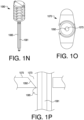
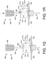
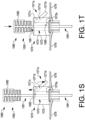
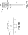
- device 1050 may include one or more detents or protrusions on adjacent surfaces of, e.g., plunger rod 1080 and flange piece 1070, which may produce a clicking sound when contacting one another (e.g., wings 1089 on neck 1084 contacting detents 1078 surrounding opening 1073, as shown in FIGS. 3R-3V). Such sounds may serve as auditory feedback to indicate that a user has reached a particular step in the use of device 1050.
- detents or protrusions on adjacent surfaces of, e.g., plunger rod 1080 and flange piece 1070, which may produce a clicking sound when contacting one another (e.g., wings 1089 on neck 1084 contacting detents 1078 surrounding opening 1073, as shown in FIGS. 3R-3V).
- Such sounds may serve as auditory feedback to indicate that a user has reached a particular step in the use of device 1050.
- device 1050 may include additional features or components to control movement of plunger rod 1080 relative to body 1060.
- flange piece 1070 may include an opening 1079 through which a pin 1077 may be disposed.
- Pin 1077 may be sized and configured to interface with actuation portion 1082 of plunger rod 1080 (e.g., to slide into an opening (not shown) in actuation portion 1082), such that when pin 1077 is inserted so as to engage actuation portion 1082, plunger rod 1080 may not be moved proximally or distally relative to body 1060 and flange piece 1070.
- pin 1077 may also prevent rotational movement of plunger rod 1080 relative to flange piece 1070.
- Pin 1077 may be inserted upon filling and assembly of a device (e.g., device 1050 shown in FIGS. 1A and 1B ), to prevent unwanted movement of plunger rod 1080 prior to its use. In some embodiments, pin 1077 may remain inserted during packaging, transportation, and delivery of device 1050. Before use of device 1050, pin 1077 may be removed or otherwise positioned so that it does not engage actuation portion 1082.
- a device e.g., device 1050 shown in FIGS. 1A and 1B
- pin 1077 may remain inserted during packaging, transportation, and delivery of device 1050. Before use of device 1050, pin 1077 may be removed or otherwise positioned so that it does not engage actuation portion 1082.
- a protrusion 1093 may be disposed at a distal portion of actuation portion 1082, which may be located inside flange piece 1070 upon assembly of device 1050.
- An inward lip 1091 of flange piece 1070 may overhang protrusion 1093, such that actuation portion 1082 may not be pulled proximally out of flange piece 1070.
- either protrusion 1093, lip 1091, or both may be disposed circumferentially about actuation portion 1082, such that lip 1091 blocks protrusion 1093 regardless of a rotational position of actuation portion 1082 relative to flange piece 1070.
- Protrusion 1093 and lip 1091 may have squared-off cross-sectional profiles, as shown in FIG. 1G , angled cross-sectional profiles, as shown in FIG. 1H , or any other suitable cross-sectional profiles.
- a cross-sectional profile of protrusion 1093, lip 1091, or both may be selected to improve ease of manufacturing (e.g., machining or molding the shape of protrusion 1093 or lip 1091), or may be selected to improve assembly (e.g., insertion of plunger rod 1080 into and partially through flange piece 1070).
- actuation portion 1082 may include one or more projections 1096 extending radially outward from an exterior perimeter of protrusion 1093.
- protrusion 1093 may include a pair of projections 1096 disposed about protrusion 1093 at opposite locations relative to one another.
- Projections 1096 may include various suitable sizes, shapes, and/or cross-sectional profiles.
- projections 1096 may have a circular shape with a rounded exterior profile to facilitate movement of protrusion 1093 within flange piece 1070.
- projections 1096 may be positioned along a side of protrusion 1093 that longitudinally aligned with a corresponding side of actuation portion 1082 including protrusions 1086. In other examples, projections 1096 may be positioned along a side of protrusion 1093 that is offset (e.g., not in longitudinal alignment) with the side of actuation portion 1093 including protrusions 1086. Projections 1096 may be formed of various flexible materials, including, for example, a polymer such as plastic, rubber, etc. It should be appreciated that plunger rod 1080 may include additional and/or fewer projections 1096 on protrusion 1093, or other portions of actuation portion 1082, than those shown and described herein without departing from a scope of this disclosure.
- FIG. 1J depicts a distal end portion of flange piece 1070 including one or more recesses 1097 along an interior surface.
- Recesses 1097 may be sized and shaped to receive projections 1096 when protrusion 1093 is received within flange piece 1070 and positioned adjacent and/or in contact with lip 1091.
- lip 1091 may be configured to require application of a hydrodynamic force onto plunger rod 1080 to receive projections 1096 and protrusion 1093 distally of lip 1091 and into flange piece 1070, thereby priming device 1050 and inhibiting retraction (e.g., proximal movement) of plunger rod 1080 relative to flange piece 1070.
- flange piece 1070 may include a plurality of recesses 1097 disposed about the distal end portion in an annular array relative to one another. The plurality of recesses 1097 may be spaced apart from one another about a circumference of flange piece 1070. In some embodiments, flange piece 1070 may include recesses 1097 having varying sizes and/or shapes relative to one another.
- a subset of the plurality of recesses 1097 may be sized and shaped to receive and allow passage of projections 1096 therethrough upon movement of protrusion 1093 relative to flange piece 1070.
- a second subset of the plurality of recesses 1097 may be sized and shaped to receive and inhibit passage of projections 1096 therethrough such that protrusion 1093 is restricted from further movement relative to flange piece 1070, as explained in further detail below.
- flange piece 1070 includes a pair of widened recesses 1097a positioned about opening 1073 (with plunger rod 1080 received therethrough) at opposite locations relative to one another (e.g., spaced about 180 degrees apart from one another).
- Flange piece 1070 further includes a pair of narrowed recesses 1097b positioned about opening 1073 at opposite locations relative to one another (e.g., about 180 degrees from one another).
- a recess 1097a may be positioned about 90 degrees apart from an adjacent recess 1097b, along the circumference of flange piece 1070.
- Widened recesses 1097a may include a center wall transverse (e.g., perpendicular) to a longitudinal length of flanges 1076 and sidewalls that are angled relative to the center wall.
- Narrowed recesses 1097b may include a center wall parallel to the longitudinal length of flanges 1076 and sidewalls that are perpendicular to the center wall. It should be appreciated that widened recesses 1097a may form a larger opening for receiving projections 1096 relative to narrowed recesses 1097b. It should further be understood that sidewalls of recesses 1097a, 1097b may have a height that is parallel to a longitudinal length of device 1050.
- plunger rod 1080 is received through flange piece 1070 and protrusion 1093 is oriented relative to opening 1073 such that projections 1096 are received within widened recesses 1097a.
- the angled sidewalls of widened recesses 1097a may provide clearance to facilitate movement of projections 1096 out of widened recesses 1097a in response to a rotation of plunger rod 1080 relative to flange piece 1070.
- projections 1096 may move along the angled sidewalls of widened recesses 1097a as protrusion 1093 rotates relative to opening 1073.
- projections 1096 may abut against the interior surface of flange piece 1070 defining opening 1073 as protrusion 1093 rotates. Projections 1096 may generate a frictional interference against flange piece 1070 while moving between adjacent recesses 1097.
- FIG. 1M shows protrusion 1093 positioned relative to opening 1073 with projections 1096 aligned with and received in narrowed recesses 1097b.
- plunger rod 1080 may be configured to generate an audible and/or tactile feedback in response to narrowed recesses 1097b receiving projections 1096.
- a "click” or “snap” noise may be generated in response to a release of pressure applied to projections 1096 by the interior surface of flange piece 1070 when projections 1096 are received in narrowed recesses 1097b.
- an audible feedback may be produced in response to projections 1096 expanding and striking one or more walls defining narrowed recesses 1097b when received therein.
- a frictional interference between projections 1096 and flange piece 1070 may be removed upon receipt of projections 1096 within narrowed recesses 1097b.
- the sidewalls of narrowed recesses 1097b may provide a physical restriction that inhibits further movement of projections 1096.
- plunger rod 1080 may be fixed relative to flange piece 1070 such that protrusion 1093 is inhibited from further rotation relative to opening 1073 when projections 1096 are received within narrowed recesses 1097b.
- plunger rod 1080 may additionally or alternatively include a protrusion 1085 on stem 1081, which may be configured to interact with opening 1073 of flange piece 1070, such that protrusion 1085 may only move distally through opening 1073.
- a side 1092 of opening 1073 may be angled to allow for distal passage of protrusion 1085, and to block proximal passage of protrusion 1085, as stem 1081 moves through opening 1073.
- Protrusion 1085 and/or side 1092 may have any suitable shape or configuration to achieve this purpose.
- a shape or configuration of protrusion 1085 and/or side 1092 may be selected to improve ease of manufacturing (e.g., machining or molding the shape of protrusion 1085 and/or flange piece 1070).
- flange piece 1070 may include a movable lever 1071a as seen in FIGS. 1Q-1T .
- Movable lever 1071a may include a first end 1071b extending outwardly from collar 1072 and a second end 1071c disposed within collar 1072.
- Movable lever 1071a may be movable (e.g., pivotable) about a rotation pin 1071d.
- Second end 1071c may be positioned within opening 1073 such that movable lever 1071a is configured to interact with protrusion 1085 upon receipt of plunger rod 1080 in flange piece 1070.
- plunger rod 1080 may be configured to prime device 1050 by translating stem 1081 distally through flange piece 1070 until encountering movable lever 1071a.
- second end 1071c may abut against protrusion 1085 when movable lever 1071a is in an obstructing position.
- Second end 1071c may be configured to inhibit translation of plunger rod 1080 relative to flange piece 1070 when plunger rod 1080 is in a primed position.
- a distance between second end 1071c and protrusion 1085 may define a priming distance for moving plunger rod 1080 to prime device 1050.
- Movable lever 1071a may be configured to move (e.g., pivot) relative to collar 1072 and about rotation pin 1071d to displace second end 1071c from the obstruction position.
- the pivoting axis, along which rotation pin 1071d extends may be substantially perpendicular to the longitudinal axis along which plunger rod 1080 extends.
- movable lever 1071a may be actuated in response to moving first end 1071b distally toward flange 1076 and about rotation pin 1071d.
- first end 1071b may be actuated in response to receiving a distally-directed force applied thereto by, for example, a user of device 1050.
- Second end 1071c may be moved in a proximal direction away from flange 1076 and relative to rotation pin 1071d in response to first end 1071b moving distally, thereby causing second end 1071c to disengage protrusion 1085.
- movable lever 1071a may allow plunger rod 1080 to translate relative to flange piece 1070 until protrusion 1085 encounters an abutment 1072a positioned at a distal end of opening 1073. Abutment 1072a may cause plunger rod 1080 to settle into a dose completion position of plunger rod 1080 when protrusion 1085 is engaged thereto. It should be appreciated that a distance between second end 1071c and abutment 1072a may define a dosage delivery distance for moving plunger rod 1080 to dispense a controlled volume of substance from device 1050.
- actuation portion 1082 of plunger rod 1080 may additionally or alternatively include one or more extensions 1087 configured to interface with side openings 1094, 1095 in collar 1072 of flange piece 1070.
- Extensions 1087 may extend distally from actuation portion 1082, and may have an angled or rounded distal portion sized and configured to be pushed inward toward a central axis of plunger rod 1080 when actuation portion 1082 is pushed distally into collar 1072.
- the angled or rounded distal portion of each extension 1087 may include a hook or clip shaped part 1087a.
- Extensions 1087 may additionally be made of a flexible material, allowing them to be pushed inward into collar 1072 and spring back outwards when no longer being restricted by a side of collar 1072.
- Side openings 1094, 1095 in collar 1072 may be sized and configured to receive hook or clip shaped part 1087a of an extension 1087, such that once an extension 1087 reaches a side opening 1094 or 1095, a hook or clip shaped part 1087a may spring outward into the side opening 1094 or 1095 and thereafter prevent proximal movement of plunger rod 1080.
- a number of extensions 1087 may coincide with a number of each of side openings 1094 and side openings 1095, such that each extension 1087 may be received in a corresponding side opening 1094 or 1095 simultaneously as plunger rod 1080 moves distally relative to flange piece 1070.
- first side openings 1094 may be configured to receive hook or clip shaped parts 1087a of extensions 1087 upon assembly of device 1050, to prevent proximal movement of plunger rod 1080 once plunger rod 1080 is inserted to a ready-to-use position.
- hook or clip shaped part 1087a of each extension 1087 is received in first side openings 1094, it may make a "clicking" sound as it interfaces with collar 1072, thereby providing auditory and/or tactile feedback, indicating that the device is in a ready-to-use position.
- first side openings 1094 may each extend around a partial circumference of collar 1072, such that the hook or clip shaped parts 1087a of extensions 1087 may be received in side openings 1094 in a range of rotational positions of plunger rod 1080 relative to flange piece 1070.
- Second side openings 1095 may be configured to receive hook or clip shaped parts 1087a of extensions 1087 once device 1050 is in a "delivery" configuration (e.g., after priming and additional rotation of actuation portion 1082 to align protrusions 1086 with slots 1074).
- extensions 1087 are longitudinally aligned with protrusions 1086, and, as depicted in FIGS.
- side openings 1095 are likewise longitudinally aligned with slots 1074, to allow for distal movement of actuation portion 1082 further into collar 1072 when device is in the "delivery” configuration. It should be appreciated that device may be transitioned to the "delivery" configuration in response to applying a distally-directed force onto actuation portion 1082, to overcome an engagement of side openings 1094 with extensions 1087, and a rotative force to overcome a frictional force between an interior of collar 1072 and extensions 1087.
- extensions 1087 and side openings 1094, 1095 may be in any suitable complementary configuration to assist in controlling proximal movement of plunger rod 1080.
- side openings 1094 may be positioned along collar 1072 in longitudinal alignment with side openings 1095.
- Device 1050 may be primed upon receiving hook or clip shaped parts 1087a of extensions 1087, initially positioned proximally of side openings 1094, within side openings 1094.
- a feedback e.g., tactile, auditory, etc.
- a proximal end of collar 1072 may resist distal advancement of plunger rod 1080 relative to flange piece 1070 in response to hook or clip shaped parts 1087a being engaged to collar 1072 at side openings 1094. Applying a distally-directed force onto plunger rod 1080 may cause extensions 1087 to be released from side openings 1094 and translated distally through collar 1072 until received within side openings 1095.
- plunger rod 1080 may be maintained in a constant radial orientation during a priming step and delivery step of device 1050.
- additional and/or fewer side openings may be included along a circumferential wall of collar 1072 in longitudinal alignment and/or offset (e.g., not longitudinally aligned) with side openings 1094, 1095.
- flange piece 1070 may alternatively include one or more inner projections 1095' in lieu of side openings 1095 shown and described above.
- plunger rod 1080 may be preassembled into flange piece 1070 with extensions 1087 ( FIG. 1V ) squeezed into collar 1072 and positioned relatively proximal to side openings 1094.
- Device 1050 may be primed by pushing plunger rod 1080 distally through flange piece 1070 until extensions 1087 are received within side openings 1094.
- a feedback e.g., tactile, auditory, etc.
- side openings 1094 may be flared and/or extensions 1087 may have a distally-tapering profile to facilitate further distal advancement of plunger rod 1080 from a primed position to a dose completion position.
- plunger rod 1080 may cause extensions 1087 to bend radially-inward toward one another, thereby allowing plunger rod 1080 to translate distally to deliver a dose from device 1050.
- Plunger rod 1080 may continue to translate distally relative to collar 1072 until hook or clip shaped parts 1087a ( FIG. 1V ) encounter inner projections 1095'.
- Inner projections 1095' may be configured to contact extensions 1087 and fix plunger rod 1080 to the dose completion position, and/or prevent further distal movement of plunger rod 1080 relative to flange piece 1070.
- Inner projections 1095' may include complimentary hooks or clip-shaped parts that are sized and/or shaped to interact with hook or clip shaped parts 1087a or extensions 1087. It should be appreciated that a distance between side openings 1094 and inner projections 1095' may define a dosage delivery distance to dispense a controlled volume of substance from device 1050.
- flange piece 1070 may include a fixed sleeve 1072P extending proximally from collar 1072.
- Fixed sleeve 1072P may have a circular cross-section defining an inner channel with an opening at each terminal end of the fixed sleeve 1072P.
- the inner channel of fixed sleeve 1072P may extend through a longitudinal length of fixed sleeve 1072P and may be longitudinally aligned with opening 1073 ( FIG. 1O ) such that a respective longitudinal axis of the inner channel and opening 1073 are coaxial with one another.
- Fixed sleeve 1072P may be sized, shaped, and configured to receive stem 1081.
- fixed sleeve 1072P may be integral with collar 1072, while in other embodiments fixed sleeve 1072P may be a separate component assembled onto flange piece 1070.
- Fixed sleeve 1072P may include a plurality of openings that are sized and shaped to receive protrusion 1085.
- fixed sleeve 1072P may include a pair of proximal openings 1072Q and a pair of distal openings 1072R longitudinally spaced apart from one another by an offset distance.
- the pair of proximal openings 1072Q are located at the same longitudinal position as one another
- the pair of distal openings 1072R are located at the same longitudinal position as one another.
- the longitudinal offset between proximal openings 1072Q and distal openings 1072R may define a dosage delivery distance for moving plunger rod 1080 to dispense a controlled volume of substance from device 1050.
- the longitudinal offset between openings 1072Q, 1072R may define a priming distance of device 1050 such that protrusion 1085 may be initially received within proximal openings 1072Q during an assembly of device 1050 to inhibit proximal retraction of plunger rod 1080.
- a dosage delivery distance may correspond to a longitudinal offset between a distal end of actuation portion 1082 and a bottom surface of collar 1072 when protrusion 1085 is received within distal opening 1072R.
- an additional set of openings may be included on fixed sleeve 1072P (e.g., proximal of proximal openings 1072Q, distal of proximal openings 1072Q, and/or distal of distal openings 1072R) to further define a priming distance and/or dosage delivery distance.
- a proximal end of fixed sleeve 1072P may include an angled interface 1071P defining a proximal opening of fixed sleeve 1072P.
- Angled interface 1071P may be tapered radially-inward toward the inner channel of fixed sleeve 1072P and configured to guide stem 1081 and protrusion 1085 into the inner channel.
- protrusion 1085 may extend radially outward from stem 1081 in opposing lateral directions and may be compressible and/or formed of a flexible/deformable material, such that protrusion 1085 is configured to retract or deform radially inward into and/or toward stem 1081 in response to a force being applied thereto.
- protrusion 1085 may be configured to at least partially deform fixed sleeve 1072P to facilitate movement of protrusion 1085 toward and/or between openings 1072Q, 1072R.
- fixed sleeve 1072P may be formed of a flexible material operable to flex radially-outward when applying a distally-directed force onto stem 1081, thereby causing protrusion 1085 to apply a radial force onto fixed sleeve 1072P.
- fixed sleeve 1072P may be configured to receive plunger rod 1080 through the inner channel and allow stem 1081 to pass through collar 1072 to prime device 1050.
- Protrusion 1085 may be received within fixed sleeve 1072P in response to encountering angled surface 1071P and compressing radially inward relative to stem 1081 until plunger rod 1080 is moved distally enough so that protrusion 1085 is received by proximal openings 1072Q.
- protrusion 1085 may be configured to expand radially outward (decompress) when longitudinally aligned with proximal openings 1072Q to lock stem 1081 relative to flange piece 1070.
- device 1050 may be in a primed position such that further translation of stem 1081 distally relative to fixed sleeve 1072P and flange piece 1070 may deliver a dose from device 1050.
- device 1050 may be preassembled with protrusion 1085 received in proximal openings 1072Q such that translation of stem 1081 distally relative to fixed sleeve 1072P may prime device 1050 until protrusion 1085 is received within distal openings 1072R.
- protrusion 1085 may be positioned within proximal openings 1072Q applying a distally-directed force onto stem 1081 may cause fixed sleeve 1072P to compress (or deform) protrusion 1085 radially inward, thereby allowing stem 1081 to translate distally relative to fixed sleeve 1072P.
- protrusion 1085 may be manually compressed (or deformed) by applying a radially inward-directed force through proximal openings 1072Q.
- Protrusion 1085 may move distally through an inner channel of fixed sleeve 1072P and may be received by distal openings 1072R.
- device 1050 may transition from the primed position to a dose completion position when protrusions 1085 are received within distal openings 1072R, thus delivering the dose.
- a volume of the dose delivered by device 1050 may be controlled based on the longitudinal offset distance between proximal openings 1072Q and distal openings 1072R.
- fixed sleeve 1072P may include additional openings for receiving protrusion 1085 after priming and delivering a dose to inhibit proximal retraction of stem 1081 (e.g., pull back of plunger rod 1080) relative to flange piece 1070.
- protrusion 1085 may be received within proximal openings 1072Q during an assembly of device 1050 at a manufacturing stage such that distal openings 1072R may define a priming position and a third set of openings (not shown) distal to distal opening 1072R may define a dosage delivery position.
- a bottom, interior surface of flange piece 1070 distal to distal opening 1072R may define the dosage delivery position of plunger rod 1080.
- flange piece 1070 may include a movable sleeve 1072S extending distally and proximally from collar 1072.
- Movable sleeve 1072S may have a circular cross-section defining an inner channel with an opening at each terminal end of movable sleeve 1072S.
- the inner channel of movable sleeve 1072S may extend through a longitudinal length of movable sleeve 1072S.
- Movable sleeve 1072S may be sized, shaped, and configured to be received through opening 1073, and the inner channel of movable sleeve 1072S may be sized to receive stem 1081.
- Movable sleeve 1072S may be fixed relative to collar 1072 when in an preassembled configuration and may be movable relative to collar 1072 upon engagement with plunger rod 1080.
- Movable sleeve 1072S may include a plurality of openings that are sized and shaped to receive protrusion 1085.
- movable sleeve 1072S may include a proximal opening 1072U at a proximal end of movable sleeve 1072S and a distal opening 1072T at a distal end of movable sleeve 1072S.
- a proximal end of movable sleeve 1072S may further include an angled interface 1071S defining a proximal opening of movable sleeve 1072S.
- Angled interface 1071S may be tapered radially-inward toward the inner channel of movable sleeve 1072S and configured to guide stem 1081 and protrusion 1085 into the inner channel of movable sleeve 1072S.
- protrusion 1085 may extend radially outward from stem 1081 in opposite directions and may be compressible such that protrusion 1085 is configured to compress into and/or toward stem 1081 in response to a force being applied thereto.
- the proximal end of movable sleeve 1072S may be positioned adjacent to a proximal end of collar 1072 and a distal end of movable sleeve 1072S may be positioned adjacent to a distal end of collar 1072 when in the preassembled position.
- Plunger rod 1080 may be received through the inner channel of movable sleeve 1072S with stem 1081 extending through collar 1072.
- Protrusion 1085 may be received within distal opening 1072T such that plunger rod 1080 may be fixed to movable sleeve 1072S.
- Protrusion 1085 may be configured to exit distal opening 1072T and expand laterally outward in response to plunger rod 1080 translating relative to movable sleeve 1072S.
- applying a distally-directed force onto actuation portion 1082 may cause protrusion 1085 to compress radially inward, thereby allowing stem 1081 to translate distally relative to movable sleeve 1072S.
- protrusion 1085 may exit distal opening 1072T and expand upon translating distally from a distal end of movable sleeve 1072S.
- Device 1050 may transition from a preassembled state to a primed state, in response to stem 1081 translating distally relative to collar 1072, until actuation portion 1082 abuts against a proximal end of movable sleeve 1072S. In this instance, device 1050 may be in a primed state and further translation of stem 1081 relative to collar 1072 may be inhibited by the presence of movable sleeve 1072S.
- plunger rod 1080 may couple to movable sleeve 1072S in response to proximal translation of stem 1081 relative to collar 1072 until protrusion 1085 engages proximal opening 1072U.
- protrusion 1085 may be in a compressed state when translating through an inner channel of movable sleeve 1072S and may expand into proximal opening 1072U upon longitudinal alignment therewith.
- a distal translation of plunger rod 1080 relative to flange piece 1070 may provide a simultaneous movement of movable sleeve 1072S relative to collar 1072.
- a collective length of movable sleeve 1072S and plunger rod 1080 may be greater than a longitudinal length of plunger rod 1080 alone.
- plunger rod 1080 may be configured to move movable sleeve 1072S through a channel of flange piece 1070 by a predetermined distance until actuation portion 1082 encounters a proximal end of collar 1072.
- Plunger rod 1080 may be configured to deliver a dose from device 1050 in response to translating movable sleeve 1072S distally relative to collar 1072. It should be appreciated that the dosage delivered by device 1050 may be controlled based on the predetermined distance between actuation portion 1082 and collar 1072 when protrusion 1085 is received within proximal opening 1072U.
- flange piece 1070 may be configured to inhibit proximal movement of movable sleeve 1072S relative to collar 1072 when protrusion 1085 is received within proximal opening 1072U.
- flange piece 1070 may include one or more blocking components operable to restrict proximal retraction of movable sleeve 1072S from opening 1073.
- plunger rod 1080 may include at least one protrusion 1085W positioned on actuation portion 1082.
- protrusion 1085W may be positioned at or adjacent a distal end of actuation portion 1082 such that protrusion 1085W may be received within flange piece 1070 in response to translation of plunger rod 1080 into collar 1072.
- flange piece 1070 may include one or more channels formed along an inner surface of collar 1072.
- collar 1072 may include a first (proximal) helical channel 1071W formed along an interior of collar 1072 and having a first curvature, and a second (distal) helical channel 1072W formed along the interior of collar 1072 and having a different and/or opposite curvature than the first helical channel 1071W.
- first helical channel 1071W may be concave
- second helical channel 1072W may be convex when viewed from the same vantage point.
- first helical channel 1071W may be convex when viewed from the proximal end of actuation portion 1082, while second helical channel 1072W is concave from the same vantage point. Further, second helical channel 1072W may be longitudinally spaced apart from first helical channel 1071W. First helical channel 1071W may be connected with second helical channel 1072W by an intermediate, third channel 1073W extending therebetween.
- Third channel 1073W may extend along or substantially parallel to a longitudinal axis of collar 1072. It should be understood that a size, shape, and/or orientations of the one or more channels on collar 1072 are merely exemplary such that other suitable configurations may be included without departing from a scope of this disclosure. As described in detail below, the plurality of channels 1072 are configured to receive protrusion 1085W. In some embodiments, first helical channel 1071W and second helical channel 1072W may be threaded and configured to mesh with a corresponding component of plunger rod 1080 (e.g., protrusion 1085W).
- Opposite rotational movement may be required for protrusion 1085W to traverse through first helical channel 1071W and second helical channel 1072W.
- a first rotational movement of actuation portion e.g., clockwise
- an opposing rotational movement e.g., counterclockwise
- protrusion 1085W may traverse through second helical channel 1072W.
- protrusion 1085W may be received within collar 1072 in response to a distal translation of actuation portion 1082 toward flange piece 1070.
- protrusion 1085W may be received within first helical channel 1071W and moved therethrough in response to a rotation of plunger rod 1080 (e.g., in a first direction) relative to flange piece 1070.
- plunger rod 1080 may be configured to translate axially in a distal direction relative to flange piece 1070 as plunger rod 1080 rotates within collar 1072, due to the curvature of first helical channel 1071W.
- plunger rod 1080 may translate a first distance defined by a configuration of first helical channel 1071W until reaching a terminal end of first helical channel 1071W.
- the first distance may correspond to a priming step of device 1050 such that device 1050 may be at least partially primed upon protrusion 1085W moving through first helical channel 1071W.
- protrusion 1085W may be positioned at a terminal end of first helical channel 1071W and a proximal (e.g., top) end of third channel 1073W.
- plunger rod 1080 may experience a tactile feedback formed by the terminal end of first helical channel 1071W.
- Plunger rod 1080 may be translated distally through third channel 1073W to complete a priming step of device 1050, as shown in FIG. 2K .
- first helical channel 1071W and third channel 1073W may collectively define a priming distance of device 1050 such that plunger rod 1080 is in a primed position when protrusion 1085W translates through third channel 1073W.
- plunger rod 1080 may be rotated in the second direction (opposite of the first direction) to translate plunger rod 1080 distally by a second distance that is defined by a configuration of second helical channel 1072W.
- the second distance may be less than, greater than, and/or substantially equal to the longitudinal dimension of second helical channel 1072W, depending on the particular application and need.
- Plunger rod 1080 may be rotated in the second direction and translated by the second distance until reaching a terminal end of second helical channel 1072W to deliver a dose from device 1050.
- the second distance may correspond to a dosage delivery step of device 1050 such that device 1050 may deliver the dose upon protrusion 1085W moving through second helical channel 1072W and arriving at a dose completion position.
- plunger rod 1080 may include a protrusion, a knob, and/or a thread 1085X positioned on actuation portion 1082.
- thread 1085X may be positioned about a circumference of actuation portion 1082 and along a distal end such that thread 1085X may be received within flange piece 1070 in response to translation of plunger rod 1080 into collar 1072.
- Flange piece 1070 may further include a threaded portion 1072X disposed within opening 1073 and forming a helical path that is configured to receive thread 1085X.
- threaded portion 1072X may be positioned along a proximal portion of opening 1073 such that a distal portion of opening 1073 may include a non-threaded portion 1071X.
- threaded portion 1072X may define a longitudinal distance corresponding to a priming step of device 1050 and non-threaded portion 1071X may define a distance corresponding to a dosage delivery step of device 1050.
- actuation portion 1082 may be translated distally toward flange piece 1070 until thread 1085X encounters a distal end of collar 1072.
- Rotation of plunger rod 1080 in a first direction e.g., clockwise or counter clockwise
- rotation of plunger rod 1080 may provide axial/longitudinal translation of actuation portion 1082 into collar 1072 as thread 1085X moves through the helical path of threaded portion 1072X. It should be appreciated that rotation and translation of thread 1085X through threaded portion 1072X may transition device 1050 from a ready position ( FIG.
- a feedback e.g., tactile, auditory, etc. may be generated in response to thread 1085W exiting threaded portion 1072X and/or entering non-threaded portion 1071X.
- actuation portion 1082 may be translated distally relative to flange piece 1070 to deliver a dose from device 1050 by application of a distally-directed force against actuation portion 1082.
- Thread 1085X may move through the distal portion of opening 1073 when thread 1085X is positioned within non-threaded portion 1071X.
- a longitudinal length of non-threaded portion 1071X defined between a distal end of thread portion 1072X and a distal end of opening 1073 may control a dosage delivery of device 1050.
- Device 1050 may complete delivery of a dose when actuation portion 1082 engages a proximally-facing and distal surface of collar 1072 and plunger rod 1080 arrives at the dose completion position.
- FIGS. 2P-2T illustrate further embodiments of a flange piece that may be configured and operable similar to flange piece 1070 shown and described above except for the differences explicitly noted herein. It should be understood that like reference numerals are used to identify like components and the flange pieces described below may be readily incorporated with one or more components of device 1050 shown and described above.
- a flange piece 1070A may include one or more flanges 1076A that may be sized and configured to aid a user in holding device 1050 and/or expelling a formulated drug substance from device 1050.
- Flanges 1076A may be further sized and/or shaped to allow a user to hold device 1050 with a plurality of hand/grip positions, arrangements, and/or orientations.
- flanges 1076A may be sized and/or shaped such that flange piece 1070A may be held similar to a writing instrument (e.g., pencil, pen, etc.) without requiring use of flanges 1076A, or sized in accordance with the example shown in FIG. 24A such that flanges 1076A may abut against one or more fingers of a user.
- Flange piece 1070A may include a pair of flanges 1076A extending radially outwardly from collar 1072 in opposite radial directions relative to one another.
- Flanges 1076A may extend transversely from collar 1072 (e.g., flanges 1076A may include an angled surface that is sloped radially-inward in a distal direction) and configured to inhibit a user's fingers from slipping off of flange piece 1070A during use of device 1050.
- Flanges 1076A may be coupled to one another to form a semi-circular profile with a minimal radius relative to collar 1072. Accordingly, flanges 1076A may form a slim profile to facilitate visualization of a target treatment site at a distal end of device 1050 (not shown) when using device 1050 from a perspective proximal of finger flange 1070A. It should be understood that flange piece 1070A may include various other quantities and/or arrangements of flanges 1070A than those shown and described herein without departing from a scope of this disclosure. In other embodiments, flanges 1076 may include various other suitable sizes and/or shapes.
- Flange piece 1070A may further include a distal collar 1075A extending distally from collar 1072 and configured to engage body 1060 to hold flange piece 1070A in a fixed position relative to body 1060.
- Distal collar 1075A may be adhered to, molded, or otherwise affixed to body 1060, or may engage body 1060 via a friction fit.
- distal collar 1075A includes a longitudinal length that is generally less than a longitudinal length of collar 1072.
- distal collar 1075A may be sized sufficiently small enough to facilitate adequate exposure of body 1060 for user grasp and/or manipulation during use of device 1050.
- distal collar 1075A may include a material composition that is similar to and/or different from collar 1072.
- distal collar 1075A may be formed of a flexible material such that distal collar 1075A may be configured to flex radially-outward when receiving body 1060 into flange piece 1070A and flex radially-inward once body 1060 is fully received to facilitate a snap-fit connection (without breaking distal collar 1075A). It should be appreciated that, in other embodiments, flange piece 1070A may omit distal collar 1075A entirely.
- a flange piece 1070B may include a distal collar 1075B that is substantially longer than distal collars 1075, 1075A shown and described above.
- distal collar 1075B may be enlarged with a longitudinal length that is greater than a longitudinal length of collar 1072.
- distal collar 1075A may be sized sufficiently large enough to encompass a substantial length of body 1060.
- an exterior surface of distal collar 1075B may provide an interface for a user to grasp and/or manipulate during use of device 1050.
- distal collar 1075B may include an expanded diameter that exceeds a diameter of body 1060 to provide an enhanced surface area for grasping flange piece 1070B.
- distal collar 1075B may have a widened size and/or shape to facilitate ease in gripping and/or manipulating device 1050.
- distal collar 1075B may have a barrel-shape with a convex outer surface when viewed from an exterior of device flange piece 1070B.
- a flange piece 1070C may include a distal collar 1075C that is substantially similar to distal collar 1075B and includes a longitudinal length that is greater than a longitudinal length of collar 1072.
- an exterior surface of distal collar 1075C may be configured to provide an interface for a user to grasp and/or manipulate during use of device 1050.
- Distal collar 1075C may include a slim profile with a diameter that is greater than a diameter of body 1060 such that distal collar 1075C does not substantially increase a profile of body 1060. Stated differently, distal collar 1075C may have a narrowed size relative to distal collar 1075B.
- distal collar 1075C may include a terminal lip 1077C that extends radially outward at a distal end. Terminal lip 1077C may be sized, shaped, and configured to enhance gripping and/or manipulation of distal collar 1075C.
- distal collar 1075C may have a flared-shape with a concave outer surface when viewed from an exterior of device flange piece 1070C.
- a flange piece 1070D may include a collar 1072D having a proximal lip 1074D.
- Proximal lip 1074D may define an irregular surface configured to interface with plunger rod 1080 when actuation portion 1082 is received by collar 1072D.
- proximal lip 1074D may include a pair of recessed surfaces 1075D positioned along opposing sides from one another along proximal lip 1074D. In other words, recessed surfaces 1075D may be separated from one another by surfaces and/or portions of proximal lip 1074D that are not recessed.
- recessed surfaces 1075D may be positioned adjacent to slots 1074 and may define a pathway for moving plunger rod 1080 relative to collar 1072D for priming and delivering a dose from device 1050.
- recessed surfaces 1075D may include a spiral configuration (e.g., have a distally-directed slope) such that recessed surfaces 1075D may be tapered in a distal direction between a first ledge 1073D and a second ledge 1076D.
- flange piece 1070D may include visualization mechanisms, such as, for example, one or more labels or markings disposed on collar 1072D to provide instructions to a user of device 1050.
- the one or more labels e.g., numbering
- the one or more labels may indicate directions in which to rotate or otherwise move plunger rod 1080 relative to flange piece 1070D to prime and deliver a dosage from device 1050.
- the one or more labels may include markings that indicate a start position (e.g., "1"), a priming position (e.g., "2”), and a dosage delivery position (e.g., "3") of protrusions 1086 relative to proximal lip 1074D.
- the one or more labels may be adhered, printed, embossed, and/or molded onto collar 1072D.
- flange piece 1070D may be configured to allow movement of plunger rod 1080 in a single direction when priming and delivering a dosage from device 1050.
- plunger rod 1080 (not shown) may initially be received through flange piece 1070D and actuation portion 1082 may be positioned against collar 1072D with protrusions 1086 positioned along a first end of recessed surfaces 1075D at marking "1" and opposite of slot 1074.
- Protrusions 1086 may only be rotated in a single direction along recessed surface 1075D, toward marking "2,” due to first ledge 1073D inhibiting protrusions 1086 from moving in an opposite direction away from marking "2".
- second ledge 1076D may further prevent protrusions 1086 from moving past slots 1074 and passing by marking "3".
- a configuration of proximal lip 1074D is exemplary such that flange piece 1070D may include various other sizes, shapes, and/or configurations of proximal lip 1074D and/or recessed surfaces 1075D than those shown and described herein to facilitate movement of plunger rod 1080 during use of device 1050.
- the components of device 1050 may include one or more color indicators in lieu of and/or in addition to the markings described above to provide instructions to a user of device 1050.
- device 1050 may include colors, symbols (e.g., arrows), and the like indicating a direction in which to rotate or otherwise move plunger rod 1080 relative to flange piece 1070D to prime and deliver a dosage.
- an exterior surface of plunger rod 1080 may be provided with different colors along various portions of actuation portion 1082 to indicate a respective start position (e.g., green), priming position (e.g., yellow), and dosage delivery position (e.g., red) of plunger rod 1080 relative to collar 1072D.
- the one or more color indicators may be printed or molded onto plunger rod 1080.
- the various portions of plunger rod 1080 may include different textures in lieu of and/or in addition to the color indicators described above to provide instructions to a user of device 1050.
- Components of device 1050 may be made of any suitable material, and each component may be made from the same or different materials as other components. It should be appreciated that, in some embodiments, one or more components of device 1050 (e.g., flange piece 1070, proximal collar 1072, plunger rod 1080, actuation portion 1082, and more) may be formed of a flexible material having sufficient flexibility to prevent breakage during flexing. In some embodiments, the one or more components of device 1050 may be rigid and have enough strength to maintain shape and provide support. In other embodiments, one or more components of device 1050 (or at least a portion of a component) may having a varying rigidity along a longitudinal length or lateral width such that the component may have a variable flexibility.
- one or more components of device 1050 e.g., flange piece 1070, proximal collar 1072, plunger rod 1080, actuation portion 1082, and more
- the one or more components of device 1050 may be rigid and have enough strength to maintain
- the one or more components of device 1050 may have sufficient flexibility to prevent breakage during flexing while also having sufficient rigidity and strength to maintain shape and provide support. In some embodiments, such features may further provide a user feedback (e.g., tactile, audible, visual, etc.) when flexing and/or interacting with other components of device 1050.
- each of body 1060, flange piece 1070, and plunger rod 1080 may be made of a material including a polymer, such as a plastic.
- one or more of body 1060, flange piece 1070, and plunger rod 1080 may include multiple different materials (e.g., glass, rubber, and/or plastic).
- the cylindrical portion of body 1060 may be made of glass, Plexiglas, or any other suitable polymer (e.g., cyclic olefin polymer or cyclic olefin copolymer) or other material
- stopper 1062 may be made of, e.g., plastic, rubber, or other polymer or copolymer.
- flange piece 1070 may include a polypropylene homopolymer, an ABS (Acrylonitrile, Butadiene, and Styrene) polymer, ABS polycarbonate blend, and other suitable materials.
- plunger rod 1080 may include an ABS polycarbonate blend.
- one or more components of device 1050 may be formed of a flexible and/or deformable material composition providing greater tolerances for flexing or deforming said components (e.g., without breaking) when priming or delivering a dose from device 1050.
- a portion of body 1060 configured to contain a formulated drug substance may be made of a transparent or translucent material.
- flange piece 1070 and plunger rod 1080 may be made of the same, similar, or different materials, such as similar or different plastics (e.g., each having a similar or different hardness).
- parts of device 1050 may include elastic materials.
- parts of device 1050 may include rubber or plastic configured to allow a user to better grip device 1050, or to create an airtight or otherwise sealing fit between two components of device 1050 (e.g., between body 1060 and stopper 1062).
- plunger rod 1080 may be made of a material having some flexibility, e.g., to allow for bending of extensions 1087.
- actuation portion 1082 and/or extensions 1087 may be made of a material having some flexibility, e.g., to allow for bending of extensions 1087.
- One or more of the materials listed above e.g., plastic, rubber, polymers, or copolymers
- device 1050 may be suitable for sterilization, e.g., heat or chemical sterilization.
- FIGS. 2A and 2B depict an exemplary method of assembling the delivery device depicted in FIGS. 1A-1E .
- Flange piece 1070 may be assembled to body 1060, as shown in FIG. 2A .
- the assembly of flange piece 1070 to body 1080 may include sliding, snapping, adhering, or otherwise affixing the two components together.
- flange piece 1070 may be slid onto body 1060, e.g., such that lip 1071 of flange piece 1070 engages with body flange 1061.
- Plunger rod 1080 may be inserted through the assembled flange piece 1070 and body 1060, such that a distal end of plunger rod 1080 contacts stopper 1062.
- the assembled device 1050 may then be in a configuration suitable for packaging, sterilization, and/or use.
- FIGS. 3C-3F depict an exemplary method of assembling device 1050 in which actuation portion 1082 includes extensions 1087 and collar 1072 includes side openings 1094.
- plunger rod 1080 may be inserted through flange piece 1070 until the hook or clip portions of extensions 1087 are received within side openings 1094, at which point the assembled device 1050 may be in a configuration suitable for packaging, sterilization, and/or use.
- side openings 1094 may be configured to inhibit a proximal retraction of plunger rod 1080 relative to flange piece 1070 once the hook or clip portions of extensions 1087 are received therein.
- Side openings 1094 may function as a first lock when device 1050 is placed into an initial assembly state to prevent disassembly of device 1050.
- side openings 1095 may be configured to inhibit a proximal retraction of plunger rod 1080 once the hook or clip portions of extensions 1087 are received therein. Side openings 1095 may function as a second lock when device 1050 is placed in a dosage delivery state to prevent extracting patient fluid after completion of drug/medicament delivery. It should be appreciated that side openings 1094, 1095 may generate a feedback indicating a relative position of plunger rod 1080 to flange piece 1070, such as, for example, an audible feedback, a tactile feedback, and the like. In some embodiments, device 1050 may include additional and/or fewer side openings 1094, 1095 than those shown and described herein to increase and/or decrease a quantity of locks on device 1050.
- assembling device 1050 may include pre-filling body 1060 before combining it with flange piece 1070 and stopper 1080; for example, a predetermined amount of drug substance may be disposed in body 1060 between stopper 1062 and needle end 1064.
- a predetermined amount of drug substance may be disposed in body 1060 between stopper 1062 and needle end 1064.
- an alternate order of assembly of the components of device 1050 may be employed, depending on contemplated variations in the structures of components of device 1050.
- plunger rod 1080 may be first inserted through flange piece 1070, and the combined flange piece 1070 and plunger rod 1080 may be assembled to body 1060, e.g., such that flange piece 1070 snaps over a proximal body flange 1061 of body 1060 and plunger rod 1080 is inserted into body 1060.
- FIGS. 4A-4F depict an exemplary method of using device 1050, according to aspects of the present disclosure.
- device 1050 may hold a volume of a drug substance in between stopper 1062 and expulsion end 1064.
- a priming distance p may exist between protrusions 1086 and a proximal end of proximal collar 1072, and protrusions 1086 may be non-aligned with slots 1074.
- plunger rod 1080 may be moved longitudinally further into body 1060. For example, a user may press actuation portion 1082 partially into proximal collar 1072 of flange piece 1070.
- device 1050 may be held in an inverted position during this step, to ensure that air trapped in body 1060 may be expelled via expulsion end 1064, as stopper 1062 is pushed distally by plunger rod 1080.
- plunger rod 1080 may be prevented from rotating about the longitudinal axis of the syringe, due to the geometries of opening 1073 in flange piece 1070, and neck 1084 of plunger rod 1080 (as shown in the top cross-sectional view in FIG. 4B ). As shown in FIG.
- the priming step may be stopped when protrusions 1086 of plunger rod 1080 abut a proximal end of proximal collar 1072.
- neck 1084 of plunger rod 1080 may be positioned longitudinally with respect to opening 1073 of flange piece 1070, such that it may now be rotatable with respect to flange piece 1070.
- a narrower portion of neck 1084 may be disposed inside opening 1073 than when device was in a pre-use configuration.
- device 1050 may be in a primed configuration.
- plunger rod 1080 may be rotated about a longitudinal axis to align protrusions 1086 with slots 1074.
- a user may grasp and twist actuation portion 1082.
- it may be possible to twist actuation portion 1082 in either direction to align protrusions 1086 and slots 1074.
- actuation portion 1082 may be rotatable only in one direction.
- protrusions 1086 are aligned with slots 1074, further rotation of plunger rod 1080 relative to flange piece 1070 may be stopped by, e.g., contact between the geometries of neck 1084 and opening 1073.
- aligning protrusions 1086 and slots 1075 may lock device 1050 in a ready-to-dispense configuration.
- rotation of actuation portion 1082 may align protrusions 1086 with slots 1074, and may allow plunger rod 1080 to remain longitudinally stationary relative to flange piece 1070 (e.g., no proximal or distal movement of plunger rod 1080 is caused by rotation of actuation portion 1082). As depicted in FIG.
- plunger rod 1080 may be moved longitudinally further into body 1060.
- a user may press actuation portion 1082 distally into proximal collar 1072 of flange piece 1070, such that protrusions 1086 slide into slots 1074.
- protrusion 1086 abut distal ends of slots 1074, further distal movement of plunger rod 1080 is stopped.
- the dispensing step may ensure that a predetermined volume of a drug substance inside body 1060 is dispensed from device 1050.
- stopper 1062 does not "bottom out” or abut an interior of expulsion end 1064 in body 1060.
- any variations in the manufacture of expulsion end 1064 are less likely to affect the predetermined volume of drug substance that is delivered from device 1050.
- the predetermined volume of drug substance that is delivered from device 1050 may not be affected by typical variations in manufacturing of any component of device 1050, particularly in any component except for flange piece 1070.
- this may allow for the existence of different or larger tolerances in manufacturing variation in several components of device 1050 (e.g., variations in formation of a glass body 1060 or other glass components), without affecting the predetermined volume of drug substance to be delivered from device 1050.
- a user may be prevented from re-doing a step, and/or from reversing one or more steps.
- geometries of, e.g., plunger rod neck 1084 and opening 1073 may prevent a user from pulling plunger rod 1080 proximally (e.g., out of) body 1060, from rotating plunger rod 1080 preemptively (e.g., before the priming step shown in FIG. 4C ), and/or from over-rotating plunger rod 1080 during a dispensing preparation step (e.g., shown in FIG. 4E ).
- FIGS. 4G-4J depict steps in the use of an embodiment of device 1050 having extensions 1087 on actuation portion 1082 and corresponding side openings 1094, 1095 in collar 1072 of flange piece 1070.
- FIGS. 4G and 4H depicts device 1050 as actuation portion 1082 is being pushed distally into collar 1072. Due to their angled distal portions, extensions 1087 are pushed inward into collar 1072. Once plunger rod 1080 has been rotated to a "delivery" position and actuation portion 1082 is further pushed distally into collar 1072 to deliver a predetermined volume of drug substance from device 1050, extensions 1087 may be received into side openings 1095 (shown in FIGS.
- device 1050 may include either side openings 1094, or side openings 1095. In other embodiments, as shown in FIGS. 4G-4J , device 1050 may include both side openings 1094 and side openings 1095.
- FIGS. 4K and 4O depicts in further detail exemplary aspects of a geometry of neck 1084, which may help to control movement of plunger rod 1080.
- a proximal-most portion a of neck 1084 and stem 1081 may both have a first cross-sectional shape, as shown in FIG. 4L .
- This shape may allow for corresponding portions of plunger rod 1080 to move proximally/distally through an opening (e.g., opening 1073) of a blocking component (e.g., flange piece 1070), but may prevent rotation of plunger rod 1080 about a longitudinal axis.
- a blocking component e.g., flange piece 1070
- a narrow portion b of neck 1084 may have a smaller cross-sectional shape, as shown in FIG. 4M .
- This shape when disposed in an opening (e.g., opening 1073) of a blocking component (e.g., flange piece 1070) may allow for unidirectional or bidirectional rotation of plunger rod 1080 about a longitudinal axis.
- a blocking component e.g., flange piece 1070
- the respective portion of neck 1084 allowing for transitional rotation of plunger rod 1080 e.g., at narrow portion b
- a third portion c of neck 1084 may have a larger cross-sectional shape, as shown in FIG.
- plunger rod 1080 may correspond directly with the size and shape of an opening (e.g., opening 1073) of a blocking component (e.g., flange piece 1070).
- a blocking component e.g., flange piece 1070.
- plunger rod 1080 will not be rotatable while portion c of neck 1084 is disposed within opening 1073. This may ensure that, e.g., plunger rod 1080 is in a desirable position relative to flange piece 1070 (e.g., priming is complete and portion c is no longer disposed within opening 1073) before plunger rod 1080 may be rotated.
- neck 1084 and the size and shape of opening 1073 may combine to create a specific sequence of movements of plunger rod 1080 needed to prime and deliver a drug substance from device 1050.
- a distal portion of opening 1073 may have the greatest cross-sectional profile relative to an intermediate and/or proximal portion of opening 1073 to accommodate the varying geometries of plunger rod 1080 therethrough (e.g., neck 1084, stem 1081, etc.).
- a proximal-most portion e of neck 1084 and a majority portion h of stem 1081 may both have a first cross-sectional shape, as shown in FIG. 4P .
- This shape may allow for corresponding portions of plunger rod 1080 to move proximally/distally through an opening (e.g., opening 1073) of a blocking component (e.g., flange piece 1070), but may prevent rotation of plunger rod 1080 about a longitudinal axis.
- a narrow portion f of neck 1084 may have a smaller winged (or arrow-shaped) cross-sectional shape, as shown in FIG. 4Q (in a pre-rotation configuration relative to flange piece 1070) and FIG.
- plunger rod 1080 may correspond directly with the size and shape of an opening (e.g., opening 1073) of a blocking component (e.g., flange piece 1070).
- a blocking component e.g., flange piece 1070.
- proximal or distal movement of these portions of plunger rod 1080 through opening 1073 may only be possible when plunger rod 1080 is in a specific rotational orientation relative to flange piece 1070.
- plunger rod 1080 will not be rotatable while portions g or l of plunger rod 1080 are disposed within opening 1073. This may ensure that, e.g., plunger rod 1080 is in a desirable position relative to flange piece 1070 at certain steps during assembly and use of device 1050, allowing for precise assembly and use of device 1050.
- portions g and l may assist in preventing plunger rod "back-out", as they will not be able to move proximally through opening 1073 unless in a particular rotational position relative to flange piece 1070.
- portion g of plunger rod 1080 may not be able to move through opening 1073, thus preventing plunger rod "back-out” at that stage of use of device 1050.
- the various cross-sectional shapes of plunger rod 1080 and the size and shape of opening 1073 may combine to create a specific sequence of movements of plunger rod 1080 needed to assemble, prime, and deliver a drug substance from device 1050.
- FIGS. 4T-4X depict in further detail specific interactions between a wing-shaped part of neck 1084 and opening 1073 in flange piece 1070.
- Flange piece 1070 may include detents 1078 either adjacent to or within opening 1073, which may interface with wings 1089 on neck 1084.
- FIG. 4T depicts a cross-sectional view of neck 1084 inside opening 1073 in a pre-rotation configuration (e.g., after device 1050 has been primed but before plunger rod 1080 has been rotated to a "delivery" configuration relative to flange piece 1070).
- FIG. 4U depicts that, as plunger rod 1080 is rotated about a longitudinal axis, one of wings 1089 may contact one of detents 1078 (depending on the direction of rotation).
- one of detents 1078 may cause one of wings 1089 to be compressed towards the remainder of neck 1084.
- the one of wings 1089 has passed the one of detents 1078 and has expanded. This expansion of a wing 1089 past detent 1078 may cause an auditory "click” feedback and/or a tactile feedback to indicate that rotation is complete, and may thereafter prevent "backwards” rotation of plunger rod 1080 relative to flange piece 1070.
- Wings 1089 and detents 1078 may be configured to interact in a similar fashion regardless of whether plunger rod 1080 is rotated in a clockwise or counterclockwise direction, thereby allowing for bidirectional rotation of plunger rod 1080 to move plunger rod 1080 from a "primed" position to a "delivery” position.
- each wing 1089 may have a rounded shape to allow for ease of rotation in one direction, and the expansion of a wing 1089 past a detent 1078 may place the wing 1089 in a position relative to detent 1078 that greatly resists or otherwise prohibits rotation in the opposite direction.
- Detent 1078 may have any suitable contour configured to assist unidirectional movement of a wing 1089 past detent 1078.
- plunger rod 1080 may allow for modeling, molding, and/or manufacturing one piece (e.g., plunger rod 1080) or two pieces (e.g., plunger rod 1080 and flange piece 1070) in order to achieve several goals-e.g., control desired plunger rod movement and assembly, reduce user error, prevent plunger rod back-out, and minimize a number of disparate parts needing to be manufactured and handled in order to assemble device 1050.
- one piece e.g., plunger rod 1080
- two pieces e.g., plunger rod 1080 and flange piece 1070
- device 1050 may include a pair of plunger rods in one kit, interchangeable with a single actuation portion 1082, or coupled to separate actuation portions 1082.
- device 1050 may include a first plunger rod 1080A that is substantially similar to plunger rod 1080 shown and described above except for the differences explicitly noted herein.
- First plunger rod 1080A may include a stem 1081A having a longitudinal length A defined between a distal end of actuation portion 1082 and a tip 1083A.
- longitudinal length A may define a priming distance for moving plunger rod 1080A relative to flange piece 1070 for priming device 1050.
- Tip 1083A may have a flat and/or planar interface that may be configured to inhibit engagement of stopper 1062 when first plunger rod 1080A is received within body 1060.
- device 1050 may further include a second plunger rod 1080B that is substantially similar to plunger rod 1080.
- Second plunger rod 1080B may include a stem 1081B extending distally from actuation portion 1082 and having a longitudinal length B defined between a distal end of actuation portion 1082 and a tip 1083B.
- Tip 1083B is substantially similar to tip 1083A described above.
- Longitudinal length B of stem 1083B is relatively greater than longitudinal length A of stem 1081A and may define a dosage delivery distance for moving plunger rod 1080A relative to flange piece 1070 to deliver a dose from device 1050.
- First plunger rod 1080A may be configured to prime device 1050 in response to translating stem 1081A through collar 1072 and into body 1060 (see FIGS. 1A-1B ).
- tip 1083A may contact and push stopper 1062 distally by the priming distance.
- the priming distance of device 1050 may be controlled based on a size of longitudinal length A of first plunger rod 1080A.
- first plunger rod 1080A may be removed from body 1060 and flange piece 1070 without retracting stopper 1062 due to a flattened-interface of tip 1083A. Accordingly, stopper 1062 may remain at a fixed position relative to body 1060 upon retraction of first plunger rod 1080A.
- Second plunger rod 1080B may be configured to deliver a dose from device 1050 in response to translating stem 1081B through collar 1072 and into body 1060 (see FIGS. 1A-1B ), after the priming step described above using stem 1081A.
- tip 1083B may contact and push stopper 1062 distally by the dosage delivery distance.
- the dosage delivery distance of device 1050 may be controlled based on a size of longitudinal length B of second plunger rod 1080B.
- the dosage delivery distance may be substantially equal to the difference in length between stem 1081B and stem 1081A.
- FIGS. 5A-5C depict another exemplary delivery device 1200 according to additional embodiments of the present disclosure.
- Device 1200 includes a body 1220, and a flange piece 1240 with a proximal collar 1242, in which an inner collar 1260 may be disposed. Together, proximal collar 1242 and inner collar 1260 may form a blocking component for device 1200.
- a plunger rod 1280 may pass through inner collar 1260 and flange piece 1240, into body 1060. Plunger rod 1280 may share a longitudinal axis with a central axis of proximal collar 1242 and inner collar 1260, and may have an actuation portion 1282 sized and configured to fit (e.g., nest or otherwise fit) inside inner collar 1260.
- Device 1200 may be, for example, an injection device, such as a syringe, for dispensing a predetermined volume of a formulated drug substance. Generally, device 1200 may share size, capacity, material, preparation, assembly, manufacturing, operation, or use characteristics with device 1050, or with other delivery devices disclosed herein. As with device 1050, device 1200 may be configured for ease of use and may include one or more features that aid a user by providing tactile, auditory, or visual feedback (e.g., using any of the features described elsewhere herein).
- Body 1220 may have any or all of the same characteristics as, e.g., body 1060 of device 1050, or as any syringe body known in the art.
- body 1220 may be pre-fillable or pre-filled (e.g., fillable or filled with a drug substance prior to completed assembly, packaging, sterilization and/or shipment of device 1200 to users).
- a stopper 1222 may be configured to be inserted into body 1220 and may be configured to hold a predetermined volume of a formulated drug substance inside body 1200, between stopper 1222 and an expulsion end 1224.
- Flange piece 1240 may be of any suitable size and/or shape to close, partially close, cover, or partially cover an end of body 1220 opposite expulsion end 1224, and/or to support and hold plunger rod 1280 in place inside body 1220.
- flange piece 1240 may share some characteristics with flange piece 1070 of device 1050.
- flange piece 1240 may include a distal collar 1244 configured to engage with body 1220 and hold flange piece 1240 in place in relation to body 1220.
- distal collar 1244 may include a lip 1245 that may slide over a body flange 1226, to hold flange piece 1240 in place.
- lip 1245 of distal collar 1244 may be made of a flexible or semi-flexible material, so that it may snap in place over body flange 1226.
- distal collar 1244 or another portion of flange piece 1240 may be adhered to, molded to, or otherwise affixed to, body 1220, or may engage with body 1220 via a friction fit.
- flange piece 1240 may include one or more flanges 1246, which may be sized and configured to aid a user in holding device 1200 and/or expelling a formulated drug substance from device 1200.
- flange piece 1240 may include two flanges 1246 opposite to one another and extending perpendicularly from a longitudinal dimension of device 1200.
- flange piece 1240 may include other arrangements of a flange or flanges, such as four flanges, or one circumferential flange extending radially outward from a central longitudinal axis of device 1200.
- flange piece 1240 may extend radially outward from a central longitudinal axis of device 1200 farther than a circumference of body 1220. In such embodiments, flange piece 1240 may support device 1200 if device 1200 is placed on a surface, may prevent device 1200 from rolling on a flat surface, and/or may allow device 1200 to be picked up more easily.
- flange piece 1240 and inner collar 1260 may be sized and configured to serve as a blocking component in device 1200, e.g., by limiting and/or directing rotational and longitudinal movement of plunger rod 1280.
- Proximal collar 1242 of flange piece 1240 may be sized and configured to accept part of inner collar 1260, while blocking protrusions 1262 from moving distally until inner collar 1260 is rotated to a particular position.
- inner collar 1260 may be sized and configured to receive part or all of an actuation portion 1282 of plunger rod 1280. As shown in FIGS.
- proximal collar 1242, inner collar 1260, and actuation portion 1282 may all have generally cylindrical shapes; in alternate embodiments, each of proximal collar 1242, inner collar 1260, and actuation portion 1282 may have any suitable size or shape that allows for actuation portion 1282 to fit (e.g., nest) within inner collar 1260, and inner collar 1260 to fit within proximal collar 1242.
- Plunger rod 1280 and inner collar 1260 may be in general rotatable about a shared central longitudinal axis (e.g., in one direction or in both directions). Moreover, both plunger rod 1280 and inner collar 1260 may be movable along the central longitudinal axis, e.g., in a distal direction to prime device 1200 and/or deliver a volume of drug substance from distal end 1224 of body 1220. Actuation portion 1282 of plunger rod 1280 may include a distal geometry which, when actuation portion 1282 is moved distally into inner collar 1260, interfaces with inner collar 1260 to prevent proximal movement (e.g., back-out) of plunger rod 1280 from inner collar 1260.
- proximal movement e.g., back-out
- actuation portion 1282 may include a wedge-shaped distal portion that, when it passes a distal portion of inner collar 1260, expands distally from inner collar 1260 so that actuation portion 1282 can no longer move freely in relation to inner collar 1260.
- Flange piece 1240 may include cavities, such as slots 1248, into which protrusions 1262 of inner collar 1260 may slide when inner collar 1260 is rotated to a particular position.
- slots 1248 may have a depth dimension parallel to a longitudinal axis of device 1200, and the depth of slots 1248 may correspond to a distance plunger rod 1280 must move distally in order to push stopper 1222 towards expulsion end 1224, and dispense a predetermined volume of formulated drug substance from body 1220 through expulsion end 1224.
- device 1200 may have additional features.
- a neck of plunger rod 1280 may have a geometry complementary to an opening of flange piece 1240 that restricts the extent and direction that plunger rod 1280 may rotate or move longitudinally, similar to neck 1084 and opening 1073 of device 1050.
- rotation and/or longitudinal movement of plunger rod 1280 may be restricted based on priming, preparing, and/or drug delivery steps during use of device 1200.
- plunger rod 1280 may be prevented from being pulled or backed out of body 1220 at any point during preparation or use of device 1200.
- device 1200 may be filled with a predetermined volume of drug substance.
- the predetermined volume of drug substance may be greater than a volume of drug substance suitable for delivery to a patient.
- device 1200 e.g., body 1220
- device 1200 may be a pre-filled syringe.
- a user may push actuation portion 1282 of plunger rod 1280 into inner collar 1260.
- a geometry of actuation portion 1282 may interact with inner collar 1260 (e.g., a distal wedge or clip of actuation portion 1282 may expand on a distal side of inner collar 1260) to secure actuation portion 1282 in and/or to inner collar 1260 and to prevent back-out of plunger rod 1280.
- device 1200 may be in a "primed" state.
- inner collar 1260 may be rotated about a longitudinal axis, until protrusions 1262 become longitudinally aligned with slots 1248. At this point, device 1200 may be in a "delivery" state. To deliver a predetermined volume of drug substance from device 1200, inner collar 1260, together with actuation portion 1282 and plunger rod 1280, may then be moved distally until protrusions 1262 abut a distal end of slots 1248. The distance traveled by plunger rod 1280 in this step may push stopper 1222 distally by a distance required to dispense the predetermined volume of drug substance from expulsion end 1224 of device 1200.
- Delivery device 1300 includes a blocking component comprising a distal flange piece 1340 and a proximal flange piece 1360, a plunger rod 1380, and a body 1320.
- Distal flange piece 1340 and proximal flange piece 1360 each include flanges (1346 and 1366, respectively).
- the flanges 1366 of proximal flange piece 1360 optionally may include a texture 1365.
- Distal flange piece 1340 includes a channel 1341 which may allow for distal flange piece 1340 and body 1320 to be slidably assembled.
- Proximal flange piece 1360 includes a clip 1364 which may allow for proximal flange piece 1360 and distal flange piece 1340 to be movably affixed to one another, such that they may still be rotatable relative to one another about a longitudinal axis of delivery device 1300 (see, e.g., FIGS. 6D and 6E ).
- Proximal flange piece 1360 includes clips 1362 bordering a central opening 1368 through which plunger rod 1380 may pass.
- Plunger rod 1380 includes an actuation portion 1382, which optionally may include a texture 1381.
- Plunger rod 1380 further includes a distal neck shape 1384, a proximal neck shape 1387, and a proximal stop 1386 having a cavity 1385, all of which are configured to interface with distal flange piece 1340 and proximal flange piece 1360 in a plurality of configurations to allow for controlled priming and delivery of a predetermined volume of a drug substance using delivery device 1300.
- Plunger rod 1380 further includes a distal tip 1383 at a distal end of a stem 1389, where tip 1383 is configured to interface with stopper 1322.
- Tip 1383 may have any suitable size, shape, and mode of attaching to, affixing to, or pushing stopper 1322 as has been described with respect to, e.g., tip 1083 of plunger rod 1080.
- stem 1389 may have any size and configuration suitable to fit inside body 1320.
- step 1389 may be sized and configured to provide sufficient size (e.g., thickness), stability and/or rigidity to reduce a likelihood of undesirable bending, wobbling, or breaking.
- Body 1320 may have any or all of the same characteristics as, e.g., body 1060 of device 1050, or as any syringe body known in the art.
- body 1320 may be pre-fillable or pre-filled.
- a stopper 1322 may be configured to be inserted into body 1320 and may be configured to hold a predetermined volume of a formulated drug substance inside body 1320, between stopper 1322 and an expulsion end 1324.
- Delivery device 1300 may be, for example, an injection device, such as a syringe, for dispensing a predetermined volume of a formulated drug substance. Generally, delivery device 1300 may share size, capacity, material, preparation, assembly, or manufacturing characteristics with device 1050, device 1200, or with other delivery devices disclosed herein. As with devices 1050 and 1200, delivery device 1300 may be configured for ease of use and may include one or more features that aid a user by providing tactile, auditory, or visual feedback (e.g., textures 1365, 1381, other textures, labels, colors, or tactile or auditory feedback, or using any of the other features described elsewhere herein). As with devices 1050 and 1200, such features are optional, and one or more such features may be combined to improve ease of use.
- tactile, auditory, or visual feedback e.g., textures 1365, 1381, other textures, labels, colors, or tactile or auditory feedback, or using any of the other features described elsewhere herein.
- such features are optional, and one or more such features may
- Proximal flange piece 1360 and distal flange piece 1340 may be of any suitable size and/or shape to serve as a blocking component in delivery device 1300, to close, partially close, cover, or partially cover an end of body 1320 opposite expulsion end 1324, and/or to support and hold plunger rod 1380 in place inside body 1320.
- proximal flange piece 1360 and distal flange piece 1340 may each include one or more flanges, which may be sized and configured to aid a user in holding device 1300 and/or expelling a formulated drug substance from expulsion end 1324.
- flange pieces 1360, 1340 may each include two flanges 1366, 1346 respectively, where each pair of flanges is opposite to one another and extending perpendicularly from a longitudinal dimension of device 1300.
- flange pieces 1340, 1360 may extend radially outward from a central longitudinal axis of device 1300 farther than a circumference of body 1320, to, e.g., support device 1300 if device 1300 is placed on a surface, prevent device 1300 from rolling on a flat surface, and/or allow device 1300 to be picked up more easily.
- Flange pieces 1360 and 1340 may, in combination, form a central opening having a changeable size and/or shape depending on a relative position of proximal flange piece 1360 and distal flange piece 1340.
- proximal flange piece 1360 and distal flange piece 1340 may combine to form an opening sized and configured to allow for distal passage of distal neck portion 1384 of plunger rod 1380, but to block passage of proximal neck portion 1387.
- FIG. 6D proximal flange piece 1360 and distal flange piece 1340 may combine to form an opening sized and configured to allow for distal passage of distal neck portion 1384 of plunger rod 1380, but to block passage of proximal neck portion 1387.
- the central opening formed by flange pieces 1360 and 1340 may be sized and configured to allow for distal passage of proximal neck portion 1387.
- Proximal stop 1386 may be of a size and shape that is too large to pass through the central opening formed by flange pieces 1360 and 1340 in any combination.
- distal flange 1340 may be assembled with body 1320 and plunger rod 1380 such that distal flange 1340 is not movable relative to body 1320 and not rotatable relative to plunger rod 1380.
- Proximal flange 1360 may, in contrast, be assembled to distal flange 1340 (and body 1320) such that it is rotatable about a longitudinal axis in relation to distal flange 1340, body 1320, and plunger rod 1380, which may pass through central opening 1368.
- proximal flange 1360 may be rotatable relative to distal flange 1340 from a first configuration in which flanges 1346, 1366 are offset from one another (see FIG. 6D ), to a second configuration in which flanges 1346, 1366 overlay one another (see FIG. 6E ).
- distal flange 1340 may be rotatable in relation to other parts of device 1300, while proximal flange 1360 may not be rotatable.
- both proximal flange 1360 and distal flange 1340 may be assembled with body 1320 and plunger rod 1380 such that they are both rotatable relative to other components of device 1300.
- Clips 1362 of proximal flange piece 1360 may overhang and be biased towards opening 1368.
- clips 1362 may be compressed by plunger rod 1380. They may be positioned on proximal flange piece 1360 such that, upon distal movement of plunger rod 1380 such that distal neck portion 1384 passes through opening 1368, they expand inward to abut the sides of distal neck portion 1384. Once clips 1362 expand in this manner, they may block proximal movement of plunger rod 1380, e.g., to prevent plunger rod back-out (see, e.g., FIG. 7C ).
- a cavity 1385 may be positioned on proximal stop 1386 for each clip 1362, such that when plunger rod 1380 is moved distally into body 1320 to a fullest desired extent, each clip 1362 may fit into a cavity 1385.
- FIGS. 7A-7F depict an exemplary method of using device 1300, according to aspects of the present disclosure.
- device 1300 may hold a volume of a drug substance in between stopper 1322 and expulsion end 1324.
- Flange pieces 1340 and 1360 may be in a pre-use configuration, in which flanges 1346, 1366 are offset from one another.
- Plunger rod 1380 which may abut or be assembled to stopper 1322, may be partially inserted into body 1320 through flange pieces 1340, 1360.
- Proximal flange piece 1360 may be prevented from rotating about the longitudinal axis of the syringe, due to the geometries of plunger rod 1380 and flange piece 1360.
- plunger rod 1380 may be moved longitudinally further into body 1320, until distal movement is blocked by the abutment of proximal neck portion 1385 against a surface of proximal flange piece 1360.
- a user may press actuation portion 1382 towards proximal flange piece 1360.
- device 1300 may be held in an inverted position during this step, to ensure that air trapped in body 1320 may be expelled via expulsion end 1324, as stopper 1322 is pushed distally by plunger rod 1380.
- distal neck portion 1384 may be disposed in opening 1368 of proximal flange piece 1360.
- clips 1362 may be released from their compressed configuration such that they may expand inwards and abut a side of distal neck portion 1384.
- distal neck portion 1384 may be comparatively narrower than the part of plunger rod 1380 previously disposed in opening 1368, the expansion of clips 1362 may prevent proximal movement (e.g., back-out) of plunger rod 1380.
- proximal flange piece 1360 may be rotated about a longitudinal axis to align flanges 1366 and flanges 1346, and to change (e.g., enlarge) a shape of the central opening formed by the combined openings of proximal flange piece 1360 and distal flange piece 1340. To do so, a user may grasp and twist proximal flange piece 1360. In some embodiments, it may be possible to twist proximal flange piece in either direction to align flanges 1366 and flanges 1346.
- proximal flange piece 1360 may be rotatable only in one direction.
- further rotation of plunger rod 1080 relative to flange piece 1070 may be stopped by, e.g., clip 1362 abutting against flange 1346.
- device 1300 may be locked in a ready-to-dispense configuration.
- plunger rod 1380 in a dispensing step, may be moved longitudinally further into body 1320.
- a user may press actuation portion 1382 distally, until each of clips 1362 enter a cavity 1385 in a proximal stop 1386, and/or until proximal stop 1386 abuts a proximal surface of proximal flange piece 1360.
- the dispensing step may ensure that a predetermined volume of a drug substance inside body 1320 is dispensed from device 1300.
- a user may be prevented from re-doing a step, and/or from reversing one or more steps.
- geometries of, e.g., plunger rod 1380 and the combined openings of proximal flange piece 1360 and distal flange piece 1340 may prevent a user from pulling plunger rod 1380 proximally (e.g., out of) body 1320, from rotating plunger rod 1380, from rotating proximal flange piece 1360 preemptively (e.g., before completion of the priming step shown in FIGS. 7B and 7C ), and/or from over-rotating flange piece 1360 during a dispensing preparation step (e.g., shown in FIG. 7E ).
- FIGS. 8A-8G depict a further exemplary delivery device 1400 and component parts
- Delivery device 1400 includes a plunger rod 1480, a blocking component 1460, a flange piece 1440, and a body 1420.
- Plunger rod 1480 includes an actuation portion 1482 and a protrusion 1484.
- Blocking component 1460 may be a rotatable alignment component that is configured to partially or fully surround plunger rod 1480, and includes three connected channels 1462, 1464, 1468 sized and configured to allow for passage of protrusion 1484.
- Flange piece 1440 includes a proximal collar 1442 having a channel 1447 into which tabs 1461 of blocking component 1460 may slidably fit, a distal collar 1444 including a channel 1445 into which a flange 1421 of body 1420 may fit (e.g., may be slidably assembled), and flanges 1446.
- Body 1420 may have any or all of the same characteristics as, e.g., body 1060 of device 1050, or as any syringe body known in the art.
- body 1420 may be pre-fillable or pre-filled.
- a stopper 1422 may be configured to be inserted into body 1420 and may be configured to hold a predetermined volume of a formulated drug substance inside body 1420, between stopper 1422 and an expulsion end 1424.
- Delivery device 1400 may be, for example, an injection device, such as a syringe, for dispensing a predetermined volume of a formulated drug substance. Generally, delivery device 1400 may share size, capacity, material, preparation, assembly, or manufacturing characteristics with device 1050, device 1200, device 1300, or with other delivery devices disclosed herein. As with other devices disclosed herein, delivery device 1400 may be configured for ease of use and may include one or more features that aid a user by providing tactile, auditory, or visual feedback, using any of the features described elsewhere herein.
- Blocking component 1460 may be of any suitable size and/or shape to assist in controlling proximal and distal movement of plunger 1480 in device 1400.
- Flange piece 1440 may be of any suitable size and shape to close, partially close, cover, or partially cover an end of body 1420 opposite expulsion end 1424, and/or to support and hold blocking component 1460 and plunger rod 1480 in relation to body 1420.
- proximal collar 1442 and channel 1447 may be sized and configured to hold blocking component 1460
- distal collar 1444 and channel 1445 may be sized and configured to hold a flange 1421 of body 1420, such that blocking component 1460 is held stationary in relation to body 1420.
- blocking component 1460 may be sized and configured to plunger rod 1480 inside body 1420, and to limit movement of plunger rod 1480 with respect to body 1420.
- Flange piece 1440 may include one or more flanges 1446, which may be sized and configured to aid a user in holding device 1400 and/or expelling a formulated drug substance from expulsion end 1424.
- flange piece 1440 may include two flanges 1446, opposite to one another. In general, other arrangements of a flange or flanges, such as one flange or three flanges, are possible.
- Flange piece 1440 may extend radially outward from a central longitudinal axis of device 1400 farther than a circumference of body 1420, to, e.g., support device 1400 if device 1400 is placed on a surface, prevent device 1400 from rolling on a flat surface, and/or allow device 1400 to be picked up more easily.
- Channels 1462, 1464, 1468 in blocking component 1460 together form a path through which protrusion 1484 may travel, to allow for controlled movement of plunger rod 1480.
- a first channel 1462 may allow for sufficient distal movement of plunger rod 1480 to prime device 1400.
- a second channel 1464 may allow for movement of the plunger rod between a "primed” state and a "delivery” state.
- Channel 1464 may have a path requiring rotation of plunger rod 1480 about a longitudinal axis of device 1400 (as opposed to distal movement of plunger rod 1480), such that the likelihood of plunger rod 1480 being accidentally or unintentionally moved to a "delivery” state may be reduced.
- Channel 1464 may provide a path of any suitable length (corresponding to any suitable angle of rotation of plunger rod 1480) to ensure adequate separation between the "primed” state and the "delivery” state.
- a third channel 1468 may allow for sufficient distal movement of plunger rod 1480 to dispense a predetermined volume of drug substance from device 1400.
- each channel 1462, 1464, 1468 may include one or more detents, as shown in FIGS. 8F and 8G .
- a cross sectional view of blocking component 1460 in FIG. 8F shows an interior of channel 1464 having a small detent 1491 disposed on one side.
- FIG. 8G depicts two larger detents 1492, 1493 in channels 1462, 1464, respectively.
- Each detent may provide resistance to the movement of protrusion 1484 through channels 1462, 1464, and/or 1468 to provide auditory feedback and/or to prevent unintended movement of protrusion 1484.
- detents 1491, 1492, 1493 may be angled on one side, to allow for passage of protrusions 1484 in one direction, but not in the other direction.
- Detents such as those shown in FIGS. 8F and 8G may be suitable for inclusion in any device disclosed herein, as well as in device 1400.
- FIGS. 9A-9E depict an exemplary method of using device 1400, according to aspects of the present disclosure.
- device 1400 may hold a volume of a drug substance in between stopper 1422 and expulsion end 1424.
- Plunger rod 1480 may be partially inserted into body 1420 such that protrusion 1484 of plunger rod 1480 is disposed in a proximal end portion of channel 1462.
- plunger rod 1480 may be moved longitudinally further into body 1420, until distal movement is blocked by the abutment of protrusion 1484 against a distal end of channel 1462.
- a user may press actuation portion 1482 distally through blocking component 1460.
- device 1400 may be held in an inverted position during this step, to ensure that air trapped in body 1420 may be expelled, as stopper 1422 is pushed distally by plunger rod 1480.
- protrusion 1484 of plunger rod 1480 may be disposed at a first end of channel 1464.
- plunger rod 1480 may be rotated about a longitudinal axis such that protrusion 1484 is moved from a first end of channel 1464 to a second end of channel 1464.
- a user may grasp and twist actuation portion 1482 of plunger rod 1480.
- Device 1400 may then be in a ready-to-dispense configuration, wherein protrusion 1484 is disposed at a proximal end of channel 1468.
- plunger rod 1480 in a dispensing step, plunger rod 1480 may be moved longitudinally further into body 1420.
- a user may press actuation portion 1482 distally, until protrusion 1484 abuts a distal end of channel 1468.
- the dispensing step may ensure that a predetermined volume of a drug substance inside body 1420 is dispensed from device 1400.
- a user may be prevented from re-doing a step, and/or from reversing one or more steps.
- geometries of, e.g., plunger rod 1480, protrusion 1484, and/or channels 1462, 1464, 1468 may prevent a user from pulling plunger rod 1480 proximally (e.g., out of) body 1420.
- FIGS. 10A-10C depict an exemplary method of assembly of device 1400.
- flange piece 1440 may be slidably assembled to body 1420 such that flange 1421 fits into channel 1445 and collar 1444 partially surrounds body 1420.
- blocking component 1460 may be slidably assembled to flange piece 1440, such that tabs 1461 rest within channels 1447 and blocking component 1460 abuts proximal collar 1442.
- plunger rod 1480 may then be inserted into the combined blocking component 1460, flange piece 1440, and body 1420, such that protrusion 1484 is disposed within channel 1462 of body 1460.
- FIGS. 10D-10G , 11A-11E , and 12A-12D depict a variation on a configuration and method of use of device 1400, and to avoid redundancy will not be described in great detail.
- FIGS. 10D-10G depict an alternate method of assembly of device 1400, where blocking component 1460 includes an opening 1463 through which plunger rod 1480 may fit.
- the channels within blocking component 1460 e.g., channels 1462, 1468
- FIG. 10D-10G depict an alternate method of assembly of device 1400, where blocking component 1460 includes an opening 1463 through which plunger rod 1480 may fit.
- the channels within blocking component 1460 e.g., channels 1462, 1468
- FIG. 10D-10G depict an alternate method of assembly of device 1400, where blocking component 1460 includes an opening 1463 through which plunger rod 1480 may fit.
- plunger rod 1480 may be partially inserted into body 1420, and flange piece 1440 may be slidably assembled to body 1420 such that flange 1421 fits into channel 1445 and collar 1444 partially surrounds body 1420.
- blocking component 1460 may be assembled to plunger rod 1480, such that protrusion 1484 is disposed within one of the channels in blocking component 1460.
- blocking component 1460 may then be assembled to flange piece 1440 such that it is disposed in channel 1447.
- Blocking component may be affixed to flange piece 1440 in any suitable manner (e.g., using clips, adhesive, a friction fit, a dovetail connection, etc.).
- FIGS. 12A-12D depict a close-up view of protrusion 1484 moving through the channels of blocking component 1460, per the method of use shown in FIGS. 11A-11E .
- FIGS. 13A and 13B depict a further exemplary delivery device 1500, and a method of assembling said delivery device, according to additional embodiments of the present disclosure.
- Device 1500 includes a plunger rod 1580, a blocking component in the form of flange piece 1540, and a body 1520.
- plunger rod may be inserted into body 1520 (e.g., as shown in FIG. 13A ), such that it abuts or attaches to a stopper 1522 in body 1520, and flange piece 1540 may be slidably assembled to 1521, e.g., by sliding a channel 1541 on to a flange 1521 of body 1520 (e.g., as shown in FIG. 13B ).
- An opening 1543 may allow for flange piece 1540 to be assembled to body 1520 around plunger rod 1580. It is contemplated that, depending on the size, shape, and structure of each component of device 1500, alternate methods of assembly are possible.
- Delivery device 1500 may be, for example, an injection device, such as a syringe, for dispensing a predetermined volume of a formulated drug substance. Generally, delivery device 1500 may share size, capacity, material, preparation, assembly, or manufacturing characteristics with device 1050, device 1200, device 1300, or with other delivery devices disclosed herein. As with other devices disclosed herein, delivery device 1500 may be configured for ease of use and may include one or more features that aid a user by providing tactile, auditory, or visual feedback, using any of the features described elsewhere herein.
- FIG. 14A-14F depict a further view of device 1500 and a method of using device 1500.
- plunger rod 1580 may include an actuation portion 1582, a proximal stop 1588, a proximal neck portion 1586, and a distal neck portion 1584.
- Body 1520 may have any or all of the same characteristics as, e.g., body 1060 of device 1050, or as any syringe body known in the art.
- body 1520 may be pre-fillable or pre-filled.
- Stopper 1522 may be configured to be inserted into body 1520 and may be configured to hold a predetermined volume of a formulated drug substance inside body 1520, between stopper 1522 and an expulsion end 1524.
- Flange piece 1540 may be of any suitable size and shape to partially close, cover, or partially cover an end of body 1520 opposite expulsion end 1524, and/or to support and hold plunger rod 1580 in body 1520.
- An opening 1542 may have a size and shape configured to allow passage of plunger rod 1580 in two different configurations.
- Distal neck portion 1584 and proximal neck portion 1586 may have similar shapes, but may be rotationally offset from one another (e.g., such that once distal neck portion 1584 passes through opening 1542, plunger rod 1580 must be rotated about a longitudinal axis to allow proximal neck portion 1587 to pass.
- Distal neck portion 1584 may include, e.g., a tapered distal side, which may assist in orienting plunger rod 1580 such that distal neck portion 1584 may pass through opening 1542. This may increase the ease of, e.g., a priming step.
- FIG. 14A depicts a pre-use configuration of device 1500.
- device 1500 may hold a volume of a drug substance in between stopper 1522 and expulsion end 1524.
- Plunger rod 1580 may be partially inserted into body 1520 such that distal neck portion 1584 is positioned proximally from flange piece 1540.
- plunger rod 1580 may be moved longitudinally further into body 1520, until distal movement is blocked by the abutment of proximal neck portion 1586 against opening 1542 (as shown in FIG. 14C ).
- a user may press actuation portion 1582 until distal neck portion passes through opening 1542.
- device 1500 may be held in an inverted position during this step, to ensure that air trapped in body 1520 may be expelled, as stopper 1522 is pushed distally by plunger rod 1580.
- proximal neck portion 1586 may be disposed against a surface of flange piece 1540.
- plunger rod 1580 may be rotated about a longitudinal axis such that the shape of proximal neck portion 1586 aligns with opening 1542. For example, a user may grasp and twist actuation portion 1582 of plunger rod 1580. Device 1500 may then be in a ready-to-dispense configuration. As depicted in FIG. 14E , in a dispensing step, plunger rod 1580 may be moved longitudinally further into body 1520. For example, a user may press actuation portion 1582 distally, until proximal stop 1588 abuts a surface of flange piece 1540. The dispensing step may ensure that a predetermined volume of a drug substance inside body 1520 is dispensed from device 1500.
- a user may be prevented from re-doing a step, and/or from reversing one or more steps.
- geometries of, e.g., plunger rod 1580, distal neck portion 1584, proximal neck portion 1586, and opening 1542 may interface with one another to prevent a user from pulling plunger rod 1580 proximally (e.g., out of) body 1520.
- FIGS. 15A-23C depict exemplary plunger rod dials according to further embodiments of the present disclosure.
- FIG. 15A depicts a plunger rod 1600 having an actuation portion 1610.
- Actuation portion 1610 may have a shape generally corresponding to a flange piece 1640.
- Plunger rod 1600 may be rotatable with respect to flange piece 1640 and/or a body of the device.
- a device may be in a configuration suitable for delivery of a desired amount of a drug substance when, e.g., a shape of plunger rod 1610 is generally aligned with shape of 1640 (as shown in, e.g., the top view of FIG. 15A ).
- FIG. 15B depicts an actuation portion 1610' with a ridged side, to allow for ease of rotation of plunger rod 1600' with respect to flange piece 1640 and/or a remainder of the syringe.
- FIG. 16A depicts an actuation portion 1610" with a ribbed side, again to allow for ease of rotation of plunger rod 1600.
- FIG. 16B depicts an exemplary combination of actuation portion 1610" with device 1500.
- any of the actuation portions or other features described herein may be combined with devices described herein.
- FIG. 17 depicts an exemplary plunger rod and dial according to further embodiments of the present disclosure.
- An actuation portion 1612 may be sized and configured to fit into a collar 1642 of a flange piece 1640' in only a particular configuration.
- a depth of collar 1642 may correspond to, e.g., a distance that plunger rod 1600 must travel to dispense a predetermined volume of a drug substance from a drug delivery device.
- actuation portion 1612 may be moved distally until it abuts collar 1642, and then may be rotated until its shape corresponds with the shape of collar 1642 so that it may be pushed into collar 1642 in a dispensing step.
- FIGS 18A and 18B depict a further exemplary plunger rod and dial, which combine exemplary features that allow for precision dose delivery.
- the plunger rod may include, e.g., protrusions 1684 and 1682, which may each fit through an opening 1641' in a flange piece 1680 in a particular configuration.
- protrusions 1682 and 1684 may correspond to a distance required to deliver a desired volume of a drug substance from a device and/or prime the device.
- Actuation portion 1650 may include a raised portion 1652, which may aid a user in twisting the plunger rod in relation to flange piece 1680.
- FIGS. 19A and 19B depict a top view of a flange piece 1740 and a plunger rod 1720.
- Flange piece 1740 and plunger rod 1720 may have a cross-sectional shape allowing for limited rotation of plunger rod 1720 relative to flange piece 1740 in a single direction.
- flange piece 1740 may have inner protrusions that may interact with an irregular cross-sectional shape of plunger rod 1720 to resist a first portion of plunger rod 1720 as it rotates past the inner protrusions, and to stop a second portion of plunger rod 1720 when it abuts the inner protrusions.
- FIG. 20 depicts an exemplary flange piece 1750 with a well 1760 having clips 1762.
- a plunger rod actuation portion 1780 may be pushed distally into well 1760 until clips 1762 overlay actuation portion 1780, to hold actuation portion 1780 in place and, e.g., prevent back-out of the plunger rod.
- the plunger rod includes a distal protrusion 1781 and a proximal protrusion 1783, each of which is sized to fit through an opening 1764 when the plunger rod is rotated to a particular position.
- Distal protrusion 1781 includes a tapered distal side, which may assist in orienting the plunger rod into the position required to advance the plunger rod distally such that distal protrusion 1781 passes through opening 1764. This may increase the ease of, e.g., a priming step.
- a height of well 1760 and/or actuation portion 1780 may correspond to a height that a plunger rod must travel to dispense a predetermined volume of a drug substance.
- a device may be primed when actuation portion 1780 abuts a proximal side of well 1760, and may deliver a predetermined volume of a drug substance as actuation portion 1780 travels distally into well 1760.
- FIG. 21 depicts an exemplary device 1800 with a plunger rod 1820 and a complementary flange piece 1840.
- Plunger rod 1820 may include, e.g., protrusions 1844, 1846 having an angled or wedge shape, corresponding to a shape of one or more openings 1842 in flange piece 1840.
- the wedge or angled shapes of protrusions 1844, 1846 and openings 1842 may suffice to resist distal movement of plunger rod 1820 when a protrusion 1844 or 1846 abuts a side of opening 1842, but may be able to move past one another given enough force.
- the resistance provided by the abutment of protrusions 1844, 1846 against the sides of openings 1842 may suffice to indicate to a user that a particular step in the use of device 1800 is completed. A user may then apply enough force to move plunger rod 1820 past the resistance and continue to a next step (e.g., from a completed priming step to a delivery-ready step).
- any of the devices disclosed herein may be combined with labels, auditory feedback, and/or tactical feedback in the form of symbols (e.g., in FIG. 22 depicted as lock and unlock symbols 1850, 1852, chevrons 1856 on actuation portion 1854). Rotation of a plunger rod also may be accompanied by a "clicking" sound.
- FIGS. 23A-23C depict a further exemplary combination of components in a delivery device.
- a plunger rod actuation portion 1650 may include, e.g., ribbed sides and a raised portion 1652, to assist in twisting the actuation portion.
- a device with these characteristics may include, e.g., openings 1842 and corresponding angled protrusions 1844, 1846 (described with respect to FIG. 21 ).
- FIGS. 24A-24E depict a further exemplary delivery device 1900 and a method of using device 1900.
- Device 1900 may include an actuation portion 1940 and a blocking component 1980 depicted on a plunger rod 1920.
- Plunger rod 1240 may abut a stopper 1912 in a body 1910.
- Blocking component 1980 may be rotatable relative to plunger rod 1920.
- FIG. 24B In a pre-use configuration depicted in FIG. 24B , blocking component 1980 may be in a first position with respect to plunger rod 1920 and flange piece 1960.
- plunger rod 1920 may be moved longitudinally further into body 1910, until distal movement is blocked by the abutment of blocking component 1980 against a recess 1962 in flange piece 1960.
- a user may press actuation portion 1940 distally towards flange piece 1960.
- blocking component 1980 may be rotated such that a shorter dimension of blocking component 1980 faces flange piece 1960.
- Recess 1962 may be curved to allow for ease of rotation of blocking component 1980.
- a distance between blocking component 1980 and flange piece 1960 after blocking component 1980 is rotated may correspond to a distance that plunger rod 1920 may move to dispense a predetermined volume of a drug substance from device 1900.
- plunger rod 1920 in a dispensing step, plunger rod 1920 may be moved longitudinally further into body 1910, until the rotated blocking component 1980 abuts flange piece 1960 in a second position.
- a user may press actuation portion 1940 distally, until protrusion blocking component abuts flange piece 1960.
- the dispensing step may ensure that a predetermined volume of a drug substance inside body 1910 is dispensed from device 1900.
- FIGS. 25A-25E depict a further exemplary delivery device 2000, and a method of using delivery device 2000.
- a plunger rod 2080 of device 2000 may include threads 2100, corresponding to inner threads (not pictured) in a flange piece 2062.
- plunger rod 2080 may be rotatable relative to other portions of device 2000.
- Plunger rod 2080 may also include a protrusion 2082 located proximally from threads 2100 (see, e.g., FIG. 25B ), which may correspond to an opening 2062 in a flange piece 2062, such that plunger rod 2080 must be in a particular configuration and position to allow protrusion 2082 to pass into and/or through flange piece 2060.
- threads 2100 and protrusion 2082 may be positioned proximally to flange piece 2060.
- plunger rod 2080 may be rotated with respect to the inner threads of flange piece 2060 until threads 2100 pass through flange piece 2060 and/or protrusion 2082 prevents further rotation or distal movement of plunger rod 2080.
- protrusion 2082 may be moved towards opening 2062.
- protrusion 2082 may be moved through opening 2062 to further advance plunger rod 2080, and to dispense a predetermined volume of a drug substance inside the body of device 2000.
- FIGS. 26A-26E depict a delivery device 2200 having further variations on dosage control components.
- device 2200 includes a plunger rod 2280 with one or more clips 2284, each of which may be configured to slide distally into a channel 2242 of a flange piece 2240 and, once having slid distally, to resist sliding proximally out of channel 2242 (e.g., to prevent or resist back-out of plunger rod 2280).
- Flange piece 2240 may further have a second channel 2244 and a third channel 2246, through which each of clips 2284 may slide in delivery preparation and dosage delivery steps, as has been previously described. Alternately, as shown in FIG.
- channel 2242' may have an open proximal end through which a protrusion 2284' may move, allowing for proximal and/or distal movement of a plunger rod 2280 relative to flange piece 2240'.
- clips 2284 may be disposed proximally to channels 2242 of flange piece 2240.
- plunger rod 2280 may be moved distally into a body of device 2200, until clips 2284 move into channels 2242 and abut a distal end of channels 2242.
- plunger rod 2280 may be rotated relative to flange piece 2240.
- plunger rod 2280 may be moved further distally into a body of device 2200 to dispense a predetermined volume of the drug substance from device 2200.
- a flange piece 2240" may include one or more projections 2246" disposed within a collar 2242".
- collar 2242" may include a pair of projections 2246" extending radially inward from an interior surface of collar 2242" and in opposite directions relative to another.
- projections 2246" may be disposed approximately 180 degrees away from one another.
- flange piece 2240" may include additional and/or fewer projections 2246" than those shown and described herein without departing from a scope of this disclosure.
- Flange piece 2240" may be configured to engage a plunger rod 2080" in response to plunger rod 2280" receiving projections 2246".
- a plunger rod 2280" may include an actuation member 2284" defined by a proximal end 2282" and a distal end 2283".
- Plunger rod 2280" may include a series of channels along opposing sides of actuation member 2284", such as, for example, a first channel 2286", a second channel 2288", and a third channel 2290" positioned between proximal end 2282" and distal end 2283".
- First channel 2286" is offset from third channel 2290" and connected to third channel 2290" by second channel 2288" positioned therebetween.
- first channel 2286" may define a longitudinal and axial priming path of plunger rod 2280
- second channel 2288” may define a circumferential path of plunger rod 2280
- third channel 2290" may define a longitudinal and axial dose completion path.
- an opposing surface and/or side of actuation member 2284" includes a substantially similar series of interconnected first channel 2286", second channel 2288", and third channel 2290" as seen in FIG. 26G .
- first channel 2286" and third channel 2290" may be aligned parallel relative to one another.
- First channels 2286", second channels 2288", and third channels 2290" may be sized, shaped, and configured to receive at least one of the pair of projections 2246". With plunger rod 2280" coupled to flange piece 2240", projections 2246" may protrude and slide through first channels 2286", second channels 2288", and third channels 2290" to prime and deliver a dosage from device 2200 ( FIG. 26A ) as described in detail above.
- first channels 2286" may have an open end at proximal end 2282" through which projections 2246" may be received in.
- first channels 2286" may have a closed proximal end and projections 2246" may be at least partially flexible and/or deformable such that projections 2246" may be configured to flex radially-outward when being received at the proximal end of first channels 2286".
- first channels 2286" may have a sloped, chamfered, and/or tapered end to facilitate guiding projections 2246" toward second channels 2288". In this instance, the sloped end may inhibit retraction (e.g., proximal movement) of plunger rod 2280" relative to flange piece 2240".
- a longitudinal length of first channels 2286" may define an axial priming path (e.g., an amount or extent priming) that is configured to facilitate proximal and/or distal movement of plunger rod 2280" relative to flange piece 2240".
- projections 2246" may be disposed at a proximal end of first channels 2286" and proximally of second channels 2288" when device 2200 is in an assembly state.
- plunger rod 2280" may move distally relative to flange piece 2240" until projections 2246" are positioned within second channels 2288" and at a distal end of first channels 2286".
- Second channels 2288" may define a circumferential path of plunger rod 2280".
- plunger rod 2280" may be rotated relative to flange piece 2240" to translate projections 2246" laterally through the circumferential path of second channels 2288" and toward a dose completion path defined by third channels 2290".
- plunger rod 2280" and/or flange piece 2240" may be configured to generate a user feedback (e.g., tactile, audible, visual, etc.) when device 1050 is in the dispensing preparation step.
- plunger rod 2280" may move distally into a body of device 2200 to dispense a controlled volume of substance by translating projections 2246" through third channels 2290".
- a longitudinal length of third channels 2290" may define a dosage delivery path (e.g., a dosage amount). It should be appreciated that the axial priming path (length of first channels 2286”) may vary relative to the dosage delivery path (length of third channels 2290").
- plunger rod 2280" may include additional and/or fewer channels along actuation member 2284" (e.g., corresponding to a quantity of projections 2246" on flange piece 2240”), or have various other relative channel configurations, than those shown and described herein.
- FIGS. 27A-27H depict an exemplary delivery device 2300 and method of using delivery device 2300.
- An actuation portion 2350 may also serve as a blocking component of device 2300.
- Actuation portion 2350 may be slidably coupled to plunger rod 2380 in two configurations, via a channel 2352.
- one side of actuation portion 2350 may include a channel 2354.
- a depth of channel 2354 may correspond to a distance that a plunger rod may move to dispense a predetermined volume of a drug substance once device 2300 has been primed.
- actuation portion 2350 in a pre-use configuration, may be assembled onto plunger rod 2380 such that a flat side of actuation portion 2350 faces a collar 2360 of device 2300.
- actuation portion 2350 may be used to move plunger rod 2380 distally until the flat side 2356 of actuation portion 2350 abuts a proximal side of collar 2360.
- actuation portion 2350 may be removed from plunger rod 2380, and may be rotated or flipped and reassembled with plunger rod 2380 such that channel 2354 faces collar 2360, as depicted in FIGS. 27F and 27G .
- actuation portion 2350 may be used to push plunger rod 2380 further distally, until a proximal end of collar 2360 abuts an inner end of channel 2354. This movement of plunger rod 2380 may be sufficient to dispense a predetermined dose of a drug substance from device 2300.
- FIGS. 28A-28C depict an exemplary delivery device 2400 and method of using delivery device 2400.
- Delivery device 2400 may include substantially similar features as those shown and described above such that like reference numerals are used to identify like components.
- delivery device 2400 may include a removable clip 2402 coupled to body 1060 at a position distal to flange piece 1070.
- Removable clip 2402 may be an obstruction and/or blocking component configured to inhibit movement of flange piece 1070 relative to body 1060.
- Removable clip 2402 is selectively removable such that removable clip 2402 may be configured to disengage body 1060 in response to manual actuation of removable clip 2402.
- removable clip 2402 may have a body that wraps about an exterior of body 1060 and is configured to selectively deform (e.g., break, tear, etc.) upon application of a force thereto to decouple removable clip 2402 from body 1060.
- removable clip 2402 may have a flexible body that is configured to bend in response to a radially-outward force being applied thereto, thereby disengaging removable clip 2402 from body 1060.
- removable clip 2402 may have a body that is configured to selectively transition between a closed configuration encapsulating a circumference of body 1060 therein and an open configuration permitting removal of body 1060 from the body of removable clip 2402.
- Removable clip 2402 may include various other suitable sizes, shapes, and/or configurations than those shown and described herein without departing from a scope of the present disclosure.
- Delivery device 2400 may include a radial wall 1063 extending laterally outward from an exterior of body 1060, thereby forming an obstruction along body 1060. As seen in FIG. 28A , radial wall 1063 may be configured to inhibit distal translation of removable clip 2402 along body 1060. In some embodiments, radial wall 1063 may be an add-component attached to body 1060, while in other embodiments, radial wall 1063 may be integrally formed onto body 1060. Referring now to FIG. 28B , flange piece 1070 and plunger rod 1080 may be configured to translate distally along body 1060 to prime delivery device 2400 upon removal of removable clip 2402 from body 1060.
- plunger rod 1080 may remain stationary relative to flange piece 1070, as the combined assembly of flange piece 1070 and plunger rod 1080 moves relative to body 1060.
- plunger rod 1080 may remain stationary as flange piece 1070 translates distally along body 1060 to prime delivery device 2400.
- at least a portion of flange piece 1070 may extend into body 1060 (e.g., and behind stopper 1062) when priming device 2400.
- plunger rod 1080 may be translated separately to deliver a dosage from delivery device 2400.
- delivery device 2400 With flange piece 1070 translated from a proximal position ( FIG. 28A ) to a distal position ( FIG. 28B ), delivery device 2400 may be in a primed position. It should be appreciated that body 1060 may be configured to limit movement by flange piece 1070 to a defined distance based on a location of radial wall 1063, which may correspond to a priming distance of delivery device 2400. Accordingly, a priming distance of delivery device 2400 may be controlled by adjusting a range of movement of flange piece 1070 along body 1060.
- plunger rod 1080 may be translated distally relative to body 1060 in response to applying a distally-directed force onto actuation portion 1082.
- stem 1081 may move relative to flange piece 1070, thereby causing stopper 1062 to move within body 1060 to deliver a dose.
- an extent that plunger rod 1080 translates relative to flange piece 1070 may define a dosage delivery distance of delivery device 2400. The dosage delivery distance may be controlled based on a gap formed between collar 1072 and actuation portion 1082.
- delivery device 2400 may further include a locking component, such as, for example, a removable rod 2404 coupled to flange piece 1070.
- a locking component such as, for example, a removable rod 2404 coupled to flange piece 1070.
- removable rod 2404 may be received through a proximal end of collar 1072, such as, for example, through one or more lateral apertures (not shown) formed through collar 1072.
- Removable rod 2404 may be configured to inhibit movement of plunger rod 1080 relative to flange piece 1070, such as, for example, preventing receipt of actuation portion 1082 into collar 1072.
- Removable rod 2404 may be selectively removable and configured to disengage collar 1072 upon manual actuation of removable rod 2404.
- delivery device 2400 may include various other locking components in addition to and/or in lieu of removable od 2404, such as, for example, a pin, a tab, a bar, and the like.
- flange piece 1070 and plunger rod 1080 may be configured to translate distally along body 1060 to prime delivery device 2400 in response to removal of removable clip 2402 from body 1060.
- Plunger rod 1080 may remain stationary relative to flange piece 1070 as the assembly of flange piece 1070 and plunger rod 1080 moves relative to body 1060.
- delivery device 2400 With flange piece 1070 translated from a proximal position ( FIG. 28D ) to a distal position ( FIG. 28E ), delivery device 2400 may be in a primed position.
- body 1060 may be configured to limit movement by flange piece 1070 to a defined distance based on a location of radial wall 1063 along body 1060, which may correspond to a priming distance of delivery device 2400.
- removable rod 2404 may be disengaged from collar 1072 such that plunger rod 1080 is no longer inhibited from moving distally relative to flange piece 1070.
- Actuation portion 1082 may be translated into collar 1072 to move stem 1081 and stopper 1062 within body 1060 to deliver a dose.
- An extent that plunger rod 1080 translates relative to flange piece 1070 may define a dosage delivery distance of delivery device 2400.
- removable clip 2402 may be omitted entirely such that delivery device 2400 may include a single obstruction and/or blocking component, i.e., rod 2404.
- flange piece 1070 may be fixed relative to body 1060. With actuation portion 1082 positioned proximally of rod 2404, delivery device 2400 may be primed in response to plunger rod 1080 translating distally toward flange piece 1070 until encountering rod 2402. It should be appreciated that flange piece 1070 and/or rod 2404 may be configured to inhibit distal translation of plunger rod 1080 relative thereto absent an application of a distally-directed force thereto.
- delivery device 2400 may include a blocking component positioned between actuation portion 1082 and rod 2404 (e.g., removable clip 2404) to inhibit distal movement of plunger rod 1080.
- a priming distance of delivery device 2400 may be defined by a distance between the distal end of actuation portion 1082 and rod 2404 when delivery device 2400 is in an assembled, pre-primed state ( FIG. 28G ).
- delivery device 2400 With actuation portion 1082 engaged against rod 2402, as seen in FIG. 28H , delivery device 2400 may be in a primed state.
- Rod 2402 may be removed from collar 1072 to thereby allow further translation of plunger rod 1080 distally relative to flange piece 1070.
- a dose may be delivered from delivery device 2400 in response to collar 1072 receiving actuation portion 1082.
- a longitudinal offset of a distal end of actuation portion 1082 and an inner surface of collar 1072 may be determinative to a dosage delivery distance. Accordingly, an extent (e.g., the dosage delivery distance) that plunger rod 1080 translates relative to flange piece 1070 may define a volume of dosage delivered by delivery device 2400.
- delivery device 2400 may include a fixed clip 2406 attached to body 1060 at a location relatively distal of removable clip 2402.
- Fixed clip 2406 may be an obstruction and/or blocking component positioned in contact with removable clip 2402 such that fixed clip 2406 may be configured to inhibit movement of removable clip 2402 along body 1060.
- fixed clip 2406 With flange piece 1070 positioned proximally of removable clip 2402, fixed clip 2406 may be further configured to inhibit movement of flange piece 1070 when removable clip 2402 is positioned therebetween.
- flange piece 1070 may be configured to translate distally along body 1060 to prime delivery device 2400 upon removing removable clip 2402 from body 1060.
- plunger rod 1080 may remain stationary relative to flange piece 1070 as the assembly of plunger rod 1080 and flange piece 1070 moves toward fixed clip 2406.
- flange piece 1070 translated from a proximal position ( FIG. 28J ) to a distal position ( FIG. 28K ) engaged against fixed clip 2406, delivery device 2400 may be in a primed position.
- body 1060 may be configured to limit movement by flange piece 1070 to a defined distance, which may correspond to a priming distance of delivery device 2400.
- plunger rod 1080 may be translated distally relative to body 1060 in response to applying a distally-directed force onto actuation portion 1082.
- Stem 1081 may move relative to flange piece 1070, causing stopper 1062 to move within body 1060 to deliver a dose.
- an extent that plunger rod 1080 translates relative to flange piece 1070 may define a dosage delivery distance of delivery device 2400. The dosage delivery distance may be controlled based on a position of fixed clip 2406 along body 1060.
- delivery device 2400 may include a sleeve 2408 extending distally from flange piece 1070, as shown in FIG. 28M .
- Sleeve 2408 may be attached to a distal end of flange piece 1070 and/or be integral with flange piece 1070, thereby forming a unitary structure.
- Sleeve 2408 may be disposed within body 1060 and include a distal end 2410.
- Sleeve 2408 may define a lumen that is sized and shaped to receive stem 1081 when plunger rod 1080 is coupled to flange piece 1070.
- sleeve 2408 may be configured to move within a lumen of body 1060 in response to flange piece 1070 translating along an exterior of body 1060.
- Sleeve 2408 may further include a locking component, such as, for example, a second protrusion 2412 formed along an interior surface of sleeve 2408 such that second protrusion 2412 extends at least partially into the lumen defined by sleeve 2408.
- a locking component such as, for example, a second protrusion 2412 formed along an interior surface of sleeve 2408 such that second protrusion 2412 extends at least partially into the lumen defined by sleeve 2408.
- second protrusion 2412 is positioned relatively proximal of distal end 2410.
- sleeve 2408 may include various other suitable locking components in lieu of second protrusion 2412, such as, for example, an opening sized, shaped, and configured to receive protrusion 1085.
- protrusion 1085 may extend radially outward from stem 1081 and positioned proximally relative to second protrusion 2412 when plunger rod 1080 is received through flange piece 1070 and sleeve 2408.
- plunger rod 1080 may be translated distally relative to flange piece 1070 and sleeve 2408 until protrusion 1085 contacts second protrusion 2412.
- an extent that plunger rod 1080 translates relative to sleeve 2408 may define a priming distance of delivery device 2400. The priming distance may be controlled based on a position of protrusion 1085 and second protrusion 2412 relative to one another.
- plunger rod 1080 With protrusion 1085 engaged against second protrusion 2412 and a distal end of actuation portion 1082 received against an inner surface of collar 1072, plunger rod 1080 may be coupled to sleeve 2408 and delivery device 2400 may be in a primed state, as shown in FIG. 28N . Actuation portion 1082 may be fully received within collar 1072 and stem 1081 may be locked onto sleeve 2408. Accordingly, further translation of plunger rod 1080 may provide translation of flange piece 1070 and sleeve 2408 relative to body 1060. For example, as seen in FIG.
- plunger rod 1080 and flange piece 1070 may be translated distally relative to body 1060 in response to applying a distally-directed force onto actuation portion 1082.
- Stem 1081 may move relative to body 1060, causing stopper 1062 to move within body 1060 to deliver a dose.
- Distal end 2410 may translate toward expulsion end 1064 as plunger rod 1080 and flange piece 1070 move distally until encountering fixed clip 2406. It should be appreciated that an extent that plunger rod 1080 and flange piece 1070 translate may define a dosage delivery distance of delivery device 2400. The dosage delivery distance may be controlled based on a position of fixed clip 2406 along body 1060.
- delivery device 2400 may include an obstruction and/or blocking component in the form of a pull tab 2420.
- Pull tab 2420 may include a body 2422 having a circular-cross section defining a center opening 2424.
- Body 2422 may be formed of various flexible materials, including, for example, plastic, rubber, and the like.
- pull tab 2420 may be frangible and/or deformable in response to an application of force onto body 2422.
- Pull tab 2420 may further include a graspable feature 2426 extending outwardly from body 2422 and configured to facilitate manual actuation of pull tab 2420. As seen in FIG.
- graspable feature 2426 may be integrally formed with body 2422 such that applying a radially-outward force (e.g., a pulling force) onto graspable feature 2426 may cause body 2422 to deform (e.g., tear, break, etc.), as shown in FIG. 28Q .
- a radially-outward force e.g., a pulling force
- pull tab 2420 may be secured to flange piece 1070 along a proximal end of collar 1072.
- Pull tab 2420 may be disposed over collar 1072 such that flange piece 1070 is separated from actuation portion 1082 by pull tab 2420 positioned therebetween.
- Stem 1081 may be received through center opening 2424 and into collar 1072 when body 2422 is attached to collar 1072.
- Pull tab 2420 may be configured to inhibit translation of actuation portion 1082 into collar 1072.
- a thickness and/or width of body 2422 may be sized such that a diameter of center opening 2424 is smaller than a diameter of actuation portion 1082 to block actuation portion 1082 from passing through pull tab 2420.
- Delivery device 2400 may be primed in response to translating plunger rod 1080 distally relative to flange piece 1070 until encountering body 2422, as seen in FIG. 28S .
- an extent plunger rod 1080 translates relative to flange piece 1070 may correspond to a priming distance of delivery device 2400.
- the priming distance may be controlled based on a thickness of body 2422, thereby varying a relative distance between actuation portion 1082 and collar 1072.
- graspable feature 2426 may be actuated to remove (e.g., break, tear, pull, etc.) pull tab 2420 from collar 1072.
- body 2422 may be deformed (see FIG. 28Q ) and disengaged from flange piece 1070, thereby permitting further translation of plunger rod 1080 distally relative to flange piece 1070.
- actuation portion 1082 may be received within collar 1072 in response to applying a distally-directed force onto actuation portion 1082.
- Stem 1081 may move relative to body 1060, causing stopper 1062 to move within body 1060 to deliver a dose.
- an extent that plunger rod 1080 translates relative to collar 1072 may correspond to a dosage delivery distance of delivery device 2400.
- the dosage delivery distance may be controlled based on a thickness of pull tab 2420, thereby varying a relative distance between actuation portion 1082 and a distal (e.g., bottom) end of collar 1072.
- delivery device 2400 may include a removable cap 2430 coupled to plunger rod 1080.
- Removable cap 2430 may include a body 2432 defining a cavity 2434 that is sized and shaped to receive at least a portion of plunger rod 1080 therein (e.g., actuation portion 1082).
- Removable cap 2430 may include an opening along a bottom (e.g., distal) wall of body 2342 for receiving stem 1081.
- removable cap 2430 may be attached to actuation portion 1082, while in other embodiments body 2342 may be directly coupled to stem 1081.
- Removable cap 2340 may be an obstruction and/or blocking component configured to increase a cross-sectional profile of actuation portion 1082 to inhibit movement of plunger rod 1080 relative to flange piece 1070, and more specifically to prevent translation of actuation portion 1082 into collar 1072.
- plunger rod 1080 may be configured to translate distally relative to flange piece 1070 to prime delivery device 2400 until a bottom wall of body 2432 encounters a proximal end of collar 1072.
- Removable cap 2430 may inhibit actuation portion 1082 from being received within collar 1072 due to at least a portion of body 2342 being disposed between actuation portion 1082 and collar 1072.
- plunger rod 1080 translates relative to flange piece 1070 may correspond to a priming distance of delivery device 2400.
- the priming distance may be controlled based on a size of removable cap 2430 and/or a position of removable cap 2430 relative to plunger rod 1080.
- a bottom wall of body 2432 may be secured to a proximal portion of stem 1081 positioned relatively distal of actuation portion 1082.
- a priming distance of delivery device 2400 may be reduced relative to that shown and described herein as body 2432 may be positioned in closer proximity to collar 1072. Accordingly, plunger rod 1080 may be required to move a smaller distance for removable cap 2430 to encounter collar 1072.
- removable cap 2430 may be detached from plunger rod 1080 such that actuation portion 1082 may be exposed from body 2432.
- Plunger rod 1080 may be translated distally relative to body 1060 and received within collar 1072 in response to applying a distally-directed force onto actuation portion 1082.
- Stem 1081 may move relative to flange piece 1070, causing stopper 1062 to move within body 1060 to deliver a dose.
- the dosage delivery distance may be controlled based on an attachment of removable cap 2430 relative to actuation portion 1082 and/or stem 1081 as described above.
- a depth of collar 1072 may be determinative of the dosage delivery distance such that a size of collar 1072 may be adjusted accordingly to form various suitable dosage delivery distances.
- attaching removable cap 2430 such that a distal wall of removable cap 2430 is positioned flush against a distal end of actuation portion 1082 may increase a relative priming distance of delivery device 2400 by providing a longer separation between removable cap 2430 and collar 1072. Accordingly, the attachment position of removable cap 2430 may correspond to a smaller dosage delivery distance upon translating actuation portion 1082 into collar 1072 after removal of removable cap 2420. Alternatively, attaching removable cap 2430 such that the distal wall of removable cap 2430 is positioned distally from the distal end of actuation portion 1082 may decrease a relative priming distance, thereby providing a greater dosage delivery distance as actuation portion 1082 may require further longitudinal translation to be fully received within collar 1072. It should be appreciated that a size and/or shape of removable cap 2430 may vary to accommodate the various attachment positions described above.
- delivery device 2400 may include one or more tabs 2440 secured to plunger rod 1080, such as, for example, along actuation portion 1082, stem 1081, and/or various other portions of plunger rod 1080.
- delivery device 2400 includes a pair of tabs 2440 extending radially outward from a distal end of actuation portion 1082.
- Tabs 2440 may be an obstruction and/or blocking component configured to increase a cross-sectional profile of actuation portion 1082 to inhibit movement of plunger rod 1080 relative to flange piece 1070, and more specifically to inhibit translation of actuation portion 1082 into collar 1072.
- tabs 2440 may be selectively removable from actuation portion 1082 upon an application of force thereto. In other embodiments, tabs 2440 may be compressible and configured to be pushed into actuation portion 1082 in response to an application of force thereto. In either instance, tabs 2440 may be configured to transition actuation portion 1082 from an expanded profile ( FIGS. 28W-28Y ) to a compressed profile ( FIG. 28Z ).
- plunger rod 1080 may be configured to translate distally relative to flange piece 1070 to prime delivery device 2400 until tabs 2440 encounter a proximal end of collar 1072. Tabs 2440 may inhibit collar 1072 receiving actuation portion 1082 therein. With plunger rod 1080 translated from a proximal position ( FIG. 28W ) to a distal position ( FIG. 28Y ) with tabs 2440 engaged against collar 1072, delivery device 2400 may be in a primed position. It should be appreciated that an extent that plunger rod 1080 translates relative to flange piece 1070 may correspond to a priming distance of delivery device 2400.
- the priming distance may be controlled based on a size (e.g., thickness, width, height, etc.) of tabs 2440 and/or a position of tabs 2440 relative to plunger rod 1080.
- the pair of tabs 2440 may be secured to an intermediate and/or proximal portion of actuation portion 1082, or alternatively along stem 1081.
- a priming distance of delivery device 2400 may be increased and/or decreased, respectively, relative to that shown and described herein.
- tabs 2440 may be compressed into actuation portion 1082 by collar 1072 applying an inward, pushing force thereto (or alternatively decoupled from actuation portion 1082 by applying an outward, pulling force, a rotating snapping force, or the like) such that actuation portion 1082 may form a smaller cross-sectional profile.
- Plunger rod 1080 may be translated distally relative to body 1060 and received within collar 1072 in response to applying a distally-directed force onto actuation portion 1082.
- Stem 1081 may move relative to flange piece 1070, causing stopper 1062 to move within body 1060 to deliver a dose.
- plunger rod 1080 may correspond to a dosage delivery distance of delivery device 2400.
- the dosage delivery distance may be controlled based on a position of tabs 2440 relative to actuation portion 1082, a size (e.g., longitudinal depth) of collar 1072, and the like.
- a relative position of tabs 2440 that increases a priming distance of delivery device 2400 may correspond to a smaller dosage delivery distance
- a position of tabs 2440 that corresponds to a reduced priming distance may provide a greater dosage delivery distance.
- plunger rod 1080 may include a second set of tabs (not shown) along actuation portion 1082 which may define a dosage delivery distance based on a relative position of the tabs relative to tabs 2440.
- FIGS. 29A-29C depict an exemplary delivery device 2500 and method of using delivery device 2500.
- Delivery device 2500 may include substantially similar features as those shown and described above such that like reference numerals are used to identify like components.
- delivery device 2500 may include a plunger rod 2580 comprising a first actuation portion 2502, a second actuation portion 2504, and a cam lever 2510.
- First actuation portion 2502 may be coupled to second actuation portion 2504 by one or more arms 2506.
- a pair of arms 2506 may be fixed to first actuation portion 2502 along a first end of arms 2506, and arms 2506 may be further coupled to second actuation portion 2504 at a second end of arms 2506 that is opposite of the first end.
- Second actuation portion 2504 may be a rotatable element including a proximal end 2505 and an opposing distal end having a joint 2508.
- the pair of arms 2506 may be coupled to the distal end of second actuation portion 2504 at joint 2508.
- second actuation portion 2504 may be oriented such that joint 2508 is positioned proximate to first actuation portion 2502 relative to proximal end 2505.
- a proximal end 1088 of stem 1081 may be positioned adjacent to joint 2508 at a distal end of second actuation portion 2504.
- proximal end 1088 may be in contact with and/or abut against the distal end of second actuation portion 2504.
- stem 1081 may extend through a center of first actuation portion 2502 and/or be positioned alongside first actuation portion 2502.
- Second actuation portion 2504 may be configured to move relative to first actuation portion 2502 and about joint 2508.
- Cam lever 2510 may be coupled to second actuation portion 2504 at joint 2508 and configured to move (e.g., rotate, pivot, translate, etc.) second actuation portion 2504 relative to first actuation portion 2502. Accordingly, it should be appreciated that second actuation portion 2504 may be configured to move stem 1081 relative to body 1060 in response to cam lever 2510 moving second actuation portion 2504 relative to first actuation portion 2502.
- cam lever 2510 may be actuated by rotating cam lever 2510 about joint 2508, thereby causing second actuation portion 2504 to rotate about joint 2508.
- Proximal end 2505 may be moved toward first actuation portion 2502 in response to second actuation portion 2504 rotating about joint 2508.
- proximal end 2505 may be moved toward first actuation portion 2502.
- proximal end 1088 may be pushed distally, thereby translating stem 1081 relative to body 1060 to prime delivery device 2500.
- rotation of cam lever 2510 and/or second actuation portion 2504 relative to first actuation portion 2502 may prime delivery device 2500 by forcing stem 1081 distally.
- a travel length of proximal end 2505 toward first actuation portion 2502 may correspond to a priming distance of delivery device 2500.
- a priming distance of delivery device 2500 may be controlled by a longitudinal length of second actuation portion 2504 between proximal end 2505 and joint 2508.
- first actuation portion 2502, arms 2506, and/or cam lever 2510 may be to inhibit further rotation of second actuation portion 2504 after plunger rod 2580 is moved from the ready position ( FIG. 29A ) to the primed position ( FIG. 29B ).
- plunger rod 2580 may be translated distally relative to body 1060 in response to applying a distally-directed force onto first actuation portion 2502 and second actuation portion 2504.
- cam lever 2510 may be depressed (e.g., pushed and/or pulled) distally to move first actuation portion 2502 and second actuation portion 2504 toward flange piece 1070 until encountering a proximal end of collar 1072.
- Stem 1081 may move relative to collar 1072 thereby causing stopper 1062 to move within body 1060 to deliver a dose.
- an extent of translation of plunger rod 2580 relative to flange piece 1070 may correspond to a dosage delivery distance of delivery device 2500. The dosage delivery distance may be controlled based on a gap formed between collar 1072 and cam lever 2510.
- FIGS. 30-31 depict an exemplary delivery device 2600 that may include substantially similar features as those shown and described above such that like reference numerals are used to identify like components.
- Delivery device 2600 may include a flange piece 2670, a plunger rod 2680, and body 1220.
- Flange piece 2670 may include a tapered collar 2672 having a varying size and/or shape between a distal end and a proximal end.
- tapered collar 2672 may have a greater cross-sectional profile (e.g., diameter) along a distal end adjacent to flanges 1076 than at a proximal end adjacent to slots 1074.
- Tapered collar 2672 may be configured to minimize an overall profile and/or weight of delivery device 2600 by minimizing a configuration of flange piece 2670.
- flanges 1076 may have a reduced length to facilitate enhanced control and maneuverability of flange piece 2670.
- Plunger rod 2680 may include an actuation portion 2682 having a cross-sectional profile (e.g., diameter) that is relatively smaller than tapered collar 2672 to facilitate receipt of actuation portion 2682 therethrough. Accordingly, actuation portion 2682 may be similarly configured to minimize an overall profile and/or weight of delivery device 2600 by minimizing a configuration of actuation portion 2682. Further, plunger rod 2680 may omit inclusion of a textured and/or ribbed surface along actuation portion 2682 to simplify an exterior appearance of plunger rod 2680.
- actuation portion 2682 having a cross-sectional profile (e.g., diameter) that is relatively smaller than tapered collar 2672 to facilitate receipt of actuation portion 2682 therethrough. Accordingly, actuation portion 2682 may be similarly configured to minimize an overall profile and/or weight of delivery device 2600 by minimizing a configuration of actuation portion 2682. Further, plunger rod 2680 may omit inclusion of a textured and/or ribbed surface along actuation
- actuation portion 2682 may further include a proximal end having an outer ring 2687, an inner surface 2688, and one or more openings 2689 formed through inner surface 2688.
- inner surface 2688 may be disposed within outer ring 2687 and may have an angled profile that is sloped radially-inward toward the one or more openings 2689.
- Inner surface 2688 may be configured to define an interface for actuating plunger rod 2680 (e.g., applying a distally-directed force onto actuation portion 2682 by a finger of a user).
- plunger rod 2680 is shown as including a pair of openings 2689, it should be appreciated that in other embodiments additional and/or fewer openings 2689 may be included on inner surface 2688.
- plunger rod 2680 may include an outer ring 2687' having a width that defines an outer surface disposed about inner surface 2688.
- an outer surface of outer ring 2687' may be angled inwardly toward inner surface 2688 and openings 2689 and/or be transverse relative to inner surface 2688.
- outer ring 2687' defines a planar outer surface that is substantially perpendicular to a longitudinal length of actuation portion 2682.
- the enhanced width of outer ring 2687' may provide additional surface area for a user of device 1050 to contact when actuating plunger rod 2680. It should be appreciated that a width of outer ring 2687' may be greater and/or less than that shown and described herein without departing from a scope of this disclosure.
- FIGS. 32-33 depict an exemplary plunger rod 2780 that may include substantially similar features as plunger rod 1080 shown and described above such that like reference numerals are used to identify like components.
- Plunger rod 2780 may include an actuation portion 2782 having a proximal end defined by an outer ring 2787, an inner ring 2788, and one or more openings 2789.
- inner ring 2788 may be disposed within outer ring 2787 and may define at least one opening 2789.
- Outer ring 2787 may further define at least one opening 2789 positioned radially outward of inner ring 2788.
- openings 2789 may minimize an overall weight of plunger rod 2780, enhance a molding manufacturing ability of plunger rod 2780 by providing nominal wall thicknesses for actuation portion 2782, and more.
- actuation portion 2782 may include a lateral ledge 2786 extending across a width of the distal end and aligned with protrusions 1086.
- Lateral edge 2786 may bifurcate the one or more openings 2789 defined by outer ring 2787 and inner ring 2788. Lateral edge 2786 may be collinear with protrusions 1086 to provide visual alignment and/or identification of protrusions 1086 to a user of plunger rod 2780.
- lateral edge 2786 may be configured to enhance an identification of movement by plunger rod 2780 relative to flange piece 1070 from a perspective proximal of device 1200.
- lateral ledge 2786 may facilitate identifying a relative position of protrusions 1086 to slots 1074 from a perspective proximal to actuation portion 2782 during use of device 1200.
- plunger rod 2780 may omit a textured and/or ribbed surface along actuation portion 2782 to simplify an exterior appearance of plunger rod 2780.
- FIG. 34 depicts another exemplary delivery device 2800 in accordance with an example of this disclosure.
- Delivery device 2800 may include substantially similar features as delivery device 1050 and delivery device 1200 shown and described above such that like reference numerals are used to identify like components.
- Delivery device 2800 may include a flange piece 2870, a plunger rod 2880, and body 1220.
- Flange piece 2870 may have a collar 2872 and a pair of flanges 2876 extending laterally outward from collar 2872.
- Collar 2872 may have a narrowed profile, such as, for example, relative to collar 1072. Additionally, flanges 2876 may have a shortened length relative to flanges 1076.
- flange piece 2870 of the present example may generally have a narrowed profile.
- Flange piece 2870 may further include a lip 2871 that may slide under or otherwise receive body flange 1226 ( FIG. 35 ).
- Lip 2871 may be configured to hold flange piece 2870 in place by slidably coupling flange piece 2870 to body 1220.
- lip 2871 may be made of a flexible or semi-flexible material capable of forming a snap-fit connection with body flange 1226.
- Plunger rod 2880 may include an actuation portion 2882 having one or more protrusions 1086 along a proximal end and one or more extensions 1087 along a distal end. Actuation portion 2882 may have a diameter that is generally smaller than actuation portion 1082 shown and described above. Accordingly, it should be appreciated that plunger rod 2880 and flange piece 2870 may collectively form a narrowed profile relative to an assembly of plunger rod 1080 and flange piece 1070. By providing a reduced profile, delivery device 2800 may be configured to provide a user enhanced control and maneuverability of plunger rod 2880 and flange piece 2870 during use of delivery device 2800.
- protrusions 1086 may have a curvature configured to enhance a grip, comfort, and/or ergonomics of plunger rod 2880 for a user of delivery device 2800.
- a curvature of protrusions 1086 may have a concave exterior configuration that taper inwardly along a distal portion of protrusions.
- a proximal end of actuation portion 2882 may further include a first ring 2887, an opening 2888, and a second ring 2889 positioned distally relative to first ring 2887.
- First ring 2887 may define a proximal interface of actuation portion 2882 and opening 2888 may be positioned at a center of first ring 2887.
- first ring 2887 may be angled toward opening 2888 such that a proximal end of actuation portion 2882 may be sloped radially inward.
- first ring 2887 may be sized, shaped, and configured to facilitate actuation of plunger rod 2880 by defining a finger pad for receiving a finger of a user.
- Opening 2888 may be configured to maintain a nominal wall thickness of actuation portion 2882 to facilitate molding of plunger rod 2880 during a manufacturing process of delivery device 2800. Openings 2888 may further minimize an overall weight of plunger rod 2880.
- second ring 2889 may extend radially outward from an exterior surface of actuation portion 2882 and is positioned adjacent to first ring 2887. Second ring 2889 may be configured to form a graspable feature along actuation portion 2882 to enhance control of plunger rod 2880, such as, for example, when rotating plunger rod 2880.
- First ring 2887 may have a greater diameter than actuation portion 2882 such that the finger pad formed by first ring 2887 may have a greater cross-sectional profile than actuation portion 2882.
- second ring 2889 may include a diameter greater than actuation portion 2882 and substantially similar to first ring 2887.
- Plunger rod 2880 may omit inclusion of a textured and/or ribbed surface along actuation portion 2882 to simplify an appearance of plunger rod 2880.
- actuation portion 2882 may be sized to have a predetermined length C between a distal end of protrusion 1086 and hook or clip shaped part 1087a of extensions 1087.
- predetermined length C may be sized in accordance with a type and/or size of a syringe cap used with delivery device 2800 (e.g., Ompi Alba ITC, Ompi Alba OVS, Gerresheimer TELC, silicone-free syringes, etc.).
- predetermined length C may be decreased and/or increased according to a lower and/or higher fill volume requirement, respectively, determined based on the syringe cap.
- predetermined length C may be sized to provide a complete stroke of plunger rod 2880 into flange piece 2870 to ensure a complete dosage is delivered by delivery device 2800.
- the predetermined length C may be further adjusted to provide one of a plurality of suitable dosage delivery distances for delivery device 2800.
- Flange piece 2870 may include additional features and/or components configured to allow for a complete stroke of plunger rod 2880.
- flange piece 2870 may include one or more indents 2875 formed along a proximally-facing and distally-located (bottom) surface of collar 2872.
- Indent 2875 may be sized and/or shaped to form a recessed surface into the bottom surface of collar 2872.
- Indent 2875 may be configured to facilitate receipt of plunger rod 2880 into flange piece 2870 to allow for a complete stroke.
- indent 2875 may provide an increased space and/or clearance within collar 2872 to receive one or more components of plunger rod 2880, such as, for example, hook or clip shaped part 1087a of extensions 1087.
- delivery device 2800 may be configured to deliver a complete dose upon the pair of protrusions 1086 contacting a distal end (the bottom) of slots 1074.
- the pair of extensions 1087 may be positioned adjacent to (but not in contact with) a bottom surface of collar 2872 when protrusions 1086 contact the distal end of slots 1074. That is, in some embodiments, extensions 1087 may positioned proximal to the bottom surface of collar 2872 such that extensions 1087 do not contact the bottom surface when plunger rod 2880 has bottomed out and/or when a complete dose has been delivered from delivery device 2800.
- indent 2875 may allow actuation portion 2882 to translate distally relative to collar 2872 to complete a full stroke of plunger rod 2880 without extensions 1087 engaging or contacting the bottom surface of collar 2872.
- extensions 1087 may bend inwardly toward indent 2875 upon hook or clip shaped parts 1087a encountering the bottom surface of collar 2872, thereby guiding hook or clip shaped parts 1087a into indent 2875. It should be appreciated that an increased space formed by indent 2875 may ensure extensions 1087 are not prevented from contacting the bottom surface of collar 2872 to complete the full stroke of plunger rod 2880 and/or to deliver a complete dose.
- flange piece 2870 may further include one or more ribs 2874 configured to engage body flange 1226 when body 1220 is coupled to flange piece 2870.
- the one or more ribs 2874 may be positioned adjacent to lip 2871, such as, for example, distally of the bottom surface of collar 2872 and proximally of lip 2871.
- ribs 2874 may extend radially inward from an inner sidewall of flange piece 2870, while in other embodiments ribs 2874 may extend outwardly from an inner top wall of flange piece 2870.
- ribs 2874 may extend radially inward at an angle relative to the inner sidewall of flange piece 2870. It should be appreciated that ribs 2874 may be positioned and/or extend from various other suitable locations, and at various other suitable angles, within flange piece 2870 for engaging body flange 1226.
- ribs 2876 may be formed of a flexible and/or semi-flexible material (e.g., plastic, rubber, etc.) and configured to interact with body flange 1226 upon receipt of body 1220 within flange piece 2870.
- ribs 2874 may be configured to flex and/or bend proximally toward a bottom surface of collar 2872 in response to lip 2871 receiving body flange 1226. Ribs 2874 may be operable to secure body flange 1226 to flange piece 2870 by applying a distally-directed force thereto.
- ribs 2874 may secure a position (e.g., longitudinal, rotational, etc.) of body 1220 relative to flange piece 2870 by engaging a top/proximal surface of body flange 1226 as lip 2871 engages a bottom surface of body flange 1226.
- additional and/or fewer ribs 2874 may be included for inhibiting movement of body flange 1226 and/or body 1220 relative to flange piece 2870.
- flange piece 2870 may include a textured and/or patterned interface 2878 along a bottom, distally-facing surface of flanges 2876.
- Textured interface 2878 may include one or more protrusions, depressions, and/or various other features forming at least one of a plurality of patterns to enhance a grip, control, and/or ergonomics of flange piece 2870.
- textured interface 2878 includes a plurality of semi-circular protrusions of varying sizes. As shown in FIG. 37 , each interface 2878 may be concave when viewed from a radial center of flange 2876.
- one or more interface 2878 may be convex when viewed from the radial center of flange 2876.
- textured interface 2878 may include various other designs, features, and/or patterns along the bottom surface (see FIGS. 41A-41D ) of flanges 2876.
- Flange piece 2870 may further include a pair of movable tabs 2877 positioned adjacent to lip 2871 and along opposing sides of opening 1073. Movable tabs 2877 may be formed of a flexible and/or semi-flexible material and may be configured to move relative to collar 2872 and/or flanges 2876 in response to a force being applied thereto (e.g., by body 1220).
- Each movable tab 2877 may define an opening 2873 disposed between movable tab 2877 and flange 2876. Accordingly, movable tabs 2877 may be separated from flanges 2876 by opening 2873 formed therebetween. Openings 2873 may provide a gap and/or clearance space to accommodate lateral movement of movable tabs 2877 upon receiving a radially-outward directed force. For example, movable tabs 2877 may be deflected radially outward toward flanges 2876 in response to flange piece 2870 receiving body 1220 through opening 1073, thereby changing a size and/or shape of openings 2873.
- movable tabs 2877 may bend outwardly away from opening 1073 until body flange 1226 is received by lip 2871. Movable tabs 2877 may be configured to bend inwardly toward body 1220 to return to an original configuration upon lip 2871 fully receiving body flange 1226 therein. In some embodiments, movable tabs 2877 may bend toward body 1220 to a substantially originally configuration such that movable tabs 2877 may remain at least partially compressed against body 1220 to inhibit movement of body 1220 relative to flange piece 2870 to allow pressure to be continually applied onto body 1220 to prevent slippage.
- movable tabs 2877 may be configured to apply a radially-inward directed force onto body 1220 (e.g., with a radially-inward directed material bias), thereby forming a snap-fit connection between flange piece 2870 and body 1220. Additionally, movable tabs 2877 may maintain body 1220 in a stabilized and fixed position relative to flange piece 2870, thereby coupling flange piece 2870 to body 1220. It should be appreciated that openings 2873 may be included between movable tabs 2877 and flanges 2876 to decrease a required force to couple body 1200 to flange piece 2870. For example, openings 2873 may be operable to reduce a force necessary to snap body 1200 into flange piece 2870 by a minimum force ranging from about 15 Newton to about 25 Newton, compared to a design omitting openings 2873.
- FIGS. 38A-40C show an illustrative method of using delivery device 2800.
- delivery device 2800 may be preassembled with a distal portion of actuation portion 2882 received within collar 2872 and extensions 1087 received within and coupled to openings 1094. With extensions 1087 coupled to collar 2872 via openings 1094, it should be appreciated that flange piece 2870 may inhibit proximal retraction of actuation portion 2882. Accordingly, disassembly of plunger rod 2880 from flange piece 2870 may be prevented. In this instance, delivery device 2800 may be primed by distally translating plunger rod 2880 into flange piece 2870.
- actuation portion 2882 may be translated distally relative to flange piece 2870 until protrusions 1086 encounter a proximal end of collar 2872.
- Plunger rod 2880 may complete a priming process of delivery device 2800 upon protrusions engaging and/or abutting collar 2872. It should be appreciated that an extent that plunger rod 2880 translates distally relative to flange piece 2870 may correspond to a priming distance of delivery device 2800.
- the priming distance may be controlled based on a longitudinal length of protrusions 1086 and/or extensions 1087, thereby varying a relative distance between the proximal end of collar 2872 and a distal end of protrusions 1086.
- flange piece 2870 may be rotated relative to plunger rod 2880, or vice versa, to move protrusions 1086 relative to collar 2872 until arriving into radial and longitudinal alignment with slots 1074.
- extensions 1087 may contact an interior surface 2872A of collar 2872 as plunger rod 2880 rotates relative to flange piece 2870.
- FIG. 39D with hook or clip shaped part 1087a engaged against interior surface 2872A, extensions 1087 may be deflected radially-inward by collar 2872 until plunger rod 2880 is rotated to align extensions 1087 with internal grooves 2879 of flange piece 2870.
- Internal grooves 2879 may define recesses formed along interior surface 2872A. As seen in FIG. 39C and FIG. 39E , internal grooves 2879 may be sized and shaped to receive extensions 1087 therein. It should be appreciated that collar 2872 may have a greater diameter at internal grooves 2879 than along interior surface 2872A such that extensions 1087 are configured to expand radially-outward from a compressed configuration ( FIGS. 39A-39B and FIG. 39D ) to an expanded configuration ( FIG. 39C and FIG. 39E ) when extensions 1087 are moved into radial alignment with internal grooves 2879.
- extensions 1087 may be transitioned to a relaxed state when received within internal grooves 2879 due to the additional space provided by internal grooves 2879, as seen in FIG. 39E .
- a feedback e.g., tactile, auditory, etc.
- Delivery device 2800 may be positioned in a dosage delivery state such that further actuation of plunger rod 2880 may provide a dose delivery.
- flange piece 2870 may be operable to generate a user feedback (e.g., tactile, audible, etc.) upon rotating plunger rod 2880 relative to flange piece 2870 to prime delivery device 2800.
- opening 1073 may have a semi-circular shape with one or more edges 2873 extending into opening 1073.
- stem 1280 may be received through opening 1073.
- Stem 1280 may include a rounded sidewall 2884 that is configured to interact with the one or more edges 2873 as plunger rod 2880 rotates relative to collar 2872.
- rounded sidewall 2884 may define a semi-circular end along stem 1280 that may contact edges 2873 when plunger rod 2880 is moved from the primed position ( FIG. 38B ) to the dosage delivery position ( FIG. 38C ).
- stem 1280 may have various suitable shapes and/or configurations for facilitating movement (e.g., rotation) of plunger rod 2880 relative to flange piece 2870.
- actuation portion 2880 may be translated distally relative to collar 2872 to complete a full stroke of plunger rod 2880 in response to applying a distally-directed force onto actuation portion 2882.
- stem 1280 may move relative to flange piece 2870, thereby causing stopper 1222 to move within body 1220 to deliver a dosage.
- protrusions 1086 may be received within slots 1074 and second ring 2889 may be positioned proximate to a proximal end of collar 2872. In other words, in some embodiments, second ring 2889 does not contact the proximal end of collar 2872.
- indents 2875 may receive extensions 1087 ( FIG. 36 ) therein when completing a full stroke of plunger rod 2880. It should be appreciated that an extent that plunger rod 2880 translates relative to flange piece 2870 may define a dosage delivery distance of delivery device 2800. The dosage delivery distance may be controlled based on a longitudinal length of protrusions 1086 relative to actuation portion 2882 and/or a depth of slots 1074 relative to collar 2872.
- delivery device 2800 may include various other flange pieces 2870 having at least one of a plurality of textured interfaces on flanges 2876.
- an alternative exemplary flange piece 2870A may include a textured interface 2878A on flanges 2876 comprising a plurality of circular protrusions and/or depressions arranged in an annular array relative to one another.
- another exemplary flange piece 2870B may include a textured interface 2878B comprising an ornamental design, such as a snowflake, on each flange 2876.
- FIG. 41C shows an exemplary flange piece 2870C including a textured interface 2878C on flanges 2876 comprising a plurality of circular protrusions and/or depressions arranged in an irregular pattern relative to one another.
- a flange piece 2870D may include a textured interface 2878D comprising a plurality of diamond-shaped protrusions and/or apertures positioned in a grid-like arrangement along flanges 2876.
- a textured interface 2878D comprising a plurality of diamond-shaped protrusions and/or apertures positioned in a grid-like arrangement along flanges 2876.
- the various textured interfaces shown and described herein may be configured to enhance a grip, control, aesthetic, and/or ergonomics of the flange piece.
- the textured interfaces shown and described herein are merely illustrative such that various other suitable patterns, textures, and/or features may be included on the flange pieces without departing from a scope of this disclosure.
- components of the devices described herein may be designed and/or suited for manufacture in one or more ways.
- components of the devices described herein e.g., device 1050, device 1200, device 1300, device 1400, device 2400, device 2500, device 2600, device 2800, etc.
- components of device 1050 may be particularly suited for manufacture via injection molding.
- molding is not suitable for high volume production, resulting in the use of 3-dimensional printing.
- devices formed by 3-dimensional printing do not have the same level of precision as devices formed by molding. Precision may be particularly important for devices of the present disclosure, for example, those devices used for vitreous injections at volumes of 100 ⁇ L or less.
- devices of the present disclosure described herein may be designed to store predefined volumes of therapeutic agent that may be suitable for vitreous (IVT) injections, such as, for example, 100 ⁇ L or less.
- the devices described herein may be designed for injection of certain volumes of vitreous based on an intended use of the device in a particular procedure.
- devices of the present disclosure may be configured to store a volume of vitreous of about 65 ⁇ L to about 75 ⁇ L for high dose aflibercept procedures; about 95 ⁇ L to about 105 ⁇ L for Mini Trap procedures; and/or about 5 ⁇ L to about 15 ⁇ L for Retinopathy of Prematurity (ROP).
- ROP Retinopathy of Prematurity
- Devices of the present disclosure may be further configured to store relatively greater volumes of vitreous for injection based on a degree of myopia, such as about 3 milliliters, 4 milliliters, and greater. Additionally, the devices described herein may be designed for injection of larger volumes of vitreous based on an intended procedure, such as, about 3 ml to about 6 ml of silicone or gas for tamponade post vitrectomy.
- the devices of the present disclosure may be designed to inject various other volumes of vitreous relative to other procedures, such as, Diabetic Eye Disease, post-injection noninfectious Endophthalmitis, Neovascular (Wet) Age-related Macular Degeneration (AMD), Macular Edema following Retinal Vein Occlusion (RVO), Diabetic Macular Edema (DME), and Diabetic Retinopathy (DR).
- Diabetic Eye Disease post-injection noninfectious Endophthalmitis
- Neovascular Wet
- AMD Age-related Macular Degeneration
- RVO Macular Edema following Retinal Vein Occlusion
- DME Diabetic Macular Edema
- DR Diabetic Retinopathy
- Devices of the present disclosure are operable to provide accurate measurements in delivering large volumes of vitreous with high precision by minimizing instances of user error in improperly setting a dose line.
- the various designs and configurations of the one or more components of the devices described herein may provide dosage precision by controlling a priming distance and a dosage delivery distance of the device, thereby removing user determination in setting the device at each respective configuration.
- aspects of the embodiments disclosed herein are described with respect to priming drug delivery devices and removing excess air bubbles from within drug delivery devices, and some embodiments disclosed herein are described as being particular types of drug delivery devices (e.g., pre-filled syringes). Aspects of the present disclosure may also be employed and/or found in other types of drug delivery devices (e.g., fillable syringes, pipettes, and the like). For example, devices having features according to the present disclosure may provide more precise means for transferring a volume of a drug substance or other fluid from one container to another, such as from a vial to a syringe. The precision in fluid transfer afforded by embodiments disclosed herein may reduce or minimize unwanted overfilling and/or decrease wastage of a drug substance.
Landscapes
- Health & Medical Sciences (AREA)
- Life Sciences & Earth Sciences (AREA)
- Engineering & Computer Science (AREA)
- Biomedical Technology (AREA)
- Heart & Thoracic Surgery (AREA)
- Vascular Medicine (AREA)
- Animal Behavior & Ethology (AREA)
- General Health & Medical Sciences (AREA)
- Public Health (AREA)
- Veterinary Medicine (AREA)
- Anesthesiology (AREA)
- Hematology (AREA)
- Ophthalmology & Optometry (AREA)
- Infusion, Injection, And Reservoir Apparatuses (AREA)
Applications Claiming Priority (4)
| Application Number | Priority Date | Filing Date | Title |
|---|---|---|---|
| US201962857678P | 2019-06-05 | 2019-06-05 | |
| US201962860481P | 2019-06-12 | 2019-06-12 | |
| EP20747525.2A EP3886946A1 (fr) | 2019-06-05 | 2020-06-04 | Dispositifs et procédés pour l'administration précise de doses |
| PCT/US2020/036200 WO2020247686A1 (fr) | 2019-06-05 | 2020-06-04 | Dispositifs et procédés pour l'administration précise de doses |
Related Parent Applications (1)
| Application Number | Title | Priority Date | Filing Date |
|---|---|---|---|
| EP20747525.2A Division EP3886946A1 (fr) | 2019-06-05 | 2020-06-04 | Dispositifs et procédés pour l'administration précise de doses |
Publications (2)
| Publication Number | Publication Date |
|---|---|
| EP4566645A2 true EP4566645A2 (fr) | 2025-06-11 |
| EP4566645A3 EP4566645A3 (fr) | 2025-09-17 |
Family
ID=71846470
Family Applications (3)
| Application Number | Title | Priority Date | Filing Date |
|---|---|---|---|
| EP20747525.2A Pending EP3886946A1 (fr) | 2019-06-05 | 2020-06-04 | Dispositifs et procédés pour l'administration précise de doses |
| EP25164767.3A Pending EP4566645A3 (fr) | 2019-06-05 | 2020-06-04 | Dispositifs et procédés pour l'administration précise de doses |
| EP25181350.7A Pending EP4603120A3 (fr) | 2019-06-05 | 2020-06-04 | Dispositifs et procédés pour l'administration précise de doses |
Family Applications Before (1)
| Application Number | Title | Priority Date | Filing Date |
|---|---|---|---|
| EP20747525.2A Pending EP3886946A1 (fr) | 2019-06-05 | 2020-06-04 | Dispositifs et procédés pour l'administration précise de doses |
Family Applications After (1)
| Application Number | Title | Priority Date | Filing Date |
|---|---|---|---|
| EP25181350.7A Pending EP4603120A3 (fr) | 2019-06-05 | 2020-06-04 | Dispositifs et procédés pour l'administration précise de doses |
Country Status (19)
| Country | Link |
|---|---|
| US (5) | USD1116103S1 (fr) |
| EP (3) | EP3886946A1 (fr) |
| JP (3) | JP2022535558A (fr) |
| KR (3) | KR20250051157A (fr) |
| CN (8) | CN118767255A (fr) |
| AR (1) | AR119108A1 (fr) |
| AU (2) | AU2020289563B2 (fr) |
| BR (1) | BR112021024137A2 (fr) |
| CA (1) | CA3140160A1 (fr) |
| CL (14) | CL2020003174S1 (fr) |
| CO (1) | CO2021017982A2 (fr) |
| IL (2) | IL288466B2 (fr) |
| MA (1) | MA54325A (fr) |
| MX (7) | MX2021014622A (fr) |
| PE (2) | PE20240329A1 (fr) |
| PH (1) | PH12021553016A1 (fr) |
| SG (1) | SG11202112640PA (fr) |
| TW (4) | TWI906009B (fr) |
| WO (1) | WO2020247686A1 (fr) |
Families Citing this family (23)
| Publication number | Priority date | Publication date | Assignee | Title |
|---|---|---|---|---|
| EP3886946A1 (fr) | 2019-06-05 | 2021-10-06 | Regeneron Pharmaceuticals, Inc. | Dispositifs et procédés pour l'administration précise de doses |
| JP7431151B2 (ja) * | 2020-12-24 | 2024-02-14 | 株式会社吉野工業所 | シリンジ型噴出容器 |
| KR20240008821A (ko) | 2021-05-17 | 2024-01-19 | 리제너론 파아마슈티컬스, 인크. | 혈관신생성 눈 장애 치료를 위한 연장된 고용량 vegf 길항제 요법 |
| US20230080971A1 (en) * | 2021-09-08 | 2023-03-16 | Regeneron Pharmaceuticals, Inc. | Methods for delivering agents with pre-filled syringes to minimize intraocular inflammation |
| TW202329060A (zh) | 2021-10-13 | 2023-07-16 | 美商里珍納龍藥品有限公司 | 肌肉塊及包含肌肉塊之注射訓練器 |
| KR20240115305A (ko) | 2021-12-08 | 2024-07-25 | 리제너론 파아마슈티컬스, 인크. | 테스트 시스템 및 테스트 방법을 위한 약물 전달 장치 고정 장치 |
| CN114191656A (zh) * | 2021-12-30 | 2022-03-18 | 浙江娇阳生物医疗科技有限公司 | 给药装置和给药方法 |
| IL315347A (en) | 2022-03-15 | 2024-11-01 | Regeneron Pharma | Prolonged high-dose VEGF antagonist regimens for the treatment of angiogenic ocular disorders |
| IL315374A (en) | 2022-03-15 | 2024-11-01 | Regeneron Pharma | Prolonged high-dose VEGF antagonist regimens for the treatment of angiogenic ocular disorders |
| EP4245336A1 (fr) * | 2022-03-15 | 2023-09-20 | Becton Dickinson France | Dispositif d'injection comprenant un élément de réglage de dose |
| TW202400261A (zh) * | 2022-03-21 | 2024-01-01 | 美商再生元醫藥公司 | 精密劑量遞送裝置柱塞桿插入量規及其方法 |
| WO2024012951A1 (fr) * | 2022-07-12 | 2024-01-18 | Bayer Aktiengesellschaft | Accessoire de dosage pour un système de distribution de liquide |
| JP2025533306A (ja) * | 2022-10-17 | 2025-10-03 | コングルーエンス メディカル ソリューションズ,エルエルシー | 注入可能な薬の正確な送達のための薬剤送達デバイスおよび方法 |
| USD1120314S1 (en) | 2022-11-30 | 2026-03-24 | Regeneron Pharmaceuticals, Inc. | Dose delivery device |
| CN118267231A (zh) * | 2022-12-30 | 2024-07-02 | 沈阳兴齐眼药股份有限公司 | 给药装置 |
| EP4709448A1 (fr) * | 2023-05-11 | 2026-03-18 | Sanofi Pasteur, Inc. | Système d'administration de médicament avec diviseur de dose |
| EP4709446A1 (fr) * | 2023-05-11 | 2026-03-18 | Sanofi Pasteur, Inc. | Système d'administration avec diviseur de dose |
| CN121712520A (zh) | 2023-06-23 | 2026-03-20 | 瑞泽恩制药公司 | 用于治疗血管生成性眼病的延长的高剂量vegf拮抗剂方案 |
| WO2025049874A1 (fr) | 2023-09-01 | 2025-03-06 | Regeneron Pharmaceuticals, Inc. | Dispositif de fixation pour système de test |
| TWI873041B (zh) * | 2024-05-20 | 2025-02-11 | 長庚學校財團法人長庚科技大學 | 自動抽取藥物之方法及其自動抽取藥物機構 |
| KR102925889B1 (ko) * | 2024-08-01 | 2026-02-11 | (주)가영메디칼 | 수술용 환부 세정 장치 |
| US20260077130A1 (en) | 2024-09-18 | 2026-03-19 | Regeneron Pharmaceuticals, Inc. | Systems and methods for precision dose delivery, sterlization, and packaging of medical devices |
| TWI913161B (zh) * | 2025-04-18 | 2026-01-21 | 中山醫學大學附設醫院 | 可多段定量給藥之滑動鎖定結構 |
Citations (3)
| Publication number | Priority date | Publication date | Assignee | Title |
|---|---|---|---|---|
| WO2018224640A1 (fr) | 2017-06-08 | 2018-12-13 | Novartis Ag | Adaptateur de remplissage et système de transfert de solution d'injection |
| WO2018232408A1 (fr) | 2017-06-16 | 2018-12-20 | Credence Medsystems, Inc. | Système et procédé pour seringue de sécurité |
| WO2019118588A1 (fr) | 2017-12-13 | 2019-06-20 | Regeneron Pharmaceuticals, Inc. | Dispositifs et procédés d'administration de doses de précision |
Family Cites Families (1192)
| Publication number | Priority date | Publication date | Assignee | Title |
|---|---|---|---|---|
| CA87137A (fr) | 1902-12-16 | 1904-05-10 | James Archdale | Distillation du goudron de houille, etc. |
| CA175995A (fr) | 1914-01-13 | 1917-03-27 | Jacob Triem | Coupe-fil |
| CA167018A (fr) | 1914-11-23 | 1916-01-11 | The United Shoe Machinery Company Of Canada | Mecanisme de controle |
| CA170630A (fr) | 1916-03-06 | 1916-07-04 | Louis Hamilton Vories | Massu de golf |
| FR711644A (fr) | 1930-05-23 | 1931-09-14 | Collin Et Cie Soc | Seringue perfectionnée pour effectuer des séries d'injections dosées et variables |
| US2129675A (en) | 1935-06-12 | 1938-09-13 | Samuel Cole | Syringe |
| US2375711A (en) | 1941-10-28 | 1945-05-08 | Vondrak Joseph | Syringe |
| US2739590A (en) | 1955-01-10 | 1956-03-27 | Donald E Yochem | Hypodermic syringe gauge |
| US2792834A (en) | 1955-09-22 | 1957-05-21 | Scientific Industries | Operating device for syringe or pipet |
| FR1216753A (fr) | 1959-02-16 | 1960-04-27 | Plastiques Ind Soc | Seringue pour injections de très faibles doses |
| US3122280A (en) | 1961-08-14 | 1964-02-25 | Clay Adams Inc | Adjustable stroke liquid dispenser having yieldable aligning means |
| US3128765A (en) | 1962-07-17 | 1964-04-14 | American Home Prod | Hypodermic syringe and dose dispenser |
| US3236434A (en) | 1963-01-21 | 1966-02-22 | Rock City Box Sales Company | Folding box and box blank |
| US3236423A (en) | 1964-04-20 | 1966-02-22 | Edward P Marbach | Automatic proportioning syringe |
| FR1412547A (fr) | 1964-08-20 | 1965-10-01 | Comptoir De Diffusion De Produ | Seringue d'injection |
| US3337095A (en) | 1966-08-29 | 1967-08-22 | Jacob P Marbach | Syringe for automatic proportioning |
| GB1230522A (fr) | 1968-05-20 | 1971-05-05 | ||
| US3608550A (en) | 1969-05-07 | 1971-09-28 | Becton Dickinson Co | Transfer needle assembly |
| US3610241A (en) | 1969-08-15 | 1971-10-05 | Romeo Lemarie | Syringe guide and indicator |
| FR2113293A5 (fr) | 1970-10-29 | 1972-06-23 | Woelm Fa M | Seringue à injectons avec moyens d'aspiration |
| JPS5238522Y2 (fr) | 1971-07-27 | 1977-09-01 | ||
| US3934586A (en) | 1975-01-22 | 1976-01-27 | Easton Fred H | Non-refillable multiple dosage syringe |
| GB1521941A (en) | 1976-02-02 | 1978-08-23 | Renshaw A | Micro-sampling device |
| FR2348708A1 (fr) * | 1976-04-23 | 1977-11-18 | Becton Dickinson France | Ampoule-seringue et son procede d'utilisation |
| US4117728A (en) | 1977-12-22 | 1978-10-03 | Miles Laboratories, Inc. | Pipette |
| JPS54117736A (en) | 1978-02-23 | 1979-09-12 | Kobayashi Seitai Sangyo | Covering bag for fruit |
| CH620126A5 (fr) | 1978-03-10 | 1980-11-14 | Tulcea Sa | |
| GB1550308A (en) | 1978-03-17 | 1979-08-08 | Plaspharm Ltd | Syringes |
| US4357971A (en) | 1980-09-19 | 1982-11-09 | Cyberon Corporation | Syringe gauging, loading and injection apparatus |
| US4444335A (en) | 1981-09-14 | 1984-04-24 | Merck & Co., Inc. | Delivery of adjustable quantities of materials |
| US4475905A (en) | 1982-09-30 | 1984-10-09 | Himmelstrup Anders B | Injection device |
| FR2536285B1 (fr) | 1982-11-18 | 1986-03-07 | Buttigieg Charles | Seringue perfectionnee a position de blocage controlable |
| IL70802A (en) | 1984-01-27 | 1988-12-30 | Dagan Sadhe | Combination nail and nail holder |
| JPS60175249A (ja) | 1984-02-20 | 1985-09-09 | Matsushita Electric Ind Co Ltd | カセツトテ−プレコ−ダ |
| DK172984D0 (da) * | 1984-03-30 | 1984-03-30 | Novo Industri As | Dispenser |
| EP0213139A1 (fr) | 1984-09-07 | 1987-03-11 | Wagner, Wolfgang, Dr.med. | Dispositif d'injection avec detecteur |
| EP0208975A3 (fr) | 1985-07-04 | 1987-05-20 | Antonio Gomez Gomez | Seringue destinée à produire un vide contrôlé |
| US4654035A (en) | 1985-09-12 | 1987-03-31 | Mitsubishi Pencil Co., Ltd. | Injector |
| DK172984B1 (da) | 1986-08-21 | 1999-11-01 | Sulzer Ag | Drivanlæg til skibe med elgenerator, der forsyner skibsnettet |
| DE3645245C2 (de) | 1986-11-14 | 1994-01-27 | Haselmeier Wilhelm Fa | Injektionsgerät |
| US4871094A (en) * | 1986-12-31 | 1989-10-03 | Alcon Laboratories, Inc. | Means and method for dispensing substances |
| GB2203047B (en) | 1987-02-27 | 1991-01-30 | Gilbert Henry Banks | Single-use syringe |
| USRE33821E (en) | 1987-02-27 | 1992-02-11 | Tranbrook Pty. Limited | Syringe hypodermic needle |
| DE3709783C1 (de) | 1987-03-25 | 1988-04-14 | Blendax Werke Schneider Co | Dosierspritze |
| DE3715258C2 (de) | 1987-05-08 | 1996-10-31 | Haselmeier Wilhelm Fa | Injektionsgerät |
| WO1989006146A1 (fr) | 1987-12-30 | 1989-07-13 | Jacques Verlier | Seringue a usage unique |
| US4915695A (en) | 1988-09-12 | 1990-04-10 | Koobs David C | Multiple barrel syringe |
| US5009645A (en) | 1989-06-12 | 1991-04-23 | Jules Silver | Syringe for dispensing measured quantities of a material |
| US5084017A (en) | 1989-10-10 | 1992-01-28 | John Maffetone | Self disabling, single use, hypodermic syringe |
| DE59001705D1 (de) | 1990-02-07 | 1993-07-15 | Vetter & Co Apotheker | Doppelkammerspritze und verwendungsverfahren. |
| US5226896A (en) | 1990-04-04 | 1993-07-13 | Eli Lilly And Company | Dose indicating injection pen |
| DE4016126A1 (de) | 1990-04-17 | 1991-10-24 | Coster Tecnologie Speciali Spa | Vorrichtung zur transnasalen oder oralen verabreichung von medikamenten o. dgl. |
| US20010021382A1 (en) | 1991-03-29 | 2001-09-13 | Genentech, Inc. | Vascular endothelial cell growth factor antagonists |
| US20020032313A1 (en) | 1991-03-29 | 2002-03-14 | Genentech, Inc. | Vascular endothelial cell growth factor antagonists |
| US5593391A (en) | 1992-02-13 | 1997-01-14 | Stanners; Sydney D. | Ampule safety syringe |
| AU4282793A (en) | 1992-04-10 | 1993-11-18 | State Of Oregon Acting By And Through The Oregon State Board Of Higher Education On Behalf Of The Oregon Health Sciences University | A microneedle for injection of ocular blood vessels |
| US5545147A (en) | 1992-10-20 | 1996-08-13 | Eli Lilly And Company | Anti-backup improvement for hypodermic syringes |
| US5318544A (en) | 1992-10-20 | 1994-06-07 | Kerr Manufacturing Company | Metering syringe |
| US5380295A (en) | 1992-12-14 | 1995-01-10 | Mallinckrodt Medical, Inc. | Delivery apparatus with mechanism preventing rearward movement of a piston disposed therein |
| US5370620A (en) | 1992-12-28 | 1994-12-06 | Shonfeld; David | Single use hypodermic syringe |
| US5833669A (en) | 1993-05-27 | 1998-11-10 | Washington Biotech Corp. | Medicine injection syringe constructions |
| JP2919706B2 (ja) | 1993-06-17 | 1999-07-19 | 三洋電機株式会社 | オートフォーカスカメラ |
| US5731294A (en) | 1993-07-27 | 1998-03-24 | Hybridon, Inc. | Inhibition of neovasularization using VEGF-specific oligonucleotides |
| GB9316692D0 (en) | 1993-08-11 | 1993-09-29 | Smithkline Beecham Plc | Novel device |
| US5843034A (en) | 1993-10-28 | 1998-12-01 | Lok-Tek International Ltd. | Hypodermic syringe with retractable needle mount |
| US5439643A (en) | 1993-11-03 | 1995-08-08 | Liebert; Richard T. | Method and apparatus for terminal sterilization |
| US5620425A (en) | 1993-11-03 | 1997-04-15 | Bracco International B.V. | Method for the preparation of pre-filled plastic syringes |
| US5358497A (en) | 1994-01-11 | 1994-10-25 | Bioteque America, Inc. | Medical locking device |
| US5795337A (en) | 1994-02-14 | 1998-08-18 | Becton Dickinson And Company | Syringe assembly and syringe stopper |
| JPH07244442A (ja) | 1994-03-04 | 1995-09-19 | Hoechst Japan Ltd | トナー定着装置 |
| US5667753A (en) | 1994-04-28 | 1997-09-16 | Advanced Sterilization Products | Vapor sterilization using inorganic hydrogen peroxide complexes |
| US5485853A (en) | 1994-04-28 | 1996-01-23 | Stubbs; George | Apparatus for withdrawing fluid or tissue from a patient's body |
| GB9408773D0 (en) | 1994-05-04 | 1994-06-22 | Product Research Ltd | Retractable hypodermic syringe |
| HUT76899A (en) | 1994-05-06 | 1997-12-29 | Nycomed Imaging As | Low drag syringe and cartridge |
| US5507727A (en) | 1994-08-02 | 1996-04-16 | Design Standards Corporation | Inflation deflation syringe assembly for use in angioplasty procedures |
| US5533970A (en) | 1994-09-28 | 1996-07-09 | Becton, Dickinson And Company | Retractable needle syringe |
| GB9503969D0 (en) | 1995-02-28 | 1995-04-19 | Sams Bernard | Incrementing mechanism |
| US5554122A (en) | 1995-03-23 | 1996-09-10 | Emanuel; Carolina | Disposable syringe |
| US20060193862A1 (en) | 1995-03-30 | 2006-08-31 | Genentech, Inc. | Vascular endothelial cell growth factor antagonists |
| IL117645A (en) | 1995-03-30 | 2005-08-31 | Genentech Inc | Vascular endothelial cell growth factor antagonists for use as medicaments in the treatment of age-related macular degeneration |
| IL114371A0 (en) | 1995-06-28 | 1995-10-31 | Popov Sergei | A dose setting syringe |
| US5807345A (en) | 1995-06-30 | 1998-09-15 | Abbott Laboratories | Luer cap for terminally sterilized syringe |
| US6189195B1 (en) | 1995-08-22 | 2001-02-20 | Medrad, Inc. | Manufacture of prefilled syringes |
| AU6889896A (en) * | 1995-09-08 | 1997-03-27 | Baker, Michiko | Syringe serving also as an ampule and syringe for collecting blood |
| AU1860697A (en) | 1995-09-08 | 1997-07-28 | Visionary Medical Products Corporation | Pen-type injector drive mechanism |
| US5688251A (en) | 1995-09-19 | 1997-11-18 | Becton Dickinson And Company | Cartridge loading and priming mechanism for a pen injector |
| US5607399A (en) | 1995-09-22 | 1997-03-04 | Becton, Dickinson And Company | Backstop device for a flangeless syringe |
| JPH09173450A (ja) | 1995-12-26 | 1997-07-08 | Nissho Corp | プレフィルドシリンジ |
| US6030579A (en) | 1996-04-04 | 2000-02-29 | Johnson & Johnson Medical, Inc. | Method of sterilization using pretreatment with hydrogen peroxide |
| US6495100B1 (en) | 1996-04-04 | 2002-12-17 | Ethicon, Inc. | Method for sterilizing devices in a container |
| US6325972B1 (en) | 1998-12-30 | 2001-12-04 | Ethicon, Inc. | Apparatus and process for concentrating a liquid sterilant and sterilizing articles therewith |
| DE19622283A1 (de) | 1996-05-23 | 1997-11-27 | Schering Ag | Verfahren zur terminalen Sterilisierung von befüllten Spritzen |
| FR2749169B1 (fr) | 1996-06-04 | 1998-08-21 | Delab | Procede pour constituer une preparation injectable et dispositif pour la mise en oeuvre de ce procede |
| CA2259442C (fr) | 1996-07-01 | 2006-06-06 | Pharmacia & Upjohn Ab | Dispositif d'injection et procede de fonctionnement dudit dispositif |
| DE19632402C1 (de) | 1996-08-02 | 1998-04-09 | Schering Ag | Verfahren zur Herstellung einer vorgefüllten, sterilen Spritze |
| US5807343A (en) | 1996-09-30 | 1998-09-15 | Becton Dickinson And Company | Protective sealing barrier for a syringe |
| US6808681B2 (en) | 1996-10-14 | 2004-10-26 | Tetra Laval Holdings & Finance Sa | Method of sterilizing a package material |
| SE507994C2 (sv) | 1996-10-14 | 1998-08-10 | Tetra Laval Holdings & Finance | Sätt att sterilisera förpackningsmaterial |
| US6142977A (en) | 1996-10-18 | 2000-11-07 | Schering Ag | Prefilled, sterilized syringe with a new and improved plug |
| DE19647694C1 (de) | 1996-11-05 | 1998-06-04 | Schering Ag | Verfahren zur Herstellung einer vorgefüllten, sterilen Spritze |
| CN1186699A (zh) * | 1996-11-29 | 1998-07-08 | 生化学工业株式会社 | 用于注射器的夹持器与采用该夹持器的注射器械 |
| JP3293122B2 (ja) | 1996-12-13 | 2002-06-17 | ニプロ株式会社 | プレフィルドシリンジ |
| US5988452A (en) | 1997-01-14 | 1999-11-23 | Mark Anderson | Dispensing mechanism and method for delivering measured doses with slotted plunger |
| US6066294A (en) | 1997-08-21 | 2000-05-23 | Ethicon, Inc. | Multi-compartment sterilization system |
| US6977061B2 (en) | 1997-04-04 | 2005-12-20 | Ethicon Endo-Surgery, Inc. | Method and apparatus for sterilizing a lumen device |
| US6528017B2 (en) | 1997-04-04 | 2003-03-04 | Ethicon, Inc. | System and method for sterilizing a lumen device |
| US20070059302A1 (en) | 1997-04-07 | 2007-03-15 | Genentech, Inc. | Anti-vegf antibodies |
| US5971956A (en) | 1997-04-15 | 1999-10-26 | Biosurgical Corporation | Medical suctioning apparatus and methods of use |
| US6003736A (en) | 1997-06-09 | 1999-12-21 | Novo Nordisk A/S | Device for controlled dispensing of a dose of a liquid contained in a cartridge |
| AUPO723997A0 (en) | 1997-06-10 | 1997-07-03 | Astra Pharmaceuticals Pty Ltd | Prefilled container |
| US7246627B2 (en) | 1997-06-11 | 2007-07-24 | Ethicon, Inc. | Monitoring of cleaning process |
| US6203756B1 (en) | 1997-12-17 | 2001-03-20 | Johnson & Johnson Medical, Inc. | Integrated cleaning sterilization process |
| US7556767B2 (en) | 1997-12-17 | 2009-07-07 | Ethicon, Inc. | Integrated washing and sterilization process |
| US6394111B1 (en) | 1997-06-11 | 2002-05-28 | Ethicon, Inc. | Detection of cleanliness of a medical device during a washing process |
| US6077480A (en) | 1997-06-19 | 2000-06-20 | Steris Corporation | Multiple flashpoint vaporization system |
| US7803316B2 (en) | 1997-08-21 | 2010-09-28 | Ethicon, Inc. | Method and apparatus for processing a lumen device |
| US6451255B1 (en) | 1997-08-21 | 2002-09-17 | Ethicon, Inc. | Dry booster |
| US7229591B2 (en) | 1997-08-21 | 2007-06-12 | Ethicon, Inc. | Lumen sterilization device and method |
| US6815206B2 (en) | 1997-09-19 | 2004-11-09 | Ethicon, Inc. | Container monitoring system |
| US5834313A (en) | 1997-09-19 | 1998-11-10 | Johnson & Johnson Medical, Inc. | Container monitoring system |
| SE9703425D0 (sv) | 1997-09-23 | 1997-09-23 | Pharmacia & Upjohn Ab | Prefilled ampooules and manufacture thereof |
| US5951526A (en) | 1997-09-24 | 1999-09-14 | Korisch; Marina | Syringe holder with integral dose divider |
| US6228324B1 (en) | 1997-11-28 | 2001-05-08 | Seikagaku Corporation | Sterilizing method for medical sterilization packaging and injection pack |
| JP4948692B2 (ja) | 1997-12-17 | 2012-06-06 | エシコン・インコーポレイテッド | 接触面を有する物品へ殺菌薬剤を供給する装置および方法 |
| SE9704769D0 (sv) * | 1997-12-19 | 1997-12-19 | Astra Ab | Medical device |
| US6132679A (en) | 1997-12-24 | 2000-10-17 | Alliedsignal, Inc. | Method and apparatus for aerating chemically-sterilized articles |
| US6096010A (en) | 1998-02-20 | 2000-08-01 | Becton, Dickinson And Company | Repeat-dose medication delivery pen |
| EP2253548A1 (fr) | 1998-03-13 | 2010-11-24 | Becton, Dickinson and Company | Méthode pour la production, remplissage et emballage de récipients médicaux |
| US6361524B1 (en) | 1998-04-14 | 2002-03-26 | Becton, Dickinson And Company | Syringe assembly |
| US6120730A (en) | 1998-06-26 | 2000-09-19 | Tetra Laval Holdings & Finance, Sa | Heat and hydrogen peroxide gas sterilization of container |
| US5976113A (en) | 1998-07-09 | 1999-11-02 | Becton Dickison And Company | Oriented bulk package for syringes |
| US6096266A (en) | 1998-07-10 | 2000-08-01 | Box 03 International | Method for disinfecting and sterilizing microbial contaminated materials |
| US20040064105A1 (en) | 2002-09-27 | 2004-04-01 | Capes David Francis | Single-use syringe |
| DE69925205T2 (de) | 1998-07-31 | 2006-03-09 | Becton, Dickinson And Co. | Nadelschutz für vorgefüllte Spritze |
| US6378526B1 (en) | 1998-08-03 | 2002-04-30 | Insite Vision, Incorporated | Methods of ophthalmic administration |
| US6428528B2 (en) | 1998-08-11 | 2002-08-06 | Antares Pharma, Inc. | Needle assisted jet injector |
| AU762343B2 (en) | 1998-09-30 | 2003-06-26 | Comar, Inc. | Exact dose dispenser device assembly |
| US6264629B1 (en) | 1998-11-18 | 2001-07-24 | Bioject, Inc. | Single-use needle-less hypodermic jet injection apparatus and method |
| DE19856167C1 (de) | 1998-12-05 | 2000-05-04 | Vetter & Co Apotheker | Nadelschutzanordnung für Spritzen, Karpulen und dergleichen Injektionsinstrumente |
| US6451254B1 (en) | 1998-12-30 | 2002-09-17 | Ethicon, Inc. | Sterilization of diffusion-restricted area by revaporizing the condensed vapor |
| US6852279B2 (en) | 2002-06-28 | 2005-02-08 | Ethicon, Inc. | Sterilization with temperature-controlled diffusion path |
| US7569180B2 (en) | 2004-10-12 | 2009-08-04 | Ethicon, Inc. | Sterilization system and method and orifice inlet control apparatus therefor |
| US7670550B2 (en) | 1998-12-30 | 2010-03-02 | Ethicon, Inc. | Rapid sterilization system |
| US7252800B2 (en) | 1998-12-30 | 2007-08-07 | Ethicon, Inc. | Sterilization system and method and inlet control apparatus therefor |
| US6670321B1 (en) | 1998-12-30 | 2003-12-30 | The Children's Medical Center Corporation | Prevention and treatment for retinal ischemia and edema |
| JP2000197700A (ja) | 1999-01-06 | 2000-07-18 | Shiseido Co Ltd | カ―トリッジ式注射器の誤操作防止機構 |
| JP2000202027A (ja) | 1999-01-18 | 2000-07-25 | Shiseido Co Ltd | カ―トリッジ式注射器のストッパ―機構 |
| US6943153B1 (en) | 1999-03-15 | 2005-09-13 | The Regents Of The University Of California | Use of recombinant gene delivery vectors for treating or preventing diseases of the eye |
| DE19912322A1 (de) | 1999-03-19 | 2000-09-28 | Vetter & Co Apotheker | Spritze für medizinische Zwecke |
| SE9901366D0 (sv) | 1999-04-16 | 1999-04-16 | Pharmacia & Upjohn Ab | Injector device and method for its operation |
| GB2354443A (en) | 1999-09-21 | 2001-03-28 | Microflow Ltd | Vapour phase sterilisation |
| US6450993B1 (en) | 1999-11-12 | 2002-09-17 | Bih-Chern Lin | Half-disposable syringe barrel |
| US6451272B1 (en) | 1999-12-21 | 2002-09-17 | Ethicon, Inc. | Monitoring of sterilant apparatus and method for monitoring sterilant |
| US6645429B1 (en) | 2000-01-11 | 2003-11-11 | The Quaker Oats Company | Sterilization system and method for food packaging |
| AUPQ526200A0 (en) | 2000-01-25 | 2000-02-17 | Ferrier International Limited | Delivery system and apparatus thereof |
| US6279622B1 (en) | 2000-02-07 | 2001-08-28 | Ethicon, Inc. | Method and system for delivering and metering liquid sterilant |
| JP2001218843A (ja) | 2000-02-08 | 2001-08-14 | Material Eng Tech Lab Inc | 注射器及び注射器用係止具 |
| AU2001241584B2 (en) | 2000-02-23 | 2005-04-14 | Hospira, Inc. | Syringes and syringe systems for selectively dispensing controlled amounts of a therapeutic substance |
| AU2001236018A1 (en) * | 2000-03-02 | 2001-09-12 | Chugai Seiyaku Kabushiki Kaisha | Prefilled syringe assembly |
| US6585699B2 (en) | 2000-04-13 | 2003-07-01 | Nna/S | Drug delivery device provided with a one-way mechanism |
| US6663602B2 (en) | 2000-06-16 | 2003-12-16 | Novo Nordisk A/S | Injection device |
| US6528016B1 (en) | 2000-06-27 | 2003-03-04 | Ethicon, Inc. | Method for rapidly determining the acceptability of loads to be sterilized |
| DE10034270A1 (de) | 2000-07-14 | 2002-02-14 | Disetronic Licensing Ag | Vorratsbehältnis mit einer Dosiereinrichtung zur dosierten Abgabe eines injizierbaren Produkts an ein Injektionsgerät |
| US6391008B1 (en) | 2000-08-15 | 2002-05-21 | Hsi-Chin Tsai | Safety hypodermic syringe |
| DE10042416A1 (de) | 2000-08-30 | 2002-03-14 | Ruediger Haaga Gmbh | Verfahren zum Sterilisieren von Gegenständen |
| KR100782606B1 (ko) | 2000-10-09 | 2007-12-06 | 일라이 릴리 앤드 캄파니 | 부갑상선 호르몬 투약을 위한 펜 장치 |
| DE10103706A1 (de) | 2001-01-26 | 2002-08-14 | Aventis Behring Gmbh | Verwendung eines Hydrogenperoxid-Plasma-Sterilisationsverfahrens für die schonende Sterilisation temperaturempfindlicher Produkte |
| US6406666B1 (en) | 2001-02-20 | 2002-06-18 | Tetra Laval Holdings & Finance, Sa | Method and apparatus for vaporizing sterilant hydrogen peroxide |
| DE10110126A1 (de) | 2001-03-02 | 2002-09-19 | Dieter Gassen | Zweikammerspritze für Spritzenpumpen |
| US20020172615A1 (en) | 2001-03-08 | 2002-11-21 | Archie Woodworth | Apparatus for and method of manufacturing a prefilled sterile container |
| US7470258B2 (en) | 2001-03-13 | 2008-12-30 | Mdc Investment Holdings, Inc. | Pre-filled safety vial injector |
| US6755220B2 (en) | 2001-04-27 | 2004-06-29 | Penjet Corporation | Method and apparatus for filling or refilling a needle-less injector |
| US6511457B2 (en) | 2001-05-04 | 2003-01-28 | Garey Thompson | Airless syringe |
| PT2258424E (pt) | 2001-05-16 | 2013-03-28 | Lilly Co Eli | Aparelho injector de medicamento |
| US6530906B2 (en) | 2001-06-25 | 2003-03-11 | Taiject Medical Device Co., Ltd. | Safety syringe having a restrictively rotatable plunger |
| WO2003004080A1 (fr) | 2001-07-05 | 2003-01-16 | Akzo Nobel N.V. | Seringue pour injecter un medicament |
| US6746652B2 (en) | 2001-07-09 | 2004-06-08 | Pharmaceutical Systems, Inc. | Production of hydrogen peroxide vapor-air mixtures |
| CA2448726C (fr) | 2001-07-16 | 2012-01-31 | Eli Lilly And Company | Distributeur de medicaments devant etre tourne pour enclencher l'amorcage et tire/pousse pour injecter la fonction |
| US7798185B2 (en) | 2005-08-01 | 2010-09-21 | Medical Instill Technologies, Inc. | Dispenser and method for storing and dispensing sterile food product |
| JP2005511576A (ja) | 2001-11-09 | 2005-04-28 | アイテック・ファーマシューティカルズ | 眼球血管新生病を治療する方法 |
| SE523511C2 (sv) | 2001-11-26 | 2004-04-27 | Tetra Laval Holdings & Finance | Förfarande och anordning för sterilisering av ett förpackningsmaterial med hjälp av ett steriliseringsmedel i flytande form |
| USD470234S1 (en) | 2001-12-26 | 2003-02-11 | Sakharam D. Mahurkar | Safety syringe |
| JP4191409B2 (ja) | 2001-12-28 | 2008-12-03 | テルモ株式会社 | シリンジ |
| EP1459776B1 (fr) | 2001-12-28 | 2014-05-21 | Terumo Kabushiki Kaisha | Seringue |
| GB0200444D0 (en) | 2002-01-10 | 2002-02-27 | Owen Mumford Ltd | Improvements relating to medical injection devices |
| JP4141156B2 (ja) | 2002-03-15 | 2008-08-27 | 日本ベクトン・ディッキンソン株式会社 | プランジャ後退制限機構付きプレフィルドシリンジ |
| JP4350525B2 (ja) | 2002-03-18 | 2009-10-21 | イーライ リリー アンド カンパニー | 機械的利点を与えるギヤーセット付き薬剤分与装置 |
| GB0211294D0 (en) | 2002-05-17 | 2002-06-26 | Owen Mumford Ltd | Improvements relating to injection devices |
| US6942638B1 (en) | 2002-05-30 | 2005-09-13 | Kerry Quinn | Needleless injector and ampule system |
| US6734405B2 (en) | 2002-06-12 | 2004-05-11 | Steris Inc. | Vaporizer using electrical induction to produce heat |
| US6906296B2 (en) | 2002-06-12 | 2005-06-14 | Steris Inc. | Electromagnetically responsive heating apparatus for vaporizer |
| US6967315B2 (en) | 2002-06-12 | 2005-11-22 | Steris Inc. | Method for vaporizing a fluid using an electromagnetically responsive heating apparatus |
| US6945962B2 (en) | 2002-06-21 | 2005-09-20 | Jeffrey S. Mortimer | Sequential syringe apparatus |
| US7201869B2 (en) | 2002-06-28 | 2007-04-10 | Ethicon, Inc. | Sterilizer with restrictor |
| US7608218B2 (en) | 2002-06-28 | 2009-10-27 | Ethicon, Inc. | Sterilization with flow through container |
| US7807100B2 (en) | 2002-06-28 | 2010-10-05 | Ethicon, Inc. | Sterilization system and method with temperature-controlled condensing surface |
| DE10232412A1 (de) | 2002-07-17 | 2004-02-05 | Disetronic Licensing Ag | Verabreichungsgerät mit Primingfunktion |
| JP2004049726A (ja) | 2002-07-23 | 2004-02-19 | Shimizu Pharmaceutical Co Ltd | 注射器 |
| USD489819S1 (en) | 2002-09-17 | 2004-05-11 | Ian Conrad Ford | Syringe |
| JP3880523B2 (ja) | 2002-09-27 | 2007-02-14 | クラリオン株式会社 | 車載用再生装置 |
| AU2003287059A1 (en) | 2002-10-10 | 2004-05-04 | Antares Pharma, Inc. | Needle injector filling adapter |
| US20060069355A1 (en) | 2002-10-15 | 2006-03-30 | Jared Alden Judson And Kenneth Alan Ritsher | Medication dispensing apparatus with squeezable actuator |
| KR100414360B1 (ko) | 2002-11-08 | 2004-01-16 | 주식회사 휴먼메디텍 | 플라즈마 처리기가 부착된 멸균장치 및 멸균방법 |
| DE10254321A1 (de) | 2002-11-21 | 2004-06-17 | Arzneimittel Gmbh Apotheker Vetter & Co. Ravensburg | Vorgefüllte Spritze |
| SE524496C2 (sv) | 2002-12-13 | 2004-08-17 | Tetra Laval Holdings & Finance | Styrning av steriliseringsanordning |
| US8435459B2 (en) | 2003-01-07 | 2013-05-07 | Micropyretics Heaters International, Inc. | Heating and sterilizing apparatus and method of using same |
| DE10302344A1 (de) | 2003-01-17 | 2004-07-29 | Rüdiger Haaga GmbH | Sterilisationskammer zum Sterilisieren von Gegenständen |
| EP2857036B1 (fr) | 2003-01-31 | 2016-12-21 | Mount Sinai School of Medicine of New York University | Thérapie combinée destinée au traitement des troubles associés à une carence protéique |
| US7329241B2 (en) | 2003-02-14 | 2008-02-12 | Valeant Pharmaceuticals North America | Drug delivery system for administering an adjustable preset dose |
| EP1454639A1 (fr) | 2003-02-27 | 2004-09-08 | Rüdiger Haaga GmbH | Procédé de stérilisation dans un système de transport et d'emballage |
| ATE442861T1 (de) | 2003-03-07 | 2009-10-15 | Univ Texas | Gegen antikörper gerichtete photodynamische therapie |
| US7459133B2 (en) | 2003-03-27 | 2008-12-02 | Tetra Laval Holdings & Finance, Sa | System for automatic/continuous sterilization of packaging machine components |
| WO2005000364A2 (fr) | 2003-06-23 | 2005-01-06 | Novasterilis Inc. | Procedes et dispositif de sterilisation utilisant un sterilisant supercritique au dioxyde de carbone |
| US8034288B2 (en) | 2003-06-23 | 2011-10-11 | Novasterilis | Method and apparatus for cleaning of viable donor soft tissue |
| US8974730B2 (en) | 2003-06-23 | 2015-03-10 | Novasterilis, Inc. | Process for creating acellular viable donor soft tissue |
| US20050027255A1 (en) | 2003-07-31 | 2005-02-03 | Sid Technologies, Llc | Automatic injector |
| NZ592039A (en) | 2003-08-27 | 2013-03-28 | Ophthotech Corp | Combination therapy for the treatment of ocular neovascular disorders |
| US7534233B2 (en) | 2003-09-23 | 2009-05-19 | Becton, Dickson And Company | Flush syringe having anti-reflux features |
| CA2443046C (fr) | 2003-09-26 | 2011-10-11 | Tso3 Inc. | Methode de sterilisation a l'ozone amelioree |
| US6996952B2 (en) | 2003-09-30 | 2006-02-14 | Codman & Shurtleff, Inc. | Method for improving stability and effectivity of a drug-device combination product |
| US20050075611A1 (en) | 2003-10-01 | 2005-04-07 | Hetzler Kevin G. | Low extractable, thermoplastic syringe and tip cap |
| DE20317377U1 (de) | 2003-11-03 | 2005-03-17 | B D Medico S A R L | Injektionsgerät |
| DE10351597A1 (de) | 2003-11-05 | 2005-06-16 | Tecpharma Licensing Ag | Vorrichtung für die Verabreichung eines injizierbaren Produkts |
| DE10351599A1 (de) | 2003-11-05 | 2005-06-16 | Tecpharma Licensing Ag | Autoinjektionsvorrichtung |
| WO2005046742A1 (fr) | 2003-11-13 | 2005-05-26 | Airex Co.,Ltd. | Procede de decontamination et appareil de decontamination |
| CN2748094Y (zh) | 2004-06-23 | 2005-12-28 | 中山博泰药械有限公司 | 粉针剂预混注射器 |
| EP1541185A1 (fr) | 2003-12-08 | 2005-06-15 | Novo Nordisk A/S | Seringue automatique avec mécanisme d'amorçage |
| US8017074B2 (en) | 2004-01-07 | 2011-09-13 | Noxilizer, Inc. | Sterilization system and device |
| WO2005067986A1 (fr) | 2004-01-07 | 2005-07-28 | Noxilizer, Inc. | Systeme et dispositif de sterilisation |
| BRPI0400237A (pt) | 2004-01-16 | 2005-08-16 | Tadashi Shiosawa | Processo de esterelização a vácuo com aplicação de vapor de uma mistura de ácido peracético com peróxido de hidrogênio e plasma de gás residual de ar atmosférico excitado por descarga elétrica dc pulsada; dispositivos e métodos operacionais utilizados no processo de esterilização |
| DE102004004310A1 (de) | 2004-01-28 | 2005-08-18 | Tecpharma Licensing Ag | Injektionsgerät mit verrastbarem Dosierglied |
| PT1559443E (pt) | 2004-01-30 | 2009-01-12 | Ares Trading Sa | Espacejador de dosagem para uma seringa |
| DE102004004755A1 (de) | 2004-01-30 | 2005-08-25 | Bernd Hansen | Verfahren und Vorrichtung zum Herstellen und Befüllen von Behältern |
| US20050215957A1 (en) | 2004-03-26 | 2005-09-29 | Mallinckrodt Inc. | Calibrated pushrod for injection volume control in prefilled syringes |
| AU2005231731B2 (en) | 2004-03-30 | 2010-12-23 | Eli Lilly And Company | Medication dispensing apparatus with spring-driven locking feature enabled by administration of final dose |
| PL1732627T3 (pl) | 2004-03-31 | 2010-09-30 | Lilly Co Eli | Urządzenie wstrzykujące z kasetą z igłami do aplikowania cieczy farmaceutycznej |
| JP3859691B2 (ja) | 2004-03-31 | 2006-12-20 | 株式会社湯山製作所 | 滅菌方法及び装置 |
| DE102004019325A1 (de) | 2004-04-21 | 2005-11-24 | Tecpharma Licensing Ag | Verabreichungsgerät mit Primingfunktion |
| JP2005312699A (ja) | 2004-04-28 | 2005-11-10 | Terumo Corp | シリンジ |
| US20050244469A1 (en) | 2004-04-30 | 2005-11-03 | Allergan, Inc. | Extended therapeutic effect ocular implant treatments |
| DE102005018305A1 (de) | 2004-05-25 | 2005-12-22 | Tecpharma Licensing Ag | Verabreichungsgerät mit geschütztem Primer |
| US7452504B2 (en) | 2004-05-28 | 2008-11-18 | Ethicon, Inc. | Sterilization/disinfection cycle control |
| US7727195B2 (en) | 2004-07-01 | 2010-06-01 | West Pharmaceutical Services, Inc. | Syringe device having venting system |
| US7922702B2 (en) | 2004-07-02 | 2011-04-12 | Qlt Inc. | Treatment medium delivery device and methods for delivery of such treatment mediums to the eye using such a delivery device |
| TWM261222U (en) | 2004-07-02 | 2005-04-11 | Shian-Wen Shie | Safety syringe for single use |
| IL162854A (en) | 2004-07-04 | 2011-08-31 | Igal Sharon | Syringe assembly |
| JP2006026280A (ja) | 2004-07-21 | 2006-02-02 | Kr Business:Kk | シリンジ |
| JP2008513063A (ja) | 2004-09-16 | 2008-05-01 | インビロ メディカル デバイシーズ リミテッド | 針突刺し損傷を防止する使い捨て安全注射器及びその再使用 |
| US20060067977A1 (en) | 2004-09-28 | 2006-03-30 | Atrium Medical Corporation | Pre-dried drug delivery coating for use with a stent |
| US8312836B2 (en) | 2004-09-28 | 2012-11-20 | Atrium Medical Corporation | Method and apparatus for application of a fresh coating on a medical device |
| EP1811935B1 (fr) | 2004-09-28 | 2016-03-30 | Atrium Medical Corporation | Gel thermodurcissable et son procede de fabrication |
| US9592324B2 (en) | 2006-11-06 | 2017-03-14 | Atrium Medical Corporation | Tissue separating device with reinforced support for anchoring mechanisms |
| US8367099B2 (en) | 2004-09-28 | 2013-02-05 | Atrium Medical Corporation | Perforated fatty acid films |
| PT1802334E (pt) | 2004-10-21 | 2012-11-28 | Genentech Inc | Método para tratamento de doenças neovasculares intraoculares |
| US8246949B2 (en) | 2004-10-27 | 2012-08-21 | Aciont, Inc. | Methods and devices for sustained in-vivo release of an active agent |
| ES2669585T3 (es) | 2004-10-29 | 2018-05-28 | The Regents Of The University Of California | Micropartículas porosas de silicio para la entrega de fármaco para el ojo |
| EP1814611A4 (fr) | 2004-11-22 | 2010-06-02 | Intelliject Inc | Dispositifs, systemes et procedes d'administration de medicaments |
| ATE501253T1 (de) | 2004-11-26 | 2011-03-15 | Novagali Pharma Sa | Modulierung der retinalen pigmentierten epithel- permeation durch hemmung von vegfr-1 |
| DE102004063647A1 (de) | 2004-12-31 | 2006-07-20 | Tecpharma Licensing Ag | Vorrichtung zur dosierten Verabreichung eines fluiden Produkts mit Kupplung |
| EP1888424A4 (fr) | 2005-01-25 | 2016-09-21 | Medical Instill Tech Inc | Fermeture de recipient avec une partie sus-jacente pouvant etre penetree par une aiguille et thermiquement rescellable et une partie sous-jacente compatible avec un produit liquide gras et procede correspondant |
| US7407494B2 (en) | 2005-01-31 | 2008-08-05 | Bostroem Anders | Device for delivering medicament |
| US7303748B2 (en) | 2005-02-02 | 2007-12-04 | Regeneron Pharmaceuticals, Inc. | Method of treating eye injury with local administration of a VEGF inhibitor |
| US8663639B2 (en) | 2005-02-09 | 2014-03-04 | Santen Pharmaceutical Co., Ltd. | Formulations for treating ocular diseases and conditions |
| EP1853298A2 (fr) | 2005-02-11 | 2007-11-14 | Regeneron Pharmaceuticals, Inc. | Melange therapeutique d'un antagoniste du vegf (vegf trap) et d'un agent anti-hypertension |
| US7481974B2 (en) | 2005-02-17 | 2009-01-27 | Charles Sizer | Method and apparatus for sterilizing containers |
| DE102005008065A1 (de) | 2005-02-22 | 2006-08-24 | Tecpharma Licensing Ag | Zahneingriff mit ungleicher Teilung |
| WO2006089734A1 (fr) | 2005-02-22 | 2006-08-31 | Tecpharma Licensing Ag | Dispositif de dosage pour regler des dosages precis |
| EP1702636A1 (fr) | 2005-03-16 | 2006-09-20 | Chiron Behring GmbH & Co. | Dispositif d'accessoire pour seringue |
| ITMI20050506A1 (it) | 2005-03-24 | 2006-09-25 | Fedegari Autoclavi | Metodo per la caratterizzazione di indicatori biologici nei processi di sterilizzazione ed apparecchiatura per la sua attuazione |
| ATE411067T1 (de) | 2005-03-26 | 2008-10-15 | Tecpharma Licensing Ag | Dosiervorrichtung mit priming-funktion |
| US7261559B2 (en) | 2005-04-01 | 2007-08-28 | Ultradent Products, Inc. | Syringe delivery system for dispensing a dental composite or other highly viscous material |
| US7727201B2 (en) | 2005-04-29 | 2010-06-01 | Tecpharma Licensing Ag | Dosing device with priming function |
| US8075533B2 (en) | 2005-05-02 | 2011-12-13 | Preventiv, Inc. | Autoflush syringe |
| US8936577B2 (en) | 2005-05-02 | 2015-01-20 | Shi Zi Technology, Ltd. | Methods and devices for autoflush syringes |
| US8529517B2 (en) | 2005-05-02 | 2013-09-10 | Shi Zi Technology, Ltd. | Autoflush syringe |
| DE102005022532A1 (de) | 2005-05-17 | 2006-11-23 | Tecpharma Licensing Ag | Verabreichungsvorrichtung mit Zwangs-Priming |
| US8039022B2 (en) | 2005-05-19 | 2011-10-18 | Mitsubishi Gas Chemical Company, Inc. | Aqueous hydrogen peroxide for sterilization |
| DE102005023824A1 (de) | 2005-05-24 | 2006-12-07 | Tecpharma Licensing Ag | Dosiervorrichtung für eine Injektionsvorrichtung |
| DE102005023854B4 (de) | 2005-05-24 | 2020-12-17 | Tecpharma Licensing Ag | Dosiervorrichtung für eine Injektionsvorrichtung |
| JP5026411B2 (ja) | 2005-06-01 | 2012-09-12 | エスエイチエル グループ エービー | 薬物送達装置 |
| ATE401921T1 (de) | 2005-06-01 | 2008-08-15 | Shl Medical Ab | Medikamentenabgabevorrichtung |
| EP2364742B2 (fr) | 2005-06-01 | 2025-05-21 | SHL Medical AG | Dispositif pour l'administration d'un médicament |
| EP1904131A2 (fr) | 2005-06-21 | 2008-04-02 | Eli Lilly And Company | Appareil et procede d'injection de medicament |
| US7918824B2 (en) | 2005-06-21 | 2011-04-05 | Eli Lilly And Company | Needled pharmaceutical delivery device with triggered automatic needle insertion and manually controlled pharmaceutical injection |
| US7713473B2 (en) | 2005-06-30 | 2010-05-11 | Ethicon, Inc. | Sterilization system and vaporizer therefor |
| WO2007011873A2 (fr) | 2005-07-15 | 2007-01-25 | Genentech, Inc. | Procede permettant de traiter des maladies neovasculaires intraoculaires |
| ES2398533T3 (es) | 2005-08-04 | 2013-03-20 | Saban Ventures Pty Limited | Desinfección de espacios |
| CA2615636A1 (fr) | 2005-08-12 | 2007-02-22 | Regeneron Pharmaceuticals, Inc. | Traitement d'affections avec un antagoniste du fcev |
| CN101247838B (zh) | 2005-08-26 | 2012-09-26 | 贝克顿迪肯森公司 | 对弹性密封制品进行消毒的方法 |
| US20070212397A1 (en) | 2005-09-15 | 2007-09-13 | Roth Daniel B | Pharmaceutical delivery device and method for providing ocular treatment |
| EP1924309A1 (fr) | 2005-09-16 | 2008-05-28 | (OSI) Eyetech Inc. | Seringue oculaire |
| US7611495B1 (en) | 2005-10-07 | 2009-11-03 | Gianturco Michael C | Device for manually controlling delivery rate of a hypodermic syringe and syringe having same |
| US8168584B2 (en) | 2005-10-08 | 2012-05-01 | Potentia Pharmaceuticals, Inc. | Methods of treating age-related macular degeneration by compstatin and analogs thereof |
| US20080269692A1 (en) | 2005-10-11 | 2008-10-30 | Adrian Benton James | Apparatus for Injecting a Pharmaceutical |
| AU2006304590A1 (en) | 2005-10-15 | 2007-04-26 | Atrium Medical Corporation | Hydrophobic cross-linked gels for bioabsorbable drug carrier coatings |
| KR101458416B1 (ko) | 2005-11-21 | 2014-11-07 | 어시스트 메디칼 시스템즈, 인크. | 의료용 유체 주입 시스템 |
| USD543625S1 (en) | 2005-12-28 | 2007-05-29 | Terumo Kabushiki Kaisha | Syringe |
| DE202005020468U1 (de) | 2005-12-30 | 2006-02-23 | Kuvandykov, Ilis | Einwegspritze |
| CA2635534C (fr) | 2005-12-30 | 2014-07-29 | Neurotech Usa Inc. | Dispositif micronise d'administration de molecules biologiquement actives et procede d'utilisation |
| US20070203144A1 (en) | 2006-01-17 | 2007-08-30 | Allergan, Inc. | Use of Memantine and Brimonidine to Attenuate Vitreoretinal Vascular Endothelial Growth Factor (VEGF) Protein Levels in Animals |
| FR2896168B1 (fr) | 2006-01-19 | 2008-10-17 | Aguettant Soc Par Actions Simp | Seringue hypodermique preremplie equipee d'un dispositif de bouchage |
| EP1981520A2 (fr) | 2006-01-30 | 2008-10-22 | (OSI) Eyetech, Inc. | Polytherapie destinee au traitement de troubles neovasculaires |
| EP1818069B1 (fr) | 2006-02-14 | 2008-09-03 | Gerresheimer Bünde GmbH | Procédé de fabrication de seringues à pré-remplir |
| US20070202186A1 (en) | 2006-02-22 | 2007-08-30 | Iscience Interventional Corporation | Apparatus and formulations for suprachoroidal drug delivery |
| BRPI0708152A2 (pt) | 2006-02-24 | 2011-05-17 | Sulzer Mixpac Ag | dispositivo de administração para uma seringa dupla |
| EP1991294A1 (fr) | 2006-03-03 | 2008-11-19 | SHL Medical AB | Appareil médical avec mécanisme d'amorce sensible à l'orientation |
| NZ571791A (en) | 2006-03-08 | 2012-03-30 | Archemix Llc | Complement binding aptamers and anti-C5 agents useful in the treatment of ocular disorders |
| US8758679B2 (en) | 2006-03-31 | 2014-06-24 | The Invention Science Fund I, Llc | Surveying sterilizer methods and systems |
| SG170816A1 (en) | 2006-03-31 | 2011-05-30 | Qlt Plug Delivery Inc | Drug delivery methods, structures, and compositions for nasolacrimal system |
| US8114342B2 (en) | 2006-03-31 | 2012-02-14 | The Invention Science Fund I, Llc | Methods and systems for monitoring sterilization status |
| US7638090B2 (en) | 2006-03-31 | 2009-12-29 | Searete Llc | Surveying sterilizer methods and systems |
| US11185604B2 (en) | 2006-03-31 | 2021-11-30 | Deep Science Llc | Methods and systems for monitoring sterilization status |
| US8932535B2 (en) | 2006-03-31 | 2015-01-13 | The Invention Science Fund I, Llc | Surveying sterilizer methods and systems |
| CN100502945C (zh) | 2006-03-31 | 2009-06-24 | 成都康弘生物科技有限公司 | Vegf受体融合蛋白在治疗眼睛疾病中的应用 |
| US8216575B2 (en) | 2006-03-31 | 2012-07-10 | Chengdu Kanghong Biotechnologies Co., Ltd. | Inhibition of neovascularization with a soluble chimeric protein comprising VEGF FLT-1 and KDR domains |
| US8277724B2 (en) | 2006-03-31 | 2012-10-02 | The Invention Science Fund I, Llc | Sterilization methods and systems |
| AT502791B1 (de) | 2006-04-06 | 2007-05-15 | Pharma Consult Ges M B H & Co | Injektionsspritze |
| GB0607401D0 (en) | 2006-04-12 | 2006-05-24 | Glaxosmithkline Biolog Sa | Novel device |
| DE602007010983D1 (de) | 2006-05-01 | 2011-01-13 | American Sterilizer Co | Wasserstoffperoxid-Zerstäuber |
| US20210393436A1 (en) | 2006-05-02 | 2021-12-23 | Emory University | Methods and devices for drug delivery to ocular tissue using microneedle |
| US8197435B2 (en) | 2006-05-02 | 2012-06-12 | Emory University | Methods and devices for drug delivery to ocular tissue using microneedle |
| US9144648B2 (en) | 2006-05-03 | 2015-09-29 | Antares Pharma, Inc. | Injector with adjustable dosing |
| WO2007129324A2 (fr) * | 2006-05-09 | 2007-11-15 | Gil Yigal | dispositif d'injection jetable avec mÉcanisme d'auto-rÉtraction |
| DE102006024638A1 (de) | 2006-05-19 | 2007-11-22 | Ptm Packaging Tools Machinery Pte.Ltd. | Verfahren und Vorrichtung zur Behandlung von Objekten |
| US20070280902A1 (en) | 2006-06-01 | 2007-12-06 | Laura Rabinovich-Guilatt | Method for treating eye disease or conditions affecting the posterior segment of the eye |
| BRPI0712797A2 (pt) | 2006-06-02 | 2012-10-02 | Tetra Laval Holdings & Finance S A | método para estrelizar um material de acondionamento |
| KR101294645B1 (ko) | 2006-06-09 | 2013-08-09 | 도요세이칸 그룹 홀딩스 가부시키가이샤 | 용기 살균·세정 방법 및 장치 |
| CA2654510C (fr) | 2006-06-16 | 2015-03-17 | Regeneron Pharmaceuticals, Inc. | Formulations antagonistes du vegf appropriees a une administration intravitreenne |
| US8147752B2 (en) | 2006-06-21 | 2012-04-03 | Toyo Seikan Kaisha, Ltd. | Sterilants and sterilization method for aseptic filling |
| MX2008016335A (es) | 2006-06-30 | 2009-01-21 | Abbott Biotech Ltd | Dispositivo automatico de inyeccion. |
| JP4131001B2 (ja) | 2006-07-28 | 2008-08-13 | 大成化工株式会社 | 定量吐出装置 |
| EP2046820B1 (fr) | 2006-08-01 | 2010-10-20 | Pieris AG | Mutéines de lipocaline lacrymale et procédés permettant d'obtenir lesdites mutéines |
| DE102006038101A1 (de) | 2006-08-14 | 2008-02-21 | Tecpharma Licensing Ag | Injektionsvorrichtung mit Klauensicherung |
| NZ549214A (en) | 2006-08-15 | 2007-11-30 | Tristel Plc | Sterilisation apparatus |
| US8821943B2 (en) | 2006-09-12 | 2014-09-02 | Board Of Regents Of The University Of Nebraska | Methods and compositions for targeted delivery of therapeutic agents |
| JP3921231B1 (ja) | 2006-09-15 | 2007-05-30 | 稔 菅野 | 殺菌方法および殺菌処理装置 |
| US7976506B2 (en) | 2006-09-29 | 2011-07-12 | Arrow International, Inc. | Syringe with selectable indicia of contents |
| US8268238B2 (en) | 2006-09-29 | 2012-09-18 | Tyco Healthcare Group Lp | System and method for recycling sterilant gas |
| US7666369B2 (en) | 2006-09-29 | 2010-02-23 | Tyco Healthcare Group Lp | System and method for recycling sterilant gas |
| JP2010506951A (ja) | 2006-10-17 | 2010-03-04 | ダイアックス コーポレーション | 連続的な併用療法 |
| WO2008051561A2 (fr) | 2006-10-24 | 2008-05-02 | Spinal Restoration, Inc. | Appareil et proceédeé permettant d'administrer un agent d'etancheéiteé biologique |
| US8039010B2 (en) | 2006-11-03 | 2011-10-18 | Allergan, Inc. | Sustained release intraocular drug delivery systems comprising a water soluble therapeutic agent and a release modifier |
| US20100111963A1 (en) | 2006-11-10 | 2010-05-06 | Genentech, Inc. | Method for treating age-related macular degeneration |
| US7553486B2 (en) | 2006-11-13 | 2009-06-30 | Paul Theodore Finger | Anti-VEGF treatment for radiation-induced vasculopathy |
| US8945468B2 (en) | 2006-11-15 | 2015-02-03 | Micropyretics Heaters International, Inc. | Apparatus and method for sterilizing items |
| US8940245B2 (en) | 2006-11-15 | 2015-01-27 | Micropyretics Heaters International, Inc. | Apparatus and method for sterilizing items |
| EP1923083A1 (fr) | 2006-11-17 | 2008-05-21 | Sanofi-Aventis Deutschland GmbH | Mécanismes d'entraînement destinés à être utilisés dans des dispositifs d'administration de médicaments |
| US7704426B2 (en) | 2006-12-29 | 2010-04-27 | Tyco Healthcare Group Lp | Process for creating a stop surface on a syringe plunger rod |
| WO2008083875A1 (fr) | 2007-01-09 | 2008-07-17 | Shl Medical Ab | Dispositif d'information |
| US8276583B2 (en) | 2007-01-17 | 2012-10-02 | Shl Group Ab | Device for delivering medicament |
| DE102007004211A1 (de) | 2007-01-27 | 2008-07-31 | Lts Lohmann Therapie-Systeme Ag | Einweginjektor mit mindestens einem Zughaken |
| JP5467868B2 (ja) | 2007-02-02 | 2014-04-09 | サバン ヴェンチャーズ ピーティーワイ リミテッド | 膜蒸気濃縮器 |
| EP2121757A2 (fr) | 2007-02-21 | 2009-11-25 | Ablynx N.V. | Séquences d'acides aminés dirigées contre le facteur de croissance de l'endothélium vasculaire et polypeptides comprenant ces séquences, pour le traitement de troubles et de maladies se caractérisant par une angiogenèse pathologique ou une néovascularisation |
| KR100845533B1 (ko) | 2007-02-23 | 2008-07-10 | 주식회사 휴먼메디텍 | 플라즈마 멸균시스템의 액체 정량 공급장치 |
| US20080202961A1 (en) | 2007-02-28 | 2008-08-28 | Inviro Medical, Inc. | Sterile packaging of medical devices with enhanced tamper evident, transportation, functional and disposal features |
| KR101160735B1 (ko) | 2007-03-09 | 2012-07-11 | 일라이 릴리 앤드 캄파니 | 자동 주사 장치의 지연 기구 |
| ITBO20070166A1 (it) | 2007-03-12 | 2008-09-13 | Gianpaolo Belloli | Dispositivo per la somministrazione di un prodotto. |
| US20190030253A1 (en) | 2007-04-20 | 2019-01-31 | Synergize Co. | Ergonomic syringe |
| WO2009007997A2 (fr) | 2007-04-27 | 2009-01-15 | Sun Pharma Advanced Researh Company Limited | Applicateur destiné à l'administration d'une dose préréglée ajustable de médicament |
| US9120660B2 (en) | 2007-04-27 | 2015-09-01 | Khs Gmbh | Method and apparatus for the cleaning of containers such as plastic bottles in a bottle filling plant or containers in a container filling plant |
| US7640782B2 (en) | 2007-04-27 | 2010-01-05 | American Sterilizer Company | Vaporized hydrogen peroxide probe calibration rig |
| US11078262B2 (en) | 2007-04-30 | 2021-08-03 | Allergan, Inc. | High viscosity macromolecular compositions for treating ocular conditions |
| US8231892B2 (en) | 2007-05-24 | 2012-07-31 | Allergan, Inc. | Biodegradable drug delivery system |
| US7972303B2 (en) | 2007-06-12 | 2011-07-05 | Becton, Dickinson And Company | Syringe with disabling mechanism |
| JP4853394B2 (ja) | 2007-06-15 | 2012-01-11 | ニプロ株式会社 | プレフィルドシリンジ |
| KR100782040B1 (ko) | 2007-06-29 | 2007-12-04 | 주식회사 리노셈 | 과산화수소 및 오존을 사용하는 멸균방법 및 그 방법에따른 장치 |
| JP2009011481A (ja) | 2007-07-03 | 2009-01-22 | Ajinomoto Co Inc | プランジャー外れ防止装置とプレフィルドシリンジ |
| BRPI0721749A2 (pt) | 2007-07-10 | 2013-04-02 | Costa Goncalves Helder Da | dispositivo e processo de esterilizaÇço por injeÇço de vapor de peràxido de hidrogÊnio |
| DE102007034205A1 (de) | 2007-07-23 | 2009-01-29 | Krones Ag | Verdampfer zum Sterilisieren von Kunststoffbehältern |
| AR062239A1 (es) | 2007-08-07 | 2008-10-22 | Civil De Estudios Superiores A | Composicion farmaceutica sinergica util para inhibir la neovascularizacion (angiogenesis) corneal y retinal, y de otros organos, en un humano o animal |
| DE102007039010B4 (de) | 2007-08-17 | 2017-04-20 | Khs Gmbh | Dosier- und Versorgungssystem für Vorrichtungen zum H2O2-Sterilisieren von Packmitteln sowie Verfahren hierzu |
| CL2008002782A1 (es) | 2007-09-21 | 2009-07-31 | Genentech Inc | Anticuerpo anti-bv8 neutralizante; composicion que lo comprende; y su uso para tratar tumores en humanos previamente tratados con un antagonista del factor de crecimiento endotelial vascular. |
| DE102007047259A1 (de) | 2007-10-02 | 2009-04-16 | Krones Ag | Vorrichtung zum Sterilisieren von Behältnissen |
| JP5542691B2 (ja) | 2007-12-20 | 2014-07-09 | ユニバーシティ オブ サザン カリフォルニア | 治療薬を送達するための装置および方法 |
| USD631153S1 (en) * | 2008-01-07 | 2011-01-18 | I-Flow Corporation | Elastic housing for infusion device |
| WO2009089409A2 (fr) | 2008-01-10 | 2009-07-16 | Bausch & Lomb Incorporated | Système d'injection intravitréen à canules coaxiales et son utilisation |
| CN101925374B (zh) | 2008-01-23 | 2014-11-26 | 诺沃-诺迪斯克有限公司 | 用于注射所分配剂量的液体药物的设备 |
| US8992484B2 (en) | 2008-01-23 | 2015-03-31 | Novo Nordisk A/S | Device for injecting apportioned doses of liquid drug |
| WO2009092430A1 (fr) | 2008-01-24 | 2009-07-30 | Arzneimittel Gmbh Apotheker Vetter & Co. Ravensburg | Système de seringue et son procédé de fabrication |
| WO2009097468A2 (fr) | 2008-01-29 | 2009-08-06 | Kliman Gilbert H | Dispositifs, trousses et procédés d'administration de médicaments |
| EP2990067B1 (fr) | 2008-03-10 | 2019-09-04 | Antares Pharma, Inc. | Dispositif de sécurité d'injecteur |
| DE102008015675A1 (de) | 2008-03-25 | 2009-10-01 | Khs Ag | Gefäßbehandlungsmaschine |
| EP2604279A1 (fr) | 2008-03-27 | 2013-06-19 | ZymoGenetics, Inc. | Compositions et procédés pour inhiber PDGFR-bêta et VEGF-A |
| US8267900B2 (en) | 2008-05-02 | 2012-09-18 | Sanofi-Aventis Deutschland Gmbh | Medication delivery device |
| US10588855B2 (en) | 2008-05-12 | 2020-03-17 | University Of Utah Research Foundation | Intraocular drug delivery device and associated methods |
| US8940539B2 (en) | 2008-05-14 | 2015-01-27 | Biolyph, L.L.C. | Reagent preparation and dispensing device and methods for the same |
| US9108835B2 (en) | 2008-05-20 | 2015-08-18 | Dai Nippon Printing Co., Ltd. | Beverage filling method and apparatus |
| EP2123317A1 (fr) | 2008-05-20 | 2009-11-25 | Sanofi-Aventis Deutschland GmbH | Ensemble de commande adapté pour dispositif d'administration de médicaments et dispositif d'administration de médicaments |
| JP5163882B2 (ja) | 2008-05-27 | 2013-03-13 | 澁谷工業株式会社 | 滅菌方法 |
| AU2009261314A1 (en) | 2008-06-17 | 2009-12-23 | Denki Kagaku Kogyo Kabushiki Kaisha | Injector |
| BRPI0914251B1 (pt) | 2008-06-25 | 2022-07-19 | Novartis Ag | Imunoligante recombinante, seu fragmento de ligação ao antígeno, uso dos mesmos, e composição |
| US8821870B2 (en) | 2008-07-18 | 2014-09-02 | Allergan, Inc. | Method for treating atrophic age related macular degeneration |
| EP3581224A1 (fr) | 2008-08-05 | 2019-12-18 | Antares Pharma, Inc. | Injecteur à dosage multiple |
| PT2323700E (pt) | 2008-08-26 | 2012-01-20 | Sidel Spa | Aparelho e método de esterilização de elementos de fecho de recipientes |
| GB2463034B (en) | 2008-08-28 | 2012-11-07 | Owen Mumford Ltd | Autoinjection devices |
| US7880887B2 (en) | 2008-08-29 | 2011-02-01 | Phygen, Inc. | Apparatus and method for measuring the concentration of gases in a sterilization chamber |
| DE102008048351A1 (de) | 2008-09-22 | 2010-04-15 | Khs Ag | Vorrichtung zum Sterilisieren von Verschlüssen |
| US8506900B1 (en) | 2008-09-25 | 2013-08-13 | Jonathan J. Ricciardi | Methods and apparatuses for applying agent to objects |
| US8110156B2 (en) | 2008-09-25 | 2012-02-07 | Ricciardi Jonathan J | Methods and apparatuses for the treatment of interior and exterior areas of objects |
| WO2010035059A1 (fr) | 2008-09-29 | 2010-04-01 | Becton Dickinson France | Dispositif d'injection automatique équipé d'une indication sonore indiquant la fin de l'injection |
| AU2009323307B2 (en) | 2008-12-03 | 2015-02-19 | Denki Kagaku Kogyo Kabushiki Kaisha | Syringe |
| EP2370054B1 (fr) | 2008-12-11 | 2015-10-07 | Massachusetts Institute of Technology | Dispositif d administration de médicament par lentille de contact |
| EP2196232A1 (fr) | 2008-12-12 | 2010-06-16 | Sanofi-Aventis Deutschland GmbH | Mécanisme de commande pour dispositif d'administration de médicaments et dispositif d'administration de médicaments |
| EP2196233A1 (fr) | 2008-12-12 | 2010-06-16 | Sanofi-Aventis Deutschland GmbH | Mécanisme de commande réenclenchable pour dispositif d'administration de médicaments et dispositif d'administration de médicaments |
| EP2373351B1 (fr) | 2008-12-31 | 2016-08-24 | American Sterilizer Company | Dispositif de circulation et de mise au rebut pour des chambres de stérilisation et des chambres de nettoyage multifonctionnelles |
| WO2010081838A2 (fr) | 2009-01-14 | 2010-07-22 | Novartis Ag | Récipient stérile pré-rempli |
| US8545554B2 (en) | 2009-01-16 | 2013-10-01 | Allergan, Inc. | Intraocular injector |
| CN201356870Y (zh) * | 2009-01-17 | 2009-12-09 | 山东新华安得医疗用品有限公司 | 自毁型定量注射器 |
| WO2010085542A2 (fr) | 2009-01-23 | 2010-07-29 | Novartis Ag | Biomarqueurs associés à la dégénérescence maculaire liée à l'âge (dmla) |
| JP5603065B2 (ja) | 2009-01-30 | 2014-10-08 | パナソニックヘルスケア株式会社 | 滅菌物質供給装置およびアイソレータ |
| JP5485557B2 (ja) | 2009-01-26 | 2014-05-07 | パナソニックヘルスケア株式会社 | アイソレータ |
| AU2010208046B2 (en) | 2009-01-29 | 2014-10-02 | Forsight Vision4, Inc. | Posterior segment drug delivery |
| US8623395B2 (en) | 2010-01-29 | 2014-01-07 | Forsight Vision4, Inc. | Implantable therapeutic device |
| DK2391391T3 (en) | 2009-02-02 | 2019-03-04 | Peroxychem Llc | Method of sterilization |
| EP2517736B1 (fr) | 2009-02-23 | 2014-03-26 | Noxilizer, Inc. | Dispositif de stérilisation par gaz |
| US8333931B2 (en) | 2009-03-16 | 2012-12-18 | Atrion Medical Products, Inc. | Additive effect enhanced hydrogen peroxide disinfection method and apparatus |
| US9539352B2 (en) | 2009-03-24 | 2017-01-10 | Purdue Research Foundation | Method and system for treating packaged products |
| SE533798C2 (sv) | 2009-04-01 | 2011-01-18 | Tetra Laval Holdings & Finance | Säkerhetskammare som skall användas i en förpackningsmaskin |
| EP3028707A1 (fr) | 2009-05-01 | 2016-06-08 | Ophthotech Corporation | Verfahren zur behandlung oder prävention von augenerkrankungen |
| CA2665956A1 (fr) | 2009-05-07 | 2010-11-07 | Samir Patel | Traitement combine pour des maladies oculaires |
| WO2010127449A1 (fr) | 2009-05-07 | 2010-11-11 | Medical Injection Devices Inc. | Dispositif de délivrance d'un médicament |
| IT1394021B1 (it) | 2009-05-08 | 2012-05-25 | Ima Life Srl | Apparato di dosaggio con mezzi a giunto |
| US10206813B2 (en) | 2009-05-18 | 2019-02-19 | Dose Medical Corporation | Implants with controlled drug delivery features and methods of using same |
| EP2432420A4 (fr) | 2009-05-18 | 2018-01-10 | Dose Medical Corporation | Implant oculaire à élution de médicament |
| US9950116B2 (en) | 2009-06-01 | 2018-04-24 | Sanofi-Aventis Deutschland Gmbh | Dose setting mechanism for priming a drug delivery device |
| US9238106B2 (en) | 2009-06-01 | 2016-01-19 | Sanofi-Aventis Deutschland Gmbh | Dose setting mechanism for priming a drug delivery device |
| US8585656B2 (en) | 2009-06-01 | 2013-11-19 | Sanofi-Aventis Deutschland Gmbh | Dose setting mechanism for priming a drug delivery device |
| TWI530306B (zh) | 2009-06-02 | 2016-04-21 | 賽諾菲阿凡提斯德意志有限公司 | 藥物傳送裝置總成及藥物傳送裝置 |
| US20100318063A1 (en) | 2009-06-10 | 2010-12-16 | Cleo Cosmetic And Pharmaceuticals Co., Llc | Dual barrel syringe assembly |
| US8230616B2 (en) | 2009-06-11 | 2012-07-31 | Sterilucent, Inc. | Apparatus and method for drying and sterilizing objects in a load |
| US8366995B2 (en) | 2009-06-11 | 2013-02-05 | Sterilucent, Inc. | Apparatus and method for drying and then sterilizing objects in a load using a chemical sterilant |
| EP2445552B1 (fr) | 2009-06-24 | 2015-10-14 | Tecpharma Licensing AG | Appareil d administration à fonction d amorçage |
| US8715570B2 (en) | 2009-07-03 | 2014-05-06 | Tetra Laval Holdings & Finance S.A. | Device and a method for sterilization of packages |
| EP2451511B1 (fr) | 2009-07-08 | 2019-01-23 | Novo Nordisk A/S | Dispositif d'injection à amorçage automatique |
| AU2010271282B2 (en) | 2009-07-10 | 2015-05-07 | Becton, Dickinson And Company | Flush syringe assembly |
| AR078060A1 (es) | 2009-07-14 | 2011-10-12 | Novartis Ag | Descontaminacion de superficie de contenedores previamente llenados en empaque secundario |
| US8221679B2 (en) | 2009-07-28 | 2012-07-17 | Czeslaw Golkowski | Free radical sterilization system and method |
| US8758681B2 (en) | 2009-07-28 | 2014-06-24 | Czeslaw Golkowski | Free radical sterilization system and method |
| JP5290903B2 (ja) | 2009-07-30 | 2013-09-18 | パナソニックヘルスケア株式会社 | 滅菌物質供給装置及びアイソレータ |
| JP5581018B2 (ja) | 2009-07-30 | 2014-08-27 | パナソニックヘルスケア株式会社 | 滅菌庫 |
| EP2459191A1 (fr) | 2009-07-31 | 2012-06-06 | OSI Pharmaceuticals, LLC | Polythérapie par inhibiteur de mtor et inhibiteur de l angiogenèse |
| US20180057602A1 (en) | 2009-08-17 | 2018-03-01 | Tracon Pharmaceuticals, Inc. | Combination therapy of cancer with anti-endoglin antibodies and anti-vegf agents |
| EP2292286A1 (fr) | 2009-09-07 | 2011-03-09 | Sanofi-Aventis Deutschland GmbH | Mécanisme de commande pour dispositif d'administration de médicaments et dispositif d'administration de médicaments |
| US8412310B2 (en) | 2009-09-18 | 2013-04-02 | United Medical Innovations, Inc. | Locking syringe with integrated bias member |
| US8062590B1 (en) | 2011-03-21 | 2011-11-22 | Ricciardi Jonathan J | Methods and apparatuses for applying agent to objects |
| US9408931B1 (en) | 2009-09-25 | 2016-08-09 | Jonathan J. Ricciardi | Methods and apparatuses for applying agent to objects |
| KR100952906B1 (ko) | 2009-09-28 | 2010-04-16 | (주)상산이엔씨 | 케이블 자동 추가 정리 장치 |
| US8621824B2 (en) | 2009-09-29 | 2014-01-07 | American Sterilizer Company | Bottle decontamination system |
| US8357331B2 (en) | 2009-09-30 | 2013-01-22 | American Sterilizer Company | Feed back and dose control of distributed decontamination systems |
| WO2011039211A1 (fr) | 2009-09-30 | 2011-04-07 | Sanofi-Aventis Deutschland Gmbh | Bouton pour actionner un ensemble d'entraînement |
| MX352578B (es) | 2009-09-30 | 2017-11-29 | Tso3 Inc | Metodo y aparato de esterilizacion. |
| CA2773918A1 (fr) | 2009-09-30 | 2011-04-07 | Sanofi-Aventis Deutschland Gmbh | Dispositif d'administration de medicament |
| JP5886748B2 (ja) | 2009-09-30 | 2016-03-16 | サノフィ−アベンティス・ドイチュラント・ゲゼルシャフト・ミット・ベシュレンクテル・ハフツング | 薬物送達デバイスのアセンブリ |
| WO2011044589A2 (fr) | 2009-10-09 | 2011-04-14 | Board Of Regents, The University Of Texas System | Procédés et appareil d'administration de médicaments ophtalmologiques photokinésiques |
| CA3081980C (fr) | 2009-10-16 | 2022-10-18 | Janssen Biotech, Inc. | Dispositif d'administration de medicament active par la paume |
| GB0918145D0 (en) | 2009-10-16 | 2009-12-02 | Owen Mumford Ltd | Injector apparatus |
| GB201017363D0 (en) | 2010-10-14 | 2010-11-24 | Owen Mumford Ltd | Injection devices |
| EP2490617A1 (fr) | 2009-10-22 | 2012-08-29 | On Demand Therapeutics, Inc. | Indication visuelle de perforation d'un réservoir à médicament |
| US10471212B2 (en) | 2009-10-29 | 2019-11-12 | W. L. Gore & Associates, Inc. | Silicone free drug delivery devices |
| DK3170526T3 (da) | 2009-10-30 | 2021-10-11 | Sanofi Aventis Deutschland | Patron til lægemiddeladministrationsanordning |
| US9302056B2 (en) | 2009-11-11 | 2016-04-05 | Unitract Syringe Pty Ltd | Vaccination syringe |
| MX2012005817A (es) | 2009-11-20 | 2012-06-12 | Novartis Ag | Jeringa. |
| EP2506884B1 (fr) | 2009-12-03 | 2015-02-18 | Minntech Corporation | Récipient pour la décontamination d' un appareil médical avec de brouillard |
| CA2779284A1 (fr) | 2009-12-07 | 2011-06-16 | Sanofi-Aventis Deutschland Gmbh | Ensemble entrainement pour dispositif d'administration de medicament et dispositif d'administration de medicament |
| WO2011073176A1 (fr) | 2009-12-15 | 2011-06-23 | Novartis Ag | Seringue |
| DK2512561T3 (en) | 2009-12-15 | 2016-05-09 | Shl Group Ab | DRUG DELIVERY DEVICES |
| WO2011073174A1 (fr) | 2009-12-15 | 2011-06-23 | Novartis Ag | Seringue |
| BR112012013093A2 (pt) | 2009-12-21 | 2017-12-12 | Genentech Inc | ''formulação farmacêutica aquosa estável, artigo, métodos para estabilizar um anticorpo, para tratamento de uma doença ou distúrbio em um indivíduo, para reduzir a agregação de um anticorpo monoclonal terapêutico e de fabricação de uma formulação farmaceutica, frasco e tanque de aço inoxidável |
| KR101875172B1 (ko) * | 2009-12-22 | 2018-07-06 | 유니트랙트 시린지 피티와이 엘티디 | 향상된 전달 효율 및 잠금 시스템을 갖는 퇴각 가능한 주사기 |
| DE102009060512A1 (de) | 2009-12-23 | 2011-07-07 | Metall + Plastic GmbH, 78315 | Blitzdampferzeuger sowie Anordnung mit Blitzdampferzeuger |
| WO2011085288A2 (fr) | 2010-01-11 | 2011-07-14 | Glaxo Wellcome Manufacturing Pte Ltd | Procédé d'administration et de traitement |
| ES2468827T3 (es) | 2010-01-14 | 2014-06-17 | Sanwa Kagaku Kenkyusho Co., Ltd | Producto farmacéutico para prevenir o tratar trastornos acompañados de angiog�nesis ocular y/o permeabilidad vascular ocular elevada |
| WO2013022801A1 (fr) | 2011-08-05 | 2013-02-14 | Forsight Vision4, Inc. | Administration de petites molécules à l'aide d'un dispositif thérapeutique implantable |
| US8911426B2 (en) | 2010-02-08 | 2014-12-16 | On Demand Therapeutics, Inc. | Low-permeability, laser-activated drug delivery device |
| WO2011106702A2 (fr) | 2010-02-25 | 2011-09-01 | The Johns Hopkins University | Délivrance prolongée d'agents thérapeutiques à un compartiment oculaire |
| US9132199B2 (en) | 2010-03-05 | 2015-09-15 | University of Pittsburgh—of the Commonwealth System of Higher Education | Reverse thermal gels and uses therefor |
| KR100985801B1 (ko) | 2010-03-17 | 2010-10-06 | 유철원 | 과산화수소 이용 멸균장치 및 멸균방법 |
| WO2011117878A1 (fr) | 2010-03-20 | 2011-09-29 | Pawan Trilokchand Agrawal | Seringue pré-remplie en plastique |
| JP5815015B2 (ja) | 2010-03-25 | 2015-11-17 | サノフィ−アベンティス・ドイチュラント・ゲゼルシャフト・ミット・ベシュレンクテル・ハフツング | 使用者選択を備えた薬用モジュール |
| EP2552458A4 (fr) | 2010-03-31 | 2014-08-27 | Univ Wayne State | Nanoparticules d'hydrogel de dendrimère injectables |
| US9320647B2 (en) | 2010-03-31 | 2016-04-26 | Ocuject, Llc | Device and method for intraocular drug delivery |
| US9408746B2 (en) | 2010-03-31 | 2016-08-09 | Ocuject, Llc | Device and method for intraocular drug delivery |
| JP5733781B2 (ja) | 2010-03-31 | 2015-06-10 | 国立研究開発法人農業・食品産業技術総合研究機構 | コーヒー粕あるいは茶殻を原料とするフェントン反応触媒 |
| CN106137528B (zh) | 2010-03-31 | 2020-12-01 | 奥库杰克特有限责任公司 | 用于眼内药物递送的设备和方法 |
| US20220015945A1 (en) | 2010-03-31 | 2022-01-20 | Ocuject, Llc | Device and method for intraocular drug delivery |
| US10413506B2 (en) | 2010-04-03 | 2019-09-17 | Praful Doshi | Medical devices including medicaments and methods of making and using same including enhancing comfort, enhancing drug penetration, and treatment of myopia |
| WO2011125133A1 (fr) | 2010-04-09 | 2011-10-13 | 有限会社コーキ・エンジニアリング | Joint de cylindre et seringue pré-remplie l'utilisant |
| US9095657B2 (en) | 2010-04-19 | 2015-08-04 | Shl Group Ab | Self-administration medicament delivery device |
| SE535983C2 (sv) | 2010-04-20 | 2013-03-19 | Noviscens Ab | Spruta |
| FR2958853B1 (fr) | 2010-04-20 | 2012-07-13 | Sartorius Stedim Biotech Sa | Emballage biopharmaceutique sterilisable. |
| EP2563430A2 (fr) | 2010-04-30 | 2013-03-06 | Bayer Pharma Aktiengesellschaft | Seringue volumétrique |
| CN102869398B (zh) | 2010-05-04 | 2015-08-26 | 尤尼特拉克特注射器公司 | 注射器筒适配器和针组件 |
| US8920385B2 (en) | 2010-05-05 | 2014-12-30 | Safety Syringes, Inc. | Extended finger flange for syringe systems |
| CN102946926B (zh) | 2010-05-07 | 2014-12-10 | Shl集团有限责任公司 | 药物输送设备 |
| JP4977233B2 (ja) | 2010-05-24 | 2012-07-18 | 株式会社大気社 | 除染管理方法、及び、その除染管理方法に用いる除染管理装置 |
| KR101206360B1 (ko) | 2010-05-24 | 2012-11-29 | 국방과학연구소 | 화학 작용제 또는 생물학 작용제의 처리장치 및 방법 |
| DK2579924T3 (en) | 2010-06-11 | 2018-12-10 | Sanofi Aventis Deutschland | DRIVE DEVICE FOR A MEDICINAL DISPENSER AND MEDICINE DISPENSER |
| CA2743207C (fr) | 2010-06-18 | 2023-06-06 | Becton, Dickinson And Company | Piston-plongeur a butee de dosage reglable |
| DE102010025541B4 (de) | 2010-06-29 | 2012-02-02 | Khs Gmbh | Vorrichtung zum Sterilisieren von Verschlüssen für Behälter |
| CN103025376B (zh) | 2010-06-30 | 2016-03-30 | 尼普洛株式会社 | 喷雾器 |
| CA2804156A1 (fr) | 2010-07-02 | 2012-01-05 | Itero Biopharmaceuticals, Inc. | Dispositif d'administration de solution d'hormone folliculostimulante exempte de conservateur |
| RU2013104381A (ru) | 2010-07-02 | 2014-08-10 | Дженентек, Инк. | Лечение отслойки васкуляризированного пигментного эпителия терапевтическим средством против vegf |
| DE102010026104B3 (de) | 2010-07-05 | 2011-12-01 | Fresenius Medical Care Deutschland Gmbh | Verfahren zur Sterilisation wenigstens eines Gegenstandes, Sterilisationsvorrichtung sowie Verwendung hierzu |
| EP2485691B1 (fr) | 2010-07-15 | 2020-03-18 | Eyenovia, Inc. | Administration de médicament ophtalmique |
| US10154923B2 (en) | 2010-07-15 | 2018-12-18 | Eyenovia, Inc. | Drop generating device |
| EP2593369A1 (fr) | 2010-07-16 | 2013-05-22 | Stevanato Group International A. S. | Processus de fabrication pour emballage de préparations injectables |
| EP2910358B1 (fr) | 2010-07-16 | 2018-12-05 | SiO2 Medical Products, Inc. | Ensemble seringue |
| DE102010032336A1 (de) | 2010-07-22 | 2012-01-26 | Khs Corpoplast Gmbh | Verfahren und Vorrichtung zum Sterilisieren sowie Vorrichtung zur Blasformung von Behältern |
| CN103209664A (zh) | 2010-08-05 | 2013-07-17 | 弗赛特影像4股份有限公司 | 可植入的治疗装置 |
| EP3861969A1 (fr) | 2010-08-05 | 2021-08-11 | ForSight Vision4, Inc. | Appareil d'injecteur d'administration de médicaments |
| AU2011285548B2 (en) | 2010-08-05 | 2014-02-06 | Forsight Vision4, Inc. | Combined drug delivery methods and apparatus |
| JP2013540748A (ja) | 2010-09-16 | 2013-11-07 | コーネル ユニバーシティー | 血液脳関門の透過性を調節するためのアデノシン受容体シグナル伝達の使用法 |
| US8286791B2 (en) | 2010-09-30 | 2012-10-16 | Tyco Healthcare Group Lp | Syringe assembly carrier |
| US8196741B2 (en) | 2010-09-30 | 2012-06-12 | Tyco Healthcare Group Lp | Syringe assembly and package for distribution of same |
| US8919359B2 (en) | 2010-10-07 | 2014-12-30 | Toyo Seikan Kaisha, Ltd. | Method for sterilizing a container and 3-fluid nozzle used for carrying out the method |
| EP2627377B1 (fr) | 2010-10-13 | 2019-08-21 | Sanofi-Aventis Deutschland GmbH | Mécanisme de réglage de dose et son procédé d'utilisation |
| JP4757951B1 (ja) | 2010-10-19 | 2011-08-24 | 株式会社アルテ | 二室式容器兼用注射器 |
| BR112013009701A2 (pt) | 2010-10-27 | 2016-07-19 | Novartis Ag | regimes de dosagem para o tratamento de doença vascular ocular |
| EP2635255B1 (fr) | 2010-11-01 | 2019-08-21 | EyePoint Pharmaceuticals US, Inc. | Dispositifs à base de silicium pouvant être biologiquement érodés pour administration d'agents thérapeutiques |
| AR083884A1 (es) | 2010-11-16 | 2013-03-27 | Otsuka Pharma Co Ltd | Jeringa prellenable de doble camara y relleno de aripiprazol en la jeringa |
| EA025379B1 (ru) | 2010-11-18 | 2016-12-30 | Ма. Лурдес Грамахе Пинья | Одноразовый шприц |
| WO2012068549A2 (fr) | 2010-11-19 | 2012-05-24 | Forsight Vision4, Inc. | Formulations d'agents thérapeutiques pour des dispositifs implantés |
| EP2654715B1 (fr) | 2010-11-24 | 2017-01-25 | Dose Medical Corporation | Implant oculaire à élution de médicament |
| US8808631B2 (en) | 2010-11-30 | 2014-08-19 | American Sterilizer Company | Centralized, time-shared vapor sterilization system |
| IT1403270B1 (it) | 2010-12-20 | 2013-10-17 | N G C Medical S P A | Apparecchiatura per effettuare iniezioni in cavita' anatomiche |
| CU23895B1 (es) | 2010-12-28 | 2013-05-31 | Biorec Sa | Anticuerpos recombinantes contra el factor de crecimiento del endotelio vascular (vegf) obtenidos mediante mutagénesis de regiones variables |
| MX2013008031A (es) | 2011-01-10 | 2014-05-13 | Byeong Seon Chang | Dispositivo de reconstitucion de medicamento compacto y metodo. |
| KR20190049934A (ko) | 2011-01-13 | 2019-05-09 | 리제너론 파아마슈티컬스, 인크. | 혈관신생 눈 장애를 치료하기 위한 vegf 길항제의 용도 |
| US10105356B2 (en) | 2011-01-31 | 2018-10-23 | Avalyn Pharma Inc. | Aerosol pirfenidone and pyridone analog compounds and uses thereof |
| US20120197211A1 (en) | 2011-02-01 | 2012-08-02 | Ward Brister | Medicine dispenser having a threaded plunger |
| US9022001B2 (en) | 2011-02-01 | 2015-05-05 | GM Global Technology Operations LLC | Starter control systems and methods for engine rockback |
| EP2489384A1 (fr) | 2011-02-18 | 2012-08-22 | Sanofi-Aventis Deutschland GmbH | Auto-injecteur |
| EP2489390A1 (fr) | 2011-02-18 | 2012-08-22 | Sanofi-Aventis Deutschland GmbH | Mécanisme d'encliquetage |
| WO2012118687A1 (fr) | 2011-02-28 | 2012-09-07 | Merck Sharp & Dohme Corp. | Injecteur actionné manuellement avec séquence d'injection limitée |
| JP5843451B2 (ja) * | 2011-03-01 | 2016-01-13 | テルモ株式会社 | シリンジ |
| JP5866385B2 (ja) | 2011-03-17 | 2016-02-17 | ベクトン・ディキンソン・アンド・カンパニーBecton, Dickinson And Company | 回転可能なラチェットプランジャを備える医療用インジェクタ |
| US8486332B1 (en) | 2011-03-21 | 2013-07-16 | Jonathan J. Ricciardi | Methods and apparatuses for the disinfection of devices and other areas |
| US9527925B2 (en) | 2011-04-01 | 2016-12-27 | Boehringer Ingelheim International Gmbh | Bispecific binding molecules binding to VEGF and ANG2 |
| US9364571B2 (en) | 2011-04-01 | 2016-06-14 | Goa Teknoloji Danismanlik Elektronik, Imalat Ticaret Ithalat Ihracat A.S. | Sterilization with in-line concentrating and injection of hydrogen peroxide |
| CA2833144C (fr) | 2011-04-14 | 2020-09-29 | The Regents Of The University Of California | Dispositif d'administration d'un medicament constitue de plusieurs pellicules minces, et procedes de fabrication et d'utilisation associes |
| LT2701773T (lt) | 2011-04-25 | 2019-07-10 | Icon Bioscience, Inc. | Injekcinio švirkšto dozės kreiptuvai |
| US9669988B2 (en) * | 2011-04-26 | 2017-06-06 | Santen Pharmaceutical Co., Ltd. | Fixed amount discharge container |
| WO2012148589A2 (fr) | 2011-04-27 | 2012-11-01 | Sterilucent, Inc. | Système et procédé de stérilisation et procédé de compression et expansion |
| BR112013027667B1 (pt) | 2011-04-28 | 2021-04-06 | Shl Group Ab | Limitador para um dispositivo de dispensação, kit e método para limitar a dispensação de líquido a partir de um dispositivo de dispensação |
| USD747796S1 (en) | 2011-05-04 | 2016-01-19 | Adriana Romao | Syringe |
| KR102165421B1 (ko) | 2011-05-09 | 2020-10-14 | 알레그로 파마슈티칼스, 인코포레이티드. | 인테그린 수용체 길항물질 및 이의 사용 방법 |
| WO2012154185A1 (fr) | 2011-05-12 | 2012-11-15 | West Pharmaceutical Services, Inc. | Adaptateur pour une seringue |
| US9345866B2 (en) | 2011-05-13 | 2016-05-24 | Nipro Corporation | Nasal cavity administration container |
| CA2835215C (fr) | 2011-05-18 | 2023-10-10 | The Regents Of The University Of California | Compositions de cellule retienne humaine non-immortelle, leur methode depreparation et leur utilisation pour le traitement de maladies retiniennes |
| US9750889B2 (en) | 2011-05-19 | 2017-09-05 | Shl Group Ab | Device for medicament delivery with syringe-like usability having a restraining mechanism |
| US9737667B2 (en) | 2011-05-19 | 2017-08-22 | Shl Group Ab | Device for medicament delivery with syringe-like usability having a locking mechanism |
| DK2714135T3 (da) | 2011-05-25 | 2023-02-06 | Sanofi Aventis Deutschland | Medikamentadministrationsanordning og fremgangsmåde til styring af anordningen |
| JP5718157B2 (ja) | 2011-05-27 | 2015-05-13 | 株式会社吉野工業所 | 注射器 |
| WO2012166287A1 (fr) | 2011-05-27 | 2012-12-06 | Novartis Ag | Méthode de traitement de troubles de la vision |
| US8497004B2 (en) | 2011-06-03 | 2013-07-30 | Sabic Innovative Plastics Ip B.V. | Sterilized polyetherimide articles |
| CN103747765B (zh) | 2011-06-06 | 2016-04-06 | 橡冠科学研究院 | 采用芯吸释放窗口的药物递送装置 |
| US10245178B1 (en) | 2011-06-07 | 2019-04-02 | Glaukos Corporation | Anterior chamber drug-eluting ocular implant |
| CN202113444U (zh) | 2011-06-24 | 2012-01-18 | 上海双鸽实业有限公司 | 一种胰岛素专用注射器 |
| US10398592B2 (en) | 2011-06-28 | 2019-09-03 | Forsight Vision4, Inc. | Diagnostic methods and apparatus |
| US8496619B2 (en) | 2011-07-15 | 2013-07-30 | Antares Pharma, Inc. | Injection device with cammed ram assembly |
| WO2013023115A1 (fr) | 2011-08-10 | 2013-02-14 | On Demand Therapeutics, Inc. | Dispositif d'administration de médicament activé par laser |
| WO2013028537A2 (fr) | 2011-08-19 | 2013-02-28 | Noxilizer, Inc. | Systèmes d'emballage à barrière stérile |
| US9821118B2 (en) | 2011-09-02 | 2017-11-21 | Unl Holdings Llc | Automatic reconstitution for dual chamber syringe |
| ITFI20110193A1 (it) | 2011-09-08 | 2013-03-09 | Menarini Int Operations Lu Sa | Dispositivo per l'iniezione automatica di due dosi di farmaco |
| US9078435B2 (en) | 2011-09-08 | 2015-07-14 | Joseph Dunn | Methods for disinfecting or sterilizing articles |
| AU2012306064B2 (en) | 2011-09-09 | 2017-02-23 | Merck Patent Gmbh | An auto-injector for epinephrine injection |
| US8192659B1 (en) | 2011-09-12 | 2012-06-05 | On Demand Therapeutics, Inc. | Methods of making microtablets for drug delivery |
| US8992853B2 (en) | 2011-09-22 | 2015-03-31 | Bürkert Contromatic Corp. | Devices, systems and methods for localized sterilization |
| US9125960B2 (en) | 2011-09-22 | 2015-09-08 | Bürkert Contromatic Corp. | Devices, systems and methods for zone sterilization |
| EP2760509B1 (fr) | 2011-09-27 | 2023-04-05 | Becton Dickinson France | Utilisation d'huile de silicone traitée au plasma comme revêtement dans un dispositif médical d'injection |
| CA2850105C (fr) | 2011-09-27 | 2017-01-17 | Mattias Daniel | Dispositif d'administration de medicament presentant un etat initial bloque, un etat intermediaire amorce et un etat d'administration de medicament |
| US9078974B2 (en) | 2011-09-30 | 2015-07-14 | Becton Dickinson France, S.A.S. | Syringe having dual pivoting arm plunger rod |
| US9078975B2 (en) | 2011-09-30 | 2015-07-14 | Becton Dickinson France, S.A.S. | Syringe having pivoting arm plunger rod |
| US10159796B2 (en) | 2011-09-30 | 2018-12-25 | Becton Dickinson France, S.A.S. | Syringe assembly having a telescoping plunger rod |
| US20130085452A1 (en) | 2011-09-30 | 2013-04-04 | Becton Dickinson France, S.A.S. | Syringe Assembly Having a Rotatably Advanceable Plunger Rod |
| JP5605343B2 (ja) | 2011-10-06 | 2014-10-15 | キヤノンマーケティングジャパン株式会社 | 滅菌装置および滅菌方法 |
| US9173968B2 (en) | 2011-10-06 | 2015-11-03 | Canon Marketing Japan Kabushiki Kaisha | Sterilization apparatus and sterilization method |
| CN103071167B (zh) | 2011-10-06 | 2014-08-27 | 佳能市场营销日本株式会社 | 灭菌装置、灭菌方法、程序 |
| JP2013081562A (ja) | 2011-10-06 | 2013-05-09 | Canon Marketing Japan Inc | 滅菌装置、滅菌方法 |
| WO2013063277A1 (fr) | 2011-10-25 | 2013-05-02 | Corning Incorporated | Contenants pharmaceutiques en verre résistant au décollement contenant des principes actifs pharmaceutiques |
| US11116695B2 (en) | 2011-11-11 | 2021-09-14 | Sio2 Medical Products, Inc. | Blood sample collection tube |
| IL287381B2 (en) | 2011-11-14 | 2024-04-01 | Astellas Inst For Regenerative Medicine | Pharmaceutical preparations of human rpe cells and uses thereof |
| ES2985784T3 (es) | 2011-11-18 | 2024-11-07 | Regeneron Pharma | Micropartículas de proteínas recubiertas con polímeros para formulaciones de liberación prolongada para su uso en el humor vítreo del ojo para tratar trastornos oculares vasculares |
| ES2651521T3 (es) | 2011-12-01 | 2018-01-26 | Innovent Biologics, Inc. | Inhibidores proteicos de las rutas del complemento y de VEGF y métodos de uso de los mismos |
| JP2013116289A (ja) | 2011-12-05 | 2013-06-13 | Daikyo Seiko Ltd | 医薬品用注射器 |
| US10328211B2 (en) | 2011-12-08 | 2019-06-25 | Unl Holdings Llc | Automatic self-dispensing accurate dose drug delivery syringes |
| US10213556B2 (en) | 2011-12-08 | 2019-02-26 | Unl Holdings Llc | Accurate dose control mechanisms and drug delivery syringes |
| WO2015047758A2 (fr) | 2013-09-13 | 2015-04-02 | Unitract Syringe Pty Ltd | Seringues d'administration de doses précises de médicament pour auto-administration automatique |
| US10080682B2 (en) | 2011-12-08 | 2018-09-25 | Aquesys, Inc. | Intrascleral shunt placement |
| JP6298946B2 (ja) | 2011-12-08 | 2018-03-28 | ユーエヌエル ホールディングス エルエルシーUNL Holdings LLC | 正確な投与制御機構及び薬物送達用注射器 |
| WO2013090418A1 (fr) | 2011-12-12 | 2013-06-20 | Applied Quantum Energy Llc | Stérilisation à l'aide de nox produit par plasma |
| DE102011056437A1 (de) | 2011-12-14 | 2013-06-20 | Krones Ag | Vorrichtung zum Behandeln von Kunststoffbehältnissen, Getränkeabfüllanlage und/oder Getränkebehälterherstellanlage und Verfahren zumUmformen von Kunststoffvorformlingen sowie Verwendung von Heizstreckentransportmitteln |
| DE102011056440A1 (de) | 2011-12-14 | 2013-06-20 | Krones Ag | Vorrichtung zum Sterilisieren von Behältnissen mit Ableitungselement für Sterilisationsmittel |
| US8628501B2 (en) | 2011-12-21 | 2014-01-14 | Gordon Hadden | Syringe sterilization cap |
| US20150152503A1 (en) | 2012-01-16 | 2015-06-04 | Herlev Hospital | Micrornas for prediction of treatment efficacy and prognosis of cancer patients |
| EP2806918B1 (fr) | 2012-01-23 | 2019-10-23 | Bee Sight Limited | Dispositifs pour seringues auto-rinçables |
| DE102012001566A1 (de) | 2012-01-27 | 2013-08-01 | Fresenius Medical Care Deutschland Gmbh | Verfahren zur Sterilisation wenigstens eines Gegenstandes, Sterilisationsvorrichtung sowie Verwendung hierzu |
| CH703993A2 (de) | 2012-02-09 | 2012-03-15 | Tecpharma Licensing Ag | Injektionsgerät zur Verabreichung oder Förderung von fluidem Produkt. |
| WO2013126799A1 (fr) | 2012-02-22 | 2013-08-29 | Trustees Of Tufts College | Compositions et procédés pour administration oculaire d'un agent thérapeutique |
| MX358555B (es) | 2012-03-13 | 2018-08-24 | Peroxychem Llc | Metodo mejorado de esterilizacion. |
| EP2644218B2 (fr) | 2012-03-30 | 2022-11-02 | Tecpharma Licensing AG | Dispositif d'injection avec affichage de dose et entraînement par ressort |
| US9421129B2 (en) | 2012-04-02 | 2016-08-23 | Ocuject, Llc | Intraocular delivery devices and methods therefor |
| US9504603B2 (en) | 2012-04-02 | 2016-11-29 | Ocuject, Llc | Intraocular delivery devices and methods therefor |
| JP6457383B2 (ja) | 2012-04-06 | 2019-01-23 | アンタレス・ファーマ・インコーポレーテッド | テストステロン組成物の針支援式ジェット注入投与 |
| EP3730103B1 (fr) | 2012-04-19 | 2024-12-04 | Alcon Inc. | Système d'administration pour implant oculaire |
| US9833523B2 (en) | 2012-04-24 | 2017-12-05 | The Ohio State University | Pharmacokinetic determination of intravitreal agents |
| JP5978742B2 (ja) | 2012-04-27 | 2016-08-24 | セイコーエプソン株式会社 | 通信装置,画像形成装置,情報処理方法及びそのプログラム |
| TW201406707A (zh) | 2012-05-04 | 2014-02-16 | Acucela Inc | 用以治療糖尿病性視網膜病變及其他眼部疾病之方法 |
| US10780228B2 (en) | 2012-05-07 | 2020-09-22 | Medline Industries, Inc. | Prefilled container systems |
| ES2753135T3 (es) | 2012-05-07 | 2020-04-07 | Allergan Inc | Método de tratamiento de DMAE en pacientes resistentes a terapia anti-VEGF |
| US9364610B2 (en) | 2012-05-07 | 2016-06-14 | Antares Pharma, Inc. | Injection device with cammed ram assembly |
| TWI698240B (zh) | 2012-05-15 | 2020-07-11 | 澳大利亞商艾佛蘭屈澳洲私營有限公司 | 使用腺相關病毒(aav)sflt-1治療老年性黃斑部退化(amd) |
| CH706567A2 (de) | 2012-05-16 | 2013-11-29 | Tecpharma Licensing Ag | Verbesserte Vorrichtung zum Einstellen einer Dosis mit einem Begrenzungsmechanismus für ein Gerät zur Verabreichung eines Produkts. |
| US9522235B2 (en) | 2012-05-22 | 2016-12-20 | Kaleo, Inc. | Devices and methods for delivering medicaments from a multi-chamber container |
| AU2013267310A1 (en) | 2012-06-01 | 2014-12-11 | Ophthotech Corporation | Compositions comprising an anti-PDGF aptamer and a VEGF antagonist |
| PL3777834T3 (pl) | 2012-06-01 | 2022-05-30 | Novartis Ag | Strzykawka |
| US20130323242A1 (en) | 2012-06-01 | 2013-12-05 | Ophthotech Corp. | Compositions comprising an anti-pdgf aptamer and a vegf antagonist |
| JP5916530B2 (ja) | 2012-06-21 | 2016-05-11 | ぺんてる株式会社 | 容器兼用注射器 |
| FR2992222B1 (fr) | 2012-06-22 | 2015-06-19 | Aguettant Lab | Dispositif de protection destine a equiper un dispositif d’injection pourvu d’un embout de raccordement |
| US9459233B2 (en) | 2012-06-25 | 2016-10-04 | Steris Corporation | Amperometric gas sensor |
| DE202013000688U1 (de) | 2012-07-03 | 2013-03-05 | Novartis Ag | Glas-Spritze |
| SG11201408538PA (en) | 2012-07-13 | 2015-02-27 | Roche Glycart Ag | Bispecific anti-vegf/anti-ang-2 antibodies and their use in the treatment of ocular vascular diseases |
| US8727117B2 (en) | 2012-07-16 | 2014-05-20 | Becton, Dickinson And Company | Package for syringe |
| US9522205B2 (en) | 2012-08-02 | 2016-12-20 | Getinge Stericool Mekical Altetler San. Ve Tic. A.S. | Multi mode low temperature plasma sterilizer |
| US11458199B2 (en) | 2012-08-21 | 2022-10-04 | Opko Pharmaceuticals, Llc | Liposome formulations |
| CA2879597C (fr) | 2012-08-21 | 2021-01-12 | Opko Pharmaceuticals, Llc | Formulation ophtalmique de liposomes pour traitement des maladies du segment posterieur |
| EP2887982B1 (fr) | 2012-08-27 | 2022-11-23 | Clearside Biomedical, Inc. | Appareil d'administration de médicaments à l'aide de micro-aiguilles |
| EP2890389A1 (fr) | 2012-08-28 | 2015-07-08 | Novartis AG | Utilisation d'un antagoniste du vegf dans le traitement de maladies de prolifération vasculaire oculaire |
| DE102012108042A1 (de) | 2012-08-30 | 2014-03-06 | Klaus Nonnenmacher | Vorrichtung und Verfahren zur Desinfektion von Behältern |
| AR092276A1 (es) | 2012-08-31 | 2015-04-08 | Sanofi Aventis Deutschland | Dispositivo de administracion de farmacos |
| US9345838B2 (en) | 2012-08-31 | 2016-05-24 | Sanofi-Aventis Deutschland Gmbh | Drug delivery device |
| DK2705861T3 (en) | 2012-09-05 | 2015-07-20 | Becton Dickinson France | Automatic injection device |
| DE102012017986A1 (de) | 2012-09-11 | 2014-03-27 | Khs Gmbh | Vorrichtung und Verfahren zum Sterilisieren von Verschlüssen für Behälter |
| WO2014049714A1 (fr) | 2012-09-26 | 2014-04-03 | テルモ株式会社 | Récipient de stockage de seringue |
| WO2014049712A1 (fr) | 2012-09-26 | 2014-04-03 | テルモ株式会社 | Récipient de stockage de seringue |
| RU2676102C2 (ru) | 2012-09-27 | 2018-12-26 | Аллерган, Инк. | Биодеградируемые системы доставки лекарственных средств для долговременного высвобождения белков |
| CN104661687B (zh) | 2012-09-27 | 2018-01-09 | 莎罗雅株式会社 | 灭菌处理方法及其装置 |
| KR20150060686A (ko) | 2012-09-28 | 2015-06-03 | 베링거 인겔하임 인터내셔날 게엠베하 | 이중 안지오포이에틴-2/Dll4 결합제 및 항-VEGF 제제를 포함하는 약제학적 조합물 |
| WO2014053560A1 (fr) | 2012-10-04 | 2014-04-10 | Fresenius Kabi Deutschland Gmbh | Dispositif d'application doté d'un fluide médicamenteux |
| WO2014056923A1 (fr) | 2012-10-11 | 2014-04-17 | Ascendis Pharma Ophthalmology Division A/S | Pro-médicaments de neutralisation de vegf pour le traitement d'états oculaires |
| DE102012019937A1 (de) | 2012-10-11 | 2014-04-17 | Fresenius Medical Care Deutschland Gmbh | Sterilisationsverfahren |
| US9213341B2 (en) | 2012-10-12 | 2015-12-15 | American Sterilizer Company | Biological safety cabinet with a falling-film evaporator |
| PL2908887T3 (pl) | 2012-10-19 | 2018-12-31 | Eli Lilly And Company | Automatyczne urządzenie do wstrzykiwania z mechanizmem spustowym |
| GB2507541A (en) | 2012-11-02 | 2014-05-07 | Owen Mumford Ltd | Injector with clutch braking or interruption mechanism |
| JP6086699B2 (ja) | 2012-11-07 | 2017-03-01 | 株式会社ブリヂストン | 防舷材及びその受衝部材 |
| MX373894B (es) | 2012-11-08 | 2020-07-09 | Clearside Biomedical Inc | Métodos y dispositivos para el tratamiento de trastornos oculares en sujetos humanos. |
| DE102012022008A1 (de) | 2012-11-09 | 2014-05-15 | Vetter Pharma-Fertigung GmbH & Co. KG | Spritzenverschluss |
| EP2919802A4 (fr) | 2012-11-15 | 2016-09-14 | Univ Tufts | Méthodes, compositions et kits de traitement, de modulation ou de prévention de l'angiogenèse ou de la fibrose oculaire chez un sujet utilisant un inhibiteur de galectine |
| US9233208B2 (en) | 2012-11-29 | 2016-01-12 | Becton, Dickinson And Company | Methods and apparatus for disinfecting and reflux prevention flush syringe assembly |
| US9968743B2 (en) * | 2012-11-30 | 2018-05-15 | Yoshino Kogyosho Co., Ltd. | Quantitative syringe-type ejector |
| DK2928921T3 (da) | 2012-12-05 | 2021-04-19 | Novartis Ag | Sammensætninger og fremgangsmåder til antistoffer målrettet epo |
| DE102012112803A1 (de) | 2012-12-20 | 2014-06-26 | Krones Ag | Vorrichtung und Verfahren zum Sterilisieren von Behältnissen |
| ES2720878T3 (es) | 2012-12-27 | 2019-07-25 | Terumo Corp | Cilindro exterior de jeringa precargada y embalaje de cilindro exterior de jeringa precargada |
| EP2938323A2 (fr) | 2012-12-28 | 2015-11-04 | Abbott Cardiovascular Systems, Inc. | Compositions thérapeutiques contenant d'anticorps |
| US8747852B1 (en) | 2012-12-28 | 2014-06-10 | Randal Tanh Hoang Pham | Methods of treating pterygium |
| JO3405B1 (ar) | 2013-01-09 | 2019-10-20 | Regeneron Pharma | الأجسام المضادة لمضاد مستقبل عامل النمو المشتق من الصفائح الدموية - بيتا واستخداماتها |
| CN104603022B (zh) | 2013-01-09 | 2016-09-14 | 泰尔茂株式会社 | 医疗用具收纳容器 |
| CN112932781A (zh) | 2013-01-15 | 2021-06-11 | 科罗拉多州立大学董事会, 公司实体 | 泪腺系统给药装置 |
| TW201440825A (zh) | 2013-01-15 | 2014-11-01 | Carebay Europe Ltd | 藥物輸送裝置 |
| ES2676406T3 (es) | 2013-01-28 | 2018-07-19 | Shire Human Genetic Therapies, Inc. | Anticuerpos anti-Flt-1 en el tratamiento de la distrofia muscular de Duchenne |
| EP2951307B1 (fr) | 2013-02-04 | 2019-12-25 | Vascular Biogenics Ltd. | Procédés visant à induire une réactivité à un agent anti-angiogénique |
| DE202013001350U1 (de) | 2013-02-08 | 2014-05-09 | Haselmeier Gmbh | Injektionsgerät |
| EP4349383A3 (fr) | 2013-02-11 | 2024-06-19 | Antares Pharma, Inc. | Dispositif d'injection par jet assisté par aiguille ayant une force de déclenchement réduite |
| US10350306B2 (en) | 2013-02-15 | 2019-07-16 | The United States Of America, As Represented By The Secretary, Dept. Of Health And Human Services | Methods and compositions for treating genetically linked diseases of the eye |
| US9662450B2 (en) | 2013-03-01 | 2017-05-30 | Sio2 Medical Products, Inc. | Plasma or CVD pre-treatment for lubricated pharmaceutical package, coating process and apparatus |
| CN203227124U (zh) | 2013-03-06 | 2013-10-09 | 辽宁省人民医院 | 一种可控量注射器 |
| US9937099B2 (en) | 2013-03-11 | 2018-04-10 | Sio2 Medical Products, Inc. | Trilayer coated pharmaceutical packaging with low oxygen transmission rate |
| EP2971228B1 (fr) | 2013-03-11 | 2023-06-21 | Si02 Medical Products, Inc. | Emballage revêtu |
| US9925337B2 (en) | 2013-03-14 | 2018-03-27 | Eli Lilly And Company | Delay mechanism suitable for compact automatic injection device |
| WO2014152959A1 (fr) | 2013-03-14 | 2014-09-25 | Forsight Vision4, Inc. | Systèmes pour l'administration intra-oculaire entretenue de composés à faible solubilité provenant d'un implant de système de pose d'orifice |
| MX2015012901A (es) | 2013-03-14 | 2016-04-04 | Norton Healthcare Ltd | Mecanismo de dispensacion para un dispositivo medico. |
| US9677105B2 (en) | 2013-03-14 | 2017-06-13 | Momenta Pharmaceuticals, Inc. | Methods of cell culture |
| WO2014140097A1 (fr) | 2013-03-14 | 2014-09-18 | Becton Dickinson France S.A.S. | Système de conditionnement pour médicaments sensibles à l'oxygène |
| AU2014241450A1 (en) | 2013-03-14 | 2015-08-06 | Eli Lilly And Company | Trigger assembly for an automatic injection device |
| US8956830B2 (en) | 2013-03-14 | 2015-02-17 | Momenta Pharmaceuticals, Inc. | Methods of cell culture |
| US20140271622A1 (en) | 2013-03-14 | 2014-09-18 | Momenta Pharmaceuticals, Inc. | Methods of cell culture |
| US9217168B2 (en) | 2013-03-14 | 2015-12-22 | Momenta Pharmaceuticals, Inc. | Methods of cell culture |
| AU2014233363B2 (en) | 2013-03-15 | 2017-06-29 | EyePoint, Inc. | Compositions, formulations and methods for treating ocular diseases |
| WO2014145313A2 (fr) | 2013-03-15 | 2014-09-18 | Dr. Py Institute, Llc | Dispositif et procédé de remplissage contrôlé et non-classifié |
| US20140288507A1 (en) | 2013-03-24 | 2014-09-25 | Bensson Samuel | Self-Locking Syringe |
| WO2014162551A1 (fr) * | 2013-04-04 | 2014-10-09 | テルモ株式会社 | Seringue |
| GB2517921B (en) | 2013-09-04 | 2015-12-16 | Duckworth & Kent Ltd | Device for use in a delivery of ophthalmic lenses |
| DE102013104152A1 (de) | 2013-04-24 | 2014-11-13 | Krones Ag | Vorrichtung und Verfahren zur Außensterilisation von Kunststoffvorformlingen |
| US9545481B1 (en) | 2013-04-30 | 2017-01-17 | Karim Timothy Rafaat | Pre-loaded syringe with metered dosing and methods of use |
| BR112015027762A2 (pt) | 2013-05-03 | 2017-08-29 | Clearside Biomedical Inc | Aparelho e métodos para injeção ocular |
| US9522202B1 (en) | 2013-05-07 | 2016-12-20 | Getinge Stericool Medikal Aletler San, Ve Tic. A.S. | Variable plasma generator for use with low temperature sterilizers |
| EP2994758B1 (fr) | 2013-05-08 | 2017-12-20 | Opthea Limited | Marqueurs biologiques de la dégénérescence maculaire liée à l'âge (dmla) |
| US20140350516A1 (en) | 2013-05-23 | 2014-11-27 | Allergan, Inc. | Mechanical syringe accessory |
| US9034249B2 (en) | 2013-05-24 | 2015-05-19 | R.P. Scherer Technologies, Llc | Automated sterilization process integrated with a blow fill seal machine |
| WO2014187779A1 (fr) | 2013-05-24 | 2014-11-27 | Bayer Pharma Aktiengesellschaft | Procédé de stérilisation superficielle d'une seringue prête à l'emploi |
| USD794185S1 (en) | 2013-06-17 | 2017-08-08 | Q-Med Ab | Syringe part |
| US20160137717A1 (en) | 2013-06-20 | 2016-05-19 | Gabriela Burian | Use of a vegf antagonist in treating choroidal neovascularisation |
| WO2014203181A1 (fr) | 2013-06-20 | 2014-12-24 | Novartis Ag | Traitement de la vasculopathie choroïdienne polypoïdale |
| EP3010526A1 (fr) | 2013-06-20 | 2016-04-27 | Novartis AG | Utilisation d'un antagoniste du vegf dans le traitement d'un dème maculaire |
| EP3019526A1 (fr) | 2013-07-11 | 2016-05-18 | Novartis AG | Utilisation d'un antagoniste du vegf dans le traitement de troubles chorio-rétiniens de perméabilité et néovasculaires chez des patients pédiatriques |
| RU2676303C2 (ru) | 2013-07-11 | 2018-12-27 | Новартис Аг | Использование антагониста vegf для лечения ретролентальной фиброплазии |
| DK4374873T3 (da) | 2013-07-12 | 2025-11-03 | Astellas Us Llc | Middel til brug ved behandling eller forebyggelse af oftalmologiske tilstande |
| HK1220648A1 (zh) | 2013-07-17 | 2017-05-12 | Sanofi | 驱动机构 |
| US20160144128A1 (en) | 2013-07-17 | 2016-05-26 | Sanofi | Counting mechanism for a drug delivery device |
| CN105377336B (zh) | 2013-07-17 | 2019-04-05 | 赛诺菲 | 用于医疗装置的灌注起动构造体和包括灌注起动构造体的药物输送装置 |
| JP2016524969A (ja) | 2013-07-17 | 2016-08-22 | サノフイ | 薬物送達デバイス用の駆動アセンブリ |
| GB2516624B (en) | 2013-07-25 | 2018-09-19 | Owen Mumford Ltd | Injection devices |
| US20210353456A1 (en) | 2013-08-02 | 2021-11-18 | Tel Hashomer Medical Research Infrastructure And Services Ltd. | Method for delivery of compositions to the eye |
| JP6594869B2 (ja) | 2013-08-02 | 2019-10-23 | テル ハショメール メディカル リサーチ インフラストラクチュアー アンド サービス エルティーディー. | 目に組成物を輸送するためのデバイス |
| US9962333B2 (en) | 2013-08-16 | 2018-05-08 | Board Of Trustees Of Northern Illinois University | Timed release of substances to treat ocular disorders |
| US20180221483A1 (en) | 2013-08-16 | 2018-08-09 | Board Of Trustees Of Northern Illinois University | Timed release of substances to treat ocular disorders |
| US9302021B2 (en) | 2013-08-30 | 2016-04-05 | American Sterilizer Company | Method of performing sterilization cycle |
| US11219552B2 (en) | 2013-09-06 | 2022-01-11 | The Regents Of The University Of Colorado, A Body Corporate | Intraocular filter device and methods of using same |
| US10709803B2 (en) | 2013-09-06 | 2020-07-14 | Ts03 Inc. | Sterilization apparatus and adaptive control thereof |
| ES2875881T3 (es) | 2013-09-06 | 2021-11-11 | Tso3 Inc | Métodos y aparatos de esterilización y control adaptativo de los mismos |
| ITMO20130247A1 (it) * | 2013-09-09 | 2015-03-10 | Lameplast Spa | Siringa per l'erogazione di fluidi |
| EP3043845B1 (fr) | 2013-09-10 | 2017-08-02 | Sanofi | Dispositif d'administration de médicaments |
| EP3046606A1 (fr) | 2013-09-16 | 2016-07-27 | Novo Nordisk A/S | Dispositif d'injection permettant de choisir entre un dosage fixe et un dosage variable |
| CN105579085B (zh) | 2013-09-23 | 2019-09-27 | 赛诺菲-安万特德国有限公司 | 用于药物输送装置的组件和药物输送装置 |
| WO2015045180A1 (fr) | 2013-09-30 | 2015-04-02 | テルモ・クリニカルサプライ株式会社 | Outil d'aspiration médicale |
| EP2862587A1 (fr) | 2013-10-15 | 2015-04-22 | Becton Dickinson France | Ensemble bouchon d'extrémité pour fermer un système d'injection |
| EP3057616B1 (fr) | 2013-10-16 | 2020-03-11 | Outlook Therapeutics, Inc. | Formulations de tampon pour stabilité d'anticorps améliorée |
| CA156081S (en) | 2013-10-17 | 2014-11-07 | Otsuka Pharma Co Ltd | Syringe |
| DE102013222187A1 (de) | 2013-10-31 | 2015-04-30 | Raumedic Ag | Dosiersystem |
| PT3065761T (pt) | 2013-11-05 | 2020-02-21 | Allergan Inc | Método de tratamento de condições oculares com um darpin anti-vegf |
| JP6393471B2 (ja) | 2013-11-07 | 2018-09-19 | テルモ株式会社 | 医療用処置具 |
| EP3068372B1 (fr) | 2013-11-14 | 2019-05-08 | EyeD Pharma | Dispositif oculaire |
| SG10201809363SA (en) | 2013-11-15 | 2018-11-29 | Allergan Inc | Methods of treatment of ocular conditions with a sustained drug delivery implant |
| EP3071181B1 (fr) | 2013-11-18 | 2021-03-24 | Formycon AG | Composition pharmaceutique contenant un anticorps anti-vegf |
| EP3072519B1 (fr) | 2013-11-22 | 2020-08-19 | Gemvax & Kael Co., Ltd. | Peptide ayant une activité d'inhibition d'angiogenèse, et composition le contenant |
| EP3263159B1 (fr) | 2013-12-05 | 2020-07-01 | Tecpharma Licensing AG | Dispositif d'injection doté d'un organe de dosage et d'un ressort de versement précontraint |
| WO2015085215A1 (fr) | 2013-12-06 | 2015-06-11 | Teleflex Medical Incorporated | Seringue à séparateur de dose |
| US10010447B2 (en) | 2013-12-18 | 2018-07-03 | Novartis Ag | Systems and methods for subretinal delivery of therapeutic agents |
| CA2933900A1 (fr) | 2013-12-20 | 2015-06-25 | Georgia Tech Research Corporation | Preparations et procedes servant a introduire de maniere ciblee des agents therapeutiques dans l'il |
| JP6281685B2 (ja) | 2013-12-26 | 2018-02-21 | 澁谷工業株式会社 | 除染処理装置および除染処理方法 |
| JP6242682B2 (ja) | 2013-12-27 | 2017-12-06 | 株式会社吉野工業所 | シリンジ型噴出容器 |
| WO2015103480A1 (fr) | 2014-01-02 | 2015-07-09 | Massachusetts Eye & Ear Infirmary | Traitement de la néovascularisation oculaire |
| US9724438B2 (en) | 2014-01-29 | 2017-08-08 | Turbett Surgical LLC | Sterilizing method and apparatus |
| US9616368B2 (en) | 2014-01-29 | 2017-04-11 | Turbett Surgical LLC | Sterilizing method and apparatus |
| US10245335B2 (en) | 2014-01-29 | 2019-04-02 | Turbett Surgical LLC | Sterilizing method and apparatus |
| KR102322942B1 (ko) | 2014-02-06 | 2021-11-05 | 미츠비시 가스 가가쿠 가부시키가이샤 | 멸균 완료된 산소 흡수성 수지 조성물, 멸균 완료된 산소 흡수성 다층 용기 및 그의 제조 방법 |
| DE102014102031A1 (de) | 2014-02-18 | 2015-08-20 | Krones Aktiengesellschaft | Verfahren und Vorrichtung zum Sterilisieren von Kunststoffvorformlingen mit temperiertem Gehäuse |
| WO2015135887A1 (fr) | 2014-03-09 | 2015-09-17 | R And K Bedi Ltd | Système de désinfection |
| JP6305792B2 (ja) * | 2014-03-12 | 2018-04-04 | 株式会社吉野工業所 | 定量シリンジ型噴出器 |
| US20170143848A1 (en) | 2014-03-24 | 2017-05-25 | Shire Human Genetic Therapies, Inc. | Mrna therapy for the treatment of ocular diseases |
| WO2015147305A1 (fr) | 2014-03-28 | 2015-10-01 | テルモ株式会社 | Contenant emballé rempli de médicament |
| US9685280B2 (en) | 2014-04-11 | 2017-06-20 | S&C Electric Company | Switchgear operating mechanism |
| WO2015160600A1 (fr) | 2014-04-15 | 2015-10-22 | Min Wei | Dispositif d'administration de médicament |
| US10370442B2 (en) | 2014-04-17 | 2019-08-06 | Teraclon Idf, S.L. | vNAR recombinant monoclonal antibodies that neutralize vascular endophelial growth factor VEGF |
| AU2015249947B9 (en) | 2014-04-21 | 2017-11-30 | Becton Dickinson and Company Limited | System for closed transfer of fluids and membrane arrangements for use thereof |
| CN106470657B (zh) | 2014-04-21 | 2020-03-17 | 贝克顿迪金森有限公司 | 用于封闭式转移流体的系统 |
| ES2689083T3 (es) | 2014-04-21 | 2018-11-08 | Becton Dickinson and Company Limited | Adaptador de jeringuilla con movimiento combinado de desacoplamiento |
| US9833605B2 (en) | 2014-04-21 | 2017-12-05 | Becton Dickinson and Company Limited | Fluid transfer device and packaging therefor |
| CN106413642B (zh) | 2014-04-23 | 2019-03-08 | 塞罗斯医学有限责任公司 | 真空辅助药物递送装置 |
| US11351347B2 (en) | 2014-04-23 | 2022-06-07 | Vacu-Site Medical, Inc. | Vacuum-assisted drug delivery device and method |
| US9388239B2 (en) | 2014-05-01 | 2016-07-12 | Consejo Nacional De Investigation Cientifica | Anti-human VEGF antibodies with unusually strong binding affinity to human VEGF-A and cross reactivity to human VEGF-B |
| AU2015252344B2 (en) | 2014-05-02 | 2016-12-15 | Shl Medical Ag | Medicament delivery device |
| EP3145532A4 (fr) | 2014-05-02 | 2018-02-21 | Mayo Foundation for Medical Education and Research | Traitement individualisé d'une maladie de l' oeil |
| AU2015256082C1 (en) | 2014-05-07 | 2020-09-10 | Amgen Inc. | Autoinjector with shock reducing elements |
| CN106456757A (zh) | 2014-05-12 | 2017-02-22 | 福尔密孔股份公司 | 含有vegf拮抗剂的预填充塑料注射器 |
| JP6423004B2 (ja) | 2014-05-13 | 2018-11-14 | ラシリック, インコーポレイテッドRASIRC, Inc. | プロセスガスを重要工程処理に送達するための方法および系 |
| KR101628872B1 (ko) | 2014-05-28 | 2016-06-09 | 주식회사 레고켐 바이오사이언스 | 자가-희생 기를 포함하는 화합물 |
| EP2952474A1 (fr) | 2014-06-03 | 2015-12-09 | Steris Europe, Inc. Suomen Sivuliike | Procédé et dispositif pour générer de la vapeur et du peroxyde d'hydrogène gazeux |
| BR112016029864A2 (pt) | 2014-06-17 | 2017-08-22 | Clearside Biomedical Inc | métodos e dispositivos para tratamento de desordens oculares posteriores. |
| TW201600133A (zh) * | 2014-06-18 | 2016-01-01 | C C Biotechnology Corp | 注射器的循環開關機構 |
| EP3157598A4 (fr) | 2014-06-20 | 2018-05-16 | Clearside Biomedical, Inc. | Canule à diamètre variable et procédés de commande de profondeur d'insertion pour administration de médicaments |
| USD741476S1 (en) | 2014-06-20 | 2015-10-20 | Otsuka Pharmaceutical Co., Ltd. | Medical syringe |
| US9421199B2 (en) | 2014-06-24 | 2016-08-23 | Sydnexis, Inc. | Ophthalmic composition |
| JP2017522119A (ja) | 2014-07-21 | 2017-08-10 | ジーイー・ヘルスケア・アクスイェ・セルスカプ | 撓み可能なプランジャヘッド |
| US20160038589A1 (en) | 2014-08-11 | 2016-02-11 | Ophthotech Corporation | Methods for treating or preventing ophthalmological conditions |
| GB2529621B (en) | 2014-08-21 | 2016-12-07 | Owen Mumford Ltd | Safety syringe |
| CH710119A2 (de) | 2014-09-03 | 2016-03-15 | Tecpharma Licensing Ag | Injektionsvorrichtung mit einer Ablaufsteuerung. |
| RS61703B1 (sr) | 2014-09-05 | 2021-05-31 | Rsem Limited Partnership | Kompozicije i postupci za lečenje i prevenciju zapaljenja |
| KR102386420B1 (ko) | 2014-09-10 | 2022-04-15 | 에스아이오2 메디컬 프로덕츠, 인크. | 3-위치 플런저, 필름-코팅된 플런저 및 관련 주사기 어셈블리 |
| WO2016039111A1 (fr) | 2014-09-11 | 2016-03-17 | テルモ株式会社 | Ensemble seringue, emballage pour ensemble seringue, bouchon d'étanchéité de cylindre extérieur et seringue préremplie |
| USD765241S1 (en) | 2014-09-15 | 2016-08-30 | Owen Mumford Ltd. | Syringe |
| CN107249522B (zh) | 2014-09-19 | 2021-04-20 | 奥叙拉尔有限公司 | 眼科递送装置 |
| WO2016042163A2 (fr) | 2014-09-19 | 2016-03-24 | Medterials, Inc. | Compositions médicamenteuses ophtalmiques |
| AU2015326037A1 (en) | 2014-10-02 | 2017-04-13 | Terumo Kabushiki Kaisha | Medical container for accommodating protein solution preparation therein |
| CN107106786B (zh) | 2014-10-02 | 2024-04-26 | 泰尔茂株式会社 | 注射器用组装体、预充式注射器、带穿刺针的外筒用密封盖及注射器用组装体包装体 |
| EP3199189A4 (fr) | 2014-10-02 | 2018-07-11 | Sumitomo Rubber Industries, Ltd. | Capuchon de buse |
| US20170246401A1 (en) | 2014-10-07 | 2017-08-31 | Westrock Dispensing Systems, Inc. | Indexing delivery device |
| US10064997B2 (en) | 2014-10-09 | 2018-09-04 | West Pharmaceutical Services, Inc. | Rotatable finger flange for a syringe |
| EP4245376A3 (fr) | 2014-10-14 | 2023-12-13 | Novartis AG | Molécules d'anticorps de pd-l1 et leurs utilisations |
| US20160106928A1 (en) | 2014-10-16 | 2016-04-21 | Neomed, Inc. | Multi-stage mixing syringe |
| WO2016068333A1 (fr) | 2014-10-30 | 2016-05-06 | 中外製薬株式会社 | Préparation de seringue pré-remplie avec une aiguille, comprenant un capuchon de seringue |
| US9408965B2 (en) | 2014-10-31 | 2016-08-09 | Tolmar, Inc. | Method and system for handling and transporting syringes |
| TWI806150B (zh) | 2014-11-07 | 2023-06-21 | 瑞士商諾華公司 | 穩定的含有高濃度抗vegf抗體之蛋白質溶液調配物 |
| CN110478119B (zh) | 2014-11-10 | 2022-04-15 | 弗赛特影像4股份有限公司 | 可膨胀药物递送装置和使用方法 |
| DE102014116396A1 (de) | 2014-11-11 | 2016-05-12 | Schott Schweiz Ag | Spritze mit Fingerflansch sowie Fingerflansch |
| CN107106681B (zh) | 2014-11-17 | 2021-11-09 | Csl有限公司 | 治疗或预防中风的方法 |
| US20160144025A1 (en) | 2014-11-25 | 2016-05-26 | Regeneron Pharmaceuticals, Inc. | Methods and formulations for treating vascular eye diseases |
| US20160144122A1 (en) | 2014-11-26 | 2016-05-26 | Fisher Clinical Services GmbH | Syringe Assembly with Plunger Rod Backstop and Method of Use |
| ES2988823T3 (es) | 2014-12-03 | 2024-11-21 | Csl Behring Ag | Producto farmacéutico con mayor estabilidad que comprende inmunoglobulinas |
| KR20170092650A (ko) * | 2014-12-08 | 2017-08-11 | 제넨테크, 인크. | 다용도 주사기 플랫폼 |
| CN114306575A (zh) | 2014-12-11 | 2022-04-12 | 拜耳医药保健有限责任公司 | 具有小的活动性脉络膜新生血管病变的年龄相关性黄斑变性的治疗 |
| WO2016091554A1 (fr) | 2014-12-12 | 2016-06-16 | Carebay Europe Ltd | Mécanisme de réglage de dose et dispositif d'administration de médicament comprenant le mécanisme de réglage de dose |
| USD770612S1 (en) | 2014-12-15 | 2016-11-01 | Merck Sharp & Dohme Corp. | Safety syringe |
| JP6847848B2 (ja) | 2014-12-15 | 2021-03-24 | ザ ジョーンズ ホプキンズ ユニバーシティThe Johns Hopkins University | スニチニブ製剤、及び緑内障の治療におけるその使用方法 |
| US10434071B2 (en) | 2014-12-18 | 2019-10-08 | Dsm Ip Assets, B.V. | Drug delivery system for delivery of acid sensitivity drugs |
| US10525035B2 (en) | 2014-12-18 | 2020-01-07 | Lankenau Institute For Medical Research | Methods and compositions for the treatment of retinopathy and other ocular diseases |
| JP6527698B2 (ja) | 2015-01-06 | 2019-06-05 | 小林製薬株式会社 | 押出器具 |
| JP1531421S (fr) | 2015-01-09 | 2015-08-17 | ||
| BR112017014941B1 (pt) | 2015-01-16 | 2022-03-29 | Brevetti Angela S.R.L. | Processo para produção e montagem de um recipiente asséptico |
| US9750832B2 (en) | 2015-01-26 | 2017-09-05 | E & C Manufacturing, LLC | Ultraviolet and misting disinfecting unit |
| US20160220762A1 (en) | 2015-01-30 | 2016-08-04 | Smiths Medical Asd, Inc. | Needle assembly with site preparation provisions |
| CN204501944U (zh) | 2015-01-31 | 2015-07-29 | 颜瑞娟 | 医用定量注射器 |
| US10752901B2 (en) | 2015-02-03 | 2020-08-25 | Indiana University Research And Technology Corporation | Inhibition of ferrochelatase as an antiangiogenic therapy |
| US9662412B2 (en) | 2015-02-11 | 2017-05-30 | EP Technologies LLC | Plasma vapor chamber and antimicrobial applications thereof |
| ES2835878T3 (es) | 2015-02-13 | 2021-06-23 | Steris Europe Inc Suomen Sivuliike | Método y dispositivo para la esterilización con peróxido de hidrógeno |
| USD775324S1 (en) | 2015-03-12 | 2016-12-27 | Genzyme Corporation | Plunger and finger grip for a syringe |
| WO2016159059A1 (fr) | 2015-03-30 | 2016-10-06 | テルモ株式会社 | Conditionnement et ensemble de conditionnement |
| CN108348572B (zh) | 2015-03-31 | 2021-06-29 | 日东制药株式会社 | 含有融合组织穿透肽和抗-vegf制剂的融合蛋白的预防和治疗眼疾的药物组合物 |
| DK3285830T3 (da) | 2015-04-24 | 2022-05-09 | Shl Medical Ag | Medikamenttilførselsanordning |
| US20160324836A1 (en) | 2015-05-05 | 2016-11-10 | pSivida US.Inc. | Injectable depot formulations |
| EP4279064A3 (fr) | 2015-05-12 | 2024-02-28 | Incept, LLC | Administration de médicament à partir d'hydrogels |
| USD812223S1 (en) | 2015-05-18 | 2018-03-06 | West Pharmaceutical Services, Inc. | Finger flange |
| US10293965B2 (en) | 2015-05-27 | 2019-05-21 | Becton, Dickinson And Company | Packaging method to enable re-sterilization of medical device |
| EP3302426A4 (fr) | 2015-05-29 | 2018-12-05 | Sydnexis, Inc. | Formulations pharmaceutiques stabilisées de d2o |
| FR3036966B1 (fr) | 2015-06-05 | 2021-10-01 | Aptar France Sas | Autoinjecteur |
| FR3036965B1 (fr) | 2015-06-05 | 2021-10-01 | Aptar France Sas | Autoinjecteur |
| IL239366B (en) | 2015-06-11 | 2018-07-31 | Kriheli Marino | Components of a fluid transfer apparatus |
| US20160361253A1 (en) | 2015-06-13 | 2016-12-15 | Noveome Biotherapeutics, Inc. | Novel Methods for Delivering Therapeutic Agents to the Eye via Nasal Passages |
| KR101808234B1 (ko) | 2015-06-23 | 2017-12-12 | (주)알테오젠 | IgG Fc 도메인을 가지는 융합 단백질의 안정한 액상 제제 |
| EP3108902B1 (fr) | 2015-06-24 | 2018-07-18 | Gea Procomac S.p.A. | Procédée pour stériliser des récipients |
| EP3313476B1 (fr) | 2015-06-25 | 2019-08-21 | Merck Sharp & Dohme B.V. | Butée arrière pour une seringue |
| GB2541445B (en) | 2015-08-20 | 2018-04-18 | Owen Mumford Ltd | Injection device |
| CN114129737A (zh) | 2015-06-30 | 2022-03-04 | 纳米提克斯有限责任公司 | 与清除颗粒相关的组合物和方法 |
| NL2015198B1 (en) | 2015-07-21 | 2017-02-07 | Mechiel Hubert Schellekens Kari | Intravitreal injection device and bevacizumab for use in a method of preventing, treating or delaying macular degeneration or macular diabetic edema. |
| EP3324960A4 (fr) | 2015-07-22 | 2019-01-23 | Iconic Therapeutics, Inc. | Procédés permettant de traiter des troubles associés à l'angiogenèse et à une néovascularisation |
| DK3325051T3 (da) | 2015-07-23 | 2019-10-21 | Shl Medical Ag | Variabel enkeltdosisinjektor |
| USD790691S1 (en) | 2015-07-28 | 2017-06-27 | West Pharmaceutical Services, Inc. | Finger flange |
| EP3878465A1 (fr) | 2015-07-29 | 2021-09-15 | Novartis AG | Polythérapies comprenant des molécules d'anticorps tim-3 |
| US9814796B2 (en) | 2015-07-31 | 2017-11-14 | Performance Packaging Of Nevada, Llc | Methods for sterilization and/or disinfection |
| CN107922975B (zh) | 2015-08-12 | 2022-06-28 | 诺华股份有限公司 | 治疗眼科病症的方法 |
| GB2541227A (en) * | 2015-08-13 | 2017-02-15 | Owen Mumford Ltd | Injector Device |
| JP6580777B2 (ja) | 2015-08-13 | 2019-09-25 | ウィンドギャップ メディカル, インコーポレイテッド | 無菌特徴を有する混合及び注入装置 |
| WO2017029032A1 (fr) | 2015-08-19 | 2017-02-23 | Carebay Europe Ltd | Dispositif d'administration de médicament en dose unique variable |
| WO2017030195A1 (fr) | 2015-08-20 | 2017-02-23 | テルモ株式会社 | Ensemble de seringue, seringue préremplie, capuchon d'étanchéité pour tube externe et emballage pour ensemble de seringue |
| USD830540S1 (en) | 2015-08-24 | 2018-10-09 | Adamis Pharmaceuticals Corporation | Syringe |
| BR112018003461B1 (pt) | 2015-08-24 | 2023-04-18 | Adamis Pharmaceuticals Corporation | Dispositivo de seringa |
| US9969491B2 (en) | 2015-09-02 | 2018-05-15 | The Boeing Company | Drone launch systems and methods |
| US20180333296A1 (en) | 2015-09-02 | 2018-11-22 | Dose Medical Corporation | Drug delivery implants as intraocular drug depots and methods of using same |
| CN204972542U (zh) | 2015-09-09 | 2016-01-20 | 广州德米医用设备有限公司 | 带限位结构的注射装置 |
| US11154420B2 (en) | 2015-09-17 | 2021-10-26 | Oxular Limited | Ophthalmic injection device |
| US10576207B2 (en) | 2015-10-09 | 2020-03-03 | West Pharma. Services IL, Ltd. | Angled syringe patch injector |
| PE20181363A1 (es) | 2015-09-23 | 2018-08-27 | Genentech Inc | Variantes optimizadas de anticuerpos anti-vegf |
| US11266608B2 (en) | 2015-09-25 | 2022-03-08 | Jennifer J. Kang-Mteler | Biodegradable extended release microsphere-hydrogel ocular drug delivery system and method |
| WO2017057477A1 (fr) | 2015-09-29 | 2017-04-06 | テルモ株式会社 | Contenant d'emballage de dispositif médical, emballage de dispositif médical, et emballage externe cylindrique pour seringue préremplie |
| CN108136128B (zh) | 2015-10-02 | 2021-04-13 | 豪夫迈·罗氏有限公司 | 多腔室注射器单元和制备多腔室注射器的方法 |
| CN108369611A (zh) | 2015-10-07 | 2018-08-03 | 基因泰克公司 | 用于预测治疗剂-聚合物缀合物的玻璃体半衰期的系统和方法 |
| HK1255593A1 (zh) | 2015-10-07 | 2019-08-23 | Medimmune, Llc | 具有柱塞杆剂量控制机构的注射器 |
| US20170100543A1 (en) | 2015-10-09 | 2017-04-13 | Medimop Medical Projects Ltd. | Angled syringe patch injector |
| WO2017064121A1 (fr) | 2015-10-13 | 2017-04-20 | INSERM (Institut National de la Santé et de la Recherche Médicale) | Méthodes et compositions pharmaceutiques pour le traitement de la néovascularisation choroïdienne |
| USD810282S1 (en) | 2015-10-19 | 2018-02-13 | Carebay Europe Ltd | Medical injector |
| CA3005132A1 (fr) | 2015-11-18 | 2017-05-26 | Sio2 Medical Products, Inc. | Seringue revetue pour des formulations ophtalmiques contenant un antagoniste du vegf |
| EP3377100B1 (fr) | 2015-11-18 | 2025-02-26 | Formycon AG | Conditionnement pharmaceutique prérempli comprenant une formulation liquide d'un antagoniste du vegf |
| WO2018218013A2 (fr) | 2017-05-24 | 2018-11-29 | Sio2 Medical Products, Inc. | Conditionnement pharmaceutique stérilisable pour formulations ophtalmiques |
| CN108290004A (zh) | 2015-11-18 | 2018-07-17 | 福尔密孔股份公司 | 含有vegf拮抗剂的预填充塑料注射器 |
| AU2016359288C1 (en) | 2015-11-23 | 2022-03-17 | The Regents Of The University Of Colorado, A Body Corporate | Lacrimal system for drug delivery |
| AU2016361579B2 (en) | 2015-11-25 | 2022-08-04 | Incept, Llc | Shape changing drug delivery devices and methods |
| WO2017096031A1 (fr) | 2015-12-03 | 2017-06-08 | Regeneron Pharmaceuticals, Inc. | Méthode d'association de variantes génétiques à un résultat clinique chez des patients souffrant de dégénérescence maculaire liée à l'âge et traitée par anti-vegf |
| ES2925248T3 (es) | 2015-12-09 | 2022-10-14 | Univ California | Métodos para tratar una enfermedad o un trastorno oculares |
| USD778174S1 (en) * | 2015-12-22 | 2017-02-07 | Adhezion Biomedical, Llc | Liquid dispenser with an elliptical tip |
| CA3010329A1 (fr) | 2015-12-29 | 2017-07-06 | Oncobiologics, Inc. | Formulations tamponnees de bevacizumab |
| EP3187213A1 (fr) | 2015-12-29 | 2017-07-05 | Galderma S.A. | Seringue avec mécanisme à cliquet |
| CN205434581U (zh) | 2015-12-30 | 2016-08-10 | 深圳市第二人民医院 | 一种可调流量的胰腺移植手术胰岛素注射器 |
| KR101774823B1 (ko) | 2016-01-04 | 2017-09-19 | 주식회사 플라즈맵 | 멸균 장치 및 멸균 방법 |
| US11007259B2 (en) | 2016-01-06 | 2021-05-18 | Order-Made Medical Research Inc. | High-affinity anti-VEGF antibody |
| CA3010862A1 (fr) | 2016-01-08 | 2017-07-13 | Clearside Biomedical, Inc. | Methodes et dispositifs pour le traitement de troubles oculaires posterieurs avec l'aflibercept et d'autres substances biologiques |
| US10471211B2 (en) | 2016-01-15 | 2019-11-12 | W. L. Gore & Associates, Inc. | Medical delivery device with laminated stopper |
| EP3406281A4 (fr) | 2016-01-20 | 2019-08-21 | Terumo Kabushiki Kaisha | Cylindre externe en résine synthétique pour seringue, seringue, seringue pré-remplie, et récipient en résine synthétique stérilisé rempli de liquide |
| US10576128B2 (en) | 2016-01-26 | 2020-03-03 | Formycon Ag | Liquid formulation of a VEGF antagonist |
| US10390901B2 (en) | 2016-02-10 | 2019-08-27 | Clearside Biomedical, Inc. | Ocular injection kit, packaging, and methods of use |
| WO2017139003A1 (fr) | 2016-02-10 | 2017-08-17 | Unitract Syringe Pty Ltd. | Dispositif d'administration de médicament |
| GB201602974D0 (en) | 2016-02-19 | 2016-04-06 | Clube Jasper R | Engineered cells & methods (1) |
| EP3210640A1 (fr) | 2016-02-24 | 2017-08-30 | Sima Patent ve Lisanslama Hizmetleri Ltd.Sti. | Dispositif d'administration de médicament pour substances pharmaceutiques liquides |
| CA167340S (en) | 2016-03-02 | 2016-10-18 | Sanofi Sa | Finger flange for injection device |
| US20170258633A1 (en) | 2016-03-14 | 2017-09-14 | Virchow Biotech Pvt. Ltd. | Novel device for ophthalmic delivery |
| WO2017158365A2 (fr) | 2016-03-16 | 2017-09-21 | Oxular Limited | Dispositif d'administration ophtalmique et compositions contenant un agent actif ophtalmique |
| EP3431126A4 (fr) | 2016-03-17 | 2019-11-27 | Terumo Kabushiki Kaisha | Ensemble seringue, emballage d'ensemble seringue et seringue pré-remplie |
| US10213558B2 (en) | 2016-03-28 | 2019-02-26 | Glenmark Pharmaceuticals S.A. | Drug delivery device |
| US10821221B2 (en) | 2016-03-31 | 2020-11-03 | Gc Corporation | Encased syringe |
| WO2017173327A1 (fr) | 2016-03-31 | 2017-10-05 | The Schepens Eye Research Institute, Inc. | Inhibiteur de l'endomucine utilisé comme agent anti-angiogénique |
| US9962493B2 (en) | 2016-04-01 | 2018-05-08 | Frank Guthart | Dual-dose syringe system |
| US10596321B2 (en) | 2016-04-08 | 2020-03-24 | Allergan, Inc. | Aspiration and injection device |
| SG11201808426XA (en) | 2016-04-15 | 2018-10-30 | Univ Pennsylvania | Compositions for treatment of wet age-related macular degeneration |
| JP7076106B2 (ja) | 2016-04-15 | 2022-05-27 | 参天製薬株式会社 | 正確で優れた精度のマイクロリットル投薬シリンジ |
| CN108883232A (zh) | 2016-04-25 | 2018-11-23 | 泰尔茂株式会社 | 用于预灌封注射器的注射器主体、注射器装置及预灌封注射器 |
| EP3448427A1 (fr) | 2016-04-29 | 2019-03-06 | CureVac AG | Arn codant pour un anticorps |
| US10898646B2 (en) * | 2016-04-29 | 2021-01-26 | Shl Medical Ag | Container holder assembly |
| EP3452165A1 (fr) | 2016-05-02 | 2019-03-13 | Clearside Biomedical, Inc. | Systèmes et méthodes pour l'administration de médicaments par voie ophtalmique |
| EP3452013B1 (fr) | 2016-05-02 | 2021-02-17 | The Regents of The University of Michigan | Implants revêtus pour la libération contrôlée à long terme d'agents thérapeutiques à base d'anticorps |
| WO2017191306A1 (fr) | 2016-05-06 | 2017-11-09 | Sanofi-Aventis Deutschland Gmbh | Dispositif d'administration de médicament |
| AU201616239S (en) | 2016-05-13 | 2016-12-06 | Janssen Pharmaceutica Nv | Training device for pharmaceutical preparation |
| US10702656B2 (en) | 2016-05-13 | 2020-07-07 | Black Tie Medical Inc. | Plunger locking assembly for a fat transfer syringe |
| SG11201810368PA (en) * | 2016-05-24 | 2018-12-28 | Unitract Syringe Pty Ltd | Accurate dose control mechanisms and drug delivery syringes |
| US11400080B2 (en) | 2016-05-25 | 2022-08-02 | Santen Pharmaceutical Co., Ltd. | Use of sirolimus to treat exudative age-related macular degeneration with persistent edema |
| WO2017218284A1 (fr) | 2016-06-13 | 2017-12-21 | Massachusetts Eye And Ear Infirmary | Thérapie orbitale locale contre la maladie de la thyroïde de l'oeil |
| KR20190038536A (ko) | 2016-06-16 | 2019-04-08 | 애드베룸 바이오테크놀로지스, 인코포레이티드 | 안구 혈관신생을 저하시키기 위한 조성물 및 방법 |
| ES2840059T3 (es) | 2016-06-16 | 2021-07-06 | Adverum Biotechnologies Inc | Tratamiento de la DMRE mediante el uso de la variante AAV2 con aflibercept |
| US10806629B2 (en) | 2016-06-17 | 2020-10-20 | Gyroscope Therapeutics Limited | Injection device for subretinal delivery of therapeutic agent |
| JP2019523038A (ja) | 2016-06-17 | 2019-08-22 | ステリファー・メディカル・インコーポレイテッドSterifre Medical, Inc. | 滅菌、消毒、衛生化、除染および治療の装置、システム、ならびに方法 |
| WO2017220795A1 (fr) | 2016-06-24 | 2017-12-28 | Teva Pharmaceuticals International Gmbh | Emballage de dispositif médical |
| ES2902057T3 (es) | 2016-07-18 | 2022-03-24 | Alcon Inc | Lugar de extracción definido en envase alveolado esterilizado |
| EP3487586A4 (fr) | 2016-07-20 | 2020-03-04 | Emory University | Formulations pour l'espace suprachoroïdien d'un oeil et procédés |
| US20220339148A1 (en) | 2016-07-22 | 2022-10-27 | Aiviva Biopharma, Inc. | Multi-kinase inhibitors of vegf and tgf beta and uses thereof |
| US10300203B2 (en) | 2016-08-03 | 2019-05-28 | Min Wei | Priming mechanism for automatic injection device |
| JP1577070S (fr) | 2016-08-10 | 2017-05-22 | ||
| IL305537B2 (en) | 2016-08-12 | 2025-02-01 | Clearside Biomedical Inc | Devices and methods for adjusting the insertion depth of a needle for administering a drug |
| CN106215286A (zh) | 2016-08-15 | 2016-12-14 | 傅红霞 | 一种多功能药剂注射装置 |
| WO2018036498A1 (fr) | 2016-08-24 | 2018-03-01 | National Institute Of Biological Sciences, Beijing | Composés apparentés à l'entacapone pour traiter la dégénérescence maculaire |
| US11419985B2 (en) | 2016-09-12 | 2022-08-23 | Min Wei | Medication injection device |
| US20190231986A1 (en) | 2016-09-19 | 2019-08-01 | Lupin Limited | In-Line Filter For Protein/Peptide Drug Administration |
| EP3518971A4 (fr) | 2016-09-28 | 2020-05-13 | Board Of Regents, The University Of Texas System | Formulations thérapeutiques d'anticorps et de protéines et leurs utilisations |
| RU2019114205A (ru) | 2016-10-14 | 2020-11-16 | Новартис Аг | Способы лечения глазного заболевания с применением ингибиторов csf-1r |
| WO2018085768A2 (fr) | 2016-11-04 | 2018-05-11 | Shire | Butées de tige de piston pour petit dosage unitaire |
| US11351307B2 (en) | 2016-11-07 | 2022-06-07 | Beloteca Investment Fund 1, LLC | Adjustable dose drug delivery system |
| EP4483908A3 (fr) | 2016-11-15 | 2025-09-24 | Ideate Medical | Appareil et procédé de stérilisation d'un article |
| JP7116059B2 (ja) | 2016-11-21 | 2022-08-09 | ジャスト-エヴォテック バイオロジックス、インコーポレイテッド | アフリベルセプト製剤及びその使用 |
| US20200368331A1 (en) | 2016-12-08 | 2020-11-26 | Gary E. Borodic | Novel Method of Treating Macular Degeneration Using Botulinum Toxin-Based Pharmaceuticals |
| AU2017377659A1 (en) | 2016-12-13 | 2019-07-11 | Beta Therapeutics Pty. Ltd. | Methods of treating ocular disorders |
| EP3554435B1 (fr) | 2016-12-15 | 2025-06-04 | Clearside Biomedical, Inc. | Systèmes d'administration de médicaments à un tissu rétinien |
| US10617756B2 (en) | 2017-01-05 | 2020-04-14 | Shimojani, LLC | Drug regimen for treatment of cerebral ischemia |
| US10426817B2 (en) | 2017-01-24 | 2019-10-01 | Macregen, Inc. | Treatment of age-related macular degeneration and other eye diseases with apolipoprotein mimetics |
| US20190388522A1 (en) | 2017-01-25 | 2019-12-26 | Iconic Therapeutics, Inc. | Methods for treating disorders associated with angiogenesis and neovascularization |
| USD830543S1 (en) | 2017-02-02 | 2018-10-09 | Simcro Limited | Oral and topical syringe |
| EP3576819B1 (fr) | 2017-02-03 | 2023-08-16 | Norton Healthcare Limited | Ensemble pour dispositif d'administration de médicaments et ledit dispositif |
| US11376367B2 (en) | 2017-02-03 | 2022-07-05 | Norton Healthcare Limited | Assembly for a medication delivery device and medication delivery device |
| KR102252450B1 (ko) | 2017-02-09 | 2021-05-14 | 주식회사 아미코젠파마 | 우르소데옥시콜산을 함유하는 시각장애 예방 또는 치료용 조성물 |
| EA201991673A1 (ru) | 2017-02-10 | 2020-01-17 | Регенерон Фармасьютикалз, Инк. | Меченные радиоактивным изотопом антитела к lag3 для иммуно-пэт-визуализации |
| US20180228764A1 (en) | 2017-02-13 | 2018-08-16 | Indiana University Research And Technology Corporation | Soluble epoxide hydrolase as a target for ocular neovascularization |
| TWI646992B (zh) * | 2017-02-24 | 2019-01-11 | 群康生技股份有限公司 | Injection propulsion mechanism with dose control function |
| US10799639B2 (en) * | 2017-03-03 | 2020-10-13 | Min Wei | Syringe type medication delivery device |
| GB2560557A (en) | 2017-03-15 | 2018-09-19 | Owen Mumford Ltd | Injection Device |
| AR111190A1 (es) | 2017-03-22 | 2019-06-12 | Genentech Inc | Composiciones en hidrogel de prodrogas entrecruzadas de ácido hialurónico y métodos relacionados |
| MA49279A (fr) | 2017-03-22 | 2020-02-05 | Hoffmann La Roche | Compositions d'anticorps optimisées pour le traitement de troubles oculaires |
| KR20210122319A (ko) | 2017-04-06 | 2021-10-08 | 항저우 디에이씨 바이오테크 씨오, 엘티디 | 비스-링키지를 사용한 세포독성 약물의 접합 |
| JP1596848S (fr) * | 2017-04-18 | 2018-02-05 | ||
| JOP20190245A1 (ar) | 2017-04-20 | 2019-10-15 | Novartis Ag | أنظمة توصيل إطلاق مستدام تتضمن روابط بلا أثر لنقطة الربط |
| CN110621316B (zh) | 2017-04-21 | 2024-01-26 | Epizyme股份有限公司 | 用ehmt2抑制剂进行的组合疗法 |
| CN106975125A (zh) | 2017-04-28 | 2017-07-25 | 黄河科技学院 | 一种一次性可调注射器 |
| USD819805S1 (en) | 2017-04-28 | 2018-06-05 | Ucb Biopharma Sprl | Injector |
| EP3618898A1 (fr) | 2017-05-02 | 2020-03-11 | Eli Lilly and Company | Dispositif d'injection avec mécanisme d'amorçage |
| TWI678218B (zh) * | 2017-05-09 | 2019-12-01 | 瑞士商瑞健醫療股份有限公司 | 傳送鎖組件、以及包含該傳送鎖組件的藥物輸送裝置 |
| EP3630043A1 (fr) | 2017-05-24 | 2020-04-08 | Formycon AG | Conditionnements pharmaceutiques pré-remplis stérilisables comprenant une formulation liquide d'un antagoniste du vegf |
| WO2018215580A1 (fr) | 2017-05-24 | 2018-11-29 | Formycon Ag | Procédé de stérilisation de seringues en plastique pré-remplies contenant un antagoniste du vegf |
| CN108976288B (zh) | 2017-06-05 | 2021-09-21 | 复旦大学 | 基于野生型穿膜肽penetratin的亲脂性衍生物 |
| IL270835B2 (en) | 2017-06-12 | 2025-01-01 | Sinai Health Sys | Allograft tolerance without the need for systemic immunosuppression |
| WO2018231868A1 (fr) | 2017-06-13 | 2018-12-20 | Irenix Medical, Inc. | Dispositifs d'administration de principe actif et leurs procédés d'utilisation |
| USD834182S1 (en) | 2017-06-20 | 2018-11-20 | Genesis Cosmetics LLC | Syringe |
| JP7175303B2 (ja) | 2017-07-21 | 2022-11-18 | ベクトン ディキンソン フランス | 医療用容器に含まれる組成物を選択的に注射するための補助注入デバイス |
| SG11202000073XA (en) | 2017-07-24 | 2020-02-27 | Regeneron Pharma | Anti-cd8 antibodies and uses thereof |
| SG11202000886YA (en) | 2017-07-31 | 2020-02-27 | Loria Products Llc | Hair implants comprising enhanced anchoring and medical safety features |
| USD865946S1 (en) | 2017-08-02 | 2019-11-05 | Norton Healthcare Limited | Drug delivery device |
| WO2019040397A1 (fr) | 2017-08-21 | 2019-02-28 | Ophthotech Corporation | Procédé de traitement ou de prévention de la dégénérescence maculaire liée à l'âge néovasculaire |
| US11707531B2 (en) | 2017-09-11 | 2023-07-25 | F-star Therapeutics, Inc. | Compounds, compositions, and methods for the treatment of disease |
| US11584774B2 (en) | 2017-09-11 | 2023-02-21 | F-star Therapeutics, Inc. | Compounds, compositions, and methods for the treatment of disease |
| IT201700101582A1 (it) | 2017-09-12 | 2019-03-12 | Milano Politecnico | Dispositivo per rilascio intraoculare |
| USD860435S1 (en) | 2017-09-13 | 2019-09-17 | Janssen Pharmaceutica Nv | Intranasal drug delivery device |
| EP3681471B1 (fr) | 2017-09-15 | 2025-03-05 | Oxular Limited | Dispositif d'administration ophtalmique |
| CN107595765A (zh) | 2017-09-22 | 2018-01-19 | 沈阳兴齐眼药股份有限公司 | 一种眼用缓释药物递送系统及其制备方法 |
| EP3687464A4 (fr) | 2017-09-27 | 2021-09-29 | REGENXBIO Inc. | Traitement de maladies oculaires avec un fab anti-vegf à modification post-traductionnelle totalement humain |
| CN111148539A (zh) | 2017-09-29 | 2020-05-12 | 豪夫迈·罗氏有限公司 | 预填充式注射器和制备预填充式注射器的方法 |
| EP3688011A4 (fr) | 2017-10-25 | 2021-11-24 | The Administrators Of The Tulane Educational Fund | Compositions peptidiques et procédés d'utilisation de ces compositions |
| US20190134051A1 (en) | 2017-11-06 | 2019-05-09 | Rheostasis, Llc | Composition for treating ocular disorders such as macular degeneration, retinopathy and glaucoma |
| SG11202004560TA (en) | 2017-11-16 | 2020-06-29 | Iveric Bio Inc | A method for treating or preventing idiopathic polypoidal choroidal vasculopathy (ipcv) |
| MY202872A (en) | 2017-11-20 | 2024-05-28 | Just Evotec Biologics Inc | Aflibercept formulations containing a lysine salt as tonicifying agent and uses thereof |
| CN111770999A (zh) | 2017-11-27 | 2020-10-13 | 4D分子治疗有限公司 | 腺相关病毒变体衣壳和用于抑制血管生成的应用 |
| HUE059827T2 (hu) | 2017-11-30 | 2023-01-28 | Regeneron Pharma | VEGF-antagonista alkalmazása angiogén szembetegségek kezelésére |
| US20200399656A1 (en) | 2017-12-05 | 2020-12-24 | University Of Washington | Compositions and methods for enhancing functional expression of therapeutic genes in photoreceptors |
| USD878576S1 (en) * | 2017-12-22 | 2020-03-17 | Merit Medical Systems, Inc. | Selectable valve with indicator |
| USD851753S1 (en) * | 2017-12-29 | 2019-06-18 | Ailnh, Llc | Air removal device |
| EP3621652A4 (fr) | 2017-12-31 | 2021-01-13 | Hangzhou DAC Biotech Co, Ltd | Conjugué d'un analogue de tubulysine avec des lieurs ramifiés |
| EP3740267B1 (fr) | 2018-01-19 | 2024-02-28 | Sanofi | Conteneur d'emballage |
| US20200390907A1 (en) | 2018-01-22 | 2020-12-17 | The Usa, As Represented By The Secretary, Department Of Health And Human Services | Methods and compositions for treating genetically linked diseases of the eye |
| US12305185B2 (en) | 2018-01-23 | 2025-05-20 | Mount Spec Investments Pty Ltd | Expression vector and method |
| SG11202006712XA (en) | 2018-02-06 | 2020-08-28 | Hoffmann La Roche | Treatment of ophthalmologic diseases |
| JP1617554S (fr) | 2018-02-26 | 2018-11-12 | ||
| KR20200131839A (ko) | 2018-03-16 | 2020-11-24 | 노파르티스 아게 | 안질환의 치료 방법 |
| DE102018106217A1 (de) | 2018-03-16 | 2019-09-19 | Amw Gmbh | Applikator |
| USD891611S1 (en) | 2018-03-28 | 2020-07-28 | Becton Dickinson France | Medical injector |
| CA3096847A1 (fr) | 2018-04-09 | 2019-10-17 | Sio2 Medical Products, Inc. | Ensembles pistons etirables |
| BR112020020930A2 (pt) | 2018-04-11 | 2021-03-02 | Ohio State Innovation Foundation | composição de liberação de fármaco, método para tratar um distúrbio oftalmológico e kit |
| JP2021520890A (ja) | 2018-04-11 | 2021-08-26 | サノフイSanofi | 薬物送達デバイス |
| USD885556S1 (en) * | 2018-04-13 | 2020-05-26 | Fisher & Paykel Healthcare Limited | Tip, tube and clip assembly for a gas sampling apparatus |
| AU2019256289A1 (en) | 2018-04-17 | 2020-11-12 | Outlook Therapeutics, Inc. | Buffered formulations of bevacizumab for use of treating diseases |
| WO2019212211A1 (fr) | 2018-04-30 | 2019-11-07 | Gachon University Of Industry-Academic Cooperation Foundation | Dérivé de chromane anti-angiogénique et utilisations associées |
| DK4364724T3 (da) | 2018-05-10 | 2025-12-22 | Regeneron Pharma | Formuleringer med høj koncentration af VEGF-receptorfusionsprotein |
| US12377130B2 (en) | 2018-05-17 | 2025-08-05 | Olives Biotherapeutics Inc. | Pharmaceutical composition comprising CCN5 as active ingredient, for preventing or treating retinal diseases |
| AU2019272871B2 (en) | 2018-05-25 | 2025-02-27 | Ads Therapeutics Llc | A composition for treating ocular hyperemia and a method for treating ocular hyperemia with the same |
| EA202190189A1 (ru) | 2018-07-05 | 2021-04-16 | Ханчжоу Дэк Биотек Ко., Лтд | Сшитое производное димера пирролобензодиазепина (pbd) и его конъюгаты |
| CA3104935A1 (fr) | 2018-07-10 | 2020-01-16 | Becton, Dickinson And Company | Ensemble seringue |
| EP3831428B1 (fr) | 2018-07-31 | 2024-12-04 | Zeon Corporation | Seringue pré-remplie et procédé de production de seringue pré-remplie |
| CN112469456B (zh) | 2018-07-31 | 2023-02-28 | 日本瑞翁株式会社 | 预充式注射器和预充式注射器的制造方法 |
| TWI786328B (zh) | 2018-09-10 | 2022-12-11 | 台灣微脂體股份有限公司 | 緩釋眼用藥物組合物及其用途 |
| WO2020055123A1 (fr) | 2018-09-10 | 2020-03-19 | 삼성바이오에피스 주식회사 | Composition liquide comprenant une protéine |
| USD898900S1 (en) | 2018-10-03 | 2020-10-13 | Eli Lilly And Company | Drug delivery device |
| CN109172952B (zh) * | 2018-10-08 | 2023-09-26 | 东曜药业有限公司 | 注射器以及用于注射器的辅助定量装置 |
| IL282182B2 (en) | 2018-10-12 | 2025-09-01 | Hangzhou Dac Biotech Co Ltd | Cytotoxic drug conjugates with a bis linkage |
| JP2022504803A (ja) | 2018-10-15 | 2022-01-13 | エフ・ホフマン-ラ・ロシュ・アクチェンゲゼルシャフト | シリンジパックおよびプレフィルドシリンジを包装する方法 |
| US20200129435A1 (en) | 2018-10-24 | 2020-04-30 | Uvic Industry Partnerships Inc. | Composition for delivering a therapeutic agent and methods for making and using |
| MY195550A (en) | 2018-10-29 | 2023-01-31 | Hoffmann La Roche | Antibody Formulation |
| CA3239521A1 (fr) | 2018-11-13 | 2020-05-22 | Credence Medsystems, Inc. | Systeme et procede d'injection de site multiple |
| PE20211602A1 (es) | 2018-12-18 | 2021-08-18 | Novartis Ag | Formulacion de solucion de proteinas que contiene una alta concentracion de un anticuerpo anti-vegf |
| RS64066B1 (sr) | 2018-12-20 | 2023-04-28 | Thea Lab | Nutriceutička oftalmološka kompozicija za lečenje patoloških stanja retine koja imaju neovaskularnu komponentu |
| USD892313S1 (en) | 2018-12-21 | 2020-08-04 | Flatmed, Llc | Pressure indicating syringe |
| US11969401B2 (en) | 2019-01-31 | 2024-04-30 | Arizona Board Of Regents On Behalf Of The University Of Arizona | Compositions and methods for treating or limiting development of age-related macular degeneration |
| KR20210138596A (ko) | 2019-02-08 | 2021-11-19 | 오하이오 스테이트 이노베이션 파운데이션 | 치료제의 안구 투여용 약물전달 조성물 및 이의 사용방법 |
| US20220133908A1 (en) | 2019-02-08 | 2022-05-05 | Curevac Ag | Coding rna administered into the suprachoroidal space in the treatment of ophthalmic diseases |
| EP3924381A4 (fr) | 2019-02-11 | 2023-07-26 | Surrozen Operating, Inc. | Modulation de la signalisation wnt dans des troubles oculaires |
| EP3923907B1 (fr) | 2019-02-13 | 2024-09-25 | Novaliq GmbH | Compositions et procédés pour le traitement de la néovascularisation oculaire |
| MX2021010088A (es) | 2019-02-20 | 2021-12-10 | Eleos Pharmaceuticals Llc | Composicion topica para mejorar la curacion de las dolencias oculares. |
| EP3705132A1 (fr) | 2019-03-04 | 2020-09-09 | Curebiotec GmbH | Procédé de traitement d'une maladie à l'aide du facteur dérivé de l'épithélium pigmentaire (pedf) |
| JP7597380B2 (ja) | 2019-03-04 | 2024-12-10 | アドヴェラム バイオテクノロジーズ, インコーポレイテッド | 対側眼へのaav遺伝子治療の逐次的硝子体内投与 |
| US20200390725A1 (en) | 2019-06-17 | 2020-12-17 | Sol-Gel Technologies Ltd. | Treatment of ocular diseases with ophthalmic tapinarof compositions |
| US20220071924A1 (en) | 2019-03-19 | 2022-03-10 | Sol-Gel Technologies Ltd. | Treatment of ocular diseases with ophthalmic tapinarof compositions |
| US20200390724A1 (en) | 2019-06-17 | 2020-12-17 | Sol-Gel Technologies Ltd. | Treatment of ocular diseases with ophthalmic tapinarof compositions |
| WO2020255135A1 (fr) | 2019-06-17 | 2020-12-24 | Sol-Gel Technologies Ltd. | Traitement de maladies inflammatoires oculaires au moyen de compositions ophtalmiques topiques |
| KR102650991B1 (ko) | 2019-03-25 | 2024-03-27 | (주)알테오젠 | 인간 히알루로니다제 ph20의 변이체와 약물을 포함하는 피하투여용 약학 조성물 |
| CN113710264A (zh) | 2019-03-26 | 2021-11-26 | 阿斯克雷佩西治疗公司 | 用于治疗眼部疾病的组合物和方法 |
| US20220226270A1 (en) | 2019-04-04 | 2022-07-21 | Board Of Supervisors Of Louisiana State University And Agricultural And Mechanical College | Very-long-chain polyunsaturated fatty acids, elovanoid hydroxylated derivatives, and methods of use |
| USD889639S1 (en) | 2019-04-19 | 2020-07-07 | Merit Medical Systems, Inc. | Syringe |
| WO2020219497A1 (fr) | 2019-04-25 | 2020-10-29 | The University Of Massachusetts | Compositions et méthodes de traitement de maladies associées à l'angiogenèse |
| DE102019112917B4 (de) | 2019-05-16 | 2021-07-22 | Carl Zeiss Meditec Ag | Ophthalmologisches Implantat zur Verwendung bei der Behandlung einer Augenkrankheit und Implantationswerkzeug mit einem solchen ophthalmologischen Implantat |
| USD957630S1 (en) * | 2019-05-20 | 2022-07-12 | Icu Medical, Inc. | Port retention clip |
| WO2020243608A1 (fr) | 2019-05-31 | 2020-12-03 | Dose Medical Corporation | Implants vertébraux en polyester bioérodable et procédés d'utilisation associés |
| EP3886946A1 (fr) | 2019-06-05 | 2021-10-06 | Regeneron Pharmaceuticals, Inc. | Dispositifs et procédés pour l'administration précise de doses |
| USD892321S1 (en) * | 2019-06-13 | 2020-08-04 | William Charles Brian Newton | Syringe adapter |
| PH12021500050A1 (en) | 2019-06-24 | 2022-05-02 | Hangzhou Dac Biotech Co Ltd | A conjugate of a cytotoxic agent to a cell binding molecule with branched linkers |
| CN114040781A (zh) | 2019-06-24 | 2022-02-11 | 杭州多禧生物科技有限公司 | Tubulysin衍生物与细胞结合分子偶联物的制剂配方 |
| RS66218B1 (sr) | 2019-07-01 | 2024-12-31 | Tonix Pharma Ltd | Anti-cd154 antitela i njihove upotrebe |
| AU2020323937C1 (en) | 2019-07-29 | 2026-02-26 | Regeneron Pharmaceuticals, Inc. | Medical device packaging and related methods |
| US11383006B2 (en) | 2019-08-06 | 2022-07-12 | Dose Medical Corporation | Bioerodible cross-linked hydrogel implants and related methods of use |
| TWI785360B (zh) | 2019-08-06 | 2022-12-01 | 美商建南德克公司 | 眼科疾病之個人化治療 |
| EP3782807B1 (fr) | 2019-08-20 | 2021-06-30 | Schott AG | Film et emballage pour applications d'emballage décontaminable de gaz ou de vapeur et procédé de création d'un emballage décontaminé les utilisant |
| CN114502197A (zh) | 2019-08-26 | 2022-05-13 | 再生生物股份有限公司 | 用全人经翻译后修饰的抗VEGF Fab治疗糖尿病性视网膜病变 |
| TWI904098B (zh) | 2019-09-03 | 2025-11-11 | 美商安進公司 | 用於藥物遞送之注入裝置及用於注入裝置之包裝物 |
| US11541139B2 (en) | 2019-09-06 | 2023-01-03 | American Sterilizer Company | Apparatus and method for sterilizing material |
| HRP20260137T1 (hr) | 2019-09-11 | 2026-03-13 | Adverum Biotechnologies, Inc. | Liječenje očnih neovaskularnih bolesti upotrebom aav2 varijanti koje kodiraju aflibercept |
| US20210100856A1 (en) | 2019-09-11 | 2021-04-08 | Adverum Biotechnologies, Inc. | Methods of treating ocular neovascular diseases using aav2 variants encoding aflibercept |
| US20220306732A1 (en) | 2019-09-12 | 2022-09-29 | Lupin Limited | Modified dosing of vegf inhibitors for ophthalmic use |
| TW202116802A (zh) | 2019-09-13 | 2021-05-01 | 瑞士商諾華公司 | 治療眼部疾病之方法 |
| MX2022002980A (es) | 2019-09-16 | 2022-04-06 | Amgen Inc | Metodo para la esterilizacion externa de un dispositivo de suministro de farmacos. |
| US11028448B2 (en) | 2019-09-20 | 2021-06-08 | The University Of North Carolina At Chapel Hill | Methods of identifying risk of vascular endothelial growth factor (VEGF) pathway inhibitor-induced hypertension |
| BR112022005148A2 (pt) | 2019-09-20 | 2023-02-23 | Meiragtx Therapeutics Inc | Sistemas de injeção e métodos de uso dos mesmos |
| US10975169B1 (en) | 2019-09-27 | 2021-04-13 | Memorial Sloan Kettering Cancer Center | Methods for treating diabetic retinopathy using anti-ceramide monoclonal antibody 2A2 |
| CA3151405A1 (fr) | 2019-09-30 | 2021-04-08 | Bo Yang YU | Systeme de remplissage de medicament |
| WO2021067716A1 (fr) | 2019-10-03 | 2021-04-08 | Coherus Biosciences, Inc. | Mécanisme de commande pour l'amorçage d'un dispositif d'injection |
| CA3157509A1 (fr) | 2019-10-10 | 2021-04-15 | Kodiak Sciences Inc. | Procedes de traitement d'un trouble oculaire |
| USD979054S1 (en) * | 2019-10-11 | 2023-02-21 | Femasys Inc. | Syringe lock |
| WO2021081395A1 (fr) | 2019-10-23 | 2021-04-29 | Gemini Therapeutics Inc. | Méthodes de traitement de patients présentant des mutations de cfh avec des protéines de cfh de recombinaison |
| EP4050997A4 (fr) | 2019-10-30 | 2022-11-30 | Perfuse Therapeutics, Inc. | Traitement de maladies oculaires à l'aide d'antagonistes du récepteur de l'endothéline |
| BR112022010113A2 (pt) | 2019-11-25 | 2022-09-06 | Univ California | Inibidores de vegf de longa ação para neovascularização intraocular |
| EP4070786B1 (fr) | 2019-12-03 | 2026-01-28 | Sichuan Honghe Biotechnology Co., Ltd | Composition pharmaceutique contenant de l'élémène, son procédé de préparation et son utilisation |
| SG11202110968VA (en) | 2019-12-06 | 2021-10-28 | Regeneron Pharma | Anti-vegf protein compositions and methods for producing the same |
| IL293286A (en) | 2019-12-06 | 2022-07-01 | Regeneron Pharma | vegf mini-traps and methods of using them |
| GB201918994D0 (en) | 2019-12-20 | 2020-02-05 | Kalvista Pharmaceuticals Ltd | Treatments of diabetic macular edema and impaired visual acuity |
| WO2021119544A1 (fr) | 2019-12-12 | 2021-06-17 | Novartis Ag | Dispositif d'injection et système de transfert de solution d'injection |
| KR20220118419A (ko) | 2019-12-19 | 2022-08-25 | 액티브 바이오테크 에이비 | 과도한 혈관신생과 관련된 안구 질병의 치료를 위한 화합물 |
| WO2021129658A1 (fr) | 2019-12-24 | 2021-07-01 | 信达生物制药(苏州)有限公司 | Application de protéine de fusion dans le traitement de la dégénérescence maculaire liée à l'âge |
| CA3166633A1 (fr) | 2020-01-03 | 2021-07-08 | Privo Technologies, Inc. | Systemes et compositions pharmaceutiques pour le traitement d'une population ciblee de cellules par injection directe |
| USD940302S1 (en) * | 2020-01-20 | 2022-01-04 | Injex Pharma GmbH | Needleless injector |
| CN114980851A (zh) | 2020-01-28 | 2022-08-30 | 日本瑞翁株式会社 | 预填充药剂包装和预填充药剂包装的制造方法 |
| WO2021155580A1 (fr) | 2020-02-07 | 2021-08-12 | Cothera Bioscience, Inc. | Polythérapies et biomarqueurs pour le traitement du cancer |
| TW202140071A (zh) | 2020-02-14 | 2021-11-01 | 美商英福卡斯公司 | 用於治療眼部疾病之具有一自我密封儲存槽之可植入式藥物遞送裝置 |
| CA3171479A1 (fr) | 2020-02-19 | 2021-08-26 | Clearside Biomedical, Inc. | Compositions comprenant de l'axitinib et methodes de traitement de troubles oculaires |
| WO2021178899A1 (fr) | 2020-03-05 | 2021-09-10 | Panigrahi Dipak | Utilisation de cannabinoïdes dans le traitement de la rétinopathie diabétique proliférante |
| US20230126239A1 (en) | 2020-03-09 | 2023-04-27 | Retinal Solutions, LLC | Norrin regulation of plasmalemma vesicle-associated protein and use to treat macular degeneration |
| US20230126447A1 (en) | 2020-03-10 | 2023-04-27 | Achillion Pharmaceuticals, Inc. | Ocular drug depot for complement-mediated disorders |
| WO2021188803A1 (fr) | 2020-03-19 | 2021-09-23 | Clearside Biomedical, Inc. | Compositions et méthodes pour traiter des troubles oculaires |
| AU2021242249A1 (en) | 2020-03-24 | 2022-08-18 | Genentech, Inc. | Tie2-binding agents and methods of use |
| PT3884929T (pt) | 2020-03-25 | 2023-08-09 | Ocular Therapeutix Inc | Implante ocular contendo um inibidor da tirosina cinase |
| AU2021250033A1 (en) | 2020-03-31 | 2022-12-01 | Daikyo Seiko, Ltd. | Medical syringe plunger and medical finger grip |
| JP2023521024A (ja) | 2020-04-03 | 2023-05-23 | テトラ ラバル ホールディングス アンド ファイナンス エス エイ | 消毒/殺菌ステーションを含む包装機械、消毒/殺菌ステーション、及び包装機械において消毒/殺菌するための方法 |
| CN115398559A (zh) | 2020-04-29 | 2022-11-25 | 诺华股份有限公司 | 用于评估患者眼睛中疾病或病症的活动水平的计算机实施的系统和方法 |
| US20210338678A1 (en) | 2020-04-30 | 2021-11-04 | BioVit, Inc. | Bioactive vitamin combinations |
| US20230167170A1 (en) | 2020-05-01 | 2023-06-01 | Cellviva, LLC | Compositions comprising anti-vegf and nanoparticles and methods of using the same for the treatment of abnormal or excessive angiogenesis |
| AU2021268026A1 (en) | 2020-05-08 | 2023-01-19 | Regeneron Pharmaceuticals, Inc. | VEGF traps and mini-traps and methods for treating ocular disorders and cancer |
| WO2021237091A1 (fr) | 2020-05-21 | 2021-11-25 | Coherus Biosciences, Inc. | Systèmes et procédés de production de dispositifs d'injection stériles |
| US20230181686A1 (en) | 2020-05-27 | 2023-06-15 | Baylor College Of Medicine | Compositions and methods for treating neovascularization and ischemic retinopathies by targeting angiogenesis and cholesterol transport |
| AU2021279101A1 (en) | 2020-05-28 | 2023-02-02 | Mupharma Pty Ltd | Ultrasound mediated non-invasive drug delivery porous carriers |
| TWD216480S (zh) | 2020-06-04 | 2022-01-01 | 美商再生元醫藥公司 | 劑量輸送裝置(四) |
| USD940306S1 (en) * | 2020-06-11 | 2022-01-04 | Oscor Inc. | Steerable catheter handle |
| WO2021252962A1 (fr) | 2020-06-11 | 2021-12-16 | Aquavit Pharmaceuticals, Inc, | Procédés et compositions pour administrer des compositions bioactives à un tissu oculaire au moyen de dispositifs à micro-aiguilles |
| US20230312697A1 (en) | 2020-06-11 | 2023-10-05 | Alkahest Inc. | Methods of improving retina-associated disease outcome using ccr3-inhibitors |
| EP4168067B1 (fr) | 2020-06-17 | 2025-08-27 | Credence Medsystems, Inc. | Système et méthode d'injection de microdoses |
| US11944663B2 (en) | 2020-06-18 | 2024-04-02 | Chengdu Kanghong Biotechnologies Co. Ltd. | Method for treating angiogenic eye disorders using VEGF antagonists |
| WO2021262645A1 (fr) | 2020-06-22 | 2021-12-30 | Ohio State Innovation Foundation | Compositions de nanoparticules sensibles à l'oxydo-réduction pour l'administration oculaire d'agents thérapeutiques |
| USD973203S1 (en) * | 2020-06-22 | 2022-12-20 | Galderma Holding SA | Syringe |
| IT202000014869A1 (it) | 2020-06-22 | 2021-12-22 | Nuova Ompi Srl | Apparato di formatura del cono di alloggiamento di un ago in una siringa, metodo di realizzazione del cono di alloggiamento di un ago in una siringa e relativa siringa |
| CA3184061A1 (fr) | 2020-06-22 | 2021-12-30 | Ahmad TAHA | Emballage pharmaceutique depose par depot de couche atomique et seringues et flacons ameliores, par exemple pour des medicaments/vaccins lyophilises/soumis a la chaine du froid |
| TWD213467S (zh) * | 2020-06-26 | 2021-08-21 | 南韓商Lg化學股份有限公司 | 用於注射器之柱塞桿及手指握柄 |
| KR20220001106A (ko) | 2020-06-29 | 2022-01-05 | (주)메디톡스 | 고농도 항-vegf 항체 제제 및 이에 사용하기 위한 항-vegf 항체 |
| USD954258S1 (en) | 2020-07-02 | 2022-06-07 | Becton, Dickinson And Company | Syringe device |
| WO2022011323A1 (fr) | 2020-07-10 | 2022-01-13 | Iconic Therapeutics, Inc. | Traitement de maladie oculaire à l'aide d'anticorps anti-facteur tissulaire |
| TW202216761A (zh) | 2020-07-16 | 2022-05-01 | 瑞士商諾華公司 | 抗β細胞素抗體、其片段及多特異性結合分子 |
| KR102888055B1 (ko) | 2020-07-17 | 2025-11-21 | 에스에이치엘 메디컬 아게 | 마이크로 투여 장치 및 마이크로 투여 장치의 조립 방법 |
| CN116056688A (zh) | 2020-07-24 | 2023-05-02 | 盼展生物技术有限公司 | 眼用液体组合物 |
| EP4188670A4 (fr) | 2020-07-27 | 2024-08-28 | Tribofilm Research, INC. | Cylindre de seringue en plastique siliconé traité au plasma en aval et seringues et procédés associés |
| EP4188996A1 (fr) | 2020-07-28 | 2023-06-07 | SiO2 Medical Products, Inc. | Procédé et emballage pour la réduction de la dégradation d'un médicament et/ou d'un excipient, par exemple un stabilisant polysorbate, dans un produit pharmaceutique |
| USD967414S1 (en) * | 2020-08-27 | 2022-10-18 | Laboratorios Farmaceuticos Rovi, S.A. | Syringe backstop |
| IL301042A (en) | 2020-09-03 | 2023-05-01 | Curebiotec Gmbh | Pigment epithelium-derived factor (pedf) for use in treatment of macular degeneration or choroidal neovascularisation |
| WO2022056326A1 (fr) | 2020-09-11 | 2022-03-17 | Elixir Medical Corporation | Composés anticoagulants, procédés et dispositifs pour une utilisation ophtalmique |
| AU2021340733A1 (en) | 2020-09-14 | 2023-05-18 | EyePoint Pharmaceuticals, Inc. | Bioerodible ocular drug delivery insert and therapeutic method |
| USD979750S1 (en) * | 2020-09-17 | 2023-02-28 | Medapti Ltd | Adapter for oral syringes |
| CN116195003A (zh) | 2020-09-23 | 2023-05-30 | 基因泰克公司 | 对黄斑水肿患者的注射频率的机器学习预测 |
| US20230226280A1 (en) | 2020-09-25 | 2023-07-20 | Ocuject, Llc | Syringe injector with a feedback mechanism |
| EP4221789A1 (fr) | 2020-09-30 | 2023-08-09 | Becton Dickinson France | Ensemble de réglage de dose pour dispositif d'injection médicale |
| CA3198372A1 (fr) | 2020-10-07 | 2022-04-14 | Regenxbio Inc. | Formulations pour administration suprachoroidienne, telles que formulations a viscosite elevee |
| KR20230106598A (ko) | 2020-10-07 | 2023-07-13 | 리젠엑스바이오 인크. | 겔 제형과 같은 맥락막위 투여용 제형 |
| AU2021356298A1 (en) | 2020-10-07 | 2023-05-04 | Line 6 Biotechnology, Inc | Methods and agents for the treatment of ocular disease |
| CA3198368A1 (fr) | 2020-10-07 | 2022-04-14 | Regenxbio Inc. | Formulations pour administration suprachoroidienne, telles que formulations avec formation d'agregats |
| EP4225235A4 (fr) | 2020-10-09 | 2024-08-14 | Clearside Biomedical, Inc. | Appareil et procédés d'injection rétinienne |
| US20230363941A1 (en) | 2020-10-09 | 2023-11-16 | Clearside Biomedical, Inc. | Apparatus and methods of retinal injection |
| US11819454B2 (en) | 2020-10-09 | 2023-11-21 | Inflammasome Therapeutics, Inc. | Intraocular injector |
| JP2023545425A (ja) | 2020-10-12 | 2023-10-30 | アムジエン・インコーポレーテツド | 長期薬剤保管装置及び方法 |
| JP2023546112A (ja) | 2020-10-15 | 2023-11-01 | エフ・ホフマン-ラ・ロシュ・アクチェンゲゼルシャフト | 長時間作用型眼送達用非共有結合タンパク質-ヒアルロナンコンジュゲート |
| CN114377017A (zh) | 2020-10-21 | 2022-04-22 | 复旦大学 | 叶酸和叶酸修饰在诱导B细胞免疫耐受和靶向mIgM阳性表达的B细胞淋巴瘤中的用途 |
| US20230248855A1 (en) | 2020-10-22 | 2023-08-10 | Actinium Pharmaceuticals, Inc. | Her3 radioimmunotherapy for the treatment of solid cancers |
| IL301640A (en) | 2020-10-27 | 2023-05-01 | Ocular Therapeutix Inc | Ocular implant containing an active agent |
| US20240024416A1 (en) | 2020-10-30 | 2024-01-25 | Gemini Therapeutics Sub, Inc. | Methods for treating inflammatory ocular diseases with complement factor h |
| US20230398233A1 (en) | 2020-11-03 | 2023-12-14 | Ads Therapeutics Llc | Ocular antibody-drug conjugates |
| USD956205S1 (en) * | 2020-11-24 | 2022-06-28 | Takeda Pharmaceutical Company Limited | Pusher foot for a fluid delivery device |
| CN116710137A (zh) | 2020-11-25 | 2023-09-05 | 诺华股份有限公司 | 用于在治疗眼部疾病的方法中使用的vegf拮抗剂 |
| TW202237181A (zh) | 2020-11-25 | 2022-10-01 | 瑞士商諾華公司 | 治療眼部疾病之方法 |
| CN114533648B (zh) | 2020-11-26 | 2026-04-07 | 成都康弘药业集团股份有限公司 | 一种阿西替尼眼内植入剂 |
| NZ801252A (en) | 2020-11-27 | 2026-03-27 | Snbioscience Inc | Pharmaceutical composition comprising insoluble camptothecin compound-containing nanoparticle for treatment of cancer and combination therapy thereof |
| JP2023553858A (ja) | 2020-12-01 | 2023-12-26 | ベーリンガー インゲルハイム インターナショナル ゲゼルシャフト ミット ベシュレンクテル ハフツング | 流体の特に硝子体内投与のための投与装置 |
| USD950721S1 (en) * | 2020-12-03 | 2022-05-03 | Alpha Md Global Limited | Syringe adaptor |
| JP7692938B2 (ja) | 2020-12-09 | 2025-06-16 | テルモ株式会社 | 医療器具用包装容器および包装された医療器具 |
| KR102720956B1 (ko) | 2020-12-15 | 2024-10-24 | 삼천당제약주식회사 | 안과용 제형을 포함하는 시린지 |
| CA3202930A1 (fr) | 2020-12-21 | 2022-06-30 | Benjamin Fryer | Procede et systeme de reglage d'un temps de cycle d'un processus de traitement pour un objet |
| USD969992S1 (en) * | 2020-12-23 | 2022-11-15 | Aptar France Sas | Device for nasal spray |
| USD961067S1 (en) | 2021-01-05 | 2022-08-16 | Sjj Solutions B.V. | Syringe |
| USD1028225S1 (en) * | 2021-01-19 | 2024-05-21 | Nipro Corporation | Syringe backstop |
| FI20215186A1 (en) | 2021-02-19 | 2022-08-20 | Rebio Tech Oy | Compositions for ophthalmic treatment |
| CN116897052A (zh) | 2021-03-04 | 2023-10-17 | 百奥泰生物制药股份有限公司 | 抗vegf抗体制剂 |
| US12357717B2 (en) | 2021-03-22 | 2025-07-15 | Sterile Solutions International, Inc. | Sterilization systems and methods |
| WO2022204374A1 (fr) | 2021-03-24 | 2022-09-29 | Ocular Therapeutix, Inc. | Dispositif injecteur d'implant |
| WO2022201084A1 (fr) | 2021-03-26 | 2022-09-29 | Novartis Ag | Méthodes de traitement de maladies oculaires |
| JP2024512701A (ja) | 2021-03-30 | 2024-03-19 | アブプロ コーポレーション | 抗ang2×vegf多重特異性抗体を用いて脈絡膜新生血管形成を治療するための方法 |
| USD953089S1 (en) * | 2021-03-31 | 2022-05-31 | Dennis Scheinert | Drinking vessel in the form of a syringe |
| BR112023020490A2 (pt) | 2021-04-09 | 2023-11-21 | Avirmax Biopharma Inc | Composições e métodos para expressão de transgenes oculares |
| CA3215235A1 (fr) | 2021-04-13 | 2022-10-20 | Sharon KLIER | Methodes de traitement de vasculopathies retiniennes |
| EP4323399A4 (fr) | 2021-04-14 | 2025-04-09 | Kodiak Sciences Inc. | Méthodes de traitement d'un trouble oculaire |
| WO2022220602A1 (fr) | 2021-04-15 | 2022-10-20 | 주식회사 알테오젠 | Seringue pré-remplie remplie d'un médicament liquide à faible dose, et son procédé de préparation |
| WO2022221537A1 (fr) | 2021-04-16 | 2022-10-20 | The Johns Hopkins University | Formulations ophtalmiques pour neuroprotection prolongée |
| WO2022226347A1 (fr) | 2021-04-23 | 2022-10-27 | AmMax Bio, Inc. | Traitement de maladies ophtalmiques |
| US20240209098A1 (en) | 2021-04-23 | 2024-06-27 | Navigo Proteins Gmbh | Fusion proteins with specifity for type ii collagen and vegf-a for the treatment of eye diseases |
| BR112023019056A2 (pt) | 2021-04-27 | 2024-01-16 | Adverum Biotechnologies Inc | Métodos para tratar doenças oculares usando variantes de aav2 que codificam aflibercepte |
| WO2022229932A1 (fr) | 2021-04-29 | 2022-11-03 | Einar Stefansson | Inhibiteurs du facteur induit par l'hypoxie (hif) pour le traitement de l'atrophie associée à l'hypoxie rétinienne |
| USD998146S1 (en) * | 2021-05-11 | 2023-09-05 | Ostoform Limited | Ostomy attachment |
| KR20240008821A (ko) | 2021-05-17 | 2024-01-19 | 리제너론 파아마슈티컬스, 인크. | 혈관신생성 눈 장애 치료를 위한 연장된 고용량 vegf 길항제 요법 |
| EP4340908A1 (fr) | 2021-05-21 | 2024-03-27 | SiO2 Medical Products, Inc. | Pistons plongeurs, ensembles piston, seringues et leurs procédés de fabrication et d'utilisation |
| WO2022251710A2 (fr) | 2021-05-28 | 2022-12-01 | Sight Sciences, Inc. | Dispositifs intraoculaires, systèmes et méthodes |
| US20220387554A1 (en) | 2021-06-04 | 2022-12-08 | Mark H. Nelson | Treatments for exudative maculopathies |
| AR126070A1 (es) | 2021-06-08 | 2023-09-06 | Alnylam Pharmaceuticals Inc | Composiciones y métodos para tratar o prevenir la enfermedad de stargardt y/o trastornos asociados con la proteína transportadora de retinol 4 (rbp4) |
| USD973873S1 (en) * | 2021-06-21 | 2022-12-27 | Galderma Holding SA | Syringe |
| CN117580573A (zh) | 2021-06-22 | 2024-02-20 | 南京纽邦生物科技有限公司 | L-麦角硫因用于缓解和预防年龄相关的视力退化 |
| US20240277880A1 (en) | 2021-06-23 | 2024-08-22 | Evonik Corporation | A process for sterilization treatment using a residue-free hydrogen peroxide |
| USD983965S1 (en) * | 2021-06-28 | 2023-04-18 | Ak Pharma Inc | Syringe |
| USD987820S1 (en) | 2021-07-19 | 2023-05-30 | Nipro Corporation | Medical atomizer for nasal cavity |
| USD986413S1 (en) | 2021-07-23 | 2023-05-16 | Eli Lilly And Company | Drug delivery device |
| USD1025354S1 (en) * | 2021-07-30 | 2024-04-30 | Galderma Holding SA | Syringe grip |
| US20240335562A1 (en) | 2021-08-04 | 2024-10-10 | Alpine Biotherapeutics Corporation | Sustainable ocular cell-mediated intraocular delivery of cellular therapeutics for treatment of ocular diseases or disorders |
| CA3231243A1 (fr) | 2021-09-08 | 2023-03-16 | Nilsen MILLER | Procedes d'administration d'agents avec des seringues pre-remplies pour reduire au minimum une inflammation intraoculaire |
| US20230080971A1 (en) | 2021-09-08 | 2023-03-16 | Regeneron Pharmaceuticals, Inc. | Methods for delivering agents with pre-filled syringes to minimize intraocular inflammation |
| CA3231891A1 (fr) | 2021-09-16 | 2023-03-23 | Stephen Terence Dunne | Systeme de seringue |
| WO2023047375A2 (fr) | 2021-09-24 | 2023-03-30 | Stevanato Group S.P.A. | Procédé de fabrication d'un dispositif d'injection médical et dispositif d'injection médical ainsi obtenu |
| JP7609430B2 (ja) | 2021-09-29 | 2025-01-07 | 株式会社タスク | 注射器 |
| US20230130754A1 (en) | 2021-10-27 | 2023-04-27 | The Board Of Regents Of The University Of Oklahoma | Surface-modified exosomes and methods of use |
| WO2023081528A1 (fr) | 2021-11-08 | 2023-05-11 | Georgia Tech Research Corporation | Procédés d'administration de médicament à la rétine |
| US20250009755A1 (en) | 2021-11-16 | 2025-01-09 | Ohio State Innovation Foundation | Compositions and methods for the treatment of ocular diseases and injuries |
| WO2023133058A2 (fr) | 2021-11-30 | 2023-07-13 | The United States Government As Represented By The Department Of Veterans Affairs | Compositions et méthodes utilisées pour l'ischémie rétinienne ou le diabète |
| JP1717543S (ja) | 2021-12-09 | 2022-06-16 | 注射器 | |
| US20250064064A1 (en) | 2021-12-13 | 2025-02-27 | Amgen Inc. | Methods for designing and performing a vapor phase hydrogen peroxide decontamination cycle |
| WO2023130081A1 (fr) | 2021-12-30 | 2023-07-06 | Neoimmunetech, Inc. | Procédé de traitement d'une tumeur avec une combinaison d'une protéine il-7 et d'un antagoniste du vegf |
| EP4469029A4 (fr) | 2022-01-24 | 2026-03-04 | Celanese Eva Performance Polymers Llc | Dispositif implantable pour l'administration d'un inhibiteur de tyrosine kinase |
| US20250137011A1 (en) | 2022-02-02 | 2025-05-01 | Adverum Biotechnologies, Inc. | Methods of treating ocular neovascular diseases using aav2 variants encoding aflibercept |
| TW202335930A (zh) | 2022-02-04 | 2023-09-16 | 美商再生元醫藥公司 | 醫療裝置包裝及相關方法 |
| WO2023153535A1 (fr) | 2022-02-09 | 2023-08-17 | 삼천당제약주식회사 | Seringue contenant une formulation ophtalmique |
| WO2023158990A1 (fr) | 2022-02-16 | 2023-08-24 | Adverum Biotechnologies, Inc. | Procédé de réduction de fluctuation de cst dans une dmla néovasculaire par un virus adéno-associé recombinant |
| US20250186252A1 (en) | 2022-03-07 | 2025-06-12 | The Johns Hopkins University | Method and system for delivery of therapeutics to eye |
| JP2025056809A (ja) | 2022-03-08 | 2025-04-09 | テルモ株式会社 | 投与装置及び投与方法 |
| TW202400158A (zh) | 2022-03-10 | 2024-01-01 | 美商葛萊希克斯莫爾公司 | 以μ-阿片受體拮抗劑治療癌症及其他病症的方法 |
| WO2023173093A1 (fr) | 2022-03-11 | 2023-09-14 | EyePoint Pharmaceuticals, Inc. | Régime posologique continu pour le traitement d'une affection de l'oeil |
| KR20250002220A (ko) | 2022-03-11 | 2025-01-07 | 아이포인트 파마슈티컬스, 인코포레이티드 | 안구 약물 전달 삽입물을 투여하여 연령 관련 황반 변성을 예방하는 방법 |
| IL315347A (en) | 2022-03-15 | 2024-11-01 | Regeneron Pharma | Prolonged high-dose VEGF antagonist regimens for the treatment of angiogenic ocular disorders |
| IL315374A (en) | 2022-03-15 | 2024-11-01 | Regeneron Pharma | Prolonged high-dose VEGF antagonist regimens for the treatment of angiogenic ocular disorders |
| EP4245336A1 (fr) | 2022-03-15 | 2023-09-20 | Becton Dickinson France | Dispositif d'injection comprenant un élément de réglage de dose |
| TW202337496A (zh) | 2022-03-17 | 2023-10-01 | 瑞士商諾華公司 | 治療新生血管性年齡相關性黃斑點退化之方法 |
| USD989951S1 (en) * | 2022-03-24 | 2023-06-20 | Teoxane S.A. | Laboratory hand instrument and utensil |
| EP4249015A1 (fr) | 2022-03-25 | 2023-09-27 | Stada Arzneimittel Ag | Procédé de préparation d'un dispositif d'administration de médicaments stérilisé |
| US12491280B2 (en) | 2022-04-25 | 2025-12-09 | Sterilucent, Inc. | Sterilization cycle with enhanced diffusion |
| WO2023212273A1 (fr) | 2022-04-29 | 2023-11-02 | Genentech, Inc. | Traitements pour la dégénérescence maculaire liée à l'âge |
| JP2025175249A (ja) | 2024-05-17 | 2025-12-01 | 株式会社大一商会 | 遊技機 |
-
2020
- 2020-06-04 EP EP20747525.2A patent/EP3886946A1/fr active Pending
- 2020-06-04 KR KR1020257011166A patent/KR20250051157A/ko active Pending
- 2020-06-04 CA CA3140160A patent/CA3140160A1/fr active Pending
- 2020-06-04 WO PCT/US2020/036200 patent/WO2020247686A1/fr not_active Ceased
- 2020-06-04 MX MX2021014622A patent/MX2021014622A/es unknown
- 2020-06-04 CN CN202411019264.1A patent/CN118767255A/zh active Pending
- 2020-06-04 IL IL288466A patent/IL288466B2/en unknown
- 2020-06-04 CN CN202411019267.5A patent/CN118718178A/zh active Pending
- 2020-06-04 BR BR112021024137A patent/BR112021024137A2/pt unknown
- 2020-06-04 EP EP25164767.3A patent/EP4566645A3/fr active Pending
- 2020-06-04 CN CN202411019262.2A patent/CN118767254A/zh active Pending
- 2020-06-04 PE PE2023000137A patent/PE20240329A1/es unknown
- 2020-06-04 PE PE2021002027A patent/PE20220910A1/es unknown
- 2020-06-04 SG SG11202112640PA patent/SG11202112640PA/en unknown
- 2020-06-04 PH PH1/2021/553016A patent/PH12021553016A1/en unknown
- 2020-06-04 MA MA054325A patent/MA54325A/fr unknown
- 2020-06-04 CN CN202411019271.1A patent/CN118718180A/zh active Pending
- 2020-06-04 CN CN202411019272.6A patent/CN118718181A/zh active Pending
- 2020-06-04 IL IL321648A patent/IL321648B1/en unknown
- 2020-06-04 JP JP2021572079A patent/JP2022535558A/ja active Pending
- 2020-06-04 KR KR1020257034272A patent/KR20250154538A/ko active Pending
- 2020-06-04 CN CN202411019265.6A patent/CN118718177A/zh active Pending
- 2020-06-04 EP EP25181350.7A patent/EP4603120A3/fr active Pending
- 2020-06-04 KR KR1020227000025A patent/KR102873442B1/ko active Active
- 2020-06-04 CN CN202080041265.XA patent/CN113966240B/zh active Active
- 2020-06-04 AU AU2020289563A patent/AU2020289563B2/en active Active
- 2020-06-04 CN CN202411019269.4A patent/CN118718179A/zh active Pending
- 2020-06-05 TW TW113141460A patent/TWI906009B/zh active
- 2020-06-05 AR ARP200101601A patent/AR119108A1/es active IP Right Grant
- 2020-06-05 TW TW109118998A patent/TWI864014B/zh active
- 2020-12-03 US US29/760,798 patent/USD1116103S1/en active Active
- 2020-12-04 CL CL2020003174F patent/CL2020003174S1/es unknown
- 2020-12-04 TW TW110304547F patent/TWD216479S/zh unknown
- 2020-12-04 TW TW109306859F patent/TWD215156S/zh unknown
-
2021
- 2021-06-22 US US17/354,850 patent/US11439758B2/en active Active
- 2021-11-15 CL CL2021003019F patent/CL2021003019S1/es unknown
- 2021-11-15 CL CL2021003017F patent/CL2021003017S1/es unknown
- 2021-11-15 CL CL2021003018F patent/CL2021003018S1/es unknown
- 2021-11-29 MX MX2025011619A patent/MX2025011619A/es unknown
- 2021-11-29 MX MX2025011620A patent/MX2025011620A/es unknown
- 2021-11-29 MX MX2025011628A patent/MX2025011628A/es unknown
- 2021-11-29 MX MX2025011631A patent/MX2025011631A/es unknown
- 2021-11-29 MX MX2025011642A patent/MX2025011642A/es unknown
- 2021-11-29 MX MX2025011618A patent/MX2025011618A/es unknown
- 2021-12-03 CL CL2021003227A patent/CL2021003227A1/es unknown
- 2021-12-03 US US17/457,526 patent/US20220160968A1/en active Pending
- 2021-12-28 CO CONC2021/0017982A patent/CO2021017982A2/es unknown
-
2022
- 2022-08-01 US US17/816,615 patent/US20220370721A1/en active Granted
-
2023
- 2023-09-26 CL CL2023002855A patent/CL2023002855A1/es unknown
- 2023-09-26 CL CL2023002853A patent/CL2023002853A1/es unknown
- 2023-09-26 CL CL2023002856A patent/CL2023002856A1/es unknown
- 2023-09-26 CL CL2023002857A patent/CL2023002857A1/es unknown
- 2023-09-26 CL CL2023002852A patent/CL2023002852A1/es unknown
- 2023-09-26 CL CL2023002861A patent/CL2023002861A1/es unknown
- 2023-09-26 CL CL2023002862A patent/CL2023002862A1/es unknown
- 2023-09-26 CL CL2023002858A patent/CL2023002858A1/es unknown
- 2023-09-26 CL CL2023002860A patent/CL2023002860A1/es unknown
-
2025
- 2025-01-16 US US19/024,387 patent/US20250152832A1/en active Pending
- 2025-03-05 JP JP2025034740A patent/JP2025102787A/ja active Pending
- 2025-03-05 JP JP2025034739A patent/JP2025102786A/ja active Pending
- 2025-05-22 AU AU2025203794A patent/AU2025203794A1/en active Pending
Patent Citations (4)
| Publication number | Priority date | Publication date | Assignee | Title |
|---|---|---|---|---|
| WO2018224640A1 (fr) | 2017-06-08 | 2018-12-13 | Novartis Ag | Adaptateur de remplissage et système de transfert de solution d'injection |
| WO2018224644A1 (fr) | 2017-06-08 | 2018-12-13 | Novartis Ag | Dispositif d'injection et système de transfert de solution d'injection |
| WO2018232408A1 (fr) | 2017-06-16 | 2018-12-20 | Credence Medsystems, Inc. | Système et procédé pour seringue de sécurité |
| WO2019118588A1 (fr) | 2017-12-13 | 2019-06-20 | Regeneron Pharmaceuticals, Inc. | Dispositifs et procédés d'administration de doses de précision |
Also Published As
Similar Documents
| Publication | Publication Date | Title |
|---|---|---|
| US11439758B2 (en) | Devices and methods for precision dose delivery | |
| US20230080971A1 (en) | Methods for delivering agents with pre-filled syringes to minimize intraocular inflammation | |
| CA3231243A1 (fr) | Procedes d'administration d'agents avec des seringues pre-remplies pour reduire au minimum une inflammation intraoculaire | |
| TW202604588A (zh) | 藥物遞送裝置 | |
| EA048148B1 (ru) | Устройство доставки лекарственных средств (варианты) | |
| EA044249B1 (ru) | Устройство доставки лекарственных средств для точной доставки дозы | |
| BR122025008597A2 (pt) | Dispositivos e métodos para entrega de dose com precisão | |
| BR122025008598A2 (pt) | Dispositivos e métodos para entrega de dose com precisão | |
| BR122025008608A2 (pt) | Dispositivos e métodos para entrega de dose com precisão | |
| BR122025008593A2 (pt) | Dispositivos e métodos para entrega de dose com precisão | |
| BR122025008595A2 (pt) | Dispositivos e métodos para entrega de dose com precisão |
Legal Events
| Date | Code | Title | Description |
|---|---|---|---|
| PUAI | Public reference made under article 153(3) epc to a published international application that has entered the european phase |
Free format text: ORIGINAL CODE: 0009012 |
|
| STAA | Information on the status of an ep patent application or granted ep patent |
Free format text: STATUS: THE APPLICATION HAS BEEN PUBLISHED |
|
| AC | Divisional application: reference to earlier application |
Ref document number: 3886946 Country of ref document: EP Kind code of ref document: P |
|
| AK | Designated contracting states |
Kind code of ref document: A2 Designated state(s): AL AT BE BG CH CY CZ DE DK EE ES FI FR GB GR HR HU IE IS IT LI LT LU LV MC MK MT NL NO PL PT RO RS SE SI SK SM TR |
|
| PUAL | Search report despatched |
Free format text: ORIGINAL CODE: 0009013 |
|
| AK | Designated contracting states |
Kind code of ref document: A3 Designated state(s): AL AT BE BG CH CY CZ DE DK EE ES FI FR GB GR HR HU IE IS IT LI LT LU LV MC MK MT NL NO PL PT RO RS SE SI SK SM TR |
|
| RIC1 | Information provided on ipc code assigned before grant |
Ipc: A61M 5/31 20060101AFI20250814BHEP |
|
| REG | Reference to a national code |
Ref country code: HK Ref legal event code: DE Ref document number: 40127667 Country of ref document: HK |
|
| STAA | Information on the status of an ep patent application or granted ep patent |
Free format text: STATUS: REQUEST FOR EXAMINATION WAS MADE |
|
| 17P | Request for examination filed |
Effective date: 20260317 |