US4908091A - Splicing device for packaging webs - Google Patents
Splicing device for packaging webs Download PDFInfo
- Publication number
- US4908091A US4908091A US07/165,701 US16570188A US4908091A US 4908091 A US4908091 A US 4908091A US 16570188 A US16570188 A US 16570188A US 4908091 A US4908091 A US 4908091A
- Authority
- US
- United States
- Prior art keywords
- web
- splicing
- recited
- magazine
- cutting
- Prior art date
- Legal status (The legal status is an assumption and is not a legal conclusion. Google has not performed a legal analysis and makes no representation as to the accuracy of the status listed.)
- Expired - Lifetime
Links
- 238000004806 packaging method and process Methods 0.000 title claims abstract description 22
- 238000005520 cutting process Methods 0.000 claims abstract description 55
- 238000005304 joining Methods 0.000 claims abstract description 28
- 238000002360 preparation method Methods 0.000 claims description 12
- 238000003825 pressing Methods 0.000 claims description 3
- 230000037431 insertion Effects 0.000 claims 1
- 238000003780 insertion Methods 0.000 claims 1
- 238000004519 manufacturing process Methods 0.000 abstract description 83
- 238000000034 method Methods 0.000 description 10
- 230000008569 process Effects 0.000 description 10
- 238000007665 sagging Methods 0.000 description 4
- 238000001514 detection method Methods 0.000 description 3
- 230000008859 change Effects 0.000 description 2
- 239000002648 laminated material Substances 0.000 description 2
- 238000012986 modification Methods 0.000 description 2
- 230000004048 modification Effects 0.000 description 2
- 230000009471 action Effects 0.000 description 1
- 238000010276 construction Methods 0.000 description 1
- 230000007547 defect Effects 0.000 description 1
- 235000011389 fruit/vegetable juice Nutrition 0.000 description 1
- 230000002452 interceptive effect Effects 0.000 description 1
- 235000013336 milk Nutrition 0.000 description 1
- 239000008267 milk Substances 0.000 description 1
- 210000004080 milk Anatomy 0.000 description 1
- 230000002093 peripheral effect Effects 0.000 description 1
- 239000002994 raw material Substances 0.000 description 1
Images




Classifications
-
- B—PERFORMING OPERATIONS; TRANSPORTING
- B65—CONVEYING; PACKING; STORING; HANDLING THIN OR FILAMENTARY MATERIAL
- B65H—HANDLING THIN OR FILAMENTARY MATERIAL, e.g. SHEETS, WEBS, CABLES
- B65H19/00—Changing the web roll
- B65H19/10—Changing the web roll in unwinding mechanisms or in connection with unwinding operations
- B65H19/18—Attaching, e.g. pasting, the replacement web to the expiring web
- B65H19/1842—Attaching, e.g. pasting, the replacement web to the expiring web standing splicing, i.e. the expiring web being stationary during splicing contact
- B65H19/1852—Attaching, e.g. pasting, the replacement web to the expiring web standing splicing, i.e. the expiring web being stationary during splicing contact taking place at a distance from the replacement roll
-
- B—PERFORMING OPERATIONS; TRANSPORTING
- B65—CONVEYING; PACKING; STORING; HANDLING THIN OR FILAMENTARY MATERIAL
- B65H—HANDLING THIN OR FILAMENTARY MATERIAL, e.g. SHEETS, WEBS, CABLES
- B65H2301/00—Handling processes for sheets or webs
- B65H2301/40—Type of handling process
- B65H2301/46—Splicing
- B65H2301/464—Splicing effecting splice
- B65H2301/4641—Splicing effecting splice by pivoting element
-
- B—PERFORMING OPERATIONS; TRANSPORTING
- B65—CONVEYING; PACKING; STORING; HANDLING THIN OR FILAMENTARY MATERIAL
- B65H—HANDLING THIN OR FILAMENTARY MATERIAL, e.g. SHEETS, WEBS, CABLES
- B65H2405/00—Parts for holding the handled material
- B65H2405/40—Holders, supports for rolls
- B65H2405/42—Supports for rolls fully removable from the handling machine
- B65H2405/422—Trolley, cart, i.e. support movable on floor
- B65H2405/4222—Carts with full reels placed laterally one beside the other
-
- B—PERFORMING OPERATIONS; TRANSPORTING
- B65—CONVEYING; PACKING; STORING; HANDLING THIN OR FILAMENTARY MATERIAL
- B65H—HANDLING THIN OR FILAMENTARY MATERIAL, e.g. SHEETS, WEBS, CABLES
- B65H2405/00—Parts for holding the handled material
- B65H2405/40—Holders, supports for rolls
- B65H2405/42—Supports for rolls fully removable from the handling machine
- B65H2405/422—Trolley, cart, i.e. support movable on floor
- B65H2405/4226—Cart comprising splicing means
Definitions
- a container for packaging drinks such as milk, juice, and the like is made from a large roll of laminated material (hereinafter referred to as a web), which is wound and continuously supplied and which is subsequently processed such as by cutting, folding, joining, and the like, at predetermined positions. If the container is fabricated into a cylindrical shape, it is closed at its bottom, filled with contents, and the top is closed while being held by a filling machine.
- a web laminated material
- the present invention relates to the device for joining such a web to be processed with a new web roll.
- the conventional system for joining the end of the web to be processed with an end of a new web is that, when the web being used is exhausted, it is manually cut at a predetermined position and the new web is loaded into the magazine on the production line. The end of the new web and the end of the exhausted web are manually joined with the help of auxiliary joining tape.
- the present invention is concerned with the arrangement in which the new roll of the web awaits processing in a position adjacent the production line, (i.e., a stand-by position adjacent to the production position), and will thereafter be moved to the production position when the first web is exhausted or when a change in the type of web is desired.
- a position adjacent the production line i.e., a stand-by position adjacent to the production position
- These webs can be automatically joined with each other.
- the present invention is provided with a magazine capable of moving the roll of the web into any production position in which the packaging web is to be fed, as well as into two stand-by positions located at the left and right sides, respectively, of said production position (on-line position).
- the splicing unit is capable of joining the end of the packaging web being used with the end of the new roll of the web which is moved from the stand-by position to the production position.
- the production position is located in the middle of the aforementioned two stand-by positions.
- the roll of packaging web being used and installed in the magazine located on the production line, i.e., the production position, is continuously fed out at a fixed speed.
- the new roll of the web stands ready for processing. Namely, since the left and the right sides of the roll of the web being located on the production position come off from the production line, during the period when the roll of the web is continuously fed, the new roll of the web can stand ready for processing on the left and right sides. In these positions, preparation for joining the end of the roll of the web, which is being continuously fed out from the production position, and the end of the new roll of the web is possible.
- the preparation for joining can be performed in advance by adhering half of the auxiliary tape to the end of the new web roll and the like.
- FIG. 1 is a plan view of the twin type magazine capable of housing the two rolls of the web therein;
- FIG. 2 is a front view of the magazine
- FIG. 3 is a side view of the magazine
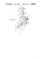
- FIG. 4 is a partially cut-away side view of the splicing unit only
- FIG. 5 is a plan view of the relationship between the splicing unit and the magazine
- FIG. 6 is a side view of only the splicing plate partially constituting the splicing unit
- FIG. 7 is a back view of the positional relationship between the splicing plate, the locking arm, and the locking cylinder;
- FIG. 8 is a side view illustrating the situation in which the joining preparation is presented to the end of the new roll of the web which is put on the splicing plate in the stand-by position, together with the cutting unit being located in the production position;
- FIG. 9 is a side view illustrating the splicing plate having the joining preparation completed in the stand-by position together with the cutting unit located in the production position;
- FIG. 10 is a side view of the situation in which the web being held in the splicing plate, which has been moved onto the production position, and the web being held in the cutting unit, are joined with each other;
- FIG. 11 is a side view of the situation in which both the webs are continuously fed out after being joined with each other;
- FIG. 12 is a front view illustrating the entire device with splicing units for supplying the packaging webs
- FIG. 13 is a schematic view taken from the side of FIG. 12;
- FIG. 14 is a schematic side view of the positional relationship between the driving roller, the braking roller, and the crease wheel during operation;
- FIG. 15 is a perspective view of the unit for detecting the position of the crease wheel by means of sensors
- FIG. 16 is a schematic side view of the positional relationship between the driving roller, the braking roller, and the crease wheel at their stops;
- FIG. 17 is a plan view of the packaging webs which have been joined with each other.
- FIG. 18-(a), 18-(b), and 18-(c) are plan views of the examples of joining states of the webs, in which all the parts are: (1) and (1'): web, (12): cutting unit, (121): cutting edge, (122): cutting plate, (123): clamp, (124): magnetic cylinder, (13): splicing plate, (131): axle, (132): pin, (133): locking arm, (134): locking hook, (14): pressure element, (A): magazine, (B), (B'), (B"): roll of web, and (C): splicing unit.
- the magazine (A) has a space large enough to house the two rolls of the packaging web (1) and has two pairs of left and right roll supporting articles (2) and (2) mounted on a supporting member (a) in the middle of the magazine (A) and on the left and right supporting member (a') and (a'), respectively.
- the magazine (A) can house the roll of the webs (B) and (B') in the left and right side-parts, respectively, of FIGS. 1 and 2, by means of a pair of left and right roll supporting articles (2) and (2) to hold a core of the roll of the packaging web (1).
- the right side-part of FIGS. 1 and 2 acts as the production position or on-line position in the production line, whereas the left side-part thereof acts as the stand-by position.
- the twin type magazine (A) is movable along a guide rail 3 in a longitudinal direction of FIGS. 1 and 2. Movement of the magazine (A) from the state shown in FIG. 1 in the right direction will allow the roll of the web to be positioned where the prior roll of the web (B) was previously positioned. Such movement will also allow the part in which the roll of the web (B) was housed to be positioned in the side location as sown by a two-dot chain line (B") in FIG. 1. In that case, without needing the magazine (A) to be of the twin type, an alternative may be two independent magazines capable of housing one roll of the web in each of them with an option of installing both the magazines, such that they are movable in a longitudinal directional along the guide rail (3).
- the magazine (A) having the aforementioned functions can be used when manufacturing a packaging container.
- the packaging web which is the raw material, is continuously fed out.
- the roll of the web (B) shown by a solid line in the right side of FIG. 12 is on the production line, i.e. at the production position, while another roll of the web (B') stands ready for processing in the stand-by position shown in the left side of the figure.
- the roll of the web (B) located on the production line, i.e. at the production position, is continuously fed out to a feeding unit constituted by a braking roller (4), a crease wheel (5), a driving roller (6), and a pressure roller (7).
- a feeding unit constituted by a braking roller (4), a crease wheel (5), a driving roller (6), and a pressure roller (7).
- the new roll of the web (B') can be adapted to be moved onto the production position by means of moving the magazine (A) in a right direction of FIGS. 1, 2, and 12, thereby permitting continuous manufacturing. Movement of the magazine (A) housing the two rolls in a right direction of FIGS. 1, 2, and 12, will result in the roll of the web which was housed in the prior production position to be located at the position at a side position shown by the two-dot chain line (B") of FIGS. 1 and 12. At position (B") adjacent the production position, the core and mandrel for the roll of the web (B) is removed and the new roll of the web to be subsequently used (B") is set.
- a roll of the web (B") can be adapted to stand ready for processing in the aforementioned position. Furthermore, upon becoming exhausted, the web (B') located in the production position is moved by moving the magazine (A) in a reverse direction to that for the last process, i.e. in the left direction. The aforementioned roll of the web (B") will then be in the middle production position, thereby enabling continued manufacturing.
- a repetition of such an operation makes it possible to supply the new roll of the web at once, after the roll of the web is exhausted in the production position.
- a detecting unit For example, a photocell can be used which detects the vicinity of the article for supporting the roll (2) in the magazine (A). A detection of the end of the roll of the web by such a detecting unit will allow easy detection of any impending exhaustion of the roll of the web located in the production position.
- the web (1) which is continuously fed out by means of the aforementioned feeding unit is cut into a blank sheet (1a) whose dimensional magnitude is equal to that of one unit of packaging container by a cutting unit (8) seen in FIG. 13.
- the cutting unit (8) comprises a pair of driving rollers (10) and (10) and a photosensor (9) which detects a bar-code mark on the surface of the web. Detection of the bar code will cause an indexing and in feed of the web and will cause a pair of cutting rollers (11) and (11) to cut the web (1) into the blank sheet (1a) equal in size to one unit of a packaging container.
- the splicing unit comprises a cutting unit (12) fixed to the upper end of the magazine (A), splicing plates (13) and (13) disposed on the left and right positions (corresponding to the production position and the stand-by position) on the upper part of the magazine (A), and a pressure element (14) shown in FIG. 4.
- the cutting unit (12) which is always located at the production position, comprises a cutting edge (121) capable of being moved in a longitudinal direction of FIGS. 5 and 12, a cutting plate (122) fixed partially to the body of the device, and a clamp (123) for fixing the web when the web is cut by the aforementioned cutting edge (121).
- a cutting edge (121) capable of being moved in a longitudinal direction of FIGS. 5 and 12, a cutting plate (122) fixed partially to the body of the device, and a clamp (123) for fixing the web when the web is cut by the aforementioned cutting edge (121).
- FIG. 9 while the web (1) being used is being pressed onto the cutting plate (122) by means of the clamp (123), the cutting edge (121) moves in a cross direction of the web (1) and enables the web (1) to be cut.
- rotation of a magnetic cylinder (124) moves the cutting edge (121) in a cross direction of the web (1).
- the web (1) has a sufficient length for crease lines (111)-(115) to extend across the web (1) with their fixed pattern being repeated.
- the range of the cutting unit (8) is indicated by (L) and is, therefore, equal in size to the blank sheet (1a) of one unit of the packaging container. Unless such a cutting process is made near the end of the web (1) being used, it difficult for the end of the web being used and the end of the next new roll of the web to be joined with each other for continuous manufacturing.
- the longer web (1) causes the crease lines (111)-(115) to form panels (101)-(105) so that the same pattern is repeated.
- the end of the web being used (1) and the end of the next new web (1') are joined with the help of auxiliary tape (18) to each other at a predetermined position in the crease pattern, i.e. at a position dividing the panel (102) of FIG. 17 into two equal portions.
- the crease wheel (5) shown in FIGS. 14-16 is part of the feeding unit for the web (1) so that the web may be fed out along a crease line while being folded.
- the crease wheel (5) is a rotational article equipped with edges (51)-(54) with the predetermined intervals left therebetween.
- the dimensions between the two corresponding edges of the four edges i.e. the dimensions between a pair of edges--(51) and (52), (52) and (53), and (53) and (54) will equal that of each of the panels (101) to (103) and the dimension between the edges (51) and (54) will equal 1 4 +1 5 , so that the panel (104) and the panel (105) act as a margin to be pasted.
- the blank sheet (1a) may be treated as one surface.
- the constant cutting of the end of the web (1) being used, made at the fixed position of the crease pattern, can be done while the crease wheel (5) is stopped at a predetermined rotational position.
- the web (1) is cut at the fixed position rearward of the aforementioned rotational position by means of the cutting unit (12) partially constituting the splicing unit (C).
- the feeding unit comprises the braking roller (4) equipped with an electromagnetic brake, the crease wheel (5) which feeds out the web (1) while folding the same along the crease lines (111)-(114) as referred to above, the driving roller (6) being driven by a motor, and the pressure roller (7).
- a rotating axle (55) of the crease wheel (5) is provided with a pin (56) which acts as a member to detect the rotational position thereof. This pin (56) extends from the external peripheral surface of the rotating axle (55).
- a sensor (15) is provided at a fixed position on the frame or the like to detect pin (56).
- the sensor (15) detects the top end part of the aforementioned pin (56).
- the top end part of the pin (56) is on a rotational locus drawn with the rotating axle (55) of the crease wheel (5) as a center.
- the mounting position of the sensor (15) allows it to detect the top end face of the pin (56).
- an alternative idea is for the sensor (15) to detect the side face of the top end part of the pin (56). Any number of arrangements can be used for the sensor (15) to detect the pin (56).
- the positional relationship between the braking roller (4), the driving roller (6), and the crease wheel (5) shows that the crease wheel (5) is pivotable about the braking roller (4).
- the crease wheel (5) will move by an angle, ⁇ , between the braking roller (4) and the driving roller (6).
- the tension of the web (1) ensures the folding of the creases, and the contact angle of the web with the braking roller (4) is large whereby sliding of the web during braking is avoided.
- the embodiment has the crease wheel (5) mounted to the top end part of an arm (16) which is pivotable about axle (41) at the center of the braking roller (4).
- the crease wheel (5) is positioned, as shown in FIG. 16 at a lifted position to allow the web (1) to be hung between the braking roller (4) and the driving roller (6) without being in contact with the crease wheel (5).
- the arm (16) is then adapted to be pivoted as shown by an arrow in FIG. 16 from the solid line to the dotted line position and then to the position as shown in FIG. 14.
- the two splicing plates (13) of the aforementioned cutting unit (12) constitute a part of the splicing unit (C).
- the splicing plates (13), as shown in FIG. 12, are provided on the two left and right positions (corresponding to the production position and the stand-by position) of the upper part of magazine (A).
- One splicing plate (13) enables the end of the web (1) being used in the production position (which is cut at the fixed position by the cutting unit (12), as mentioned above), and the end of the new roll of the web moved to the production position to be joined with each other, as well as enables the new joined web (1') to be fed forward.
- Another splicing plate (13) at the end of the new roll of the web to be subsequently used stands ready for processing in the stand-by position.
- this splicing plate (13) is pivotable as indicated in FIGS. 4, 6, 10, and 11, and FIGS. 8 and 9.
- the splicing plate (13) is pivotable about axle (131).
- FIG. 8 illustrates the case where the end part of the new roll of the web (B') to be subsequently used is held so that preparation for joining the aforementioned end thereof and the end of the web (1) located on the production position with each other may be performed.
- the splicing plate (13) is moved about the axle (131) and the end of the new roll of the web to be subsequently used is put on the face thereof.
- the cutting is manually made at its predetermined position, i.e. the cutting position (17) by utilizing an edge of the splicing plate (13).
- Half of the auxiliary tape (18) can be adhered to the cut part.
- the cutting position is the position dividing the panel (102) of FIG. 17 into two equal parts, as mentioned above.
- three pins (132) are provided on the splicing plate (13) such that they are vertically separable from the face thereof. As shown in FIG. 8, the three pins (132) extend from the left to right sides of the splicing plate (13). By holding the notched stage part of the roll of the web to be subsequently used by each of the pins (132) which extend from the face of the splicing plate (13), as shown in FIG. 17, the end of the web (1') to be cut can easily be determined.
- a clamp (138) is disposed on the splicing plate (13) by movement in the direction indicated by an arrow in FIG. 8 to press the end of the new web (1') on the splicing plate (13) so that said web (1') will not move. An arrangement is then made whereby the new web (1') is ready to be cut at its predetermined position.
- the aforementioned work can be performed at a position offset from the production line, it can be done concurrently with continued production on the production line.
- the splicing plate (13) is pivoted whereby the joining preparation in the stand-by position is finished.
- a locking arm (133) is rotatably mounted on the splicing plate (13).
- the locking arm (133) can move from the position as shown by solid lines in FIGS. 4 and 6 to the position shown by a chain line in FIG. 9.
- the locking arm (133) has a locking hook (134) mounted to the face of the splicing plate (13) and rotatable on the splicing plate (13) from the position shown by the solid line of FIG. 7 to a position as shown by the chain line of the same figure so that the pin (134a) may be inserted into a hole (135) to lock the splicing plate (13).
- Another hole (136) is provided on the locking arm (133). This hole (136) receives the pin (137a) of the locking cylinder (137) located in the production position.
- the splicing plate (13) is moved from the stand-by position to the production position, and furthermore, the splicing plate (13) is moved from the position shown in FIG. 9 to the position shown in FIGS. 10 and 11.
- the pin (137a) of the locking cylinder (137) is then fitted into the hole (136), as shown by the arrow of FIG. 7, by actuation of the locking cylinder (137).
- the locking arm (133) will then be locked in the production position. In that case, if the splicing plate (13) is locked to the locking arm (133), the splicing plate (13) located in the production position is also indirectly locked, whereby joining work can easily be performed in the production position, as will be discussed below.
- the splicing plate (13) stands ready for attaining the next function. While completing the preparation for the joining of the end of the new web (1'), a focus of the subsequent description is placed upon an arrangement in which when the web (1) in the production position is exhausted. Thereafter, lateral movement of the magazine (A) from the position as shown in FIG. 12 will cause the aforementioned splicing plate (13) to be moved toward the production position. Subsequently, the splicing plate (13) is adapted to be moved from the position of FIG. 9 to the vertical position as shown in FIGS. 10 and 11. Namely, as shown in FIG.
- the embodiment adapts the part of the web to be joined by the auxiliary tape (18) to be pressed once by the pressure element (14) so that this part is not separated.
- the cylinder (141) causes pivotable pressure element (14) to press the joining part.
- This cylinder (141) is pivotable about axle (131) of the splicing plate (13), as shown in FIG. 7.
- the clamp (138) presses the new web (1') against the splicing plate (13), and as shown in FIG. 11, if the clamp (138) and the pressure element (14) are returned to the original position, it enables the new web (1') to be fed out in a forward direction.
- the operation including the work of cutting the end part of the web (1) being used at its predetermined position by means of the cutting unit (12), the work for preparing to join the end of the new web (1') to the end of web (1'), the work of moving the roll of the web (1') onto the production position, and the work of joining both the webs (1) and (1') with each other are all interactively performed.
- This work is commenced when the end of the roll of the web (1) being used in the production position is encountered and/or when an operator desires a change in the type of web being used.
- the driving roller (6) which continuously feeds out the web (1) being used is switched from a high speed rotation to a low speed rotation.
- the sensor (15) is actuated, and upon the rotation of the crease wheel (5) to the solid line position of FIG. 14, the braking roller (4) is actuated so that the feed of the web (1) is stopped.
- Such an operation by the sensor (15) means that it is possible to accurately cut the web (1) at the proper position corresponding to the location of the cutting unit (12).
- the clamp (123) causes the web (1) which has been stopped to be pressed against the cutting plate (122) so that the vicinity of the end of the web (1) which is stopped on the cutting unit (12) is cut at the predetermined position.
- the part of the web (1) to be cut by the cutting edge (121) of the cutting unit (12) is also pressed against the splicing plate (13) by the clamp (138) of the splicing plate (13).
- the splicing unit may be applied when the webs (E) and (E) are different in width from each other in addition to the case when webs (E) and (E) having the same width as shown n FIG. 18-(a) are joined with each other.
- the joining is made while one-side margins are aligned with each other.
- the web (1) is located between the feeding-out unit comprising the braking roller (4), the crease wheel (5), the driving roller (6), and the pressing roller (7), and an introducing section to the cutting unit (8).
- the web (1) is provided with a sagging part (1b) dangling a predetermined distance.
- the lower end of the sagging part (1b) is detected by photocells (19) and (19) and control of the feeding speed of the feeding-out unit is possible by supplying an amount of the web adequate to the working speed of the subsequent process "cutting unit (8)".
- the web located between the feeding-unit and the subsequent process "cutting unit (8)" forms an approximately 90° angle of twist for the sagging part (1b) of the web.
- the weight of the web located in the sagging part (1b) acts to tension the feeding-out unit and the introducing section for subsequent processing so that sufficient force for pulling the web (1) for subsequent processing is available.
- one side margin of the introducing section of the web for the subsequent process is provided with a guide member (20).
- This guide member (20) catches the side margin (1c) of the web (1) so that aligning of webs different in width, as illustrated in FIGS. 18-(b) and 18-(c) can be done.
- the guide member (20) acts as a reference location for preventing the webs from wandering and twisting to ensure a smooth continuous running.
- a taper roller illustrated by a two-dot chain line prevents the web from floating and being twisted and adds a force for moving the web to the side of the guide member (20).
- the new roll of the web and the web located in the production position can be simply joined.
- the roll of the web which had undergone the joining preparation in the stand-by position is quickly transferred onto the production position. Not only is a decrease in manufacturing efficiency avoided, but also, a lot of labor for making a replacement between the webs is avoided.
Landscapes
- Replacement Of Web Rolls (AREA)
- Auxiliary Devices For And Details Of Packaging Control (AREA)
- Containers And Plastic Fillers For Packaging (AREA)
- Supplying Of Containers To The Packaging Station (AREA)
Applications Claiming Priority (2)
| Application Number | Priority Date | Filing Date | Title |
|---|---|---|---|
| JP62059262A JPH07102917B2 (ja) | 1987-03-14 | 1987-03-14 | 包装用ウエブの接続装置 |
| JP62-59262 | 1987-03-14 |
Publications (1)
| Publication Number | Publication Date |
|---|---|
| US4908091A true US4908091A (en) | 1990-03-13 |
Family
ID=13108281
Family Applications (1)
| Application Number | Title | Priority Date | Filing Date |
|---|---|---|---|
| US07/165,701 Expired - Lifetime US4908091A (en) | 1987-03-14 | 1988-03-08 | Splicing device for packaging webs |
Country Status (8)
| Country | Link |
|---|---|
| US (1) | US4908091A (fr) |
| EP (1) | EP0283086B1 (fr) |
| JP (1) | JPH07102917B2 (fr) |
| AT (1) | ATE94144T1 (fr) |
| AU (1) | AU605558B2 (fr) |
| CA (1) | CA1315306C (fr) |
| DE (1) | DE3883814T2 (fr) |
| ES (1) | ES2043779T3 (fr) |
Cited By (7)
| Publication number | Priority date | Publication date | Assignee | Title |
|---|---|---|---|---|
| US5330126A (en) * | 1992-04-10 | 1994-07-19 | James River Corporation Of Virginia | Cup sidewall stock unwind stand |
| WO1995034497A1 (fr) * | 1994-06-16 | 1995-12-21 | Fabio Perini S.P.A. | Dispositif d'echange automatique de rouleaux d'un materiau en bande |
| US5573626A (en) * | 1993-05-26 | 1996-11-12 | Minnesota Mining And Manufacturing Company | Tape supply and applicator system including a tape splicing mechanism |
| US6079661A (en) * | 1998-12-18 | 2000-06-27 | Paper Converting Machine Co. | Automatic splicer for unwinder |
| US20040060928A1 (en) * | 2001-02-02 | 2004-04-01 | Gyula Balla | Apparatus in the production of a package or a packaging material |
| CN109626064A (zh) * | 2018-12-20 | 2019-04-16 | 中融飞腾(北京)科技有限公司 | 用于锂电池正负极基材放收料的不停机换卷式模切机 |
| CN111433007A (zh) * | 2017-12-04 | 2020-07-17 | 利乐拉瓦尔集团及财务有限公司 | 卷材对准设备、具有卷材对准设备的包装机以及拼接方法 |
Families Citing this family (8)
| Publication number | Priority date | Publication date | Assignee | Title |
|---|---|---|---|---|
| EP0847947A1 (fr) * | 1996-12-11 | 1998-06-17 | PCD-Polymere Gesellschaft m.b.H. | Changeur automatique de bobines |
| GB9626769D0 (en) * | 1996-12-23 | 1997-02-12 | Ishida Seisakusho | Method of connecting strip-like film and connecting device thereof |
| DE19700570A1 (de) * | 1997-01-10 | 1998-07-16 | Danubia Petrochem Deutschland | Automatischer Rollenwechsler |
| EP1790596B1 (fr) * | 2000-05-01 | 2010-07-28 | Kimberly-Clark Worldwide, Inc. | Procédé et appareil pour dérouler des matériaux en bande |
| ES2226676T3 (es) * | 2000-08-31 | 2005-04-01 | TETRA LAVAL HOLDINGS & FINANCE S.A. | Un metodo para empalmar material estratificado para envasar productos alimenticios vertibles. |
| DE102017206549A1 (de) * | 2017-04-19 | 2018-10-25 | Robert Bosch Gmbh | Verbrauchsmaterialhandhabungsvorrichtung zu einem Transport und/oder zu einer Handhabung von zumindest einem Verbrauchsmaterial, insbesondere eines Verpackungsmaterials |
| WO2019145222A1 (fr) * | 2018-01-29 | 2019-08-01 | Tetra Laval Holdings & Finance S.A. | Unité de magasin pour machine à emballer, machine à emballer dotée d'une unité de magasin et procédé de chargement d'une unité de magasin |
| DE102019106214A1 (de) | 2019-03-12 | 2020-09-17 | Federal-Mogul Valvetrain Gmbh | Verfahren zur Herstellung eines Hohlventils für Verbrennungsmotoren |
Citations (5)
| Publication number | Priority date | Publication date | Assignee | Title |
|---|---|---|---|---|
| US3580757A (en) * | 1967-07-18 | 1971-05-25 | Niepmann & Co Maschf Fr | Web winding machines |
| US4081312A (en) * | 1976-01-14 | 1978-03-28 | Athos Cristiani | Paper tape splicer for cigarette makers |
| US4190483A (en) * | 1977-03-15 | 1980-02-26 | Compensating Tension Controls, Inc. | Butt splicer |
| US4392912A (en) * | 1980-04-15 | 1983-07-12 | Molins Limited | Bobbin changer for joining successive reels of web of the cigarette industry |
| US4629531A (en) * | 1983-12-28 | 1986-12-16 | Hiroshi Kataoka | Apparatus for joining sheet ends |
Family Cites Families (6)
| Publication number | Priority date | Publication date | Assignee | Title |
|---|---|---|---|---|
| US2998204A (en) * | 1958-06-30 | 1961-08-29 | Ibm | Continuous web feeding system |
| US4196662A (en) * | 1978-03-10 | 1980-04-08 | Adolph Gottscho, Inc. | Continuous feed hot leaf imprinter |
| DE3026995A1 (de) * | 1980-07-17 | 1982-02-11 | Focke & Co, 2810 Verden | Verfahren und vorrichtung zum aneinanderschliessen von verpackungsmaterial-bahnen in verpackungsmaschinen |
| US4386988A (en) * | 1981-05-04 | 1983-06-07 | Owens-Illinois, Inc. | Web handling apparatus |
| JPS5922841A (ja) * | 1982-07-28 | 1984-02-06 | Isowa Fuupaa Suifuto:Kk | ウエブスプライサ− |
| JPS59133553U (ja) * | 1983-02-24 | 1984-09-06 | 新明和工業株式会社 | フイルムの終端検出装置 |
-
1987
- 1987-03-14 JP JP62059262A patent/JPH07102917B2/ja not_active Expired - Lifetime
-
1988
- 1988-03-08 US US07/165,701 patent/US4908091A/en not_active Expired - Lifetime
- 1988-03-09 ES ES88200444T patent/ES2043779T3/es not_active Expired - Lifetime
- 1988-03-09 EP EP88200444A patent/EP0283086B1/fr not_active Expired - Lifetime
- 1988-03-09 DE DE88200444T patent/DE3883814T2/de not_active Expired - Lifetime
- 1988-03-09 AT AT88200444T patent/ATE94144T1/de not_active IP Right Cessation
- 1988-03-11 AU AU13011/88A patent/AU605558B2/en not_active Expired
- 1988-03-14 CA CA000561350A patent/CA1315306C/fr not_active Expired - Fee Related
Patent Citations (5)
| Publication number | Priority date | Publication date | Assignee | Title |
|---|---|---|---|---|
| US3580757A (en) * | 1967-07-18 | 1971-05-25 | Niepmann & Co Maschf Fr | Web winding machines |
| US4081312A (en) * | 1976-01-14 | 1978-03-28 | Athos Cristiani | Paper tape splicer for cigarette makers |
| US4190483A (en) * | 1977-03-15 | 1980-02-26 | Compensating Tension Controls, Inc. | Butt splicer |
| US4392912A (en) * | 1980-04-15 | 1983-07-12 | Molins Limited | Bobbin changer for joining successive reels of web of the cigarette industry |
| US4629531A (en) * | 1983-12-28 | 1986-12-16 | Hiroshi Kataoka | Apparatus for joining sheet ends |
Cited By (11)
| Publication number | Priority date | Publication date | Assignee | Title |
|---|---|---|---|---|
| US5330126A (en) * | 1992-04-10 | 1994-07-19 | James River Corporation Of Virginia | Cup sidewall stock unwind stand |
| US5573626A (en) * | 1993-05-26 | 1996-11-12 | Minnesota Mining And Manufacturing Company | Tape supply and applicator system including a tape splicing mechanism |
| WO1995034497A1 (fr) * | 1994-06-16 | 1995-12-21 | Fabio Perini S.P.A. | Dispositif d'echange automatique de rouleaux d'un materiau en bande |
| US5730389A (en) * | 1994-06-16 | 1998-03-24 | Fabio Perini S.P.A. | Device and method for the automatic exchange of reels of web material |
| US6079661A (en) * | 1998-12-18 | 2000-06-27 | Paper Converting Machine Co. | Automatic splicer for unwinder |
| US20040060928A1 (en) * | 2001-02-02 | 2004-04-01 | Gyula Balla | Apparatus in the production of a package or a packaging material |
| US6894256B2 (en) | 2001-02-02 | 2005-05-17 | Tetra Laval Holdings & Finance S.A. | Apparatus in the production of a package or a packaging material |
| CN111433007A (zh) * | 2017-12-04 | 2020-07-17 | 利乐拉瓦尔集团及财务有限公司 | 卷材对准设备、具有卷材对准设备的包装机以及拼接方法 |
| CN111433007B (zh) * | 2017-12-04 | 2022-09-06 | 利乐拉瓦尔集团及财务有限公司 | 卷材对准设备、具有卷材对准设备的包装机以及拼接方法 |
| US11535475B2 (en) * | 2017-12-04 | 2022-12-27 | Tetra Laval Holdings & Finance S.A. | Web alignment device, a packaging machine having a web alignment device and a splicing method |
| CN109626064A (zh) * | 2018-12-20 | 2019-04-16 | 中融飞腾(北京)科技有限公司 | 用于锂电池正负极基材放收料的不停机换卷式模切机 |
Also Published As
| Publication number | Publication date |
|---|---|
| CA1315306C (fr) | 1993-03-30 |
| ATE94144T1 (de) | 1993-09-15 |
| DE3883814D1 (de) | 1993-10-14 |
| EP0283086B1 (fr) | 1993-09-08 |
| ES2043779T3 (es) | 1994-01-01 |
| AU605558B2 (en) | 1991-01-17 |
| JPH07102917B2 (ja) | 1995-11-08 |
| AU1301188A (en) | 1988-09-15 |
| JPS63225056A (ja) | 1988-09-20 |
| DE3883814T2 (de) | 1994-01-13 |
| EP0283086A3 (en) | 1990-02-28 |
| EP0283086A2 (fr) | 1988-09-21 |
Similar Documents
| Publication | Publication Date | Title |
|---|---|---|
| AU605558B2 (en) | Splicing device for packaging webs | |
| US4588463A (en) | Method of producing a reinforced file folder | |
| US5518202A (en) | Process and apparatus for connecting material webs, in particular of packaging material | |
| JPS5931244A (ja) | 給紙装置の紙継ぎ方法 | |
| KR20000052387A (ko) | 종이웨브의 접속부형성장치와 방법 | |
| DE4108693C2 (de) | Abwickelmaschine für aufgerolltes Bahnenmaterial | |
| US4289556A (en) | Method and apparatus for splicing folded paper | |
| JP2584002B2 (ja) | 紡機の自動スライバ継ぎ方法 | |
| JPS62157160A (ja) | 印刷機の給紙部 | |
| EP0585092B1 (fr) | Enrouleuse automatique pour produits en forme de ruban | |
| EP0810947B1 (fr) | Dispositif et procede pour machine a envelopper | |
| JP4342015B2 (ja) | ラベル供給装置 | |
| JPH0688698B2 (ja) | 印刷機の全自動給紙方法および装置 | |
| JPH05302B2 (fr) | ||
| JPS60161854A (ja) | ウェブ継合わせ方法および装置 | |
| JP2663169B2 (ja) | 給紙装置へのロール原反供給方法及び装置 | |
| JPH0211493B2 (fr) | ||
| JPH0638834Y2 (ja) | スプライサーの原紙切断装置 | |
| JP3563683B2 (ja) | フィルム接合装置 | |
| JPH08319046A (ja) | 紙通し装置 | |
| JPH06247597A (ja) | 紙継ぎ方法およびこれを実施する原紙供給装置 | |
| JP2887017B2 (ja) | 連続搬送装置 | |
| JP2995365B2 (ja) | 巻取機における製品テープの巻取方法と製品ガイド | |
| JPH06226880A (ja) | タイヤ成形機における帯状材料貼付成形方法 | |
| JPH0511247Y2 (fr) |
Legal Events
| Date | Code | Title | Description |
|---|---|---|---|
| AS | Assignment |
Owner name: AB TETRA PAK, BOX 61, 221 00 LUND SWEDEN Free format text: ASSIGNMENT OF ASSIGNORS INTEREST.;ASSIGNORS:TRAEGAARDH, PAUL;NANTIN, HANS;REEL/FRAME:004866/0781;SIGNING DATES FROM 19880215 TO 19880302 Owner name: AB TETRA PAK,SWEDEN Free format text: ASSIGNMENT OF ASSIGNORS INTEREST;ASSIGNORS:TRAEGAARDH, PAUL;NANTIN, HANS;SIGNING DATES FROM 19880215 TO 19880302;REEL/FRAME:004866/0781 |
|
| STCF | Information on status: patent grant |
Free format text: PATENTED CASE |
|
| FEPP | Fee payment procedure |
Free format text: PAYOR NUMBER ASSIGNED (ORIGINAL EVENT CODE: ASPN); ENTITY STATUS OF PATENT OWNER: LARGE ENTITY |
|
| FPAY | Fee payment |
Year of fee payment: 4 |
|
| FEPP | Fee payment procedure |
Free format text: PAYER NUMBER DE-ASSIGNED (ORIGINAL EVENT CODE: RMPN); ENTITY STATUS OF PATENT OWNER: LARGE ENTITY Free format text: PAYOR NUMBER ASSIGNED (ORIGINAL EVENT CODE: ASPN); ENTITY STATUS OF PATENT OWNER: LARGE ENTITY |
|
| FPAY | Fee payment |
Year of fee payment: 8 |
|
| FPAY | Fee payment |
Year of fee payment: 12 |