US5234155A - Wire bonding method and apparatus - Google Patents
Wire bonding method and apparatus Download PDFInfo
- Publication number
- US5234155A US5234155A US07/870,461 US87046192A US5234155A US 5234155 A US5234155 A US 5234155A US 87046192 A US87046192 A US 87046192A US 5234155 A US5234155 A US 5234155A
- Authority
- US
- United States
- Prior art keywords
- wire
- linear motor
- movable member
- clamping
- clamper
- Prior art date
- Legal status (The legal status is an assumption and is not a legal conclusion. Google has not performed a legal analysis and makes no representation as to the accuracy of the status listed.)
- Expired - Fee Related
Links
Images

Classifications
-
- H—ELECTRICITY
- H10—SEMICONDUCTOR DEVICES; ELECTRIC SOLID-STATE DEVICES NOT OTHERWISE PROVIDED FOR
- H10W—GENERIC PACKAGES, INTERCONNECTIONS, CONNECTORS OR OTHER CONSTRUCTIONAL DETAILS OF DEVICES COVERED BY CLASS H10
- H10W72/00—Interconnections or connectors in packages
- H10W72/071—Connecting or disconnecting
- H10W72/0711—Apparatus therefor
-
- H—ELECTRICITY
- H05—ELECTRIC TECHNIQUES NOT OTHERWISE PROVIDED FOR
- H05K—PRINTED CIRCUITS; CASINGS OR CONSTRUCTIONAL DETAILS OF ELECTRIC APPARATUS; MANUFACTURE OF ASSEMBLAGES OF ELECTRICAL COMPONENTS
- H05K13/00—Apparatus or processes specially adapted for manufacturing or adjusting assemblages of electric components
- H05K13/06—Wiring by machine
-
- H—ELECTRICITY
- H10—SEMICONDUCTOR DEVICES; ELECTRIC SOLID-STATE DEVICES NOT OTHERWISE PROVIDED FOR
- H10W—GENERIC PACKAGES, INTERCONNECTIONS, CONNECTORS OR OTHER CONSTRUCTIONAL DETAILS OF DEVICES COVERED BY CLASS H10
- H10W72/00—Interconnections or connectors in packages
- H10W72/071—Connecting or disconnecting
- H10W72/075—Connecting or disconnecting of bond wires
-
- H—ELECTRICITY
- H10—SEMICONDUCTOR DEVICES; ELECTRIC SOLID-STATE DEVICES NOT OTHERWISE PROVIDED FOR
- H10W—GENERIC PACKAGES, INTERCONNECTIONS, CONNECTORS OR OTHER CONSTRUCTIONAL DETAILS OF DEVICES COVERED BY CLASS H10
- H10W72/00—Interconnections or connectors in packages
- H10W72/071—Connecting or disconnecting
- H10W72/0711—Apparatus therefor
- H10W72/07168—Means for storing or moving the material for the connector
-
- H—ELECTRICITY
- H10—SEMICONDUCTOR DEVICES; ELECTRIC SOLID-STATE DEVICES NOT OTHERWISE PROVIDED FOR
- H10W—GENERIC PACKAGES, INTERCONNECTIONS, CONNECTORS OR OTHER CONSTRUCTIONAL DETAILS OF DEVICES COVERED BY CLASS H10
- H10W72/00—Interconnections or connectors in packages
- H10W72/071—Connecting or disconnecting
- H10W72/075—Connecting or disconnecting of bond wires
- H10W72/07502—Connecting or disconnecting of bond wires using an auxiliary member
-
- H—ELECTRICITY
- H10—SEMICONDUCTOR DEVICES; ELECTRIC SOLID-STATE DEVICES NOT OTHERWISE PROVIDED FOR
- H10W—GENERIC PACKAGES, INTERCONNECTIONS, CONNECTORS OR OTHER CONSTRUCTIONAL DETAILS OF DEVICES COVERED BY CLASS H10
- H10W72/00—Interconnections or connectors in packages
- H10W72/071—Connecting or disconnecting
- H10W72/075—Connecting or disconnecting of bond wires
- H10W72/07531—Techniques
- H10W72/07532—Compression bonding, e.g. thermocompression bonding
- H10W72/07533—Ultrasonic bonding, e.g. thermosonic bonding
Definitions
- the present invention relates to a wire bonding method and apparatus and more particularly to a wire clamper driving method and apparatus.
- One of conventionally known wire clampers that clamp bonding wires is comprised of an immovable member and a movable member.
- the movable member is moved by an electromagnet so that the wire clamper is opened and closed, as described, for example, in Japanese Patent Application Laid-Open No. 56-7443.
- a certain minimum amount of electric power is required to drive the movable member of the wire clamper.
- An electric power is also required to keep clamping the bonding wire.
- the wire is pressed against the immovable member by a movable member that is moved by a predetermined amount of electric power which is necessary to obtain the driving force and the clamping force of the movable member. Therefore, the drawback is that clamping scars are formed on the wire since the movable member strikes the wire before it clamps the wire.
- the object of the present invention is to provide a wire bonding method and apparatus which can prevent clamping scars.
- the method of the present invention which achieves the object described above is characterized in that: the method uses a wire clamper which comprises an immovable member and a movable member which is driven by a linear motor, the linear motor is actuated by an electric power so that the movable member is moved in the direction of clamping the wire when the wire clamping process is started, then the linear motor is switched off or actuated in the direction which opens the clamper, and then again the linear motor is actuated in the direction of clamping.
- the apparatus of the present invention is characterized in that it comprises: a wire clamper having an immovable member and a movable member for clamping a wire; a linear motor which opens and closes the wire clamper; a linear motor driving circuit which drives the linear motor; and a control circuit which outputs signals at the time of wire clamping so that the linear motor is actuated in the direction of clamping, then switched off or actuated in the direction to open the clamper, and then again actuated in the direction of clamping.
- the linear motor is first actuated so that the movable member is moved in the direction of making a clamp of the wire, then the linear motor is switched off or is actuated so as to move the movable member in the opposite direction, thus slowing down the moving speed of the movable member so that the movable member comes into contact with the wire at a low speed.
- the linear motor is again actuated in the direction of clamping the wire, so that the movable member clamps the wire by the power caused by the linear motor.
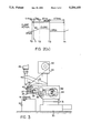
- FIG. 1 is a plan view which illustrates one embodiment of the present invention
- FIG. 2(a) is a chart of the applied current timing used in the present invention.
- FIG. 2(b) is a diagram of the clamper action in the present invention.
- FIG. 3 is a side view of a wire bonding apparatus of the present invention.
- FIG. 3 shows a wire bonding apparatus of the present invention.
- An X-Y table 31 driven in the X and Y directions is mounted on a stand 30, and a bonding head 32 is fastened to the X-Y table 31.
- a lifter arm 33 that can be moved in the vertical direction is provided in the bonding head 32, and the lifter arm 33 is raised and lowered by a motor 34.
- a tool arm 36 for holding a capillary 35 is fastened to the lifter arm 33, and a clamper support 38 used for holding a wire cutting clamper 37 is also fastened to the lifter arm 33.
- the clamper support 41 has a wire supporting clamper that supports the wire 39 lightly
- the spool support 43 has a spool 42 on which the wire 39 is wound
- the camera support 46 has a camera 45 that detects a sample 44.
- the wire 39 that is supplied from the spool 42 to the sample 44 passes through a wire holding clamper 40, the wire cutting clamper 37, and the capillary 35.
- numeral 50 indicates a feeder which feeds the sample 44
- numeral 51 indicates guide rails which guide the sample 44.
- the wire cutting clamper 37 is provided on a clamper support 1 (which is referred to by numeral 38 in FIG. 3).
- a fixed arm 3 which has an immovable member 2 is fastened to the clamper support 1, and a movable arm 5 is pivotally provided on the clamper support 1 by a supporting shaft 4 so that a movable member 6 faces the immovable member 2.
- a linear motor 7 is provided on the clamper support 1 and comprised of a coil side 7a and a core side 7b.
- the coil side 7a is fastened to one end of the movable arm 5, and the core side 7b of the linear motor 7 is fastened to the clamper support 1.
- the movable arm 5 is urged by a spring 8 so that the movable member 5 comes into contact with the immovable member 2.
- the spring 8 has an extremely weak spring force.
- a stopper 9 which regulates the amount of opening of the movable member 6 is installed on the clamper support 1.
- Signals from a control circuit 10 that consists of a microcomputer, etc., are inputted into the linear motor 7 via a linear motor driving circuit 11.
- a program is stored in the control circuit 10.
- the program controls a current so as to be outputted from the linear motor driving circuit 11 to the linear motor 7 with a timing as shown in FIG. 2(a).
- FIG. 2(a) a clamper closing action is shown in the interval from T0 to T3, and a clamper opening action is shown in the interval from T3 to T4.
- a plus current is applied for T1 seconds (approximately 0.4 ms) as indicated by a numeral 20. Afterward, the current is switched off till T2 (for approximately 1.7 ms) as indicated by numeral 21. Then, a plus current is again applied between T2 and T3 (for approximately 20 ms) as shown by numeral 23.
- the clamping action of the wire 12 is accomplished in the following manner:
- the movable arm 5 is moved so that the movable member 6 provided on the movable arm 5 comes into contact with the immovable member 2 when the plus current is applied to the linear motor 2 as indicated by numeral 20.
- this plus current application 20 is performed for an extremely short period of time; as a result, the movable arm 5 is moved by inertia or by an extremely weak driving force of the spring 8 immediately after the movable arm 5 is driven.
- the movable arm 5 is driven at a low speed as referred to by numeral 30 in FIG. 2(b). Accordingly, the movable member 6 presses the wire 12 against the immovable member 2 at a low speed 30. Thus, wire scars are prevented. Then, as a result of the subsequent application as referred to as numeral 22 of a plus current, the wire 12 is clamped between the fixed arm 3 and movable member 6.
- the wire clamping action is performed during, for example, a cutting action of the wire after the completion of bonding to a second bonding point or after a formation of a ball at the tip of bonding wire, etc. Accordingly, the duration of the plus current application 22 is set based upon the time required for cutting the wire 12 or the time required for ball formation at the tip of the wire 12, etc.
- the coil side 7a of the linear motor 7 is fastened to the movable arm 5, and the core side 7b is fastened to the clamper support 1.
- the coil side 7a can be fastened to the clamper support 1, and the core side 7b to the movable arm 5.
- the movable member 6 is first moved by the actuation of the linear motor 7 in the direction of clamping, after which the driving force of the movable member 6 is weakened by switching off the power or actuating the linear motor 7 in the direction which opens the clamper, so that the movable member 6 strikes the wire 12 gently.
- the movable member 6 clamps the wire 12 as a result of this driving force.
- the movable member 6 strikes the wire 12 at a low speed, wire scars are prevented.
- the movable member 6 clamps the wire 12 as a result of a driving force applied after the movable member 6 has contacted the wire 12, an appropriate clamping force is obtainable.
- the linear motor is actuated so that the movable member is moved toward the immovable member, immediately after the linear motor is actuated, a switching off of the power or an actuation of the linear motor so that the movable member is moved toward the original position is performed, then after the movable member is contacted to the wire, the linear motor is actuated so that the movable member is moved in the direction of clamping.
- the movable member contacts the wire lightly and holds the wire securely, so that wire scars are prevented, and the wire is clamped with an appropriate clamping force.
Landscapes
- Engineering & Computer Science (AREA)
- Manufacturing & Machinery (AREA)
- Microelectronics & Electronic Packaging (AREA)
- Wire Bonding (AREA)
Applications Claiming Priority (2)
| Application Number | Priority Date | Filing Date | Title |
|---|---|---|---|
| JP3-113825 | 1991-04-19 | ||
| JP3113825A JPH04320349A (ja) | 1991-04-19 | 1991-04-19 | ワイヤボンデイング方法及び装置 |
Publications (1)
| Publication Number | Publication Date |
|---|---|
| US5234155A true US5234155A (en) | 1993-08-10 |
Family
ID=14621993
Family Applications (1)
| Application Number | Title | Priority Date | Filing Date |
|---|---|---|---|
| US07/870,461 Expired - Fee Related US5234155A (en) | 1991-04-19 | 1992-04-16 | Wire bonding method and apparatus |
Country Status (3)
| Country | Link |
|---|---|
| US (1) | US5234155A (ja) |
| JP (1) | JPH04320349A (ja) |
| KR (1) | KR960002993B1 (ja) |
Cited By (4)
| Publication number | Priority date | Publication date | Assignee | Title |
|---|---|---|---|---|
| DE19538397A1 (de) * | 1995-08-15 | 1997-02-20 | Hesse & Knipps Gmbh | Fadenklammer |
| WO2000002694A1 (en) * | 1998-07-10 | 2000-01-20 | Palomar Technologies, Inc. | Bond head having dual axes of motion |
| US8540136B1 (en) * | 2012-09-06 | 2013-09-24 | Taiwan Semiconductor Manufacturing Company, Ltd. | Methods for stud bump formation and apparatus for performing the same |
| US11420287B2 (en) * | 2019-09-29 | 2022-08-23 | Ningbo Shangjin Automation Technology Co., Ltd. | Wire clamping system for fully automatic wire bonding machine |
Families Citing this family (1)
| Publication number | Priority date | Publication date | Assignee | Title |
|---|---|---|---|---|
| JP4883017B2 (ja) * | 2008-01-24 | 2012-02-22 | 株式会社安川電機 | 基板把持装置およびそれを備えた基板搬送ロボット、半導体製造装置 |
Citations (2)
| Publication number | Priority date | Publication date | Assignee | Title |
|---|---|---|---|---|
| JPS567443A (en) * | 1979-06-29 | 1981-01-26 | Hitachi Ltd | Wire bonder |
| US5037023A (en) * | 1988-11-28 | 1991-08-06 | Hitachi, Ltd. | Method and apparatus for wire bonding |
-
1991
- 1991-04-19 JP JP3113825A patent/JPH04320349A/ja active Pending
-
1992
- 1992-04-15 KR KR1019920006260A patent/KR960002993B1/ko not_active Expired - Fee Related
- 1992-04-16 US US07/870,461 patent/US5234155A/en not_active Expired - Fee Related
Patent Citations (2)
| Publication number | Priority date | Publication date | Assignee | Title |
|---|---|---|---|---|
| JPS567443A (en) * | 1979-06-29 | 1981-01-26 | Hitachi Ltd | Wire bonder |
| US5037023A (en) * | 1988-11-28 | 1991-08-06 | Hitachi, Ltd. | Method and apparatus for wire bonding |
Cited By (6)
| Publication number | Priority date | Publication date | Assignee | Title |
|---|---|---|---|---|
| DE19538397A1 (de) * | 1995-08-15 | 1997-02-20 | Hesse & Knipps Gmbh | Fadenklammer |
| WO2000002694A1 (en) * | 1998-07-10 | 2000-01-20 | Palomar Technologies, Inc. | Bond head having dual axes of motion |
| US8540136B1 (en) * | 2012-09-06 | 2013-09-24 | Taiwan Semiconductor Manufacturing Company, Ltd. | Methods for stud bump formation and apparatus for performing the same |
| US8936730B2 (en) | 2012-09-06 | 2015-01-20 | Taiwan Semiconductor Manufacturing Company, Ltd. | Methods for forming apparatus for stud bump formation |
| US9498851B2 (en) | 2012-09-06 | 2016-11-22 | Taiwan Semiconductor Manufacturing Company, Ltd. | Methods for forming apparatus for stud bump formation |
| US11420287B2 (en) * | 2019-09-29 | 2022-08-23 | Ningbo Shangjin Automation Technology Co., Ltd. | Wire clamping system for fully automatic wire bonding machine |
Also Published As
| Publication number | Publication date |
|---|---|
| KR960002993B1 (ko) | 1996-03-02 |
| JPH04320349A (ja) | 1992-11-11 |
| KR920020661A (ko) | 1992-11-21 |
Similar Documents
| Publication | Publication Date | Title |
|---|---|---|
| JPH0245337B2 (ja) | ||
| JPS60223137A (ja) | 増加したボンデイング表面積を有するリ−ドワイヤボンデイング | |
| US5234155A (en) | Wire bonding method and apparatus | |
| US5297722A (en) | Wire bonding method and apparatus | |
| JP2925469B2 (ja) | 自動巻線機 | |
| US6533158B2 (en) | Wire bonding apparatus having wire clamp | |
| JPH06291161A (ja) | ワイヤボンディング装置 | |
| JPS61280700A (ja) | チツプ状電子部品の吸着装置 | |
| JP2894344B1 (ja) | ワイヤボンディング方法 | |
| JP2002158254A (ja) | ワイヤボンディング装置におけるワイヤクランプ機構の制御方法 | |
| JP2627968B2 (ja) | 半導体組立装置 | |
| JPS6229897B2 (ja) | ||
| JPS59181027A (ja) | ワイヤボンデイング装置 | |
| JPS6333295B2 (ja) | ||
| JP2539963B2 (ja) | ワイヤボンディング装置及びワイヤボンディング方法 | |
| JPS61179548A (ja) | ワイヤボンデイング装置 | |
| JPH0222993Y2 (ja) | ||
| JP2531667B2 (ja) | インナ−リ−ドボンダ | |
| US20080174132A1 (en) | Soft touch clamp actuation mechanism | |
| JP2725102B2 (ja) | ワイヤボンディング方法 | |
| JPS6084829A (ja) | ワイヤボンデイング装置 | |
| JPH0220833Y2 (ja) | ||
| JP3800957B2 (ja) | 線材接合装置 | |
| JPH06244234A (ja) | ワイヤボンダ | |
| JP2663193B2 (ja) | 半導体組立装置並びにその方法 |
Legal Events
| Date | Code | Title | Description |
|---|---|---|---|
| AS | Assignment |
Owner name: KABUSHIKI KAISHA SHINKAWA, JAPAN Free format text: ASSIGNMENT OF ASSIGNORS INTEREST.;ASSIGNORS:TAKAHASHI, KUNIYUKI;TORIHARA, MINORU;REEL/FRAME:006191/0849 Effective date: 19920521 |
|
| FPAY | Fee payment |
Year of fee payment: 4 |
|
| FEPP | Fee payment procedure |
Free format text: PAYOR NUMBER ASSIGNED (ORIGINAL EVENT CODE: ASPN); ENTITY STATUS OF PATENT OWNER: SMALL ENTITY |
|
| FPAY | Fee payment |
Year of fee payment: 8 |
|
| REMI | Maintenance fee reminder mailed | ||
| LAPS | Lapse for failure to pay maintenance fees | ||
| STCH | Information on status: patent discontinuation |
Free format text: PATENT EXPIRED DUE TO NONPAYMENT OF MAINTENANCE FEES UNDER 37 CFR 1.362 |
|
| FP | Lapsed due to failure to pay maintenance fee |
Effective date: 20050810 |