WO1998029257A1 - Support d'enregistrement optique - Google Patents
Support d'enregistrement optique Download PDFInfo
- Publication number
- WO1998029257A1 WO1998029257A1 PCT/JP1997/004735 JP9704735W WO9829257A1 WO 1998029257 A1 WO1998029257 A1 WO 1998029257A1 JP 9704735 W JP9704735 W JP 9704735W WO 9829257 A1 WO9829257 A1 WO 9829257A1
- Authority
- WO
- WIPO (PCT)
- Prior art keywords
- group
- recording medium
- recording layer
- azo
- optical recording
- Prior art date
- Legal status (The legal status is an assumption and is not a legal conclusion. Google has not performed a legal analysis and makes no representation as to the accuracy of the status listed.)
- Ceased
Links
Classifications
-
- G—PHYSICS
- G11—INFORMATION STORAGE
- G11B—INFORMATION STORAGE BASED ON RELATIVE MOVEMENT BETWEEN RECORD CARRIER AND TRANSDUCER
- G11B7/00—Recording or reproducing by optical means, e.g. recording using a thermal beam of optical radiation by modifying optical properties or the physical structure, reproducing using an optical beam at lower power by sensing optical properties; Record carriers therefor
- G11B7/24—Record carriers characterised by shape, structure or physical properties, or by the selection of the material
- G11B7/241—Record carriers characterised by shape, structure or physical properties, or by the selection of the material characterised by the selection of the material
- G11B7/242—Record carriers characterised by shape, structure or physical properties, or by the selection of the material characterised by the selection of the material of recording layers
- G11B7/244—Record carriers characterised by shape, structure or physical properties, or by the selection of the material characterised by the selection of the material of recording layers comprising organic materials only
- G11B7/246—Record carriers characterised by shape, structure or physical properties, or by the selection of the material characterised by the selection of the material of recording layers comprising organic materials only containing dyes
- G11B7/247—Record carriers characterised by shape, structure or physical properties, or by the selection of the material characterised by the selection of the material of recording layers comprising organic materials only containing dyes methine or polymethine dyes
- G11B7/2472—Record carriers characterised by shape, structure or physical properties, or by the selection of the material characterised by the selection of the material of recording layers comprising organic materials only containing dyes methine or polymethine dyes cyanine
-
- G—PHYSICS
- G11—INFORMATION STORAGE
- G11B—INFORMATION STORAGE BASED ON RELATIVE MOVEMENT BETWEEN RECORD CARRIER AND TRANSDUCER
- G11B7/00—Recording or reproducing by optical means, e.g. recording using a thermal beam of optical radiation by modifying optical properties or the physical structure, reproducing using an optical beam at lower power by sensing optical properties; Record carriers therefor
- G11B7/24—Record carriers characterised by shape, structure or physical properties, or by the selection of the material
- G11B7/241—Record carriers characterised by shape, structure or physical properties, or by the selection of the material characterised by the selection of the material
- G11B7/242—Record carriers characterised by shape, structure or physical properties, or by the selection of the material characterised by the selection of the material of recording layers
- G11B7/244—Record carriers characterised by shape, structure or physical properties, or by the selection of the material characterised by the selection of the material of recording layers comprising organic materials only
- G11B7/246—Record carriers characterised by shape, structure or physical properties, or by the selection of the material characterised by the selection of the material of recording layers comprising organic materials only containing dyes
- G11B7/2467—Record carriers characterised by shape, structure or physical properties, or by the selection of the material characterised by the selection of the material of recording layers comprising organic materials only containing dyes azo-dyes
-
- G—PHYSICS
- G11—INFORMATION STORAGE
- G11B—INFORMATION STORAGE BASED ON RELATIVE MOVEMENT BETWEEN RECORD CARRIER AND TRANSDUCER
- G11B7/00—Recording or reproducing by optical means, e.g. recording using a thermal beam of optical radiation by modifying optical properties or the physical structure, reproducing using an optical beam at lower power by sensing optical properties; Record carriers therefor
- G11B7/24—Record carriers characterised by shape, structure or physical properties, or by the selection of the material
- G11B7/241—Record carriers characterised by shape, structure or physical properties, or by the selection of the material characterised by the selection of the material
- G11B7/242—Record carriers characterised by shape, structure or physical properties, or by the selection of the material characterised by the selection of the material of recording layers
- G11B7/244—Record carriers characterised by shape, structure or physical properties, or by the selection of the material characterised by the selection of the material of recording layers comprising organic materials only
- G11B7/246—Record carriers characterised by shape, structure or physical properties, or by the selection of the material characterised by the selection of the material of recording layers comprising organic materials only containing dyes
- G11B7/248—Record carriers characterised by shape, structure or physical properties, or by the selection of the material characterised by the selection of the material of recording layers comprising organic materials only containing dyes porphines; azaporphines, e.g. phthalocyanines
-
- G—PHYSICS
- G11—INFORMATION STORAGE
- G11B—INFORMATION STORAGE BASED ON RELATIVE MOVEMENT BETWEEN RECORD CARRIER AND TRANSDUCER
- G11B7/00—Recording or reproducing by optical means, e.g. recording using a thermal beam of optical radiation by modifying optical properties or the physical structure, reproducing using an optical beam at lower power by sensing optical properties; Record carriers therefor
- G11B7/24—Record carriers characterised by shape, structure or physical properties, or by the selection of the material
- G11B7/241—Record carriers characterised by shape, structure or physical properties, or by the selection of the material characterised by the selection of the material
- G11B7/242—Record carriers characterised by shape, structure or physical properties, or by the selection of the material characterised by the selection of the material of recording layers
- G11B7/244—Record carriers characterised by shape, structure or physical properties, or by the selection of the material characterised by the selection of the material of recording layers comprising organic materials only
- G11B7/249—Record carriers characterised by shape, structure or physical properties, or by the selection of the material characterised by the selection of the material of recording layers comprising organic materials only containing organometallic compounds
- G11B7/2495—Record carriers characterised by shape, structure or physical properties, or by the selection of the material characterised by the selection of the material of recording layers comprising organic materials only containing organometallic compounds as anions
-
- G—PHYSICS
- G11—INFORMATION STORAGE
- G11B—INFORMATION STORAGE BASED ON RELATIVE MOVEMENT BETWEEN RECORD CARRIER AND TRANSDUCER
- G11B7/00—Recording or reproducing by optical means, e.g. recording using a thermal beam of optical radiation by modifying optical properties or the physical structure, reproducing using an optical beam at lower power by sensing optical properties; Record carriers therefor
- G11B7/24—Record carriers characterised by shape, structure or physical properties, or by the selection of the material
- G11B7/241—Record carriers characterised by shape, structure or physical properties, or by the selection of the material characterised by the selection of the material
- G11B7/242—Record carriers characterised by shape, structure or physical properties, or by the selection of the material characterised by the selection of the material of recording layers
- G11B7/244—Record carriers characterised by shape, structure or physical properties, or by the selection of the material characterised by the selection of the material of recording layers comprising organic materials only
- G11B7/246—Record carriers characterised by shape, structure or physical properties, or by the selection of the material characterised by the selection of the material of recording layers comprising organic materials only containing dyes
- G11B2007/24612—Record carriers characterised by shape, structure or physical properties, or by the selection of the material characterised by the selection of the material of recording layers comprising organic materials only containing dyes two or more dyes in one layer
-
- G—PHYSICS
- G11—INFORMATION STORAGE
- G11B—INFORMATION STORAGE BASED ON RELATIVE MOVEMENT BETWEEN RECORD CARRIER AND TRANSDUCER
- G11B7/00—Recording or reproducing by optical means, e.g. recording using a thermal beam of optical radiation by modifying optical properties or the physical structure, reproducing using an optical beam at lower power by sensing optical properties; Record carriers therefor
- G11B7/24—Record carriers characterised by shape, structure or physical properties, or by the selection of the material
- G11B7/241—Record carriers characterised by shape, structure or physical properties, or by the selection of the material characterised by the selection of the material
- G11B7/242—Record carriers characterised by shape, structure or physical properties, or by the selection of the material characterised by the selection of the material of recording layers
- G11B7/244—Record carriers characterised by shape, structure or physical properties, or by the selection of the material characterised by the selection of the material of recording layers comprising organic materials only
- G11B7/246—Record carriers characterised by shape, structure or physical properties, or by the selection of the material characterised by the selection of the material of recording layers comprising organic materials only containing dyes
- G11B2007/24618—Record carriers characterised by shape, structure or physical properties, or by the selection of the material characterised by the selection of the material of recording layers comprising organic materials only containing dyes two or more dyes in two or more different layers, e.g. one dye absorbing at 405 nm in layer one and a different dye absorbing at 650 nm in layer two
-
- G—PHYSICS
- G11—INFORMATION STORAGE
- G11B—INFORMATION STORAGE BASED ON RELATIVE MOVEMENT BETWEEN RECORD CARRIER AND TRANSDUCER
- G11B7/00—Recording or reproducing by optical means, e.g. recording using a thermal beam of optical radiation by modifying optical properties or the physical structure, reproducing using an optical beam at lower power by sensing optical properties; Record carriers therefor
- G11B7/24—Record carriers characterised by shape, structure or physical properties, or by the selection of the material
- G11B7/241—Record carriers characterised by shape, structure or physical properties, or by the selection of the material characterised by the selection of the material
- G11B7/242—Record carriers characterised by shape, structure or physical properties, or by the selection of the material characterised by the selection of the material of recording layers
- G11B7/244—Record carriers characterised by shape, structure or physical properties, or by the selection of the material characterised by the selection of the material of recording layers comprising organic materials only
- G11B7/249—Record carriers characterised by shape, structure or physical properties, or by the selection of the material characterised by the selection of the material of recording layers comprising organic materials only containing organometallic compounds
- G11B2007/2491—Record carriers characterised by shape, structure or physical properties, or by the selection of the material characterised by the selection of the material of recording layers comprising organic materials only containing organometallic compounds as anion
-
- G—PHYSICS
- G11—INFORMATION STORAGE
- G11B—INFORMATION STORAGE BASED ON RELATIVE MOVEMENT BETWEEN RECORD CARRIER AND TRANSDUCER
- G11B7/00—Recording or reproducing by optical means, e.g. recording using a thermal beam of optical radiation by modifying optical properties or the physical structure, reproducing using an optical beam at lower power by sensing optical properties; Record carriers therefor
- G11B7/24—Record carriers characterised by shape, structure or physical properties, or by the selection of the material
- G11B7/241—Record carriers characterised by shape, structure or physical properties, or by the selection of the material characterised by the selection of the material
- G11B7/242—Record carriers characterised by shape, structure or physical properties, or by the selection of the material characterised by the selection of the material of recording layers
- G11B7/244—Record carriers characterised by shape, structure or physical properties, or by the selection of the material characterised by the selection of the material of recording layers comprising organic materials only
- G11B7/249—Record carriers characterised by shape, structure or physical properties, or by the selection of the material characterised by the selection of the material of recording layers comprising organic materials only containing organometallic compounds
- G11B7/2492—Record carriers characterised by shape, structure or physical properties, or by the selection of the material characterised by the selection of the material of recording layers comprising organic materials only containing organometallic compounds neutral compounds
-
- G—PHYSICS
- G11—INFORMATION STORAGE
- G11B—INFORMATION STORAGE BASED ON RELATIVE MOVEMENT BETWEEN RECORD CARRIER AND TRANSDUCER
- G11B7/00—Recording or reproducing by optical means, e.g. recording using a thermal beam of optical radiation by modifying optical properties or the physical structure, reproducing using an optical beam at lower power by sensing optical properties; Record carriers therefor
- G11B7/24—Record carriers characterised by shape, structure or physical properties, or by the selection of the material
- G11B7/241—Record carriers characterised by shape, structure or physical properties, or by the selection of the material characterised by the selection of the material
- G11B7/252—Record carriers characterised by shape, structure or physical properties, or by the selection of the material characterised by the selection of the material of layers other than recording layers
- G11B7/253—Record carriers characterised by shape, structure or physical properties, or by the selection of the material characterised by the selection of the material of layers other than recording layers of substrates
- G11B7/2533—Record carriers characterised by shape, structure or physical properties, or by the selection of the material characterised by the selection of the material of layers other than recording layers of substrates comprising resins
- G11B7/2534—Record carriers characterised by shape, structure or physical properties, or by the selection of the material characterised by the selection of the material of layers other than recording layers of substrates comprising resins polycarbonates [PC]
-
- G—PHYSICS
- G11—INFORMATION STORAGE
- G11B—INFORMATION STORAGE BASED ON RELATIVE MOVEMENT BETWEEN RECORD CARRIER AND TRANSDUCER
- G11B7/00—Recording or reproducing by optical means, e.g. recording using a thermal beam of optical radiation by modifying optical properties or the physical structure, reproducing using an optical beam at lower power by sensing optical properties; Record carriers therefor
- G11B7/24—Record carriers characterised by shape, structure or physical properties, or by the selection of the material
- G11B7/241—Record carriers characterised by shape, structure or physical properties, or by the selection of the material characterised by the selection of the material
- G11B7/252—Record carriers characterised by shape, structure or physical properties, or by the selection of the material characterised by the selection of the material of layers other than recording layers
- G11B7/256—Record carriers characterised by shape, structure or physical properties, or by the selection of the material characterised by the selection of the material of layers other than recording layers of layers improving adhesion between layers
-
- G—PHYSICS
- G11—INFORMATION STORAGE
- G11B—INFORMATION STORAGE BASED ON RELATIVE MOVEMENT BETWEEN RECORD CARRIER AND TRANSDUCER
- G11B7/00—Recording or reproducing by optical means, e.g. recording using a thermal beam of optical radiation by modifying optical properties or the physical structure, reproducing using an optical beam at lower power by sensing optical properties; Record carriers therefor
- G11B7/24—Record carriers characterised by shape, structure or physical properties, or by the selection of the material
- G11B7/241—Record carriers characterised by shape, structure or physical properties, or by the selection of the material characterised by the selection of the material
- G11B7/252—Record carriers characterised by shape, structure or physical properties, or by the selection of the material characterised by the selection of the material of layers other than recording layers
- G11B7/257—Record carriers characterised by shape, structure or physical properties, or by the selection of the material characterised by the selection of the material of layers other than recording layers of layers having properties involved in recording or reproduction, e.g. optical interference layers or sensitising layers or dielectric layers, which are protecting the recording layers
- G11B7/2572—Record carriers characterised by shape, structure or physical properties, or by the selection of the material characterised by the selection of the material of layers other than recording layers of layers having properties involved in recording or reproduction, e.g. optical interference layers or sensitising layers or dielectric layers, which are protecting the recording layers consisting essentially of organic materials
- G11B7/2575—Record carriers characterised by shape, structure or physical properties, or by the selection of the material characterised by the selection of the material of layers other than recording layers of layers having properties involved in recording or reproduction, e.g. optical interference layers or sensitising layers or dielectric layers, which are protecting the recording layers consisting essentially of organic materials resins
-
- G—PHYSICS
- G11—INFORMATION STORAGE
- G11B—INFORMATION STORAGE BASED ON RELATIVE MOVEMENT BETWEEN RECORD CARRIER AND TRANSDUCER
- G11B7/00—Recording or reproducing by optical means, e.g. recording using a thermal beam of optical radiation by modifying optical properties or the physical structure, reproducing using an optical beam at lower power by sensing optical properties; Record carriers therefor
- G11B7/24—Record carriers characterised by shape, structure or physical properties, or by the selection of the material
- G11B7/241—Record carriers characterised by shape, structure or physical properties, or by the selection of the material characterised by the selection of the material
- G11B7/252—Record carriers characterised by shape, structure or physical properties, or by the selection of the material characterised by the selection of the material of layers other than recording layers
- G11B7/258—Record carriers characterised by shape, structure or physical properties, or by the selection of the material characterised by the selection of the material of layers other than recording layers of reflective layers
- G11B7/2595—Record carriers characterised by shape, structure or physical properties, or by the selection of the material characterised by the selection of the material of layers other than recording layers of reflective layers based on gold
-
- Y—GENERAL TAGGING OF NEW TECHNOLOGICAL DEVELOPMENTS; GENERAL TAGGING OF CROSS-SECTIONAL TECHNOLOGIES SPANNING OVER SEVERAL SECTIONS OF THE IPC; TECHNICAL SUBJECTS COVERED BY FORMER USPC CROSS-REFERENCE ART COLLECTIONS [XRACs] AND DIGESTS
- Y10—TECHNICAL SUBJECTS COVERED BY FORMER USPC
- Y10S—TECHNICAL SUBJECTS COVERED BY FORMER USPC CROSS-REFERENCE ART COLLECTIONS [XRACs] AND DIGESTS
- Y10S428/00—Stock material or miscellaneous articles
- Y10S428/913—Material designed to be responsive to temperature, light, moisture
-
- Y—GENERAL TAGGING OF NEW TECHNOLOGICAL DEVELOPMENTS; GENERAL TAGGING OF CROSS-SECTIONAL TECHNOLOGIES SPANNING OVER SEVERAL SECTIONS OF THE IPC; TECHNICAL SUBJECTS COVERED BY FORMER USPC CROSS-REFERENCE ART COLLECTIONS [XRACs] AND DIGESTS
- Y10—TECHNICAL SUBJECTS COVERED BY FORMER USPC
- Y10S—TECHNICAL SUBJECTS COVERED BY FORMER USPC CROSS-REFERENCE ART COLLECTIONS [XRACs] AND DIGESTS
- Y10S430/00—Radiation imagery chemistry: process, composition, or product thereof
- Y10S430/146—Laser beam
-
- Y—GENERAL TAGGING OF NEW TECHNOLOGICAL DEVELOPMENTS; GENERAL TAGGING OF CROSS-SECTIONAL TECHNOLOGIES SPANNING OVER SEVERAL SECTIONS OF THE IPC; TECHNICAL SUBJECTS COVERED BY FORMER USPC CROSS-REFERENCE ART COLLECTIONS [XRACs] AND DIGESTS
- Y10—TECHNICAL SUBJECTS COVERED BY FORMER USPC
- Y10T—TECHNICAL SUBJECTS COVERED BY FORMER US CLASSIFICATION
- Y10T428/00—Stock material or miscellaneous articles
- Y10T428/21—Circular sheet or circular blank
Definitions
- the present invention relates to an optical recording medium, particularly, a 7 7 ⁇ ! ⁇ ⁇ ⁇ !, an optical recording medium capable of recording and reproducing in near infrared lasers with a wavelength of ⁇ 83 nm.
- the present invention relates to an optical recording medium capable of recording and reproducing with a red laser of up to 69 O nm.
- the inventors of the present invention have developed a CD-R (write-once compact disc) as a recordable optical recording medium compliant with the CD (compact disc) standard.
- Cyanine dyes have been widely used as dyes for CDR because of their solubility and wavelength characteristics. However, cyanine dyes have the disadvantage of poor lightfastness. As a solution to this, attempts have been made to add quenchers, to form salts with Ni, Cu dithiolene metal complexes, and the like. These methods have problems such as insufficient improvement in light resistance and poor productivity due to poor solubility.
- Japanese Patent Publication No. 7-37580 proposes an optical recording medium containing a chromium-containing azo compound. However, they do not have sufficient lightfastness.
- Japanese Patent Publication No. 7-37580 discloses an optical recording medium containing a cyanine dye and an azo metal chelate compound of an azo compound and a metal.
- Japanese Patent Application Laid-Open No. 2-555189 discloses an optical recording medium having a recording layer comprising a diol-based six-coordinate metal complex compound of a cyanine dye and naphthene renynoazobenzene.
- cyanine dyes and azo metal compounds When a mixture of the above is used, the light resistance is insufficient.
- Japanese Patent Application Laid-Open No. 3-511182 discloses a light-stabilized organic dye comprising a combination of an electron-accepting azo-based metal complex compound anion and a cyanine dye cation having absorption in the wavelength region of recording light.
- An optical recording medium in which a recording layer containing is provided on a transparent substrate is disclosed.
- the cyanine dye cation or its conjugate is not specified at all, and predetermined properties cannot be obtained depending on the cyanine dye cation to be combined. Only the absorption spectrum of the recording layer is shown in Fig. 2, but it was confirmed that good properties could not be obtained even if such a dye was applied to CD-R.
- next-generation CD-R whose CD-R recording wavelength has been shortened from the current 780 nm to 680-635 nm, and the DVD-R that can record and reproduce on 65-nm (Write-once digital video disc).
- CD-RII that can reproduce even at a short wavelength has been proposed.
- the requirements for dyes used in these standards are considered to be almost the same as those for current dyes, except for the wavelength.
- One of the recording layers of an optical recording medium for recording at a laser wavelength of up to 635 nm is a cyanine dye, which is significantly deteriorated by light and has poor stability. Therefore, as dyes exhibiting high light fastness, for example, Japanese Patent Publication No. 7-51682, JP-A-3-269894, JP-A-8-156408, etc. Are listed. This dye has high lightfastness, but low recording sensitivity, low solubility, and wide half width of absorption spectrum, so that when used for optical recording media, the R top of disk characteristics and modulation are balanced. There were problems such as no. Disclosure of the invention
- An object of the present invention is, firstly, to have sufficient solubility in a coating solvent which is excellent in light resistance and does not corrode a polycarbonate substrate, in particular, a fluorinated alcohol-based solvent and a cellosolve-based solvent which can improve the tact time.
- An object of the present invention is to provide an optical recording medium having excellent recording / reproducing characteristics conforming to the CD standard even for light having a wavelength selected from the range of ⁇ 83 Onm, particularly, light having a wavelength of 78 Onm. Second, it has excellent light resistance and 63 ⁇ !
- An object of the present invention is to provide an optical recording medium having good recording characteristics capable of recording and reproducing in accordance with the CD standard even with light having a wavelength selected from 830 mn to 780 mn.
- the imaginary part k of the complex refractive index in the wavelength region of the recording light and / or the reproduction light is 0.20 or less, and the ion of the azo metal complex represented by the following formula (I) and the ion of the following formula (II)
- A has an aromatic ring group having an active hydrogen-containing group adjacent to the diazo group or an N capable of coordinating to a metal atom adjacent to the carbon atom to which the diazo group is bonded in the ring.
- m is 1 or 2.
- Q 1 and each represent an atomic group for forming a 5-membered nitrogen-containing heterocyclic ring which may have a condensed ring.
- L represents a methine chain.
- R 1 and R 2 each represent an alkyl group.
- the nitrogen-containing heterocycle optionally having a condensed ring completed by Q 1 or in the formula (II) is an indolenine ring, a thiazoline ring or an oxazoline ring, and L is trimethine or pentamethine.
- An optical recording medium having a recording layer containing an azovanadium metal complex of an azo compound represented by the following formula (III) and oxovanadium.
- A represents an aromatic ring group having a group having an active hydrogen adjacent to the diazo group or N capable of coordinating with oxovanadium adjacent to a carbon atom to which the diazo group in the ring is bonded.
- B represents an aromatic ring group having an active hydrogen-containing group at a position adjacent to the diazo group.
- X represents a group having an active hydrogen
- R 2 represents an alkyl group
- the total carbon number of R t and R 2 is 2 to 8.
- R represents a nitro group
- n is 0 or 1.
- the recording layer contains a second light-absorbing dye having optical characteristics different from those of the azo-based metal complex, a first wavelength light of 630 to 69 nm and a second wavelength light of 770 to 83 Onm.
- the optical recording medium according to any one of the above (5) to (9), which performs recording and reproduction by using.
- the real part n of the complex refractive index at 65 Onm of the azo metal complex is 1.8 to 2.6
- the imaginary part k is 0.02 to 0.20
- the second light absorption The real part n of the complex refractive index at 78 Onm of the dye is 1.8 to 2.6
- the imaginary part k is 0.02 to 0.30
- the half width of the absorption spectrum of the thin film is 17 Onm or less.
- the azo metal complex In the first recording layer containing the azo metal complex, the azo metal complex
- the real part n of the complex refractive index at 65 Onm of the azo metal complex is 1.8 to 2.6
- the imaginary part k is 0.02 to 0.20
- the second light absorption The real part n of the complex refractive index at 78 Onm of the dye is 1.8 to 2.6
- the imaginary part k is 0.02 to 0.15
- the half width of the absorption spectrum of the thin film is 17 Onm or less.
- optical recording medium according to the above (13), wherein the at least two recording layers are provided on a substrate.
- M represents a central atom.
- X t , X 2 , X 3 and ⁇ 4 each represent a halogen, which may be the same or different.
- pl, ⁇ 2, ⁇ 3, and ⁇ 4 are each 0 or an integer of 1 to 4, and pl + p2 + p3 + p4 is 0 to 15.
- ⁇ >, ⁇ 2 , ⁇ 3 and each represent an oxygen atom or a sulfur atom, which may be the same or different.
- Z 2 , Z are each an alkyl group having 4 or more carbon atoms, an alicyclic hydrocarbon group, an aromatic hydrocarbon A heterocyclic group or a heterocyclic group, which may be the same or different.
- Q l, q 2, q 3 and Q 4 are each 0 or an integer from 1 to 4, which are not simultaneously 0, and Q 1 + q 2 + q 3 Q Q 4 is 1 to 8 .
- the first recording layer and the second recording layer each have a thickness of 20 to 250 nm, and the first recording layer has a thickness of the second recording layer.
- Japanese Unexamined Patent Publication (Kokai) No. 3-511182 discloses a photostability comprising a conjugate of an electron-accepting azo-based metal complex compound, anion, and a cyanine dye cation having absorption in the wavelength region of recording light.
- An optical recording medium in which a recording layer containing an organic dye is provided on a transparent substrate is disclosed.
- the cyanine dye disclosed herein or a conjugate thereof there is no description specifying the cyanine dye disclosed herein or a conjugate thereof, and thus no description is given of the imaginary part k of the complex refractive index of the conjugate.
- JP-A-8-156408 discloses an optical recording medium having a recording layer containing a metal complex of an azo compound and a dye having a large absorption at 720 to 85 O nm. It states that recording and reproduction can be performed with a light of 780 nm, and reproduction or recording and reproduction can be performed with a light of 62 to 600 nm.
- the azo compound disclosed herein is included in the azo compound represented by the formula (III) of the present invention, and the central metal of the metal complex is Ni, Co, Pd or the like. However, there is no description about oxovanadium (VO) of the present invention.
- one of the rings connected by the diazo group is a nitrogen-containing heterocyclic ring, which has a structure clearly different from the formulas (IV) and (V) of the present invention.
- FIG. 1 is a graph for explaining how to determine the half width of the absorption spectrum of a thin film of a phthalocyanine dye.
- FIG. 2 is a partial cross-sectional view showing one example of the optical disk of the present invention.
- FIG. 3 is a partial cross-sectional view showing another example of the optical disc of the present invention.
- the optical recording medium of the present invention has a recording layer containing an azo-based metal complex-based compound, wherein the azo-based metal complex-based compound is an azo-based metal represented schematically by the formula (I).
- the above-mentioned salt-forming dyes are mainly used for recording and / or reproducing in a short wavelength region of 63 to 60 nm by selecting a skeleton of a cyanine dye, or 770 to 83 nm It is used for recording and Z or reproduction in the conventional wavelength range.
- the azooxovanadium metal complex and the azo-based metal complex are used for recording and Z or reproduction in a short wavelength region of 63 to 69 Omn.
- Such a salt-forming dye has an imaginary part k of a complex refractive index of 0.20 or less, preferably 0 to 0.20, more preferably 0.01 to 1 in a wavelength range of recording light and light or reproduction light. 0.20.
- the real part n of the complex refractive index is preferably 1.8 or more, and more preferably 1.8 to 2.6. As n decreases, the degree of modulation of the signal decreases.
- n and k of the above-mentioned salt-forming dyes are obtained by optically recording a dye film on a predetermined transparent substrate.
- the recording layer is formed under the same conditions as the recording layer to a thickness of about the recording layer of the medium, for example, about 40 to 10 Ornn, to prepare a measurement sample.
- the reflectance and transmittance in the wavelength range of Z and Z or the reproduction light are measured, and calculated from these measured values, for example, in accordance with Kyoritsu Zensho ⁇ Optics '' Kozo Ishiguro P168-178 .
- the reflectance is the reflectance of the sample for measurement through the substrate or the reflectance from the dye film side, and is measured by specular reflection (about 5 °).
- the measurement wavelength in this case is usually selected from any of the wavelength ranges of 635 nm, 6500 nm, and 780 nm.
- equation (I) will be described.
- A—N N—B in the formula (I) indicates a coordinated state.
- A represents an aromatic ring group having a group having an active hydrogen or a nitrogen-containing heteroaromatic group having an N capable of coordinating to a metal atom in the ring;
- B represents an aromatic ring group having a group having an active hydrogen .
- the aromatic ring in the aromatic ring group having a group having an active hydrogen represented by A may be a carbon ring or a heterocyclic ring, and may be a single ring, a condensed polycyclic ring or a ring assembly. It may be polycyclic.
- Examples of such an aromatic ring include a benzene ring, a naphthalene ring, a pyridine ring, a thiazole ring, a benzothiazole ring, an oxazole ring, a benzoxazole ring, a quinoline ring, an imidazole ring, a pyrazine ring and a pyrrole ring. Of these, a benzene ring is preferred.
- the bonding position of the group having an active hydrogen in the aromatic ring is adjacent to the diazo group.
- the group having an active hydrogen include: H, —SH, —NH 2 , —C ⁇ H, —COH,, 1 S ⁇ 2 NH 2 , —SO a H and the like, particularly preferably 1 OH.
- such an aromatic ring may further have a substituent in addition to a group having an active hydrogen and an azo group
- substituents include a nitro group and an octogen atom (for example, Chlorine atom, bromine atom, etc.), carboxyl group, sulfo group, sulfamoyl group, alkyl group (preferably having 1 to 4 carbon atoms, for example, methyl and the like).
- a nitro group and a halogen atom are preferable, and a nitro group is particularly preferable.
- Such a nitro group is preferably present at the meta or para position of the diazo group.
- the nitro group is located at the meta position.
- the para-position is preferred.
- Two or more substituents may be present, and in such a case, the substituents may be the same or different.
- the nitrogen-containing heteroaromatic ring in the nitrogen-containing heteroaromatic ring group having N in the ring capable of coordinating to the metal atom represented by A may be a monocyclic ring or a condensed polycyclic ring .
- Specific examples of such a nitrogen-containing heteroaromatic ring include a pyridine ring, a thiazole ring, a benzothiazole ring, an oxazole ring, a benzoxazole ring, a quinoline ring, an imidazole ring, a pyrazine ring and a pyrrole ring. Of these, a pyridine ring and a thiazole ring are preferred.
- N in the ring is adjacent to the carbon atom to which the azo group is bonded.
- Such a nitrogen-containing heteroaromatic ring may further have a substituent in addition to the azo group, specifically, a halogen atom (a chlorine atom, a bromine atom, etc.), an alkyl group (preferably a carbon atom). In the formulas 1 to 4, for example, methyl and the like).
- A is particularly preferably a benzene ring, particularly preferably a benzene ring having a nitro group as a substituent.
- the aromatic ring in the aromatic ring group having a group having an active hydrogen represented by B is the same as that in A, and the bonding position of the group having an active hydrogen is also the same.
- an imidazole ring, a benzene ring and a naphthylene ring are preferred, a benzene ring and a naphthylene ring are more preferred, and a benzene ring is particularly preferred.
- the groups having active hydrogen are the same as those in A, and preferred ones are also the same.
- Such an aromatic ring may further have a substituent in addition to a group having an active hydrogen and an azo group.
- a substituent may be an amino group (which may be an unsubstituted amino group, but is particularly preferably a dialkylamino group, and the total carbon number of such a dialkylamino group is 2 to It is preferably 8, for example, dimethylamino, acetylamino, methylethylamino, methylpropylamino, dibutylamino, hydroxyxethylmethylamino, etc.);
- alkoxy group (the alkyl moiety preferably has 1 to 4 carbon atoms, for example, methoxy and the like);
- Alkyl group (preferably having 1 to 4 carbon atoms, for example, methyl and the like); aryl group (preferably monocyclic, for example, phenyl group, (o-, m_.p-) chlorophenyl group, etc. ); A carboxyl group; a sulfo group;
- B is preferably a benzene ring or a naphthylene ring, particularly preferably a benzene ring substituted with a dialkylamino group.
- the central metal is a transition metal or the like, and Co, Mn, Ti, V, Ni, Cu, Zn, Mo, W, Ru, Fe, Pd, Pt: and A1 are preferred.
- M o, W oxide ion for example V_ ⁇ 2 +, V_ ⁇ 3 +, Mo_ ⁇ 2 -, MO0 3 +, may become a W_ ⁇ 3 + type.
- V ⁇ 2 + , V ⁇ 3 + oxovanadium (V ⁇ ), Co, Ni, and Cu are more preferable.
- m is 1 or 2
- the azo metal complex represented by the formula (I) is an anion or a cation.
- the ion of the cyanine dye represented by the formula (II) which is the counter ion of the ion of the azo metal complex represented by the formula (I), will be described.
- Q 1 and Q 2 may be the same or different from each other, and each represents an atomic group for forming a 5-membered nitrogen-containing heterocyclic ring which may have a condensed ring.
- heterocycles include indolenine ring, 4,5-benzoindolenine ring, oxazoline ring, thiazoline ring, selenazoline ring, imidazoline ring and the like.
- Particularly preferred combinations of QQ 2 are indolenine rings, 4,5-benzoindolenine rings, and indolenine ring and 4,5-benzoindolenine ring.
- These rings may have a substituent.
- substituents include a halogen atom, an alkyl group, an alkoxy group, an aryl group, an acyl group, and an amino group.
- R 1 and R 2 each represent an alkyl group.
- the alkyl group may have a substituent, and preferably has 1 to 5 carbon atoms, and includes a methyl group, an ethyl group, a propyl group, a butyl group and the like.
- the substituent include a halogen atom, an alkyl group, an aryl group, an ether group such as an alkoxy group, an ester group, a heterocyclic group, a sulfonato group, and the like.
- R ' a methyl group as the alkyl group represented by R 2, Echiru group, (n-, i one, s-, t -) butyl group, methoxymethyl group, Metokishechiru group, Etokishechiru group, a sulfonato group, a methyl group And a sulfonatoethyl group, a sulfonatopropyl group, a sulfonatobutyl group and the like.
- L represents a methine chain, preferably trimethine, pentamethine or the like, and may have a substituent such as a methyl group.
- trimethine is preferable, and in the conventional wavelength range of 770 to 830, it is preferable.
- Pentamethine is preferred.
- ions of the cyanine dye represented by the formula (II) are preferred, and in particular, ions of indrenine cyanine dye are preferred.
- indolenine cyanine dyes represented by the following formulas (Ila), (lib), and (lie) are preferable.
- R ′, R 2 and L have the same meanings as in the formula (II), and R 3 is a hydrogen atom or a substituent in a ring completed by Q 1 and Q 2
- R 3 is a hydrogen atom or a substituent in a ring completed by Q 1 and Q 2
- a hydrogen atom, a halogen atom, an alkyl group, an alkoxy group and the like are preferable, and a hydrogen atom, a chlorine atom, a methyl group and a methoxy group are particularly preferable.
- Specific examples of such a cyanine dye ion are shown below, but the present invention is not limited thereto.
- the azooxovanadium metal complex of the present invention is a metal complex of the azo compound represented by the formula (III) and oxovanadium, and oxovanadium (V ⁇ ) exists in the form of VO and V03 +. I do.
- the group having an active hydrogen of the azo compound represented by the formula (III) is coordinated to V ⁇ in the form of an anion (or, if the group having an active hydrogen is 1 OH, is 100%).
- the counter ion is the ion of a cyanine dye represented by the formula (II), and one or two azo compounds represented by the formula (III) are present in V ⁇ .
- k is less than 0.20 in the wavelength region of short-wavelength recording / reproducing light that is coordinated
- such an azooxovanadium metal complex overlaps with the above-described salt-forming pigment for short wavelength. Things.
- two azo compounds represented by the formula (III) are coordinated to VO, these azo compounds may be the same or different.
- the formula (IV) , (V) will be described.
- X represents a group having an active hydrogen, and such a group having an active hydrogen is the same as that of the formula (III), and preferable ones are also the same.
- R represents a nitro group, and n is 0 or 1.
- n is 1, the substitution position of the nitro group is not particularly limited, and is preferably a meta position of a nitro group already existing in the formulas (IV) and (V).
- R and R 2 each represent an alkyl group, which are usually the same, but may be different. Also, the total carbon number of R, and is 2 to 8.
- Such an alkyl group preferably has 1 to 4 carbon atoms, specifically, a methyl group, an ethyl group, a (n—, i ⁇ 1) propyl group, a (n—, i1, s—, t ⁇ 1) butyl group And the like.
- these alkyl groups may have a substituent, and the substituent is And a hydroxy group. Examples thereof include a hydroxymethyl group and a hydroxyethyl group.
- the azo metal complex of the present invention is obtained by reacting at least one of the azo compounds represented by the formulas (IV) and (V) with a metal compound.
- the metal is preferably Co, Mn, Ti, V, Ni, Cu, Zn, Mo, W, Ru, Fe, Pd, Pt, or A1.
- Mo, W oxide ion for example V_ ⁇ 2 +, V0 3 +, Mo0 2 +, Mo0 3+, may become a W0 3 + form of.
- As the central metal oxovanadium (VO), Co, Ni, and Cu having V ⁇ 2 + and V ⁇ 3 + are more preferable.
- the azo compound of the formula (V) is particularly preferred for the purpose of recording / reproducing in a short wavelength range of 630 to 690 nm.
- the oxovanadium complex obtained from the azo compound represented by the formula (IV) or (V) is included in the oxovanadium complex obtained from the azo compound represented by the formula (III). Yes, it is also the preferred one.
- the central metal is a transition metal
- one or two azo compounds represented by the formulas (IV) and (V) are coordinated, and the counter ion of the cyanine dye represented by the formula (II) is When it is a cathon and k in the wavelength region of the short-wavelength recording / reproducing light is 0.20 or less, it overlaps with the above-mentioned salt-forming dye.
- the azo-based metal complex of the azo compound represented by the formulas (IV) and (V) when the ligand (ligand) of the azo compound and the central metal are in a 2: 1 ratio, two kinds of azo compounds are used.
- the azo compound may be coordinated with a ligand.
- the complex may have a charge depending on the valence of the central metal and the like, and in such a case, a counter ion is present.
- a counter ion include inorganic cations such as Na + , L i + , and K + , R l R 2 R 3 R 4 ⁇ + (where R l , R 2 , R : 'and R 4 is hydrogen An atom, an alkyl group, an alkoxy group, etc.), R ′ R 2 R : i N + -(CH,) k -N + R 3 R 2 R 1 (where R 1 , R 2 and R ′ are each Represents a hydrogen atom, an alkyl group, an alkoxy group, etc., and k is 5 to 10).
- R 1 R 2 R 3 N +-(CH2) k — N + in terms of solubility and medium characteristics R 3 R 2 R 1 is preferred.
- the ion of the trimethine-based cyanine dye in the salt-forming dye is also preferable, and among them, the trimethine-indolenine-based cyanine dye cation is particularly preferable.
- the azo compound is represented by a combination of a central metal Mi and a counter ion
- the azo compound is represented by a combination of A and B in the formula (III).
- the ion of the cyanine dye is used as the counter ion, it is represented by a combination of A, B, Mm and the counter ion according to the formula (I).
- Me, Et, Pr, and Bu in A and B represent methyl, ethyl, propyl, and butyl, respectively.
- A-one N N-one B
- the azo compound used in the present invention can be synthesized, for example, with reference to the description of Furukawa, Anal. Chim. Act, HO, 289 (1982).
- the compound can be identified by mass spectrum, 1 H-nuclear magnetic resonance spectrum, infrared absorption spectrum, elemental analysis and the like.
- the azo metal complex compound can be obtained by reacting the azo compound with the metal compound in an aqueous solvent (eg, water-alcohol).
- an aqueous solvent eg, water-alcohol
- a chloride for example, cobalt chloride, zinc chloride, chromium chloride, manganese chloride, iron chloride, vanadium oxytrichloride, etc.
- a complex compound acetylacetone vanadium, etc.
- the complexing reaction may be performed at a temperature of about 90 ° C for about 10 hours, and usually a crystal is obtained.
- a predetermined one for example, an ion of a cyanine dye
- salt exchange is appropriately performed.
- Identification can be performed by elemental analysis, visible ultraviolet absorption spectrum, X-ray fluorescence analysis, or the like.
- Synthesis Example 11 Add 0.012 g of sodium hydroxide, 10 g of water, and 20 g of ethanol to 0.648 g (2 mmol) of the ligand of 1, and add 0.129 g (lmmoi) of cobalt (II) chloride at 95 ° C. For 16 hours. After completion of the reaction, the mixture was subjected to suction filtration, and the obtained crystals were dried under vacuum to obtain 0.52 g of a complex.
- the azo metal complex compound of the present invention has a melting point (mp) of 100 to 300 ° C and a ⁇ max (measured with a 50 run thick dye thin film) of 590 to 625 nm for short wavelength. Yes, in the range of 600-700 nm for long wavelengths.
- those for short wavelengths have a real part n of the complex refractive index at 635 nm or 65 Onm of 2.10 to 2.7 and an imaginary part k of 0.20 or less, preferably 0.02 to 0.10.
- the real part n of the complex refractive index at 78 Onm is 2.0 to 2.6
- the imaginary part k is 0.20 or less, preferably 0.02 to 0.10.
- n and k are obtained as described above.
- Amax, n, and k are shown for the above exemplified compounds.
- all the examples in which the ion of the cyanine dye is a counter ion are shown, and the others are those used in the examples corresponding to the two wavelengths.
- the azo-based metal complex of the present invention can be used as a dye for a recording layer, and may be used alone or in combination of two or more.
- PC polycarbonate resin
- the recording layer using these compounds is preferably used for write-once optical recording discs (CD-R) and digital video discs (DVD-R), depending on the optical characteristics of the compound. Recording and reproduction are possible.
- a recording layer is preferably provided using a dye-containing coating solution.
- gravure coating, spray coating, and divebing may be used. The coating solvent used at this time will be described later.
- the thickness of the recording layer formed in this manner is normally set to 500 to 300 A, which is appropriately set according to the target reflectance or the like.
- the content of the pigment in the coating solution is preferably 0.05 to 10 wt%. Since the dye of the azo metal complex of the present invention has good solubility, a coating solution having such a content can be easily prepared. More specifically, the dye of the azo metal complex of the present invention mainly exhibits good solubility in polar solvents, and includes alcohols / cellosolves or alkoxy alcohols, keto alcohols such as diacetone alcohol, and cyclohexanone. Dissolve in 0.5 to 10 wt% in fluorinated alcohols such as ketone and 2,2,3,3-tetrafluoropropanol.
- the coating liquid may appropriately contain a binder, a dispersant, a stabilizer and the like.
- the recording layer of the optical recording medium of the present invention may contain other types of light absorbing dyes in addition to the azo metal complex.
- dyes include phthalocyanine dyes, cyanine dyes, metal complex dyes different from the above, styryl dyes, porphyrin dyes, azo dyes different from the above, and formazan metal complexes.
- the recording layer may be coated by including such a dye in the coating solution.
- salt-forming dyes (compounds for long wavelengths) having a pentamethine cyanine dye ion as a counter ion have a property of 770 to 83 nm based on their optical characteristics. It is preferably used for a CD-R which performs recording and reproduction at a wavelength of about 780 nm.
- Compound for short wavelength is preferably used for DVDR, which performs recording and reproduction at a wavelength of about 690 to 63 O nm, particularly about 635 to 68 O nm, due to its optical characteristics.
- the compound for short wavelength is, in particular, about 60 to 63 nm, particularly about 635 to 680 nm, and about 770 to 80 nm, particularly It can be used for recording and reproduction at two wavelengths, a conventional wavelength of about 780 runs, or for a recording and reproduction method in which recording and reproduction are divided into these two wavelengths.
- the recording and reproducing method of CD-RII which records with the conventional wavelength light of about 78 O nm and reproduces with the short wavelength and the conventional wavelength light of about 780 thigh. is there.
- the absorption maximum ( ⁇ ,) is 680 to 7
- ⁇ ,, 1; 1 , an absorption maximum
- phthalocyanine dyes and pentamethine cyanine dyes are usually used.
- the compound for long wavelength of the present invention can also be used.
- the real part n of the complex refractive index at 65 Onm of the azo metal complex is 1.8 to 2. 6.
- the imaginary part is preferably in the range of 0.02 to 0.20.
- the real part n of the complex refractive index at 78 Onm is 1.8 to 2.6
- the imaginary part k is 0.02 to 0.30, especially used for the recording layer of the multilayer type.
- the half width of the absorption spectrum of the thin film that is, the half width of the spectrum line near Amax is 17 Onm or less, preferably 150 nm or less.
- the lower limit of the half width is not particularly limited, but is usually 5 Onm.
- the full width at half maximum was determined by preparing a sample in which a dye film was formed on a transparent substrate so that the transmittance T at the absorption maximum ⁇ max was 25% or less, and measuring the absorption spectrum of this sample. Things. For example, calculated will be described in accordance with the absorption spectra of Figure 1, and transparently rate in Amax, further when the wavelength is shifted to the long wavelength side without depending on the transition wavelengths, and a transmittance T 2 to be almost constant,
- the width ⁇ which is half the depth of the bottom up to ⁇ 2 as the base line, is defined as the half-value width.
- the thickness of the dye film of the sample is usually about 50 to 15 Onm.
- n and k were determined in the same manner as above, with the measurement wavelengths being 650 nm and 780, respectively.
- Such a dye is particularly a phthalocyanine dye represented by the formula (VI). Is preferred.
- M represents a central atom in the formula (VI).
- the central atom represented by M includes a hydrogen atom (2H) or a metal atom.
- the metal atom at this time may be a metal atom belonging to groups 1 to 14 of the periodic table (groups 1A to 7A, 8 and 1B to 4B), and specifically, Li, Na, K, Mg, Ca, Ba, Ti, Zr, V, Nb, Ta, Cr, Mo, W, Mn, Tc, Fe, Co, Ni, Ru, Rh, Pd, ⁇ s, I r, Pt, Cu, Ag, Au, Zn, Cd, Hg, Al, In, T, Si, Ge, Sn, Pb, etc., especially Li, Na, K, Mg, Ca, B a, Ti, Zr, V, Nb, Ta, Cr, Mo, W, Mn, Tc, Fe, Co, Ni, Ru, Rh, Pd, ⁇ s, Ir, Pt, Cu, Ag, Au, Cd, Cd,
- metal atoms may be in the form of V ⁇ or the like coordinated with ⁇ , such as V, or the like, and may be in the form of a metal such as Si, Al, Ge, Co, Fe, or the like.
- a ligand such as an ether group, an ester group, pyridine or a derivative thereof may be further coordinated on the upper or lower side or on one side of the atom.
- ⁇ to X 4 each represent a halogen atom, and examples of the halogen atom include F, C, Br, and I.
- B]: and F are preferable.
- p l, p 2, p 3 and p 4 are each 0 or an integer of 1 to 4, and p l + p 2 + p 3 + p 4 is 0 to 15, preferably 0 to 10.
- X, to X 4 may be the same or different, and when pl, ⁇ 2, ⁇ 3, and ⁇ 4 are each an integer of 2 or more, Xi and X, X : i and X 4 They may be the same or different.
- Y, ⁇ Y. Each represent an oxygen atom or a sulfur atom, and in particular, may be an oxygen atom preferable. Although yi to Y 4 are usually identical may be different.
- ⁇ to Z 4 each represent an alkyl group having 4 or more carbon atoms, an alicyclic hydrocarbon group, an aromatic hydrocarbon group or a heterocyclic group, which may be the same or different.
- ql, q2, q3, and q4 are each 0 or an integer from 1 to 4; they cannot be 0 at the same time; Q1 + Q2 + q3 + q4 is 1 to 8 , Preferably
- Binding position relative to the phthalocyanine ring yi to Y 4 is preferably 3-position and ⁇ or 6-position of the phthalocyanine ring (see the following structural formula) preferably contains at least one such binding.
- the alkyl group represented by ⁇ to Z 4 is preferably an alkyl group having 4 to 16 carbon atoms, and may be a linear or branched one. preferable. It may have a substituent, and examples of the substituent include a halogen atom (F, Cl, Br, I, etc., particularly preferably F, Br, etc.).
- substituents include an alkyl group, an aryl group, an alkoxy group, an aryloxy group, an aralkyl group, a halogen atom, a nitro group, a carboxyl group, and an ester group.
- An acyl group an amino group, an amide group, a sulfamoyl group, a sulfonyl group, a sulfamoyl group, a sulfo group, a sulfino group, an arylazo group, an alkylthio group, an arylthio group, and the like.
- Alkyl groups eg methyl, ethyl, n-propyl, iso_propyl, n-butyl, is0-butyl, sec-butyl, tert-butyl, n-pentyl, iso- Pentyl group, neo-pentyl group, tert-pentyl group,
- alkoxy group for example, methoxy group, ethoxy group, propoxy group, isopropoxy group, butoxy group, isobutoxy group, sec-butoxy group, tert-butoxy group
- aryl group for example, phenyl group, tolyl group, Biphenyl group, naphthyl group
- halogen atom for example, F, Cl, Br, I, preferably F, B r
- the substitution position of these substituents is preferably one or both of the adjacent positions of the bond positions of, and -Y 4, and preferably contains at least one such substitution.
- the aromatic hydrocarbon group represented by Z t ⁇ 4 may be a single ring may be those which have a fused ring, and further may have a substituent. Further, the total number of carbon atoms is preferably from 6 to 20. Specific examples include a phenyl group and a naphthyl group, and a phenyl group is preferable. These may further have a substituent. Examples of such a substituent include the same as those exemplified for the alicyclic hydrocarbon group, and preferable examples thereof are also the same.
- the preferred have substitution position is also similar, rather preferably be a ortho bonding position to Y 4, preferably includes at least one ortho-substituted.
- the heterocyclic group represented by the formulas (1) to ( 4 ) may be a single ring or a group having a condensed ring, in which the hetero atom is oxygen, nitrogen, sulfur or the like, especially oxygen or nitrogen.
- the hetero atom is oxygen, nitrogen, sulfur or the like, especially oxygen or nitrogen.
- Specific examples include a pyridyl group, a furanoneyl group, a pyrazyl group, a pyrazolidyl group, a piberidinone-yl group, a quinoxalyl group, a viranoneyl group, and a thiophenthionyl group.
- heterocyclic groups may further have a substituent, and examples of the substituent include those exemplified for the alicyclic hydrocarbon group and the aromatic hydrocarbon group. It is. In particular, if the carbon atom is present at the adjacent position to the bonding position of to Y 4, it is preferable to have a substituent such adjacent position.
- ⁇ and ⁇ 4 are particularly preferably an alicyclic hydrocarbon group and an aromatic hydrocarbon group, more preferably a cyclohexyl group and a phenyl group, and particularly preferably at least one of the bond positions ⁇ and ⁇ 4. It is preferred that the compound has a substituent (particularly, the preferable substituent described above) at a position adjacent to.
- phthalocyanine dyes are shown below. It is not limited. X lt to X 14 in the specific example the following formula (VI- 1), ⁇ 15 ⁇ 18, ⁇ 19 ⁇ 22, is shown using ⁇ 23 ⁇ 26 and Micromax, in Xu ⁇ X 14 etc. When it is all H, it is H, and when it is a substituent, it is shown only, and H is omitted. In addition, the 3-position and the 6-position, and the 4-position and the 5-position in the phthalocyanine ring are respectively equivalent, and when any one of these has a substituent, only a typical example is shown.
- the melting point (mp) of these dyes is 60-400 ° C
- Tables 4 and 5 show n and k at 78 Ornn of these phthalocyanine dyes. These n and k are obtained by setting the thickness of the dye film to 8 Onin. Further, the half width of the absorption spectrum of the dye thin film was obtained as described above, and these results and ⁇ max (thin film) are also shown.
- the coating solvent used in the present invention include alcohols (including keto alcohols and alkoxy alcohols such as ethylene daricol monoalkyl ethers), aliphatic hydrocarbons, ketones and esters. , Ethers, aromatics, alkyl halides and the like.
- alcohols and aliphatic hydrocarbons are preferred.
- alkoxy alcohols and keto alcohols are preferred.
- the alkoxy moiety preferably has 1 to 4 carbon atoms, and the alcohol moiety has 1 to 5 carbon atoms, and more preferably 2 to 5 carbon atoms. Preferably the number is from 3 to 7.
- ethylene glycol monomethyl ether methyl cellulose solvent
- ethylene glycol monoethyl ether also known as ethyl solvent solvent, ethoxyl ether
- butyl alcohol solvent 2-isopropoxy-11-ethanol Alkyl ether (cellosolve)
- 1-methoxy-2-propanol 1-methoxy-1-butanol
- 3-methoxy-1-butanol 3-methoxy-1-butanol
- 4-methoxy-1-butanol 1-ethoxy-2-propanol
- keto alcohols include diacetone alcohol.
- fluorinated alcohols such as 2,2,3,3-tetrafluoropropanol can also be used.
- Aliphatic hydrocarbons include n-hexane, cyclohexane, methylcyclohexane, ethylcyclohexane, cyclooctane, dimethylcyclohexane, n-octane, iso-propylcyclohexane, t-butylcyclohexane And the like, and among them, ethylcyclohexane, dimethylcyclohexane and the like are preferable.
- examples of the ketone type include cyclohexanone.
- an alkoxy such as ethylene glycol monoalkyl ether Alcohols are preferred, and ethylene glycol monoethyl ether, 1-methoxy-2-propanol, 1-methoxy-2-butanol, and the like are also preferred.
- a mixed solvent thereof may be used. Examples include a combination of a methyl ether and 1-methoxy-2-butanol.
- fluorine alcohol is also preferably used.
- the azo metal complex and the dye such as the phthalocyanine dye used in combination therewith may be used in combination of two or more kinds so as to satisfy the above n and k.
- the ratio of the azo metal complex of the present invention to another dye such as a phthalocyanine dye is the molar ratio of the azo metal complex of the present invention and the other dye is preferably 90 Z10 to 10/90.
- such a mixed type recording layer may be applied using a coating solution containing such a dye at a predetermined ratio.
- a recording layer in which a layer of the azo metal complex of the present invention and a layer of another dye are laminated may be used.
- the stacking order may be appropriately selected, and the thickness per layer may be generally about 20 to 25 Omii.
- Such a laminated recording layer may be applied by using a coating solution containing each dye.
- a recording layer lower layer (first recording layer) corresponding to a short wavelength containing the azo-based metal complex of the present invention is provided on the substrate side, and is formed thereon. It is preferable to provide a recording layer upper layer (second recording layer) corresponding to 78 O nm containing the phthalocyanine dye of the formula (VI). In this case, it is preferable that the lower layer of the recording layer is thinner than the upper layer of the recording layer, and the ratio of the thickness of the lower layer to the upper layer of the recording layer is such that the upper layer of the lower layer is 1Z10 to 1/1. preferable.
- FIG. 2 shows an example of the configuration.
- FIG. 2 is a partial cross-sectional view.
- the optical recording disk 1 shown in FIG. 2 is a contact-type optical recording disk having a reflective layer adhered on a recording layer and capable of reproducing data in compliance with the CD standard.
- the optical recording disk 1 has a recording layer 3 containing a azo metal complex compound of the present invention on the surface of a substrate 2, And a protective film 5.
- the recording layer 3 is of the above-mentioned mixed type or laminated type for two wavelengths, the short wavelength type mainly containing the azo metal complex of the present invention as a main component, or the conventional wavelength type.
- the substrate 2 is in the form of a disc.
- recording light and reproduction light (wavelength of about 500 to 900 clothes, especially wavelength of about 500 to 700 mn, Is a laser beam with a wavelength of about 630 to 690 ⁇ , especially a laser beam with a wavelength of about 635 to 68 Onm and a laser beam with a wavelength of about 680 to 90 Onm, especially a semiconductor with a wavelength of about 770 to 900 nm, especially about 770 to 830 rnn
- a resin or glass that is substantially transparent (preferably at least 88% transmittance) to laser light, particularly 65 Ornn and 78 Ornn).
- the size should be about 64 to 200 mm in diameter and about 2 mm in thickness.
- a tracking group 23 is formed on the surface of the substrate 2 on which the recording layer 3 is formed.
- Group 23 is preferably a spiral continuous group, with a depth of 0.1 to 0.25 mm and a width of mixed type, 0.35 to 0.60 / xm for short wavelength or conventional wavelength compatible type.
- the thickness is 0.35 to 0.80 m and the group pitch is 1.5 to 1.7 im.
- the material of the substrate 2 it is preferable to use a resin, and various thermoplastic resins such as polycarbonate resin, acrylic resin, amorphous polyolefin, TPX, and polystyrene resin are preferable. And it can manufacture according to well-known methods, such as injection molding, using such a resin.
- the group 23 is preferably formed at the time of molding the substrate 2. Note that, after manufacturing the substrate 2, a resin layer having the group 23 may be formed by a two-step method or the like. In some cases, a glass substrate may be used.
- the recording layer 3 provided on the substrate 2 is formed by using the above-mentioned dye-containing coating solution and preferably by the spin coating method as described above.
- Spin coating may be performed under normal conditions, for example, by adjusting the number of revolutions from 500 to 500 Orpm from the inner circumference to the outer circumference.
- the thickness of the recording layer 3 formed in this manner is preferably 500 to 3000 A (50 to 300 nm) in dry film thickness for the mixed type, the short wavelength type or the conventional wavelength type. Outside of this range, the reflectivity decreases, making it difficult to perform playback conforming to the CD standard.
- the film thickness of the recording layer 3 in the recording track in the group 23 is set to 100 OA (10 Onm) or more, especially 1300 to 300 OA (130 to 300 nm), the modulation degree becomes extremely large.
- the dry film thickness is preferably 200 to 2500 A (20 to 250 nm). Thereby, good reproduction can be performed.
- a two-layer structure In the lower layer the dye of the azo metal complex of the present invention is used.
- the extinction coefficient (imaginary part of the complex refractive index) k at the recording light and reproduction light wavelengths is 0 to 0. Preferably it is 20. If the k-force exceeds 0.20, sufficient reflectivity cannot be obtained.
- the refractive index (the real part of the complex refractive index) n of the recording layer 3 is preferably 1.8 or more. If n is less than 1.8, the modulation of the signal is too small.
- the upper limit of n is not particularly limited, but is usually about 2.6 for convenience in the synthesis of the dye compound.
- n and k of the recording layer were obtained by forming the recording layer on a predetermined transparent substrate to a thickness of, for example, about 40 to 10 Orra under actual conditions, producing a measurement sample. It is determined by measuring the reflectance of the measurement sample through the substrate or the reflectance from the recording layer side. In this case, the reflectance is measured by specular reflection (about 5 °) using the recording / reproducing light wavelength. Also, measure the transmittance of the sample. From these measured values, for example, n and k may be calculated in accordance with Kyoritsu Zensho “Optics” Kozo Ishiguro, pages 168 to 178.
- n and k of such a recording layer depend on the dye used, and Values corresponding to n and k.
- a reflective layer 4 is provided on the recording layer 3 in close contact with the recording layer.
- a metal or alloy having a high reflectivity such as Au, Cu, Al, Ag, AgCu is preferably used.
- the thickness of the reflective layer 4 is preferably 50 OA or more, and may be provided by vapor deposition, sputtering, or the like. The upper limit of the thickness is not particularly limited, but is preferably about 120 OA or less in consideration of cost, production operation time, and the like.
- the reflectivity of the reflective layer 4 alone is 90% or more, and the reflectivity through the substrate of the unrecorded portion of the medium is sufficient. Above, especially above 70%.
- a protective film 5 is provided on the reflective layer 4.
- the protective film 5 may be formed of various resin materials such as an ultraviolet curable resin, for example, and usually has a thickness of about 0.5 to 100111.
- the protective film 5 may be in the form of a layer or a sheet.
- the protective film 5 may be formed by a usual method such as spin coating, gravure coating, spray coating, and dipping.
- recording light of, for example, 65 Onm or 78 Onm is irradiated in a pulse shape through the substrate 2 to change the light reflectance of the irradiated portion.
- the recording layer 3 absorbs the light and generates heat, and at the same time, the substrate 2 is also heated.
- melting or decomposition of the recording layer material such as a dye occurs, and pressure is applied to the interface between the recording layer 3 and the substrate 2. May be deformed.
- the azo metal complex compound of the present invention can be used for the recording layer of a write-once digital video disc (DVD-R) that performs recording / reproduction at a short wavelength of about 635.
- DVD-R write-once digital video disc
- FIG. 3 shows an example of the configuration.
- FIG. 3 is a partial sectional view.
- the optical recording disc 10 is an optical recording disc conforming to the DVD standard.
- a disk having the same structure as the optical recording disk 1 is formed by bonding the protective film 15 and the protective film 25 together with an adhesive.
- a thermosetting resin or the like may be used as the adhesive, and the thickness of the adhesive layer 50 is about 10 to 200 / zm.
- the thickness per substrate usually polycarbonate resin
- the recording layer 13, the reflective layer 14, and the protective film 1 similar to FIG. 5 are sequentially formed, and on the other hand, a recording layer 23, a reflective layer 24, and a protective film 25 are similarly formed on a substrate 22 having a group 223, and are bonded to each other as described above.
- the substrate of this is the same as that of the above-mentioned CD, but the depth of the group is 600 to 2000 A, the width is 0.2 to 0.5 m, and the group pitch is 0.6 to 1.0 m.
- a dye for the optical recording layer As a dye for the optical recording layer, a compound D-1 of a salt-forming dye was used, and a diameter of 120 IM having a pre-group (depth: 0.1611, width: 0.45 m, group pitch: 1.6 wm), thickness: A dye-containing recording layer was formed to a thickness of 180 OA (180 nm) on a 1.2 iM polycarbonate resin substrate by spin coating. In this case, a 1.0 w 2,2,3,3-tetrafluoropropanol solution was used as a coating solution.
- an Au reflective layer was formed on this recording layer to a thickness of 85 OA by the sputtering method, and a transparent protective film (film thickness: 5111) of an ultraviolet-curing acrylic resin was further formed to produce a disk.
- a transparent protective film film thickness: 5111
- an ultraviolet-curing acrylic resin was further formed to produce a disk.
- the light resistance of this sample was examined.
- the light fastness was determined by measuring the jitter of the disc after irradiating it with a xenon lamp of 80,000 lux (Xenon Fedome, manufactured by Shimadzu Corporation) for 40 hours. Ji Yuichi did not change. A reliability test was performed for 100 hours under the conditions of 80 ° C and 80% RH, but there was no deterioration.
- sample No. 101 a sample was prepared in the same manner as in Sample No. 101 except that the compounds D-2 to D-20 of the salt-forming dye were used instead of the compound D-1 of the salt-forming dye, respectively, as the dye for the recording layer. .
- sample Nos. 102 to 120 Sample Nos. 121, which used both D-4 and D-12, was prepared. As a result, these samples showed good characteristics.
- the compounds of the salt-forming dyes those that use the ion of the indolenine-based cyanine dye as a counter ion have a wider range of solvent choices when preparing the coating solution than the thiazoline-based and oxazoline-based compounds.
- the coating solution could be easily prepared using a cellosolve-based solvent such as an ethyl sorb solution.
- An optical recording disk was prepared using azo-based metal complex compound 1 as a dye for a recording layer.
- a pre-group (0.10 ⁇ deep, 0.42 ⁇ m wide, 0.74 or 0.8 m group pitch) with a diameter of 120 and a thickness of 0.6 g on a polycarbonate resin substrate
- a recording layer containing a dye was formed to a thickness of 130 OA (13 Onm) by spin coating.
- a 1.0 w 2,2,3,3-tetrafluoropropanol solution was used as a coating solution.
- an Au reflective layer was formed to a thickness of 85 OA by the sputtering method, and a UV-curable acrylic resin transparent protective film (thickness: 5 / m) was formed.
- Two disks were formed in the same manner, with the protective films facing inward, and the disks were pasted together using an adhesive (see Fig. 3). This is designated as Sample No. 201.
- sample No. 201 as a dye for the recording layer, instead of compound 1, compounds 3, 4, 6, 9 to 17, 21, 22, C-1, C-2, C-1 Samples were prepared in the same manner except that 5 to C-12 and C-16 to (: -31 were used. These samples were designated as Sample Nos. 202 to 241.
- the light resistance of the above sample Nos. 201 to 241 was examined.
- a Xenon lamp (Xenon fade meter manufactured by Shimadzu) with a light resistance of 80,000 lux is used. It was examined by measuring the jitter of the disc after irradiation for 0 hours. The jitter did not change for any of the samples.
- a reliability test was performed for 100 hours under the condition of 80 ° C. and 80% RH, but no deterioration was found.
- the compounds of the salt-forming dyes those that use the ion of the indolenine-based cyanine dye as a counter ion have a wider range of solvent choices when preparing the coating solution than the thiazoline-based and oxazoline-based compounds.
- the coating solution could be easily prepared using a cellosolve-based solvent such as an ethyl sorb solution.
- Synthesis Example 1 4 of a compound D-1 in are metal complex B and Shianin dye intermediates in the synthesis B- 3 9 of the C 1_Rei 4 salt 1: implementation except for using the coating solution mixed with 1
- a disk sample was produced in the same manner as in Example 1.
- crystals of metal complex B remained unmelted and the filter was clogged.
- sufficient light resistance was not obtained, and jitter was largely deteriorated.
- the degree of modulation and the deterioration of jitter were large.
- Japanese Patent Application Laid-Open No. 3-5111 uses the following Cr-based azo complex a_1 disclosed in Japanese Patent Publication No. 3-5118 and the following heptamethine-based cyanine dye b-2. 8 No. 2
- a conjugate was obtained according to the above method, and a disc sample was prepared using the conjugate in the same manner as in Example 1 and evaluated in the same manner as in Example 1. As a result, the Orange Book standards could not be met.
- the dye for the optical recording layer a mixture of the azo metal complex compound 2 and the phthalocyanine dye A-13 in a weight ratio of 1: 1 was used.
- the pre-group depth 0.14 ni, width 0. 50 / xm, group pitch 1.6 m
- the recording layer was formed to a thickness of 200 OA (20 Onm). In this case, a 2 wt% 2-ethoxyethanol solution was used as a coating solution.
- an Au reflective film was formed on this recording layer to a thickness of 85 OA by the sputtering method, and a transparent protective film (thickness: 5 ⁇ DI) of an ultraviolet curable acrylic resin was further formed to produce a disk. (See Figure 2).
- the lightfastness was determined by measuring the disc jitter after irradiating a 80,000 lux xenon lamp (Xenon FD, manufactured by Shimadzu Corporation) for 40 hours. Jitter did not change.
- Sample No. 302 was prepared in the same manner as in Sample No. 301 of Example 3 except that the azo metal complex was changed from Compound 2 to Compound 5, and the same evaluation was performed. went. The results are shown below.
- the lightfastness was determined by measuring the disc jitter after irradiating a 80,000 lux xenon lamp (Xenon FD, manufactured by Shimadzu Corporation) for 40 hours. Jitter did not change.
- Sample Nos. 303 to 317 were prepared in the same manner except that each of No. 8 was replaced, and the same evaluation was performed. As a result, Sample No. 301 of Example 4 and Sample No. 301 of Example 5 were used.
- An optical recording disk was produced in the same manner as in Example 3, except that the recording layer was of a laminated type instead of the mixed type.
- a 0.8w 2,2,3,3-tetrafluoropropanol solution of the azo metal complex compound 8 was applied on the substrate by spin coating, dried at 60 ° C for 3 hours, and dried to a thickness of 500A.
- the lower layer of the recording layer was provided.
- a 2.0 wt% ethylcyclohexane solution of a phthalocyanine dye A-3 was applied by spin coating on the lower layer of the recording layer, and dried at 60 ° C. for 3 hours to form a 100 A thick recording layer. Layered.
- the Au reflective layer was sputtered to a thickness of 850A. Then, as a protective film, an ultraviolet curable acrylic resin was formed to a thickness of 5 zra.
- An optical recording disk was formed in the same manner as in Example 2 by using the following azocobalt-based dye of the type disclosed in Japanese Patent Publication No. 7-15682 and the disk characteristics were evaluated.
- the reflectance was 49%
- the modulation factor was 60%
- the jitter was 8.5%: ⁇ / Tw
- the optimum recording power was 12. OmW.
- Compounds of ⁇ zone metal complex C-6 and Shianin dye Beta 1 1 of C 1_Rei 4 salt 80 was a mixture in a weight ratio of 20 to produce an optical recording disc as the dye of the recording layer.
- a dye is applied on a polycarbonate resin substrate with a diameter of 120 mm and a thickness of 0.6 mm having a pre-group (0.16 m depth, 0.30 mm width, 0.8 m group pitch) by spin coating.
- the containing recording layer was formed to a thickness of 100 nm.
- a disc was prepared in the same manner as in Example 2 except that 0.9 wt% of a 2,2,3,3, -tetrafluoropropanol solution was used as a coating solution in this case (see FIG. 3).
- This sample is designated as No. 701.
- the samples thus manufactured were evaluated for recording characteristics in the same manner as in Example 2.
- Table 8 summarizes the dye type when different combinations of ⁇ zone metal complex and Shianin dye used (both used as C 10 4 salt.), Mixing ratio, and the evaluation results.
- Table 8 Sample azo metal cyanine D ratio Reflectivity Mod. Jitter P 0 (mW)
- Table 8 shows that the reflectance, the degree of modulation, and the jitter are all good. Further, in the same manner as in Example 2, the light resistance was examined and a reliability test was performed. As a result, it was found that there was no change in jitter and light resistance was excellent. No deterioration was observed in the reliability test.
- an azo-based metal complex-based compound having excellent solubility, light resistance and reliability is used as a light-absorbing dye, and the recording sensitivity, the reflectance, and the degree of modulation are excellent, and the recording sensitivity is excellent.
- An optical recording medium having high characteristics such as high jitter and small jitter can be obtained.
- a short-wavelength azo-based metal complex compound is used in combination with a dye having absorption at the longer wavelength side, a two-wavelength compatible optical recording medium can be formed.
Landscapes
- Chemical & Material Sciences (AREA)
- Organic Chemistry (AREA)
- Thermal Transfer Or Thermal Recording In General (AREA)
- Optical Record Carriers And Manufacture Thereof (AREA)
Description


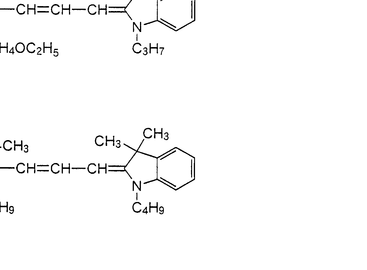
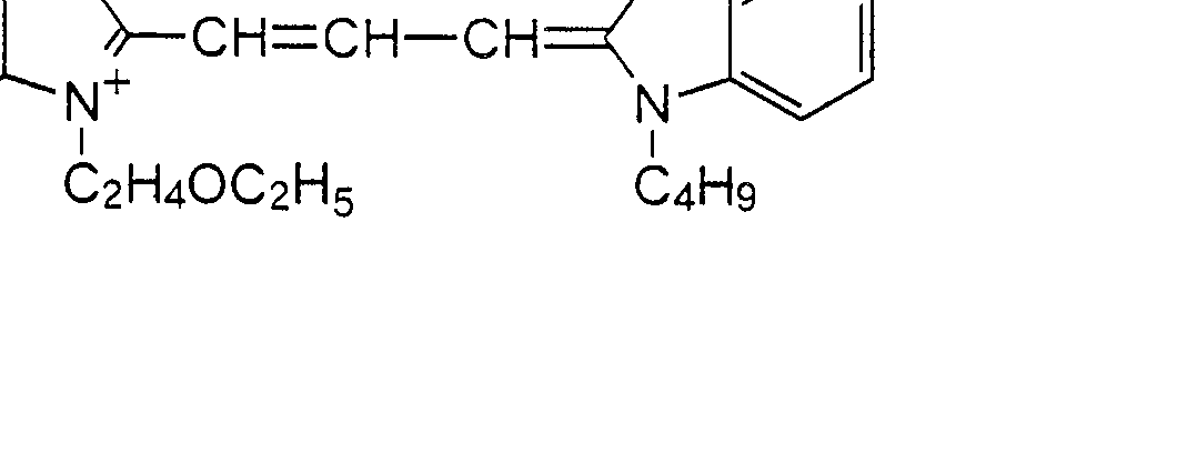


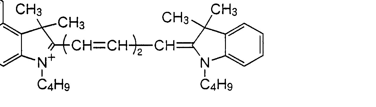


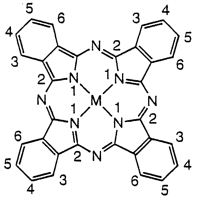


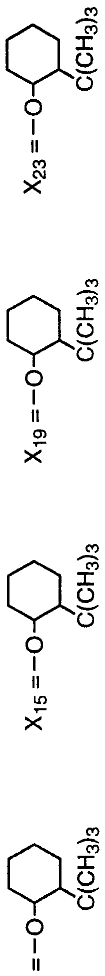


Claims


Priority Applications (6)
| Application Number | Priority Date | Filing Date | Title |
|---|---|---|---|
| KR1019980706702A KR100295371B1 (ko) | 1996-12-27 | 1997-12-22 | 광기록매체 |
| EP97949192A EP0887202B1 (en) | 1996-12-27 | 1997-12-22 | Optical recording medium |
| DE69728971T DE69728971T2 (de) | 1996-12-27 | 1997-12-22 | Optisches aufzeichnungsmedium |
| US09/117,621 US6168843B1 (en) | 1996-12-27 | 1997-12-22 | Optical recording medium |
| CA002247338A CA2247338C (en) | 1996-12-27 | 1997-12-22 | Optical recording medium |
| JP52981998A JP3364231B2 (ja) | 1996-12-27 | 1997-12-22 | 光記録媒体 |
Applications Claiming Priority (4)
| Application Number | Priority Date | Filing Date | Title |
|---|---|---|---|
| JP8/357891 | 1996-12-27 | ||
| JP35789196 | 1996-12-27 | ||
| JP9673597 | 1997-03-31 | ||
| JP9/96735 | 1997-03-31 |
Publications (1)
| Publication Number | Publication Date |
|---|---|
| WO1998029257A1 true WO1998029257A1 (fr) | 1998-07-09 |
Family
ID=26437917
Family Applications (1)
| Application Number | Title | Priority Date | Filing Date |
|---|---|---|---|
| PCT/JP1997/004735 Ceased WO1998029257A1 (fr) | 1996-12-27 | 1997-12-22 | Support d'enregistrement optique |
Country Status (8)
| Country | Link |
|---|---|
| US (1) | US6168843B1 (ja) |
| EP (1) | EP0887202B1 (ja) |
| JP (1) | JP3364231B2 (ja) |
| KR (1) | KR100295371B1 (ja) |
| CA (1) | CA2247338C (ja) |
| DE (1) | DE69728971T2 (ja) |
| TW (1) | TW359644B (ja) |
| WO (1) | WO1998029257A1 (ja) |
Cited By (24)
| Publication number | Priority date | Publication date | Assignee | Title |
|---|---|---|---|---|
| JP2000043420A (ja) * | 1998-08-03 | 2000-02-15 | Ricoh Co Ltd | 光記録媒体 |
| JP2000198273A (ja) * | 1998-11-05 | 2000-07-18 | Tdk Corp | 光記録媒体 |
| US6242067B1 (en) | 1998-10-19 | 2001-06-05 | Tdk Corporation | Optical recording medium |
| WO2004086375A1 (ja) | 2003-03-24 | 2004-10-07 | Ricoh Company Ltd. | 光記録媒体、並びに、記録再生方法及び記録再生装置 |
| US6936323B2 (en) | 2003-04-30 | 2005-08-30 | Ricoh Company, Ltd. | Optical recording medium, and method and device using the same |
| WO2005083011A1 (ja) * | 2004-02-27 | 2005-09-09 | Kabushiki Kaisha Hayashibara Seibutsu Kagaku Kenkyujo | シアニン色素 |
| WO2005092988A1 (ja) * | 2004-03-26 | 2005-10-06 | Kabushiki Kaisha Hayashibara Seibutsu Kagaku Kenkyujo | シアニン色素 |
| WO2006109618A1 (ja) | 2005-04-05 | 2006-10-19 | Adeka Corporation | シアニン化合物、光学フィルター及び光学記録材料 |
| WO2006123786A1 (ja) * | 2005-05-20 | 2006-11-23 | Kabushiki Kaisha Hayashibara Seibutsu Kagaku Kenkyujo | シアニン色素および光学記録媒体 |
| WO2007105416A1 (ja) | 2006-03-14 | 2007-09-20 | Adeka Corporation | 光学記録媒体 |
| WO2007114073A1 (ja) | 2006-03-31 | 2007-10-11 | Adeka Corporation | シアニン化合物及び光学記録材料 |
| WO2007114074A1 (ja) | 2006-03-31 | 2007-10-11 | Adeka Corporation | インドリウム化合物及び光学記録材料 |
| WO2007125892A1 (ja) | 2006-04-28 | 2007-11-08 | Adeka Corporation | 光学記録材料、カルコン型化合物及び金属錯体 |
| WO2007129503A1 (ja) | 2006-05-08 | 2007-11-15 | Adeka Corporation | 新規化合物、該化合物を用いた光学フィルター及び光学記録材料 |
| WO2007135924A1 (ja) | 2006-05-23 | 2007-11-29 | Adeka Corporation | 光学記録材料及びシアニン化合物 |
| WO2008010433A1 (fr) | 2006-07-21 | 2008-01-24 | Adeka Corporation | Composés de cyanine pontés et matières d'enregistrement optique contenant ceux-ci |
| WO2008044534A1 (en) | 2006-10-10 | 2008-04-17 | Adeka Corporation | Optical recording material |
| WO2008123404A1 (ja) | 2007-03-30 | 2008-10-16 | Adeka Corporation | シアニン化合物、該化合物を用いた光学フィルター及び光学記録材料 |
| WO2009050999A1 (ja) | 2007-10-15 | 2009-04-23 | Adeka Corporation | インドリウム化合物及び該化合物を用いた光学記録材料 |
| WO2010073857A1 (ja) | 2008-12-25 | 2010-07-01 | 株式会社Adeka | シアニン化合物を用いた近赤外線吸収材料及びシアニン化合物 |
| JP4666869B2 (ja) * | 2000-02-23 | 2011-04-06 | 株式会社林原生物化学研究所 | シアニン色素 |
| WO2012111400A1 (ja) | 2011-02-18 | 2012-08-23 | 株式会社Adeka | 着色感光性組成物 |
| WO2012124365A1 (ja) | 2011-03-16 | 2012-09-20 | 株式会社Adeka | 光拡散性樹脂組成物及びこれを用いた光拡散シート |
| JP2018526320A (ja) * | 2015-09-10 | 2018-09-13 | ザ ヘンリー エム.ジャクソン ファウンデーション フォー ザ アドバンスメント オブ ミリタリー メディスン,インコーポレーテッド | Erg癌遺伝子阻害剤としてのアゾフェノール |
Families Citing this family (30)
| Publication number | Priority date | Publication date | Assignee | Title |
|---|---|---|---|---|
| JP3847002B2 (ja) * | 1998-05-19 | 2006-11-15 | 富士写真フイルム株式会社 | 情報記録媒体およびオキソノール化合物 |
| EP1178083A4 (en) * | 1999-12-17 | 2002-05-29 | Hayashibara Biochem Lab | Cyanine dye |
| TW572969B (en) * | 2000-02-10 | 2004-01-21 | Hayashibara Biochem Lab | Trimethine cyanine dye, light absorbent, light-resistant improver and optical recording medium containing same, and process for producing same |
| EP1130585B1 (en) * | 2000-02-28 | 2011-12-21 | FUJIFILM Corporation | Recording medium and information recording and reproducing method using the same |
| US6558768B2 (en) * | 2000-03-07 | 2003-05-06 | Ricoh Company, Ltd. | Optical recording medium and optical recording and reading method using the same |
| TW556155B (en) * | 2000-04-03 | 2003-10-01 | Sony Corp | Optical record medium |
| EP1275517B1 (en) * | 2000-04-17 | 2004-10-27 | Mitsubishi Chemical Corporation | Optical recording medium |
| TWI256634B (en) * | 2001-03-28 | 2006-06-11 | Bayer Ag | An optical data storage medium containing a diaza hemicyanine dye as the light-absorbing compound in the information layer |
| EP1386317A1 (de) | 2001-03-28 | 2004-02-04 | Bayer Chemicals AG | Optischer datenträger enthaltend in der informationsschicht einen cyaninfarbstoff als lichtabsorbierende verbindung |
| JP2003276342A (ja) * | 2002-03-26 | 2003-09-30 | Tdk Corp | 光記録媒体 |
| JP2004082406A (ja) * | 2002-08-23 | 2004-03-18 | Tdk Corp | 光記録媒体 |
| JP4230454B2 (ja) * | 2002-08-29 | 2009-02-25 | コーニンクレッカ フィリップス エレクトロニクス エヌ ヴィ | マルチスタック光学データ記憶媒体及びかかる媒体の使用方法 |
| EP1606810A2 (en) * | 2003-03-18 | 2005-12-21 | Koninklijke Philips Electronics N.V. | Optical information carrier comprising thermochromic or photochromic material |
| EP1611575A2 (en) * | 2003-04-04 | 2006-01-04 | Ciba SC Holding AG | High-capacity optical storage media |
| WO2004097821A1 (de) * | 2003-05-02 | 2004-11-11 | Interaxia Ag | Aufzeichnungsmedium für optischen datenspeicher, insbesondere für dvd±r |
| TWI242209B (en) * | 2003-05-09 | 2005-10-21 | Gigastorage Corp | Materials for high density optical recording media |
| US7859983B2 (en) * | 2003-07-15 | 2010-12-28 | Sharp Kabushiki Kaisha | Optical disk and optical disk recording and reproducing device |
| US20070184386A1 (en) * | 2004-02-26 | 2007-08-09 | Mitsubishi Chemical Corporation | Optical recording material and optical recording medium |
| US7208401B2 (en) * | 2004-03-12 | 2007-04-24 | Hewlett-Packard Development Company, L.P. | Method for forming a thin film |
| JP4150354B2 (ja) * | 2004-04-20 | 2008-09-17 | Tdk株式会社 | 光記録材料、光記録媒体及びその製造方法 |
| WO2005104117A1 (ja) * | 2004-04-23 | 2005-11-03 | Mitsubishi Kagaku Media Co., Ltd. | 光記録媒体 |
| PL1621584T3 (pl) * | 2004-07-29 | 2007-06-29 | Clariant Finance Bvi Ltd | Ligandy azowe na bazie aminoantypiryny i ich kompleksy z metalami do stosowania w optycznych nośnikach rejestrujących |
| JP2008510052A (ja) * | 2004-08-16 | 2008-04-03 | チバ スペシャルティ ケミカルズ ホールディング インコーポレーテッド | 大容量光学記憶媒体 |
| WO2006082229A2 (en) * | 2005-02-04 | 2006-08-10 | Clariant International Ltd | Cationic antipyrine based azo metal complex dyes for use in optical layers for optical data recording |
| JP2007056114A (ja) * | 2005-08-23 | 2007-03-08 | Tdk Corp | 色素材料、並びに、これを用いた光記録媒体及びその製造方法 |
| KR100705927B1 (ko) * | 2005-10-26 | 2007-04-12 | 제일모직주식회사 | 근적외선 흡수 및 색보정 점착제 조성물 및 이를 이용한필름 |
| JP5913776B2 (ja) | 2008-05-27 | 2016-04-27 | 株式会社Adeka | 色補正材料、フィルム形成用組成物及び光学フィルター |
| TWI376481B (en) | 2009-10-13 | 2012-11-11 | Sunonwealth Electr Mach Ind Co | Lamp |
| US8517574B2 (en) | 2010-04-30 | 2013-08-27 | Sunonwealth Electric Machine Industry Co., Ltd. | Lamp with air channel |
| WO2023014703A1 (en) * | 2021-08-04 | 2023-02-09 | Videojet Technologies Inc. | Metal complex dyes for inkjet printing |
Citations (9)
| Publication number | Priority date | Publication date | Assignee | Title |
|---|---|---|---|---|
| JPH04361088A (ja) * | 1991-06-10 | 1992-12-14 | Mitsubishi Kasei Corp | 光記録媒体 |
| US5330542A (en) * | 1990-05-25 | 1994-07-19 | Mitsubishi Kasei Corporation | Dye-incorporated composition |
| JPH0744904A (ja) * | 1993-07-30 | 1995-02-14 | Mitsubishi Chem Corp | 光記録媒体の製造方法 |
| JPH08156408A (ja) * | 1994-11-29 | 1996-06-18 | Mitsui Toatsu Chem Inc | 光記録媒体 |
| JPH08332772A (ja) * | 1995-06-06 | 1996-12-17 | Mitsubishi Chem Corp | 光記録媒体 |
| JPH0940659A (ja) * | 1995-08-01 | 1997-02-10 | Mitsui Toatsu Chem Inc | 光記録媒体 |
| JPH09193545A (ja) * | 1996-01-18 | 1997-07-29 | Mitsubishi Chem Corp | 光学記録媒体及び情報記録方法 |
| JPH09323478A (ja) * | 1996-06-06 | 1997-12-16 | Tdk Corp | 光記録媒体 |
| JPH106650A (ja) * | 1996-06-21 | 1998-01-13 | Ricoh Co Ltd | 光記録媒体 |
Family Cites Families (6)
| Publication number | Priority date | Publication date | Assignee | Title |
|---|---|---|---|---|
| JPH0737580B2 (ja) | 1986-09-24 | 1995-04-26 | 三菱化学株式会社 | クロム含金アゾ系化合物及び同化合物を含む光学記録媒体 |
| JPH0255189A (ja) | 1988-08-18 | 1990-02-23 | Matsushita Electric Ind Co Ltd | 光記録媒体 |
| JPH0351182A (ja) | 1989-07-19 | 1991-03-05 | Matsushita Electric Ind Co Ltd | 光記録媒体 |
| JPH0524360A (ja) | 1991-07-19 | 1993-02-02 | Victor Co Of Japan Ltd | 光記録媒体 |
| US5633106A (en) * | 1994-04-08 | 1997-05-27 | Mitsui Toatsu Chemicals, Inc. | Optical recording media and a method of recording and reproducing information |
| JP3273404B2 (ja) | 1995-10-24 | 2002-04-08 | 新日本製鐵株式会社 | 厚手高硬度高靱性耐摩耗鋼の製造方法 |
-
1997
- 1997-12-22 KR KR1019980706702A patent/KR100295371B1/ko not_active Expired - Fee Related
- 1997-12-22 DE DE69728971T patent/DE69728971T2/de not_active Expired - Fee Related
- 1997-12-22 WO PCT/JP1997/004735 patent/WO1998029257A1/ja not_active Ceased
- 1997-12-22 US US09/117,621 patent/US6168843B1/en not_active Expired - Fee Related
- 1997-12-22 JP JP52981998A patent/JP3364231B2/ja not_active Expired - Lifetime
- 1997-12-22 CA CA002247338A patent/CA2247338C/en not_active Expired - Fee Related
- 1997-12-22 EP EP97949192A patent/EP0887202B1/en not_active Expired - Lifetime
- 1997-12-23 TW TW086119601A patent/TW359644B/zh not_active IP Right Cessation
Patent Citations (9)
| Publication number | Priority date | Publication date | Assignee | Title |
|---|---|---|---|---|
| US5330542A (en) * | 1990-05-25 | 1994-07-19 | Mitsubishi Kasei Corporation | Dye-incorporated composition |
| JPH04361088A (ja) * | 1991-06-10 | 1992-12-14 | Mitsubishi Kasei Corp | 光記録媒体 |
| JPH0744904A (ja) * | 1993-07-30 | 1995-02-14 | Mitsubishi Chem Corp | 光記録媒体の製造方法 |
| JPH08156408A (ja) * | 1994-11-29 | 1996-06-18 | Mitsui Toatsu Chem Inc | 光記録媒体 |
| JPH08332772A (ja) * | 1995-06-06 | 1996-12-17 | Mitsubishi Chem Corp | 光記録媒体 |
| JPH0940659A (ja) * | 1995-08-01 | 1997-02-10 | Mitsui Toatsu Chem Inc | 光記録媒体 |
| JPH09193545A (ja) * | 1996-01-18 | 1997-07-29 | Mitsubishi Chem Corp | 光学記録媒体及び情報記録方法 |
| JPH09323478A (ja) * | 1996-06-06 | 1997-12-16 | Tdk Corp | 光記録媒体 |
| JPH106650A (ja) * | 1996-06-21 | 1998-01-13 | Ricoh Co Ltd | 光記録媒体 |
Non-Patent Citations (2)
| Title |
|---|
| See also references of EP0887202A4 * |
| TAKAO YOTSUYANAGI et al., "Annual Report, the Asahi Glass Foundation for the Contribution to Industrial Technology", Vol. 39, 1981, p. 273-277. * |
Cited By (32)
| Publication number | Priority date | Publication date | Assignee | Title |
|---|---|---|---|---|
| JP2000043420A (ja) * | 1998-08-03 | 2000-02-15 | Ricoh Co Ltd | 光記録媒体 |
| US6242067B1 (en) | 1998-10-19 | 2001-06-05 | Tdk Corporation | Optical recording medium |
| JP2000198273A (ja) * | 1998-11-05 | 2000-07-18 | Tdk Corp | 光記録媒体 |
| JP4666869B2 (ja) * | 2000-02-23 | 2011-04-06 | 株式会社林原生物化学研究所 | シアニン色素 |
| WO2004086375A1 (ja) | 2003-03-24 | 2004-10-07 | Ricoh Company Ltd. | 光記録媒体、並びに、記録再生方法及び記録再生装置 |
| US7532556B2 (en) | 2003-03-24 | 2009-05-12 | Ricoh Company, Ltd. | Optical recording medium, recording and reproducing method, and recording and reproducing apparatus using heating pulses which are high-output at leading and trailing ends |
| US6936323B2 (en) | 2003-04-30 | 2005-08-30 | Ricoh Company, Ltd. | Optical recording medium, and method and device using the same |
| US8350015B2 (en) | 2004-02-27 | 2013-01-08 | Kabushiki Kaisha Hayashibara Seibutsu Kagaku Kenkyujo | Cyanine dye |
| JP4724113B2 (ja) * | 2004-02-27 | 2011-07-13 | 株式会社林原生物化学研究所 | シアニン色素 |
| WO2005083011A1 (ja) * | 2004-02-27 | 2005-09-09 | Kabushiki Kaisha Hayashibara Seibutsu Kagaku Kenkyujo | シアニン色素 |
| WO2005092988A1 (ja) * | 2004-03-26 | 2005-10-06 | Kabushiki Kaisha Hayashibara Seibutsu Kagaku Kenkyujo | シアニン色素 |
| WO2006109618A1 (ja) | 2005-04-05 | 2006-10-19 | Adeka Corporation | シアニン化合物、光学フィルター及び光学記録材料 |
| WO2006123786A1 (ja) * | 2005-05-20 | 2006-11-23 | Kabushiki Kaisha Hayashibara Seibutsu Kagaku Kenkyujo | シアニン色素および光学記録媒体 |
| CN101193985A (zh) * | 2005-05-20 | 2008-06-04 | 三菱化学媒体股份有限公司 | 花青染料以及光学记录介质 |
| EP2360023A1 (en) | 2006-03-14 | 2011-08-24 | Adeka Corporation | Optical recording medium |
| WO2007105416A1 (ja) | 2006-03-14 | 2007-09-20 | Adeka Corporation | 光学記録媒体 |
| EP2360694A1 (en) | 2006-03-14 | 2011-08-24 | Adeka Corporation | Optical recording medium |
| EP2371905A1 (en) | 2006-03-31 | 2011-10-05 | Adeka Corporation | Cyanine compound and optical recording material |
| WO2007114074A1 (ja) | 2006-03-31 | 2007-10-11 | Adeka Corporation | インドリウム化合物及び光学記録材料 |
| WO2007114073A1 (ja) | 2006-03-31 | 2007-10-11 | Adeka Corporation | シアニン化合物及び光学記録材料 |
| WO2007125892A1 (ja) | 2006-04-28 | 2007-11-08 | Adeka Corporation | 光学記録材料、カルコン型化合物及び金属錯体 |
| WO2007129503A1 (ja) | 2006-05-08 | 2007-11-15 | Adeka Corporation | 新規化合物、該化合物を用いた光学フィルター及び光学記録材料 |
| WO2007135924A1 (ja) | 2006-05-23 | 2007-11-29 | Adeka Corporation | 光学記録材料及びシアニン化合物 |
| WO2008010433A1 (fr) | 2006-07-21 | 2008-01-24 | Adeka Corporation | Composés de cyanine pontés et matières d'enregistrement optique contenant ceux-ci |
| WO2008044534A1 (en) | 2006-10-10 | 2008-04-17 | Adeka Corporation | Optical recording material |
| WO2008123404A1 (ja) | 2007-03-30 | 2008-10-16 | Adeka Corporation | シアニン化合物、該化合物を用いた光学フィルター及び光学記録材料 |
| WO2009050999A1 (ja) | 2007-10-15 | 2009-04-23 | Adeka Corporation | インドリウム化合物及び該化合物を用いた光学記録材料 |
| WO2010073857A1 (ja) | 2008-12-25 | 2010-07-01 | 株式会社Adeka | シアニン化合物を用いた近赤外線吸収材料及びシアニン化合物 |
| WO2012111400A1 (ja) | 2011-02-18 | 2012-08-23 | 株式会社Adeka | 着色感光性組成物 |
| WO2012124365A1 (ja) | 2011-03-16 | 2012-09-20 | 株式会社Adeka | 光拡散性樹脂組成物及びこれを用いた光拡散シート |
| JP2018526320A (ja) * | 2015-09-10 | 2018-09-13 | ザ ヘンリー エム.ジャクソン ファウンデーション フォー ザ アドバンスメント オブ ミリタリー メディスン,インコーポレーテッド | Erg癌遺伝子阻害剤としてのアゾフェノール |
| US11648239B2 (en) | 2015-09-10 | 2023-05-16 | The Henry M. Jackson Foundation For The Advancement Of Military Medicine, Inc. | Azophenols as ERG oncogene inhibitors |
Also Published As
| Publication number | Publication date |
|---|---|
| JP3364231B2 (ja) | 2003-01-08 |
| DE69728971T2 (de) | 2005-04-07 |
| CA2247338C (en) | 2001-01-30 |
| DE69728971D1 (de) | 2004-06-09 |
| EP0887202A4 (en) | 2000-04-19 |
| US6168843B1 (en) | 2001-01-02 |
| KR19990087296A (ko) | 1999-12-27 |
| TW359644B (en) | 1999-06-01 |
| EP0887202B1 (en) | 2004-05-06 |
| CA2247338A1 (en) | 1998-07-09 |
| EP0887202A1 (en) | 1998-12-30 |
| KR100295371B1 (ko) | 2001-11-26 |
Similar Documents
| Publication | Publication Date | Title |
|---|---|---|
| WO1998029257A1 (fr) | Support d'enregistrement optique | |
| JPWO1998029257A1 (ja) | 光記録媒体 | |
| JP2791944B2 (ja) | ホルマザン金属錯体系色素を用いた光記録媒体および光安定化方法 | |
| KR100905689B1 (ko) | 광학 기록 매체, 금속 착체 화합물 및 유기 색소 화합물 | |
| WO2008138812A2 (en) | Pyridinone based azo dyes and their metal complex salts | |
| JPH09323478A (ja) | 光記録媒体 | |
| JP3724531B2 (ja) | 光記録媒体 | |
| JP3441410B2 (ja) | 光記録媒体 | |
| CN101238182B (zh) | 光学记录介质、光记录材料及金属络合物 | |
| JPH07266705A (ja) | 光記録ディスク | |
| JP3328169B2 (ja) | 金属錯体系色素を用いた光記録媒体 | |
| JP4519795B2 (ja) | 光学記録媒体及び金属錯体化合物 | |
| JP4523366B2 (ja) | アゾ金属キレート色素及び光学記録媒体 | |
| JP3411771B2 (ja) | 光記録媒体 | |
| US20070184386A1 (en) | Optical recording material and optical recording medium | |
| JP2005271587A (ja) | 光記録材料及び光学記録媒体 | |
| JP3972544B2 (ja) | 金属キレート色素及び該金属キレート色素を使用する光学記録媒体 | |
| WO2007048709A1 (en) | Anionic barbituric acid based azomethine metal complex dyes and their use in optical layers for optical data recording | |
| JPWO1991018057A1 (ja) | 金属キレート化合物およびそれを用いた光学的記録媒体 | |
| JPH0751673B2 (ja) | 金属キレート化合物およびそれを用いた光学的記録媒体 | |
| JPH0999642A (ja) | 光記録媒体 | |
| AU2006210275A1 (en) | Cationic antipyrine based azo metal complex dyes for use in optical layers for optical data recording | |
| MXPA98006926A (en) | Optical recording medium | |
| JP2001080211A (ja) | アゾ金属錯体系色素および光記録媒体 | |
| JPH07287862A (ja) | アゾ色素を用いる光学的情報記録素子 |
Legal Events
| Date | Code | Title | Description |
|---|---|---|---|
| AK | Designated states |
Kind code of ref document: A1 Designated state(s): CA JP KR MX US |
|
| AL | Designated countries for regional patents |
Kind code of ref document: A1 Designated state(s): AT BE CH DE DK ES FI FR GB GR IE IT LU MC NL PT SE |
|
| WWE | Wipo information: entry into national phase |
Ref document number: 1997949192 Country of ref document: EP |
|
| ENP | Entry into the national phase |
Ref document number: 2247338 Country of ref document: CA Ref country code: CA Ref document number: 2247338 Kind code of ref document: A Format of ref document f/p: F |
|
| WWE | Wipo information: entry into national phase |
Ref document number: PA/a/1998/006926 Country of ref document: MX |
|
| WWE | Wipo information: entry into national phase |
Ref document number: 1019980706702 Country of ref document: KR |
|
| 121 | Ep: the epo has been informed by wipo that ep was designated in this application | ||
| WWP | Wipo information: published in national office |
Ref document number: 1997949192 Country of ref document: EP |
|
| WWE | Wipo information: entry into national phase |
Ref document number: 09117621 Country of ref document: US |
|
| WWP | Wipo information: published in national office |
Ref document number: 1019980706702 Country of ref document: KR |
|
| WWG | Wipo information: grant in national office |
Ref document number: 1019980706702 Country of ref document: KR |
|
| WWG | Wipo information: grant in national office |
Ref document number: 1997949192 Country of ref document: EP |