WO2010001732A1 - 固定床多管式反応器への固体粒状物の充填方法 - Google Patents
固定床多管式反応器への固体粒状物の充填方法 Download PDFInfo
- Publication number
- WO2010001732A1 WO2010001732A1 PCT/JP2009/061096 JP2009061096W WO2010001732A1 WO 2010001732 A1 WO2010001732 A1 WO 2010001732A1 JP 2009061096 W JP2009061096 W JP 2009061096W WO 2010001732 A1 WO2010001732 A1 WO 2010001732A1
- Authority
- WO
- WIPO (PCT)
- Prior art keywords
- reaction tube
- catalyst
- solid particulate
- filling
- particulate matter
- Prior art date
- Legal status (The legal status is an assumption and is not a legal conclusion. Google has not performed a legal analysis and makes no representation as to the accuracy of the status listed.)
- Ceased
Links
Images

Classifications
-
- C—CHEMISTRY; METALLURGY
- C07—ORGANIC CHEMISTRY
- C07C—ACYCLIC OR CARBOCYCLIC COMPOUNDS
- C07C51/00—Preparation of carboxylic acids or their salts, halides or anhydrides
-
- B—PERFORMING OPERATIONS; TRANSPORTING
- B01—PHYSICAL OR CHEMICAL PROCESSES OR APPARATUS IN GENERAL
- B01J—CHEMICAL OR PHYSICAL PROCESSES, e.g. CATALYSIS OR COLLOID CHEMISTRY; THEIR RELEVANT APPARATUS
- B01J23/00—Catalysts comprising metals or metal oxides or hydroxides, not provided for in group B01J21/00
- B01J23/002—Mixed oxides other than spinels, e.g. perovskite
-
- B—PERFORMING OPERATIONS; TRANSPORTING
- B01—PHYSICAL OR CHEMICAL PROCESSES OR APPARATUS IN GENERAL
- B01J—CHEMICAL OR PHYSICAL PROCESSES, e.g. CATALYSIS OR COLLOID CHEMISTRY; THEIR RELEVANT APPARATUS
- B01J23/00—Catalysts comprising metals or metal oxides or hydroxides, not provided for in group B01J21/00
- B01J23/70—Catalysts comprising metals or metal oxides or hydroxides, not provided for in group B01J21/00 of the iron group metals or copper
- B01J23/76—Catalysts comprising metals or metal oxides or hydroxides, not provided for in group B01J21/00 of the iron group metals or copper combined with metals, oxides or hydroxides provided for in groups B01J23/02 - B01J23/36
- B01J23/84—Catalysts comprising metals or metal oxides or hydroxides, not provided for in group B01J21/00 of the iron group metals or copper combined with metals, oxides or hydroxides provided for in groups B01J23/02 - B01J23/36 with arsenic, antimony, bismuth, vanadium, niobium, tantalum, polonium, chromium, molybdenum, tungsten, manganese, technetium or rhenium
- B01J23/85—Chromium, molybdenum or tungsten
- B01J23/888—Tungsten
- B01J23/8885—Tungsten containing also molybdenum
-
- B—PERFORMING OPERATIONS; TRANSPORTING
- B01—PHYSICAL OR CHEMICAL PROCESSES OR APPARATUS IN GENERAL
- B01J—CHEMICAL OR PHYSICAL PROCESSES, e.g. CATALYSIS OR COLLOID CHEMISTRY; THEIR RELEVANT APPARATUS
- B01J35/00—Catalysts, in general, characterised by their form or physical properties
- B01J35/19—Catalysts containing parts with different compositions
-
- B—PERFORMING OPERATIONS; TRANSPORTING
- B01—PHYSICAL OR CHEMICAL PROCESSES OR APPARATUS IN GENERAL
- B01J—CHEMICAL OR PHYSICAL PROCESSES, e.g. CATALYSIS OR COLLOID CHEMISTRY; THEIR RELEVANT APPARATUS
- B01J8/00—Chemical or physical processes in general, conducted in the presence of fluids and solid particles; Apparatus for such processes
- B01J8/008—Details of the reactor or of the particulate material; Processes to increase or to retard the rate of reaction
-
- B—PERFORMING OPERATIONS; TRANSPORTING
- B01—PHYSICAL OR CHEMICAL PROCESSES OR APPARATUS IN GENERAL
- B01J—CHEMICAL OR PHYSICAL PROCESSES, e.g. CATALYSIS OR COLLOID CHEMISTRY; THEIR RELEVANT APPARATUS
- B01J8/00—Chemical or physical processes in general, conducted in the presence of fluids and solid particles; Apparatus for such processes
- B01J8/02—Chemical or physical processes in general, conducted in the presence of fluids and solid particles; Apparatus for such processes with stationary particles, e.g. in fixed beds
- B01J8/0292—Chemical or physical processes in general, conducted in the presence of fluids and solid particles; Apparatus for such processes with stationary particles, e.g. in fixed beds with stationary packing material in the bed, e.g. bricks, wire rings, baffles
-
- B—PERFORMING OPERATIONS; TRANSPORTING
- B01—PHYSICAL OR CHEMICAL PROCESSES OR APPARATUS IN GENERAL
- B01J—CHEMICAL OR PHYSICAL PROCESSES, e.g. CATALYSIS OR COLLOID CHEMISTRY; THEIR RELEVANT APPARATUS
- B01J8/00—Chemical or physical processes in general, conducted in the presence of fluids and solid particles; Apparatus for such processes
- B01J8/02—Chemical or physical processes in general, conducted in the presence of fluids and solid particles; Apparatus for such processes with stationary particles, e.g. in fixed beds
- B01J8/06—Chemical or physical processes in general, conducted in the presence of fluids and solid particles; Apparatus for such processes with stationary particles, e.g. in fixed beds in tube reactors; the solid particles being arranged in tubes
- B01J8/067—Heating or cooling the reactor
-
- C—CHEMISTRY; METALLURGY
- C07—ORGANIC CHEMISTRY
- C07C—ACYCLIC OR CARBOCYCLIC COMPOUNDS
- C07C51/00—Preparation of carboxylic acids or their salts, halides or anhydrides
- C07C51/16—Preparation of carboxylic acids or their salts, halides or anhydrides by oxidation
- C07C51/21—Preparation of carboxylic acids or their salts, halides or anhydrides by oxidation with molecular oxygen
- C07C51/25—Preparation of carboxylic acids or their salts, halides or anhydrides by oxidation with molecular oxygen of unsaturated compounds containing no six-membered aromatic ring
- C07C51/252—Preparation of carboxylic acids or their salts, halides or anhydrides by oxidation with molecular oxygen of unsaturated compounds containing no six-membered aromatic ring of propene, butenes, acrolein or methacrolein
-
- B—PERFORMING OPERATIONS; TRANSPORTING
- B01—PHYSICAL OR CHEMICAL PROCESSES OR APPARATUS IN GENERAL
- B01J—CHEMICAL OR PHYSICAL PROCESSES, e.g. CATALYSIS OR COLLOID CHEMISTRY; THEIR RELEVANT APPARATUS
- B01J2208/00—Processes carried out in the presence of solid particles; Reactors therefor
- B01J2208/00743—Feeding or discharging of solids
- B01J2208/00752—Feeding
-
- B—PERFORMING OPERATIONS; TRANSPORTING
- B01—PHYSICAL OR CHEMICAL PROCESSES OR APPARATUS IN GENERAL
- B01J—CHEMICAL OR PHYSICAL PROCESSES, e.g. CATALYSIS OR COLLOID CHEMISTRY; THEIR RELEVANT APPARATUS
- B01J2208/00—Processes carried out in the presence of solid particles; Reactors therefor
- B01J2208/02—Processes carried out in the presence of solid particles; Reactors therefor with stationary particles
- B01J2208/023—Details
- B01J2208/024—Particulate material
- B01J2208/025—Two or more types of catalyst
-
- B—PERFORMING OPERATIONS; TRANSPORTING
- B01—PHYSICAL OR CHEMICAL PROCESSES OR APPARATUS IN GENERAL
- B01J—CHEMICAL OR PHYSICAL PROCESSES, e.g. CATALYSIS OR COLLOID CHEMISTRY; THEIR RELEVANT APPARATUS
- B01J2523/00—Constitutive chemical elements of heterogeneous catalysts
-
- B—PERFORMING OPERATIONS; TRANSPORTING
- B01—PHYSICAL OR CHEMICAL PROCESSES OR APPARATUS IN GENERAL
- B01J—CHEMICAL OR PHYSICAL PROCESSES, e.g. CATALYSIS OR COLLOID CHEMISTRY; THEIR RELEVANT APPARATUS
- B01J35/00—Catalysts, in general, characterised by their form or physical properties
- B01J35/40—Catalysts, in general, characterised by their form or physical properties characterised by dimensions, e.g. grain size
-
- B—PERFORMING OPERATIONS; TRANSPORTING
- B01—PHYSICAL OR CHEMICAL PROCESSES OR APPARATUS IN GENERAL
- B01J—CHEMICAL OR PHYSICAL PROCESSES, e.g. CATALYSIS OR COLLOID CHEMISTRY; THEIR RELEVANT APPARATUS
- B01J37/00—Processes, in general, for preparing catalysts; Processes, in general, for activation of catalysts
- B01J37/0009—Use of binding agents; Moulding; Pressing; Powdering; Granulating; Addition of materials ameliorating the mechanical properties of the product catalyst
Definitions
- the present invention relates to a method of filling a fixed-bed multitubular reactor with solid particulate matter such as a catalyst.
- a method for filling a fixed bed multitubular reactor with a solid particulate material such as a catalyst a method of dropping the solid particulate material from the upper end opening of each reaction tube and filling it is common.
- a part of the solid particulates collapses or pulverizes due to physical impact at the time of dropping, and the resulting particulate matter increases pressure loss and substantially reduces the amount of catalyst involved in the reaction. May be incurred.
- it may cause the yield of the target product and the catalyst life to decrease.
- the reaction tube may be blocked by a by-product generated due to a heterogeneous reaction in the reactor.
- Patent Document 1 discloses a method in which a catalyst is dropped and filled by interposing a string-like substance having a shape and a thickness that does not prevent the catalyst from falling in the reactor.
- Patent Document 3 when a multi-tubular reactor is filled with a pellet-shaped catalyst, air is raised from the bottom of the reaction tube to about 1/2 to 2 times the minimum fluidization speed, A more dropping method is disclosed.
- Patent Document 4 discloses a method of maintaining the moisture concentration of the atmospheric gas in the reaction tube at 0.3 to 1.2% by mass when dropping and filling the solid catalyst into the reactor.
- JP 2003-340266 A Japanese Patent Laid-Open No. 6-7669 JP 62-30545 A JP 2005-224661 A
- an object of the present invention is to effectively remove not only a small amount of generated particulates from a reaction tube when a solid particle such as a catalyst is charged into a fixed bed multitubular reactor,
- An object of the present invention is to provide a method for stably operating a multitubular reactor in the long term.
- the solid particulate filling method of the present invention that has solved the above-mentioned problems is a method for filling each reaction tube of a fixed-bed multitubular reactor with solid particulates, and two or more kinds of solid particulates. In such a manner that a gaseous fluid is introduced into the reaction tube once every time at least each solid particulate layer is filled.
- the method of the present invention it is possible to effectively remove the particulate matter generated when filling the solid particulate matter, and the pressure loss can be easily adjusted. Further, the pressure loss increases with time and the pressure loss of each reaction tube varies. Is also suppressed. As a result, when the gas phase catalytic oxidation reaction is performed using the fixed bed multitubular reactor, the target product can be obtained in a high yield stably for a long period of time.
- the present invention it is possible to easily remove the particulate matter generated at the time of filling the solid particulate matter from the reaction tube.
- the fixed bed multitubular reactor has a low pressure loss, and the pressure loss can be adjusted. It is easy and the increase in pressure loss over time and the variation in pressure loss for each reaction tube are suppressed, and the target product can be obtained in a high yield stably for a long period of time.
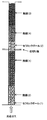
- Example 1 The schematic diagram of the filling specification of the solid granular material in Example 1 is represented.
- the schematic diagram of the filling specification of the solid granular material in Example 10 is represented.
- the solid particulate matter filling method of the present invention includes a filling step of filling solid particulate matter in the axial direction of each reactor of a fixed bed multitubular reactor; and after the filling step, A gas introduction step for introducing a fluid; the filling step and the gas introduction step are performed at least twice.
- the fixed bed multitubular reactor that can be used in the present invention is not particularly limited, but a general reaction tube having a circular cross section is used.
- the inner diameter (D) of the reaction tube is not particularly limited, but is preferably 15 to 50 mm, more preferably 20 to 40 mm, and further preferably 22 to 38 mm.
- the length of the reaction tube is determined according to the capability of the related equipment, but can be appropriately selected within the range of 1 to 10 m.
- solid particulate material used in the present invention examples include a catalyst and an inert substance.
- a catalyst is used as at least one of the solid particulates.
- the type thereof is not particularly limited as long as it is packed and used in a fixed bed multitubular reactor.
- known catalysts mentioned in (1) to (9) below Can be used.
- (1) A catalyst containing silver as an essential component and producing ethylene oxide by oxidizing ethylene in the gas phase Japanese Patent Laid-Open Nos. 63-116743, 62-4444, and 5-329368
- No., JP-A-10-510212, JP-A-5-84440, etc. Japanese Patent Laid-Open Nos. 63-116743, 62-4444, and 5-329368
- the catalyst which is an example of the solid particulate material used by filling the fixed bed multitubular reactor of the present invention is limited to the solid particulate catalyst of the above (1) to (9) used for the gas phase catalytic oxidation reaction.
- a solid particulate catalyst used in an ammoxidation reaction, a hydrogenation reaction, a dehydrogenation reaction and the like is also included.
- the catalytically active components including the above-mentioned essential components may be used as they are depending on the reaction to be used, or a molded catalyst that is partially mixed with a powdery substance that is inert to the reaction is used.
- a supported catalyst in which a catalytically active component is supported on a support inert to the reaction may be used.
- the method for preparing these catalysts may be appropriately employed depending on the reaction to be used, and can be produced by a conventionally known method such as the method described in each of the above patent publications, and is not particularly limited.
- the shape of the catalyst is not particularly limited, and for example, a catalyst having a known shape such as a columnar shape, a ring shape, a spherical shape, or an indefinite shape can be used.
- the size of the catalyst is not particularly limited as long as it can fit in the reaction tube, but the particle size (d) of the catalyst has a ratio D / d of 2/1 or more in relation to the inner diameter (D) of the reaction tube to be filled. It is preferably 2.5 / 1 or more, more preferably 15/1 or less, and even more preferably 10/1 or less.
- the particle size (d) of the catalyst is the diameter of the catalyst when it is spherical, the diameter of a circular or multi-circular cross section when it is a cylinder or ring shape, and the diameter of any other shape. It means the longest of any two points of the catalyst.
- the ratio h / ⁇ of the height (h: length in the direction perpendicular to the cross section) to the cross-sectional diameter ( ⁇ ) is 0.3 / 1 or more and 3 / A range of 1 or less is preferable.
- Such a catalyst is easy to handle and is preferable from the viewpoint of production.
- the catalyst charged in each layer of the solid particulates formed in each reaction tube of the fixed bed multitubular reactor does not need to be a single type, for example, It may be a mixture of a plurality of types of catalysts having different compositions, shapes and activities, or a mixture of a catalyst and an inert carrier.
- the inert substance means a substance that is generally inactive with respect to the raw material and target product of the gas phase catalytic oxidation reaction.
- examples of the inert substance include a support for supporting the catalyst in filling the fixed bed multi-tubular reactor; a catalyst diluent; a substance used as a preheating layer or a cooling layer for the reaction gas.
- Specific examples include silica, alumina, silica alumina, metal (such as stainless steel), and the like.
- the shape of the inert substance is not particularly limited, and examples thereof include a spherical shape, a ring shape, a Raschig ring, and a cylindrical shape. Only one inert substance may be used, or two or more inert substances may be used in appropriate combination.
- the size of the inert substance is not particularly limited as long as it fits in the reaction tube, and an inert substance having a size in the same range as the size of the catalyst described above may be used.
- a known method can be used as the working method for filling the fixed bed multi-tubular reactor with the solid particulate matter. For example, it can be carried out efficiently by using a filling machine disclosed in Japanese Utility Model Publication No. 1-333152, Japanese Patent Publication No.3-9770, Japanese Patent Application Laid-Open No. 11-333282, Japanese Patent Application Laid-Open No. 2002-306953, etc. I can do it.
- the number of layers of the solid granular material is not particularly limited, but about 2 to 5 layers are sufficient considering the removal efficiency and workability of the granular material.
- the total layer length of the solid granular material filled in the reaction tube is not particularly limited as long as it is equal to or shorter than the length of the reaction tube, and can be appropriately selected within a range equal to or shorter than the length of the reaction tube.
- the gaseous fluid for removing the particulate matter generated during the filling of the solid particulate matter into the fixed bed multitubular reactor has substantially no influence on the solid particulate matter to be filled. If it is, it will not specifically limit, but air and nitrogen are preferable from an industrial viewpoint. Air is particularly preferable from the viewpoint of safety and economy.
- the temperature and humidity of the gaseous fluid are not particularly limited as long as they do not substantially affect the solid particles to be filled. Preferably, the temperature of the fluid is about 1 ° C. to 60 ° C. The humidity may be 90% or less.
- the flow rate of the gaseous fluid flowing in the reaction tube can be determined as appropriate according to the shape of solid particulate matter to be filled such as a catalyst and the filling specification, and particularly if it is within the range in which the granular material existing in the reaction tube is pushed out of the tube. It is not limited.
- the flow rate (linear velocity) of the gaseous fluid flowing through the reaction tube is preferably 0.8 m / s or more, and 1.1 m / s or more. Is more preferable, and 2.0 m / s or less is preferable.
- the upper limit of the gaseous fluid is preferably 2.0 m / s.
- the linear velocity of the gaseous fluid flowing through the reaction tube is calculated by dividing the volume (standard state) of the gaseous fluid introduced into the reaction tube per unit time by the reaction tube cross-sectional area.
- the time for flowing the gaseous fluid to the reaction tube can be appropriately determined depending on the shape of the solid particulate matter to be filled such as a catalyst and the filling specification, and is particularly within the range in which the particulate matter existing in the reaction tube is extruded from the inside of the tube. It is not limited. Usually, if the flow rate of the gaseous fluid to flow is fast, the flow time (processing time) is short, and if the flow rate of the gaseous fluid to flow is slow, the flow time is long. Assuming a general reactor used for the gas phase catalytic oxidation reaction, the product of the linear velocity of the gaseous fluid and the processing time is, for example, more than twice the layer length of the solid granular material filled in the reaction tube. It is preferable that Specifically, the product of the linear velocity of the gaseous fluid and the treatment time is preferably 10 m or more, and more preferably 20 m or more.
- each layer of the solid particulate matter is further finely divided and packed. It is also possible to introduce a gaseous fluid each time the part is filled, and it is included in the scope of the present invention.
- the gaseous fluid may flow from either the upper end or the lower end of the reaction tube, and can be appropriately determined depending on the structure of the fixed bed multitubular reactor and the solid particulate matter filling specifications.
- the gaseous fluid is introduced from the upper end of the reaction tube. If the gaseous fluid is introduced from the upper end of the reaction tube, it is possible to effectively extrude the powder particles out of the reaction tube in combination with the sedimentation effect due to the weight of the particles.
- the above-mentioned removal process of the particulate matter may be performed for each reaction tube, or all the reaction tubes in the fixed bed multitubular reactor may be processed at a time.
- the gaseous fluid is introduced into the reaction tube, and at the same time, the opposite side of the reaction tube into which the gaseous fluid is introduced is sucked by reducing the pressure, etc. It can remove objects. At that time, suction may be performed for each reaction tube, or all reaction tubes in the fixed-bed multitubular reactor may be performed.
- the particulate matter discharged by the gaseous fluid from the reaction tube after filling the solid particulate matter can be collected by a general method.
- a bag filter is installed at the outlet side of the reaction tube through which the gaseous fluid flows.
- the particulate matter discharged from the reaction tube may be collected.
- the pressure loss of each reaction tube after the removal of the particulate matter is preferably 85 to 115% ( ⁇ 15% of the average value), more preferably the average value (average pressure loss). Is adjusted to be in the range of 92 to 108% ( ⁇ 8% of the average value). By setting within this range, the target product can be obtained in a high yield stably over a longer period of time.
- the average pressure loss is obtained by measuring the pressure loss for all the reaction tubes of the fixed bed multitubular reactor, and it corresponds to 5% of the total number of reaction tubes of the fixed bed multitubular reactor. It is also possible to measure the pressure loss for a certain number of reaction tubes and use the average value obtained as the average pressure loss.
- the pressure loss after filling the solid particulate matter and removing the particulate matter is such that air, nitrogen or other gas is introduced from the upper portion of the reaction tube at a constant flow rate with the lower portion of the reaction tube open. It is the value of the pressure in the upper part of the reaction tube.
- the flow rate of a gas such as air or nitrogen used for the measurement is not particularly limited, but can be appropriately determined in consideration of the flow rate per reaction tube when actually used for the reaction.
- Reference example 1 (Preparation of catalyst) While heating and stirring 1,500 parts of distilled water, 500 parts of ammonium paramolybdate was dissolved therein to obtain Liquid A. Separately, 398 parts of cobalt nitrate and 199 parts of nickel nitrate were dissolved in 500 parts of distilled water to obtain a liquid B. Separately, 137 parts of bismuth nitrate and 95 parts of ferric nitrate were dissolved in a solution made acidic by adding 25 parts of concentrated nitric acid (65%) to 100 parts of distilled water to obtain a liquid C. Liquid B and liquid C were added dropwise to liquid A, and then 3.6 parts of potassium nitrate and 126 parts of tungsten trioxide were added.
- the slurry thus obtained was heated and stirred to evaporate the solvent.
- the obtained dried product was dried at 200 ° C. and pulverized to 150 ⁇ m or less to obtain catalyst powder.
- the metal element composition excluding oxygen of the catalyst (1) was as follows.
- Catalyst (1) Mo 12 Bi 1.2 W 2.3 Fe 1.0 Co 5.8 Ni 2.9 K 0.15
- a catalyst (2) was obtained in the same manner as in Reference Example 1 except that it was extruded into a ring shape having an outer diameter of 8 mm, an inner diameter of 2.5 mm, and a length of 8 mm.
- the metal element composition of the catalyst (2) was the same as that of the catalyst (1).
- Example 1 In a fixed bed multitubular reactor comprising 13,000 reaction tubes (reaction tube diameter 25 mm, length 3,500 mm) and a shell for flowing a heat medium covering the reaction tube, the average particle diameter is measured from the bottom of the reaction tube.
- Each solid granular material was dropped from the upper part of the reaction tube and filled so that the layer lengths were 150 mm, 850 mm, and 2,200 mm in the order of 8 mm ceramic balls, catalyst (2), and catalyst (1) (FIG. 1). ).
- air at 20 ° C. is fed from the top of the reaction tube at a linear speed of 1.2 m / s per reaction tube at an introduction time of 12 seconds.
- the removal process of the granular material was performed.
- the removed particulate matter was collected by a bag filter installed at the bottom of the reaction tube.
- the average pressure loss of all the reaction tubes was measured. The measurement results are shown in Table 1.
- Example 2 In Example 1, the solid particulate matter was charged in the same manner as in Example 1 except that the introduction time of air introduced into the reaction tube for removing the particulate matter was changed to 16 seconds after the catalyst (1) was charged. went. The results are shown in Table 1.
- Example 3 In Example 2, the introduction time of the air introduced into the reaction tube for removing the particulate matter after filling of the catalyst (2) was set to 15 seconds, and the reaction tube was removed for removing the particulate matter after filling of the catalyst (1).
- the solid granular material was filled in the same manner as in Example 1 except that the linear velocity of the air to be introduced was changed to 1.5 m / s. The results are shown in Table 1.
- Example 4 In Example 3, when the catalyst filling and the particulate removal process were performed while using the exhaust suction device while suctioning from the lower part of the reaction tube, the solid particulates were the same as in Example 3. Filling was performed. The results are shown in Table 1.
- Comparative Example 1 In Example 1, the solid particulate matter was filled in exactly the same manner as in Example 1 except that the removal of the particulate matter by introducing air was not performed, and the average pressure loss at that time was measured. The results are shown in Table 1. In Comparative Example 1, since the removal of the particulates by introducing air was not performed, the average pressure loss was higher than in Examples 1 to 4.
- Reference example 3 While heating and stirring 3000 parts of distilled water, 500 parts of ammonium molybdate, 83 parts of ammonium paratungstate and 166 parts of ammonium metavanadate were dissolved therein. Separately, 200 parts of copper nitrate was dissolved in 185 parts of distilled water. The obtained two solutions were mixed, and 10 parts of antimony trioxide was further added to obtain a suspension. The obtained suspension was evaporated to dryness, and the obtained dried product was calcined at 350 ° C. for about 4 hours in an air atmosphere and then pulverized to 150 ⁇ m or less to obtain a catalyst powder.
- Reference example 4 In Reference Example 3, except that the amount of ammonium metavanadate was changed to 127 parts, 34 parts of cobalt nitrate was added together with copper nitrate, and the support was changed to a silica-alumina spherical support having an average particle size of 7.0 mm.
- a catalyst (4) was prepared in the same manner as in Reference Example 3.
- the metal element composition excluding oxygen and carrier of the catalyst (4) was as follows. Catalyst (4) Mo 12 V 4.6 W 1.3 Cu 3.5 Co 0.5 Sb 0.3
- Example 5 In the same fixed bed multitubular reactor as in Example 1, the ceramic balls having an average particle diameter of 8 mm, the catalyst (4), and the catalyst (3) in this order from the lower part of the reaction tube have layer lengths of 150 mm, 900 mm, 1, Except that each solid granular material was filled so as to be 800 mm, filling and removal of the granular material were performed in the same manner as in Example 1, and the average pressure loss of all the reaction tubes was measured. The results are shown in Table 1.
- Example 6 the linear velocity of the air introduced into the reaction tube for removing the particulate matter after filling of the catalyst (4) is 1.5 m / s, and for removing the particulate matter after filling of the catalyst (3).
- the solid particulate matter was filled in the same manner as in Example 5 except that the linear velocity of air introduced into the reaction tube was changed to 1.5 m / s and the introduction time was changed to 18 seconds. The results are shown in Table 1.
- Example 7 when performing the filling of the catalyst and the removal process of the particulate matter, the solid particulate matter was obtained in the same manner as in Example 6, except that the exhaust suction device was used while suctioning from the lower part of the reaction tube. Filling was performed. The results are shown in Table 1.
- Comparative Example 2 In Example 5, the solid particulate matter was filled in the same manner as in Example 5 except that the removal treatment of the particulate matter was not performed, and the average pressure loss at that time was measured. The results are shown in Table 1. In Comparative Example 2, since the removal of the particulates by introducing air was not performed, the average pressure loss was higher than in Examples 5-7.
- Example 8 The upper outlet of the reactor of Example 4 (referred to as “first reactor”) and the lower inlet of the reactor of Example 7 (referred to as “second reactor”) can be heated with steam from the outside. They were connected by a steel pipe having an inner diameter of 500 mm and a length of 5,000 mm. From the lower part of the first reactor, a mixed gas comprising 8.2% by volume of propylene, 15% by volume of oxygen, 13.8% by volume of water vapor and 63% by volume of an inert gas such as nitrogen is applied to the catalyst charged in the first reactor. On the other hand, it was introduced at a space velocity of 1550 h ⁇ 1 (STP), and propylene oxidation reaction was continued for 8000 hours. The results are shown in Table 2.
- STP space velocity
- Example 9 In Example 8, a partial extraction of the uppermost catalyst was performed for a reaction tube showing a value larger than 115% with respect to the average pressure loss of all the reaction tubes, and for a reaction tube showing a value smaller than 85%.
- the propylene oxidation reaction was continued for 8000 hours in exactly the same manner as in Example 8, except that the uppermost catalyst was added and treatment was performed so that the pressure loss in the reaction tube was within the range of 85 to 115%. I went there.
- the results are shown in Table 2.
- Example 9 after introducing the gaseous fluid into the reaction tube, the pressure loss in each reaction tube was measured and adjusted, thereby reducing the average pressure loss after 8000 hours from Example 8, and the propylene conversion rate and acrylic The acid yield was improved.
- Comparative Example 3 The propylene oxidation reaction was carried out for 8000 hours in the same manner as in Example 8, except that the reactor described in Comparative Example 1 was applied as the first reactor and the reactor described in Comparative Example 2 was applied as the second reactor. Continued. The results are shown in Table 2. In Comparative Example 3, the average pressure loss after 8000 hours was greatly increased, and the propylene conversion rate and the acrylic acid yield were decreased as compared with Examples 8 and 9.
- Example 10 The number of reaction tubes is about 9,500 (reaction tube diameter: 25 mm, length: 6,500 mm), and a fixed bed multitubular reactor composed of a shell for flowing a heat medium covering the average, in order from the top of the reaction tube.
- the ceramic balls (1), the catalyst (2), the catalyst (1), the ceramic balls (2), the catalyst (4), and the catalyst (3) having an average particle diameter of 8 mm are dropped and each layer length is dropped.
- Ceramic ball (1) 1.2 m / s for 12 seconds
- Catalyst (2) 1.2 m / s for 15 seconds
- Catalyst (1) 1.5 m / s for 16 seconds
- Ceramic ball (2) 1 18 seconds at 0.5 m / s
- catalyst (4) 18 seconds at 1.8 m / s
- catalyst (3) 22 seconds at 1.8 m / s.
- the particulate matter discharged from the reaction tube was collected by a bag filter installed at the bottom of the reactor.
- Example 11 In Example 10, a partial withdrawal of catalyst (3) for a reaction tube showing a value greater than 108% relative to the average pressure loss of all reaction tubes, and for a reaction tube showing a value less than 92% was added to Example 10 with the same fixed bed multi-tubular reactor except that the catalyst (3) was added and the reaction tube pressure loss was within the range of 92 to 108%. Propylene oxidation reaction was continued for 8000 hours under the same conditions. The results are shown in Table 3. In Example 11, after introducing the gaseous fluid into the reaction tube, the pressure loss in each reaction tube is measured and adjusted, so that the average pressure loss is lower than in Example 10, and the propylene conversion rate and the acrylic acid yield are reduced. Improved.
- Comparative Example 4 In Example 10, the oxidation reaction of propylene was performed in exactly the same manner as in Example 10, except that the treatment for removing the particulate matter generated by filling was not performed. Table 3 shows the results at the beginning of the reaction and when 8000 hours had elapsed. In Comparative Example 4, the average pressure loss after 8000 hours was greatly increased, and the propylene conversion rate and the acrylic acid yield were decreased as compared with Examples 10 and 11.
- Comparative Example 5 In Example 10, the powder particles produced by the filling were not processed, and thereafter, adjustment was performed so that the pressure loss of each reaction tube was within the range of 85 to 115% with respect to the average pressure loss of all reaction tubes.
- the propylene oxidation reaction was continued for 8000 hours in the same fixed bed multitubular reactor under the same conditions as in Example 10. The results are shown in Table 3.
- Comparative Example 5 the average pressure loss after 8000 hours was greatly increased, and the propylene conversion rate and the acrylic acid yield were decreased as compared with Examples 10 and 11.
Landscapes
- Chemical & Material Sciences (AREA)
- Organic Chemistry (AREA)
- Chemical Kinetics & Catalysis (AREA)
- Engineering & Computer Science (AREA)
- Materials Engineering (AREA)
- Oil, Petroleum & Natural Gas (AREA)
- Organic Low-Molecular-Weight Compounds And Preparation Thereof (AREA)
- Devices And Processes Conducted In The Presence Of Fluids And Solid Particles (AREA)
Abstract
固定床多管式反応器に触媒などの固体粒状物を充填する際に、少なからず生じる粉粒物を簡便な方法で反応管から効果的に除去し、固定床多管式反応器を長期的に安定して運転する方法を提供する。 固定床多管式反応器の各反応管へ固体粒状物を充填する方法であって、2種以上の固体粒状物を前記反応管の管軸方向に層を成すように充填し、少なくとも各々の固体粒状物の層を充填する毎に1回、当該反応管へ気体状流体を導入することを特徴とする固体粒状物の充填方法。
Description
本発明は、固定床多管式反応器に、触媒などの固体粒状物を充填する方法に関する。
触媒などの固体粒状物を固定床多管式反応器に充填する方法としては、各反応管の上端開口部から固体粒状物を落下させて充填する方法が一般的である。しかし、この方法では、落下時の物理的衝撃により固体粒状物の一部が崩壊あるいは粉化し、その際に生じる粉粒物は、圧力損失の増大や反応に関与する触媒量の実質的な減少を招くおそれがある。また、目的とする生成物の収率や触媒寿命の低下などを引き起こす原因となりうる。さらには、反応器内での不均一な反応が原因で生じた副生成物による反応管の閉塞を引き起こす可能性がある。
このような問題を解消する手段として、触媒などの固体粒状物自体の機械的強度を高めるのはもちろん、充填方法として様々な提案がなされている。例えば、特許文献1には、反応管の上端開口部より挿入した管状物の下部先端から気体を放出させながら反応管の上端部から固体触媒を落下させ、挿入した管状物を引き上げながら固体触媒を充填する方法が開示されている。特許文献2には、反応器内に触媒の落下を妨げない形状および太さを有するひも状物質を介在させて、触媒を落下充填する方法が開示されている。特許文献3には、多管式反応器にペレット状の触媒を充填する際に、最低流動化速度の1/2~2倍程度の空気を反応管下部より上昇させながら、触媒を反応管上部より落下させる方法が開示されている。特許文献4には、反応器に固体触媒を落下充填するに際し、反応管内雰囲気ガスの水分濃度を0.3~1.2質量%に保持する方法が開示されている。
しかしながら、前記特許文献1~4に記載の方法では、触媒充填時に発生する触媒の崩壊あるいは粉化は抑制されるものの、崩壊あるいは粉化を完全になくすことは不可能であるため、充填後の反応管内には少なからず充填時に生じた粉粒物が存在してしまう。その結果、各反応管の圧力損失の増大や、反応管毎の実質的な触媒充填量のバラつきを招き、反応条件の不均一性による目的生成物の収率の低下や触媒寿命の低下、副生成物による反応管の閉塞などを引き起こすおそれがある。さらに、触媒などの固体粒状物の充填直後は、反応管毎の圧力損失が一定の範囲内となるように調整されたとしても、長期間反応を継続した場合、反応管毎の圧力損失にバラつきが生じることも大きな問題となる。
そこで、本発明の目的は、固定床多管式反応器に触媒などの固体粒状物を充填する際に、少なからず生じる粉粒物を簡便な方法で反応管から効果的に除去し、固定床多管式反応器を長期的に安定して運転する方法を提供することにある。
前記課題を解決することができた本発明の固体粒状物の充填方法は、固定床多管式反応器の各反応管へ固体粒状物を充填する方法であって、2種以上の固体粒状物を前記反応管の管軸方向に層を成すように充填し、少なくとも各々の固体粒状物の層を充填する毎に1回、前記反応管へ気体状流体を導入するところに特徴を有する。本発明の方法によれば、固体粒状物の充填時に生じる粉粒物を効果的に除去でき、圧力損失の調整も容易となり、更に経時的な圧力損失の増大および反応管毎の圧力損失にバラつきも抑制される。また、その結果、当該固定床多管式反応器を用いて気相接触酸化反応を行えば、長期間安定して、目的生成物を高収率で得ることができるようになる。
本発明によれば、固体粒状物の充填時に生じる粉粒物を反応管内から簡便に除去することができ、その結果、固定床多管式反応器は、圧力損失が低く、圧力損失の調整も容易で、かつ、経時的な圧力損失の増大および反応管毎の圧力損失のバラつきが抑制され、長期間安定して、目的生成物を高収率で得ることができるようになる。
以下、本発明について詳しく説明するが、本発明の範囲はこれらの説明に拘束されることは無く、以下の例示以外についても本発明の趣旨を損なわない範囲で適宜変更し、実施することができる。
本発明の固体粒状物の充填方法は、固定床多管式反応器の各反応管へ固体粒状物を充填する際に、2種以上の固体粒状物を前記反応管の管軸方向に層を成すように充填し、少なくとも各々の固体粒状物の層を充填する毎に1回、当該反応管へ気体状流体を導入するものである。すなわち、本発明の固体粒状物の充填方法は、固体粒状物を固定床多管式反応器の各反応器の管軸方向に充填する充填工程と;前記充填工程後に、前記反応管に気体状流体を導入する気体導入工程とを有し;前記充填工程と前記気体導入工程とを少なくとも2回以上行うものである。
従来公知の方法のように各反応管に反応管1本当たりに充填する固体粒状物の必要量すべてを充填した後に気体状流体を導入しても、圧力損失が既に高くなってしまってからでは充填時に生じる粉粒物を完全に除去することが難しい。しかしながら、本発明によれば、各反応管へ固体粒状物の各々の層を充填する毎に反応管に気体状流体を流すことにより、充填時に生じる粉粒物を効率よく除去することができる。また、固体粒状物の充填時に生じる粉粒物が効果的に除去される結果、固定床多管式反応器の反応管の圧力損失の調整が容易となり、経時的な圧力損失の増大および反応管毎の圧力損失のバラつきが抑制されるようになる。その結果、当該固定床多管式反応器を用いて気相接触酸化反応を行えば、長期間安定して、目的生成物を高収率で得ることができるようになる。
本発明に用いることのできる固定床多管式反応器については特に限定されないが、反応管として、その断面形状が円型の一般的なものが用いられる。反応管の内径(D)としては、特に限定されるわけではないが、好ましくは15~50mm、より好ましくは20~40mm、さらに好ましくは22~38mmである。反応管の長さは、関連機器の能力などに応じて決められるが、1~10mの範囲で適宜選ぶことができる。
本発明で用いられる固体粒状物としては、例えば、触媒、不活性物質等が挙げられる。好ましくは、固体粒状物の少なくとも1種として、触媒が使用される。
固体粒状物が触媒の場合、その種類としては固定床多管式反応器に充填され用いられるものであれば特に限定されず、例えば、下記(1)~(9)などで挙げられる公知の触媒を用いることができる。
(1)銀を必須成分として含み、エチレンを気相で酸化して酸化エチレンを製造するための触媒(特開昭63-116743号公報、特開昭62-4444号公報、特開平5-329368号公報、特開平10-510212号公報、特開平5-84440号公報等)。
(2)モリブデン、ビスマスおよび鉄を必須成分として含み、プロピレン、イソブチレン、ターシャリーブタノールおよび/またはメチルターシャリーブチルエーテルを気相で酸化して(メタ)アクロレインおよび(メタ)アクリル酸を製造するための触媒(特開昭50-13308号公報、特開昭64-56634号方向、特公昭56-23969号公報、特開昭59-76541)。
(3)モリブデンおよびバナジウムを必須成分として含み、アクロレインを気相で酸化してアクリル酸を製造するための触媒(特公昭49-11371号公報、特開昭52-85091号公報、特開平6-279030号公報、特開平8-299797号公報、特開2006-297232号公報)。
(4)モリブデンおよびリンを必須成分として含み、メタクロレインを気相で酸化してメタクリル酸を製造するための触媒(特公昭60-33539号公報、特公平3-26101号公報、特開昭59-12758号公報等)。
(5)バナジウムおよびチタンを必須成分として含み、オルト-キシレンおよび/またはナフタレンを気相で酸化して無水フタル酸を製造するための触媒(特公平7-29056号公報、特公昭58-15176号公報等)。
(6)モリブデンを必須成分として含み、ベンゼンを気相で酸化して無水マレイン酸を製造するための触媒(特開昭62-78号公報等)。
(7)リンおよびバナジウムを必須成分として含み、n-ブタンを気相で酸化して無水マレイン酸を製造するための触媒(特開平10-167711号公報、特開平7-51573号公報、特開平5-115783号公報、特開昭50-35088号公報等)。
(8)モリブデンを必須成分として含み、プロパンを気相で酸化してプロピレン、アクロレインおよび/またはアクリル酸を製造するための触媒(特開平9-316023号公報、特開平10-57813号公報、特開平10-120617号公報等)。
(9)その他、固定床多管式反応器に充填して気相接触酸化反応に用いられる固体粒状触媒。
(1)銀を必須成分として含み、エチレンを気相で酸化して酸化エチレンを製造するための触媒(特開昭63-116743号公報、特開昭62-4444号公報、特開平5-329368号公報、特開平10-510212号公報、特開平5-84440号公報等)。
(2)モリブデン、ビスマスおよび鉄を必須成分として含み、プロピレン、イソブチレン、ターシャリーブタノールおよび/またはメチルターシャリーブチルエーテルを気相で酸化して(メタ)アクロレインおよび(メタ)アクリル酸を製造するための触媒(特開昭50-13308号公報、特開昭64-56634号方向、特公昭56-23969号公報、特開昭59-76541)。
(3)モリブデンおよびバナジウムを必須成分として含み、アクロレインを気相で酸化してアクリル酸を製造するための触媒(特公昭49-11371号公報、特開昭52-85091号公報、特開平6-279030号公報、特開平8-299797号公報、特開2006-297232号公報)。
(4)モリブデンおよびリンを必須成分として含み、メタクロレインを気相で酸化してメタクリル酸を製造するための触媒(特公昭60-33539号公報、特公平3-26101号公報、特開昭59-12758号公報等)。
(5)バナジウムおよびチタンを必須成分として含み、オルト-キシレンおよび/またはナフタレンを気相で酸化して無水フタル酸を製造するための触媒(特公平7-29056号公報、特公昭58-15176号公報等)。
(6)モリブデンを必須成分として含み、ベンゼンを気相で酸化して無水マレイン酸を製造するための触媒(特開昭62-78号公報等)。
(7)リンおよびバナジウムを必須成分として含み、n-ブタンを気相で酸化して無水マレイン酸を製造するための触媒(特開平10-167711号公報、特開平7-51573号公報、特開平5-115783号公報、特開昭50-35088号公報等)。
(8)モリブデンを必須成分として含み、プロパンを気相で酸化してプロピレン、アクロレインおよび/またはアクリル酸を製造するための触媒(特開平9-316023号公報、特開平10-57813号公報、特開平10-120617号公報等)。
(9)その他、固定床多管式反応器に充填して気相接触酸化反応に用いられる固体粒状触媒。
なお、本発明の固定床多管式反応器に充填して用いられる固体粒状物の例である触媒は、気相接触酸化反応に用いられる上記(1)~(9)の固体粒状触媒に限定されるものではなく、例えば、アンモ酸化反応、水素化反応、脱水素反応などに用いられる固体粒状触媒をも包含する。
触媒としては、使用する反応に応じて上記の各必須成分を含む触媒活性成分をそのまま用いてもよく、あるいは、反応に不活性な粉末状物質と一部混合して成型した成型触媒を用いてもよく、反応に不活性な担体に触媒活性成分を担持した担持触媒を用いてもよい。これら触媒の調製法については、使用する反応に応じて適宜採用すればよく、上記各特許公報に記載された方法など従来から公知の方法で製造することができ、特に限定されるものではない。
触媒の形状においても特に限定されず、例えば、円柱状、リング状、球状、不定形など公知の形状の触媒を用いることができる。
触媒の大きさは、反応管に収まる限り特に限定されないが、触媒の粒径(d)は、充填する反応管の内径(D)との関係において、比率D/dが2/1以上であることが好ましく、2.5/1以上であることがより好ましく、また15/1以下であることが好ましく、10/1以下であることがより好ましい。なお、触媒の粒径(d)とは、触媒の形状が球状の場合はその直径を、円柱またはリング状の形状の場合は円形断面または多重円形断面の直径を、その他の形状の場合は、触媒の任意の2点の距離の中で最長のものを意味する。さらに、触媒の形状が円柱またはリング状の場合は、断面直径(φ)に対する高さ(h:前記断面に対し垂直方向の長さ)の比h/φが、0.3/1以上3/1以下の範囲となることが好ましい。このような触媒は、取り扱いが容易であり、製造面からも好ましい。
上記(1)~(9)のそれぞれの場合において、固定床多管式反応器の各反応管に形成される固体粒状物の各層に充填される触媒は単一種である必要はなく、例えば、組成、形状や活性の異なる複数種の触媒を混合したものであっても、あるいは触媒と不活性担体などとを混合したものであってもよい。
固体粒状物としては、不活性物質を用いてもよい。不活性物質とは、前記気相接触酸化反応の原料および目的生成物などに対して一般的に不活性な物質を意味する。不活性物質としては、触媒を固定床多管式反応器に充填するに当たり、触媒を支持するための支持体;触媒の希釈材;反応ガスの予熱層あるいは冷却層等として用いられる物質などが挙げられ、具体例としては、シリカ、アルミナ、シリカアルミナ、金属(ステンレス等)等が挙げられる。不活性物質の形状も特に限定されず、例えば、球状、リング状、ラシヒリング、円柱状等が挙げられる。不活性物質は、1種のみ用いてもよいし、2種以上を適宜組み合わせて用いることもできる。
不活性物質の大きさは反応管に収まる限り特に限定されず、上記説明した触媒の大きさと同範囲の大きさの不活性物質を用いればよい。
固定床多管式反応器へ固体粒状物を充填するための作業方法に関しては、公知の方法を用いることができる。例えば、実公平1-33152号公報、特公平3-9770号公報、特開平11-333282号公報、特開2002-306953号公報等に開示されている充填機を用いることにより効率的に行うことが出来る。
固体粒状物の層数についても、特に限定されないが、粉粒物の除去効率および作業性を考慮すれば2~5層程度で十分である。反応管に充填される固体粒状物の全層長は、反応管の長さ以下であれば特に限定されず、反応管の長さ以下の範囲で適宜選ぶことができる。
本発明において、固定床多管式反応器への固体粒状物の充填時に生じた粉粒物を除去するための気体状流体としては、充填する固体粒状物に対して実質的に影響のないものであれば特に限定されないが、工業的見知から空気や窒素が好ましい。特に安全性や経済性の面から空気が好ましい。気体状流体の温度および湿度についても、充填する固体粒状物に対して実質的に影響のない範囲であれば特に限定されるものではなく、好ましくは流体の温度が1℃~60℃程度、流体の湿度が90%以下であればよい。
反応管に流す気体状流体の流速は、触媒など充填される固体粒状物の形状や充填仕様によって適宜決定することができ、反応管内に存在する粉粒物が管内より押し出される範囲であれば特に限定されない。例えば、気相接触酸化反応に用いられる一般的な反応器を想定した場合、反応管に流す気体状流体の流速(線速)は、0.8m/s以上が好ましく、1.1m/s以上がより好ましく、また2.0m/s以下が好ましい。気体状流体の流速が0.8m/s以上であれば、反応管内に存在する粉粒物が管内から十分押し出されるようになる。一方、気体状流体が2.0m/sを超えても、それによる粉粒物の押し出し効果は大きく向上せず、かえって粉粒物以外の固体粒状物が流動し、互いに擦れることにより粉粒物が発生するおそれがあることから、気体状流体の上限は2.0m/sとすることが好ましい。なお、反応管に流す気体状流体の線速は、単位時間当たりに反応管に導入する気体状流体の体積(標準状態)を反応管断面積で除することにより算出される。
反応管に気体状流体を流す時間は、触媒など充填される固体粒状物の形状や充填仕様によって適宜決定することができ、反応管内に存在する粉粒物が管内より押し出される範囲であれば特に限定されない。通常、流す気体状流体の流速が速ければ、その流す時間(処理時間)は短く、流す気体状流体の流速が遅ければ、その流す時間は長くなる。気相接触酸化反応に用いられる一般的な反応器を想定すると、気体状流体の線速と処理時間との積は、例えば、反応管に充填された固体粒状物の層長に対し2倍以上となることが好ましい。具体的には、気体状流体の線速と処理時間との積が10m以上となることが好ましく、20m以上となることがより好ましい。
さらに、各反応管に固体粒状物を順次充填していくにつれ粉粒物が除去されにくくなるため、固体粒状物の各層を充填する毎に反応管に導入する気体状流体の流量も増加させることが効果的である。具体的には、充填される固体粒状物の機械的強度や固体粒状物の各層の層長にもよるが、反応管に導入する気体状流体の線速および/または気体状流体を流す時間を適宜増加させればよい。
当然ながら、本発明において、固体粒状物の各層を充填する毎に当該反応管へ気体状流体を導入する限りにおいては、例えば、固体粒状物の各層をさらに細かく分割して充填し、各々の分割部を充填する毎に気体状流体を導入することも可能であり、本発明の範囲に含まれる。
気体状流体は、反応管の上端または下端のどちらから流してもよく、固定床多管式反応器の構造および固体粒状物の充填仕様により適宜決定することができる。好ましくは、気体状流体は、反応管の上端から導入する。気体状流体を反応管の上端から導入すれば、粉粒物の自重による沈降効果も相まって、粉粒物を反応管外に効果的に押し出すことができる。
上記粉粒物の除去処理は、反応管毎に処理を行ってもよく、固定床多管式反応器内の全反応管を一度に処理してもよい。
さらに、上記粉粒物の除去処理において、反応管に気体状流体を導入すると同時に、気体状流体を導入する反応管の反対側を減圧することなどにより吸引することで、より効果的に粉粒物の除去処理ができる。その際、吸引を反応管毎に行ってもよく、固定床多管式反応器内の全反応管を対象に行ってもよい。
固体粒状物充填後の反応管から気体状流体によって排出された粉粒物は一般的な方法で捕集することができ、例えば、気体状流体を流す反応管の出口側にバグフィルターを設置することで、反応管より排出された粉粒物を捕集すればよい。
圧力損失の調整においては、固定床多管式反応器内の全ての反応管で同一の圧力損失とするのが理想であるが、数千~数万本にも及ぶ工業規模の固定床多管式反応器では、多大な労力と時間を費やすことになり好ましくない。本発明においては、粉粒物の除去処理後の各反応管の圧力損失は、その平均値(平均圧力損失)に対して、好ましくは85~115%(平均値の±15%)、より好ましくは92~108%(平均値の±8%)の範囲になるように調整する。この範囲内に設定することで、より長期間に渡り安定して目的生成物を高収率で得ることができる。ここで平均圧力損失は、正確には固定床多管式反応器の全ての反応管について圧力損失を測定することによって求めるが、固定床多管式反応器の全反応管数の5%に相当する数の反応管について圧力損失を測定し、得られた平均値を平均圧力損失として使用することもできる。
本発明において、固体粒状物を充填し、粉粒物の除去を行った後の圧力損失は、反応管下部を開放した状態で、空気、窒素等のガスを一定流量で反応管上部から導入したときの反応管上部における圧力の値である。その測定に用いる空気、窒素等のガスの流量は、特に限定はされないが、実際に反応に供された時の反応管1本あたりの流量を考慮して適宜決定することができる。
以下、本発明の実施例と比較例を挙げて本発明をさらに具体的に説明するが、本発明はもとより下記実施例により制限を受けるものではなく、本発明の趣旨に適合しうる範囲で適当に変更を加えて実施することも可能であり、それらはいずれも本発明の技術範囲に含まれる。なお、以下では、便宜上、「質量部」を単に「部」、と記すことがある。
性能評価
転化率、収率は次式によって求めた。
転化率(モル%)=(反応した出発原料のモル数)/(供給した出発原料のモル数)×100
収率(モル%)=(生成した目的生成物のモル数)/(供給した出発原料のモル数)×100
圧力損失の測定
圧力損失の測定に際しては、反応管下部を開放した状態で、反応管上部より、20℃の空気を線速1.0m/sで導入して測定した。
転化率、収率は次式によって求めた。
転化率(モル%)=(反応した出発原料のモル数)/(供給した出発原料のモル数)×100
収率(モル%)=(生成した目的生成物のモル数)/(供給した出発原料のモル数)×100
圧力損失の測定
圧力損失の測定に際しては、反応管下部を開放した状態で、反応管上部より、20℃の空気を線速1.0m/sで導入して測定した。
参考例1
(触媒の調製)蒸留水1,500部を加熱攪拌しつつ、そこにパラモリブデン酸アンモニウム500部を溶解し、A液を得た。別に、蒸留水500部に、硝酸コバルト398部および硝酸ニッケル199部を溶解し、B液を得た。さらに別途、蒸留水100部に濃硝酸(65%)25部を加えて酸性とした溶液に、硝酸ビスマス137部および硝酸第二鉄95部を溶解し、C液を得た。A液にB液およびC液を滴下し、次いで硝酸カリウム3.6部および三酸化タングステン126部を添加した。このようにして得られたスラリーを加熱および攪拌し、溶媒を蒸発せしめた。得られた乾燥物を200℃で乾燥後に150μm以下に粉砕し、触媒粉体を得た。得られた触媒粉体に30質量%の硝酸アンモニウム水溶液を加え、混練りした後、外径6mm、内径2mm、長さ6mmのリング状に押出成型し、空気流通下、480℃で8時間焼成して、触媒(1)を得た。この触媒(1)の酸素を除く金属元素組成は次の通りであった。
触媒(1) Mo12Bi1.2W2.3Fe1.0Co5.8Ni2.9K0.15
(触媒の調製)蒸留水1,500部を加熱攪拌しつつ、そこにパラモリブデン酸アンモニウム500部を溶解し、A液を得た。別に、蒸留水500部に、硝酸コバルト398部および硝酸ニッケル199部を溶解し、B液を得た。さらに別途、蒸留水100部に濃硝酸(65%)25部を加えて酸性とした溶液に、硝酸ビスマス137部および硝酸第二鉄95部を溶解し、C液を得た。A液にB液およびC液を滴下し、次いで硝酸カリウム3.6部および三酸化タングステン126部を添加した。このようにして得られたスラリーを加熱および攪拌し、溶媒を蒸発せしめた。得られた乾燥物を200℃で乾燥後に150μm以下に粉砕し、触媒粉体を得た。得られた触媒粉体に30質量%の硝酸アンモニウム水溶液を加え、混練りした後、外径6mm、内径2mm、長さ6mmのリング状に押出成型し、空気流通下、480℃で8時間焼成して、触媒(1)を得た。この触媒(1)の酸素を除く金属元素組成は次の通りであった。
触媒(1) Mo12Bi1.2W2.3Fe1.0Co5.8Ni2.9K0.15
参考例2
参考例1において、外径8mm、内径2.5mm、長さ8mmのリング状に押出成型したこと以外は参考例1と同様にして、触媒(2)を得た。触媒(2)の金属元素組成は、触媒(1)と同じであった。
参考例1において、外径8mm、内径2.5mm、長さ8mmのリング状に押出成型したこと以外は参考例1と同様にして、触媒(2)を得た。触媒(2)の金属元素組成は、触媒(1)と同じであった。
実施例1
反応管本数13,000本(反応管径25mm、長さ3,500mm)、およびこれを覆う熱媒体を流すためのシェルからなる固定床多管式反応器において、反応管下部より、平均粒径8mmのセラミックボール、触媒(2)、触媒(1)の順に、層長がそれぞれ150mm、850mm、2,200mmとなるように、各固体粒状物を反応管上部より落下させて充填した(図1)。セラミックボール、触媒(2)、触媒(1)のそれぞれの充填後に、反応管上部より20℃の空気を反応管1本あたり線速1.2m/s、導入時間12秒で送り込み、充填時に生じた粉粒物の除去処理を行った。除去された粉粒物は、反応管下部に設置したバグフィルターで捕集した。粉粒物の除去を終えたところで、全反応管の平均圧力損失を測定した。測定結果を表1に示す。
反応管本数13,000本(反応管径25mm、長さ3,500mm)、およびこれを覆う熱媒体を流すためのシェルからなる固定床多管式反応器において、反応管下部より、平均粒径8mmのセラミックボール、触媒(2)、触媒(1)の順に、層長がそれぞれ150mm、850mm、2,200mmとなるように、各固体粒状物を反応管上部より落下させて充填した(図1)。セラミックボール、触媒(2)、触媒(1)のそれぞれの充填後に、反応管上部より20℃の空気を反応管1本あたり線速1.2m/s、導入時間12秒で送り込み、充填時に生じた粉粒物の除去処理を行った。除去された粉粒物は、反応管下部に設置したバグフィルターで捕集した。粉粒物の除去を終えたところで、全反応管の平均圧力損失を測定した。測定結果を表1に示す。
実施例2
実施例1において、触媒(1)の充填後に粉粒物除去のために反応管に導入する空気の導入時間を16秒に変更した以外は、実施例1と同様に固体状粒状物の充填を行った。結果を表1に示す。
実施例1において、触媒(1)の充填後に粉粒物除去のために反応管に導入する空気の導入時間を16秒に変更した以外は、実施例1と同様に固体状粒状物の充填を行った。結果を表1に示す。
実施例3
実施例2において、触媒(2)の充填後に粉粒物除去のために反応管に導入する空気の導入時間を15秒に、触媒(1)の充填後に粉粒物除去のために反応管に導入する空気の線速を1.5m/sに変更した以外は、実施例1と同様に固体状粒状物の充填を行った。結果を表1に示す。
実施例2において、触媒(2)の充填後に粉粒物除去のために反応管に導入する空気の導入時間を15秒に、触媒(1)の充填後に粉粒物除去のために反応管に導入する空気の線速を1.5m/sに変更した以外は、実施例1と同様に固体状粒状物の充填を行った。結果を表1に示す。
実施例4
実施例3において、触媒の充填および粉粒物の除去処理を行う際、排気吸引装置を用いて、反応管下部より吸引しながら行ったこと以外は、実施例3と同様に固体状粒状物の充填を行った。結果を表1に示す。
実施例3において、触媒の充填および粉粒物の除去処理を行う際、排気吸引装置を用いて、反応管下部より吸引しながら行ったこと以外は、実施例3と同様に固体状粒状物の充填を行った。結果を表1に示す。
比較例1
実施例1において、空気の導入による粉粒物の除去処理を行わなかったこと以外は実施例1と全く同様に固体状粒状物の充填を行い、その時の平均圧力損失を測定した。結果を表1に示す。比較例1では、空気の導入による粉粒物の除去処理を行わなかったため、実施例1~4と比較して、平均圧力損失が高くなった。
実施例1において、空気の導入による粉粒物の除去処理を行わなかったこと以外は実施例1と全く同様に固体状粒状物の充填を行い、その時の平均圧力損失を測定した。結果を表1に示す。比較例1では、空気の導入による粉粒物の除去処理を行わなかったため、実施例1~4と比較して、平均圧力損失が高くなった。
参考例3
蒸留水3000部を加熱攪拌しつつ、そこにモリブデン酸アンモニウム500部、パラタングステン酸アンモニウム83部およびメタバナジン酸アンモニウム166部を溶解させた。別に、蒸留水185部に硝酸銅200部を溶解させた。得られた2つの溶液を混合し、さらに三酸化アンチモン10部を加え、懸濁液を得た。得られた懸濁液を蒸発乾固せしめ、さらに得られた乾燥物を空気雰囲気下350℃で約4時間焼成後150μm以下に粉砕し、触媒粉体を得た。転動造粒機に平均粒径4.5mmのシリカ-アルミナ球状担体1300部を投入し、次いで結合剤として5質量%の硝酸アンモニウム水溶液とともに触媒粉体を徐々に投入して担体表面に担持させた後、空気雰囲気下400℃で6時間焼成して触媒(3)を得た。この触媒(3)の酸素および担体を除く金属元素組成は次の通りであった。
触媒(3) Mo12V6.0W1.3Cu3.5Sb0.3
蒸留水3000部を加熱攪拌しつつ、そこにモリブデン酸アンモニウム500部、パラタングステン酸アンモニウム83部およびメタバナジン酸アンモニウム166部を溶解させた。別に、蒸留水185部に硝酸銅200部を溶解させた。得られた2つの溶液を混合し、さらに三酸化アンチモン10部を加え、懸濁液を得た。得られた懸濁液を蒸発乾固せしめ、さらに得られた乾燥物を空気雰囲気下350℃で約4時間焼成後150μm以下に粉砕し、触媒粉体を得た。転動造粒機に平均粒径4.5mmのシリカ-アルミナ球状担体1300部を投入し、次いで結合剤として5質量%の硝酸アンモニウム水溶液とともに触媒粉体を徐々に投入して担体表面に担持させた後、空気雰囲気下400℃で6時間焼成して触媒(3)を得た。この触媒(3)の酸素および担体を除く金属元素組成は次の通りであった。
触媒(3) Mo12V6.0W1.3Cu3.5Sb0.3
参考例4
参考例3において、メタバナジン酸アンモニウムの量を127部に変更した事、硝酸銅とともに硝酸コバルト34部を加えた事、担体を平均粒径7.0mmシリカ-アルミナ球状担体に変えた事以外は、参考例3と同様にして触媒(4)を調製した。この触媒(4)の酸素および担体を除く金属元素組成は次の通りであった。
触媒(4) Mo12V4.6W1.3Cu3.5Co0.5Sb0.3
参考例3において、メタバナジン酸アンモニウムの量を127部に変更した事、硝酸銅とともに硝酸コバルト34部を加えた事、担体を平均粒径7.0mmシリカ-アルミナ球状担体に変えた事以外は、参考例3と同様にして触媒(4)を調製した。この触媒(4)の酸素および担体を除く金属元素組成は次の通りであった。
触媒(4) Mo12V4.6W1.3Cu3.5Co0.5Sb0.3
実施例5
実施例1と同様の固定床多管式反応器に、反応管下部より、平均粒径8mmのセラミックボール、触媒(4)、触媒(3)の順に、層長がそれぞれ150mm、900mm、1,800mmとなるように各固体粒状物を充填したこと以外は、実施例1と同様に充填および粉粒物の除去処理を行い、全反応管の平均圧力損失を測定した。結果を表1に示す。
実施例1と同様の固定床多管式反応器に、反応管下部より、平均粒径8mmのセラミックボール、触媒(4)、触媒(3)の順に、層長がそれぞれ150mm、900mm、1,800mmとなるように各固体粒状物を充填したこと以外は、実施例1と同様に充填および粉粒物の除去処理を行い、全反応管の平均圧力損失を測定した。結果を表1に示す。
実施例6
実施例5において、触媒(4)の充填後に粉粒物除去のために反応管に導入する空気の線速を1.5m/sに、触媒(3)の充填後に粉粒物除去のために反応管に導入する空気の線速を1.5m/sおよび導入時間を18秒に変更した以外は、実施例5と同様に固体状粒状物の充填を行った。結果を表1に示す。
実施例5において、触媒(4)の充填後に粉粒物除去のために反応管に導入する空気の線速を1.5m/sに、触媒(3)の充填後に粉粒物除去のために反応管に導入する空気の線速を1.5m/sおよび導入時間を18秒に変更した以外は、実施例5と同様に固体状粒状物の充填を行った。結果を表1に示す。
実施例7
実施例6において、触媒の充填および粉粒物の除去処理を行う際、排気吸引装置を用いて、反応管下部より吸引しながら行ったこと以外は、実施例6と同様に固体状粒状物の充填を行った。結果を表1に示す。
実施例6において、触媒の充填および粉粒物の除去処理を行う際、排気吸引装置を用いて、反応管下部より吸引しながら行ったこと以外は、実施例6と同様に固体状粒状物の充填を行った。結果を表1に示す。
比較例2
実施例5において、粉粒物の除去処理を行わなかったこと以外は実施例5と同様に固体状粒状物の充填を行い、その時の平均圧力損失を測定した。結果を表1に示す。比較例2では、空気の導入による粉粒物の除去処理を行わなかったため、実施例5~7と比較して、平均圧力損失が高くなった。
実施例5において、粉粒物の除去処理を行わなかったこと以外は実施例5と同様に固体状粒状物の充填を行い、その時の平均圧力損失を測定した。結果を表1に示す。比較例2では、空気の導入による粉粒物の除去処理を行わなかったため、実施例5~7と比較して、平均圧力損失が高くなった。

実施例8
実施例4の反応器(「第1反応器」と称す)の上部出口と実施例7の反応器(「第2反応器」と称す)の下部入口とを、蒸気で外部から加熱できるようにした内径500mm、長さ5,000mmの鋼鉄製パイプで連結した。第1反応器下部より、プロピレン8.2容量%、酸素15容量%、水蒸気13.8容量%および窒素などの不活性ガス63容量%からなる混合ガスを、第1反応器に充填した触媒に対して空間速度1550h-1(STP)で導入し、プロピレンの酸化反応を8000時間継続して行った。その結果を表2に示す。
実施例4の反応器(「第1反応器」と称す)の上部出口と実施例7の反応器(「第2反応器」と称す)の下部入口とを、蒸気で外部から加熱できるようにした内径500mm、長さ5,000mmの鋼鉄製パイプで連結した。第1反応器下部より、プロピレン8.2容量%、酸素15容量%、水蒸気13.8容量%および窒素などの不活性ガス63容量%からなる混合ガスを、第1反応器に充填した触媒に対して空間速度1550h-1(STP)で導入し、プロピレンの酸化反応を8000時間継続して行った。その結果を表2に示す。
実施例9
実施例8において、全反応管の平均圧力損失に対して115%より大きい値を示す反応管に対して最上段触媒の一部抜出を、85%より小さい値を示す反応管に対しては最上段触媒の追加作業を行い、反応管の圧力損失が85~115%の範囲に収まるように処置を行ったこと以外は、実施例8と全く同様にして、プロピレンの酸化反応を8000時間継続して行った。その結果を表2に示す。実施例9では、反応管へ気体状流体を導入後、各反応管の圧力損失を測定および調整することにより、実施例8よりも8000時間後の平均圧力損失が低減し、プロピレン転化率とアクリル酸収率が向上した。
実施例8において、全反応管の平均圧力損失に対して115%より大きい値を示す反応管に対して最上段触媒の一部抜出を、85%より小さい値を示す反応管に対しては最上段触媒の追加作業を行い、反応管の圧力損失が85~115%の範囲に収まるように処置を行ったこと以外は、実施例8と全く同様にして、プロピレンの酸化反応を8000時間継続して行った。その結果を表2に示す。実施例9では、反応管へ気体状流体を導入後、各反応管の圧力損失を測定および調整することにより、実施例8よりも8000時間後の平均圧力損失が低減し、プロピレン転化率とアクリル酸収率が向上した。
比較例3
第1反応器として比較例1に記載した反応器を、第2反応器として比較例2に記載した反応器を適用したこと以外は、実施例8と同様にして、プロピレンの酸化反応を8000時間継続して行った。その結果を表2に示す。比較例3では、8000時間後の平均圧力損失が大きく増加し、実施例8,9と比較して、プロピレン転化率とアクリル酸収率が低下した。
第1反応器として比較例1に記載した反応器を、第2反応器として比較例2に記載した反応器を適用したこと以外は、実施例8と同様にして、プロピレンの酸化反応を8000時間継続して行った。その結果を表2に示す。比較例3では、8000時間後の平均圧力損失が大きく増加し、実施例8,9と比較して、プロピレン転化率とアクリル酸収率が低下した。
実施例10
反応管数約9,500本(反応管径25mm、長さ6,500mm)、およびこれを覆う熱媒体を流すためのシェルからなる固定床多管式反応器に、反応管上部より順に、平均粒径8mmのセラミックボール(1)、触媒(2)、触媒(1)、平均粒径8mmのセラミックボール(2)、触媒(4)、触媒(3)を、落下させて、各々の層長がセラミックボール(1):150mm、触媒(2):850mm、触媒(1):2,200mm、セラミックボール(2):450mm、触媒(4):900mm、触媒(3):1,800mmとなるように充填した(図2)。ただし、それぞれの粒状物の充填後に、反応管1本当たり20℃の空気を、以下の線速および導入時間で反応器上部より送り込み、固体粒状物の充填によって生じた粉粒物の除去を行った。セラミックボール(1):1.2m/sで12秒、触媒(2):1.2m/sで15秒、触媒(1):1.5m/sで16秒、セラミックボール(2):1.5m/sで18秒、触媒(4):1.8m/sで18秒、触媒(3):1.8m/sで22秒。反応管より排出された粉粒物は、反応器下部に設置したバグフィルターで捕集した。触媒(3)を充填し、粉粒物の除去を終えたところで、全反応管の平均圧力損失を測定した。なお、シェルの下から3,250mmの位置にシェルを上下に分割する厚さ50mmの仕切り板を設け、上方および下方のシェル空間部のいずれにおいても熱媒体を下方から上方に循環した。酸化物触媒(1)および(2)を充填した反応帯を第1反応帯、酸化物触媒(3)および(4)を充填した反応帯を第2反応帯と称す。このようにして固体粒状物を充填した固定床多管式反応器の下部より、プロピレン8.3容量%、酸素15.2容量%、水蒸気14.5容量%および窒素などの不活性ガス62容量%からなる混合ガスを、第1反応帯に充填した触媒に対する空間速度1,600h-1(STP)で導入し、プロピレンの酸化反応を8000時間継続して行った。その結果を表3に示す。
反応管数約9,500本(反応管径25mm、長さ6,500mm)、およびこれを覆う熱媒体を流すためのシェルからなる固定床多管式反応器に、反応管上部より順に、平均粒径8mmのセラミックボール(1)、触媒(2)、触媒(1)、平均粒径8mmのセラミックボール(2)、触媒(4)、触媒(3)を、落下させて、各々の層長がセラミックボール(1):150mm、触媒(2):850mm、触媒(1):2,200mm、セラミックボール(2):450mm、触媒(4):900mm、触媒(3):1,800mmとなるように充填した(図2)。ただし、それぞれの粒状物の充填後に、反応管1本当たり20℃の空気を、以下の線速および導入時間で反応器上部より送り込み、固体粒状物の充填によって生じた粉粒物の除去を行った。セラミックボール(1):1.2m/sで12秒、触媒(2):1.2m/sで15秒、触媒(1):1.5m/sで16秒、セラミックボール(2):1.5m/sで18秒、触媒(4):1.8m/sで18秒、触媒(3):1.8m/sで22秒。反応管より排出された粉粒物は、反応器下部に設置したバグフィルターで捕集した。触媒(3)を充填し、粉粒物の除去を終えたところで、全反応管の平均圧力損失を測定した。なお、シェルの下から3,250mmの位置にシェルを上下に分割する厚さ50mmの仕切り板を設け、上方および下方のシェル空間部のいずれにおいても熱媒体を下方から上方に循環した。酸化物触媒(1)および(2)を充填した反応帯を第1反応帯、酸化物触媒(3)および(4)を充填した反応帯を第2反応帯と称す。このようにして固体粒状物を充填した固定床多管式反応器の下部より、プロピレン8.3容量%、酸素15.2容量%、水蒸気14.5容量%および窒素などの不活性ガス62容量%からなる混合ガスを、第1反応帯に充填した触媒に対する空間速度1,600h-1(STP)で導入し、プロピレンの酸化反応を8000時間継続して行った。その結果を表3に示す。
実施例11
実施例10において、全反応管の平均圧力損失に対して108%より大きい値を示す反応管に対して触媒(3)の一部抜出を、92%より小さい値を示す反応管に対しては触媒(3)の追加作業を行い、反応管の圧力損失が92~108%の範囲に収まるように処置を行ったこと以外は、全く同じ固定床多管式反応器に、実施例10と同じ条件でプロピレンの酸化反応を8000時間継続して行った。その結果を表3に示す。実施例11では、反応管へ気体状流体を導入後、各反応管の圧力損失を測定および調整することにより、実施例10よりも平均圧力損失が低減し、プロピレン転化率とアクリル酸収率が向上した。
実施例10において、全反応管の平均圧力損失に対して108%より大きい値を示す反応管に対して触媒(3)の一部抜出を、92%より小さい値を示す反応管に対しては触媒(3)の追加作業を行い、反応管の圧力損失が92~108%の範囲に収まるように処置を行ったこと以外は、全く同じ固定床多管式反応器に、実施例10と同じ条件でプロピレンの酸化反応を8000時間継続して行った。その結果を表3に示す。実施例11では、反応管へ気体状流体を導入後、各反応管の圧力損失を測定および調整することにより、実施例10よりも平均圧力損失が低減し、プロピレン転化率とアクリル酸収率が向上した。
比較例4
実施例10において、充填によって生じた粉粒物の除去処理を行わなかったこと以外は、実施例10と全く同様にプロピレンの酸化反応を行った。反応初期および8000時間経過したときの結果を表3に示す。比較例4では、8000時間後の平均圧力損失が大きく増加し、実施例10,11と比較して、プロピレン転化率とアクリル酸収率が低下した。
実施例10において、充填によって生じた粉粒物の除去処理を行わなかったこと以外は、実施例10と全く同様にプロピレンの酸化反応を行った。反応初期および8000時間経過したときの結果を表3に示す。比較例4では、8000時間後の平均圧力損失が大きく増加し、実施例10,11と比較して、プロピレン転化率とアクリル酸収率が低下した。
比較例5
実施例10において、充填によって生じた粉粒物の処理を行わず、その後に全反応管の平均圧力損失に対して各反応管の圧力損失が85~115%の範囲に収まるように調整を行ったこと以外は、全く同じ固定床多管式反応器に、実施例10と同じ条件でプロピレンの酸化反応を8000時間継続して行った。その結果を表3に示す。比較例5では、8000時間後の平均圧力損失が大きく増加し、実施例10,11と比較して、プロピレン転化率とアクリル酸収率が低下した。
実施例10において、充填によって生じた粉粒物の処理を行わず、その後に全反応管の平均圧力損失に対して各反応管の圧力損失が85~115%の範囲に収まるように調整を行ったこと以外は、全く同じ固定床多管式反応器に、実施例10と同じ条件でプロピレンの酸化反応を8000時間継続して行った。その結果を表3に示す。比較例5では、8000時間後の平均圧力損失が大きく増加し、実施例10,11と比較して、プロピレン転化率とアクリル酸収率が低下した。


Claims (6)
- 固定床多管式反応器の各反応管へ固体粒状物を充填する方法であって、
2種以上の固体粒状物を前記反応管の管軸方向に層を成すように充填し、
少なくとも各々の固体粒状物の層を充填する毎に1回、前記反応管へ気体状流体を導入することを特徴とする固体粒状物の充填方法。 - 前記固体粒状物の少なくとも1種が触媒である、請求項1に記載の固体粒状物の充填方法。
- 反応管へ導入する前記気体状流体の線速が0.8m/s以上であり、
前記線速と反応管に前記気体状流体を導入する時間との積が10m以上である請求項1または2に記載の固体粒状物の充填方法。 - 反応管へ流す気体状流体の流量を、反応管に充填した固体粒状物の層の数に応じて増加させる請求項1~3のいずれか1項に記載の固体粒状物の充填方法。
- 前記気体状流体が空気である請求項1~4のいずれか1項に記載の固体粒状物の充填方法。
- 反応管へ気体状流体を導入後、各反応管の圧力損失を測定および調整する請求項1~5のいずれか1項に記載の固体粒状物の充填方法。
Priority Applications (3)
| Application Number | Priority Date | Filing Date | Title |
|---|---|---|---|
| JP2010518987A JPWO2010001732A1 (ja) | 2008-06-30 | 2009-06-18 | 固定床多管式反応器への固体粒状物の充填方法 |
| US12/935,399 US20110017348A1 (en) | 2008-06-30 | 2009-06-18 | Method of loading solid particles into a fixed-bed multitubular reactor |
| EP09773310A EP2295136A4 (en) | 2008-06-30 | 2009-06-18 | METHOD OF PACKAGING A SOLID PARTICLE SUBSTANCE IN A MULTI-TUBE FIXED BED REACTOR |
Applications Claiming Priority (2)
| Application Number | Priority Date | Filing Date | Title |
|---|---|---|---|
| JP2008170180 | 2008-06-30 | ||
| JP2008-170180 | 2008-06-30 |
Publications (1)
| Publication Number | Publication Date |
|---|---|
| WO2010001732A1 true WO2010001732A1 (ja) | 2010-01-07 |
Family
ID=41465833
Family Applications (1)
| Application Number | Title | Priority Date | Filing Date |
|---|---|---|---|
| PCT/JP2009/061096 Ceased WO2010001732A1 (ja) | 2008-06-30 | 2009-06-18 | 固定床多管式反応器への固体粒状物の充填方法 |
Country Status (4)
| Country | Link |
|---|---|
| US (1) | US20110017348A1 (ja) |
| EP (1) | EP2295136A4 (ja) |
| JP (1) | JPWO2010001732A1 (ja) |
| WO (1) | WO2010001732A1 (ja) |
Cited By (4)
| Publication number | Priority date | Publication date | Assignee | Title |
|---|---|---|---|---|
| JP2014200786A (ja) * | 2013-04-02 | 2014-10-27 | アルケマ フランス | 多管式触媒反応器を充填するための方法 |
| WO2017018054A1 (ja) * | 2015-07-27 | 2017-02-02 | 日本化薬株式会社 | 固体触媒の充填方法 |
| JP2020192531A (ja) * | 2020-08-07 | 2020-12-03 | 日本化薬株式会社 | 固体触媒の充填方法 |
| WO2025164703A1 (ja) * | 2024-02-01 | 2025-08-07 | 三菱ケミカル株式会社 | 触媒の充填方法、(メタ)アクリル酸の製造方法、及び反応管 |
Families Citing this family (7)
| Publication number | Priority date | Publication date | Assignee | Title |
|---|---|---|---|---|
| US20110104327A1 (en) * | 2009-04-23 | 2011-05-05 | Bacterfield International S.A. | Probiotic pet food |
| JP5897811B2 (ja) * | 2011-03-30 | 2016-03-30 | 千代田化工建設株式会社 | ハイブリッド型水素製造・発電システム |
| CN103657538B (zh) * | 2012-09-05 | 2015-10-21 | 中国石油化工股份有限公司 | 固定流化床反应器装卸催化剂的方法 |
| CN105899480B (zh) * | 2013-11-11 | 2018-11-13 | 巴斯夫欧洲公司 | 用于烯烃气相氧化以获得不饱和醛和/或不饱和羧酸的机械上稳定的中空圆柱形模制催化剂体 |
| GB201402782D0 (en) * | 2014-02-17 | 2014-04-02 | Johnson Matthey Davy Technologies Ltd | Process |
| EP3015163B1 (en) * | 2014-10-31 | 2020-09-30 | Petroval | Process for loading ceramic particles into a vertical reactor |
| US10576455B2 (en) * | 2018-03-22 | 2020-03-03 | Air Products And Chemicals, Inc. | Particle loading method and apparatus for a radial flow vessel |
Citations (39)
| Publication number | Priority date | Publication date | Assignee | Title |
|---|---|---|---|---|
| JPS4911371B1 (ja) | 1970-10-23 | 1974-03-16 | Nippon Catalytic Chem Ind | |
| JPS5013308A (ja) | 1973-06-11 | 1975-02-12 | ||
| JPS5035088A (ja) | 1973-06-15 | 1975-04-03 | Chevron Research Co | |
| JPS5285091A (en) | 1976-01-02 | 1977-07-15 | Standard Oil Co | Catalyst composition particularly useful for unsaturated acids |
| JPS5623969B1 (ja) | 1971-02-04 | 1981-06-03 | ||
| JPS5815176B2 (ja) | 1974-05-03 | 1983-03-24 | バスフ・アクチエンゲゼルシヤフト | o−キシロ−ル又はナフタリンを無水フタル酸に酸化するための担持触媒 |
| JPS5912758A (ja) | 1982-07-14 | 1984-01-23 | Sumitomo Chem Co Ltd | メタクリル酸製造用触媒 |
| JPS5976541A (ja) | 1982-10-22 | 1984-05-01 | Nippon Shokubai Kagaku Kogyo Co Ltd | プロピレン酸化用触媒の製造法 |
| JPS6033539B2 (ja) | 1981-04-16 | 1985-08-03 | 株式会社日本触媒 | 酸化用触媒およびその調製法 |
| JPS6278A (ja) | 1985-03-26 | 1987-01-06 | Nippon Shokubai Kagaku Kogyo Co Ltd | 無水マレイン酸の製造方法 |
| JPS624444A (ja) | 1985-06-28 | 1987-01-10 | シエル・インタ−ナシヨネイル・リサ−チ・マ−チヤツピイ・ベ−・ウイ | 銀含有触媒およびその製造方法 |
| JPS6230545A (ja) | 1985-07-31 | 1987-02-09 | Mitsubishi Heavy Ind Ltd | 触媒の充填方法 |
| JPS63116743A (ja) | 1986-05-09 | 1988-05-21 | Mitsubishi Petrochem Co Ltd | エチレンオキシド製造用銀触媒 |
| JPS6433152A (en) | 1987-02-12 | 1989-02-03 | Showa Denko Kk | Unsaturated polyester resin composition of low coloration and excellent transparency |
| JPH039770B2 (ja) | 1983-01-28 | 1991-02-12 | Nippon Shokubai Kagaku Kogyo Kk | |
| JPH0326101B2 (ja) | 1985-06-05 | 1991-04-09 | Mitsubishi Rayon Co | |
| JPH0584440A (ja) | 1991-01-22 | 1993-04-06 | Shell Internatl Res Maatschappij Bv | 酸化エチレン触媒および方法 |
| JPH05115783A (ja) | 1991-10-24 | 1993-05-14 | Mitsui Toatsu Chem Inc | 無水マレイン酸製造用触媒およびその製造法 |
| JPH05329368A (ja) | 1992-02-27 | 1993-12-14 | Nippon Shokubai Co Ltd | エチレンオキシド製造用銀触媒およびその製造方法 |
| JPH067669A (ja) | 1992-06-26 | 1994-01-18 | Mitsubishi Rayon Co Ltd | アクロレイン及びアクリル酸合成用触媒の充填方法 |
| JPH06279030A (ja) | 1993-02-03 | 1994-10-04 | Basf Ag | 複合金属酸化物組成物 |
| JPH0751573A (ja) | 1993-01-29 | 1995-02-28 | Mitsubishi Chem Corp | バナジウム−リン酸化物含有触媒前駆体の製造方法 |
| JPH0729056B2 (ja) | 1990-03-16 | 1995-04-05 | 株式会社日本触媒 | 無水フタル酸製造用触媒 |
| JPH08299797A (ja) | 1995-03-03 | 1996-11-19 | Nippon Kayaku Co Ltd | 触媒及びその製造方法 |
| JPH09316023A (ja) | 1996-05-24 | 1997-12-09 | Toagosei Co Ltd | (メタ)アクリル酸の製造方法 |
| JPH1057813A (ja) | 1996-08-22 | 1998-03-03 | Mitsubishi Chem Corp | 複合金属酸化物触媒の製造方法、及び該触媒を用いるアクリル酸の製造方法 |
| JPH10120617A (ja) | 1996-10-21 | 1998-05-12 | Toagosei Co Ltd | アクリル酸の製造方法 |
| JPH10167711A (ja) | 1996-04-01 | 1998-06-23 | Nippon Shokubai Co Ltd | バナジウム−リン系酸化物、その製造方法、該酸化物からなる気相酸化用触媒および炭化水素類の部分気相酸化方法 |
| JPH10510212A (ja) | 1994-12-02 | 1998-10-06 | サイエンティフィック デザイン カンパニー インコーポレーテッド | 銀触媒の製造法 |
| JPH10277381A (ja) * | 1997-04-01 | 1998-10-20 | Mitsubishi Rayon Co Ltd | 固体触媒の充填方法 |
| JPH11333282A (ja) | 1998-05-29 | 1999-12-07 | Sumitomo Chem Co Ltd | 触媒充填機 |
| JP2002306953A (ja) | 2001-01-25 | 2002-10-22 | Nippon Shokubai Co Ltd | 固定床多管式反応器およびその使用方法 |
| JP2003252807A (ja) * | 2001-12-28 | 2003-09-10 | Mitsubishi Chemicals Corp | 気相接触酸化方法 |
| JP2003340266A (ja) | 2002-05-27 | 2003-12-02 | Mitsubishi Rayon Co Ltd | 固体触媒の充填方法 |
| JP2004195278A (ja) * | 2002-12-16 | 2004-07-15 | Mitsubishi Chemicals Corp | 粉化、崩壊した触媒を除去しながら触媒充填する方法 |
| JP2005224661A (ja) | 2004-02-10 | 2005-08-25 | Mitsubishi Rayon Co Ltd | 固体触媒の充填方法 |
| JP2006297232A (ja) | 2005-04-18 | 2006-11-02 | Nippon Shokubai Co Ltd | 気相酸化触媒用の担体およびその製造方法、気相酸化触媒ならびにアクリル酸の製造方法 |
| JP2008036527A (ja) * | 2006-08-04 | 2008-02-21 | Mitsubishi Rayon Co Ltd | 固体触媒の充填方法並びに不飽和アルデヒド及び不飽和カルボン酸を製造する方法 |
| JP2008246284A (ja) * | 2007-03-29 | 2008-10-16 | Sumitomo Chemical Co Ltd | 触媒充填方法 |
Family Cites Families (11)
| Publication number | Priority date | Publication date | Assignee | Title |
|---|---|---|---|---|
| DE2849664C2 (de) * | 1978-11-16 | 1986-02-06 | Basf Ag, 6700 Ludwigshafen | Vorrichtung zum Beschicken einer Vielzahl von Rohren in Rohrreaktoren mit körnigen Feststoffen |
| JP2916856B2 (ja) * | 1993-08-20 | 1999-07-05 | 本田技研工業株式会社 | 車両用油圧作動式変速機の潤滑油供給装置 |
| JP2000237577A (ja) * | 1998-12-25 | 2000-09-05 | Toyo Eng Corp | 触媒の充填方法および装置 |
| RU2180265C1 (ru) * | 2001-03-26 | 2002-03-10 | Институт катализа им. Г.К. Борескова СО РАН | Способ и устройство для загрузки частиц в трубу трубчатого реактора |
| JP4092090B2 (ja) * | 2001-06-26 | 2008-05-28 | 株式会社日本触媒 | 固体粒子充填反応器およびその反応器を用いた接触気相酸化方法 |
| WO2003057653A1 (en) * | 2001-12-28 | 2003-07-17 | Mitsubishi Chemical Corporation | Method for vapor phase catalytic oxidation |
| JP2005205320A (ja) * | 2004-01-22 | 2005-08-04 | Mitsubishi Chemicals Corp | 固体触媒の充填方法 |
| DE102005010645A1 (de) * | 2005-03-08 | 2005-08-04 | Basf Ag | Verfahren zum Befüllen eines Reaktors |
| EP1749568B1 (de) * | 2005-07-28 | 2009-03-25 | Aldo Cota | Vorrichtung zum Befüllen eines Rohres mit partikelförmigem Schüttgut |
| US7712490B2 (en) * | 2006-03-16 | 2010-05-11 | Clean Harbors Catalyst Technologies, Llc | Method and apparatus for loading catalyst |
| US8166811B2 (en) * | 2007-12-11 | 2012-05-01 | Extundo Incorporated | Device and process for precision loading of particles in a vertical tube chemical reactor |
-
2009
- 2009-06-18 EP EP09773310A patent/EP2295136A4/en not_active Withdrawn
- 2009-06-18 WO PCT/JP2009/061096 patent/WO2010001732A1/ja not_active Ceased
- 2009-06-18 US US12/935,399 patent/US20110017348A1/en not_active Abandoned
- 2009-06-18 JP JP2010518987A patent/JPWO2010001732A1/ja active Pending
Patent Citations (39)
| Publication number | Priority date | Publication date | Assignee | Title |
|---|---|---|---|---|
| JPS4911371B1 (ja) | 1970-10-23 | 1974-03-16 | Nippon Catalytic Chem Ind | |
| JPS5623969B1 (ja) | 1971-02-04 | 1981-06-03 | ||
| JPS5013308A (ja) | 1973-06-11 | 1975-02-12 | ||
| JPS5035088A (ja) | 1973-06-15 | 1975-04-03 | Chevron Research Co | |
| JPS5815176B2 (ja) | 1974-05-03 | 1983-03-24 | バスフ・アクチエンゲゼルシヤフト | o−キシロ−ル又はナフタリンを無水フタル酸に酸化するための担持触媒 |
| JPS5285091A (en) | 1976-01-02 | 1977-07-15 | Standard Oil Co | Catalyst composition particularly useful for unsaturated acids |
| JPS6033539B2 (ja) | 1981-04-16 | 1985-08-03 | 株式会社日本触媒 | 酸化用触媒およびその調製法 |
| JPS5912758A (ja) | 1982-07-14 | 1984-01-23 | Sumitomo Chem Co Ltd | メタクリル酸製造用触媒 |
| JPS5976541A (ja) | 1982-10-22 | 1984-05-01 | Nippon Shokubai Kagaku Kogyo Co Ltd | プロピレン酸化用触媒の製造法 |
| JPH039770B2 (ja) | 1983-01-28 | 1991-02-12 | Nippon Shokubai Kagaku Kogyo Kk | |
| JPS6278A (ja) | 1985-03-26 | 1987-01-06 | Nippon Shokubai Kagaku Kogyo Co Ltd | 無水マレイン酸の製造方法 |
| JPH0326101B2 (ja) | 1985-06-05 | 1991-04-09 | Mitsubishi Rayon Co | |
| JPS624444A (ja) | 1985-06-28 | 1987-01-10 | シエル・インタ−ナシヨネイル・リサ−チ・マ−チヤツピイ・ベ−・ウイ | 銀含有触媒およびその製造方法 |
| JPS6230545A (ja) | 1985-07-31 | 1987-02-09 | Mitsubishi Heavy Ind Ltd | 触媒の充填方法 |
| JPS63116743A (ja) | 1986-05-09 | 1988-05-21 | Mitsubishi Petrochem Co Ltd | エチレンオキシド製造用銀触媒 |
| JPS6433152A (en) | 1987-02-12 | 1989-02-03 | Showa Denko Kk | Unsaturated polyester resin composition of low coloration and excellent transparency |
| JPH0729056B2 (ja) | 1990-03-16 | 1995-04-05 | 株式会社日本触媒 | 無水フタル酸製造用触媒 |
| JPH0584440A (ja) | 1991-01-22 | 1993-04-06 | Shell Internatl Res Maatschappij Bv | 酸化エチレン触媒および方法 |
| JPH05115783A (ja) | 1991-10-24 | 1993-05-14 | Mitsui Toatsu Chem Inc | 無水マレイン酸製造用触媒およびその製造法 |
| JPH05329368A (ja) | 1992-02-27 | 1993-12-14 | Nippon Shokubai Co Ltd | エチレンオキシド製造用銀触媒およびその製造方法 |
| JPH067669A (ja) | 1992-06-26 | 1994-01-18 | Mitsubishi Rayon Co Ltd | アクロレイン及びアクリル酸合成用触媒の充填方法 |
| JPH0751573A (ja) | 1993-01-29 | 1995-02-28 | Mitsubishi Chem Corp | バナジウム−リン酸化物含有触媒前駆体の製造方法 |
| JPH06279030A (ja) | 1993-02-03 | 1994-10-04 | Basf Ag | 複合金属酸化物組成物 |
| JPH10510212A (ja) | 1994-12-02 | 1998-10-06 | サイエンティフィック デザイン カンパニー インコーポレーテッド | 銀触媒の製造法 |
| JPH08299797A (ja) | 1995-03-03 | 1996-11-19 | Nippon Kayaku Co Ltd | 触媒及びその製造方法 |
| JPH10167711A (ja) | 1996-04-01 | 1998-06-23 | Nippon Shokubai Co Ltd | バナジウム−リン系酸化物、その製造方法、該酸化物からなる気相酸化用触媒および炭化水素類の部分気相酸化方法 |
| JPH09316023A (ja) | 1996-05-24 | 1997-12-09 | Toagosei Co Ltd | (メタ)アクリル酸の製造方法 |
| JPH1057813A (ja) | 1996-08-22 | 1998-03-03 | Mitsubishi Chem Corp | 複合金属酸化物触媒の製造方法、及び該触媒を用いるアクリル酸の製造方法 |
| JPH10120617A (ja) | 1996-10-21 | 1998-05-12 | Toagosei Co Ltd | アクリル酸の製造方法 |
| JPH10277381A (ja) * | 1997-04-01 | 1998-10-20 | Mitsubishi Rayon Co Ltd | 固体触媒の充填方法 |
| JPH11333282A (ja) | 1998-05-29 | 1999-12-07 | Sumitomo Chem Co Ltd | 触媒充填機 |
| JP2002306953A (ja) | 2001-01-25 | 2002-10-22 | Nippon Shokubai Co Ltd | 固定床多管式反応器およびその使用方法 |
| JP2003252807A (ja) * | 2001-12-28 | 2003-09-10 | Mitsubishi Chemicals Corp | 気相接触酸化方法 |
| JP2003340266A (ja) | 2002-05-27 | 2003-12-02 | Mitsubishi Rayon Co Ltd | 固体触媒の充填方法 |
| JP2004195278A (ja) * | 2002-12-16 | 2004-07-15 | Mitsubishi Chemicals Corp | 粉化、崩壊した触媒を除去しながら触媒充填する方法 |
| JP2005224661A (ja) | 2004-02-10 | 2005-08-25 | Mitsubishi Rayon Co Ltd | 固体触媒の充填方法 |
| JP2006297232A (ja) | 2005-04-18 | 2006-11-02 | Nippon Shokubai Co Ltd | 気相酸化触媒用の担体およびその製造方法、気相酸化触媒ならびにアクリル酸の製造方法 |
| JP2008036527A (ja) * | 2006-08-04 | 2008-02-21 | Mitsubishi Rayon Co Ltd | 固体触媒の充填方法並びに不飽和アルデヒド及び不飽和カルボン酸を製造する方法 |
| JP2008246284A (ja) * | 2007-03-29 | 2008-10-16 | Sumitomo Chemical Co Ltd | 触媒充填方法 |
Non-Patent Citations (1)
| Title |
|---|
| See also references of EP2295136A4 |
Cited By (5)
| Publication number | Priority date | Publication date | Assignee | Title |
|---|---|---|---|---|
| JP2014200786A (ja) * | 2013-04-02 | 2014-10-27 | アルケマ フランス | 多管式触媒反応器を充填するための方法 |
| WO2017018054A1 (ja) * | 2015-07-27 | 2017-02-02 | 日本化薬株式会社 | 固体触媒の充填方法 |
| JP2017023980A (ja) * | 2015-07-27 | 2017-02-02 | 日本化薬株式会社 | 固体触媒の充填方法 |
| JP2020192531A (ja) * | 2020-08-07 | 2020-12-03 | 日本化薬株式会社 | 固体触媒の充填方法 |
| WO2025164703A1 (ja) * | 2024-02-01 | 2025-08-07 | 三菱ケミカル株式会社 | 触媒の充填方法、(メタ)アクリル酸の製造方法、及び反応管 |
Also Published As
| Publication number | Publication date |
|---|---|
| JPWO2010001732A1 (ja) | 2011-12-15 |
| EP2295136A1 (en) | 2011-03-16 |
| US20110017348A1 (en) | 2011-01-27 |
| EP2295136A4 (en) | 2011-12-28 |
Similar Documents
| Publication | Publication Date | Title |
|---|---|---|
| WO2010001732A1 (ja) | 固定床多管式反応器への固体粒状物の充填方法 | |
| JP5628930B2 (ja) | 不飽和アルデヒドおよび/または不飽和カルボン酸製造用触媒および該触媒を用いる不飽和アルデヒドおよび/または不飽和カルボン酸の製造方法 | |
| JP5845337B2 (ja) | 固定床多管式反応器を用いてのアクリル酸の製造方法 | |
| JP5628936B2 (ja) | 不飽和カルボン酸製造用触媒および該触媒を用いる不飽和カルボン酸の製造方法 | |
| US20120296108A1 (en) | Process for producing geometric shaped catalyst bodies | |
| CN1871201B (zh) | 制备不饱和醛和/或不饱和脂肪酸的方法 | |
| CN102046289A (zh) | 用于生产不饱和醛和不饱和羧酸的催化剂和方法 | |
| US20070032377A1 (en) | Process for preparing shaped catalyst bodies whose active composition is a multielement oxide | |
| JP5383202B2 (ja) | 少なくとも1つの有機出発化合物の不均一触媒気相部分酸化方法 | |
| CN101495229A (zh) | 多金属氧化物催化剂及采用该催化剂制备(甲基)丙烯酸的方法 | |
| JP6694884B2 (ja) | 不飽和アルデヒドおよび/または不飽和カルボン酸の製造方法 | |
| JPWO2009017074A1 (ja) | 二段接触気相酸化によるアクリル酸の製造方法 | |
| JP4947917B2 (ja) | 気相接触酸化用の固定床反応器およびアクロレインまたはアクリル酸の製造方法 | |
| JP5548132B2 (ja) | アクリル酸製造用の触媒および該触媒を用いたアクリル酸の製造方法 | |
| JP2008264766A (ja) | 酸化物触媒および該触媒を用いたアクロレインまたはアクリル酸の製造方法ならびに当該アクリル酸を用いた吸水性樹脂の製造方法 | |
| EP1526123B1 (en) | Catalytic gas phase oxidation reaction | |
| JP4646684B2 (ja) | 気相酸化触媒およびそれを用いたアクリル酸の製造方法 | |
| WO2010103605A1 (ja) | 酸化有機化合物の製造方法 | |
| JP2002306953A (ja) | 固定床多管式反応器およびその使用方法 | |
| JP5579053B2 (ja) | 接触パイプの長手方向部分への装入方法 | |
| JP2005320315A (ja) | 接触気相酸化反応 | |
| JP5845338B2 (ja) | 固定床多管式反応器を用いてのアクロレインおよびアクリル酸の製造方法 | |
| CN102989469A (zh) | 一种多金属氧化物催化剂及其制备方法 | |
| CN102992980B (zh) | 一种制备丙烯醛的方法 | |
| JP5448331B2 (ja) | アクリル酸製造用触媒および該触媒を用いたアクリル酸の製造方法 |
Legal Events
| Date | Code | Title | Description |
|---|---|---|---|
| 121 | Ep: the epo has been informed by wipo that ep was designated in this application |
Ref document number: 09773310 Country of ref document: EP Kind code of ref document: A1 |
|
| WWE | Wipo information: entry into national phase |
Ref document number: 12935399 Country of ref document: US |
|
| WWE | Wipo information: entry into national phase |
Ref document number: 2009773310 Country of ref document: EP |
|
| WWE | Wipo information: entry into national phase |
Ref document number: 2010518987 Country of ref document: JP |
|
| NENP | Non-entry into the national phase |
Ref country code: DE |