WO2010146635A1 - 製麺用切出装置 - Google Patents
製麺用切出装置 Download PDFInfo
- Publication number
- WO2010146635A1 WO2010146635A1 PCT/JP2009/005731 JP2009005731W WO2010146635A1 WO 2010146635 A1 WO2010146635 A1 WO 2010146635A1 JP 2009005731 W JP2009005731 W JP 2009005731W WO 2010146635 A1 WO2010146635 A1 WO 2010146635A1
- Authority
- WO
- WIPO (PCT)
- Prior art keywords
- scraper
- cutting blade
- teeth
- scraped
- blade roll
- Prior art date
- Legal status (The legal status is an assumption and is not a legal conclusion. Google has not performed a legal analysis and makes no representation as to the accuracy of the status listed.)
- Ceased
Links
Images









Classifications
-
- A—HUMAN NECESSITIES
- A21—BAKING; EDIBLE DOUGHS
- A21C—MACHINES OR EQUIPMENT FOR MAKING OR PROCESSING DOUGHS; HANDLING BAKED ARTICLES MADE FROM DOUGH
- A21C11/00—Other machines for forming the dough into its final shape before cooking or baking
- A21C11/24—Apparatus for cutting out noodles from a sheet or ribbon of dough by an engaging pair of grooved rollers
-
- A—HUMAN NECESSITIES
- A21—BAKING; EDIBLE DOUGHS
- A21C—MACHINES OR EQUIPMENT FOR MAKING OR PROCESSING DOUGHS; HANDLING BAKED ARTICLES MADE FROM DOUGH
- A21C11/00—Other machines for forming the dough into its final shape before cooking or baking
- A21C11/22—Apparatus with rollers and cutting discs or blades for shaping noodles
-
- B—PERFORMING OPERATIONS; TRANSPORTING
- B26—HAND CUTTING TOOLS; CUTTING; SEVERING
- B26D—CUTTING; DETAILS COMMON TO MACHINES FOR PERFORATING, PUNCHING, CUTTING-OUT, STAMPING-OUT OR SEVERING
- B26D1/00—Cutting through work characterised by the nature or movement of the cutting member or particular materials not otherwise provided for; Apparatus or machines therefor; Cutting members therefor
- B26D1/01—Cutting through work characterised by the nature or movement of the cutting member or particular materials not otherwise provided for; Apparatus or machines therefor; Cutting members therefor involving a cutting member which does not travel with the work
- B26D1/12—Cutting through work characterised by the nature or movement of the cutting member or particular materials not otherwise provided for; Apparatus or machines therefor; Cutting members therefor involving a cutting member which does not travel with the work having a cutting member moving about an axis
- B26D1/14—Cutting through work characterised by the nature or movement of the cutting member or particular materials not otherwise provided for; Apparatus or machines therefor; Cutting members therefor involving a cutting member which does not travel with the work having a cutting member moving about an axis with a circular cutting member, e.g. disc cutter
- B26D1/24—Cutting through work characterised by the nature or movement of the cutting member or particular materials not otherwise provided for; Apparatus or machines therefor; Cutting members therefor involving a cutting member which does not travel with the work having a cutting member moving about an axis with a circular cutting member, e.g. disc cutter coacting with another disc cutter
- B26D1/245—Cutting through work characterised by the nature or movement of the cutting member or particular materials not otherwise provided for; Apparatus or machines therefor; Cutting members therefor involving a cutting member which does not travel with the work having a cutting member moving about an axis with a circular cutting member, e.g. disc cutter coacting with another disc cutter for thin material, e.g. for sheets, strips or the like
-
- B—PERFORMING OPERATIONS; TRANSPORTING
- B26—HAND CUTTING TOOLS; CUTTING; SEVERING
- B26D—CUTTING; DETAILS COMMON TO MACHINES FOR PERFORATING, PUNCHING, CUTTING-OUT, STAMPING-OUT OR SEVERING
- B26D7/00—Details of apparatus for cutting, cutting-out, stamping-out, punching, perforating, or severing by means other than cutting
- B26D7/18—Means for removing cut-out material or waste
- B26D7/1818—Means for removing cut-out material or waste by pushing out
-
- Y—GENERAL TAGGING OF NEW TECHNOLOGICAL DEVELOPMENTS; GENERAL TAGGING OF CROSS-SECTIONAL TECHNOLOGIES SPANNING OVER SEVERAL SECTIONS OF THE IPC; TECHNICAL SUBJECTS COVERED BY FORMER USPC CROSS-REFERENCE ART COLLECTIONS [XRACs] AND DIGESTS
- Y10—TECHNICAL SUBJECTS COVERED BY FORMER USPC
- Y10S—TECHNICAL SUBJECTS COVERED BY FORMER USPC CROSS-REFERENCE ART COLLECTIONS [XRACs] AND DIGESTS
- Y10S83/00—Cutting
- Y10S83/929—Particular nature of work or product
- Y10S83/932—Edible
-
- Y—GENERAL TAGGING OF NEW TECHNOLOGICAL DEVELOPMENTS; GENERAL TAGGING OF CROSS-SECTIONAL TECHNOLOGIES SPANNING OVER SEVERAL SECTIONS OF THE IPC; TECHNICAL SUBJECTS COVERED BY FORMER USPC CROSS-REFERENCE ART COLLECTIONS [XRACs] AND DIGESTS
- Y10—TECHNICAL SUBJECTS COVERED BY FORMER USPC
- Y10T—TECHNICAL SUBJECTS COVERED BY FORMER US CLASSIFICATION
- Y10T83/00—Cutting
- Y10T83/202—With product handling means
- Y10T83/2092—Means to move, guide, or permit free fall or flight of product
- Y10T83/2096—Means to move product out of contact with tool
- Y10T83/21—Out of contact with a rotary tool
-
- Y—GENERAL TAGGING OF NEW TECHNOLOGICAL DEVELOPMENTS; GENERAL TAGGING OF CROSS-SECTIONAL TECHNOLOGIES SPANNING OVER SEVERAL SECTIONS OF THE IPC; TECHNICAL SUBJECTS COVERED BY FORMER USPC CROSS-REFERENCE ART COLLECTIONS [XRACs] AND DIGESTS
- Y10—TECHNICAL SUBJECTS COVERED BY FORMER USPC
- Y10T—TECHNICAL SUBJECTS COVERED BY FORMER US CLASSIFICATION
- Y10T83/00—Cutting
- Y10T83/202—With product handling means
- Y10T83/2092—Means to move, guide, or permit free fall or flight of product
- Y10T83/2096—Means to move product out of contact with tool
- Y10T83/21—Out of contact with a rotary tool
- Y10T83/2118—Stationary mover
- Y10T83/212—And plural rotating tools
-
- Y—GENERAL TAGGING OF NEW TECHNOLOGICAL DEVELOPMENTS; GENERAL TAGGING OF CROSS-SECTIONAL TECHNOLOGIES SPANNING OVER SEVERAL SECTIONS OF THE IPC; TECHNICAL SUBJECTS COVERED BY FORMER USPC CROSS-REFERENCE ART COLLECTIONS [XRACs] AND DIGESTS
- Y10—TECHNICAL SUBJECTS COVERED BY FORMER USPC
- Y10T—TECHNICAL SUBJECTS COVERED BY FORMER US CLASSIFICATION
- Y10T83/00—Cutting
- Y10T83/768—Rotatable disc tool pair or tool and carrier
- Y10T83/7809—Tool pair comprises rotatable tools
- Y10T83/783—Tool pair comprises contacting overlapped discs
Definitions
- the present invention relates to a cutting device for cutting noodle strips into noodle strings with a cutting blade roll in the production of noodles.
- the main method of cutting out noodle strings by a machine is to cut a noodle strip from a thin strip by rolling a noodle dough between a pair of opposing cutting blade rolls.
- Each of the pair of cutting blade rolls has a plurality of blades formed in the circumferential direction and a plurality of grooves formed between the blades.
- a convex pressing portion also referred to as a mountain
- a concave insertion portion also referred to as a groove
- the other cutting blade roll has a pressing portion formed on one cutting blade roll (in the case of round teeth, a portion having a narrow groove (shallow groove)) and the other side.
- the noodle strip is cut by bringing the tip of the fitting portion (the portion having a thick groove (deep groove in the case of round teeth)) formed on the cutting blade roll into contact.
- the noodle strings obtained by cutting are formed from a plurality of space portions formed by meshing the opposing cutting blade rolls, that is, a pushing portion and a groove (insertion portion). It is pushed into the groove side in the space.
- noodle strings pushed into the groove are in close contact with the side surface of the groove, they rotate and move with the rotation of the cutting blade roll.
- the noodle strings that are in close contact with the side surface of the groove are scraped out of the groove by a scraper having comb-like teeth (sometimes referred to as “scraper”).
- the noodle strings that are rotationally moved by the rotation of the cutting blade roll are scraped out from the groove by inserting and arranging the tooth tips of the plurality of teeth (scraped teeth) formed in the scrape into the groove.
- the noodle strings thus cut out are cut to a certain length in a subsequent process.
- noodle strings As a problem in noodle making, there is binding between noodle strings. If the noodle strings are bound together, the noodles will not be unraveled during cooking or eating, and will be dumped, or the noodle strings will be cut short to forcibly unravel the noodles.
- Patent Documents 1 and 2 shift the tooth tip positions of adjacent comb teeth by making the lengths of the scraped teeth in one scrape different from each other.
- Patent Document 3 uses two scraps for one cutting blade roll, and shifts the setting positions of the respective scrapes back and forth in the circumferential direction of the cutting blade roll, thereby adjacent comb teeth. The tooth tip position is shifted.
- Patent Documents 1 and 2 and the technique described in Patent Document 3 have the following problems, although the binding between noodle strings can be suppressed to some extent. Specifically, in the techniques described in Patent Documents 1 and 2, since the lengths of comb teeth (scratched teeth) in one scrape are different from each other, in particular, the longer scraped tooth However, there is a problem that the scraped teeth are broken or bent due to metal fatigue or the like.
- Patent Document 3 also has the following problems. Specifically, scraps installed at positions close to the meshing position (meshing position) between the cutting blade rolls are various obstacles. For example, a noodle string that is scraped and dropped from a cutting blade roll by a scrape is caught by a scrape close to the meshing position or its fixing position (the part where the scrape is fixed to the casing), and a belt that transports the cut noodle strings It may not fall on the conveyor.
- An object of the present invention is to provide a cutting device for noodle making that can suppress binding between noodle strings, and can prevent damage to scraped teeth of a scrape or catching of a noodle string at a fixed position of the scrape. .
- the present invention can rotate between a housing and a plurality of first pushing portions that are rotatable in a first rotation direction about a first rotation axis and are formed in a circumferential direction.
- a first cutting blade roll having a plurality of first insertion portions respectively formed on the first rotation portion and a second rotation axis parallel to the first rotation axis and rotating in a second rotation direction opposite to the first rotation direction.
- the first cutting blade includes a plurality of second pressing portions formed in a circumferential direction and a plurality of second insertion portions formed between the plurality of second pressing portions, respectively.
- a second cutting blade roll disposed to mesh with the roll at a meshing position; and a plurality of first scraping teeth inserted and disposed in the plurality of first insertion portions, and fixed to the housing at a first fixed position. And the remaining first fitting in which the plurality of first scraping teeth are not inserted and arranged.
- a plurality of second scraped teeth that are inserted and arranged in the respective portions, and each of the second tooth tips of the plurality of second scraped teeth is the first rotation than each of the first tooth tips of the plurality of first scraped teeth.
- a second scraper that is disposed at a downstream position in the first rotation direction from the meshing position around the shaft, and is inserted into the plurality of second insertion portions and fixed to the housing at a second fixing position.
- a plurality of third scrapers that have a plurality of third scraping teeth and are fixed to the housing at a third fixing position, and a plurality of third scraping teeth that are inserted and disposed in the remaining second insertion portions that are not inserted and disposed. And the fourth tooth tips of the plurality of fourth tooth teeth from the meshing position about the second rotation axis than the third tooth tips of the plurality of third tooth teeth, respectively.
- Second rotation A fourth scraper disposed at a downstream position in the direction and fixed to the housing at a fourth fixed position, wherein the first scraper includes the plurality of second scraping teeth of the second scraper.
- the first fixed position is located on the outer side in the horizontal direction than the position of the second tooth tip of the second scraped tooth
- the first 3 fixed position is the 4th scraping
- the present invention relates to a noodle making cutting device located on the outer side in the horizontal direction with respect to the position of the fourth tooth tip of the tooth.
- the second scraper extends from the opposite side of the first scraper to the first cutting blade roll side through the first passage hole from the side opposite to the first cutting blade roll, and the fourth scraper. Preferably extends from the opposite side of the third scraper to the second cutting blade roll side through the second passage hole.
- the second fixed position is located on the outer side in the horizontal direction than the first fixed position
- the fourth fixed position is located on the outer side in the horizontal direction than the third fixed position
- a plurality of the second scrapers are arranged along the first rotation axis, and a plurality of the first passage holes are provided along the first rotation shaft corresponding to the plurality of second scrapers,
- the first passage holes adjacent to each other along the first rotation axis are discontinuous, and a plurality of the fourth scrapers are arranged along the second rotation axis. It is preferable that the second passage holes adjacent to each other along the second rotation axis are discontinuous so as to correspond to the plurality of fourth scrapes along the second rotation axis.
- the second scraper is positioned on the first cutting blade roll side with respect to the first scraper
- the fourth scraper is positioned on the second cutting blade roll side with respect to the third scraper. Preferably it is.
- FIG. 1 It is sectional drawing explaining the structure of the cutting device 1 for noodle making of 1st Embodiment. It is the perspective view which looked at the cutting device 1 for noodle making shown in FIG. 1 from the downward direction. It is a top view explaining the 1st cutting blade roll 10a and the 2nd cutting blade roll 10b. It is the elements on larger scale of the 1st cutting blade roll 10a and the 2nd cutting blade roll 10b. It is a figure explaining the meshing state of the 1st cutting blade roll 10a and the 2nd cutting blade roll 10b. It is a perspective view explaining arrangement of the 1st scrape 30a and the 2nd scrape 40a.
- FIG. 8A It is a figure explaining arrangement of the 1st tooth group 36a in the 1st scrape 30a. It is a figure explaining arrangement of the 2nd tooth group 37a in the 1st scrape 30a. It is a figure explaining arrangement
- 3 is a perspective view showing a partition member 100. FIG. It is the perspective view which looked at the state where partition member 100 was equipped from the bottom.
- FIG. 13A It is a bottom view which shows the 1st scrape 330a and the 2nd scrape 340a in 3rd Embodiment. It is the elements on larger scale of FIG. 14A. It is sectional drawing explaining the structure of the cutting device 401 for noodle making of 4th Embodiment.
- FIG. 1 is a cross-sectional view illustrating the structure of a noodle cutting device 1 according to the first embodiment.
- FIG. 2 is a perspective view of the noodle making cutting device 1 shown in FIG. 1 viewed from below.
- FIG. 3 is a plan view illustrating the first cutting blade roll 10a and the second cutting blade roll 10b.
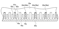
- FIG. 4 is a partially enlarged view of the first cutting blade roll 10a and the second cutting blade roll 10b.
- FIG. 5 is a diagram for explaining the meshing state of the first cutting blade roll 10a and the second cutting blade roll 10b.
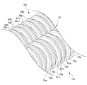
- FIG. 6 is a perspective view for explaining the arrangement of the first scraper 30a and the second scraper 40a.
- FIG. 7 is a perspective view showing a state in which the first scraper 30a and the second scraper 40a are separated.
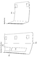
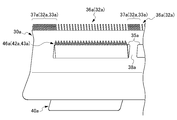
- FIG. 8A is a diagram illustrating the arrangement of teeth in the first scraper 30a and the second scraper 40a.
- FIG. 8B is a partially enlarged view of FIG. 8A.
- FIG. 9A is a diagram illustrating the arrangement of the first tooth group 36a in the first scraper 30a.
- FIG. 9B is a diagram illustrating the arrangement of the second tooth group 37a in the first scraper 30a.
- FIG. 9C is a diagram illustrating the arrangement of teeth in the second scraper 40a.
- FIG. 10 is a perspective view showing the partition member 100.
- FIG. 11 is a perspective view of the state in which the partition member 100 is mounted as viewed from below.
- FIG. 12 is a diagram illustrating a state in which a plurality of raw noodle strings 3 are cut out in the noodle making cutting device 1 according to the first embodiment.
- the noodle making cutting device 1 according to the first embodiment is a device that cuts the noodle band 2 to form a plurality of raw noodle strings 3.
- the cutting device 1 for noodle making according to the first embodiment is an example of a round blade type device having a round blade cutting blade roll (a cutting blade roll having a substantially circular cross section of the cut noodle strings).
- the noodle making cutting device 1 includes a housing 50, a first cutting blade roll 10a, a second cutting blade roll 10b, and a first scraper 30a.
- the second scraper 40a, the third scraper 30b, and the fourth scraper 40b are provided.
- the housing 50 includes a first rectangular frame 56 (see FIG. 3), a second rectangular frame 57 (see FIG. 3), a first horizontal member 51a, a second horizontal member 52a, and a third horizontal member. 51b and a fourth horizontal member 52b.
- the casing 50 is a rod-like or plate-like (block-like) member extending in the axial direction of the first rotation axis C1 of the first cutting blade roll 10a and the second rotation axis C2 of the second cutting blade roll 10b, A rod-like or plate-like (block-like) member (not shown) that extends in a direction orthogonal to the axial direction of the rotation axis C1 and the second rotation axis C2 is provided.
- the first rectangular frame 56 and the second rectangular frame 57 include two pairs of through holes (not shown) through which the shaft members of the first cutting blade roll 10a and the second cutting blade roll 10b are inserted.
- the first cutting blade roll 10a and the second cutting blade roll 10b are rotatably supported by the two pairs of through holes.
- the 1st horizontal member 51a, the 2nd horizontal member 52a, the 3rd horizontal member 51b, and the 4th horizontal member 52b are the rod shape or plate shape extended in the axial direction of the 1st rotating shaft C1 and the 2nd rotating shaft C2 ( It consists of a block-like member.
- the first scraper 30a, the second scraper 40a, the third scraper 30b, and the fourth scraper 40b are respectively connected to the first horizontal member 51a, the second horizontal member 52a, the third horizontal member 51b, and the fourth horizontal member 52b. It is attached.
- a transport conveyor 500 is disposed below the housing 50.
- the first cutting blade roll 10a is configured to be rotatable in the first rotation direction R1 around the first rotation axis C1.
- the first cutting edge roll 10a includes a plurality of first pushing portions (a portion having a narrow groove (shallow groove) in the case of round teeth) 15a formed in the circumferential direction and a plurality of first pushing portions 15a. And a plurality of first insertion portions (a portion having a thick groove (deep groove) in the case of a round tooth) 16a formed between each other.
- the plurality of first pushing portions 15a and the plurality of first insertion portions 16a are formed so as to be alternately arranged in the axial direction of the first rotation axis C1.
- the first cutting blade roll 10a is formed with a plurality of blade portions 70a formed in the circumferential direction, a plurality of thick grooves 81a, and a plurality of fine grooves 82a.
- the thick groove 81a is formed between the predetermined blade part 70a and the blade part 70a adjacent on one side.
- the narrow groove 82a is formed between the predetermined blade part 70a and the adjacent blade part 70a on the other side.
- the blade portion 70a is formed on the inclined portion 71a formed on one side (left side in FIG. 5) of the tip side and on the other side (right side in FIG. 5) of the blade portion 70a.
- the plurality of thick grooves 81a and the plurality of narrow grooves 82a are formed so as to be alternately arranged in the axial direction of the first rotation axis C1.
- the 1st pushing part 15a is comprised by the narrow groove
- the 1st insertion part 16a is comprised by the thick groove
- the plurality of first pushing portions 15a are formed at predetermined intervals in the axial direction of the first rotation axis C1.
- Each of the plurality of first pushing portions 15a is formed between the plurality of first insertion portions 16a. That is, the 1st pushing part 15a and the 1st insertion part 16a are alternately formed continuously in the axial direction of the 1st rotating shaft C1.
- the second cutting blade roll 10b rotates about a second rotation axis C2 parallel to the first rotation axis C1 in a second rotation direction R2 opposite to the first rotation direction R1.
- the second cutting blade roll 10b has a plurality of second pressing portions 15b formed in the circumferential direction, and a plurality of second insertion portions 16b formed between the plurality of second pressing portions 15b, respectively.
- the plurality of second pushing portions 15b and the plurality of second fitting portions 16b are formed so as to be alternately arranged in the axial direction of the second rotation axis C2.
- the second cutting blade roll 10b is formed with a plurality of blade portions 70b formed in the circumferential direction, a plurality of thick grooves 81b, and a plurality of narrow grooves 82b.
- the thick groove 81b is formed between the predetermined blade part 70b and the blade part 70b adjacent on one side.
- the narrow groove 82b is formed between the predetermined blade part 70b and the adjacent blade part 70b on the other side.
- the blade portion 70 b is formed on the inclined portion 71 b formed on one side (right side in FIG. 5) on the tip side and on the other side (left side in FIG. 5) of the blade portion 70 b. And an inclined portion 72b.
- the plurality of thick grooves 81b and the plurality of narrow grooves 82b are formed so as to be alternately arranged in the axial direction of the second rotation axis C2.
- the 2nd pushing part 15b is comprised by the narrow groove
- the 2nd insertion part 16b is comprised by the thick groove
- the plurality of second pushing portions 15b are formed at predetermined intervals in the axial direction of the second rotation axis C2.
- Each of the plurality of second push-in portions 15b is formed between the plurality of second insertion portions 16b. That is, the 2nd pushing part 15b and the 2nd insertion part 16b are alternately formed continuously in the axial direction of the 2nd rotating shaft C2.
- the second cutting blade roll 10 b is disposed so as to mesh with the first cutting blade roll 10 a at a predetermined meshing position 10.
- the meshing position 10 is formed on a plane H including the first rotation axis C1 and the second rotation axis C2.
- each of the plurality of first pushing portions 15a in the first cutting blade roll 10a and each of the plurality of second insertion portions 16b in the second cutting blade roll 10b are as follows: It is in a meshed state. Moreover, in the meshing position 10, each of the plurality of second pressing portions 15b in the second cutting blade roll 10b and each of the plurality of first insertion portions 16a in the first cutting blade roll 10a are in a meshed state.
- the inclined portions of the plurality of blade portions 70a in the first cutting blade roll 10a and the inclined portions of the plurality of blade portions 70b in the second cutting blade roll 10b are close to or in contact with each other. It will be in the state.
- the blade part 70a and the blade part 70b are meshed with each other.
- the narrow groove in the second cutting blade roll 10b with respect to the inclined part inside the blade parts 70a, 70a on both sides constituting the thick groove 81a in the first cutting blade roll 10a The inclined portions on the outer sides of the blade portions 70b on both sides constituting the 82b are in contact with each other.
- the inclined portions on the outer side of the blade portions 70a on both sides constituting the narrow groove 82a are in contact with each other.
- the noodle band 2 (see FIG. 12) is sheared (sheared) into the plurality of raw noodle strings 3 as shown in FIG. Specifically, the noodle band 2 is sheared and formed into a plurality of raw noodle strings 3. The formed raw noodle strings 3 are pushed into the second insertion portion 16b of the second cutting blade roll 10b by the first pushing portion 15a of the first cutting blade roll 10a. The formed raw noodle strings 3 are pushed into the first insertion portion 16a of the first cutting blade roll 10a by the second pushing portion 15b of the second cutting blade roll 10b.
- the raw noodle strings 3 pushed into the respective insertion portions 16b, 16a are formed in a circular shape or a shape close to a circular shape. And the raw noodle strings 3 pushed into each insertion part are scraped out by each scrape mentioned later.
- the one-side inclined portions 71a and 71b formed at the tips of the blade portions 70a and 70b and the other-side inclined portions 72a and 72b are described as having the same angle.
- the present invention is not limited to this.
- the two inclined portions may be configured to have different angles. For example, it is also possible to increase the angle of the inclined parts constituting the pushing parts 15a and 15b (relax the inclination) and reduce the angle of the inclined parts forming the fitting parts 16a and 16b (make the inclination sharp). In this case, since the angle of the two inclined parts constituting the pushing parts 15a and 15b is increased, the raw noodle strings 3 (formed by cutting the noodle band 2) can be suitably pushed into the fitting parts 16b and 16a. it can.
- the first scraper 30a and the second scraper 40a are provided corresponding to the first cutting blade roll 10a.
- the third scraper 30b and the fourth scraper 40b are provided corresponding to the second cutting blade roll 10b.
- Each scrap is attached to the housing 50 so that the angle (contact angle) formed between the tangent to the cutting blade roll into which the tooth tip is inserted and the tooth tip is in the range of about 10 ° to 60 °. Further, in this range, it is preferable that the position of the scrape is appropriately set at a position where the noodle strings are easily scraped and the tooth tip of the scrape is not worn down as much as possible.
- the arrangement and shape of the third scraper 30b and the fourth scraper 40b corresponding to the second cutting blade roll 10b are the arrangement and shape of the first scraper 30a and the second scraper 40a corresponding to the first cutting blade roll 10a, respectively.
- the description regarding the first scraper 30a and the description regarding the second scraper 40a are obtained by replacing “a” at the end of the code with “b” (for example, replacing “32a” with “32b”), respectively. This is used to describe the scraper 30b and the fourth scraper 40b.
- each scraper 30a, 40a, 30b, 40b is formed of a plate-like member having a substantially rectangular shape, and one or a plurality (in this embodiment, 2). A substantially arcuate shape that is bent at a bending line.
- the first scraper 30a includes a first tooth group 36a and a second tooth group 37a at one end thereof.
- the first tooth group 36a includes a plurality of first scraped teeth 32a.
- the plurality of first scraping teeth 32a are inserted and arranged in every other first insertion portion 16a in the axial direction of the first rotation axis C1.
- the second tooth group 37a is formed by alternately arranging a plurality of first scraping teeth 32a and first cleaning teeth 33a.
- the first scraping teeth 32a are inserted and arranged in the first insertion portions 16a in the axial direction of the first rotation axis C1.
- the 1st cleaning tooth 33a is inserted in the narrow groove 82a which comprises the 1st pushing part 15a.
- the first tooth group 36a is disposed at a position corresponding to the first passage hole 35a (second scraper 40a).
- the second tooth group 37a is arranged at a position (including the beam-shaped piece 38a) that does not correspond to the first passage hole 35a. That is, the first tooth group 36a and the second tooth group 37a are alternately arranged in the axial direction of the first rotation axis C1.
- each of the plurality of first scraping teeth 32a and the second scraping teeth 42a described later is “intruded into each of the plurality of first insertion portions 16a (thick grooves 81a) and in close contact with the inner surface of the first insertion portion 16a.
- the 1st cleaning tooth 33a and the 2nd cleaning tooth 43a mentioned below are teeth for taking out the cutting waste which entered into the narrow slot which constitutes a pushing part, and are not the teeth for scraping out noodle strings.
- the first scraper 30a has a plurality of (three in the present embodiment) first passage holes 35a.
- the first passage hole 35a passes the raw noodle strings 3 scraped and dropped from each of the plurality of first insertion portions 16a by the plurality of second scraping teeth 42a of the second scraper 40a to the lower side of the first scraper 30a. It is a hole provided in order to make it.
- the first passage hole 35a is a hole through which the second scraper 40a is inserted.
- the second scraper 40a includes a third tooth group 46a at one end thereof.
- the third tooth group 46 a is formed by arranging a plurality of second scraping teeth 42 a and second cleaning teeth 43 a in a state where the first scraper 30 a and the second scraper 40 a are attached to the housing 50.
- the second scraping teeth 42a are inserted and arranged in the remaining first insertion portions 16a in which the plurality of first scraping teeth 32a in the first scraper 30a are not inserted and arranged.
- the 2nd cleaning tooth 43a is inserted in the narrow groove 82a which comprises the 1st pushing part 15a.
- the first scraped teeth 32a and the second scraped teeth 42a are arranged so that the first scraped teeth 32a of the first scraper 30a and the second scraped teeth 42a of the second scraper 40a are inserted and arranged in the same first insertion portion 16a. May be provided.
- the first insertion portion 16a has either one of the first scraping teeth 32a or the second scraping teeth 42a. It does not scrape the noodle strings, but functions as cleaning teeth (cleaning teeth) for cutting waste remaining in the thick grooves.
- the arrangement of the scraped teeth and the cleaning teeth is not particularly limited as long as the noodle strings can be scraped and the scraped scraps can be cleaned.
- the first scraper 30a is fixed at a first fixing position 53a in the housing 50.
- the 1st fixed position 53a in this embodiment is the 1st horizontal member 51a.
- the second scraper 40 a is fixed at a second fixing position 54 a in the housing 50.
- the second fixed position 54a in the present embodiment is the second horizontal member 52a.
- the second horizontal member 52 a is disposed on the outer side HX in the horizontal direction than the meshing position 10.
- the “outside in the horizontal direction” refers to a direction away from the meshing position 10 in the horizontal direction H orthogonal to the first rotation axis C1 and the second rotation axis C2.
- the first scraper 30a is fixed to the first horizontal member 51a by a fixing bolt B1.
- a washer member B11 is interposed between the first horizontal member 51a and the fixing bolt B1.
- the second scraper 40a is fixed to the second horizontal member 52a with a fixing bolt B2.
- a washer member B21 is interposed between the second horizontal member 52a and the fixing bolt B2.
- the first fixed position 53a is located on the outer side HX in the horizontal direction from the position of the second tooth tip 44a of the second scraping tooth 42a. In the horizontal direction H, the distance from the position of the second tooth tip 44a of the second scraping tooth 42a to the first fixed position 53a was scraped from the first cutting blade roll 10a by the second scraping tooth 42a of the second scraper 40a. It is set as appropriate based on the trajectory of the noodle strings moving.
- the first fixed position 53a is located below the first cutting blade roll 10a.
- a plurality (three in this embodiment) of second scrapers 40a are arranged along the first rotation axis C1.
- the first passage holes 35a correspond to the plurality of (three in the present embodiment) second scrapers 40a, and a plurality (three in the present embodiment) along the first rotation axis C1.
- a beam-shaped piece 38a is provided between the first passage holes 35a and 35a adjacent to each other along the first rotation axis C1.
- the second fixed position 54a is located on the outer side HX in the horizontal direction than the first fixed position 53a.
- the second scraper 40a is farther from the first cutting blade roll 10a than the first scraper 30a at the second fixed position 54a.
- the second scraping tooth 42a side of the second scraper 40a extends from the opposite side of the first scraper 30a to the first cutting blade roll 10a side through the first passage hole 35a. It extends. That is, the second scraper 40a intersects the first scraper 30a via the first passage hole 35. Further, the second scraper 40a passes through a position in the vicinity of the edge of the horizontal outside HX in the first passage hole 35a. Thereby, the opening area of the 1st passage hole 35a can be ensured to the maximum.
- each of the plurality of first tooth tips 34a which is the tooth tip of each of the plurality of first scraped teeth 32a, starts from the meshing position 10 around the first rotation axis C1. It is arranged at a position (11a) of 5 ° to 90 °, preferably 30 ° to 60 ° in one rotation direction R1.
- each of the plurality of second tooth tips 44a which are the tooth tips of each of the plurality of second scraping teeth 42a, is moved from the meshing position 10 to the first rotation direction R1 about the first rotation axis C1. It is arranged at a position (12a) of 30 ° to 90 °, preferably 45 ° to 60 °.
- the second scraper 40a is disposed such that the position 12a of the second tooth tip 44a is separated from the position 11a of the first tooth tip 34a by 30 ° or more in the first rotation direction R1 around the first rotation axis C1.
- the tooth tip position is a position facing the tooth tip on the bottom surface of each insertion portion.
- the description regarding the first scraper 30a and the second scraper 40a is incorporated in the description of the third scraper 30b and the fourth scraper 40b, respectively, but the main configuration of the third scraper 30b and the fourth scraper 40b. This will be described below.
- the third scraper 30b and the fourth scraper 40b are arranged with respect to the second cutting blade roll 10b in the same positional relationship as the first scraper 30a and the second scraper 40a.
- the rotation axis is the second rotation axis C2
- the rotation direction is the second rotation direction R2.
- the third scraper 30b has a second passage hole 35b.
- the second passage hole 35b passes the raw noodle strings 3 scraped and dropped from each of the plurality of second insertion portions 16b by the plurality of fourth scraping teeth 42b of the fourth scraper 40b to the lower side of the third scraper 30b. It is a hole provided in order to make it.
- a plurality of (three) fourth scrapers 40b are arranged along the second rotation axis C2.
- a plurality (three) of second passage holes 35b are provided along the second rotation axis C2 corresponding to the plurality of fourth scrapers 40b.
- the second passage holes 35b, 35b adjacent to each other along the second rotation axis C2 are discontinuous.
- the third fixed position 53b is located on the outer side HX in the horizontal direction with respect to the position of the fourth tooth tip 44b of the fourth scraping tooth 42b.
- the fourth fixed position 54b is located below the second cutting blade roll 10b.
- the fourth fixed position 54b is located on the outer side HX in the horizontal direction than the third fixed position 53b.
- the fourth scraper 40b is farther from the second cutting blade roll 10b than the third scraper 30b at the fourth fixed position 54b.
- the fourth scraping tooth 42b side of the fourth scraper 40b extends from the opposite side of the third scraper 30b from the second cutting blade roll 10b to the second cutting blade roll 10b side via the second passage hole 35b. Yes.
- the fourth scraper 40b passes through a position in the vicinity of the edge of the horizontal outside HX in the second passage hole 35b.
- the partition member 100 is used to partition the noodle strings 3 cut by the two cutting blade rolls 10a and 10b and scraped by the scrapers 30a, 40a, 30b, and 40b into a predetermined width (amount). More specifically, as shown in FIG. 10, the partition member 100 fixes a plurality of partition plates 110 arranged in parallel, a connection member 120 that connects the plurality of partition plates 110, and the connection member 120 to the housing 50. A partition fixing member 130.
- the plurality of partition plates 110 are arranged so as to be orthogonal to both the rotation axes C1 and C2.
- a plurality of partition plates 110 divide the space below the casing 50, particularly the spaces below the scrapers 30a, 40a, 30b, and 40b, into a plurality of spaces 150 that are arranged along both rotation axes C1 and C2. be able to.
- the noodle strings 3 scraped by the scrapes can be partitioned into a predetermined width (amount).
- the operation of the noodle making cutting device 1 will be described with reference to FIG. As shown in FIG. 12, the noodle band 2 put into the meshing position 10 of the first cutting blade roll 10 a and the second cutting blade roll 10 b in the noodle making cutting device 1 is sheared (cut) at the meshing position 10. As a result, a plurality of raw noodle strings 3 are formed.
- the plurality of raw noodle strings 3 formed by shearing (cutting) are inserted into the plurality of first insertion portions 16a in the first cutting blade roll 10a and the plurality of second insertion portions 16b in the second cutting blade roll 10b. Is done.
- the first cutting blade roll 10a in which the plurality of raw noodle strings 3 are inserted into the first insertion portion 16a is rotated in the first rotation direction R1 about the first rotation axis C1.
- a portion of the raw noodle strings 3 that has been rotationally moved along with the rotation of the first cutting blade roll 10a is first scraped out by the first scraper 30a.
- the raw noodle strings 3 scraped out by the first scraper 30a hang down substantially vertically downward and fall onto the transport conveyor 500 via the space between the first scraper 30a and the third scraper 30b.
- the remaining raw noodle strings 3 that have been rotationally moved with the further rotation of the first cutting blade roll 10a are scraped out by the second scraper 40a.
- the raw noodle strings 3 scraped out by the second scraper 40a hang down substantially vertically downward, pass through the first passage hole 35a of the first scraper 30a, and drop onto the conveyor 500.
- the second cutting blade roll 10b in which the plurality of raw noodle strings 3 are inserted into the second insertion portion 16b is rotated in the second rotation direction R2 around the second rotation axis C2.
- a portion of the raw noodle strings 3 that has been rotationally moved along with the rotation of the second cutting blade roll 10b is first scraped out by the third scraper 30b.
- the raw noodle strings 3 scraped out by the third scraper 30b hang down substantially vertically downward and fall onto the transport conveyor 500 through the space between the first scraper 30a and the third scraper 30b.
- the remaining raw noodle strings 3 that have been rotationally moved with the further rotation of the second cutting blade roll 10b are scraped out by the fourth scraper 40b.
- the raw noodle strings 3 scraped by the fourth scraper 40b hang down substantially vertically downward, pass through the second passage hole 35b of the third scraper 30b, and drop onto the conveyor 500.
- a plurality of raw noodle strings 3 formed by the noodle making cutting device 1 are cut out on a belt 510 (to be described later) in the conveyor 500.
- the raw noodle strings 3 scraped by the first scraper 30a, the second scraper 40a, the third scraper 30b, and the fourth scraper 40b are layered downward in the order of scraping. It is placed on the belt 510 and is transported in a state where it generally overlaps four layers. The plurality of raw noodle strings 3 cut out are transported to a subsequent process as the belt 510 moves.
- the noodle strip formation process which rolls noodle dough and forms a noodle strip is mentioned, for example.
- the post-process include a steaming process for raw noodle strings, a process for cooling steamed noodle strings, a process for stretching noodle strings, a process for cutting noodle strings in the length direction, a process for drying noodles, and a process for packaging noodles. It is done.
- the first fixing position 53a of the first scraper 30a is located on the outer side HX in the horizontal direction with respect to the position of the second tooth tip 44a of the second scraping tooth 42a.
- the third fixed position 53b of the third scraper 30b is located on the outer side HX in the horizontal direction with respect to the position of the fourth tooth tip 44b of the fourth scraping tooth 42b.
- the first scraper 30a has the first passage hole 35a.
- the third scraper 30b has a second passage hole 35b. Therefore, the raw noodle strings 3 scraped and dropped from each of the plurality of first insertion portions 16a by the plurality of second scraping teeth 42a of the second scraper 40a can be passed to the lower side of the first scraper 30a. Moreover, the raw noodle strings 3 scraped and dropped from each of the plurality of second insertion portions 16b by the plurality of fourth scraping teeth 42b of the fourth scraper 40b can be passed to the lower side of the third scraper.
- the second scraper 40a intersects the first scraper 30a via the first passage hole 35a, and the fourth scraper 40b It intersects with the third scraper 30b via the two passage holes 35b.
- the wear of the tooth tip is large due to the influence of the angle (contact angle) formed between the tangent to the cutting blade roll into which the tooth tip of the scrap is inserted and the tooth tip.
- 40b can be replaced without removing the first scraper 30a and the third scraper 30b, which are less frequently replaced. For this reason, it is possible to improve the efficiency of maintenance work related to replacement of scraps.
- first scraper 30a in the first embodiment is referred to as “first scraper 230a” in the second embodiment.
- the description about the first embodiment is appropriately applied to points that are not particularly described in other embodiments. Also in other embodiments, the same effects as in the first embodiment can be obtained.
- FIG. 13A is a bottom view showing the first scraper 230a and the second scraper 240a in the second embodiment.
- FIG. 13B is a partially enlarged view of FIG. 13A.
- the noodle making cutting device of the second embodiment is mainly composed of one first passage hole 235a, as compared with the noodle making cutting device 1 of the first embodiment.
- the number of the second scrapes 240a arranged in is different.
- one first passage hole 235a is provided in one first scraper 230a. Accordingly, the first scraper 230a does not include the beam-like piece 38a in the first embodiment. Further, the first scraper 230a does not include the second tooth group 37a provided corresponding to the beam-like piece 38a.
- the length of the 1st passage hole 235a in a 2nd embodiment is about 3 times the length of the 1st passage hole 35a in a 1st embodiment, for example.
- three second scrapers 240a are arranged with respect to the first passage hole 235a of one first scraper 230a.
- the three second scrapers 40a are arranged with substantially no gap in the axial direction of the first rotation axis C1.
- the first scraping is performed as in the first embodiment. It is not necessary to provide the second tooth group 37a in which the teeth 32a and the first cleaning teeth 33a are alternately arranged at a position corresponding to the beam-shaped piece 38a. Therefore, the occurrence of binding of noodle strings can be suppressed as compared with the first embodiment in which binding of noodle strings is likely to occur in the second tooth group 37a.
- the three second scrapers 240a are arranged with respect to the first passage holes 235a of the one first scraper 230a, for example, when one second scraper 240a is damaged, one damaged one It is sufficient to replace only the second scraper 240a, and the second scraper 240a can be replaced efficiently.
- FIG. 14A is a bottom view showing the first scraper 330a and the second scraper 340a in the third embodiment.
- 14B is a partially enlarged view of FIG. 14A.
- the noodle making cutting device of the third embodiment is mainly 1 in one first scraper 330 a as compared with the noodle making cutting device of the second embodiment.
- a difference is that one first passage hole 335a is provided, and one second scraper 340a is arranged in one first passage hole 335a.
- one first passage hole 335a is provided in one first scraper 330a, as in the second embodiment.
- the length of the 1st passage hole 335a in 3rd Embodiment is about 3 times the length of the 1st passage hole 35a in 1st Embodiment, for example.
- one second scraper 340a is inserted into the first passage hole 335a of one first scraper 330a.
- the length of the second scraper 340a in the third embodiment is, for example, about three times the length of the second scraper 40a in the first embodiment. According to the third embodiment, the number of scrapes can be suppressed.
- FIG. 15 is a cross-sectional view illustrating the structure of the noodle making cutting device 401 according to the fourth embodiment.
- FIG. 16 is a diagram illustrating a state where a plurality of raw noodle strings 3 are cut out in the noodle making cutting device 401 according to the fourth embodiment.
- the noodle making cutting device 401 of the fourth embodiment is mainly configured so that the second scraper 440 a is different from the first scraper 430 a in comparison with the noodle making cutting device 1 of the first embodiment. The difference is that the first passage hole 435a is not inserted and the fourth scraper 440b is not inserted through the second passage hole 435b of the third scraper 430b.
- the second fixed position 454a is located on the outer side HX in the horizontal direction than the first fixed position 453a.
- the second scraper 440a is closer to the first cutting blade roll 410a than the first scraper 430a at the second fixed position 454a. Therefore, the second scraper 440a is positioned closer to the first cutting blade roll 410a than the first scraper 430a without inserting the first passage hole 435a of the first scraper 430a.
- the fourth fixed position 454b is located on the outer side HX in the horizontal direction than the third fixed position 453b.
- the fourth scraper 440b is closer to the second cutting blade roll 410b than the third scraper 430b at the fourth fixed position 454b. Therefore, the fourth scraper 440b is positioned closer to the second cutting blade roll 410b than the third scraper 430b without inserting the second passage hole 435b of the third scraper 430b.
- the first passage hole 435a of the first scraper 430a is scraped and dropped from each of the plurality of first insertion portions 416a by the plurality of second scraping teeth 442a of the second scraper 440a. It is provided only for passing the raw noodle string 3 to the lower side of the first scraper 430a.
- the second passage hole 435b of the third scraper 430b passes the raw noodle strings 3 that are scraped and dropped from each of the plurality of second insertion portions 416b by the plurality of second scraping teeth 442b of the fourth scraper 440b. It is provided only for passing through the lower side of the three scrapers 430b.
- the noodle making cutting device 401 mainly includes the arrangement relationship between the first scraper 430a and the second scraper 440a and the third scraper 430b and the fourth scraper. Except for the point that the arrangement relationship with 440b is different, it operates in the same manner as the noodle making cutting device 1 of the first embodiment.
- the noodle making cutting device of each of the above-described embodiments is a round blade type device in which the cut surface of the noodle strings is substantially circular, but is not limited thereto.
- the noodle making cutting device of the present invention can be applied to, for example, a square blade type, a knife blade type, and other types of devices having a square cross section.
- FIG. 17A is a diagram illustrating the arrangement of the first scraping teeth 632a in the first scraper 630a in the cutting blade roll of a square blade.
- FIG. 17B is a diagram illustrating the arrangement of the second scraping teeth 642a in the second scraper 640a in the cutting blade roll of a square blade.
- the square-tooth type cutting blade roll 610a has convex portions (ridges) and concave portions (grooves) having a rectangular cross section alternately in the direction of the rotation axis (not shown). Formed.
- the portion corresponding to the pushing portion 15a (the portion including the narrow groove) of the noodle making cutting device 1 (round blade type) of the first embodiment described above is a convex portion 615a.
- a portion corresponding to the fitting portion (a portion including the thick groove) 16a is a concave portion 616a.
- the push-in part does not have a narrow groove in the round blade type. For this reason, each scrape does not have the cleaning teeth of the narrow groove portion, and has only the scraped teeth 632a and 642a.
- the cross section of the cutting blade roll 610a in the direction perpendicular to the rotation axis is substantially the same as the cross section shown in FIG. 1 relating to the round blade type noodle making cutting device 1.
- the square tooth type noodle making cutting device is configured such that the first cutting blade roll and the second cutting blade roll mesh with each other at the meshing position, and the pushing portion (convex portion). 615a) pushes a thin noodle band into the mating part (recess 616a) of the counterpart roll and shears it into a line to form a noodle string.
- the noodle band (noodle string) pushed into the fitting portion (recess 616a) is disposed with respect to the first scraper 630a and the second scraper 640a disposed with respect to the first cutting blade roll 610a, and the second cutting blade roll.
- the scraped teeth of the third and fourth scraped pieces are scraped and cut out.
- the scraping teeth 632a of the first scraper 630a are inserted and arranged every other in the direction of the first rotating shaft (not shown) in the fitting portion (recess 616a) of the first cutting blade roll 610a. Further, the scraping teeth 642a of the second scraper 640a are inserted and disposed in the insertion portion (recessed portion 616a) where the scraping teeth 632a are not inserted.
- the noodle strings are scraped in the order of the first scraper 630a and the second scraper 640a in accordance with the rotation of the first cutting blade roll 610a. It is scraped by 632a and 642a, and cut out separately. Also in the second cutting blade roll, the noodle strings are similarly divided and cut out by the third and fourth scrapers. And after that, it is the same as that of the case of the above-mentioned round blade.
- the structure As for the scraping teeth 642a of the second scraper 640a (fourth scraper), as in the case of the round blade, the structure (indicated by the broken line portion in FIG. 17B) is inserted and disposed in all the fitting portions (recesses 616a). It is good also as a structure which has the tooth
- the cutting device for noodle making according to the present invention is most effectively used for steamed noodles that are easily bound and firmly bound, and instant noodles obtained by drying steamed noodles. It can be preferably used. For example, even in the case of raw noodles, it binds if it is not dusted enough, and even in the case of boiled noodles, when boiled while being transported as a continuous noodle string, adjacent noodle strings are bound together In such a case, the noodle cutting device of the present invention is effective.
- the 1st cutting blade roll 10a is arrange
- the 2nd cutting blade roll 10b is arrange
- the 1st cutting blade roll 10a may be arrange
- the 2nd cutting blade roll 10b may be arrange
- the 1st cutting blade roll 10a and the 2nd cutting blade roll 10b are arranged horizontally in the above-mentioned 1st Embodiment, it is not restricted to this, For example, the plane which connects the rotating shaft of both rolls You may arrange in H in the state which inclined about 45 degrees or less with respect to the horizontal direction.
- the positions of the scrapes are arranged symmetrically with respect to the first cutting blade roll 10a and the second cutting blade roll 10b in a plane perpendicular to the rotation axis of the both cutting blade rolls.
- it does not have to be arranged symmetrically.
- the tooth tips of the first scraper 30a and the tooth tips of the third scraper 30b may be arranged at different angles from the meshing position 10, respectively.
- the tooth tips of the second scraper 40a and the tooth tips of the fourth scraper 40b may be arranged at different angles from the meshing position 10, respectively.
Landscapes
- Life Sciences & Earth Sciences (AREA)
- Engineering & Computer Science (AREA)
- Forests & Forestry (AREA)
- Mechanical Engineering (AREA)
- Food Science & Technology (AREA)
- Manufacturing And Processing Devices For Dough (AREA)
- Noodles (AREA)
- Crushing And Pulverization Processes (AREA)
Abstract
Description
具体的には、特許文献1及び2に記載の技術では、1個のカスリにおける櫛歯(掻き出し歯)の長さを隣同士で異ならせているため、特に、長さの長い方の掻き出し歯において、金属疲労などにより、掻き出し歯が折れたり、曲がったりして破損するという問題点がある。
具体的には、切刃ロール同士の噛合位置(噛み合う位置)に近い位置に設置されているカスリが種々の障害となる。例えば、カスリにより切刃ロールから掻き出されて落下する麺線は、噛合位置に近いカスリやその固定位置(カスリが筐体に固定される部分)に引っ掛かり、切り出された麺線を搬送するベルトコンベア等に落下しなくなることがある。
以下、本発明の製麺用切出装置の第1実施形態について説明する。図1は、第1実施形態の製麺用切出装置1の構造を説明する断面図である。図2は、図1に示す製麺用切出装置1を下方から視た斜視図である。図3は、第1切刃ロール10a及び第2切刃ロール10bを説明する平面図である。図4は、第1切刃ロール10a及び第2切刃ロール10bの部分拡大図である。図5は、第1切刃ロール10aと第2切刃ロール10bとの噛み合い状態を説明する図である。図6は、第1カスリ30a及び第2カスリ40aの配置を説明する斜視図である。図7は、第1カスリ30aと第2カスリ40aとを分離させた状態を示す斜視図である。
まず、図1から図11により、第1実施形態の製麺用切出装置1の構成について説明する。
第1実施形態の製麺用切出装置1は、丸刃の切刃ロール(切り出された麺線の断面が略円形になる切刃ロール)を有する丸刃タイプの装置における一例である。
筐体50は、第1矩形フレーム56(図3参照)と、第2矩形フレーム57(図3参照)と、第1横架部材51aと、第2横架部材52aと、第3横架部材51bと、第4横架部材52bと、を備える。また、筐体50は、第1切刃ロール10aの第1回転軸C1及び第2切刃ロール10bの第2回転軸C2の軸方向に延びる棒状又は板状(ブロック状)の部材、第1回転軸C1及び第2回転軸C2の軸方向と直交する方向に延びる棒状又は板状(ブロック状)の部材など(いずれも図示せず)を備える。
第1カスリ30a、第2カスリ40a、第3カスリ30b及び第4カスリ40bは、それぞれ第1横架部材51a、第2横架部材52a、第3横架部材51b及び第4横架部材52bに取り付けられる。
筐体50の下方には、搬送コンベア500が配置される。
また、複数の太溝81a及び複数の細溝82aそれぞれは、第1回転軸C1の軸方向において、交互に並ぶように形成される。
また、第1嵌入部16aは、太溝81aと、太溝81aにおける先端側に太溝81aの側面と連続して形成される傾斜部72a及び傾斜部71aと、により構成される。
また、複数の太溝81b及び複数の細溝82bそれぞれは、第2回転軸C2の軸方向において、交互に並ぶように形成される。
また、第2嵌入部16bは、太溝81bと、太溝81bにおける先端側に太溝81bの側面と連続して形成される傾斜部72b及び傾斜部71bと、により構成される。
同様に、刃部70aと刃部70bとの噛み合いにおいて、第2切刃ロール10bにおける太溝81bを構成する両側の刃部70b、70bの内側の傾斜部に対して、第1切刃ロール10aにおける細溝82aを構成する両側の刃部70a、70aの外側の傾斜部は、当接している。
各嵌入部16b、16aに押し込まれた生麺線3は、断面が円形又は円形に近い形状に形成される。そして、各嵌入部に押し込まれた生麺線3は、後述する各カスリにより掻き出される。
図1、図2及び図6から図8Bに示すように、各カスリ30a,40a,30b,40bは、略矩形状を有する板状の部材からなり、1本又は複数本(本実施形態では2本)の屈曲線において屈曲した略弧状の形状を有する。
また、第1カスリ30a及び第2カスリ40aにおいて、掻き出し歯及び清掃歯の配列は、麺線の掻き出し及び切りカスの清掃ができれば、特に制限されない。
第1カスリ30aは、第1横架部材51aに固定ボルトB1により固定される。第1横架部材51aと固定ボルトB1との間には、ワッシャー部材B11が介在される。第2カスリ40aは、第2横架部材52aに固定ボルトB2により固定される。第2横架部材52aと固定ボルトB2との間には、ワッシャー部材B21が介在される。
第1カスリ30aにおいて、第1通過孔35aは、複数個(本実施形態では3個)の第2カスリ40aに対応して、第1回転軸C1に沿って複数個(本実施形態では3個)設けられる。第1回転軸C1に沿って隣接する第1通過孔35a,35aの間には、梁状片38aが設けられる。この梁状片38aが設けられることにより、第1通過孔35aを設けることによる第1カスリ30aの強度の低下を低減する(第1カスリ30aを補強する)ことができる。また、梁状片38aが設けられることで、隣接する第1通過孔35a,35a同士は、非連続となっている。
また、第2カスリ40aは、第1通過孔35aにおける水平方向外側HXの端縁近傍の位置を通過する。これにより、第1通過孔35aの開口面積を最大限に確保することができる。
ここで、歯先位置は、各嵌入部の底面における歯先に対向する位置である。
第3カスリ30b及び第4カスリ40bは、第1カスリ30a及び第2カスリ40aと同様の位置関係で、第2切刃ロール10bに対して配置される。この場合、回転軸は第2回転軸C2であり、回転方向は第2回転方向R2である。
第3カスリ30bにおいて、第2通過孔35bは、複数の第4カスリ40bに対応して第2回転軸C2に沿って複数個(3個)設けられる。第2回転軸C2に沿って隣接する第2通過孔35b,35b同士は、非連続となっている。
第3固定位置53bは、第4掻き出し歯42bの第4歯先44bの位置よりも水平方向外側HXに位置する。第4固定位置54bは、第2切刃ロール10bよりも下方に位置する。
詳述すると、図10に示すように、仕切り部材100は、平行に配列する複数の仕切り板110と、複数の仕切り板110を連結する連結部材120と、連結部材120を筐体50に固定させる仕切り固定部材130と、を備える。
複数の仕切り板110の間隔などを適宜設定することにより、カスリにより掻き出された麺線3を所定の幅(量)に仕切ることができる。
図12に示すように、製麺用切出装置1における第1切刃ロール10aと第2切刃ロール10bとの噛合位置10に投入された麺帯2は、噛合位置10においてせん断(切断)され、複数の生麺線3が形成される。
切り出された複数の生麺線3は、ベルト510の移動に伴って、後工程に搬送される。
前工程としては、例えば、麺生地を圧延して麺帯を形成する麺帯形成工程が挙げられる。
後工程としては、例えば、生麺線の蒸煮工程、蒸煮された麺線の冷却工程、麺線の引き伸ばし工程、麺線の長さ方向のカット工程、麺の乾燥工程、麺の包装工程が挙げられる。
第1実施形態における製麺用切出装置1においては、第1カスリ30aの第1固定位置53aは、第2掻き出し歯42aの第2歯先44aの位置よりも水平方向外側HXに位置すると共に、第3カスリ30bの第3固定位置53bは、第4掻き出し歯42bの第4歯先44bの位置よりも水平方向外側HXに位置する。
他の実施形態において特に説明しない点は、第1実施形態についての説明が適宜適用される。また、他の実施形態においても、第1実施形態と同様の効果が奏される。
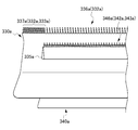
次に、第2実施形態について説明する。図13Aは、第2実施形態における第1カスリ230a及び第2カスリ240aを示す底面図である。図13Bは、図13Aの部分拡大図である。
図13A及び図13Bに示すように、第2実施形態の製麺用切出装置は、第1実施形態の製麺用切出装置1に比して、主として、1個の第1通過孔235aに配置される第2カスリ240aの個数が異なる。
第2実施形態における第1通過孔235aの長さは、例えば、第1実施形態における第1通過孔35aの長さの約3倍である。第2実施形態においては、1個の第1カスリ230aの第1通過孔235aに対して3個の第2カスリ240aが配置される。3個の第2カスリ40aは、第1回転軸C1の軸方向に実質的に隙間無く配列している。
次に、第3実施形態について説明する。図14Aは、第3実施形態における第1カスリ330a及び第2カスリ340aを示す底面図である。図14Bは、図14Aの部分拡大図である。
図14A及び図14Bに示すように、第3実施形態の製麺用切出装置は、第2実施形態の製麺用切出装置に比して、主として、1個の第1カスリ330aに1個の第1通過孔335aが設けられ、1個の第1通過孔335aに1個の第2カスリ340aが配置される点が異なる。
第3実施形態によれば、カスリの個数を抑制することができる。
次に、第4実施形態について説明する。図15は、第4実施形態の製麺用切出装置401の構造を説明する断面図である。図16は、第4実施形態の製麺用切出装置401において複数の生麺線3が切り出される状態を説明する図である。
図15に示すように、第4実施形態の製麺用切出装置401は、第1実施形態の製麺用切出装置1に比して、主として、第2カスリ440aが第1カスリ430aの第1通過孔435aを挿通していないと共に、第4カスリ440bが第3カスリ430bの第2通過孔435bを挿通していない点が異なる。
角刃タイプの場合、押込部は丸刃タイプにおける細溝を有さない。このため、各カスリは、細溝部の清掃歯を有さず、掻き出し歯632a、642aのみを有する。
丸刃タイプの製麺用切出装置と同様に、角歯タイプの製麺用切出装置は、第1切刃ロールと第2切刃ロールとが噛合位置で噛み合うと共に、押込部(凸部615a)が相手方のロールの嵌入部(凹部616a)に薄い麺帯を押し込んで線状にせん断して、麺線を形成する。嵌入部(凹部616a)に押し込まれた麺帯(麺線)は、第1切刃ロール610aに対して配置された第1カスリ630a及び第2カスリ640a、並びに第2切刃ロールに対して配置された第3カスリ及び第4カスリそれぞれの掻き出し歯によって、掻き出されて切り出される。
また、第1切刃ロール10aと第2切刃ロール10bとは、上述の第1実施形態においては水平に配列しているが、これに制限されず、例えば、両ロールの回転軸を結ぶ平面Hが水平方向に対して45°以下程度傾いた状態で、配列してもよい。
Claims (5)
- 筐体と、
第1回転軸を中心に第1回転方向へ回転可能であって、円周方向に形成された複数の第1押込部と前記複数の第1押込部同士の間にそれぞれ形成された複数の第1嵌入部とを有する第1切刃ロールと、
前記第1回転軸に平行な第2回転軸を中心に前記第1回転方向と反対の第2回転方向へ回転可能であって、円周方向に形成された複数の第2押込部と前記複数の第2押込部同士の間にそれぞれ形成された複数の第2嵌入部とを有すると共に、前記第1切刃ロールと噛合位置で噛み合うように配置された第2切刃ロールと、
前記複数の第1嵌入部に挿入配置される複数の第1掻き出し歯を有すると共に前記筐体に第1固定位置において固定される第1カスリと、
前記複数の第1掻き出し歯が挿入配置されない残りの第1嵌入部それぞれに挿入配置される複数の第2掻き出し歯を有すると共に、前記複数の第2掻き出し歯の第2歯先それぞれが前記複数の第1掻き出し歯の第1歯先それぞれよりも前記第1回転軸を中心に前記噛合位置から第1回転方向の下流側の位置に配置され、前記筐体に第2固定位置において固定される第2カスリと、
前記複数の第2嵌入部に挿入配置される複数の第3掻き出し歯を有すると共に前記筐体に第3固定位置において固定される第3カスリと、
前記複数の第3掻き出し歯が挿入配置されない残りの第2嵌入部それぞれに挿入配置される複数の第4掻き出し歯を有すると共に、前記複数の第4掻き出し歯の第4歯先それぞれが前記複数の第3掻き出し歯の第3歯先それぞれよりも前記第2回転軸を中心に前記噛合位置から第2回転方向の下流側の位置に配置され、前記筐体に第4固定位置において固定される第4カスリと、を備え、
前記第1カスリは、前記第2カスリの複数の第2掻き出し歯により前記複数の第1嵌入部それぞれから掻き出されて落下する麺線を前記第1カスリの下方側に通過させる第1通過孔を有し、
前記第3カスリは、前記第4カスリの複数の第4掻き出し歯により前記複数の第2嵌入部それぞれから掻き出されて落下する麺線を前記第3カスリの下方側に通過させる第2通過孔を有し、
前記第1回転軸及び前記第2回転軸に直交する水平方向において前記噛合位置から離れる方向を水平方向外側という場合に、
前記第1固定位置は、前記第2掻き出し歯の第2歯先の位置よりも水平方向外側に位置すると共に、前記第3固定位置は、前記第4掻き出し歯の第4歯先の位置よりも水平方向外側に位置する
製麺用切出装置。 - 前記第2カスリは、前記第1通過孔を介して前記第1カスリにおける前記第1切刃ロールとは反対側から前記第1切り刃ロール側に亘って延びており、
前記第4カスリは、前記第2通過孔を介して前記第3カスリにおける前記第2切刃ロールとは反対側から前記第2切り刃ロール側に亘って延びている
請求項1に記載の製麺用切出装置。 - 前記第2固定位置は、前記第1固定位置よりも水平方向外側に位置すると共に、
前記第4固定位置は、前記第3固定位置よりも水平方向外側に位置する
請求項2に記載の製麺用切出装置。 - 前記第2カスリは、前記第1回転軸に沿って複数配列され、
前記第1通過孔は、前記複数の第2カスリに対応して前記第1回転軸に沿って複数設けられ、前記第1回転軸に沿って隣接する前記第1通過孔同士は、非連続となっており、
前記第4カスリは、前記第2回転軸に沿って複数個配列され、
前記第2通過孔は、前記複数の第4カスリに対応して前記第2回転軸に沿って複設けられ、前記第2回転軸に沿って隣接する前記第2通過孔同士は、非連続となっている
請求項2又は3に記載の製麺用切出装置。 - 前記第2カスリは、前記第1カスリよりも前記第1切刃ロール側に位置しており、
前記第4カスリは、前記第3カスリよりも前記第2切刃ロール側に位置している
請求項1に記載の製麺用切出装置。
Priority Applications (7)
| Application Number | Priority Date | Filing Date | Title |
|---|---|---|---|
| HK11106944.1A HK1152842B (zh) | 2009-06-16 | 2009-10-29 | 切面装置 |
| KR1020117003392A KR101247096B1 (ko) | 2009-06-16 | 2009-10-29 | 제면용 절출장치 |
| EP09846128.8A EP2314168B1 (en) | 2009-06-16 | 2009-10-29 | Cutting device for noodle production |
| CN200980000571.2A CN102083318B (zh) | 2009-06-16 | 2009-10-29 | 切面装置 |
| BRPI0912442-0A BRPI0912442B1 (pt) | 2009-06-16 | 2009-10-29 | aparelhagem para corte de noodle |
| MX2011001776A MX2011001776A (es) | 2009-06-16 | 2009-10-29 | Aparato para cortar tallarines. |
| US13/058,089 US9867380B2 (en) | 2009-06-16 | 2009-10-29 | Apparatus for cutting out noodle |
Applications Claiming Priority (2)
| Application Number | Priority Date | Filing Date | Title |
|---|---|---|---|
| JP2009143020A JP4438018B1 (ja) | 2009-06-16 | 2009-06-16 | 製麺用切出装置 |
| JP2009-143020 | 2009-06-16 |
Publications (1)
| Publication Number | Publication Date |
|---|---|
| WO2010146635A1 true WO2010146635A1 (ja) | 2010-12-23 |
Family
ID=42193850
Family Applications (1)
| Application Number | Title | Priority Date | Filing Date |
|---|---|---|---|
| PCT/JP2009/005731 Ceased WO2010146635A1 (ja) | 2009-06-16 | 2009-10-29 | 製麺用切出装置 |
Country Status (11)
| Country | Link |
|---|---|
| US (1) | US9867380B2 (ja) |
| EP (1) | EP2314168B1 (ja) |
| JP (1) | JP4438018B1 (ja) |
| KR (1) | KR101247096B1 (ja) |
| CN (1) | CN102083318B (ja) |
| BR (1) | BRPI0912442B1 (ja) |
| HU (1) | HUE028197T2 (ja) |
| MX (1) | MX2011001776A (ja) |
| RU (1) | RU2459412C1 (ja) |
| TW (1) | TWI414240B (ja) |
| WO (1) | WO2010146635A1 (ja) |
Cited By (2)
| Publication number | Priority date | Publication date | Assignee | Title |
|---|---|---|---|---|
| US20130202765A1 (en) * | 2012-02-07 | 2013-08-08 | Sanyo Foods Co., Ltd. | Noodles and apparatus for processing the same |
| WO2015068402A1 (ja) * | 2013-11-08 | 2015-05-14 | 日清食品ホールディングス株式会社 | 麺線切出し装置および生麺 |
Families Citing this family (17)
| Publication number | Priority date | Publication date | Assignee | Title |
|---|---|---|---|---|
| CN103210968A (zh) * | 2012-01-20 | 2013-07-24 | 顶益(开曼岛)控股有限公司 | 面梳及包括该面梳的切丝装置 |
| CN103843848A (zh) * | 2012-11-29 | 2014-06-11 | 顶益(开曼岛)控股有限公司 | 面梳及包括该面梳的切丝装置 |
| AT514351B1 (de) * | 2013-05-17 | 2015-02-15 | Haas Food Equipment Gmbh | Walzenanordnung umfassend einen Abstreifer |
| CN103598276A (zh) * | 2013-10-21 | 2014-02-26 | 尚宝泰机械科技(昆山)有限公司 | 一种面条错齿切丝刀具 |
| KR101462833B1 (ko) * | 2014-05-07 | 2014-11-21 | 오종찬 | 입체 면발 커터기 |
| DE102014016920A1 (de) * | 2014-11-17 | 2016-05-19 | Giesecke & Devrient Gmbh | Vorrichtung zum Schreddern von Wertdokumenten |
| CN105325485B (zh) * | 2015-09-21 | 2016-10-26 | 珠海市润星泰电器有限公司 | 一种数控全自动面条机 |
| JP6479128B2 (ja) * | 2017-10-10 | 2019-03-06 | 日清食品株式会社 | 麺線切出し装置および生麺 |
| CN110301463A (zh) * | 2018-03-27 | 2019-10-08 | 新乡县中博机械有限公司 | 一种油条切条机构 |
| CN108651567A (zh) * | 2018-05-03 | 2018-10-16 | 邵振兴 | 一种面坯切条装置 |
| CN108935563A (zh) * | 2018-07-30 | 2018-12-07 | 珠海市洪富食品机械制造有限公司 | 一种手指饼制面机 |
| JP7236238B2 (ja) * | 2018-10-05 | 2023-03-09 | 日清食品株式会社 | 麺線切出装置 |
| CA3165445C (en) * | 2019-12-23 | 2024-04-02 | Sanyo Foods Co., Ltd. | Noodle string cutting device, noodle manufacturing device, and noodle and instant noodle manufacturing method |
| EP4082346B1 (en) * | 2019-12-23 | 2025-08-13 | Sanyo Foods Co., Ltd. | Noodle cutting device, noodle production device, noodle, and instant noodle production method |
| CN111685139A (zh) * | 2020-07-13 | 2020-09-22 | 上海特英进出口有限公司 | 一种面条机用面梳组件 |
| CN113695015A (zh) * | 2021-08-09 | 2021-11-26 | 景津环保股份有限公司 | 滤饼切条对辊的可调式刮料梳及干燥机滤饼搅碎切条机构 |
| USD1120782S1 (en) * | 2023-08-30 | 2026-03-31 | LaCrosse Technology, Ltd | Wind sensor |
Citations (5)
| Publication number | Priority date | Publication date | Assignee | Title |
|---|---|---|---|---|
| JPS57203787U (ja) | 1981-06-19 | 1982-12-25 | ||
| JPS6328379U (ja) * | 1986-08-08 | 1988-02-24 | ||
| JPS6345903Y2 (ja) * | 1982-11-01 | 1988-11-29 | ||
| JPH0884554A (ja) | 1994-09-16 | 1996-04-02 | Eesukotsuku Kk | 麺線切出し装置 |
| JPH10210924A (ja) | 1997-01-28 | 1998-08-11 | Nisshin Flour Milling Co Ltd | 麺切断ロール用スクレーパ |
Family Cites Families (12)
| Publication number | Priority date | Publication date | Assignee | Title |
|---|---|---|---|---|
| JPS5839554U (ja) * | 1981-09-08 | 1983-03-15 | 株式会社コベルコ科研 | スラグ中の遊離石灰の自動定量装置 |
| US4534251A (en) * | 1982-09-29 | 1985-08-13 | Wilson Michael S | Stripping assembly for noodle cutting machinery |
| JPH0213069Y2 (ja) * | 1985-12-19 | 1990-04-11 | ||
| US4889291A (en) * | 1988-03-04 | 1989-12-26 | Feinwerktechnik Schleicher & Co. | Strip-off device for shedding machines with sheet material grid engaging between shredding disks |
| JPH06178643A (ja) * | 1992-12-11 | 1994-06-28 | Eguchi Menki Seisakusho:Yugen | 切刃ロール装置 |
| RU2061379C1 (ru) * | 1993-05-06 | 1996-06-10 | Государственное предприятие "Ижевский механический завод" | Устройство для формования тестовых заготовок |
| JP3012023U (ja) * | 1994-12-05 | 1995-06-06 | 菅野シマダヤ株式会社 | 製麺用加工装置 |
| RU2147278C1 (ru) * | 1998-11-03 | 2000-04-10 | Общество с ограниченной ответственностью "Реконд" | Инструментальный блок для разрезания тестового листа |
| JP2002127083A (ja) * | 2000-10-24 | 2002-05-08 | Ohland Foods Kk | 麺類製造用回転式切り歯及び麺類の製造方法 |
| JP2006255832A (ja) * | 2005-03-17 | 2006-09-28 | Fujio Shimizu | 製麺機の切断刃ユニット |
| CN2850297Y (zh) * | 2005-12-01 | 2006-12-27 | 常州市墅乐厨具有限公司 | 制面机压面与切面的离合机构 |
| JP5318556B2 (ja) | 2008-12-22 | 2013-10-16 | 株式会社ニッセーデリカ | 麺線切出機 |
-
2009
- 2009-06-16 JP JP2009143020A patent/JP4438018B1/ja active Active
- 2009-10-29 KR KR1020117003392A patent/KR101247096B1/ko active Active
- 2009-10-29 MX MX2011001776A patent/MX2011001776A/es active IP Right Grant
- 2009-10-29 EP EP09846128.8A patent/EP2314168B1/en active Active
- 2009-10-29 HU HUE09846128A patent/HUE028197T2/en unknown
- 2009-10-29 RU RU2011105424/13A patent/RU2459412C1/ru active
- 2009-10-29 US US13/058,089 patent/US9867380B2/en active Active
- 2009-10-29 BR BRPI0912442-0A patent/BRPI0912442B1/pt active IP Right Grant
- 2009-10-29 WO PCT/JP2009/005731 patent/WO2010146635A1/ja not_active Ceased
- 2009-10-29 CN CN200980000571.2A patent/CN102083318B/zh active Active
-
2010
- 2010-01-15 TW TW99101142A patent/TWI414240B/zh active
Patent Citations (5)
| Publication number | Priority date | Publication date | Assignee | Title |
|---|---|---|---|---|
| JPS57203787U (ja) | 1981-06-19 | 1982-12-25 | ||
| JPS6345903Y2 (ja) * | 1982-11-01 | 1988-11-29 | ||
| JPS6328379U (ja) * | 1986-08-08 | 1988-02-24 | ||
| JPH0884554A (ja) | 1994-09-16 | 1996-04-02 | Eesukotsuku Kk | 麺線切出し装置 |
| JPH10210924A (ja) | 1997-01-28 | 1998-08-11 | Nisshin Flour Milling Co Ltd | 麺切断ロール用スクレーパ |
Non-Patent Citations (1)
| Title |
|---|
| See also references of EP2314168A4 * |
Cited By (4)
| Publication number | Priority date | Publication date | Assignee | Title |
|---|---|---|---|---|
| US20130202765A1 (en) * | 2012-02-07 | 2013-08-08 | Sanyo Foods Co., Ltd. | Noodles and apparatus for processing the same |
| US9004899B2 (en) * | 2012-02-07 | 2015-04-14 | Sanyo Foods Co., Ltd. | Noodles and apparatus for processing the same |
| WO2015068402A1 (ja) * | 2013-11-08 | 2015-05-14 | 日清食品ホールディングス株式会社 | 麺線切出し装置および生麺 |
| JP2015092837A (ja) * | 2013-11-08 | 2015-05-18 | 日清食品株式会社 | 麺線切出し装置および生麺 |
Also Published As
| Publication number | Publication date |
|---|---|
| BRPI0912442B1 (pt) | 2019-11-05 |
| JP4438018B1 (ja) | 2010-03-24 |
| HK1152842A1 (zh) | 2012-03-16 |
| CN102083318A (zh) | 2011-06-01 |
| MX2011001776A (es) | 2011-03-25 |
| RU2459412C1 (ru) | 2012-08-27 |
| EP2314168B1 (en) | 2015-09-02 |
| KR20110031495A (ko) | 2011-03-28 |
| EP2314168A4 (en) | 2014-05-07 |
| US20110138979A1 (en) | 2011-06-16 |
| US9867380B2 (en) | 2018-01-16 |
| TWI414240B (zh) | 2013-11-11 |
| JP2011000001A (ja) | 2011-01-06 |
| CN102083318B (zh) | 2014-05-14 |
| EP2314168A1 (en) | 2011-04-27 |
| BRPI0912442A2 (pt) | 2019-01-02 |
| TW201100016A (en) | 2011-01-01 |
| KR101247096B1 (ko) | 2013-03-25 |
| HUE028197T2 (en) | 2016-12-28 |
Similar Documents
| Publication | Publication Date | Title |
|---|---|---|
| JP4438018B1 (ja) | 製麺用切出装置 | |
| JP6242165B2 (ja) | 麺線切出し装置 | |
| JP3746087B2 (ja) | 麺線切出し装置 | |
| JPH10210924A (ja) | 麺切断ロール用スクレーパ | |
| HUE034837T2 (en) | Industrial slicer | |
| JP2016093145A (ja) | 麺線切出装置 | |
| HK1152842B (zh) | 切面装置 | |
| JP6479128B2 (ja) | 麺線切出し装置および生麺 | |
| JP7236238B2 (ja) | 麺線切出装置 | |
| JP2010142199A (ja) | 麺線切出機 | |
| KR102810269B1 (ko) | 면선 절단 장치, 면류의 제조 장치, 및 면류 및 즉석면의 제조 방법 | |
| JP3762626B2 (ja) | 巻寿司切断機 | |
| JP7023503B2 (ja) | 昆布の細切り装置 | |
| DK179656B1 (en) | Device for pressing a food mass to a specified shape | |
| JP5573501B2 (ja) | コンベアベルトクリーナー | |
| RU2259905C2 (ru) | Способ управления скоростным режимом установки барабанных летучих ножниц с электрической связью транспортирующего и режущего устройств при мерной резке полосового проката | |
| JPS6031498Y2 (ja) | 製麺機 | |
| JP3097740U (ja) | 麺類用の回転式裁断装置 | |
| JPH07163289A (ja) | 麺線を波形にする装置 | |
| IT8309463A1 (it) | Perfezionamenti ad una macchina per la produzione di filetti di pesce | |
| KR20170046303A (ko) | 양파 줄기 절단 장치 |
Legal Events
| Date | Code | Title | Description |
|---|---|---|---|
| WWE | Wipo information: entry into national phase |
Ref document number: 200980000571.2 Country of ref document: CN |
|
| WWE | Wipo information: entry into national phase |
Ref document number: 316/KOLNP/2011 Country of ref document: IN |
|
| WWE | Wipo information: entry into national phase |
Ref document number: 2009846128 Country of ref document: EP |
|
| WWE | Wipo information: entry into national phase |
Ref document number: 12011500237 Country of ref document: PH |
|
| WWE | Wipo information: entry into national phase |
Ref document number: 13058089 Country of ref document: US |
|
| 121 | Ep: the epo has been informed by wipo that ep was designated in this application |
Ref document number: 09846128 Country of ref document: EP Kind code of ref document: A1 |
|
| ENP | Entry into the national phase |
Ref document number: 20117003392 Country of ref document: KR Kind code of ref document: A |
|
| WWE | Wipo information: entry into national phase |
Ref document number: 2011105424 Country of ref document: RU |
|
| WWE | Wipo information: entry into national phase |
Ref document number: MX/A/2011/001776 Country of ref document: MX |
|
| NENP | Non-entry into the national phase |
Ref country code: DE |
|
| REG | Reference to national code |
Ref country code: BR Ref legal event code: B01E Ref document number: PI0912442 Country of ref document: BR Free format text: IDENTIFIQUE O SIGNATARIO DA PETICAO INICIAL. |
|
| ENP | Entry into the national phase |
Ref document number: PI0912442 Country of ref document: BR Kind code of ref document: A2 Effective date: 20110214 |