WO2016027632A1 - 見守りシステム、見守り検知装置および見守り通報装置 - Google Patents
見守りシステム、見守り検知装置および見守り通報装置 Download PDFInfo
- Publication number
- WO2016027632A1 WO2016027632A1 PCT/JP2015/071490 JP2015071490W WO2016027632A1 WO 2016027632 A1 WO2016027632 A1 WO 2016027632A1 JP 2015071490 W JP2015071490 W JP 2015071490W WO 2016027632 A1 WO2016027632 A1 WO 2016027632A1
- Authority
- WO
- WIPO (PCT)
- Prior art keywords
- monitoring
- notification
- watching
- sensor
- watch
- Prior art date
- Legal status (The legal status is an assumption and is not a legal conclusion. Google has not performed a legal analysis and makes no representation as to the accuracy of the status listed.)
- Ceased
Links
Images

Classifications
-
- H—ELECTRICITY
- H04—ELECTRIC COMMUNICATION TECHNIQUE
- H04R—LOUDSPEAKERS, MICROPHONES, GRAMOPHONE PICK-UPS OR LIKE ACOUSTIC ELECTROMECHANICAL TRANSDUCERS; ELECTRIC HEARING AIDS; PUBLIC ADDRESS SYSTEMS
- H04R1/00—Details of transducers, loudspeakers or microphones
- H04R1/10—Earpieces; Attachments therefor ; Earphones; Monophonic headphones
- H04R1/1091—Details not provided for in groups H04R1/1008 - H04R1/1083
-
- H—ELECTRICITY
- H04—ELECTRIC COMMUNICATION TECHNIQUE
- H04R—LOUDSPEAKERS, MICROPHONES, GRAMOPHONE PICK-UPS OR LIKE ACOUSTIC ELECTROMECHANICAL TRANSDUCERS; ELECTRIC HEARING AIDS; PUBLIC ADDRESS SYSTEMS
- H04R25/00—Electric hearing aids
- H04R25/55—Electric hearing aids using an external connection, either wireless or wired
- H04R25/554—Electric hearing aids using an external connection, either wireless or wired using a wireless connection, e.g. between microphone and amplifier or using Tcoils
-
- G—PHYSICS
- G08—SIGNALLING
- G08B—SIGNALLING SYSTEMS, e.g. PERSONAL CALLING SYSTEMS; ORDER TELEGRAPHS; ALARM SYSTEMS
- G08B21/00—Alarms responsive to a single specified undesired or abnormal condition and not otherwise provided for
- G08B21/02—Alarms for ensuring the safety of persons
-
- G—PHYSICS
- G08—SIGNALLING
- G08B—SIGNALLING SYSTEMS, e.g. PERSONAL CALLING SYSTEMS; ORDER TELEGRAPHS; ALARM SYSTEMS
- G08B25/00—Alarm systems in which the location of the alarm condition is signalled to a central station, e.g. fire or police telegraphic systems
- G08B25/01—Alarm systems in which the location of the alarm condition is signalled to a central station, e.g. fire or police telegraphic systems characterised by the transmission medium
- G08B25/04—Alarm systems in which the location of the alarm condition is signalled to a central station, e.g. fire or police telegraphic systems characterised by the transmission medium using a single signalling line, e.g. in a closed loop
-
- G—PHYSICS
- G08—SIGNALLING
- G08B—SIGNALLING SYSTEMS, e.g. PERSONAL CALLING SYSTEMS; ORDER TELEGRAPHS; ALARM SYSTEMS
- G08B25/00—Alarm systems in which the location of the alarm condition is signalled to a central station, e.g. fire or police telegraphic systems
- G08B25/01—Alarm systems in which the location of the alarm condition is signalled to a central station, e.g. fire or police telegraphic systems characterised by the transmission medium
- G08B25/10—Alarm systems in which the location of the alarm condition is signalled to a central station, e.g. fire or police telegraphic systems characterised by the transmission medium using wireless transmission systems
-
- G—PHYSICS
- G08—SIGNALLING
- G08B—SIGNALLING SYSTEMS, e.g. PERSONAL CALLING SYSTEMS; ORDER TELEGRAPHS; ALARM SYSTEMS
- G08B3/00—Audible signalling systems, e.g. audible personal calling systems
- G08B3/02—Audible signalling systems, e.g. audible personal calling systems using only mechanical transmission
-
- G—PHYSICS
- G08—SIGNALLING
- G08B—SIGNALLING SYSTEMS, e.g. PERSONAL CALLING SYSTEMS; ORDER TELEGRAPHS; ALARM SYSTEMS
- G08B6/00—Tactile signalling systems, e.g. tactile personal calling systems
-
- H—ELECTRICITY
- H04—ELECTRIC COMMUNICATION TECHNIQUE
- H04M—TELEPHONIC COMMUNICATION
- H04M1/00—Substation equipment, e.g. for use by subscribers
-
- H—ELECTRICITY
- H04—ELECTRIC COMMUNICATION TECHNIQUE
- H04M—TELEPHONIC COMMUNICATION
- H04M1/00—Substation equipment, e.g. for use by subscribers
- H04M1/72—Mobile telephones; Cordless telephones, i.e. devices for establishing wireless links to base stations without route selection
- H04M1/724—User interfaces specially adapted for cordless or mobile telephones
- H04M1/72403—User interfaces specially adapted for cordless or mobile telephones with means for local support of applications that increase the functionality
- H04M1/72409—User interfaces specially adapted for cordless or mobile telephones with means for local support of applications that increase the functionality by interfacing with external accessories
- H04M1/72412—User interfaces specially adapted for cordless or mobile telephones with means for local support of applications that increase the functionality by interfacing with external accessories using two-way short-range wireless interfaces
-
- H—ELECTRICITY
- H04—ELECTRIC COMMUNICATION TECHNIQUE
- H04R—LOUDSPEAKERS, MICROPHONES, GRAMOPHONE PICK-UPS OR LIKE ACOUSTIC ELECTROMECHANICAL TRANSDUCERS; ELECTRIC HEARING AIDS; PUBLIC ADDRESS SYSTEMS
- H04R1/00—Details of transducers, loudspeakers or microphones
-
- H—ELECTRICITY
- H04—ELECTRIC COMMUNICATION TECHNIQUE
- H04R—LOUDSPEAKERS, MICROPHONES, GRAMOPHONE PICK-UPS OR LIKE ACOUSTIC ELECTROMECHANICAL TRANSDUCERS; ELECTRIC HEARING AIDS; PUBLIC ADDRESS SYSTEMS
- H04R1/00—Details of transducers, loudspeakers or microphones
- H04R1/02—Casings; Cabinets ; Supports therefor; Mountings therein
-
- H—ELECTRICITY
- H04—ELECTRIC COMMUNICATION TECHNIQUE
- H04R—LOUDSPEAKERS, MICROPHONES, GRAMOPHONE PICK-UPS OR LIKE ACOUSTIC ELECTROMECHANICAL TRANSDUCERS; ELECTRIC HEARING AIDS; PUBLIC ADDRESS SYSTEMS
- H04R1/00—Details of transducers, loudspeakers or microphones
- H04R1/10—Earpieces; Attachments therefor ; Earphones; Monophonic headphones
-
- H—ELECTRICITY
- H04—ELECTRIC COMMUNICATION TECHNIQUE
- H04R—LOUDSPEAKERS, MICROPHONES, GRAMOPHONE PICK-UPS OR LIKE ACOUSTIC ELECTROMECHANICAL TRANSDUCERS; ELECTRIC HEARING AIDS; PUBLIC ADDRESS SYSTEMS
- H04R25/00—Electric hearing aids
-
- H—ELECTRICITY
- H04—ELECTRIC COMMUNICATION TECHNIQUE
- H04R—LOUDSPEAKERS, MICROPHONES, GRAMOPHONE PICK-UPS OR LIKE ACOUSTIC ELECTROMECHANICAL TRANSDUCERS; ELECTRIC HEARING AIDS; PUBLIC ADDRESS SYSTEMS
- H04R25/00—Electric hearing aids
- H04R25/55—Electric hearing aids using an external connection, either wireless or wired
-
- H—ELECTRICITY
- H04—ELECTRIC COMMUNICATION TECHNIQUE
- H04R—LOUDSPEAKERS, MICROPHONES, GRAMOPHONE PICK-UPS OR LIKE ACOUSTIC ELECTROMECHANICAL TRANSDUCERS; ELECTRIC HEARING AIDS; PUBLIC ADDRESS SYSTEMS
- H04R25/00—Electric hearing aids
- H04R25/60—Mounting or interconnection of hearing aid parts, e.g. inside tips, housings or to ossicles
- H04R25/604—Mounting or interconnection of hearing aid parts, e.g. inside tips, housings or to ossicles of acoustic or vibrational transducers
- H04R25/606—Mounting or interconnection of hearing aid parts, e.g. inside tips, housings or to ossicles of acoustic or vibrational transducers acting directly on the eardrum, the ossicles or the skull, e.g. mastoid, tooth, maxillary or mandibular bone, or mechanically stimulating the cochlea, e.g. at the oval window
-
- H—ELECTRICITY
- H04—ELECTRIC COMMUNICATION TECHNIQUE
- H04R—LOUDSPEAKERS, MICROPHONES, GRAMOPHONE PICK-UPS OR LIKE ACOUSTIC ELECTROMECHANICAL TRANSDUCERS; ELECTRIC HEARING AIDS; PUBLIC ADDRESS SYSTEMS
- H04R3/00—Circuits for transducers
-
- G—PHYSICS
- G08—SIGNALLING
- G08B—SIGNALLING SYSTEMS, e.g. PERSONAL CALLING SYSTEMS; ORDER TELEGRAPHS; ALARM SYSTEMS
- G08B21/00—Alarms responsive to a single specified undesired or abnormal condition and not otherwise provided for
- G08B21/02—Alarms for ensuring the safety of persons
- G08B21/04—Alarms for ensuring the safety of persons responsive to non-activity, e.g. of elderly persons
- G08B21/0407—Alarms for ensuring the safety of persons responsive to non-activity, e.g. of elderly persons based on behaviour analysis
- G08B21/0423—Alarms for ensuring the safety of persons responsive to non-activity, e.g. of elderly persons based on behaviour analysis detecting deviation from an expected pattern of behaviour or schedule
-
- G—PHYSICS
- G08—SIGNALLING
- G08B—SIGNALLING SYSTEMS, e.g. PERSONAL CALLING SYSTEMS; ORDER TELEGRAPHS; ALARM SYSTEMS
- G08B21/00—Alarms responsive to a single specified undesired or abnormal condition and not otherwise provided for
- G08B21/02—Alarms for ensuring the safety of persons
- G08B21/04—Alarms for ensuring the safety of persons responsive to non-activity, e.g. of elderly persons
- G08B21/0438—Sensor means for detecting
- G08B21/0453—Sensor means for detecting worn on the body to detect health condition by physiological monitoring, e.g. electrocardiogram, temperature, breathing
-
- G—PHYSICS
- G08—SIGNALLING
- G08B—SIGNALLING SYSTEMS, e.g. PERSONAL CALLING SYSTEMS; ORDER TELEGRAPHS; ALARM SYSTEMS
- G08B25/00—Alarm systems in which the location of the alarm condition is signalled to a central station, e.g. fire or police telegraphic systems
- G08B25/01—Alarm systems in which the location of the alarm condition is signalled to a central station, e.g. fire or police telegraphic systems characterised by the transmission medium
- G08B25/016—Personal emergency signalling and security systems
-
- H—ELECTRICITY
- H04—ELECTRIC COMMUNICATION TECHNIQUE
- H04M—TELEPHONIC COMMUNICATION
- H04M1/00—Substation equipment, e.g. for use by subscribers
- H04M1/02—Constructional features of telephone sets
- H04M1/04—Supports for telephone transmitters or receivers
- H04M1/05—Supports for telephone transmitters or receivers specially adapted for use on head, throat or breast
-
- H—ELECTRICITY
- H04—ELECTRIC COMMUNICATION TECHNIQUE
- H04M—TELEPHONIC COMMUNICATION
- H04M1/00—Substation equipment, e.g. for use by subscribers
- H04M1/60—Substation equipment, e.g. for use by subscribers including speech amplifiers
- H04M1/6033—Substation equipment, e.g. for use by subscribers including speech amplifiers for providing handsfree use or a loudspeaker mode in telephone sets
- H04M1/6041—Portable telephones adapted for handsfree use
- H04M1/6058—Portable telephones adapted for handsfree use involving the use of a headset accessory device connected to the portable telephone
- H04M1/6066—Portable telephones adapted for handsfree use involving the use of a headset accessory device connected to the portable telephone including a wireless connection
-
- H—ELECTRICITY
- H04—ELECTRIC COMMUNICATION TECHNIQUE
- H04M—TELEPHONIC COMMUNICATION
- H04M1/00—Substation equipment, e.g. for use by subscribers
- H04M1/72—Mobile telephones; Cordless telephones, i.e. devices for establishing wireless links to base stations without route selection
- H04M1/724—User interfaces specially adapted for cordless or mobile telephones
- H04M1/72403—User interfaces specially adapted for cordless or mobile telephones with means for local support of applications that increase the functionality
- H04M1/72409—User interfaces specially adapted for cordless or mobile telephones with means for local support of applications that increase the functionality by interfacing with external accessories
- H04M1/724094—Interfacing with a device worn on the user's body to provide access to telephonic functionalities, e.g. accepting a call, reading or composing a message
- H04M1/724097—Worn on the head
-
- H—ELECTRICITY
- H04—ELECTRIC COMMUNICATION TECHNIQUE
- H04R—LOUDSPEAKERS, MICROPHONES, GRAMOPHONE PICK-UPS OR LIKE ACOUSTIC ELECTROMECHANICAL TRANSDUCERS; ELECTRIC HEARING AIDS; PUBLIC ADDRESS SYSTEMS
- H04R2225/00—Details of deaf aids covered by H04R25/00, not provided for in any of its subgroups
- H04R2225/023—Completely in the canal [CIC] hearing aids
-
- H—ELECTRICITY
- H04—ELECTRIC COMMUNICATION TECHNIQUE
- H04R—LOUDSPEAKERS, MICROPHONES, GRAMOPHONE PICK-UPS OR LIKE ACOUSTIC ELECTROMECHANICAL TRANSDUCERS; ELECTRIC HEARING AIDS; PUBLIC ADDRESS SYSTEMS
- H04R2460/00—Details of hearing devices, i.e. of ear- or headphones covered by H04R1/10 or H04R5/033 but not provided for in any of their subgroups, or of hearing aids covered by H04R25/00 but not provided for in any of its subgroups
- H04R2460/13—Hearing devices using bone conduction transducers
Definitions
- the present invention relates to a watching system, a watching detection device, and a watching notification device.
- Patent Document 1 As a monitoring system, in Patent Document 1, data detected from both a human sensor installed in a residence of a resident to be watched over and an acceleration sensor worn by the resident is received, and the behavior and state of the resident It has been proposed to determine the event that occurred in the person's residence. On the other hand, as a mastication state recognition device, Patent Document 2 proposes counting the number of mastications based on a detection waveform from a detection unit that is inserted into the ear canal and detects the amount of deformation of the ear canal.
- Patent Document 3 in which a vibration source is brought into contact with the ear cartilage around the entrance portion of the ear canal. It is described that air conduction sound is generated from the cartilage surface inside the ear canal due to the vibration of the ear, and travels through the ear canal to reach the eardrum.
- an object of the present invention is to provide an effective monitoring system, a monitoring detection device, and a monitoring notification device.
- the monitoring device disclosed in the present specification has a cartilage conduction vibration source and a monitoring sensor, and is configured to be worn on the ear with the ear canal entrance open (first configuration). Yes.
- the monitoring device having the first configuration includes an external air conduction sound microphone, and functions as a hearing aid by vibrating the cartilage conduction vibration source by an audio signal picked up by the external air conduction sound microphone (The second configuration may be used.
- the watch detection device having the first configuration includes a short-range communication unit capable of communicating with the watch notification device, and the cartilage conduction vibration is generated by an audio signal received from the watch notification device by the short-range communication unit. It is good to make it the structure (3rd structure) which vibrates a source.
- the watching detection sensor may be configured as a mastication motion sensor (fourth configuration).
- the mastication movement sensor may be configured to be used also as the cartilage conduction vibration source (fifth configuration).
- the watching detection sensor may be configured as a voice sensor (sixth configuration).
- the sound sensor may be configured to be a bone conduction microphone (seventh structure).
- the bone-conduction microphone may be configured to also serve as the cartilage conduction vibration source (eighth configuration).
- the monitoring device having the seventh configuration has an external air conduction sound microphone for a hearing aid function, and is configured to turn off the external air conduction sound microphone when the bone conduction microphone is used (the ninth structure). Configuration).
- the monitoring system disclosed in the present specification receives the monitoring information from the monitoring sensor by short-range communication between the monitoring detection device having the first configuration and the monitoring detection device. It is set as the structure (10th structure) which has a notification apparatus.
- the monitoring detection sensor is a voice sensor
- the monitoring notification device notifies the outside of the presence or absence of a voice signal picked up by the voice sensor and the content of the voice signal is a notification. It is good to make it the structure which does not (11th structure).
- the monitoring reporting device determines the urgency of the audio signal picked up by the audio sensor, and reports the content of the audio signal as an exception when the urgency is high ( A twelfth configuration is preferable.
- the monitoring notification device may be configured to notify the outside (a thirteenth configuration) when a detection signal cannot be received from the monitoring detection sensor for a predetermined time.
- the monitoring notification device includes a plurality of monitoring notification devices that receive monitoring information from the same monitoring detection device, and the monitoring information received between the plurality of monitoring notification devices A configuration for performing replacement (fourteenth configuration) may be used.
- the monitoring notification device is a mobile phone, and transmits a voice signal of the communication partner received by the mobile phone to the monitoring detection device by short-range communication, so that the cartilage A configuration (fifteenth configuration) for vibrating the conduction vibration source may be used.
- the monitoring system disclosed in the present specification includes a monitoring detection device and a plurality of monitoring notification devices that receive monitoring information from the monitoring detection device by short-range communication between the monitoring detection device.
- the monitoring information received between the plurality of monitoring notification devices is exchanged (sixteenth configuration).
- the plurality of monitoring notification devices may be configured to perform different notifications (seventeenth configuration) based on the monitoring information.
- the plurality of monitoring notification devices may be configured to include a mobile phone and a notification device installed in a residence (eighteenth configuration).
- the monitoring notification device disclosed in the present specification notifies the monitoring information acquisition unit from the voice sensor and the presence / absence of the audio signal acquired by the acquisition unit to the outside, and the content of the audio signal reports It is set as the structure (19th structure) which has a report part which does not.
- the reporting unit determines the urgency of the audio signal acquired by the acquiring unit, and reports the content of the audio signal as an exception when the urgency is high It is good to use (20th structure).
- an effective monitoring system As described above, according to the present invention, an effective monitoring system, a monitoring detection device, and a monitoring notification device are provided.
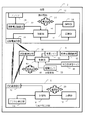
- Example 1 It is a system configuration figure of Example 1 of the present invention.
- Example 1 It is a block diagram of the detailed structure of Example 1 of FIG. It is sectional drawing of the ear
- 3 is a flowchart illustrating functions of an ear wearing unit according to the first embodiment. 3 is a flowchart illustrating functions of the mobile phone according to the first embodiment. It is a flowchart which shows the function of the residence monitor part in Example 1.
- FIG. It is a system configuration
- FIG. 1 is a system configuration diagram of Example 1 according to the embodiment of the present invention.
- the first embodiment constitutes a watch system in the house 2 and is put on an ear that comes in contact with the cartilage around the hole of the ear 4 of the watch target person by being sandwiched between the antiauricle and the tragus and being placed in the concha cavity.
- a part 6 illustrated with a broken line to distinguish it from the ear structure
- a mobile phone 10 of the person to be watched are included.
- the mobile phone 10 exchanges information with the ear wearing unit 6 and the in-house monitor unit 8 by short-range communication.
- the ear wearing unit 6 functions as a headset of the mobile phone 10 by short-range communication with the mobile phone 10, and can make a call even when the mobile phone 10 is kept in a pocket of clothes, for example.
- the ear wearing part 6 also functions as a hearing aid alone.
- the function as a headset and the function as a hearing aid utilize cartilage conduction described later.
- the ear wearing unit 6 further includes a mastication sensor, and detects movement of the tragus or the like or deformation of the external auditory canal due to mastication.
- the ear mounting portion 6 has a ring shape having a hole 6a, and the ear canal entrance is open even when the ear mounting portion 6 is mounted, so that sounds of the outside world can be heard through the hole 6a, and the ear canal has a feeling of obstruction. Allows no comfortable wearing. Further, as described later, by closing the hole 6a with a finger or covering with a palm as necessary, it is possible to obtain an external ear canal closing effect in cartilage conduction and to hear a louder sound.
- the in-housing monitor unit 8 includes a near field communication unit 12 for performing near field communication with the ear wearing unit 6 and the mobile phone 10 and a digital communication unit 14 for performing always-on Internet communication with the outside.
- the control unit 16 controls the entire residential monitor unit 8 including the short-range communication unit 12 and the digital communication unit 14.
- the storage unit 18 stores programs necessary for the control of the control unit 16 and temporarily stores various data related to control and the like.
- the in-housing monitor unit 8 receives the detection result of the mastication movement from the ear wearing unit 6 by short-range communication, and when the mastication movement predicted in daily life is not detected, there is a possibility of an abnormal state. There is a report from the digital communication unit 14 to the monitoring company. In addition, the in-house monitor unit 8 receives information on the presence or absence of the voice of the person being watched over, which is detected by the headset function of the ear wearing unit 6, by short-range communication, and when no sound is detected for a predetermined period of time, or scream When an urgent voice signal is detected, the digital communication unit 14 notifies the monitoring company that there is a possibility of an abnormal state.
- the mobile phone 10 receives the detection result of the mastication movement from the ear wearing unit 6 through near field communication, and registers in advance that there is a possibility of an abnormal state when the mastication movement predicted in daily life is not detected. Calls are automatically made to a mobile phone of a remote family member, etc., and if there is a response, a notification to that effect is made by automatic voice.
- the mobile phone 10 receives information on the presence or absence of the voice of the person being watched over, which is detected by the headset function of the ear wearing unit 6, by short-range communication, and when no voice is detected for a predetermined period of time or an emergency such as a scream
- a sound signal having a characteristic is detected, it is assumed that there is a possibility of an abnormal state, and an automatic call is made to a mobile phone of a remote family member or the like, and if there is a response, a notification to that effect is made.
- the mobile phone 10 automatically calls a mobile phone of a remote family or the like even if a chewing motion predicted in daily life is detected, and if there is a response, there is no abnormality in the automatic voice. Report to that effect. Also, based on detection of the normal voice of the person being watched over, automatic calling is appropriately made to the mobile phone of the remote family or the like, and if there is a response, a notification that there is no abnormality is made by automatic voice. As a result, a remote family member, etc., can regularly watch three meals, have daily conversations expected, or have regular utterances in a preset time zone (daily You can feel safe knowing that you are talking about traditional shopping and daily life.
- the mobile phone 10 is automatically called even if the person being watched over is not intended, and the content of the conversation is heard. This is undesirable from the viewpoint of privacy for the person being watched over even though it is a family, so that only the fact of the presence or absence of voice is reported and the content of the conversation cannot be determined, as will be described later.
- FIG. 2 is a block diagram of the detailed configuration of the first embodiment of the present invention shown in FIG. Portions common to those in FIG. 1 are denoted by the same reference numerals, and description thereof is omitted unless necessary.
- the configuration of the in-resident monitor unit 8 is as shown in FIG. 1, but includes a power supply unit 20 that supplies power to the entire in-house monitor unit 8.
- the power source unit 20 receives power from a household power source in the house 2.
- the mobile phone 10 has a mobile phone function unit 22 as shown in FIG.
- the near field communication unit 26 communicates with the near field communication units 36 and 12 of the ear wearing unit 6 and the dwelling monitor unit 8, respectively.
- the GPS unit 28 detects the position when the person to be watched wearing the ear wearing unit 6 goes out with the mobile phone 10, and if necessary, with a mobile phone or a watch trader such as the above-mentioned remote family Provide location information of the person being watched over by communicating.
- the control unit 30 controls the entire mobile phone 10 including the mobile phone function unit 22, the short-range communication unit 26, and the GPS unit 28.
- the storage unit 32 stores a program necessary for the control of the control unit 30 and temporarily stores various data related to control and the like.
- a power supply unit 34 having a rechargeable storage battery supplies power to the entire mobile phone 10.
- FIG. 2 for the sake of simplicity, illustrations of configurations normally provided in the mobile phone 10 such as a large touch panel type liquid crystal display unit, a microphone, a speaker, a proximity sensor, and an inner camera illustrated in FIG. 1 are omitted.
- the ear wearing unit 6 includes a short-range communication unit 36 that performs short-range communication with the short-range communication unit 26 of the mobile phone 10 and the short-range communication unit 12 of the residential monitor unit 8.
- the mastication sensor 38 detects the movement of the tragus or the like due to the mastication movement of the person to be watched wearing the ear wearing part 6 or the deformation of the external auditory canal, and detects the presence or absence of mastication by the person to be watched.
- the mastication sensor 38 is composed of a strain gauge or a piezoelectric element.
- the control unit 40 transmits the fact to the mobile phone 10 via the short-range communication unit 36 and the short-range communication unit 26.
- the short-range communication unit 36 transmits the short-distance communication unit 26 to the mobile phone 10, and the short-range communication unit The information is transmitted from 36 to the dwelling monitor 8 via the short-range communication unit 12.
- the cartilage conduction vibration source 42 (for example, adopting a piezoelectric bimorph element) of the ear wearing unit 6 vibrates by the voice signal of the communication partner received from the mobile phone 10 by short-range communication, and this vibration comes into contact with the ear wearing unit 6.
- the bone conduction microphone 44 picks up his / her voice by bone conduction and transmits a voice signal of his / her voice to the mobile phone 10 by short-range communication, thereby establishing a conversation. In this way, the ear wearing unit 6 functions as a headset of the mobile phone 10.
- the external air conduction sound microphone 46 vibrates the cartilage conduction vibration source 42 by an audio signal obtained by picking up a live air conduction sound of a nearby conversation partner.
- the ear wearing part 6 functions as a hearing aid alone.
- the control unit 40 also controls the ear wearing unit 6 for the function of the headset and the function of the hearing aid.
- the bone conduction microphone 44 in the headset function also functions as a voice sensor for watching whether or not the person to be watched is making a voice expected in daily life.
- a power supply unit 48 having a rechargeable storage battery supplies power to the entire ear wearing unit 6.
- Cartilage conduction is a phenomenon discovered by the present inventor, and is a phenomenon in which the cartilage surface of the external auditory canal vibrates due to vibration transmitted to the cartilage around the entrance to the external ear canal such as tragus and generates air conduction sound in the external auditory canal. .
- the air conduction sound generated in the ear canal travels further back in the ear canal and reaches the eardrum.
- the main part of the sound heard by cartilage conduction is the sound heard through the tympanic membrane.
- what is heard through the eardrum is not a sound that enters the ear canal from outside the external auditory canal, but a sound that is generated inside the ear canal.
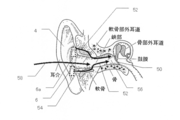
- FIG. 3 is a cross-sectional view of the ear for explaining the above, and shows the relationship between the structure of the ear 4 and the ear mounting portion 6 used in the present invention.
- An arrow 52 illustrates a path through which the vibration of the ear mounting portion 6 that is vibrated by the cartilage conduction vibration source 42 is transmitted to the eardrum 50.
- the vibration generated from the ear mounting portion 6 is first conducted from the contact portion to the cartilage 54 around the ear canal entrance portion.
- the vibration of the cartilage 54 generates air conduction sound from the surface (cartilage part external auditory canal) into the ear canal.
- the air conduction sound travels through the external auditory canal and reaches the eardrum 50 through the bone external auditory canal 56.
- the ear mounting part 6 can be comfortably mounted without a feeling of obstruction of the external auditory canal.
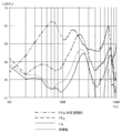
- FIG. 4 is a graph showing an example of actually measured data showing the effect of cartilage conduction.
- the graph of FIG. 4 shows the inside of the ear canal 1 cm from the ear canal entrance when the outer wall surface of the vibrating body vibrated by the cartilage conduction vibration source is brought into contact with at least a part of the ear cartilage around the ear canal entrance without contacting the ear ring. Is shown in relation to the frequency.
- the vertical axis of the graph is the sound pressure (dBSPL), and the horizontal axis is the logarithmic scale frequency (Hz).
- the graph shows the sound pressure in a non-contact state (a state where only the air conduction sound generated from the outer wall surface of the vibrating body can be heard) in a solid line in relation to the contact pressure between the outer wall surface of the vibrating body and the cartilage around the ear canal entrance.
- the sound pressure at a contact pressure of 10 gram is indicated by a broken line
- the sound pressure at a contact pressure of 250 gram is indicated by a one-dot chain line
- the sound pressure when the ear canal is closed by increasing the contact pressure (contact pressure of 500 gram) is indicated by two points. Each is indicated by a chain line.
- the sound pressure is increased by contact at a contact pressure of 10 weight grams from the non-contact state, further increased by increasing the contact pressure to 250 weight grams, and the contact pressure is further increased from this state to 500 weight grams. As a result, the sound pressure further increases.
- the contact pressure in the ear canal at a depth of 1 cm varies by at least 5 dB in the main frequency band (500 Hz to 2500 Hz) of speech. (Refer to the comparison between the slight contact state indicated by the broken line and the contact state indicated by the alternate long and short dash line.)
- the necessary sound can be obtained by transmitting the vibration of the cartilage conduction vibration source 42 to the ear cartilage by contact. It can be seen that pressure is obtained.
- the ear mounting portion 6 can be formed in a ring shape or the like having a hole 6a, and the outside sound can be heard through the hole 6a even during mounting. It can be seen that the device can be worn comfortably without the occlusion of the ear canal.
- the outer ear canal entrance is closed by bringing the outer wall surface of the vibrator into stronger contact with at least a part of the ear cartilage (in the actual measurement of FIG.
- the sound pressure in the ear canal is 1 cm behind the ear canal, compared to the non-contact state. It can be seen that there is an increase of at least 20 dB at 300 Hz to 1800 Hz. This is due to the effect of closing the ear canal. (Refer to the comparison between the non-contact state indicated by the solid line and the state where the ear canal indicated by the two-dot chain line is closed.)
- all the measurements in FIG. 4 are in a state where the output of the cartilage conduction vibration source is not changed. Further, in the state in which the outer wall surface of the vibrating body is brought into contact with at least a part of the ear cartilage around the entrance portion of the ear canal without contact with the ear ring, the measurement in FIG. 4 is performed in a state in which the outer wall surface of the vibrating body is brought into contact with the outside of the tragus. Is going. Moreover, the measurement in the state in which the external auditory canal is closed in FIG. 4 is performed by creating a state in which the external auditory canal is folded back by pressing the tragus more strongly from the outside as described above. .
- Example 1 the outer ear canal closing effect as described above can be realized by closing the hole 6a by pressing the finger 6 against the hole 6a and increasing the contact pressure of the ear mounting portion 6 to the cartilage.
- the effect of closing the ear canal can be obtained by covering the entire ear 4 with a palm instead.
- the measurement graph of FIG. 4 is merely an example, and there are individual differences if you look closely.
- the measurement graph of FIG. 4 is measured in a state where the outer wall surface of the vibrating body is in contact with a small area only on the outer side of the tragus in order to simplify and standardize the phenomenon.
- the increase in sound pressure due to contact also depends on the contact area with the cartilage, and when the outer wall surface of the vibrator is brought into contact with the ear cartilage around the ear canal entrance without contact with the ear ring, it is wider around the ear canal entrance. If the cartilage part is brought into contact, the increase in sound pressure is further increased. Considering the above, the numerical values shown in the measurement graph of FIG.
- the measurement graph of FIG. 4 is based on the result that the tragus is folded back by increasing the contact pressure by pressing the tragus from the outside when closing the ear canal entrance. A similar result can be obtained when it is pushed into and closed.
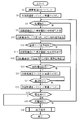
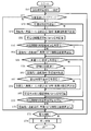
- FIG. 5 is a flowchart showing the function of the control unit 40 of the ear wearing unit 6 in the watching system of the first embodiment.
- the flow starts by removing the ear wearing part 6 connected to a charger (not shown) for charging from the charger.
- the pairing status for short-distance communication with the mobile phone 10 is confirmed in step S2, and if not set, the pairing setting is automatically performed.
- step S4 the external air conduction microphone 46 and the bone conduction microphone 44 are turned on.
- the ear wearing unit 6 functions as a hearing aid, and enters a state of waiting for voice detection of the person being watched over by the bone conduction microphone 44.
- the mastication sensor 38 is always in the on state from the start to the end of the flow and is in the mastication detection standby state.
- step S6 it is checked whether or not the mastication sensor 38 has detected a mastication movement. If there is a detection, the process proceeds to step S8, and a detection signal is transmitted to the mobile phone 10 by short-range communication, and a detection signal is transmitted to the in-house monitoring unit 8 by short-range communication in step S10, and the process proceeds to step S12. To do. On the other hand, if the mastication movement is not detected in step S6, the process proceeds directly to step S12.
- step S12 it is checked whether the bone-conduction microphone 44 has detected the target person's voice. And if there exists detection, it will progress to step S14, and while transmitting the audio
- Steps S12 to S16 are illustrated in a simplified manner. Actually, however, in these steps, bone conduction is performed for a predetermined time (for example, 10 seconds) after the sound is detected by the bone conduction microphone 44. The audio signal from the microphone 44 is continuously transmitted to the mobile phone 10 and the in-house monitor unit 8 in parallel.
- step S12 the transmission is stopped at the predetermined time, and conversely, even if the sound is silenced within the predetermined time, the output transmission of the bone-conduction microphone 44 is continued within the predetermined time.
- step S20 whether or not the person to be watched makes a call operation from the mobile phone 10 and the other party has responded to this, or there is an incoming call to the mobile phone 10 from the outside, and whether or not the person to be watched has made a response operation To check. If either of them is true, the process proceeds to step S22, the external air conduction microphone 46 is turned off and the bone conduction microphone 44 is kept on, and the process proceeds to step S24. As a result, the ear wearing unit 6 functions as a headset of the mobile phone 10, and prevents unnecessary sounds from entering the call from the external air conduction microphone 46.
- step S24 it is checked whether or not the call started in step S20 is terminated by hanging up the telephone.
- the process proceeds to step S26, the external air conduction sound microphone 46 is turned on and the bone conduction microphone 44 is kept on, and the process proceeds to step S28.
- step S24 is repeated to wait for the end of the call. If no outgoing call response or incoming call response is detected in step S20, the process proceeds directly to step S28.
- step S28 it is checked whether or not the storage battery of the power supply unit 48 is exhausted. If the storage battery is not consumed, the process proceeds to step S30, and it is checked whether the ear wearing unit 6 is connected to a charger (not shown) for charging. This step corresponds to the case where the ear mounting portion 6 is detached from the ear 4 and charged even when the storage battery is not consumed.
- step S30 the process proceeds to step S32, and an end process is performed to end the flow. This has the significance of preventing the ear wearing unit 6 from being erroneously maintained in the operating state despite being in a state where it is removed from the ear 4 and cannot perform the watching function.
- step S30 if the charging connection is not detected in step S30, the process returns to step S6. Thereafter, unless the storage battery is consumed or the charging connection is performed, step S6 to step S30 are repeated, and the ear wearing unit 6 The hearing aid function, the watch function, and the headset function of the mobile phone 10 are maintained. In addition, also when the consumption of a storage battery is detected by step S28, it transfers to step S32, complete
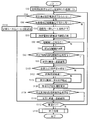
- FIG. 6 is a flowchart illustrating functions of the control unit 30 of the mobile phone 10 according to the first embodiment. Note that the flow of FIG. 6 is illustrated by extracting operations with a focus on functions related to watching, and the mobile phone 10 includes a control unit 30 that is not shown in the flow of FIG. 6 including normal mobile phone functions. There are behaviors.
- the hardware configuration itself of the mobile phone 10 is normal, and the functions extracted in FIG. 6 are installed as software attached to the ear wearing unit 6.
- step S44 the pairing status for near field communication with the ear wearing unit 6 is checked. And if pairing is set, since it can watch over by the mobile telephone 10 cooperated with the ear mounting part 6, it transfers to step S46.
- step S46 it is checked whether or not a new mastication detection signal has been received from the ear wearing unit 6, and if received, the process proceeds to step S48, and the watcher's mobile phone such as a remote family member registered in advance is checked. Automatically send a safety email. Further, in step S48, automatic voice calls are made to a remote family mobile phone registered in advance instead of e-mail by setting in advance, and if there is a response, an automatic voice that informs the safety of the watcher Send. It can also be configured to send both mail and calls.
- mastication detection it is considered that it is basically three times a day and is not complicated, so every time a mastication detection signal is detected, a remote family member is informed of the safety and reassured. If a remote family thinks that such a safe notification is complicated, it can be set in advance to omit step S48.
- step S50 the reception history of the mastication detection signal in the storage unit 32 is updated with date and time information based on new reception, and the GPS signal at that time is also stored, and the process proceeds to step S52.
- step S50 the reception history of the mastication detection signal in the storage unit 32 is updated with date and time information based on new reception, and the GPS signal at that time is also stored, and the process proceeds to step S52.
- the process directly proceeds to step S52.
- step S52 based on the reception history of the storage unit 32, it is checked whether a new mastication detection signal has been received within a predetermined period from the previous reception of the mastication detection signal. If a new mastication detection signal is not received within a predetermined period, the process proceeds to step S54, where an automatic call is made to a mobile phone of a remote family member registered in advance, and if there is a response, there is a possibility of abnormality. An automatic voice to that effect is transmitted and the process proceeds to step S56. In step S54, an automatic voice for notifying the current position of the watcher is further transmitted based on the GPS information at that time. On the other hand, if it can be confirmed in the reception history that a new mastication detection signal has been received within the predetermined period in step S52, the process directly proceeds to step S56.
- step S56 it is checked whether or not an audio signal picked up by the bone-conduction microphone 44 of the ear attachment unit 6 has been received. If a voice signal is received, the process proceeds to step S58, where the received voice is a scream or a rescue request based on the voice identification of the contents of the voice signal (including words etc.), the strength of the voice signal, the tone pattern, etc. Check whether it is urgent. When there is a high possibility that the voice is a scream or rescue request voice (when it is determined that the urgency is high), the process proceeds to step S60, and an automatic call is made to a mobile phone of a remote family member registered in advance. If there is a response, the received voice itself is transferred and the process proceeds to step S62. On the other hand, if it is determined in step S58 that the received voice is a normal conversation voice and not a scream or a rescue request (less urgent), the process directly proceeds to step S62.
- step S62 it is checked whether or not the received audio signal is received in a time zone set in advance based on a regular life pattern (for example, a time zone in which daily shopping or sutra is advocated). Then, if applicable, the process proceeds to step S64, and a mail notifying the safety of the watcher is automatically transmitted to a mobile phone of a remote family registered in advance, and the process proceeds to step S66. On the other hand, if it is determined in step S62 that the received audio signal is not received in a preset time zone, the process directly proceeds to step S66. As in step S48, automatic calling and automatic voice transmission may be performed instead of e-mail, or both may be set to be performed.
- a regular life pattern for example, a time zone in which daily shopping or sutra is advocated.
- step S62 and step S64 when a remote family thinks that such a safe notification is complicated, it can be set in advance so as to omit step S62 and step S64.
- the voice transmitted in step S64 is not a voice signal actually picked up by the bone-conduction microphone 44 but only a fact that a voice signal has been received.
- step S60 the voice of the person being watched over is notified.
- the content of the conversation is unknown and privacy is preserved.
- step S66 the reception history of the audio signal in the storage unit 32 is updated with date and time information based on new reception, and the GPS signal at that time is also stored, and the process proceeds to step S68.
- step S68 the reception history of the audio signal picked up by the bone-conduction microphone 44 is not confirmed in step S56, the process directly proceeds to step S68.
- step S68 based on the reception history of the storage unit 32, it is checked whether or not a new audio signal has been received within a predetermined period from the previous reception of the audio signal. If no new audio signal is received within a predetermined period, the process proceeds to step S70, where an automatic call is made to the previously registered mobile phone of a remote family or the like, and if there is a response, there is a possibility of abnormality. An automatic voice to that effect is transmitted and the process proceeds to step S72. Also in step S70, an automatic voice for notifying the current position of the watcher is transmitted based on the GPS information at that time.
- step S68 when it is confirmed in the reception history that a new audio signal has been received within the predetermined period in step S68, the process directly proceeds to step S72. If the pairing setting with the ear wearing unit 6 is not confirmed in step S44, the process directly proceeds to step S72, and the steps for watching are not executed, and functions as a normal mobile phone.
- step S72 it is checked whether or not the storage battery of the power supply unit 34 is exhausted. If the storage battery is not exhausted, the process returns to step S44. Hereinafter, unless the storage battery is exhausted, step S44 to step S72 are repeated, and the mobile phone 10 responds to various situations in watching. On the other hand, when the consumption of the storage battery is detected in step S72, the process proceeds to step S74, the end process is performed, and the flow is ended.
- FIG. 7 is a flowchart illustrating the function of the control unit 16 of the in-resident monitoring unit 8 according to the first embodiment.
- the flow starts by installing the in-house monitor unit 8 and connecting it to a household power source or by turning on the power source of the in-house monitor unit 8.
- the Internet is constantly connected for communication with the watchmaker.
- the automatic setting is performed, and an automatic test for cooperation such as near field communication with the ear wearing unit 6 is performed, and the process proceeds to step S84.
- step S84 it is checked whether or not the state where the near field communication with the ear wearing unit 6 is possible is changed to the impossible state. This is equivalent to checking whether or not the person being watched over has gone out of the near field communication range. If not, the process proceeds to step S86, and it is checked whether or not the state where the near field communication with the ear wearing unit 6 is impossible is changed to the possible state. This corresponds to checking whether or not the person to be watched returns home and returns to the near field communication range. If applicable, in step S88, automatic mail transmission to the previously registered mobile phone of a remote family or the like is performed to notify that the person to be watched has returned home.
- step S90 automatic short-range communication is performed with the mobile phone 10, and processing for confirming that the short-range communication state has returned to the system configuration state shown in FIG. This is because it is assumed that the mobile phone 10 was also carried by the watching target person and went out of the near field communication area of the in-resident monitor unit 8 while the watching target person was out. If it cannot be confirmed in step S90 that short-distance communication with the mobile phone 10 can be performed, in step S90, the mobile phone such as a contractor or a remote family is notified.
- step S90 cross check and information exchange of the reception history from the ear wearing unit 6 in the storage unit 18 of the in-house monitor unit 8 and the storage unit 32 of the mobile phone 10 are further performed to match the information of both.
- This is mainly due to reception information being lost while the monitoring target person goes out and the in-housing monitor unit 8 cannot receive from the ear wearing unit 6, so that the received information is received from the mobile phone 10.
- in-house monitor unit 8 can prevent inconvenience such as misidentifying that there is no transmission from ear wearing unit 6 for a predetermined time or longer, although transmission is actually performed from ear wearing unit 6. it can.
- the function of matching both information by the cross check of the reception history as described above is that the storage information of the mobile phone 10 is consumed in the residence 2 and the reception information from the ear wearing unit 6 is missing until charging. It is also meaningful as a response to the case.
- step S90 the process proceeds to step S92, and it is checked whether a new mastication detection signal has been received from the ear wearing unit 6. If there is reception, the process proceeds to step S94, the reception history of the mastication detection signal in the storage unit 18 is updated with date information based on the new reception, and the process proceeds to step S96. On the other hand, when the reception of the mastication detection signal cannot be confirmed in step S92, the process directly proceeds to step S96.
- step S96 based on the reception history of the storage unit 18, it is checked whether a new mastication detection signal has been received within a predetermined period from the previous reception of the mastication detection signal. If no new mastication detection signal is received within the predetermined period, the process proceeds to step S98, where an automatic notification that there is a possibility of abnormality is given to the pre-contracted watchmaker, and the process proceeds to step S100. On the other hand, if it can be confirmed from the reception history that a new mastication detection signal has been received within the predetermined period in step S96, the process proceeds directly to step S100 with no abnormality.
- step S100 it is checked whether an audio signal picked up by the bone conduction microphone 44 of the ear mounting unit 6 has been received. If a voice signal is received, the process proceeds to step S102, where the received voice is a scream or a rescue request based on the voice identification of the contents (such as contained words) of the voice signal, the intensity of the voice signal, the tone pattern, etc. Check whether or not. If there is a high possibility that it is a scream or a rescue request voice, the process proceeds to step S104, and the received voice itself is transferred to the watcher and the process proceeds to step S106. On the other hand, when it is determined in step S102 that the received voice is a normal conversation voice and not a scream or a rescue request, the process directly proceeds to step S106.
- step S106 the reception history of the audio signal in the storage unit 18 is updated with date information based on the new reception, and the process proceeds to step S108.
- step S108 the reception history of the audio signal picked up by the bone-conduction microphone 44 is not confirmed in step S100, the process directly proceeds to step S108.
- step S108 based on the reception history of the storage unit 18, it is checked whether a new audio signal has been received within a predetermined period from the previous reception of the audio signal. If no new audio signal is received within the predetermined period, the process proceeds to step S110, where the watcher is automatically notified that there is a possibility of abnormality, and the process proceeds to step S112. On the other hand, when it can be confirmed from the reception history that a new audio signal has been received within the predetermined period in step S108, the process directly proceeds to step S112. When it is detected in step S84 that the short-range communication with the ear wearing unit 6 has been changed to the impossible state, the process proceeds to step S114 and the previously registered remote location is registered.
- Automatic mail transmission to a cellular phone such as a family is performed to notify that the person to be watched has gone out, and the process proceeds to step S112.
- a signal cannot be received from the ear wearing unit 6 and watching cannot be performed
- execution of the watching function is entrusted to the mobile phone 10 carried by the watching target person, and execution of the watching function as the in-house monitoring unit 8 is performed. Absent.
- step S112 it is checked whether or not the power source of the in-resident monitor unit 8 is turned off. Power off includes power interruption due to power failure. If the power is not turned off, the process returns to step S84. Hereinafter, unless the power is turned off, steps S84 to S114 are repeated, and the dwelling monitor unit 8 responds to various situations in watching. On the other hand, when the power-off is detected in step S112, the process proceeds to step S116, the end process is performed, and the flow is ended.
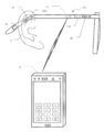
- FIG. 8 is a system configuration diagram of Example 2 according to the embodiment of the present invention.
- the second embodiment also constitutes a monitoring system in the house, and uses a glasses-type ear mounting unit 106. Since other configurations are the same as those of the first embodiment shown in FIGS. 1 and 2, common portions are denoted by the same reference numerals and description thereof is omitted.
- FIG. 8 for the sake of simplicity, illustration of the dwelling 2 and the dwelling monitor unit 8 is omitted, but the configuration is the same as that of the first embodiment of FIGS.
- the common piezoelectric element can be used as the cartilage conduction vibration source, bone conduction microphone, and mastication sensor. It is.
- the piezoelectric bimorph element 142 that is also used as the cartilage conduction vibration source, the bone conduction microphone, and the mastication sensor is provided in a portion where the eyeglass vine rests on the cartilage at the base of the ear 4. With this configuration, the vibration of the piezoelectric bimorph element 142 is transmitted to the cartilage at the base of the ear 4 to cause cartilage conduction.
- the sound by bone conduction is picked up by the piezoelectric bimorph element 142. Furthermore, the movement of the vicinity of the base of the ear 4 by mastication is also detected by the luff element 142. In the combined use, input / output signals of the piezoelectric bimorph element 142 are extracted and separated by signal processing of the control unit 140. At that time, the sound of the person to be watched is picked up by air conduction using the external air conduction microphone 46 originally provided for picking up the voice of the other party for the function of the hearing aid, and the piezoelectric bimorph element This is used as information for extraction and separation of input / output signals at 142.
- the external auditory canal entrance is opened so that the sound of the outside world can be heard, and the comfortable ear mounting part 106 without the occlusion of the external auditory canal can be mounted. Further, if necessary, the ear canal entrance is closed with a finger or the entire ear 4 is covered with a palm, so that the effect of closing the ear canal in cartilage conduction can be obtained and a larger sound can be heard.
- any one of the functions of the cartilage conduction vibration source, the bone conduction microphone, and the mastication sensor may be combined with one piezoelectric bimorph element.
- the cartilage conduction vibration source, the bone conduction microphone, and the mastication sensor may be configured by different optimum elements, respectively, and may be configured to be distributed and arranged at the optimum positions.
- the bone conduction microphone is used to pick up the voice of the person being watched over.
- this may be constituted by an air conduction sound microphone (for example, also used as the external air conduction sound microphone 46). Good.
- a feature of the embodiment disclosed in the present specification is that between the watch detection device and the watch detection device that is mounted on the ear with the cartilage conduction vibration source and the watch detection sensor open and the ear canal entrance is opened.
- a watch system characterized by having a watch notification device that receives watch information from the watch detection sensor by short-range communication. This makes it possible to mount a comfortable watching detection device.
- the watching detection device has an external air conduction sound microphone, and functions as a hearing aid by vibrating the cartilage conduction vibration source by an audio signal picked up by the external air conduction sound microphone. Thereby, it can watch over using the hearing aid used on a daily basis.
- the watch detection device vibrates the cartilage conduction vibration source by an audio signal received from the watch notification device by short-range communication. Thereby, watching can be performed using a device that listens to an audio signal from another device such as a mobile phone.
- the watching detection sensor is a mastication movement sensor.
- the watch detection sensor is an audio sensor.
- the voice sensor is a bone conduction microphone or an air conduction microphone.
- the monitoring notification device notifies the outside when the detection signal cannot be received from the monitoring detection sensor for a predetermined time.
- a plurality of watch notifications that receive watch information from the watch detection device by short-range communication between the watch detection device and the watch detection device.
- a watching system characterized by exchanging watch information received between the plurality of watch notification devices.
- a plurality of watch notifications that receive watch information from the watch detection device by short-range communication between the watch detection device and the watch detection device.
- a monitoring system wherein the plurality of monitoring notification devices perform different notifications based on the monitoring information.
- the plurality of monitoring notification devices include a mobile phone and a notification device installed in a residence.
- the monitoring information is received from the monitoring sensor by short-range communication between the monitoring sensor having an audio sensor and the monitoring sensor.
- the monitoring notification device notifies the outside of the presence or absence of a voice signal picked up by the voice sensor and does not report the contents of the voice signal. This protects the privacy of the person being watched over.
- the monitoring notification device determines the urgency of the audio signal picked up by the audio sensor, and reports the content of the audio signal as an exception when the urgency is high. As a result, for example, a specific report by a live voice can be obtained in a scream or a rescue request.
- the apparatus has a cartilage conduction vibration source and a monitoring sensor, and is mounted on the ear with the ear canal entrance open.
- a monitoring device is provided. This makes it possible to mount a comfortable watching detection device.
- the watching detection device has an external air conduction sound microphone, and functions as a hearing aid by vibrating the cartilage conduction vibration source by an audio signal picked up by the external air conduction sound microphone.
- the cartilage conduction vibration source is vibrated by a voice signal received from the watch notification device by short-range communication, and functions as a device that listens to a voice signal from another device such as a mobile phone. .
- the watching detection sensor is a mastication movement sensor.
- the mastication motion sensor can also be used as the cartilage conduction vibration source.
- the watch detection sensor is an audio sensor. More specifically, the voice sensor is a bone conduction microphone. More specifically, the bone-conduction microphone can also be used as the cartilage conduction vibration source.
- the watching detection sensor includes an air conduction sound microphone for a hearing aid function, and turns off the air conduction sound microphone when the bone conduction microphone is used.
- said voice sensor is an air conduction microphone.
- the acquisition unit of the monitoring information from the audio sensor, and the outside of the presence or absence of the audio signal acquired by the acquisition unit and the content of the audio signal There is provided a watching and reporting device characterized by having a reporting unit that does not report. This protects the privacy of the person being watched over.
- the reporting unit determines the urgency of the audio signal acquired by the acquiring unit, and reports the content of the audio signal as an exception when the urgency is high.
- the present invention can be applied to a watching system, a watching detection device, and a watching notification device.
Landscapes
- Engineering & Computer Science (AREA)
- Physics & Mathematics (AREA)
- Signal Processing (AREA)
- Acoustics & Sound (AREA)
- Computer Networks & Wireless Communication (AREA)
- Health & Medical Sciences (AREA)
- General Health & Medical Sciences (AREA)
- Otolaryngology (AREA)
- General Physics & Mathematics (AREA)
- Neurosurgery (AREA)
- Emergency Management (AREA)
- Business, Economics & Management (AREA)
- Human Computer Interaction (AREA)
- Telephone Function (AREA)
- Alarm Systems (AREA)
- Emergency Alarm Devices (AREA)
- Headphones And Earphones (AREA)
- Details Of Audible-Bandwidth Transducers (AREA)
- Circuit For Audible Band Transducer (AREA)
Abstract
Description
以下では、本明細書中に開示されている種々の実施例の特徴について総括的に述べる。
38、44、46 見守り検知センサ
6、106 見守り検知装置
12、26、36 近距離通信部
8、10 見守り通報装置
46 外部気導音マイク
38 咀嚼運動センサ
44、46 音声センサ
44 骨導マイク
46 気導音マイク
8、10 複数の見守り通報装置
10 携帯電話
8 住居内に設置される通報装置
142 軟骨伝導振動源と兼用される咀嚼運動センサ
142 軟骨伝導振動源と兼用される骨導マイク
Claims (20)
- 軟骨伝導振動源と、見守り検知センサとを有し、外耳道入口を開放した状態で耳に装着されることを特徴とする見守り検知装置。
- 外部気導音マイクを有し、前記外部気導音マイクで拾った音声信号により前記軟骨伝導振動源を振動させることにより補聴器として機能することを特徴とする請求項1記載の見守り検知装置。
- 見守り通報装置との通信が可能な近距離通信部を有し、前記近距離通信部により前記見守り通報装置から受信した音声信号により前記軟骨伝導振動源を振動させることを特徴とする請求項1記載の見守り検知装置。
- 前記見守り検知センサは、咀嚼運動センサであることを特徴とする請求項1記載の見守り検知装置。
- 前記咀嚼運動センサは前記軟骨伝導振動源と兼用されることを特徴とする請求項4記載の見守り検知装置。
- 前記見守り検知センサは、音声センサであることを特徴とする請求項1記載の見守り検知装置。
- 前記音声センサは骨導マイクであることを特徴とする請求項6記載の見守り検知装置。
- 前記骨導マイクは前記軟骨伝導振動源と兼用されることを特徴とする請求項7記載の見守り検知装置。
- 補聴器機能のための外部気導音マイクを有し、前記骨導マイクが使用されるとき前記外部気導音マイクをオフすることを特徴とする請求項7記載の見守り検知装置。
- 請求項1記載の見守り検知装置と、前記見守り検知装置との間の近距離通信により前記見守り検知センサからの見守り情報を受信する見守り通報装置とを有することを特徴とする見守りシステム。
- 前記見守り検知センサは音声センサであり、前記見守り通報装置は、前記音声センサが拾う音声信号の存否を外部に通報するとともに前記音声信号の内容は通報しないことを特徴とする請求項10記載の見守りシステム。
- 前記見守り通報装置は、前記音声センサが拾う音声信号の緊急性を判断し、緊急性が高いときは例外として前記音声信号の内容を通報することを特徴とする請求項11記載の見守りシステム。
- 前記見守り通報装置は、見守り検知センサから所定時間検知信号が受信できないとき外部への通報を行なうことを特徴とする請求項10記載の見守りシステム。
- 前記見守り通報装置は、同一の見守り検知装置から見守り情報を受信する複数の見守り通報装置を含み、前記複数の見守り通報装置間で受信した見守り情報の交換を行なうこと特徴とする請求項10記載の見守りシステム。
- 前記見守り通報装置は、携帯電話であるとともに、前記携帯電話で受信した通話相手の音声信号を近距離通信により前記見守り検知装置に送信し、前記軟骨伝導振動源を振動させることを特徴とする請求項10記載の見守りシステム。
- 見守り検知装置と、前記見守り検知装置との間の近距離通信により前記見守り検知装置から見守り情報を受信する複数の見守り通報装置とを有し、前記複数の見守り通報装置間で受信した見守り情報の交換を行なうこと特徴とする見守りシステム。
- 前記複数の見守り通報装置は前記見守り情報に基づき異なる通報を行なうこと特徴とする請求項16記載の見守りシステム。
- 前記複数の見守り通報装置は、携帯電話および住居内に設置される通報装置を含むことを特徴とする請求項16記載の見守りシステム。
- 音声センサからの見守り情報の取得部と、前記取得部が取得した音声信号の存否を外部に通報するとともに前記音声信号の内容は通報しない通報部とを有することを特徴とする見守り通報装置。
- 前記通報部は、前記取得部が取得した音声信号の緊急性を判断し、緊急性が高いときは例外として前記音声信号の内容を通報することを特徴とする請求項19記載の見守り通報装置。
Priority Applications (5)
| Application Number | Priority Date | Filing Date | Title |
|---|---|---|---|
| CN201580044713.0A CN106664474B (zh) | 2014-08-20 | 2015-07-29 | 看护系统、看护检测装置和看护通知装置 |
| US15/500,575 US10013862B2 (en) | 2014-08-20 | 2015-07-29 | Watching system, watching detection device, and watching notification device |
| EP15834516.5A EP3185581B1 (en) | 2014-08-20 | 2015-07-29 | Watching system, watching detection device, and watching notification device |
| KR1020177004700A KR102001320B1 (ko) | 2014-08-20 | 2015-07-29 | 워칭 시스템, 워칭 검지 장치 및 워칭 통보 장치 |
| US15/993,695 US10380864B2 (en) | 2014-08-20 | 2018-05-31 | Watching system, watching detection device, and watching notification device |
Applications Claiming Priority (2)
| Application Number | Priority Date | Filing Date | Title |
|---|---|---|---|
| JP2014167610A JP6551919B2 (ja) | 2014-08-20 | 2014-08-20 | 見守りシステム、見守り検知装置および見守り通報装置 |
| JP2014-167610 | 2014-08-20 |
Related Child Applications (2)
| Application Number | Title | Priority Date | Filing Date |
|---|---|---|---|
| US15/500,575 A-371-Of-International US10013862B2 (en) | 2014-08-20 | 2015-07-29 | Watching system, watching detection device, and watching notification device |
| US15/993,695 Continuation US10380864B2 (en) | 2014-08-20 | 2018-05-31 | Watching system, watching detection device, and watching notification device |
Publications (1)
| Publication Number | Publication Date |
|---|---|
| WO2016027632A1 true WO2016027632A1 (ja) | 2016-02-25 |
Family
ID=55350578
Family Applications (1)
| Application Number | Title | Priority Date | Filing Date |
|---|---|---|---|
| PCT/JP2015/071490 Ceased WO2016027632A1 (ja) | 2014-08-20 | 2015-07-29 | 見守りシステム、見守り検知装置および見守り通報装置 |
Country Status (7)
| Country | Link |
|---|---|
| US (2) | US10013862B2 (ja) |
| EP (1) | EP3185581B1 (ja) |
| JP (1) | JP6551919B2 (ja) |
| KR (1) | KR102001320B1 (ja) |
| CN (1) | CN106664474B (ja) |
| TW (1) | TWI610274B (ja) |
| WO (1) | WO2016027632A1 (ja) |
Families Citing this family (12)
| Publication number | Priority date | Publication date | Assignee | Title |
|---|---|---|---|---|
| DK3550858T3 (da) * | 2015-12-30 | 2023-06-12 | Gn Hearing As | Et på hovedet bærbart høreapparat |
| KR101772007B1 (ko) * | 2017-02-22 | 2017-08-28 | 주식회사 블루웨일 | 안전감지기능이 구비된 난청 보완 장치 |
| US10757501B2 (en) | 2018-05-01 | 2020-08-25 | Facebook Technologies, Llc | Hybrid audio system for eyewear devices |
| DE102018209822A1 (de) * | 2018-06-18 | 2019-12-19 | Sivantos Pte. Ltd. | Verfahren zur Steuerung der Datenübertragung zwischen zumindest einem Hörgerät und einem Peripheriegerät eines Hörgerätesystems sowie Hörgerät |
| EP3901740A1 (en) * | 2018-10-15 | 2021-10-27 | Orcam Technologies Ltd. | Hearing aid systems and methods |
| US10658995B1 (en) | 2019-01-15 | 2020-05-19 | Facebook Technologies, Llc | Calibration of bone conduction transducer assembly |
| JP7354646B2 (ja) * | 2019-07-24 | 2023-10-03 | 株式会社Jvcケンウッド | 無線機、無線通信システム及び無線通信方法 |
| US11006197B1 (en) * | 2019-10-30 | 2021-05-11 | Facebook Technologies, Llc | Ear-plug device with in-ear cartilage conduction transducer |
| JP7322916B2 (ja) * | 2021-03-25 | 2023-08-08 | カシオ計算機株式会社 | 情報処理方法、情報処理システムおよびプログラム |
| EP4322556A4 (en) * | 2021-05-31 | 2024-10-09 | Samsung Electronics Co., Ltd. | Electronic device including integrated inertial sensor and method for operating same |
| US11678103B2 (en) | 2021-09-14 | 2023-06-13 | Meta Platforms Technologies, Llc | Audio system with tissue transducer driven by air conduction transducer |
| CN116112857A (zh) * | 2023-02-08 | 2023-05-12 | 深圳市冠标科技发展有限公司 | 一种检测方法、装置、电子设备及计算机存储介质 |
Citations (5)
| Publication number | Priority date | Publication date | Assignee | Title |
|---|---|---|---|---|
| JP2003173375A (ja) * | 2001-09-28 | 2003-06-20 | Toshiba Corp | 生活管理端末装置、生活管理方法並びに生活管理システム |
| WO2006028045A1 (ja) * | 2004-09-07 | 2006-03-16 | Temco Japan Co., Ltd. | メガネ型通信装置 |
| JP2010010945A (ja) * | 2008-06-25 | 2010-01-14 | Cosmo Gear Kk | 骨伝導マイク・スピーカ通話装置 |
| JP2011212167A (ja) * | 2010-03-31 | 2011-10-27 | Japan Health Science Foundation | 生体情報入力用トランスデューサ、生体情報発信装置、生体情報監視装置及び生体情報監視システム |
| JP2013235316A (ja) * | 2012-05-07 | 2013-11-21 | Katsuo Hitomi | 独居者向けの安否確認システム |
Family Cites Families (559)
| Publication number | Priority date | Publication date | Assignee | Title |
|---|---|---|---|---|
| US2045404A (en) | 1933-05-24 | 1936-06-23 | Sonotone Corp | Piezoelectric vibrator device |
| JPS6010823B2 (ja) | 1974-07-11 | 1985-03-20 | 東芝タンガロイ株式会社 | ゴルフスパイクの製造法 |
| JPS5194220A (en) | 1975-02-15 | 1976-08-18 | Denkishingo shindohenkansochi | |
| JPS5588497A (en) | 1978-12-25 | 1980-07-04 | Matsushita Electric Ind Co Ltd | Ear receiver |
| JPS5821267Y2 (ja) | 1979-07-16 | 1983-05-06 | 松下電器産業株式会社 | 受話器 |
| JPS5617780A (en) | 1979-07-25 | 1981-02-19 | Mitsubishi Heavy Ind Ltd | Hatch cover device |
| JPS5676003A (en) | 1979-11-28 | 1981-06-23 | Fuji Electric Co Ltd | Measuring device for stroke of breaker |
| JPS5690018U (ja) | 1979-12-14 | 1981-07-18 | ||
| JPS5689086A (en) | 1979-12-20 | 1981-07-20 | Seiko Epson Corp | Display device for digital watch |
| JPS5690018A (en) | 1979-12-21 | 1981-07-21 | Ihara Chem Ind Co Ltd | Preparation of organic bromide |
| US4351166A (en) | 1980-11-10 | 1982-09-28 | Juliette Belin | Ring |
| JPS58182398A (ja) | 1982-04-19 | 1983-10-25 | Takeshi Yoshii | 送受話兼用型電磁式骨伝導・鼓膜振動音マイクロホン |
| JPS60116800A (ja) | 1983-11-29 | 1985-06-24 | Naganoken | 高速電流反転電解による脱脂及び活性化方法 |
| JPS60116800U (ja) | 1984-01-17 | 1985-08-07 | イ−スタンエレクトリツク株式会社 | 補聴器 |
| JPS62208680A (ja) | 1986-03-07 | 1987-09-12 | Murata Mfg Co Ltd | 積層バイモルフ |
| JPS63115728A (ja) | 1986-11-05 | 1988-05-20 | Toyota Motor Corp | ステアリングホイ−ル芯材の製造方法 |
| US4736250A (en) | 1986-11-28 | 1988-04-05 | Tektronix, Inc. | Digital camera frame capture circuit |
| JPS63140753A (ja) | 1986-11-30 | 1988-06-13 | Chuo Denki Kogyo Kk | 多孔型放熱体の製造方法 |
| JPS63115728U (ja) | 1987-01-22 | 1988-07-26 | ||
| JPS63140753U (ja) | 1987-03-06 | 1988-09-16 | ||
| FR2629624B1 (fr) | 1988-04-05 | 1990-11-16 | Framatome Sa | Procede de determination et d'evaluation de la capacite de retour en puissance d'un reacteur nucleaire a eau pressurisee |
| JPH0262199A (ja) | 1988-08-02 | 1990-03-02 | B Shriver Simeon | 骨伝導型音声聴取装置および方法 |
| JPH02182098A (ja) | 1989-01-07 | 1990-07-16 | Hiroshi Osada | ステレオ用ヘッドホン |
| JPH0329424A (ja) | 1989-06-27 | 1991-02-07 | Oki Electric Ind Co Ltd | ハンズフリー電話用エコーキャンセラ回路 |
| JPH03117995A (ja) | 1989-09-29 | 1991-05-20 | Mitsubishi Electric Corp | 色信号輪郭補正装置 |
| JPH03117995U (ja) | 1990-03-14 | 1991-12-05 | ||
| GB9008887D0 (en) | 1990-04-20 | 1990-06-20 | Rothmans Benson & Hedges | Cigarette smoke filter |
| JPH0490298A (ja) | 1990-08-02 | 1992-03-24 | Matsushita Electric Ind Co Ltd | 補聴器 |
| JP3009206B2 (ja) | 1990-11-05 | 2000-02-14 | 株式会社日立製作所 | ビデオカメラ装置 |
| JP3003950B2 (ja) | 1990-12-26 | 2000-01-31 | 多摩川精機株式会社 | エンコーダ用回転ディスク板 |
| JP3235865B2 (ja) | 1991-06-03 | 2001-12-04 | パイオニア株式会社 | イヤースピーカ |
| US5956682A (en) | 1991-06-06 | 1999-09-21 | Lj Laboratories, Llc | Picture frame with associated audio messages and position sensitive or speech recognition device |
| JPH0541297A (ja) | 1991-07-31 | 1993-02-19 | Ishikawajima Harima Heavy Ind Co Ltd | Sor装置の真空排気装置 |
| JP3064055B2 (ja) | 1991-08-29 | 2000-07-12 | 昭和アルミニウム株式会社 | 熱交換器の製造方法 |
| JP2894035B2 (ja) | 1991-09-18 | 1999-05-24 | 日産自動車株式会社 | 能動型騒音制御装置 |
| JPH05183618A (ja) | 1991-12-27 | 1993-07-23 | Sony Corp | 電話機 |
| US5295193A (en) | 1992-01-22 | 1994-03-15 | Hiroshi Ono | Device for picking up bone-conducted sound in external auditory meatus and communication device using the same |
| JP3070222B2 (ja) | 1992-02-21 | 2000-07-31 | 松下電器産業株式会社 | 流量調節装置 |
| JPH05292167A (ja) | 1992-04-13 | 1993-11-05 | Sony Corp | 電話器 |
| US5323468A (en) | 1992-06-30 | 1994-06-21 | Bottesch H Werner | Bone-conductive stereo headphones |
| JP3101842B2 (ja) | 1992-07-06 | 2000-10-23 | アツデン株式会社 | 指向性マイクロホン装置 |
| JPH0739150A (ja) | 1993-07-16 | 1995-02-07 | Nec Field Service Ltd | 電源装置 |
| HU212134B (hu) | 1993-07-27 | 1998-06-29 | László Holakovszky | Szemüveghez rögzített kép-, előnyösen TV-kép-megjelenítő berendezés |
| JP2698320B2 (ja) | 1993-08-31 | 1998-01-19 | 日本電信電話株式会社 | 常装着型入力システム、常装着型意図伝達システム、常装着型音楽用キーボードシステム及び常装着型点字入出力システム |
| JPH07107146A (ja) | 1993-10-05 | 1995-04-21 | Mitsubishi Electric Corp | 骨伝導イヤホンマイクを用いたコードレス電話装置 |
| JPH07131268A (ja) | 1993-10-29 | 1995-05-19 | Casio Comput Co Ltd | 電話機 |
| JPH0739150U (ja) | 1993-12-14 | 1995-07-14 | アツデン株式会社 | 携帯用電話機 |
| JP3907215B2 (ja) | 1994-01-18 | 2007-04-18 | 富士通テン株式会社 | 騒音制御装置 |
| JP3003950U (ja) | 1994-05-09 | 1994-11-01 | 株式会社京浜特殊印刷 | 外国語学習用増幅器 |
| CN2198618Y (zh) | 1994-05-19 | 1995-05-24 | 刘瓒澄 | 立体电视眼镜 |
| KR970008927B1 (en) | 1994-06-21 | 1997-05-30 | Lg Electronics Inc | The power saving apparatus of cellular phone |
| JPH0833026A (ja) | 1994-07-15 | 1996-02-02 | Nitsuko Corp | 無線機器におけるバッテリー支持装置 |
| JPH0879338A (ja) | 1994-08-30 | 1996-03-22 | Sanyo Electric Co Ltd | 携帯電話装置 |
| JP3009206U (ja) | 1994-09-19 | 1995-04-04 | リオン電子株式会社 | 圧電駆動型搬送装置 |
| JPH0890986A (ja) | 1994-09-28 | 1996-04-09 | Pilot Corp:The | 筆記具 |
| JPH08102780A (ja) | 1994-09-30 | 1996-04-16 | Nippon Telegr & Teleph Corp <Ntt> | 電話機用補聴器 |
| JPH08111703A (ja) | 1994-10-07 | 1996-04-30 | Matsushita Electric Ind Co Ltd | 移動無線電話装置 |
| JP3418808B2 (ja) | 1995-02-27 | 2003-06-23 | 富士通株式会社 | 移動通信用端末機 |
| JPH08242273A (ja) | 1995-03-02 | 1996-09-17 | Tdk Corp | 着信バイブレータ |
| JPH08256080A (ja) | 1995-03-16 | 1996-10-01 | Sharp Corp | 携帯情報機器 |
| JPH0923256A (ja) | 1995-07-07 | 1997-01-21 | Oki Electric Ind Co Ltd | 電話機構造 |
| KR0161916B1 (ko) | 1995-07-14 | 1998-12-01 | 구자홍 | 위성방송 수신시스템의 캐리어 주파수오차 보정회로 |
| CN1141856A (zh) | 1995-08-02 | 1997-02-05 | 楚树湘 | 传真雕塑方法 |
| JP3050147B2 (ja) | 1995-12-20 | 2000-06-12 | 東ソー株式会社 | 空気分離用吸着剤、その製造法並びにそれを用いた空気分離方法 |
| US5687244A (en) | 1996-03-28 | 1997-11-11 | Stanton Magnetics, Inc. | Bone conduction speaker and mounting system |
| JP2888287B2 (ja) | 1996-07-25 | 1999-05-10 | 日本電気株式会社 | 電話機 |
| WO1998005148A1 (en) | 1996-07-29 | 1998-02-05 | Nihon Velbon Seiki Kogyo Kabushiki Kaisha | Wristwatchlike telephone set |
| KR100229033B1 (ko) | 1996-09-24 | 1999-11-01 | 윤종용 | 비휘발성 메모리에 기록시 시스템의 절전 장치 및 방법 |
| TW353164B (en) | 1996-10-04 | 1999-02-21 | Compaq Computer Corp | Computer system wake-up mechanism |
| JP3172827B2 (ja) | 1996-10-28 | 2001-06-04 | 正雄 遠藤 | 難聴者のための音認識方法及び装置 |
| KR19980022845U (ko) | 1996-10-29 | 1998-07-25 | 배순훈 | 진공청소기의 연장관 연결구조 |
| JPH10200608A (ja) | 1997-01-10 | 1998-07-31 | Shuichi Osawa | 携帯電話機 |
| KR19980063410A (ko) * | 1997-08-19 | 1998-10-07 | 양승택 | 골도 및 기도 청각 겸용의 수화갑이 구비된 전화기 |
| JPH11112672A (ja) | 1997-09-30 | 1999-04-23 | Mitsubishi Electric Corp | 多地点通話装置 |
| JPH11163980A (ja) | 1997-12-01 | 1999-06-18 | Daisan Kikaku Kk | 携帯電話用の着信感知装身具 |
| JP2589555Y2 (ja) | 1997-12-04 | 1999-01-27 | 日本電気株式会社 | 電池収納構造 |
| JP3050147U (ja) | 1997-12-24 | 1998-06-30 | 嘉正 平田 | 難聴者用簡易型携帯電話機 |
| JP3298578B2 (ja) | 1998-03-18 | 2002-07-02 | 日本電信電話株式会社 | 装着型コマンド入力装置 |
| US6912287B1 (en) | 1998-03-18 | 2005-06-28 | Nippon Telegraph And Telephone Corporation | Wearable communication device |
| JP3067762B2 (ja) | 1998-03-18 | 2000-07-24 | 日本電信電話株式会社 | 装着型通信装置 |
| JPH11298595A (ja) | 1998-04-10 | 1999-10-29 | Mitsubishi Electric Corp | 通信装置 |
| JP3207158B2 (ja) | 1998-05-11 | 2001-09-10 | 株式会社テムコジャパン | 骨導スピ−カ−とマイクロホンを備えたヘッドセット |
| JPH11352138A (ja) | 1998-06-04 | 1999-12-24 | Seiko Instruments Inc | 磁気力顕微鏡 |
| JP2000013294A (ja) | 1998-06-24 | 2000-01-14 | Nippon Telegr & Teleph Corp <Ntt> | 無線送受話器 |
| JP3160714B2 (ja) | 1998-07-08 | 2001-04-25 | 株式会社シコー技研 | 携帯無線通信機 |
| JP3144392B2 (ja) | 1998-09-18 | 2001-03-12 | 日本電気株式会社 | 半導体集積回路の設計方法及び設計装置 |
| US6463157B1 (en) | 1998-10-06 | 2002-10-08 | Analytical Engineering, Inc. | Bone conduction speaker and microphone |
| US6950126B1 (en) | 1998-11-19 | 2005-09-27 | Nikon Corporation | Camera capable of communicating with other communication device |
| JP4281182B2 (ja) | 1998-11-19 | 2009-06-17 | 株式会社ニコン | 通信機能付きカメラ |
| JP3064055U (ja) | 1999-02-08 | 1999-12-14 | 照美 森屋 | 受話口と送話口の距離が適切な細型携帯電話 |
| JP3537128B2 (ja) | 1999-04-01 | 2004-06-14 | 日本電信電話株式会社 | ヘッドホン |
| JP2000324217A (ja) | 1999-05-07 | 2000-11-24 | Ntt Docomo Inc | 携帯機器における音情報伝達装置および携帯機器 |
| JP4142836B2 (ja) | 1999-10-29 | 2008-09-03 | 株式会社インターナショナル インテリジェント インフォメーション | ペンフォンpda |
| JP3750910B2 (ja) | 1999-12-13 | 2006-03-01 | セイコーインスツル株式会社 | 情報処理装置及び情報処理方法 |
| JP3541765B2 (ja) | 1999-12-21 | 2004-07-14 | 日本電気株式会社 | テレビ電話装置 |
| CA2396260C (en) | 2000-01-07 | 2007-09-11 | Lewis Athanas | Mechanical-to-acoustical transformer and multi-media flat film speaker |
| JP3070222U (ja) | 2000-01-11 | 2000-07-28 | 勲 伊藤 | 骨伝導受話機 |
| JP2001287183A (ja) | 2000-01-31 | 2001-10-16 | Matsushita Electric Works Ltd | 自動搬送ロボット |
| JP2001268211A (ja) | 2000-03-21 | 2001-09-28 | Xanavi Informatics Corp | 電話機用ハンズフリー装置 |
| JP3556151B2 (ja) | 2000-05-09 | 2004-08-18 | 株式会社テムコジャパン | 骨伝導スピーカを用いた送受話装置 |
| JP2001333161A (ja) | 2000-05-18 | 2001-11-30 | Nec Corp | 携帯端末 |
| JP2001339504A (ja) | 2000-05-26 | 2001-12-07 | Sharp Corp | 無線通信機 |
| JP2001352395A (ja) | 2000-06-07 | 2001-12-21 | Sony Corp | 携帯端末装置 |
| CN1326022C (zh) | 2000-06-12 | 2007-07-11 | 美国联合包裹服务公司 | 实时跟踪包裹的系统、方法、和设备 |
| WO2001099392A1 (en) | 2000-06-21 | 2001-12-27 | Seiko Epson Corporation | Mobile telephone and radio communication device cooperatively processing incoming call |
| JP2002084575A (ja) | 2000-06-21 | 2002-03-22 | Seiko Epson Corp | 装着型無線通信装置、携帯電話装置、それらの制御方法、無線通信システムの制御方法、制御プログラムおよび記録媒体 |
| JP2002016720A (ja) | 2000-06-29 | 2002-01-18 | Matsushita Electric Ind Co Ltd | 情報通信装置 |
| JP3745602B2 (ja) | 2000-07-27 | 2006-02-15 | インターナショナル・ビジネス・マシーンズ・コーポレーション | 身体セット型スピーカ装置 |
| JP2002036158A (ja) | 2000-07-27 | 2002-02-05 | Yamaha Motor Co Ltd | 自律機能を有する電子機器 |
| US20040105566A1 (en) | 2000-07-27 | 2004-06-03 | International Business Machines Corporation | Body set type speaker unit |
| JP2002041411A (ja) | 2000-07-28 | 2002-02-08 | Nippon Telegr & Teleph Corp <Ntt> | テキスト読み上げロボット、その制御方法及びテキスト読み上げロボット制御プログラムを記録した記録媒体 |
| JP4059618B2 (ja) | 2000-07-31 | 2008-03-12 | 株式会社ケンウッド | 通信端末 |
| JP3949912B2 (ja) | 2000-08-08 | 2007-07-25 | 株式会社エヌ・ティ・ティ・ドコモ | 携帯型電子機器、電子機器、振動発生器、振動による報知方法および報知制御方法 |
| WO2002021881A1 (en) | 2000-09-04 | 2002-03-14 | Applied Electronics Laboratories, Inc. | Display window having voice input/output function |
| JP3831190B2 (ja) | 2000-10-02 | 2006-10-11 | 株式会社エヌ・ティ・ティ・ドコモ | アクチュエータ支持装置及び該アクチュエータ支持装置を備えた身体装着型送受話装置 |
| JP3312902B2 (ja) | 2000-11-24 | 2002-08-12 | 株式会社テムコジャパン | 難聴者用携帯電話機アタッチメント |
| JP2002171321A (ja) | 2000-11-30 | 2002-06-14 | Toshiba Corp | 移動無線端末 |
| JP2002223475A (ja) | 2001-01-25 | 2002-08-09 | Nec Telecom Syst Ltd | 携帯通信端末,腕時計および着信方式ならびに着信方法 |
| TW510139B (en) | 2001-01-26 | 2002-11-11 | Kirk Acoustics As | An electroacoustic transducer and a coil and a magnet circuit therefor |
| JP3404384B2 (ja) | 2001-02-09 | 2003-05-06 | 太平洋セメント株式会社 | 圧電トランスインバータ |
| JP2002262377A (ja) | 2001-02-28 | 2002-09-13 | Taiyo Yuden Co Ltd | 骨導ピックアップ素子及びそのユニット |
| US7616771B2 (en) | 2001-04-27 | 2009-11-10 | Virginia Commonwealth University | Acoustic coupler for skin contact hearing enhancement devices |
| JP3532535B2 (ja) | 2001-05-31 | 2004-05-31 | 株式会社テムコジャパン | 送受話装置 |
| JP2002368839A (ja) | 2001-06-06 | 2002-12-20 | Matsushita Electric Ind Co Ltd | 電話機及び該電話機の音声信号周波数補正方法 |
| JP3763570B2 (ja) | 2001-06-28 | 2006-04-05 | 松下電器産業株式会社 | スピーカシステム、携帯端末装置および電子機器 |
| US6950685B2 (en) | 2001-07-05 | 2005-09-27 | Eta Sa Manufacture Horlogère Suisse | Electronic instrument intended to be worn on the wrist and including, in particular, an antenna for receiving and/or transmitting radio-frequency signals |
| JP2003101625A (ja) | 2001-07-05 | 2003-04-04 | Mieko Tsuyusaki | 携帯電話装置及び電話装置 |
| JP2003032343A (ja) | 2001-07-17 | 2003-01-31 | Mitsubishi Electric Corp | 携帯電話機 |
| JP2003032768A (ja) | 2001-07-19 | 2003-01-31 | Matsushita Electric Ind Co Ltd | ヘッドホン |
| JP3699018B2 (ja) | 2001-07-25 | 2005-09-28 | 埼玉日本電気株式会社 | 電話機の自動音量調整装置 |
| JP3834494B2 (ja) | 2001-09-19 | 2006-10-18 | 株式会社ケンウッド | 圧電スピーカ装置 |
| JP2003103220A (ja) | 2001-09-28 | 2003-04-08 | Nec Tokin Corp | 生体伝導アクチュエータ |
| JP2003174495A (ja) | 2001-09-28 | 2003-06-20 | Nec Corp | 折り畳み式携帯情報端末 |
| JP2003111175A (ja) | 2001-10-01 | 2003-04-11 | Yukio Masuda | 送受音装置 |
| JP2003125473A (ja) | 2001-10-10 | 2003-04-25 | Nec Tokin Corp | 筐体振動圧電アクチュエータ及び携帯用電子装置 |
| JP4313560B2 (ja) | 2001-10-31 | 2009-08-12 | パナソニック株式会社 | 携帯電話 |
| JP3678694B2 (ja) | 2001-11-02 | 2005-08-03 | Necビューテクノロジー株式会社 | 対話型端末装置、その通話制御方法、およびそのプログラム |
| JP2003145048A (ja) | 2001-11-16 | 2003-05-20 | Nec Tokin Corp | 骨伝導振動アクチュエータ及び携帯用電子装置 |
| JP2003169115A (ja) | 2001-11-29 | 2003-06-13 | Kyocera Corp | 折り畳み式携帯電話機 |
| US6639987B2 (en) | 2001-12-11 | 2003-10-28 | Motorola, Inc. | Communication device with active equalization and method therefor |
| JP2003188985A (ja) | 2001-12-20 | 2003-07-04 | Matsushita Electric Ind Co Ltd | ワイヤレスヘッドセット、これを用いたヘルメット、インターネット電話システム、車両用ハンズフリーシステム、通信システム、クレジット処理システムおよびキャッシュサービスシステム |
| JP4202640B2 (ja) | 2001-12-25 | 2008-12-24 | 株式会社東芝 | 短距離無線通信用ヘッドセット、これを用いたコミュニケーションシステム、および短距離無線通信における音響処理方法 |
| US20030119566A1 (en) | 2001-12-26 | 2003-06-26 | E-Lead Electronic Co., Ltd. | Hand-free device equipped with expansion function modules |
| JP2003211087A (ja) | 2002-01-22 | 2003-07-29 | Nec Tokin Corp | 振動アクチュエータ及びディスプレイ装置 |
| JP2003218989A (ja) | 2002-01-24 | 2003-07-31 | Fdk Corp | 着信装置 |
| US20030174856A1 (en) | 2002-01-25 | 2003-09-18 | Leif Johannsen | Flexible diaphragm with integrated coil |
| ATE414394T1 (de) | 2002-01-25 | 2008-11-15 | Sonion Horsens As | Flexible membran mit integrierter spule |
| JP4203246B2 (ja) | 2002-03-14 | 2008-12-24 | 京セラ株式会社 | 携帯通信装置 |
| JP2003274470A (ja) | 2002-03-19 | 2003-09-26 | Denso Corp | 骨伝導音声振動検出素子、骨伝導音声振動検出素子の製造方法および音声認識システム |
| GB0207732D0 (en) | 2002-04-03 | 2002-05-15 | Ttpcomm Ltd | Wireless communication terminals |
| JP2003300015A (ja) | 2002-04-05 | 2003-10-21 | Nec Tokin Corp | 振動アクチュエータの駆動方法、及び携帯機器 |
| JP2003319022A (ja) | 2002-04-26 | 2003-11-07 | Sanyo Electric Co Ltd | 携帯電話装置 |
| US7657224B2 (en) | 2002-05-06 | 2010-02-02 | Syncronation, Inc. | Localized audio networks and associated digital accessories |
| JP2003348208A (ja) | 2002-05-29 | 2003-12-05 | Temuko Japan:Kk | 骨伝導スピーカを備えた携帯電話機 |
| JP3090729U (ja) | 2002-06-13 | 2002-12-26 | 蕃夫 鈴木 | 筆記用ペン型セパレート送受話器 |
| JP3535143B2 (ja) | 2002-07-01 | 2004-06-07 | 日立マクセル株式会社 | 耳装着型の音情報伝達器 |
| EP1525526A1 (en) | 2002-07-25 | 2005-04-27 | Sonion Horsens A/S | Mobile handset and assembly having multi-loudspeaker system |
| BR0312909A (pt) | 2002-07-26 | 2005-07-12 | Oakley Inc | Interfaces áudio sem fios, portáveis, sistemas de interfaces áudio, óculos, armações oculares e dispositivos áudio interativos e métodos de recebimento de chamadas telefônicas, de manipulação de sinal numa rede sem fios e de navegação em menus |
| JP3985094B2 (ja) | 2002-07-30 | 2007-10-03 | 透 加藤 | 骨導スピーカ装置及び通信システム |
| JP3937982B2 (ja) | 2002-08-29 | 2007-06-27 | ソニー株式会社 | 入出力装置および入出力装置を有する電子機器 |
| KR100619215B1 (ko) | 2002-08-30 | 2006-09-06 | 아사히 가세이 가부시키가이샤 | 마이크로폰, 커뮤니케이션 인터페이스 시스템 |
| JP3889342B2 (ja) | 2002-10-03 | 2007-03-07 | 日本電信電話株式会社 | 装着型通信装置 |
| WO2004034734A1 (ja) | 2002-10-08 | 2004-04-22 | Nec Corporation | アレイ装置および携帯端末 |
| JP3875178B2 (ja) | 2002-11-05 | 2007-01-31 | 日本電信電話株式会社 | ヘッドホン装置 |
| JP4244130B2 (ja) | 2002-11-07 | 2009-03-25 | ソニー・エリクソン・モバイルコミュニケーションズ株式会社 | 携帯端末システム及び携帯端末装置 |
| JP4712294B2 (ja) | 2002-11-08 | 2011-06-29 | 株式会社半導体エネルギー研究所 | 表示装置 |
| SG143934A1 (en) | 2002-11-08 | 2008-07-29 | Semiconductor Energy Lab | Display appliance |
| JP2004173018A (ja) | 2002-11-20 | 2004-06-17 | Toshiba Life Engineering Kk | ヘルメット用通信装置 |
| JP2004187031A (ja) | 2002-12-04 | 2004-07-02 | Temuko Japan:Kk | 骨伝導スピーカーを用いた携帯電話機 |
| JP2004190699A (ja) | 2002-12-06 | 2004-07-08 | Sony Corp | クリップおよびクリップのクランプ方法 |
| CN2575916Y (zh) | 2002-12-13 | 2003-09-24 | 深圳市天霆实业发展有限公司 | 骨导和机导兼容的听筒及其电话机 |
| JP2004205839A (ja) | 2002-12-25 | 2004-07-22 | Fuji Iryoki:Kk | 補聴器具 |
| JP4069294B2 (ja) | 2002-12-26 | 2008-04-02 | Tdk株式会社 | イヤフォン、音声伝達装置 |
| JP2004266321A (ja) | 2003-01-22 | 2004-09-24 | Hitachi Maxell Ltd | 耳装着型の通話装置 |
| JP2004233316A (ja) | 2003-02-03 | 2004-08-19 | Matsushita Electric Ind Co Ltd | 無線通信機能付き時計 |
| JP2004252626A (ja) | 2003-02-19 | 2004-09-09 | Tokyo Shinyu:Kk | 情報端末装置へのメッセージ伝達方法 |
| US7409234B2 (en) | 2003-03-07 | 2008-08-05 | Cardo Systems, Inc. | Wireless communication headset with exchangeable attachments |
| JP4121398B2 (ja) | 2003-03-10 | 2008-07-23 | ソフトバンクモバイル株式会社 | 携帯電話機 |
| JP2004289443A (ja) | 2003-03-20 | 2004-10-14 | Tdk Corp | 振動装置及びこれを用いた携帯用電話 |
| US7098776B2 (en) | 2003-04-16 | 2006-08-29 | Massachusetts Institute Of Technology | Methods and apparatus for vibrotactile communication |
| JP2004357198A (ja) | 2003-05-30 | 2004-12-16 | Sharp Corp | イヤホン |
| KR100548357B1 (ko) | 2003-06-23 | 2006-02-02 | 엘지전자 주식회사 | 휴대단말기의 수신신호 증폭레벨 자동제어장치 및 방법 |
| JP2005020234A (ja) | 2003-06-25 | 2005-01-20 | Nec Commun Syst Ltd | 携帯電話機 |
| US7442164B2 (en) | 2003-07-23 | 2008-10-28 | Med-El Elektro-Medizinische Gerate Gesellschaft M.B.H. | Totally implantable hearing prosthesis |
| JP4380246B2 (ja) | 2003-08-22 | 2009-12-09 | パイオニア株式会社 | イヤホン |
| JP2005080135A (ja) | 2003-09-02 | 2005-03-24 | Toshiba Corp | 骨伝導スピーカ内蔵パッド |
| WO2005025265A1 (ja) | 2003-09-02 | 2005-03-17 | Toshiba Life-Engineering Corporation | 骨伝導スピーカ装置 |
| GB0321617D0 (en) | 2003-09-10 | 2003-10-15 | New Transducers Ltd | Audio apparatus |
| US7257372B2 (en) * | 2003-09-30 | 2007-08-14 | Sony Ericsson Mobile Communications Ab | Bluetooth enabled hearing aid |
| JP2005142729A (ja) | 2003-11-05 | 2005-06-02 | Casio Comput Co Ltd | 腕時計型通信装置 |
| JP4542328B2 (ja) | 2003-11-06 | 2010-09-15 | 京セラ株式会社 | 折り畳み式携帯端末機 |
| JP2005151292A (ja) | 2003-11-18 | 2005-06-09 | Tdk Corp | 骨伝導スピーカ及びこれを用いた眼鏡 |
| JP4272040B2 (ja) | 2003-11-28 | 2009-06-03 | 京セラ株式会社 | 携帯通信端末機 |
| JP3958739B2 (ja) | 2003-12-12 | 2007-08-15 | Necトーキン株式会社 | 音響振動発生素子 |
| JP3965383B2 (ja) | 2003-12-17 | 2007-08-29 | 松下電器産業株式会社 | 携帯端末装置 |
| US7079876B2 (en) | 2003-12-23 | 2006-07-18 | Isaac Levy | Wireless telephone headset built into eyeglasses |
| CN1810062A (zh) | 2003-12-26 | 2006-07-26 | 株式会社坦姆科日本 | 使用骨传导扬声器的声学装置 |
| CN1843019A (zh) | 2004-01-16 | 2006-10-04 | 株式会社坦姆科日本 | 使用骨传导装置的携带式电话机 |
| US7512425B2 (en) | 2004-01-16 | 2009-03-31 | Temco Japan Co., Ltd. | Portable telephone using bone conduction device |
| JP2005223717A (ja) | 2004-02-06 | 2005-08-18 | Sharp Corp | オーディオアンプ |
| JP2005229324A (ja) | 2004-02-13 | 2005-08-25 | Hiroshi Fukamizu | 骨伝導スピーカ |
| US7443283B2 (en) | 2004-02-19 | 2008-10-28 | Massachusetts Institute Of Technology | Methods and apparatus for connecting an intimate group by exchanging awareness cues and text, voice instant messages, and two-way voice communications |
| US7499686B2 (en) | 2004-02-24 | 2009-03-03 | Microsoft Corporation | Method and apparatus for multi-sensory speech enhancement on a mobile device |
| KR101100003B1 (ko) | 2004-03-09 | 2011-12-28 | 호야 가부시키가이샤 | 마스크 블랭크 생산 시스템 |
| WO2005091670A1 (ja) | 2004-03-19 | 2005-09-29 | Temco Japan Co., Ltd. | 骨伝導デバイスユニット並びにそれを用いた携帯電話機及びヘッドセット |
| JPWO2005096664A1 (ja) | 2004-03-31 | 2008-02-21 | 株式会社テムコジャパン | ハイブリッドスピーカ及びハイブリッドスピーカユニット |
| JP4231525B2 (ja) | 2004-03-31 | 2009-03-04 | 株式会社テムコジャパン | 骨伝導スピーカを用いた通話装置 |
| JP4073890B2 (ja) | 2004-04-22 | 2008-04-09 | シャープ株式会社 | 薄膜回路基板、及びそれを備えた圧電式スピーカ装置及び表示装置並びに音源内蔵型表示装置 |
| US8526646B2 (en) | 2004-05-10 | 2013-09-03 | Peter V. Boesen | Communication device |
| JP2005328125A (ja) | 2004-05-12 | 2005-11-24 | Nec Tokin Corp | イヤフォン |
| JP2005340927A (ja) | 2004-05-24 | 2005-12-08 | Toyota Industries Corp | 自己発電機能付き携帯型ラジオ受信機 |
| JP2005348193A (ja) | 2004-06-04 | 2005-12-15 | Nec Tokin Corp | 受話器 |
| JP2005352024A (ja) | 2004-06-09 | 2005-12-22 | Murata Mfg Co Ltd | 眼鏡型インタフェース装置及びセキュリティシステム |
| US20050276164A1 (en) | 2004-06-12 | 2005-12-15 | Scott Amron | Watch adapted to rotate a displayed image so as to appear in a substantially constant upright orientation |
| JP2006005625A (ja) | 2004-06-17 | 2006-01-05 | Nec Tokin Corp | 音響振動発生装置 |
| JP4126291B2 (ja) | 2004-06-23 | 2008-07-30 | 三菱重工業株式会社 | ロボットの制御プログラム更新方法及び該システム |
| JP2006011591A (ja) | 2004-06-23 | 2006-01-12 | Denso Corp | 個人認証システム |
| JP2006007919A (ja) | 2004-06-24 | 2006-01-12 | Mazda Motor Corp | 車両用操作ユニット |
| US7555136B2 (en) | 2004-06-25 | 2009-06-30 | Victorion Technology Co., Ltd. | Nasal bone conduction wireless communication transmitting device |
| JP2006019812A (ja) | 2004-06-30 | 2006-01-19 | Panasonic Mobile Communications Co Ltd | 携帯電話機及び携帯電話機の筐体成型方法 |
| CN100596189C (zh) | 2004-07-08 | 2010-03-24 | 松下电器产业株式会社 | 移动终端装置 |
| JP2006021133A (ja) | 2004-07-08 | 2006-01-26 | Magnetec Japan Ltd | 安全型バーマグネット及びその組立て方法 |
| TWI241831B (en) | 2004-07-28 | 2005-10-11 | Dbtel Inc | Caller identification device and method thereof |
| US20070297637A1 (en) | 2004-07-30 | 2007-12-27 | Matsushita Electric Industrial Co., Ltd. | Loudspeaker System, Mobile Terminal Device, an Electronic Device |
| JP2006050056A (ja) | 2004-08-02 | 2006-02-16 | Matsushita Electric Ind Co Ltd | 折り畳み式携帯無線機 |
| JP2006051300A (ja) | 2004-08-09 | 2006-02-23 | Tadao Sato | 生体血流の観察方法 |
| JP2006066972A (ja) | 2004-08-24 | 2006-03-09 | Nec Tokin Corp | スピーカ装置 |
| JP2006067049A (ja) | 2004-08-25 | 2006-03-09 | Nec Tokin Corp | 複合型スピーカ |
| JP2008511217A (ja) | 2004-08-27 | 2008-04-10 | ビクトリオン テクノロジー カンパニー リミテッド | 鼻骨伝導式無線通信伝送装置 |
| CN1791283B (zh) | 2004-12-16 | 2010-06-23 | 致胜科技股份有限公司 | 鼻骨传导助听装置 |
| KR100640891B1 (ko) | 2004-09-02 | 2006-11-02 | 엘지전자 주식회사 | 무선 tv 파워 on/off 장치 및 방법 |
| JP2006074671A (ja) | 2004-09-06 | 2006-03-16 | Taiyo Yuden Co Ltd | ヘッドセット |
| JP2006086581A (ja) | 2004-09-14 | 2006-03-30 | Nec Tokin Corp | 無線通信機能付ヘッドセット、無線通信システム及びコンピュータプログラム |
| JP4535819B2 (ja) | 2004-09-24 | 2010-09-01 | Necアクセステクニカ株式会社 | 駆動回路および該駆動回路を備える携帯機器 |
| JP2006109326A (ja) | 2004-10-08 | 2006-04-20 | Nec Corp | 携帯端末のセキュリティシステムおよびそのセキュリティ方法 |
| US7283850B2 (en) | 2004-10-12 | 2007-10-16 | Microsoft Corporation | Method and apparatus for multi-sensory speech enhancement on a mobile device |
| JP2006115060A (ja) | 2004-10-13 | 2006-04-27 | Makitekku:Kk | 耳挿入型イヤホン |
| US7522065B2 (en) | 2004-10-15 | 2009-04-21 | Microsoft Corporation | Method and apparatus for proximity sensing in a portable electronic device |
| JP4267554B2 (ja) | 2004-10-29 | 2009-05-27 | ホシデン株式会社 | 電子機器の表示部構造及びこれを備えた電子機器 |
| JP4462011B2 (ja) | 2004-11-01 | 2010-05-12 | 日本電気株式会社 | Tv機能付き携帯端末装置およびtvアンテナ兼入力ペン |
| JP4541111B2 (ja) | 2004-11-17 | 2010-09-08 | Necトーキン株式会社 | 骨伝導スピーカの使用方法及び骨伝導受話装置の使用方法 |
| JP4188304B2 (ja) | 2004-11-26 | 2008-11-26 | ホシデン株式会社 | 圧電アクチュエータ、フラットパネルスピーカ |
| JP2006157318A (ja) | 2004-11-29 | 2006-06-15 | Nec Tokin Corp | 骨伝導スピーカーユニット |
| JP2006155734A (ja) | 2004-11-29 | 2006-06-15 | Kyocera Corp | 携帯機器及び携帯機器セット並びにそのディスクドライブ装置の保護方法 |
| CN1617632A (zh) | 2004-11-30 | 2005-05-18 | 陈奚平 | 头戴式音响装置以及一种声道再现方法 |
| JP2006165702A (ja) | 2004-12-02 | 2006-06-22 | Taiyo Yuden Co Ltd | 圧電発音体及び電子機器 |
| US20060158064A1 (en) | 2004-12-02 | 2006-07-20 | Kazuo Asakawa | Piezoelectric sounding body and electronic device |
| JP4649971B2 (ja) | 2004-12-08 | 2011-03-16 | 日本電気株式会社 | ヘッドセットおよび携帯通信システム |
| JP2006166300A (ja) | 2004-12-10 | 2006-06-22 | Ricoh Co Ltd | 携帯端末、通信システム、携帯端末における音声消音方法、プログラムおよび記録媒体 |
| FI20041625L (fi) | 2004-12-17 | 2006-06-18 | Nokia Corp | Menetelmä korvakanavasignaalin muuntamiseksi, korvakanavamuunnin ja kuulokkeet |
| JP4266923B2 (ja) | 2004-12-27 | 2009-05-27 | 埼玉日本電気株式会社 | フラットパネルスピーカ実装方法、電子機器の組立方法、ガスケット部材、振動板及びフラットパネルスピーカ |
| JP4355652B2 (ja) | 2004-12-27 | 2009-11-04 | 埼玉日本電気株式会社 | 電子機器及びその防塵構造 |
| JPWO2006075440A1 (ja) | 2005-01-11 | 2008-06-12 | 日本電気株式会社 | 圧電アクチュエータおよび電子機器 |
| JP2006197267A (ja) | 2005-01-13 | 2006-07-27 | Toshiba Corp | 骨伝導スピーカ内蔵枕 |
| JP4715208B2 (ja) | 2005-01-14 | 2011-07-06 | 日本電気株式会社 | 携帯電話機 |
| JP4558526B2 (ja) | 2005-01-28 | 2010-10-06 | Necトーキン株式会社 | 骨伝導スピーカ |
| WO2006080517A1 (ja) | 2005-01-31 | 2006-08-03 | Akita Electronics Systems Co. Ltd. | 骨導スピーカセット、電子機器、電子翻訳システム、聴覚支援システム、ナビゲーション装置、携帯電話機 |
| JP2006217088A (ja) | 2005-02-01 | 2006-08-17 | Sharp Corp | 聴覚伝送システム |
| JP2006217321A (ja) | 2005-02-04 | 2006-08-17 | Matsushita Electric Ind Co Ltd | ヘッドセット、および通信システム |
| JP2006229647A (ja) | 2005-02-18 | 2006-08-31 | Nec Tokin Corp | 骨伝導用音響用振動子 |
| JP4346567B2 (ja) | 2005-02-21 | 2009-10-21 | シャープ株式会社 | 携帯情報端末 |
| SE528279C2 (sv) | 2005-02-21 | 2006-10-10 | Entific Medical Systems Ab | Vibrator för benledande hörapparat |
| JP2006238072A (ja) | 2005-02-25 | 2006-09-07 | Nec Tokin Corp | 音響振動発生用圧電バイモルフ素子 |
| JP3798799B2 (ja) | 2005-03-18 | 2006-07-19 | 松下電器産業株式会社 | テレビ電話装置 |
| DE502005003191D1 (de) | 2005-03-21 | 2008-04-24 | Delphi Tech Inc | Lenkradanordnung |
| KR100703402B1 (ko) | 2005-03-24 | 2007-04-03 | 삼성전자주식회사 | 다방향으로 촬영되는 카메라 렌즈 모듈을 구비한 휴대단말기 |
| JP2006283541A (ja) | 2005-04-03 | 2006-10-19 | Kaiji Suzuki | 貼着仕上げ材の下地部材本体と、その貼着仕上げ材の下地部材本体を使用した仕上げ工法。 |
| JP2005341543A (ja) | 2005-04-04 | 2005-12-08 | Noriyuki Sugimoto | 節電型自動録画機能付き携帯電話機 |
| US8448326B2 (en) | 2005-04-08 | 2013-05-28 | Microsoft Corporation | Method of manufacturing an accelerometer |
| JP2006295786A (ja) | 2005-04-14 | 2006-10-26 | Matsushita Electric Ind Co Ltd | データ送受信システム、データ送信方法及び無線通信端末装置 |
| JP2006303618A (ja) | 2005-04-15 | 2006-11-02 | Hosiden Corp | スピーカ駆動システム |
| JP4308799B2 (ja) | 2005-05-09 | 2009-08-05 | ホシデン株式会社 | 圧電アクチュエータ及びそれを用いたフラットパネルスピーカ |
| CN2800681Y (zh) | 2005-05-16 | 2006-07-26 | 郁令友 | 手表式蓝牙耳机结构 |
| KR100633052B1 (ko) | 2005-05-23 | 2006-10-12 | 삼성전자주식회사 | 이동통신 단말기에서 청각장애인을 위한 자계 발생 장치 |
| KR100690767B1 (ko) | 2005-05-24 | 2007-03-09 | 엘지전자 주식회사 | 이동통신 단말기 |
| JP2006333058A (ja) | 2005-05-26 | 2006-12-07 | Takao Kanbe | 骨伝導式携帯電話 |
| JP2006339914A (ja) | 2005-05-31 | 2006-12-14 | Sharp Corp | 電子機器 |
| US8331603B2 (en) | 2005-06-03 | 2012-12-11 | Nokia Corporation | Headset |
| JP2006345025A (ja) | 2005-06-07 | 2006-12-21 | Matsushita Electric Ind Co Ltd | 電話装置およびその音声処理方法 |
| JP2007003702A (ja) | 2005-06-22 | 2007-01-11 | Ntt Docomo Inc | 雑音除去装置、通信端末、及び、雑音除去方法 |
| JP2007006369A (ja) | 2005-06-27 | 2007-01-11 | Pioneer Electronic Corp | リモコン及びそのリモコンを有する視聴システム |
| JP2007010518A (ja) | 2005-06-30 | 2007-01-18 | Canon Inc | カンチレバーセンサを利用するターゲット物質の検出方法及び検出装置 |
| US7822215B2 (en) | 2005-07-07 | 2010-10-26 | Face International Corp | Bone-conduction hearing-aid transducer having improved frequency response |
| JP2007019898A (ja) | 2005-07-08 | 2007-01-25 | Toshiba Corp | 携帯電話機 |
| JP4548783B2 (ja) | 2005-07-08 | 2010-09-22 | Necトーキン株式会社 | ヘッドホン |
| JP2007020051A (ja) | 2005-07-11 | 2007-01-25 | Hitachi Ltd | 電子機器及びセンサネットシステム |
| US20070127757A2 (en) | 2005-07-18 | 2007-06-07 | Soundquest, Inc. | Behind-The-Ear-Auditory Device |
| WO2007011846A2 (en) | 2005-07-18 | 2007-01-25 | Soundquest, Inc. | In-ear auditory device and methods of using same |
| JP2007028469A (ja) | 2005-07-21 | 2007-02-01 | Nec Tokin Corp | 音響振動発生素子、音響振動発生素子の製造方法及び音響振動発生装置 |
| JP2007051395A (ja) | 2005-08-18 | 2007-03-01 | Nippon Mmi Technology Kk | ヘルメット用通信システム |
| JP4072864B2 (ja) | 2005-09-05 | 2008-04-09 | アイテック株式会社 | 眼鏡フレーム用モダン |
| JP4511437B2 (ja) | 2005-09-09 | 2010-07-28 | Necトーキン株式会社 | 音響信号発生用圧電装置 |
| JP2007081276A (ja) | 2005-09-16 | 2007-03-29 | Ariose Electronics Co Ltd | 圧電セラミックス複合体とそれによって構成された圧電アクチュエータ、圧電ラッパまたは圧電ブザー |
| JP4369976B2 (ja) | 2005-09-20 | 2009-11-25 | 株式会社テムコジャパン | 骨伝導スピーカホルダー及びこれを用いた骨伝導スピーカユニット |
| JP2007096386A (ja) | 2005-09-27 | 2007-04-12 | Akita Denshi Systems:Kk | スピーカ |
| JP4683635B2 (ja) | 2005-09-30 | 2011-05-18 | Necトーキン株式会社 | 受話装置 |
| US11428937B2 (en) | 2005-10-07 | 2022-08-30 | Percept Technologies | Enhanced optical and perceptual digital eyewear |
| JP2007104603A (ja) | 2005-10-07 | 2007-04-19 | Sony Corp | 携帯音声駆動装置 |
| JP2007104548A (ja) | 2005-10-07 | 2007-04-19 | Nec Tokin Corp | 受話装置 |
| JP2007133698A (ja) | 2005-11-10 | 2007-05-31 | Sony Ericsson Mobilecommunications Japan Inc | 携帯端末 |
| JP2007165938A (ja) | 2005-11-18 | 2007-06-28 | Nec Tokin Corp | 受話装置 |
| JP2007142920A (ja) | 2005-11-21 | 2007-06-07 | Hosiden Corp | フラットパネルスピーカ及びこれを用いた電子機器 |
| CN1984505A (zh) | 2005-12-16 | 2007-06-20 | 株式会社坦姆科日本 | 骨传导受话装置 |
| JP2007180827A (ja) | 2005-12-27 | 2007-07-12 | Citizen Electronics Co Ltd | パネル型スピーカ |
| JP2007189578A (ja) | 2006-01-16 | 2007-07-26 | Nec Tokin Corp | 受話装置及び携帯電話機 |
| JP2007214883A (ja) | 2006-02-09 | 2007-08-23 | Nec Tokin Corp | 受話装置 |
| CN101022678A (zh) | 2006-02-13 | 2007-08-22 | 致胜科技股份有限公司 | 骨传导多声道装置 |
| JP4931907B2 (ja) | 2006-02-27 | 2012-05-16 | パナソニック株式会社 | ウェアラブル端末、および、携帯撮像収音装置、およびそれらを実現する装置、方法、プログラム |
| JP2007228508A (ja) | 2006-02-27 | 2007-09-06 | Nec Tokin Corp | 受話装置 |
| CN101390438A (zh) | 2006-02-28 | 2009-03-18 | 株式会社坦姆科日本 | 眼镜型音响/通信装置 |
| WO2007107985A2 (en) | 2006-03-22 | 2007-09-27 | David Weisman | Method and system for bone conduction sound propagation |
| US8469712B2 (en) | 2006-03-31 | 2013-06-25 | Research In Motion | Handheld electronic device including indication of a selected data source, and associated method |
| JP4849319B2 (ja) | 2006-03-31 | 2012-01-11 | 株式会社国際電気通信基礎技術研究所 | 磁気共鳴画像化装置 |
| JP2007281916A (ja) | 2006-04-07 | 2007-10-25 | Nittetsu Elex Co Ltd | イヤホンマイク |
| JP4761459B2 (ja) | 2006-04-10 | 2011-08-31 | Necトーキン株式会社 | 圧電振動ユニット及び圧電式スピーカ |
| KR101128170B1 (ko) | 2006-05-10 | 2012-03-23 | 엘지전자 주식회사 | 음향 트랜스듀서를 갖는 휴대 단말기 및 그 제어방법 |
| JP3833243B1 (ja) | 2006-05-15 | 2006-10-11 | 真一 坂本 | 携帯電話機の着信通知方法 |
| JP2007307124A (ja) | 2006-05-18 | 2007-11-29 | Azden Corp | Mri装置における音声通信装置 |
| JP4471958B2 (ja) | 2006-06-15 | 2010-06-02 | ツインバード工業株式会社 | 防水ケース |
| JP4771475B2 (ja) | 2006-06-19 | 2011-09-14 | Necトーキン株式会社 | 骨伝導スピーカ |
| JP2008000709A (ja) | 2006-06-23 | 2008-01-10 | Mitsubishi Rayon Co Ltd | メタクリル酸製造用ヘテロポリ酸系触媒の製造方法 |
| JP4886392B2 (ja) | 2006-06-30 | 2012-02-29 | シナノケンシ株式会社 | パワーアシスト装置 |
| JP4587991B2 (ja) | 2006-07-07 | 2010-11-24 | 株式会社エヌ・ティ・ティ・ドコモ | 携帯電話機 |
| JP4861079B2 (ja) | 2006-07-10 | 2012-01-25 | Necトーキン株式会社 | 骨伝導レシーバ |
| KR20080009602A (ko) | 2006-07-24 | 2008-01-29 | 엘지전자 주식회사 | 골전도 오디오 송수신 장치 및 그 방법 |
| JP2008042324A (ja) | 2006-08-02 | 2008-02-21 | Toyota Motor Corp | 振動発生装置及びスピーカ装置 |
| JP4358846B2 (ja) | 2006-08-15 | 2009-11-04 | 株式会社エヌ・ティ・ティ・ドコモ | 移動体端末装置及びその操作支援方法 |
| JP4553879B2 (ja) | 2006-08-30 | 2010-09-29 | 富士通株式会社 | 電子機器 |
| WO2008029515A1 (en) | 2006-09-07 | 2008-03-13 | Temco Japan Co., Ltd. | Bone conduction speaker |
| KR100857877B1 (ko) | 2006-09-14 | 2008-09-17 | 유메디칼 주식회사 | 자동차폐가 가능한 순음청력검사장치 |
| JP2008085417A (ja) | 2006-09-26 | 2008-04-10 | Yamaha Corp | スピーカ音声強調装置 |
| JP2008092164A (ja) | 2006-09-29 | 2008-04-17 | Sharp Corp | 携帯端末 |
| JP2008092313A (ja) | 2006-10-03 | 2008-04-17 | Kyocera Corp | 骨伝導式音声出力装置 |
| KR100829811B1 (ko) | 2006-11-06 | 2008-05-19 | 주식회사 바이오사운드랩 | 안경에 탈부착되는 무선형 헤드셋 |
| JP2008124531A (ja) | 2006-11-08 | 2008-05-29 | Nec Electronics Corp | 半導体装置およびオーディオプロセッサチップ |
| JP2008121796A (ja) | 2006-11-13 | 2008-05-29 | Jtekt Corp | 油圧作動式クラッチ装置および同クラッチ装置をクラッチ機構とする駆動力伝達装置 |
| US20080123893A1 (en) | 2006-11-27 | 2008-05-29 | Inter Brands Co. | Eyeglass frame assembly |
| JP2008135991A (ja) | 2006-11-28 | 2008-06-12 | Kyocera Corp | 携帯電話機および音声出力制御方法 |
| JP4899096B2 (ja) | 2006-12-04 | 2012-03-21 | 並木精密宝石株式会社 | 骨伝導スピーカを搭載した携帯電話 |
| JP2008141687A (ja) | 2006-12-05 | 2008-06-19 | Funai Electric Co Ltd | 携帯端末機器 |
| JP4281791B2 (ja) | 2006-12-11 | 2009-06-17 | 株式会社日立製作所 | 情報通信端末システム |
| JP2008148086A (ja) | 2006-12-12 | 2008-06-26 | Wecom Kenkyusho:Kk | 軟骨伝導スピーカ |
| JP2008153783A (ja) | 2006-12-14 | 2008-07-03 | Hitachi Ltd | 無線通信システムおよび無線端末装置 |
| JP4786519B2 (ja) | 2006-12-19 | 2011-10-05 | 三菱重工業株式会社 | ロボットによる物体を移動するサービスに必要な情報の取得方法と該方法を用いたロボットによる物体移動サービスシステム |
| JP5401759B2 (ja) | 2007-01-16 | 2014-01-29 | ソニー株式会社 | 音声出力装置、音声出力方法、音声出力システムおよび音声出力処理用プログラム |
| JP4401396B2 (ja) | 2007-01-16 | 2010-01-20 | 株式会社エヌ・ティ・ティ・ドコモ | 音出力装置 |
| JP4282721B2 (ja) * | 2007-01-31 | 2009-06-24 | 株式会社東芝 | 携帯端末装置 |
| JP2008227806A (ja) | 2007-03-12 | 2008-09-25 | Yamaha Corp | 骨伝導スピーカ装置 |
| JP2008227123A (ja) | 2007-03-13 | 2008-09-25 | Seiko Epson Corp | 圧電振動体の製造方法および製造装置 |
| KR101353417B1 (ko) | 2007-03-16 | 2014-01-22 | 엘지전자 주식회사 | 이동통신 단말기 |
| JP2008229531A (ja) | 2007-03-22 | 2008-10-02 | Citizen Electronics Co Ltd | 磁気駆動型平面振動体の駆動方法 |
| JP5034595B2 (ja) | 2007-03-27 | 2012-09-26 | ソニー株式会社 | 音響再生装置および音響再生方法 |
| US20080239061A1 (en) | 2007-03-30 | 2008-10-02 | Cok Ronald S | First portable communication device |
| CN201035260Y (zh) | 2007-04-02 | 2008-03-12 | 严世熙 | 整合骨传导技术的眼镜 |
| JP2008263383A (ja) | 2007-04-11 | 2008-10-30 | Sony Ericsson Mobilecommunications Japan Inc | 発声音キャンセル装置、及び発声音のキャンセル方法 |
| US20100098269A1 (en) | 2008-10-16 | 2010-04-22 | Sonitus Medical, Inc. | Systems and methods to provide communication, positioning and monitoring of user status |
| JP5010985B2 (ja) | 2007-05-30 | 2012-08-29 | 株式会社日立製作所 | センサノード |
| GB0710378D0 (en) | 2007-05-31 | 2007-07-11 | New Transducers Ltd | Audio apparatus |
| JP2009010593A (ja) | 2007-06-27 | 2009-01-15 | Yamaha Corp | 携帯通信端末 |
| JP2009022261A (ja) | 2007-07-23 | 2009-02-05 | Masanori Okihiro | ふぐの冷凍じめ |
| CN101785327B (zh) | 2007-07-23 | 2013-11-20 | 艾瑟斯技术有限责任公司 | 折声学声音转换连接耦合器和耳塞 |
| JP2009044510A (ja) | 2007-08-09 | 2009-02-26 | Ntt Docomo Inc | 移動機、サーバ、および、移動機における映像再生方法 |
| US8433080B2 (en) | 2007-08-22 | 2013-04-30 | Sonitus Medical, Inc. | Bone conduction hearing device with open-ear microphone |
| TW200913653A (en) | 2007-09-12 | 2009-03-16 | da-peng Zheng | Watch-type body-temperature-charged interruption-free mobile phone device |
| JP4914319B2 (ja) * | 2007-09-18 | 2012-04-11 | 日本電信電話株式会社 | コミュニケーション音声処理方法とその装置、及びそのプログラム |
| JP2009077260A (ja) | 2007-09-21 | 2009-04-09 | Pioneer Electronic Corp | 情報処理装置及び情報処理方法等 |
| JP2009088942A (ja) | 2007-09-28 | 2009-04-23 | Cosmo Gear Kk | イヤホン装置 |
| KR100954562B1 (ko) | 2007-10-01 | 2010-04-22 | (주)디오컴 | 다중 채널 헤드셋 |
| JP2009094986A (ja) | 2007-10-12 | 2009-04-30 | Nec Tokin Corp | 受話装置 |
| JP2009111820A (ja) | 2007-10-31 | 2009-05-21 | Nippon Mmi Technology Kk | 骨伝導イヤホン |
| JP4882113B2 (ja) | 2007-11-02 | 2012-02-22 | Necカシオモバイルコミュニケーションズ株式会社 | 筐体のバイブレータ構造、及び携帯電子機器 |
| JP2009118396A (ja) | 2007-11-09 | 2009-05-28 | Nec Tokin Corp | 送受話装置 |
| TW200922261A (en) | 2007-11-09 | 2009-05-16 | Chi Mei Comm Systems Inc | Portable electronic device and a noise suppressing method thereof |
| SG152939A1 (en) | 2007-11-22 | 2009-06-29 | Creative Tech Ltd | An ear bud earphone with variable noise isolation, a cushion for an ear bud earphone and a corresponding method |
| JP2009147680A (ja) | 2007-12-14 | 2009-07-02 | Yamatatsugumi:Kk | 携帯電話機 |
| KR100922337B1 (ko) | 2007-12-15 | 2009-10-21 | 구연영 | 고무 귓 청을 구비한 이어폰 |
| GB0725111D0 (en) | 2007-12-21 | 2008-01-30 | Wolfson Microelectronics Plc | Lower rate emulation |
| JP2009159577A (ja) | 2007-12-25 | 2009-07-16 | Haruo Matsuda | ソリッドソニックスピーカシステム |
| JP5024035B2 (ja) | 2007-12-27 | 2012-09-12 | コスモギア株式会社 | Pttリモコン装置、ハンズフリー通話システム及びハンズフリー通話方法 |
| JP2009171249A (ja) | 2008-01-16 | 2009-07-30 | Sony Corp | 集音装置、記録装置及び記録方法 |
| JP5088150B2 (ja) | 2008-01-18 | 2012-12-05 | トヨタ自動車株式会社 | ロボット、及びロボットの制御方法 |
| EP2731358A1 (en) | 2008-02-11 | 2014-05-14 | Bone Tone Communications Ltd. | A sound system and a method for providing sound |
| JP5141696B2 (ja) | 2008-02-22 | 2013-02-13 | 日本電気株式会社 | 生体認証装置、生体認証方法及び生体認証用プログラム |
| JP2009246954A (ja) | 2008-02-22 | 2009-10-22 | Nec Tokin Corp | 受話装置 |
| JP5019615B2 (ja) | 2008-02-29 | 2012-09-05 | Necトーキン株式会社 | 振動発生装置 |
| JP2009232443A (ja) | 2008-02-29 | 2009-10-08 | Nec Tokin Corp | 受話装置 |
| US8150075B2 (en) | 2008-03-04 | 2012-04-03 | Sonitus Medical, Inc. | Dental bone conduction hearing appliance |
| US20090226020A1 (en) | 2008-03-04 | 2009-09-10 | Sonitus Medical, Inc. | Dental bone conduction hearing appliance |
| US20100329485A1 (en) | 2008-03-17 | 2010-12-30 | Temco Japan Co., Ltd. | Bone conduction speaker and hearing device using the same |
| US20090248085A1 (en) | 2008-03-31 | 2009-10-01 | Cochlear Limited | Tissue injection fixation system for a prosthetic device |
| JP2009260883A (ja) | 2008-04-21 | 2009-11-05 | Three S Denki Seisakusho:Kk | 難聴者用イヤホン |
| JP2009267616A (ja) | 2008-04-23 | 2009-11-12 | Asahi Kasei Electronics Co Ltd | 音響トランスデューサおよびその製造方法 |
| KR101100690B1 (ko) | 2008-04-30 | 2012-01-03 | 카부시키가이샤 하쯔메야 | 음향장치 |
| WO2009136498A1 (ja) | 2008-05-08 | 2009-11-12 | 株式会社テムコジャパン | マイクロホンの防振支持方法及び防振支持構造 |
| KR101039090B1 (ko) | 2008-05-21 | 2011-06-20 | 박의봉 | 스피커장치 |
| JPWO2009141912A1 (ja) | 2008-05-23 | 2011-09-29 | 日本エムエムアイテクノロジー株式会社 | イヤホン装置 |
| JP3144392U (ja) | 2008-06-16 | 2008-08-28 | 真幸電機株式会社 | ヘッドホーンに取り付ける骨伝導デバイス |
| JP4631939B2 (ja) | 2008-06-27 | 2011-02-16 | ソニー株式会社 | ノイズ低減音声再生装置およびノイズ低減音声再生方法 |
| JPWO2010005045A1 (ja) | 2008-07-09 | 2012-01-05 | 初則 廣重 | 薄型マイクロフォン及びマイクロフォン付きヘルメット |
| CN201216023Y (zh) | 2008-07-18 | 2009-04-01 | 航宇救生装备有限公司 | 骨导式耳麦 |
| JP5206234B2 (ja) | 2008-08-27 | 2013-06-12 | 富士通株式会社 | 雑音抑圧装置、携帯電話機、雑音抑圧方法及びコンピュータプログラム |
| EP2320674B1 (en) | 2008-09-04 | 2014-05-14 | Temco Japan Co., Ltd. | Ear-muff type headset for two-way communication |
| US8265329B2 (en) | 2008-09-05 | 2012-09-11 | Apple Inc. | Compact housing for portable electronic device with internal speaker |
| JP2010068299A (ja) | 2008-09-11 | 2010-03-25 | Yamaha Corp | イヤホン |
| CN101355823A (zh) | 2008-09-18 | 2009-01-28 | 陈奚平 | 采用骨传导扬声器的耳塞式耳机 |
| KR101006207B1 (ko) | 2008-09-25 | 2011-01-07 | 김형호 | 잡음차단수단을 갖는 헤드셋 |
| JP2010087810A (ja) | 2008-09-30 | 2010-04-15 | Wecom Kenkyusho:Kk | 耳穴式骨伝導レシーバ |
| KR101014077B1 (ko) | 2008-10-14 | 2011-02-10 | 엘지이노텍 주식회사 | 무선 헤드 셋 |
| JP2010094799A (ja) | 2008-10-17 | 2010-04-30 | Littleisland Inc | 人型ロボット |
| JP5488471B2 (ja) | 2008-10-27 | 2014-05-14 | 日本電気株式会社 | 情報処理装置 |
| JP4680291B2 (ja) | 2008-10-31 | 2011-05-11 | 哲郎 渡邊 | 多機能型振動発生装置 |
| TW201018982A (en) | 2008-11-04 | 2010-05-16 | Neovictory Technology Co Ltd | Sphenoid temporal bone conduction communication and/or hearing aid device |
| CN102273232B (zh) | 2008-11-10 | 2016-03-16 | 伯恩同通信有限公司 | 用于播放双声道和单声道信号的耳机和方法 |
| JP2010124287A (ja) | 2008-11-20 | 2010-06-03 | Sharp Corp | 携帯電話 |
| US8301443B2 (en) | 2008-11-21 | 2012-10-30 | International Business Machines Corporation | Identifying and generating audio cohorts based on audio data input |
| CN101753221A (zh) | 2008-11-28 | 2010-06-23 | 新兴盛科技股份有限公司 | 蝶颞骨传导通讯与/或助听装置 |
| TWI391880B (zh) | 2008-12-05 | 2013-04-01 | Univ Chang Gung | Wearable motion sensing device and method thereof |
| US8630425B2 (en) | 2008-12-12 | 2014-01-14 | Cisco Technology, Inc. | Apparatus, system, and method for audio communications |
| JP2010147727A (ja) | 2008-12-17 | 2010-07-01 | Scalar Corp | ヘッドマウントディスプレイの取付け器具、ヘッドマウントディスプレイ、内視鏡手術システム |
| JP5269618B2 (ja) | 2009-01-05 | 2013-08-21 | 株式会社オーディオテクニカ | 骨伝導マイクロホン内蔵ヘッドセット |
| US20100178957A1 (en) | 2009-01-13 | 2010-07-15 | Chao Chen | Mobile device having an impact resistant input |
| JP5228932B2 (ja) | 2009-01-16 | 2013-07-03 | 沖電気工業株式会社 | 音信号調整装置、プログラム及び方法、並びに、電話装置 |
| US8290546B2 (en) | 2009-02-23 | 2012-10-16 | Apple Inc. | Audio jack with included microphone |
| CN105717989B (zh) * | 2009-02-27 | 2020-02-21 | 艾卡姆有限公司 | 基于耳机的电信平台 |
| JP2010207963A (ja) | 2009-03-10 | 2010-09-24 | Nippon Telegr & Teleph Corp <Ntt> | ロボットハンドの被着装置 |
| JP2010224665A (ja) | 2009-03-19 | 2010-10-07 | Sony Corp | 光触覚変換システム、及び触覚フィードバックの提供方法 |
| JP2010232755A (ja) | 2009-03-26 | 2010-10-14 | Kddi Corp | ハンズフリー通話装置、指向性調整方法、指向性調整プログラム |
| JP5433280B2 (ja) | 2009-04-07 | 2014-03-05 | 日立オムロンターミナルソリューションズ株式会社 | 情報処理装置、携帯型端末、および機能制御プログラム |
| WO2010116510A1 (ja) | 2009-04-09 | 2010-10-14 | 日本エムエムアイテクノロジー株式会社 | マイクロフォン装置およびヘッドセット装置 |
| JP2010258701A (ja) | 2009-04-23 | 2010-11-11 | Ntt Docomo Inc | 通信端末及び音量レベルの調整方法 |
| JP2010268336A (ja) | 2009-05-18 | 2010-11-25 | Panasonic Corp | タッチパネル付き情報端末 |
| EP2438765A1 (en) | 2009-06-02 | 2012-04-11 | Koninklijke Philips Electronics N.V. | Earphone arrangement and method of operation therefor |
| JP2010283541A (ja) | 2009-06-03 | 2010-12-16 | Fujitsu Ltd | 携帯型無線通信装置およびその制御方法 |
| JP5257262B2 (ja) | 2009-06-18 | 2013-08-07 | 富士通モバイルコミュニケーションズ株式会社 | 移動通信装置 |
| DE102009030070A1 (de) | 2009-06-22 | 2010-12-23 | Sennheiser Electronic Gmbh & Co. Kg | Transport-und/oder Aufbewahrungsbehälter für aufladbare drahtlose Hörer |
| JP2011008503A (ja) | 2009-06-25 | 2011-01-13 | Denso Wave Inc | セキュリティ端末装置 |
| JP2011010791A (ja) * | 2009-07-01 | 2011-01-20 | Infoscience Corp | 咀嚼状態認識装置 |
| JP2011015193A (ja) | 2009-07-02 | 2011-01-20 | Funai Electric Co Ltd | 音声出力装置 |
| WO2011004652A1 (ja) | 2009-07-09 | 2011-01-13 | 日本電気株式会社 | イベント報知装置、イベント報知方法、プログラムおよび記録媒体 |
| JP5104820B2 (ja) | 2009-07-10 | 2012-12-19 | 株式会社島津製作所 | 表示装置 |
| JP5611550B2 (ja) | 2009-07-13 | 2014-10-22 | シャープ株式会社 | 携帯電話機、携帯電話機の制御方法、およびプログラム |
| KR20110006838A (ko) | 2009-07-15 | 2011-01-21 | (주)본웨이브 | 골전도 진동장치 |
| US20110169622A1 (en) | 2009-07-16 | 2011-07-14 | Patent Navigation Inc. | Enhanced communication through vibration |
| JP2011035560A (ja) | 2009-07-30 | 2011-02-17 | Fujitsu Toshiba Mobile Communications Ltd | 拡声装置 |
| JP5744871B2 (ja) | 2009-08-25 | 2015-07-08 | ストア、エレクトロニック、システムズStore Electronic Systems | 高効率安定化チャージポンプ |
| JP5368911B2 (ja) | 2009-08-27 | 2013-12-18 | 京セラ株式会社 | 電子機器 |
| JP5306944B2 (ja) | 2009-08-31 | 2013-10-02 | 日本写真印刷株式会社 | スピーカ兼用タッチパネルの実装構造 |
| US8816981B2 (en) | 2009-08-31 | 2014-08-26 | Nissha Printing Co., Ltd. | Mount structure of touch panel with vibration function |
| TWI554076B (zh) | 2009-09-04 | 2016-10-11 | 普露諾洛股份有限公司 | 遠距離的電話管理器 |
| JP2011059376A (ja) | 2009-09-10 | 2011-03-24 | Pioneer Electronic Corp | 雑音低減装置付きヘッドフォン |
| JP2011087142A (ja) | 2009-10-15 | 2011-04-28 | Prefectural Univ Of Hiroshima | 貼付型骨伝導補聴器 |
| WO2010000878A2 (en) | 2009-10-27 | 2010-01-07 | Phonak Ag | Speech enhancement method and system |
| JP5434521B2 (ja) | 2009-11-25 | 2014-03-05 | 株式会社Jvcケンウッド | ヘッドホン |
| US20110143769A1 (en) | 2009-12-16 | 2011-06-16 | Microsoft Corporation | Dual display mobile communication device |
| JP5531605B2 (ja) | 2009-12-21 | 2014-06-25 | 明子 中谷 | 骨伝導スピーカ及び骨伝導ヘッドホン装置 |
| JP5407848B2 (ja) | 2009-12-25 | 2014-02-05 | 富士通株式会社 | マイクロホンの指向性制御装置 |
| EP2360943B1 (en) | 2009-12-29 | 2013-04-17 | GN Resound A/S | Beamforming in hearing aids |
| TW201123815A (en) | 2009-12-31 | 2011-07-01 | C Media Electronics Inc | Method for providing background sound to communication device and system applying the method |
| US20110180542A1 (en) | 2010-01-22 | 2011-07-28 | Ryan Drollinger | Methods for reducing fluid loss in fluid-bearing systems |
| JP2011223556A (ja) | 2010-03-25 | 2011-11-04 | Kyocera Corp | 携帯端末装置 |
| WO2011121740A1 (ja) | 2010-03-30 | 2011-10-06 | 富士通株式会社 | 電話機、及び電話機の音声調整方法 |
| JP5650431B2 (ja) | 2010-04-14 | 2015-01-07 | ラピスセミコンダクタ株式会社 | チャージポンプ型の昇圧回路及び昇圧方法 |
| JP5465076B2 (ja) | 2010-04-23 | 2014-04-09 | 京セラ株式会社 | 携帯端末装置 |
| US20110263200A1 (en) | 2010-04-26 | 2011-10-27 | Sony Ericsson Mobile Communications Ab | Vibrating motor disposed external to electronic device |
| JP4843721B2 (ja) | 2010-04-30 | 2011-12-21 | 株式会社東芝 | テレビジョン装置、電子機器、および揺動支持機構 |
| KR20110121012A (ko) | 2010-04-30 | 2011-11-07 | 이동원 | 난청 예방 헤드셋 |
| KR101688139B1 (ko) | 2010-05-14 | 2016-12-20 | 엘지전자 주식회사 | 이동 단말기 |
| CN102065357B (zh) | 2010-05-25 | 2014-06-04 | 瑞声声学科技(深圳)有限公司 | 电磁扬声器件 |
| US9099077B2 (en) | 2010-06-04 | 2015-08-04 | Apple Inc. | Active noise cancellation decisions using a degraded reference |
| US8515089B2 (en) | 2010-06-04 | 2013-08-20 | Apple Inc. | Active noise cancellation decisions in a portable audio device |
| WO2011159349A1 (en) | 2010-06-14 | 2011-12-22 | Audiotoniq, Inc. | Hearing aid system |
| US8761421B2 (en) | 2011-01-14 | 2014-06-24 | Audiotoniq, Inc. | Portable electronic device and computer-readable medium for remote hearing aid profile storage |
| US9167339B2 (en) | 2010-07-07 | 2015-10-20 | Iii Holdings 4, Llc | Hearing damage limiting headphones |
| US20120010735A1 (en) | 2010-07-09 | 2012-01-12 | Eyal Gilboa | Earpiece attaching system and method |
| JP5655683B2 (ja) | 2010-07-15 | 2015-01-21 | ヤマハ株式会社 | 静電型スピーカおよび静電型スピーカの製造方法 |
| JP5685771B2 (ja) | 2010-07-20 | 2015-03-18 | 株式会社Wecom研究所 | 健常者用のイヤフォンとしても使用できる耳穴式骨伝導レシーバ |
| JP2012034064A (ja) | 2010-07-28 | 2012-02-16 | Kyocera Corp | 携帯電子機器 |
| CA2807808A1 (en) | 2010-08-09 | 2012-02-16 | #3248362 Nova Scotia Limited | Personal listening device |
| CN201845183U (zh) | 2010-09-03 | 2011-05-25 | 康佳集团股份有限公司 | 与手机配套使用的无线手表 |
| JP4880059B1 (ja) | 2010-09-24 | 2012-02-22 | 西日本高速道路メンテナンス関西株式会社 | ヘルメット用ヘッドホン及び該ヘッドホンを有するヘルメット |
| US8515110B2 (en) | 2010-09-30 | 2013-08-20 | Audiotoniq, Inc. | Hearing aid with automatic mode change capabilities |
| JP2012109663A (ja) | 2010-11-15 | 2012-06-07 | Sharp Corp | 骨伝導受話装置 |
| US10687150B2 (en) | 2010-11-23 | 2020-06-16 | Audiotoniq, Inc. | Battery life monitor system and method |
| US8816536B2 (en) | 2010-11-24 | 2014-08-26 | Georgia-Pacific Consumer Products Lp | Apparatus and method for wirelessly powered dispensing |
| JP6282025B2 (ja) | 2011-10-03 | 2018-02-21 | 株式会社ファインウェル | 携帯電話 |
| JP5215377B2 (ja) | 2010-12-27 | 2013-06-19 | 裕司 細井 | 携帯電話 |
| JP5837368B2 (ja) | 2011-09-02 | 2015-12-24 | 株式会社ファインウェル | 携帯電話 |
| JP5663735B2 (ja) | 2011-02-14 | 2015-02-04 | 株式会社ファインウェル | 携帯電話、携帯電話システムおよび送受話ユニット |
| US9313306B2 (en) | 2010-12-27 | 2016-04-12 | Rohm Co., Ltd. | Mobile telephone cartilage conduction unit for making contact with the ear cartilage |
| CN104717590B (zh) * | 2010-12-27 | 2020-09-15 | 株式会社精好 | 移动电话系统 |
| JP2013128161A (ja) | 2011-12-16 | 2013-06-27 | Hitachi Media Electoronics Co Ltd | 移動通信端末用モジュール、及び移動通信端末 |
| US8521239B2 (en) | 2010-12-27 | 2013-08-27 | Rohm Co., Ltd. | Mobile telephone |
| US8918149B2 (en) | 2010-12-27 | 2014-12-23 | Rohm Co., Ltd. | Mobile telephone |
| JP2012142679A (ja) | 2010-12-28 | 2012-07-26 | Sanyo Electric Co Ltd | テレビ電話装置 |
| BR112013017162A2 (pt) | 2011-01-06 | 2016-09-20 | Koninkl Philips Electronics Nv | sistema de monitoramento de paciente e método de monitoramento do status fisiológico de um paciente |
| US8525868B2 (en) | 2011-01-13 | 2013-09-03 | Qualcomm Incorporated | Variable beamforming with a mobile platform |
| JP5648490B2 (ja) | 2011-01-19 | 2015-01-07 | 凸版印刷株式会社 | 偽造防止ラベル |
| JP2012156781A (ja) | 2011-01-26 | 2012-08-16 | Nec Casio Mobile Communications Ltd | 携帯通信端末 |
| CN102075633B (zh) | 2011-02-11 | 2013-11-06 | 华为终端有限公司 | 一种信息提示方法及移动终端 |
| JP2012190452A (ja) | 2011-02-24 | 2012-10-04 | Kyocera Corp | 電子機器 |
| JP5783352B2 (ja) | 2011-02-25 | 2015-09-24 | 株式会社ファインウェル | 会話システム、会話システム用指輪、携帯電話用指輪、指輪型携帯電話、及び、音声聴取方法 |
| JP2012182553A (ja) | 2011-02-28 | 2012-09-20 | Toshiba Corp | 再生装置、オーディオデータ補正装置、および再生方法 |
| JP5742340B2 (ja) | 2011-03-18 | 2015-07-01 | ソニー株式会社 | 咀嚼検出装置および咀嚼検出方法 |
| US20120253236A1 (en) | 2011-04-04 | 2012-10-04 | Snow Buddy L | Methods and apparatuses for delivering external therapeutic stimulation to animals and humans |
| US9440357B2 (en) | 2011-05-02 | 2016-09-13 | John Hu | System for stabilization control of mobile robotics |
| JP5482730B2 (ja) | 2011-05-23 | 2014-05-07 | 株式会社Jvcケンウッド | 耳掛けハンガー,イヤホン,及びイヤホンの製造方法 |
| JP2012249097A (ja) | 2011-05-27 | 2012-12-13 | Kyocera Corp | 音声出力装置 |
| JP5689751B2 (ja) | 2011-06-09 | 2015-03-25 | Kddi株式会社 | 携帯端末装置 |
| JP2013005212A (ja) | 2011-06-16 | 2013-01-07 | Kddi Corp | 携帯端末装置 |
| US9020168B2 (en) | 2011-08-30 | 2015-04-28 | Nokia Corporation | Apparatus and method for audio delivery with different sound conduction transducers |
| JP5838676B2 (ja) | 2011-09-12 | 2016-01-06 | セイコーエプソン株式会社 | 腕装着型の電子機器およびその制御方法 |
| JP2013255212A (ja) | 2011-09-13 | 2013-12-19 | Kddi Corp | 通話装置 |
| JP5918660B2 (ja) | 2011-09-13 | 2016-05-18 | Kddi株式会社 | 音声伝達装置 |
| JP5676003B2 (ja) | 2011-09-30 | 2015-02-25 | 京セラ株式会社 | 携帯電子機器 |
| US8631357B2 (en) | 2011-10-31 | 2014-01-14 | Apple Inc. | Dual function scroll wheel input |
| JP2013105272A (ja) | 2011-11-11 | 2013-05-30 | Canon Inc | 表示制御装置及び表示制御方法、プログラム、並びに記憶媒体 |
| JP2013115638A (ja) | 2011-11-29 | 2013-06-10 | Sanyo Electric Co Ltd | テレビ電話装置 |
| JP5464674B2 (ja) | 2011-12-20 | 2014-04-09 | Necインフロンティア株式会社 | 近接センサの誤検出防止方法、誤検出防止装置及び誤検出防止プログラム並びに誤検出防止装置を含む端末 |
| JP2013128896A (ja) | 2011-12-22 | 2013-07-04 | Kddi Corp | 振動装置 |
| US20130177188A1 (en) * | 2012-01-06 | 2013-07-11 | Audiotoniq, Inc. | System and method for remote hearing aid adjustment and hearing testing by a hearing health professional |
| US9208146B2 (en) | 2012-01-17 | 2015-12-08 | Sin El Gim | System for providing universal communication that employs a dictionary database |
| JP5901374B2 (ja) | 2012-03-22 | 2016-04-06 | 株式会社ファインウェル | 携帯電話 |
| JP2014229991A (ja) | 2013-05-20 | 2014-12-08 | 裕司 細井 | イヤホン |
| TWI666910B (zh) | 2012-01-20 | 2019-07-21 | 日商精良股份有限公司 | mobile phone |
| JP5590345B2 (ja) | 2012-02-01 | 2014-09-17 | シャープ株式会社 | 入出力装置、入出力方法、及び入出力プログラム |
| JP2013168775A (ja) | 2012-02-15 | 2013-08-29 | Nec Saitama Ltd | 携帯電話機 |
| JP5822396B2 (ja) | 2012-03-23 | 2015-11-24 | シャープ株式会社 | 携帯電話装置、及び、制御方法 |
| US9619028B2 (en) | 2012-03-29 | 2017-04-11 | Kyocera Corporation | Electronic apparatus and panel unit |
| US9571615B2 (en) | 2012-03-29 | 2017-02-14 | Kyocera Corporation | Electronic apparatus, panel unit, and unit for electronic apparatus |
| TW201342313A (zh) | 2012-04-10 | 2013-10-16 | Nat Univ Tsing Hua | 語音辨識照護之方法及其系統 |
| JP5973218B2 (ja) | 2012-04-26 | 2016-08-23 | 京セラ株式会社 | 電子機器 |
| WO2013164999A1 (ja) | 2012-05-01 | 2013-11-07 | 京セラ株式会社 | 電子機器、制御方法及び制御プログラム |
| JP6017828B2 (ja) | 2012-05-02 | 2016-11-02 | 京セラ株式会社 | 電子機器、制御方法、及び制御プログラム |
| JP5995519B2 (ja) | 2012-05-14 | 2016-09-21 | 京セラ株式会社 | 電子機器 |
| JP5972042B2 (ja) | 2012-05-16 | 2016-08-17 | 京セラ株式会社 | 電子機器 |
| JP5952092B2 (ja) | 2012-05-29 | 2016-07-13 | 京セラ株式会社 | 電子機器 |
| JP2013255091A (ja) | 2012-06-07 | 2013-12-19 | Kyocera Corp | 音響伝達装置 |
| JP2014003488A (ja) | 2012-06-19 | 2014-01-09 | Kyocera Corp | 音響伝達装置 |
| CN108833639B (zh) | 2012-06-29 | 2020-11-24 | 株式会社精好 | 耳机和立体声耳机 |
| US9380140B2 (en) | 2012-07-30 | 2016-06-28 | Kyocera Corporation | Electronic apparatus |
| KR101358881B1 (ko) * | 2012-09-21 | 2014-02-06 | 주식회사 라비오텍 | 양방향 기능성 음원 내장 수면상태진단 및 수면유도기능을 구비한 골전도 베개 |
| US9351090B2 (en) * | 2012-10-02 | 2016-05-24 | Sony Corporation | Method of checking earphone wearing state |
| JP6091842B2 (ja) | 2012-10-29 | 2017-03-08 | 株式会社システムクラフト | 居住者見守り装置、居住者見守りプログラム及び居住者の見守り方法 |
| TWM452360U (zh) | 2012-11-02 | 2013-05-01 | Univ Southern Taiwan Sci & Tec | 聽障人士用手錶 |
| CN203039851U (zh) | 2012-11-08 | 2013-07-03 | 长春芬达电子有限公司 | 一种骨传导助听耳机 |
| US9055366B2 (en) | 2013-01-22 | 2015-06-09 | Apple Inc. | Multi-driver earbud |
| JP5941427B2 (ja) | 2013-03-28 | 2016-06-29 | ビッグローブ株式会社 | 情報処理装置、装着状態検出方法、及びプログラム |
| CN203181220U (zh) * | 2013-04-25 | 2013-09-04 | 中国人民解放军总医院 | 组合眼镜式单通道或双通道压电陶瓷骨导助听器 |
| KR102179812B1 (ko) | 2013-07-18 | 2020-11-17 | 엘지전자 주식회사 | 와치형 이동단말기 |
| EP3694191A1 (en) | 2013-08-23 | 2020-08-12 | FINEWELL Co., Ltd. | Mobile telephone |
| JP2015061285A (ja) | 2013-09-20 | 2015-03-30 | 株式会社ファインウェル | 送受話装置および送受話方法 |
| JP6298641B2 (ja) | 2014-01-23 | 2018-03-20 | 株式会社ファインウェル | 報知装置 |
| JP6315434B2 (ja) | 2013-10-24 | 2018-04-25 | 株式会社ファインウェル | 送受話装置 |
| KR102079893B1 (ko) | 2013-10-24 | 2020-02-20 | 파인웰 씨오., 엘티디 | 팔찌형 송수화 장치, 팔찌형 통지 장치 |
| JP6108551B2 (ja) | 2013-10-28 | 2017-04-05 | 俊道 妻木 | 動作補助装置 |
| CN105979855B (zh) | 2014-02-11 | 2019-05-28 | 苹果公司 | 检测正在穿戴可穿戴电子设备的肢体 |
| US10827268B2 (en) | 2014-02-11 | 2020-11-03 | Apple Inc. | Detecting an installation position of a wearable electronic device |
| US9565285B2 (en) * | 2014-02-20 | 2017-02-07 | Apple Inc. | Cellular network communications wireless headset and mobile device |
| EP3236669A4 (en) | 2014-12-18 | 2018-10-03 | Rohm Co., Ltd. | Cartilage conduction hearing device using electromagnetic-type vibration unit, and electromagnetic-type vibration unit |
-
2014
- 2014-08-20 JP JP2014167610A patent/JP6551919B2/ja active Active
-
2015
- 2015-07-29 EP EP15834516.5A patent/EP3185581B1/en active Active
- 2015-07-29 US US15/500,575 patent/US10013862B2/en active Active
- 2015-07-29 WO PCT/JP2015/071490 patent/WO2016027632A1/ja not_active Ceased
- 2015-07-29 KR KR1020177004700A patent/KR102001320B1/ko active Active
- 2015-07-29 CN CN201580044713.0A patent/CN106664474B/zh active Active
- 2015-08-18 TW TW104126874A patent/TWI610274B/zh active
-
2018
- 2018-05-31 US US15/993,695 patent/US10380864B2/en active Active
Patent Citations (5)
| Publication number | Priority date | Publication date | Assignee | Title |
|---|---|---|---|---|
| JP2003173375A (ja) * | 2001-09-28 | 2003-06-20 | Toshiba Corp | 生活管理端末装置、生活管理方法並びに生活管理システム |
| WO2006028045A1 (ja) * | 2004-09-07 | 2006-03-16 | Temco Japan Co., Ltd. | メガネ型通信装置 |
| JP2010010945A (ja) * | 2008-06-25 | 2010-01-14 | Cosmo Gear Kk | 骨伝導マイク・スピーカ通話装置 |
| JP2011212167A (ja) * | 2010-03-31 | 2011-10-27 | Japan Health Science Foundation | 生体情報入力用トランスデューサ、生体情報発信装置、生体情報監視装置及び生体情報監視システム |
| JP2013235316A (ja) * | 2012-05-07 | 2013-11-21 | Katsuo Hitomi | 独居者向けの安否確認システム |
Non-Patent Citations (1)
| Title |
|---|
| See also references of EP3185581A4 * |
Also Published As
| Publication number | Publication date |
|---|---|
| US20170228995A1 (en) | 2017-08-10 |
| CN106664474A (zh) | 2017-05-10 |
| CN106664474B (zh) | 2019-05-28 |
| EP3185581B1 (en) | 2021-01-13 |
| TWI610274B (zh) | 2018-01-01 |
| US10380864B2 (en) | 2019-08-13 |
| TW201610932A (zh) | 2016-03-16 |
| JP6551919B2 (ja) | 2019-07-31 |
| EP3185581A1 (en) | 2017-06-28 |
| EP3185581A4 (en) | 2018-04-11 |
| US20180276967A1 (en) | 2018-09-27 |
| US10013862B2 (en) | 2018-07-03 |
| JP2016046576A (ja) | 2016-04-04 |
| KR20170033400A (ko) | 2017-03-24 |
| KR102001320B1 (ko) | 2019-07-17 |
Similar Documents
| Publication | Publication Date | Title |
|---|---|---|
| JP6551919B2 (ja) | 見守りシステム、見守り検知装置および見守り通報装置 | |
| DK2472907T3 (en) | Listening system comprising an alarm device and a listening device | |
| CN108377453B (zh) | 用于运行助听装置的方法和助听装置 | |
| US10455333B2 (en) | Wireless body worn personal device with loss detection functionality | |
| KR101135064B1 (ko) | 보청기, 그 동작 방법, 및 보청기 시스템 | |
| US10945083B2 (en) | Hearing aid configured to be operating in a communication system | |
| EP3627854B1 (en) | Method for operating a hearing system and hearing system comprising two hearing devices | |
| US12382208B2 (en) | Acoustic apparatus and acoustic control method | |
| US10967521B2 (en) | Robot and robot system | |
| CN114501292B (zh) | 耳机佩戴检测方法、装置、耳机设备及存储介质 | |
| JP6285836B2 (ja) | 携帯端末 | |
| HK1234569A1 (en) | Watching system, watching detection device, and watching notification device | |
| JP2017019088A (ja) | ロボット | |
| US20240389003A1 (en) | Method for operating a hearing system, hearing system, and software product | |
| US20240114298A1 (en) | System for operating a hearing device | |
| CN106788541A (zh) | 一种穿戴设备的控制方法及穿戴设备 | |
| JP2018007805A (ja) | 聴取システムおよび聴取システムに用いられるロボット | |
| JP2012075051A (ja) | 電話装置 |
Legal Events
| Date | Code | Title | Description |
|---|---|---|---|
| 121 | Ep: the epo has been informed by wipo that ep was designated in this application |
Ref document number: 15834516 Country of ref document: EP Kind code of ref document: A1 |
|
| REEP | Request for entry into the european phase |
Ref document number: 2015834516 Country of ref document: EP |
|
| WWE | Wipo information: entry into national phase |
Ref document number: 2015834516 Country of ref document: EP |
|
| ENP | Entry into the national phase |
Ref document number: 20177004700 Country of ref document: KR Kind code of ref document: A |
|
| NENP | Non-entry into the national phase |
Ref country code: DE |