EP0068507B1 - Maschine zum Herstellen von gebündelten Garn - Google Patents
Maschine zum Herstellen von gebündelten Garn Download PDFInfo
- Publication number
- EP0068507B1 EP0068507B1 EP82105837A EP82105837A EP0068507B1 EP 0068507 B1 EP0068507 B1 EP 0068507B1 EP 82105837 A EP82105837 A EP 82105837A EP 82105837 A EP82105837 A EP 82105837A EP 0068507 B1 EP0068507 B1 EP 0068507B1
- Authority
- EP
- European Patent Office
- Prior art keywords
- fibers
- pneumatic
- yarn
- opening
- pneumatic tube
- Prior art date
- Legal status (The legal status is an assumption and is not a legal conclusion. Google has not performed a legal analysis and makes no representation as to the accuracy of the status listed.)
- Expired
Links
Images

Classifications
-
- D—TEXTILES; PAPER
- D01—NATURAL OR MAN-MADE THREADS OR FIBRES; SPINNING
- D01H—SPINNING OR TWISTING
- D01H1/00—Spinning or twisting machines in which the product is wound-up continuously
- D01H1/11—Spinning by false-twisting
- D01H1/115—Spinning by false-twisting using pneumatic means
Definitions
- the present invention relates to an apparatus for making a fasciated spun yarn, comprising a pair of front rollers, a false twisting nozzle and a pneumatic duct provided between said front rollers and said false twisting nozzle, said duct having a pneumatic tube with a front portion opened with a rectangular cross-section for allowing a bundle of fibers being twisted to pass therethrough in a linear form and being formed on its one side with an opening which has communication with an external vacuum source.
- the present invention relates to improvements in the pneumatic duct which is interposed between the roller draft unit and the pneumatic false twisting unit of a vortex flow type spinning frame, and contemplates to provide an improved pneumatic duct enabled to increase the ratio of staple fibers which are to wrap core fibers thereby to make a spun yarn, so that the strength of the spun yarn thus made car-&be enhanced.
- the present invention further contemplates to make a spun yarn having such a uniform quality that it is free from any fuzz, nep and deteriorated fiber even by the spinning operation at a high speed and from any degradation in strength in any portion thereof.
- the present invention contemplates to provide a pneumatic duct in which free fibers are reluctant to be sucked into an opening connected with a vacuum source when fibers having excellent openability are to be spun.
- a fasciated spun yarn which is composed of a bundle of substantially untwisted core fibers and wrapping fibers which wrap and fasciate the core fibers, is made by false-twisting a bundle of ribbon-shaped fibers which have been drafted by rollers, that is, a flattened bundle of fibers, by generating floating fibers having free ends which are free from being twisted into the bundle of twisted fibers, by either integrating the floating fibers in their untwisted state with the aforementioned bundle of twisted fibers or wrapping the floating fibers around the twisted fiber bundles with a difference in the number of twists, and by subsequently detwisting them.
- the fibers are made into the bundle of twisted fibers by twisting the ribbon-shaped fiber bundle which has been drafted while leaving at least one leading end of the fibers of the ribbon-shaped bundles free.
- the floating fibers are considered to be generated by delivering those fibers having free ends separately from the twisted fiber bundle. From the standpoint of the construction of the spinning apparatus, therefore, an important consideration is the delivery means for delivering the fibers having the free end separately from the twisted fiber bundle.
- This fiber delivering means has been proposed according to the prior art in several forms, all of which have been unsatisfactory.
- bundles of staple fibers are drafted and delivered in an open state, while being fed to aprons which allow the false twist imparted at a position downstream thereof to be propagated to an upstream nip point, such that the fibers positioned mainly in the middle of the fiber stream are false-twisted on the aprons to generate peripheral fibers around the false-twisted fiber bundle.
- the peripheral fibers have at least one end free from the false-twisting actions or are in a similar state, such that these peripheral short fibers are subsequently wrapped around the false-twisted fiber bundle, after it has left the false-twisting unit, in a direction opposite to the false-twisting direction.
- the spun yarn made by the method thus far described is in such a form that the main fibers occupying a major portion of the yarn are held in substantially untwisted states and bundled by the free fibers. Therefore, the strength, feeling, the extent of bundling irregularity of the spun yarn and so on are highly depending upon the amount and state of wrapping of the free fibers.
- a pneumatic duct is interposed between the roller draft unit and the pneumatic false twisting unit.
- the present invention relates to improvements of the yarn making apparatus using the pneumatic duct.
- Fig. 1 is a schematic view showing a vortex flow type spinning frame.
- a material to be drafted i.e., a bundle of short fibers 1 is drafted by the action of a pair of back rollers 2, a middle roller 3, and a pair of front rollers 4.
- the short fiber bundle 1 thus drafted is false twisted by the action of a false twisting nozzle 9.
- the false twisting action is mainly concentrated upon the center portion of the short fiber bundle and the twist transference reaches through the gap S between the aprons 5 and 5' to the nip point of the aprons.
- peripheral fibers on both the sides of the aprons which are left free from the false twisting action and have at least either end free, are wrapped with a relatively low twist either while they are being delivered by the aprons or after they have been delivered from the aprons upon the core fiber bundle which has been twisted.
- the strongly twisted core fiber bundle is detwisted simultaneously as it passes through the false twisting nozzle 9, and the free peripheral fibers are wrapped around the core fiber bundle.
- a pneumatic duct D through which air is caused to flow by means of a suction tube 8 connected with a vacuum system through an opening 7 formed in an end portion of a pneumatic tube 6.
- the spun yarn 1a thus made is passed through a pair of delivery rollers 10 and wound to form a package 11.
- Fig. 2 is a top plane view showing a yarn forming unit which is disposed in the pneumatic duct according to the EP-A-0 007 483 A1, mentioned at the outset.
- This pneumatic duct D is constructed, as shown in Fig. 3, of pneumatic tube 6 and suction tube 8 which has communication with an exhausting device connected with the end portion of the pneumatic tube 6, and this pneumatic tube 6 is formed with opening 7 at the end portion thereof.
- the aforementioned pneumatic duct D has its front portion 6a formed by a rectangular cross-section opening.
- the duct is gradually constricted and its rear portion 6b is formed by a generally circular neck until it is connected with suction tube 8.
- the rear portion 6b is formed with an opening 6c for guiding the yarn.
- the pneumatic duct D Since the pneumatic duct D, having the construction thus far described, is so constructed that the air flow produced passes as close to the middle as possible, the suction air flows over the apron 5', as indicated by arrows A i .
- the air flow toward said middle center portion of the apron 5, through which the false twisted yarn 16 is passing is intensified, which means that an air-flow directed to the twisted fiber bundle at substantially a right angle to said bundle, so that the floating fibers, i.e., the free fibers F are promptly wrapped around the core fiber bundle and there should be no chance of producing free fibers along said twisted core bundle of fibers.
- the free peripheral fibers play an important role in ensuring that the strength of the spun yarn be sufficient, as has been described hereinbefore.
- problems occur when a yarn is to be spun with a low twist so as to improve the feeling of the spun yarn. More specifically, if the twist is low or loose, the twisting transference is not sufficient, and the amount of the free fibers is accordingly reduced so that a sufficiently strong spun yarn cannot be made.
- An object of the present invention is to eliminate the aforementioned disadvantages concomitant with the prior art and to provide a pneumatic duct which directs the flow of air along the direction of a running yarn.
- the spinning apparatus of the present invention has a pneumatic tube characterized in that its cross-section normal to the running direction of a yarn is rectangular.
- the pneumatic tube of the present invention form a rectangular parallelepiped, as viewed along the running direction of the yarn.
- the inlet opening of the pneumatic tube prefferably has a width 1 2 at least three times as large as its height and to size the opening which has communication with an external vacuum source to have a width d 2 at least 2.5 times as large as its height d 1 .
- I indicates the width of the bundle of fibers 1 before it is fed
- 1 2 indicates the width of the inlet of said pneumatic tube
- d 2 indicates the width of the side opening communicating with the external vacuum source
- p indicates the diameter of the inlet of said false twisting nozzle.
- the pneumatic duct of the present invention can also be used in a spinning frame of the type not having aprons 5 and 5', such as a spinning frame using an aspirator in place of the aprons and likewise in a spinning frame using a pneumatic false twisting nozzle in place of the aprons or a spinning frame using no fiber delivering means such as the aprons, the aspirator or the pneumatic false twisting nozzle.
- a spinning frame of the type not having aprons 5 and 5'
- a spinning frame using an aspirator in place of the aprons
- a pneumatic false twisting nozzle in place of the aprons or a spinning frame using no fiber delivering means such as the aprons, the aspirator or the pneumatic false twisting nozzle.
- the following description is directed to the spinning frame of the type using aprons 5 and 5'.
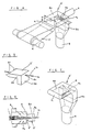
- FIGs. 4 and 5 are perspective views showing a pneumatic duct D' of the present invention.
- a pneumatic tube 6e is formed with a rectangular cross-section and with an opening a, which has a width 1 2 and a height I,.
- the aforementioned pneumatic tube 6e is formed at its downstream end with an opening a 2 which has communication with the suction tube 8 and which is formed in a rectangular shape having a width d 2 and a height d i .
- a suction portion 8a having the aforementioned opening a 2 , has a rectangular cross-section, which is gradually deformed into a circular shape which connects with a suction tube 8 which in turn is connected with a vacuum system.
- the openings a, and a 2 exert remarkable influences upon the amount of free or floating fibers which are generated either over the apron 5' or in the gap S between the aprons 5 and 5'.
- the opening a 2 is similar to the opening a, of the pneumatic tube 6e, having a rectangular cross-section where it is connected with suction tube 8.
- Pneumatic tube 6e has a cross-sectional shape identical to or slightly reduced from the cross-sectional shape of the opening a,'throughout its entire length. Moreover, the opening a 2 formed in the upper or lower wall of the pneumatic tube 6e may also be shaped identical to or slightly reduced from the aforementioned inlet opening a,.
- Fig. 6 is a view illustrating the action of the pneumatic duct D' according to the present invention.
- the air flows which flow along the twisted yarn 16, effectively occur as indicated by arrows A 2 , so that many free fibers F' are produced and they can be transferred along said twisted yarn 1b for a while without being trapped by said twisted yarn 1b.
- the free fibers F' are twisted as they are gradually wrapped around the surface of yarn 1b before they reach the false twister.
- Fig. 7 shows another embodiment in the present invention.
- Pneumatic tube 6e has rounded, arcuate shaped corners, the angle and the portion connecting with suction tube 8a is also formed into an arcuate shape so that the air flow required in the present invention may be smoothly generated.
- the openings a i and a 2 are made to have a generally rectangular cross-section so that the air flows A 2 shown in Fig. 6 are positively generated above apron 5' by the action of the pneumatic duct D' making it possible to increase the amount of the free fibers F'.
- pneumatic tube 6e may have side walls formed with triangular walls 6f which project toward aprons 5 and 5'. As a result, the direction of the air flow passing between the aprons 5 and 5' can be regulated to some extent to increase the amount of free fibers F'.
- the pneumatic duct By constructing the pneumatic duct in the aforementioned manner according to the present invention, it is possible to increase the amount of the free fibers which wrap around the bundle of main fibers, i.e., the bundle of core fibers. According to the present invention, therefore, free fibers can be generated in a sufficient amount, even if the twisting action is weak, so that a spun yarn having high strength and an excellent feeling can be made.
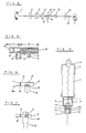
- Fig. 8 shows another embodiment of the present invention, in which two pneumatic false twisting nozzles are arranged in series.
- a roving or sliver 1 is drafted by the roller draft units 2, 3 and 4.
- the greater part of the fibers are false-twisted by pneumatic false twisting nozzle 9, but a part of the fibers are twisted into the bundle of false twisted fibers after they have been delivered by pneumatic tube 6.
- the false twisted fiber bundle is then more densely twisted by the action of nozzle 9' which has a false twist direction opposite to that of nozzle 9.
- the fiber bundle thus prepared is then detwisted while it is passing through false twisting nozzle 9', so that the aforementioned fibers which are twisted later are wrapped around the surface of the yarn.
- the yarn thus prepared is nipped by delivery rollers 10 and taken up by a winder to form package 11.
- pneumatic false twisting nozzle 9 In front of pneumatic false twisting nozzle 9, there is disposed pneumatic duct 6 through which air is pulled by the action of suction tube 8 connected with a vacuum system through opening 7 formed at the trailing end of pneumatic tube 8.
- Fig. 9 shows the pneumatic duct and the false twisting nozzle of the prior art. More specifically, Fig. 9 is a sectional side elevation showing the apparatus in which a pneumatic duct 17 and a pneumatic false twisting nozzle 16 are combined.
- Pneumatic duct 17 is constructed of a cylindrical pneumatic tube 18 and a suction tube 12 which is connected with an opening 19 formed at the trailing end of pneumatic tube 18.
- False twisting nozzle 16 is provided at its center with a yarn guide hole 13 and an injection hole 14 which communicates with the former for swirling the air flow. Compressed air is supplied from a compressed air supply tube 15 and is injected from injection hole 14 thereby false twisting the yarn passing through yarn guide hole 13.
- Pneumatic duct 17 of the prior art is constructed such that the minimum effective area N of pneumatic tube 18 is made sufficiently larger than the effective area n of vacuum opening 19 and such that the fiber bundle which has been delivered from front rollers 4 is smoothly pulled into suction tube 12 when the yarn is cut.
- the fiber bundle is composed of 100% synthetic fibers, such as acrylic fibers or polyester fibers
- few floating or free fibers are pulled into the suction tube during the spinning operation even if the pneumatic tube is opened to satisfy an inequality of N>n between the effective area N of the pneumatic tube and the effective area n of the vacuum opening, and the amount of fibers pulled into the suction tube is generally 0.05 to 0.17% of the total amount of the delivered fibers so that no special problems arise.
- the effective area n of vacuum opening 19 may be made larger than the minimum effective area of pneumatic tube 18, as shown in Fig. 10.
- an inlet 18a may have an opening with a horn-like shape.
- Fig. 11 shows another embodiment of the present invention.
- Pneumatic tube 18 has its trailing end portion opened over the entire circumference, and the opening communicating with suction tube 12 extends along the entire circumference of pneumatic tube 18.
- the sectional area n of opening 19 is made far larger than the minimum effective area N of pneumatic tube 18.
- the boundary limit value of the ratio N/n of the effective areas is 1, and the preferable effects of the pneumatic suction tube are obtained when N/n:-50.7.
- the ratio N/n is preferably set at a smaller value. If the suction of the free fibers is taken into consideration, however, it is necessary that the hole diameter in the N portion be at least 2 mm, that is, that a relationship of about N?rlmm2 hold.
- the maximum value of the effective area n varies in accordance with the construction of the spinning frame, but is not especially limitative.
- the free fibers are delivered around the core fiber bundle which has been twisted. It is, therefore, necessary that the opening communicating with the vacuum system not obstruct the delivery of the free fibers.
- the amount of fibers pulled into the suction tube can be reduced to less than 1 %.
- the present invention can be modifed as shown in Fig. 12.
- the spinning frame is constructed to satisfy the following relationships: wherein: I is the width of a bundle of fibers 20 before it is fed to pneumatic tube 6, i.e., the width of the fiber bundle before it is reduced by the twisting action of the pneumatic false twisting nozzle; 1 2 is the width of inlet 111 of a fiber bundle guide passage 110 of pneumatic tube 6; d 2 is the width of the opening of a fluid suction port 112 (or the fluid outlet here an aspirator is used); and p is the diameter of an inlet 120 of the fluid twisting nozzle 9.
- the collecting or trapping effect of the peripheral fibers around the fiber bundle in the pneumatic tube is influenced not only by the relationship between the width I of the fiber bundle and the width 1 2 of the inlet of the fiber bundle guide passage of the pneumatic tube but also by the kind of ballooning action which is established by the rotations of the yarn. Since the intensity of this ballooning action of the yarn is related to the diameter p of the inlet of the fluid twisting nozzle, the width d 2 of the fluid suction port or outlet port of the pneumatic tube is determined from the relationship with the diameter p of the inlet of the fluid twisting nozzle.
- reference numerals 121, 122 and 123 indicate a twisting portion, a compressed air chamber and an injection hole, respectively.
- the remaining reference numerals are the same as those which have already been described.
- the aprons are not required, as has been described hereinbefore.
- the measured values of the strength of the spun yarn produced- are tabulated in Table 1.
- Yarn produced according to the present invention exhibited increased strength.
- the average strength of the yarn produced according to the present invention was 2.15 times that of yarn produced by prior art apparatus and the minimum strength of the yarn produced according to the present invention was 8 times greater than that of the yarn which was spun by the use of the pneumatic duct of the prior art.
- Slivers made of polyester staple having single fiber denier of 3d were fed to an apparatus similar to that of Example 1 to produce a spun yarn of 1/6 Nm.
- the spinning conditions were as follows: .
- the measured values of the strength of the spun yarn are tabulated in Table 2.
- the strength of the yarn produced according to the present invention was greater.
- the average strength of the yarn produced according to the present invention was 1.17 times that of yarn produced by prior art apparatus and the minimum strength of yarn produced according to the present invention was 2.3 times greater than that of the spun yarn which was made by the use of the pneumatic duct of the prior art.
- the spinning operation was conducted by the use of a vortex flow type fine spinning frame which had a three-line draft unit and a pair of upper and lower aprons having their leading ends opened and which was equipped with a rectangular pneumatic duct and a-pneumatic false twisting nozzle downstream of these aprons, as shown in Fig. 1.
- the roving used was a blend of 65% polyester of 1.3dx38 mm and 35% combed sliver of American cotton and was 0.55 g/m.
- the spinning operation was conducted under the same conditions as those of Example 3, and the ratio of fibers pulled was investigated for various N/n ratios.
- the results are tabulated in Table 4, from which it is found that the effect is appreciable for N/n:-51.0 and high for N/n ⁇ 0.7.
- a considerable effect cannot be obtained for a diameter at the N portion less than 4 mm.
- a diameter less than 2 mm is not preferable because bundling deterioration of the free fibers due to the reduction in the suction flow rate and clogging with fibers when the yarn is cut appear to take place.
- the pneumatic tube was replaced by a tube having a horn-shaped fiber bundle guide passage throughout its length, and the same slivers as the aforementioned ones were spun under the same conditions to produce a fasciated spun yarn B.
- the number of fuzz having a length larger than 5 mm, the number of deteriorated wrapping fibers, the number of drawing neps after two passages through a winder and the weaving properties in producing a blanket when the spun yarns A and B were used as ground yarns were examined.
- the results are tabulated in Table 5.
- the blanket which was woven of the fasciated spun yarn A had an excellent quality and was found not to be substantially different from a blanket made of a ring spun yarn of 30 S/2.
Landscapes
- Engineering & Computer Science (AREA)
- Mechanical Engineering (AREA)
- Textile Engineering (AREA)
- Spinning Or Twisting Of Yarns (AREA)
Claims (6)

Applications Claiming Priority (4)
| Application Number | Priority Date | Filing Date | Title |
|---|---|---|---|
| JP100557/81 | 1981-06-30 | ||
| JP10055781A JPS584828A (ja) | 1981-06-30 | 1981-06-30 | 空気渦流精紡機のニユ−マダクト |
| JP105025/81 | 1981-07-07 | ||
| JP10502581A JPS588132A (ja) | 1981-07-07 | 1981-07-07 | 空気渦流精紡機のニユ−マダクト |
Publications (3)
| Publication Number | Publication Date |
|---|---|
| EP0068507A2 EP0068507A2 (de) | 1983-01-05 |
| EP0068507A3 EP0068507A3 (en) | 1985-03-06 |
| EP0068507B1 true EP0068507B1 (de) | 1987-09-23 |
Family
ID=26441563
Family Applications (1)
| Application Number | Title | Priority Date | Filing Date |
|---|---|---|---|
| EP82105837A Expired EP0068507B1 (de) | 1981-06-30 | 1982-06-30 | Maschine zum Herstellen von gebündelten Garn |
Country Status (5)
| Country | Link |
|---|---|
| US (1) | US4463549A (de) |
| EP (1) | EP0068507B1 (de) |
| AU (1) | AU547278B2 (de) |
| CA (1) | CA1173312A (de) |
| DE (1) | DE3277380D1 (de) |
Families Citing this family (4)
| Publication number | Priority date | Publication date | Assignee | Title |
|---|---|---|---|---|
| CS8203229A (de) * | 1982-05-05 | 1984-05-14 | ||
| IN161355B (de) * | 1983-07-01 | 1987-11-14 | Rieter Ag Maschf | |
| GB8607326D0 (en) * | 1986-03-25 | 1986-04-30 | Carding Spec Canada | Modifying yarn |
| DE4032940A1 (de) * | 1990-10-17 | 1992-04-23 | Fritz Stahlecker | Vorrichtung zum pneumatischen falschdrallspinnen |
Family Cites Families (14)
| Publication number | Priority date | Publication date | Assignee | Title |
|---|---|---|---|---|
| US3009309A (en) * | 1956-07-16 | 1961-11-21 | Du Pont | Fluid jet twist crimping process |
| US3079746A (en) * | 1961-10-23 | 1963-03-05 | Du Pont | Fasciated yarn, process and apparatus for producing the same |
| FR1453534A (fr) * | 1965-09-17 | 1966-06-03 | Du Pont | Fil enveloppé, procédé et appareil pour la fabrication de ce fil |
| US3367095A (en) * | 1967-06-30 | 1968-02-06 | Du Pont | Process and apparatus for making wrapped yarns |
| US3732684A (en) * | 1971-02-23 | 1973-05-15 | Du Pont | Product and process |
| JPS5243256B2 (de) * | 1973-04-10 | 1977-10-29 | ||
| US4003194A (en) * | 1973-04-10 | 1977-01-18 | Toray Industries, Inc. | Method and apparatus for producing helically wrapped yarn |
| DE2533655C2 (de) * | 1974-10-09 | 1986-11-27 | Toray Industries, Inc., Tokio/Tokyo | Spinnmaschine zur Herstellung von gebündeltem Garn |
| JPS51130334A (en) * | 1975-05-06 | 1976-11-12 | Murata Machinery Ltd | Apparatus for making spun yarns |
| JPS52107349A (en) * | 1976-03-04 | 1977-09-08 | Murata Machinery Ltd | Spun yarn and method of producing same |
| JPS53119334A (en) * | 1977-03-24 | 1978-10-18 | Murata Machinery Ltd | Direct spinning device |
| US4114358A (en) * | 1977-05-06 | 1978-09-19 | Toray Industries, Inc. | Method and apparatus for commencing the yarn forming operation of a fasciated yarn |
| JPS5853091B2 (ja) * | 1978-07-10 | 1983-11-26 | 東レ株式会社 | 多色糸およびその製造方法 |
| DE3023936A1 (de) * | 1979-07-27 | 1981-02-19 | Ernst Dr Fehrer | Vorrichtung zum herstellen eines garnes |
-
1982
- 1982-06-21 US US06/390,682 patent/US4463549A/en not_active Expired - Lifetime
- 1982-06-22 AU AU85109/82A patent/AU547278B2/en not_active Expired
- 1982-06-30 EP EP82105837A patent/EP0068507B1/de not_active Expired
- 1982-06-30 DE DE8282105837T patent/DE3277380D1/de not_active Expired
- 1982-06-30 CA CA000406387A patent/CA1173312A/en not_active Expired
Also Published As
| Publication number | Publication date |
|---|---|
| EP0068507A2 (de) | 1983-01-05 |
| AU547278B2 (en) | 1985-10-10 |
| DE3277380D1 (en) | 1987-10-29 |
| AU8510982A (en) | 1983-01-06 |
| CA1173312A (en) | 1984-08-28 |
| EP0068507A3 (en) | 1985-03-06 |
| US4463549A (en) | 1984-08-07 |
Similar Documents
| Publication | Publication Date | Title |
|---|---|---|
| US3604194A (en) | Fiber supply method and apparatus in an open-end spinning system utilizing airflow and centrifugal force | |
| US4437302A (en) | False twisting air nozzle | |
| US4565063A (en) | Method and apparatus for false twist spinning | |
| US3438094A (en) | High speed drafting process | |
| EP0094011B1 (de) | Vorrichtung zur Herstellung von Effektgarn | |
| EP0068507B1 (de) | Maschine zum Herstellen von gebündelten Garn | |
| JPS6320923B2 (de) | ||
| US4429523A (en) | Process for making fasciated spun yarn | |
| US7328569B2 (en) | Arrangement for producing a spun thread from a staple fiber strand | |
| US4450678A (en) | Air nozzle utilized for fasciated yarn spinning | |
| JPS6018338B2 (ja) | ノズル | |
| JPS6136089B2 (de) | ||
| JPH0770833A (ja) | 空気紡績装置 | |
| JPH0586510A (ja) | 空気紡績ノズル | |
| JPS643963B2 (de) | ||
| JPS6136090B2 (de) | ||
| JPH07197330A (ja) | 空気紡績装置 | |
| JPS584828A (ja) | 空気渦流精紡機のニユ−マダクト | |
| JPS627289B2 (de) | ||
| JPH0634373Y2 (ja) | 紡績糸の製造装置 | |
| JPH0718522A (ja) | 空気紡績装置 | |
| JPH03241017A (ja) | 精紡機 | |
| JPH0320487B2 (de) | ||
| JPS58208424A (ja) | 結束紡績糸の製造方法および装置 | |
| JPS59137519A (ja) | 吸引管 |
Legal Events
| Date | Code | Title | Description |
|---|---|---|---|
| PUAI | Public reference made under article 153(3) epc to a published international application that has entered the european phase |
Free format text: ORIGINAL CODE: 0009012 |
|
| AK | Designated contracting states |
Designated state(s): CH DE FR GB IT LI |
|
| PUAL | Search report despatched |
Free format text: ORIGINAL CODE: 0009013 |
|
| AK | Designated contracting states |
Designated state(s): CH DE FR GB IT LI |
|
| 17P | Request for examination filed |
Effective date: 19850703 |
|
| 17Q | First examination report despatched |
Effective date: 19860312 |
|
| ITF | It: translation for a ep patent filed | ||
| GRAA | (expected) grant |
Free format text: ORIGINAL CODE: 0009210 |
|
| AK | Designated contracting states |
Kind code of ref document: B1 Designated state(s): CH DE FR GB IT LI |
|
| ET | Fr: translation filed | ||
| REF | Corresponds to: |
Ref document number: 3277380 Country of ref document: DE Date of ref document: 19871029 |
|
| PLBE | No opposition filed within time limit |
Free format text: ORIGINAL CODE: 0009261 |
|
| STAA | Information on the status of an ep patent application or granted ep patent |
Free format text: STATUS: NO OPPOSITION FILED WITHIN TIME LIMIT |
|
| 26N | No opposition filed | ||
| ITTA | It: last paid annual fee | ||
| PGFP | Annual fee paid to national office [announced via postgrant information from national office to epo] |
Ref country code: FR Payment date: 20010611 Year of fee payment: 20 |
|
| PGFP | Annual fee paid to national office [announced via postgrant information from national office to epo] |
Ref country code: DE Payment date: 20010625 Year of fee payment: 20 |
|
| PGFP | Annual fee paid to national office [announced via postgrant information from national office to epo] |
Ref country code: GB Payment date: 20010627 Year of fee payment: 20 |
|
| PGFP | Annual fee paid to national office [announced via postgrant information from national office to epo] |
Ref country code: CH Payment date: 20010628 Year of fee payment: 20 |
|
| REG | Reference to a national code |
Ref country code: GB Ref legal event code: IF02 |
|
| PG25 | Lapsed in a contracting state [announced via postgrant information from national office to epo] |
Ref country code: LI Free format text: LAPSE BECAUSE OF EXPIRATION OF PROTECTION Effective date: 20020629 Ref country code: GB Free format text: LAPSE BECAUSE OF EXPIRATION OF PROTECTION Effective date: 20020629 Ref country code: CH Free format text: LAPSE BECAUSE OF EXPIRATION OF PROTECTION Effective date: 20020629 |
|
| REG | Reference to a national code |
Ref country code: GB Ref legal event code: PE20 Effective date: 20020629 |
|
| REG | Reference to a national code |
Ref country code: CH Ref legal event code: PL |