EP0160459A2 - Verfahren zur Herstellung von Anzeigeentladungsgeräten - Google Patents
Verfahren zur Herstellung von Anzeigeentladungsgeräten Download PDFInfo
- Publication number
- EP0160459A2 EP0160459A2 EP85302738A EP85302738A EP0160459A2 EP 0160459 A2 EP0160459 A2 EP 0160459A2 EP 85302738 A EP85302738 A EP 85302738A EP 85302738 A EP85302738 A EP 85302738A EP 0160459 A2 EP0160459 A2 EP 0160459A2
- Authority
- EP
- European Patent Office
- Prior art keywords
- lab
- discharge
- powder
- paste
- cathode
- Prior art date
- Legal status (The legal status is an assumption and is not a legal conclusion. Google has not performed a legal analysis and makes no representation as to the accuracy of the status listed.)
- Granted
Links
Images

Classifications
-
- H—ELECTRICITY
- H01—ELECTRIC ELEMENTS
- H01J—ELECTRIC DISCHARGE TUBES OR DISCHARGE LAMPS
- H01J11/00—Gas-filled discharge tubes with alternating current induction of the discharge, e.g. alternating current plasma display panels [AC-PDP]; Gas-filled discharge tubes without any main electrode inside the vessel; Gas-filled discharge tubes with at least one main electrode outside the vessel
- H01J11/20—Constructional details
- H01J11/22—Electrodes, e.g. special shape, material or configuration
-
- H—ELECTRICITY
- H01—ELECTRIC ELEMENTS
- H01J—ELECTRIC DISCHARGE TUBES OR DISCHARGE LAMPS
- H01J17/00—Gas-filled discharge tubes with solid cathode
- H01J17/02—Details
- H01J17/04—Electrodes; Screens
- H01J17/06—Cathodes
- H01J17/063—Indirectly heated cathodes, e.g. by the discharge itself
-
- H—ELECTRICITY
- H01—ELECTRIC ELEMENTS
- H01J—ELECTRIC DISCHARGE TUBES OR DISCHARGE LAMPS
- H01J11/00—Gas-filled discharge tubes with alternating current induction of the discharge, e.g. alternating current plasma display panels [AC-PDP]; Gas-filled discharge tubes without any main electrode inside the vessel; Gas-filled discharge tubes with at least one main electrode outside the vessel
- H01J11/20—Constructional details
- H01J11/22—Electrodes, e.g. special shape, material or configuration
- H01J11/32—Disposition of the electrodes
-
- H—ELECTRICITY
- H01—ELECTRIC ELEMENTS
- H01J—ELECTRIC DISCHARGE TUBES OR DISCHARGE LAMPS
- H01J9/00—Apparatus or processes specially adapted for the manufacture, installation, removal, maintenance of electric discharge tubes, discharge lamps, or parts thereof; Recovery of material from discharge tubes or lamps
- H01J9/02—Manufacture of electrodes or electrode systems
Definitions
- This invention relates to methods of producing discharge display devices.
- Ni nickel
- Cathode a Ni cathode
- Hg mercury
- a direct current type discharge display panel developed by the present inventors employs a trigger discharging system, and when it is embodied as an XY matrix panel with a large capacity, it is necessary to provide discharge characteristics, (i.e. characteristics of a trigger discharge and a main discharge) of each display cell which are uniform to a certain degree.
- discharge characteristics i.e. characteristics of a trigger discharge and a main discharge
- Hg mercury
- a non-uniform distribution of the mercury commonly occurs due to change on standing, and it is difficult to retain uniform discharge characteristics for a long time. For this reason, it would be desirable to provide a discharge display panel in which no mercury is sealed.
- mercury should not in any event be used in view of the dangers associated with the use of mercury in a closed environment.
- LaB 6 Lanthanum boride
- LaB 6 has a low discharge holding voltage, and is stable in physical and chemical properties, thus meeting the above-mentioned requirements.
- an LaB6 cathode has not yet reached practical use for the reason that production employing a thin-film evaporation method or a plasma spraying method is complicated and results in an increase in cost.
- Another reason is that the electrode cannot be formed in connection with the other panel structure by a thick-film printing method at low cost.
- an LaB 6 cathode In a case where an LaB 6 cathode is intended to be formed by the thick-film printing method, it is generally burnt in an atmosphere of nitrogen (N 2 ) at 800°C to 900°C after printing and application. However, since a substrate of the discharge display panel is of glass, the temperature is permitted to be raised up only to about 600°C, and since a structure such as the other electrodes and a barrier is of oxide, a burning step is usually carried out in the air. For these reasons, it is difficult to form the LaB 6 cathode.
- N 2 nitrogen
- LaB 6 has a high melting point of about 2300°C, and therefore it cannot be sintered at a temperature of about 600°C, with a result that the resistance after formation of the cathode is disadvantageously increased to 10 9 ohms or more.
- a binder substance such as frit glass is generally mixed with LaB 6 powder so as to obtain bonding strength between the particles of the LaB 6 powder.
- a method of producing a discharge display device comprising the steps of applying to a base electrode a paste prepared by mixing LaB 6 powder with alkali glass powder in a proportion of 20 to 40 wt. % of glass powder with respect to the LaB 6 powder, burning the paste, and activating the paste by gas discharge with a large current following an exhaustion step to form an LaB 6 cathode on the base electrode.
- a preferred method embodying the present invention and described hereinafter makes it possible easily to form an LaB 6 cathode by a thick-film printing method and obtain a discharge display device having improved characteristics such as low driving voltage, long life and high discharge efficiency.
- the preferred method makes it possible easily to form an LaB6 cathode by a so-called thick-film printing method by the steps of applying the LaB 6 paste, and subsequently effecting activation treatment by gas discharge with a large current.
- the glass binder is contained in the LaB 6 paste, an LaB 6 cathode having a large adhesive strength may be obtained. Additionally, since an alkali glass powder having an ionic conducting property is used in the preferred method as the glass binder, and the alkali glass powder is mixed in a proportion of 20 to 40 wt. % with respect to the LaB6 powder, the activation treatment may be effected satisfactorily.
- Methods embodying the invention can be used to produce a discharge display device with a large capacity and a large area. Further, formation of the LaB 6 cathode is simplified as compared with an evaporation method, etc., thus reducing cost.
- the possibility of formation of an LaB 6 cathode imparts the following advantages.
- the driving voltage in the discharge display device may be reduced and, accordingly, the circuit cost may be reduced by using an integrated circuit (IC).
- Power consumption may be reduced.
- LaB 6 is superior in anti-sputtering performance, and is stable in physical and chemical properties, and the sputter voltage is decreased due to the low driving voltage, the life of the discharge display device is extended. High luminance may be achieved by improvement in discharge efficiency and reduction in power consumption. Further, the area of application of this type of discharge display device is expanded due to the elimination of mercury.
- the discharge display device is a direct current type discharge display panel 1 of a trigger discharge system.
- the discharge panel 1 comprises a front glass substrate 2, a rear glass substrate 3, and anodes 4 and cathodes 5 of XY matrix shape.
- the anodes 4 are partitioned from each other by insulative barriers 6.
- Trigger electrodes 8, formed of aluminium (Al), for example, are arranged on the rear glass substrate 3 in parallel relation with the cathodes 5, an insulative dielectric layer 7 being disposed under the cathodes 5.
- the display panel 1 is manufactured in the following manner. First, the anodes 4 and the insulative barriers 6 are formed on the front glass substrate 2 by a thick-film printing method. Similarly, the trigger electrodes 8, the insulative dielectric layer 7 and the cathodes 5 are formed sequentially on the rear glass substrate 3 by the thick-film printing method. Each of these component parts is burnt after printing. Then, the glass substrates 2 and 3 are arranged in opposition to one another, with the anodes 4 and the cathodes 5 crossing at right angles, and are frit-sealed about the periphery. Thereafter, heating exhaustion, gas sealing (for example, Ne-Ar gas) and final sealing are carried out to complete the display panel 1.
- gas sealing for example, Ne-Ar gas
- a driving voltage is selectively applied to the anodes 4 and the cathodes 5 to generate discharge luminescence at crossing points between the selected anodes 4 and cathodes 5, thereby effecting a display in a linearly sequential manner.
- a trigger voltage is applied to the trigger electrodes 8 prior to effecting discharge between the anodes 4 and the cathodes 5 to induce a wall voltage on a portion of the insulative dielectric layer 7 corresponding to the trigger electrodes 8 and effect momentary discharge between the insulative dielectric layer 7 and the selected cathodes 5.
- a gas space along the cathodes 5 is ionised, so that subsequent discharge between the selected anodes 4 and cathodes 5 may be effected easily.
- a preferred embodiment of the present invention described below is directed to a method of forming the cathodes 5 in the discharge display panel by the thick-film printing method.
- an LaB6 paste comprising LaB 6 powder, an inorganic binder and a suitable vehicle (solvent) is prepared as a preliminary step.
- the LaB 6 powder raw material is selected in such a manner that an average particle size thereof is not more than several micrometres, preferably 1 to 3 micrometres, and powder having an average particle size of not less than 5 micrometres is present in a proportion of not more than 5% with respect to the total amount of LaB 6 powder.
- the LaB 6 powder is, in general, insufficiently unbound from its sintered state, it is further finely pulverised with a ball mill.
- An alkali glass is used as the inorganic binder, because a certain degreee of ionic conduction is required in a subsequent activation step.
- a fine powder of the alkali glass is added in the amount of 0.2 to 0.4 parts by weight with respect to 1 part by weight of the LaB 6 powder. If the amount of the alkali glass fine powder is too small, activation is rendered non-uniform, while, if the amount is too great, the activation is difficult to effect.
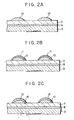
- a conductive paste such as a nickel (Ni) paste is first applied and printed along a cathode pattern to be formed on the insulative dielectric layer 7 formed on the rear glass substrate 3, and is burnt to form Ni base electrodes 10.
- the Ni base electrodes 10 serve as lead wires for supplying current to LaB 6 cathodes which will be formed subsequently.
- the LaB 6 paste mentioned above is printed on each Ni base electrode 10 and is then burnt in dry air at 500°C to 6000 e for thirty minutes to form an LaB 6 layer 11.
- the resistance after being burnt is rendered high, namely not less than 10 9 ohms.
- the current density during activation is about 2 to 5 A/cm 2.
- Figure 3 shows the change in a holding voltage during activation, provided that the activation treatment is carried out at a current density of 3 A/cm 2 with 0.5 sec ON - 0.5 see OFF.
- a firing potential is high (200 V or more) and dispersion is large.
- the firing potential is lowered and is stabilised in two to three hours. Further, dispersion becomes small after about one hour has elapsed.
- the holding voltage in a normal driving region after activation is about 110 V. Comparatively, in the case of an Ni cathode, the holding voltage is about 150 V.
- the LaB 6 paste is applied to and printed on the base electrode, and is burnt, activation thereafter being carried out by gas discharge with a large current after an exhaustion step, thereby permitting the LaB6 cathode to be formed by a so-called thick-film printing method.
- the LaB 6 paste contains a glass binder, the bonding strength between each of the LaB 6 cathodes and the base electrode is large, and the LaB 6 cathodes are not separated easily even if they are slightly rubbed during the frit sealing step.
- an alkali glass having ionic conducting property is used as the glass binder, the subsequent activation treatment may be effected securely.
- each LaB 6 paste layer is burned in air at about 500 0 C to 600°C, the rear glass substrate is not damaged, and the other oxide structures are not adversely influenced.
Landscapes
- Engineering & Computer Science (AREA)
- Manufacturing & Machinery (AREA)
- Chemical & Material Sciences (AREA)
- Materials Engineering (AREA)
- Physics & Mathematics (AREA)
- Plasma & Fusion (AREA)
- Gas-Filled Discharge Tubes (AREA)
Applications Claiming Priority (2)
| Application Number | Priority Date | Filing Date | Title |
|---|---|---|---|
| JP59079216A JPS60221926A (ja) | 1984-04-19 | 1984-04-19 | 放電表示装置の製造方法 |
| JP79216/84 | 1984-04-19 |
Publications (3)
| Publication Number | Publication Date |
|---|---|
| EP0160459A2 true EP0160459A2 (de) | 1985-11-06 |
| EP0160459A3 EP0160459A3 (en) | 1987-05-13 |
| EP0160459B1 EP0160459B1 (de) | 1990-03-14 |
Family
ID=13683730
Family Applications (1)
| Application Number | Title | Priority Date | Filing Date |
|---|---|---|---|
| EP85302738A Expired - Lifetime EP0160459B1 (de) | 1984-04-19 | 1985-04-18 | Verfahren zur Herstellung von Anzeigeentladungsgeräten |
Country Status (6)
| Country | Link |
|---|---|
| US (1) | US4599076A (de) |
| EP (1) | EP0160459B1 (de) |
| JP (1) | JPS60221926A (de) |
| KR (1) | KR930000380B1 (de) |
| CA (1) | CA1251418A (de) |
| DE (1) | DE3576607D1 (de) |
Cited By (5)
| Publication number | Priority date | Publication date | Assignee | Title |
|---|---|---|---|---|
| EP0450547A3 (en) * | 1990-04-02 | 1991-11-21 | Matsushita Electric Industrial Co., Ltd. | Gas discharge-type display panel comprising a composite oxide cathode |
| EP0827176A3 (de) * | 1996-08-16 | 2000-03-08 | Tektronix, Inc. | Zerstäubungsfeste, leitende Überzüge mit verbesserter Elektronenemittierung für Kathodenelektroden in Gleichstromplasma-Adressierungsvorrichtungen |
| FR2798509A1 (fr) * | 1999-09-13 | 2001-03-16 | Thomson Multimedia Sa | Melange pour realiser des electrodes et procede de formation d'electrodes sur un substrat transparent |
| EP1150320A4 (de) * | 1999-10-19 | 2007-08-01 | Matsushita Electric Industrial Co Ltd | Herstellungsverfahren einer metallelektrode |
| EP2036110A4 (de) * | 2006-06-30 | 2010-08-18 | Lg Electronics Inc | Plasmaanzeigetafel |
Families Citing this family (18)
| Publication number | Priority date | Publication date | Assignee | Title |
|---|---|---|---|---|
| JPS61284030A (ja) * | 1985-06-10 | 1986-12-15 | Hitachi Ltd | 気体放電表示パネル用陰極 |
| DE3752249T2 (de) * | 1986-07-04 | 1999-07-08 | Canon K.K., Tokio/Tokyo | Elektronen emittierende Vorrichtung |
| USRE40062E1 (en) | 1987-07-15 | 2008-02-12 | Canon Kabushiki Kaisha | Display device with electron-emitting device with electron-emitting region insulated from electrodes |
| USRE40566E1 (en) | 1987-07-15 | 2008-11-11 | Canon Kabushiki Kaisha | Flat panel display including electron emitting device |
| USRE39633E1 (en) | 1987-07-15 | 2007-05-15 | Canon Kabushiki Kaisha | Display device with electron-emitting device with electron-emitting region insulated from electrodes |
| JPS6413655U (de) * | 1987-07-16 | 1989-01-24 | ||
| JPS6489242A (en) * | 1987-09-30 | 1989-04-03 | Mitsubishi Electric Corp | Electrode for discharge light source |
| US5209688A (en) * | 1988-12-19 | 1993-05-11 | Narumi China Corporation | Plasma display panel |
| JP2769933B2 (ja) * | 1991-06-17 | 1998-06-25 | 株式会社ノリタケカンパニーリミテド | 直流型放電表示管およびその陰極形成用組成物 |
| US5428263A (en) * | 1992-01-07 | 1995-06-27 | Mitsubishi Denki Kabushiki Kaisha | Discharge cathode device with stress relieving layer and method for manufacturing the same |
| TW368671B (en) * | 1995-08-30 | 1999-09-01 | Tektronix Inc | Sputter-resistant, low-work-function, conductive coatings for cathode electrodes in DC plasma addressing structure |
| TW383123U (en) * | 1997-07-18 | 2000-02-21 | Koninkl Philips Electronics Nv | Display device |
| US6077617A (en) * | 1998-08-26 | 2000-06-20 | Board Of Regents Of The University Of Nebraska | Rare-earth boride thin film system |
| US6025038A (en) * | 1998-08-26 | 2000-02-15 | Board Of Regents Of The University Of Nebraska | Method for depositing rare-earth boride onto a substrate |
| JP2003509809A (ja) * | 1999-09-08 | 2003-03-11 | コーニンクレッカ フィリップス エレクトロニクス エヌ ヴィ | 電極保護を有する画像表示装置 |
| JP2002075227A (ja) * | 2000-06-14 | 2002-03-15 | Sharp Corp | 気体放電表示装置およびプラズマアドレス液晶表示装置ならびにその製造方法 |
| JP3960064B2 (ja) * | 2002-02-05 | 2007-08-15 | 松下電器産業株式会社 | プラズマディスプレイパネルの製造方法 |
| RU2549536C1 (ru) * | 2013-12-03 | 2015-04-27 | Федеральное государственное бюджетное образовательное учреждение высшего профессионального образования "Рязанский государственный радиотехнический университет" | Способ управления газоразрядной индикаторной панелью постоянного тока |
Family Cites Families (6)
| Publication number | Priority date | Publication date | Assignee | Title |
|---|---|---|---|---|
| US2172207A (en) * | 1936-09-19 | 1939-09-05 | Siemens Ag | Glow cathode |
| US4126809A (en) * | 1975-03-10 | 1978-11-21 | Owens-Illinois, Inc. | Gas discharge display panel with lanthanide or actinide family oxide |
| FR2445605A1 (fr) * | 1978-12-27 | 1980-07-25 | Thomson Csf | Cathode a chauffage direct et tube electronique haute frequence comportant une telle cathode |
| US4393326A (en) * | 1980-02-22 | 1983-07-12 | Okaya Electric Industries Co., Ltd. | DC Plasma display panel |
| US4317750A (en) * | 1980-08-22 | 1982-03-02 | Ferro Corporation | Thick film conductor employing nickel oxide |
| JPS57180046A (en) * | 1981-04-28 | 1982-11-05 | Okaya Denki Sangyo Kk | Panel for displaying dc gas discharge |
-
1984
- 1984-04-19 JP JP59079216A patent/JPS60221926A/ja active Granted
-
1985
- 1985-04-11 US US06/721,955 patent/US4599076A/en not_active Expired - Lifetime
- 1985-04-11 CA CA000478802A patent/CA1251418A/en not_active Expired
- 1985-04-15 KR KR1019850002507A patent/KR930000380B1/ko not_active Expired - Lifetime
- 1985-04-18 EP EP85302738A patent/EP0160459B1/de not_active Expired - Lifetime
- 1985-04-18 DE DE8585302738T patent/DE3576607D1/de not_active Expired - Lifetime
Cited By (8)
| Publication number | Priority date | Publication date | Assignee | Title |
|---|---|---|---|---|
| EP0450547A3 (en) * | 1990-04-02 | 1991-11-21 | Matsushita Electric Industrial Co., Ltd. | Gas discharge-type display panel comprising a composite oxide cathode |
| US5225732A (en) * | 1990-04-02 | 1993-07-06 | Matsushita Electric Industrial Co., Ltd. | Gas discharge-type display panel comprising a composite oxide cathode |
| EP0827176A3 (de) * | 1996-08-16 | 2000-03-08 | Tektronix, Inc. | Zerstäubungsfeste, leitende Überzüge mit verbesserter Elektronenemittierung für Kathodenelektroden in Gleichstromplasma-Adressierungsvorrichtungen |
| FR2798509A1 (fr) * | 1999-09-13 | 2001-03-16 | Thomson Multimedia Sa | Melange pour realiser des electrodes et procede de formation d'electrodes sur un substrat transparent |
| WO2001020637A1 (fr) * | 1999-09-13 | 2001-03-22 | Thomson Multimedia | Melange pour realiser des electrodes et procede de formation d'electrodes sur un substrat transparent |
| EP1150320A4 (de) * | 1999-10-19 | 2007-08-01 | Matsushita Electric Industrial Co Ltd | Herstellungsverfahren einer metallelektrode |
| EP2036110A4 (de) * | 2006-06-30 | 2010-08-18 | Lg Electronics Inc | Plasmaanzeigetafel |
| US7999472B2 (en) | 2006-06-30 | 2011-08-16 | Lg Electronics Inc. | Plasma display panel |
Also Published As
| Publication number | Publication date |
|---|---|
| JPH0533488B2 (de) | 1993-05-19 |
| JPS60221926A (ja) | 1985-11-06 |
| KR930000380B1 (ko) | 1993-01-16 |
| EP0160459A3 (en) | 1987-05-13 |
| US4599076A (en) | 1986-07-08 |
| KR850007530A (ko) | 1985-12-04 |
| CA1251418A (en) | 1989-03-21 |
| DE3576607D1 (de) | 1990-04-19 |
| EP0160459B1 (de) | 1990-03-14 |
Similar Documents
| Publication | Publication Date | Title |
|---|---|---|
| EP0160459B1 (de) | Verfahren zur Herstellung von Anzeigeentladungsgeräten | |
| US5557168A (en) | Gas-discharging type display device and a method of manufacturing | |
| US4393326A (en) | DC Plasma display panel | |
| US4600397A (en) | Method of producing discharge display device | |
| US4746838A (en) | Ink for forming resistive structures and display panel containing the same | |
| US5705097A (en) | Fluorescent display device with conductive paste having Ag, Sb, and Zn | |
| JP2633389B2 (ja) | ガス放電型表示パネル | |
| WO1985000247A1 (en) | Conductor composition and devices using it | |
| JPH071673B2 (ja) | ガス放電型表示パネルの製造方法 | |
| JPH0495332A (ja) | 放電電極 | |
| JP2769933B2 (ja) | 直流型放電表示管およびその陰極形成用組成物 | |
| JP3016537B2 (ja) | 表示放電管用冷陰極の製造方法 | |
| JP3703999B2 (ja) | プラズマディスプレイパネル用陰極の製造方法 | |
| JPH03203965A (ja) | スクリーン印刷用ペースト | |
| JPS60221927A (ja) | 放電表示装置の製造方法 | |
| JPH027136B2 (de) | ||
| RU1809475C (ru) | Токопровод щий материал дл изготовлени холодных катодов газоразр дных приборов | |
| JPH0513149A (ja) | 放電装置 | |
| EP0928009A2 (de) | Widerstand zum Gebrauch in einer Elektronenkanone für eine Kathodenstrahlröre und Verfahren zur Herstellung des Widerstands | |
| JPH0778566A (ja) | ガス放電表示パネル及びその形成方法 | |
| JPH01272028A (ja) | ガス放電表示パネルの電極形成方法 | |
| JP2000298261A (ja) | プラズマアドレス液晶表示装置 | |
| JPH03203145A (ja) | 厚膜ペースト | |
| JPH04163826A (ja) | 放電表示管およびその陰極形成用組成物 | |
| JPH03203964A (ja) | スクリーン印刷用ペースト |
Legal Events
| Date | Code | Title | Description |
|---|---|---|---|
| PUAI | Public reference made under article 153(3) epc to a published international application that has entered the european phase |
Free format text: ORIGINAL CODE: 0009012 |
|
| AK | Designated contracting states |
Designated state(s): DE FR GB IT |
|
| PUAL | Search report despatched |
Free format text: ORIGINAL CODE: 0009013 |
|
| AK | Designated contracting states |
Kind code of ref document: A3 Designated state(s): DE FR GB IT |
|
| 17P | Request for examination filed |
Effective date: 19871020 |
|
| 17Q | First examination report despatched |
Effective date: 19881104 |
|
| GRAA | (expected) grant |
Free format text: ORIGINAL CODE: 0009210 |
|
| AK | Designated contracting states |
Kind code of ref document: B1 Designated state(s): DE FR GB IT |
|
| ITF | It: translation for a ep patent filed | ||
| REF | Corresponds to: |
Ref document number: 3576607 Country of ref document: DE Date of ref document: 19900419 |
|
| ET | Fr: translation filed | ||
| PLBE | No opposition filed within time limit |
Free format text: ORIGINAL CODE: 0009261 |
|
| STAA | Information on the status of an ep patent application or granted ep patent |
Free format text: STATUS: NO OPPOSITION FILED WITHIN TIME LIMIT |
|
| 26N | No opposition filed | ||
| ITTA | It: last paid annual fee | ||
| REG | Reference to a national code |
Ref country code: GB Ref legal event code: IF02 |
|
| PGFP | Annual fee paid to national office [announced via postgrant information from national office to epo] |
Ref country code: FR Payment date: 20040408 Year of fee payment: 20 |
|
| PGFP | Annual fee paid to national office [announced via postgrant information from national office to epo] |
Ref country code: GB Payment date: 20040414 Year of fee payment: 20 |
|
| PGFP | Annual fee paid to national office [announced via postgrant information from national office to epo] |
Ref country code: DE Payment date: 20040429 Year of fee payment: 20 |
|
| PG25 | Lapsed in a contracting state [announced via postgrant information from national office to epo] |
Ref country code: GB Free format text: LAPSE BECAUSE OF EXPIRATION OF PROTECTION Effective date: 20050417 |
|
| REG | Reference to a national code |
Ref country code: GB Ref legal event code: PE20 |