EP0192259B1 - Ein- und Ausspeicherungssystem - Google Patents
Ein- und Ausspeicherungssystem Download PDFInfo
- Publication number
- EP0192259B1 EP0192259B1 EP86102190A EP86102190A EP0192259B1 EP 0192259 B1 EP0192259 B1 EP 0192259B1 EP 86102190 A EP86102190 A EP 86102190A EP 86102190 A EP86102190 A EP 86102190A EP 0192259 B1 EP0192259 B1 EP 0192259B1
- Authority
- EP
- European Patent Office
- Prior art keywords
- bin
- array
- arms
- engageable
- extracting
- Prior art date
- Legal status (The legal status is an assumption and is not a legal conclusion. Google has not performed a legal analysis and makes no representation as to the accuracy of the status listed.)
- Expired
Links
Images


Classifications
-
- B—PERFORMING OPERATIONS; TRANSPORTING
- B65—CONVEYING; PACKING; STORING; HANDLING THIN OR FILAMENTARY MATERIAL
- B65G—TRANSPORT OR STORAGE DEVICES, e.g. CONVEYORS FOR LOADING OR TIPPING, SHOP CONVEYOR SYSTEMS OR PNEUMATIC TUBE CONVEYORS
- B65G1/00—Storing articles, individually or in orderly arrangement, in warehouses or magazines
- B65G1/02—Storage devices
- B65G1/04—Storage devices mechanical
- B65G1/0407—Storage devices mechanical using stacker cranes
- B65G1/0435—Storage devices mechanical using stacker cranes with pulling or pushing means on either stacking crane or stacking area
Definitions
- the present invention relates to a storage and retrieval system comprising a plurality of storage bins arranged in spaced fashion in a first two-dimensional array, each bin having a first pair of engageable means on each side wall near a first end of the bin and a second pair of engageable means on each side wall near the opposite end of the bin; means for extracting any selected bin from the array by engaging that pair of engageable means on the selected bin located nearest the front of the array; moveable platform means for carrying the extracting means; and control means for causing the platform means to move horizontally and vertically to a position with respect to the array where the extracting means is adjacent the selected bin; for then directing the extracting means to extract the selected bin from the array; and for then directing the platform means to move horizontally and vertically to another desired location with the selected bin.
- the extractor is vertically positioned to access the desired bin in that column, to remove it from its storage location and transport it to any new storage location or to some other location such as a conveyor belt or product assembly area.
- Another prior art system relating to the improvement of the storage of containers comprises a depot having a plurality of containers receiving segments (DE-A-30 26 798).
- This system utilizes two separate means mounted on a platform for moving a bin: first, a pair of bolts which extend into the front eyes on the end of the bin, to lift and push-and only to lift and push-the bin and second, a pair of lateral jaws, with inwardly directed teeth, which are used to push and pull the bin.
- the mechanism disclosed does not operate on the side of the bin; instead, it remains in contact with the end of the bin extracted first from an array. Hence the width of the aisle must be substantially greater than the length of each bin. It is a disadvantage of this known system that it cannot move a bin from a first array on the side of the central aisle to a second array across the aisle from the first.
- the extracting means include a frame and parallel arms spaced apart by a distance greater than the bin width, the arms being capable of joint movement with respect to the frame in a direction perpendicular to the plane of the array to a limit position where the arms extend part way along the sides of a selected bin, each arm having associated therewith bin engaging means capable of movement along the arm and having retractable means for engaging the engageable means on any selected bin and thereby withdrawing that bin from the array and onto the frame; and in that the control means, after positioning the extracting means adjacent the selected bin, directs the arms of the extracting means to move toward and around the bin sufficiently to bring the retractable bin engaging means into alignment with the engageable means on the selected bin, then causes the retractable bin engaging means to engage the bin, and then causes the arms to move in the opposite direction, thereby withdrawing the bin from the array and onto the frame.
- the present invention provides an efficient, economical resolution of the problems present on the prior art. It permits simplified construction of stackable bins; it does not require vertical clearances, so that arrays may be more densely packed; and it provides for a bi-directional reinsertion capability without added complexity.
- the invention employs an extractor means of novel design, in which arms extend into the storage location past the front edge of the bin and engage the sides of the bin.
- the arms include horizontal fingers which are engaged in appropriately spaced holes on each side of the bin. The fingers are then able to extract the bin from the storage location. In similar fashion, an extracted bin may readily be reinserted in a storage location on either side of the aisle.
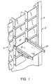
- the system generally comprises a two dimensional array 3 of storage boxes or bins held by suitable frame or compartment means, not shown.
- a platform generally indicated as element 2 and including extractor 20 mounted on a mast thereof Is provided with control means for first causing the platform to move longitudinally to the proper column and then causing the extractor portion to move vertically along its mast 5 to the proper row to access a particular bin 10.
- Any suitable means may be used to control movement of the platform and its extractor, for example and without limitation, the means disclosed in Patent No. 3,490,616.
- extractor 20 is moved vertically along the mast 5 of platform 2 into position opposite bin 10 by the action of the control system, not shown but well known to those skilled in the art.
- bin 10 has two small openings 12 near either end of its side walls. These openings, which are conveniently rectangular in shape for reasons discussed below but which may be of other shapes, provide the means in this embodiment by which the bins are gripped for moving by elements of the extractor 20. Openings 12 are preferably located near the lower edge of the side walls.
- the frame of extractor 20 is made up of side members 32 and end members 30, rigidly attached together. Atop the extractor frame and along each side thereof are positioned the two extending arms 300 of the extractor which move toward and away from bin 10 in a manner to be described. Between the arms, and rigidly connected to them, is a bin support assembly comprising bottom walls 41 and side walls 43, each of which has several plastic glides 45 affixed thereto in spaced relationship. End walls 47 connect the bottom walls and provide rigidity to the support assembly.
- Each arm 300 is made up of identically shaped top and bottom members 34, side members 35 and one or more rear members 36. The front face of each arm is left open, for reasons about to be described.
- Each arm contains two chain drives 42 and 44, mounted on sprockets 46 near a first end of the arm.
- the lower chain 42 on earch arm extends only part way along the arm, to a second sprocket, not shown, where motive power is received from motor 70 through a suitable transmission path.
- a serpentine chain drive beneath extractor 20 transmits power from motor 70 to chains 42.
- Upper chains 44 extend essentially the full length of arms 300, to sprockets 61 and cause the actual movement of the bin engaging means.
- a finger support plate 48 is mounted on guide rails on the support assembly, just in front of the front face of each arm. The orientation of the guide rails permit finger support plate 48 to travel back and forth in front of the arm in a mannerto be described. While not clearly seen in Figure 2, each arm also includes a finger block 50 connected with chain 44 and associated with the support plate 48 in a manner discussed below in connection with Figures 4A, 4B, 4C and 4D.
- motor 80 When extractor 20 has been properly positioned in the vertical and horizontal planes before a bin to be extracted, motor 80 is activated by the control system. As will be seen in Figure 2, motor 80 transmits its power to the bin support assembly through chain 94, whlch operates a bell crank mechanism 95 causing pin 97 to exert lateral force on channel 100, driving the bin support platform and arms 300 toward the bin 10. In this fashion, the bin support assembly and telescoping arms 300 with plates 48 positioned near the ends thereof adjacent to the bin 10 to be extracted are moved toward the bin into the position shown in Figure 3. This operation, whereby the extracting elements are brought into their operative position, is often referred to as indexing.
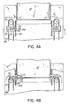
- opening 49 in finger support plate 48 is located adjacent opening 12 in the bin 10. At this point further movement of chain 44 under the action of motor 70 will cause engagement of the bin by finger block 50, as will be described with reference to Figs. 4A, 4B, 4C and 4D.
- finger block 50 is attached to chain 44 by an upstanding pin 52 mounted on chain 44.
- Finger block 50 has two elements. The first of these elements or the front element contains a cavity having an open end which is oriented outwardly, away from the centerline of the extractor and, at the closed end thereof, protruding fingers 51 and 53 which extend inwardly of the inner path of chain 44, in alignment with opening 49 in plate 48.
- the second or rear element of finger block 50 comprises a plunger having pin 52 connected thereto.
- Compression spring 54 is located between the plunger and the closed end of the cavity and is adjusted, together with the various dimensions, so that when the finger block 50 is in the position shown in Fig. 4A, that is, before plate 48 and finger block 50 have moved down along the sides of bin 10, spring 54 is not in compression.
- finger support plate 48 preserves the orientation of finger block 50 by sliding along its guide rails under the influence of finger block 50. Plate 48 therefore guides finger block 50 and simultaneously is moved by it.
- Fig. 4B illustrates the relative position of relevant parts when finger support plate 48 and finger block 50 have been moved to their most extreme extension toward the bin. In this position, finger blocks 50 are being driven inwardly toward each other by the action of chains 44. It will be appreciated that finger support plate 48 fixes the orientation of finger blocks, keeping them aimed inwardly. As will be seen in Fig. 4B, fingers 53 have entered slots 12 in bin 10 from both sides and are pressing inwardly toward each other, thus gripping the bin firmly.
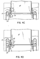
- Figure 4C shows the relative position of the elements when chains 44 and 42 have moved still further in the same direction. Now finger blocks 50 have reached their closest positions relative to each other; compression springs 54 are maximally compressed, and withdrawal force is just being applied to bin 10.
- Figure 4D shows the withdrawal of bin 10 well underway, as finger blocks 50, and of course their associated finger support plates 48 have moved downward away from the storage location of bin 10.
- bin 10 will be fully extracted from the storage location and will be resting entirely on the bin support assembly described in connection with Figure 2. At that point, further movement of chain 44 will bring pin 52 around to the path further from the bin 10, and this will cause withdrawal of the fingers from openings 12.
- motor 70 may be deactivated, and motor 80 will instead be activated to re-index the extractor elements into a neutral position for movement to another location in the array or to another location entirely.
- the distance between sprockets 46 and 61 is preferably made nearly the same as the distance between the openings in the side all of the container, modified to account for the radius of the sprockets.
- bin engaging element has been described as a finger block, and while the bin has been described as having openings in its side walls, with lighter bins the openings may be dispensed with and the finger blocks may be replaced with friction pads.
Landscapes
- Engineering & Computer Science (AREA)
- Mechanical Engineering (AREA)
- Warehouses Or Storage Devices (AREA)
Claims (9)
Applications Claiming Priority (2)
| Application Number | Priority Date | Filing Date | Title |
|---|---|---|---|
| US06/704,552 US4690602A (en) | 1985-02-22 | 1985-02-22 | Automatic storage and retrieval system |
| US704552 | 1985-02-22 |
Publications (2)
| Publication Number | Publication Date |
|---|---|
| EP0192259A1 EP0192259A1 (de) | 1986-08-27 |
| EP0192259B1 true EP0192259B1 (de) | 1988-09-14 |
Family
ID=24829975
Family Applications (1)
| Application Number | Title | Priority Date | Filing Date |
|---|---|---|---|
| EP86102190A Expired EP0192259B1 (de) | 1985-02-22 | 1986-02-20 | Ein- und Ausspeicherungssystem |
Country Status (5)
| Country | Link |
|---|---|
| US (1) | US4690602A (de) |
| EP (1) | EP0192259B1 (de) |
| JP (3) | JP2585524B2 (de) |
| CA (1) | CA1276569C (de) |
| DE (1) | DE3660716D1 (de) |
Cited By (3)
| Publication number | Priority date | Publication date | Assignee | Title |
|---|---|---|---|---|
| DE3790864T1 (de) * | 1986-12-25 | 1988-12-08 | ||
| DE19613707A1 (de) * | 1996-03-26 | 1997-10-02 | Mannesmann Ag | Vorrichtung zur Lastaufnahme oder Lastabgabe |
| DE102012220193A1 (de) | 2012-11-06 | 2014-05-08 | Kardex Produktion Deutschland Gmbh | Lagergut-Extraktor für ein automatisches Lagersystem |
Families Citing this family (55)
| Publication number | Priority date | Publication date | Assignee | Title |
|---|---|---|---|---|
| US4690602A (en) * | 1985-02-22 | 1987-09-01 | Applied Retrieval Technology, Inc. | Automatic storage and retrieval system |
| JPH075166B2 (ja) * | 1987-05-01 | 1995-01-25 | 株式会社イトーキクレビオ | 自動保管検索装置 |
| US4856956A (en) * | 1987-06-18 | 1989-08-15 | Supac Systems, Inc. | Container extraction and transfer mechanism for an automated storage and retrieval system |
| GB2205822A (en) * | 1987-06-18 | 1988-12-21 | Supac Systems Inc | Container extraction and transfer mechanism for an automated storage and retrieval system |
| US5203661A (en) * | 1987-08-05 | 1993-04-20 | Canon Kabushiki Kaisha | Handling device for articles or containers |
| US4896024A (en) * | 1987-10-19 | 1990-01-23 | Diebold, Incorporated | Apparatus for dispensing and accepting return of reusable articles |
| US4812102A (en) * | 1987-10-29 | 1989-03-14 | Jervis B. Webb Company | Storage and retrieval machine for tote pans |
| DE3739158A1 (de) * | 1987-11-19 | 1989-06-01 | Albert Blum | Lagersystem mit einer foerdereinrichtung, insbesondere parksystem fuer fahrzeuge |
| JPH01242302A (ja) * | 1988-03-23 | 1989-09-27 | Motoda Electron Co Ltd | 宅内配設型自動倉庫 |
| EP0427739B1 (de) * | 1988-07-06 | 1995-12-06 | ROTHLISBERGER, Michel | Mechanisiertes lagersystem |
| FR2640944B1 (de) * | 1988-12-28 | 1994-07-13 | A 5 Systemes | |
| US5030055A (en) * | 1989-05-22 | 1991-07-09 | Millard Manufacturing Corp. | Physically integrated manufacturing and materials handling system |
| US5199840A (en) * | 1990-08-01 | 1993-04-06 | John Castaldi | Automated storage and retrieval system |
| EP0493327A1 (de) * | 1990-12-27 | 1992-07-01 | Manitec Consulting AG | Stellplatzregal |
| JPH0549713U (ja) * | 1991-03-29 | 1993-06-29 | 村田機械株式会社 | パッケージ収容装置 |
| WO1993001953A1 (en) * | 1991-07-16 | 1993-02-04 | Gregory William Boland | Article retrieval system and vehicle surveillance system |
| US5328316A (en) * | 1992-08-04 | 1994-07-12 | Hoffmann Christopher J | Automatic storage and retrieval system having an extendible bin extraction mechanism with pop-up tabs |
| US5421697A (en) * | 1993-03-02 | 1995-06-06 | Storage Technology Corporation | Telescopic pick-and-place robotic mechanism |
| DE4422240A1 (de) * | 1993-07-14 | 1995-01-26 | Owl Ag Logistik Systeme Buchs | Verfahren und Einrichtung zur Handhabung von Transportuntersätzen |
| US5362192A (en) * | 1993-09-24 | 1994-11-08 | International Business Machines Corporation | Automated data storage library with single input double gripper mechanism |
| US5499707A (en) * | 1995-01-31 | 1996-03-19 | Compu-Shop, Inc. | Automated merchandising kiosk |
| US5810540A (en) * | 1996-04-30 | 1998-09-22 | Castaldi; John | Automated storage and retrieval system and bin insertion/extraction mechanism therefor |
| US5995459A (en) * | 1996-11-05 | 1999-11-30 | International Data Engineering, Inc. | Flipper mechanism for double-sided media |
| US6619902B1 (en) * | 1997-02-11 | 2003-09-16 | Stein & Associates, P.C. | Automated storage and retrieval system and indexing/insertion extraction mechanism therefor |
| FR2784973B1 (fr) * | 1998-10-27 | 2001-01-19 | Samovie | Appareil d'extraction et de chargement de bacs dans un magasin de stockage |
| US6377526B1 (en) | 1999-04-01 | 2002-04-23 | Plasmon Ide, Inc. | Erasable WORM optical disk and method of writing thereto multiple times |
| US6280135B1 (en) | 1999-05-12 | 2001-08-28 | Greene Line Manufacturing Company | Automated rotary die storage and retrieval unit with complementary rotary die storage rack and complementary rotary die storage cart |
| SE517558C2 (sv) * | 2000-01-12 | 2002-06-18 | Moving Ab | Anordning och lagerautomat för hantering av godsuppbärande element |
| US6416270B1 (en) * | 2000-08-29 | 2002-07-09 | Compu Shop Services, Llc | Automated library kiosk |
| US20020102149A1 (en) * | 2001-01-26 | 2002-08-01 | Tekcel, Inc. | Random access storage and retrieval system for microplates, microplate transport and micorplate conveyor |
| US6923612B2 (en) * | 2002-03-29 | 2005-08-02 | TGW Transportgeräte GmbH & Co. KG | Load-handling system and telescopic arm therefor |
| DE20305123U1 (de) | 2003-03-29 | 2004-04-29 | Megamat GmbH Büro + Lagertechnik | Antriebseinrichtung für eine Lagervorrichtung |
| US7735631B2 (en) * | 2003-09-03 | 2010-06-15 | Siemens Aktiengesellschaft | Mail processing system and method of delivering articles to delivery locations therein |
| US6971837B1 (en) | 2003-12-31 | 2005-12-06 | Honda Motor Co., Ltd. | Stack handling and handwork table |
| ITMO20040236A1 (it) * | 2004-09-17 | 2004-12-17 | System Spa | Magazzino automatico. |
| US7686560B2 (en) * | 2005-12-08 | 2010-03-30 | Conestoga Cold Storage | Rack, conveyor and shuttle automated pick system |
| US10697987B2 (en) | 2006-01-23 | 2020-06-30 | Brooks Automation, Inc. | Automated system for storing, retrieving and managing samples |
| US8251629B2 (en) * | 2007-02-09 | 2012-08-28 | Cerner Innovation, Inc. | Medication dispensing apparatus |
| JP5045208B2 (ja) * | 2007-04-25 | 2012-10-10 | 村田機械株式会社 | 板材搬送システム |
| DE202007011475U1 (de) | 2007-08-14 | 2008-10-02 | Megamat GmbH Büro- und Lagertechnik | Lagervorrichtung |
| EP2165946A1 (de) * | 2008-09-23 | 2010-03-24 | 3M Innovative Properties Company | Automatische Vorrichtung zur Auswahl, Ausgabe und Sammlung von wieder verwendbaren Elementen |
| US10102706B2 (en) * | 2011-08-23 | 2018-10-16 | Vendrx, Inc. | Beneficial product dispenser |
| US8641353B2 (en) * | 2011-08-25 | 2014-02-04 | King Saud University | System for storing and retrieving shoes |
| JP6167923B2 (ja) * | 2014-02-06 | 2017-07-26 | 株式会社ダイフク | 物品搬送設備 |
| DE102015101416A1 (de) * | 2015-01-30 | 2016-08-04 | Hubtex Maschinenbau Gmbh & Co. Kg | Flurförderer und System mit einem Flurförderer |
| JP6930522B2 (ja) * | 2016-02-18 | 2021-09-01 | 株式会社ダイフク | 物品搬送装置 |
| WO2018161100A1 (de) * | 2017-03-07 | 2018-09-13 | Karl Angleitner | Lagerregal für Lagergüter und Regalbedieneinrichtung zum Ein- und Auslagern der Lagergüter |
| CN108706266B (zh) * | 2018-06-11 | 2021-04-20 | 江苏高科物流科技股份有限公司 | 一种穿梭车式自动化仓储及穿梭车系统 |
| DE102019104051A1 (de) * | 2019-02-18 | 2020-08-20 | A&A Logistik-Equipment GmbH & Co. KG | Fahrerloses Transportfahrzeug |
| US11807451B2 (en) * | 2019-09-17 | 2023-11-07 | Hai Robotics Co., Ltd. | Fork and carrying robot |
| CN111137752B (zh) * | 2020-02-04 | 2021-05-04 | 南京新光玻璃钢有限公司 | 一种快递柜辅助取件装置 |
| CN112298890B (zh) * | 2020-11-09 | 2022-08-12 | 北京京东乾石科技有限公司 | 穿梭车 |
| DE102021129337B4 (de) | 2021-11-11 | 2023-09-14 | Fraunhofer-Gesellschaft zur Förderung der angewandten Forschung eingetragener Verein | Lastaufnahmevorrichtung zur Übergabe einer Lagereinheit zwischen einer Regalbedieneinheit und einem Lagerregal und Verfahren |
| CN115027922B (zh) * | 2022-08-10 | 2023-09-22 | 常州富矿智能科技有限公司 | 一种工厂智能化物料运输与仓储系统 |
| CN117622799A (zh) * | 2022-08-19 | 2024-03-01 | 纬联电子科技(中山)有限公司 | 取放设备及搬运机台 |
Family Cites Families (20)
| Publication number | Priority date | Publication date | Assignee | Title |
|---|---|---|---|---|
| US2663434A (en) * | 1949-05-23 | 1953-12-22 | American Mfg Company Inc | Sheet charging apparatus |
| US3490616A (en) * | 1967-11-07 | 1970-01-20 | Supreme Equip & Syst | Storage system with an automatic search and retrieval vehicle with an article guide means thereon |
| FR1562005A (de) * | 1967-12-29 | 1969-04-04 | ||
| JPS4891907A (de) * | 1972-03-08 | 1973-11-29 | ||
| JPS515990B2 (de) * | 1972-03-13 | 1976-02-24 | ||
| US3840131A (en) * | 1972-12-11 | 1974-10-08 | Supreme Equip & Syst | Storage and retrieval system |
| JPS5038079U (de) * | 1973-08-06 | 1975-04-19 | ||
| JPS5039981U (de) * | 1973-08-10 | 1975-04-23 | ||
| US4010855A (en) * | 1975-02-27 | 1977-03-08 | Litton Systems, Inc. | Warehouse system with pan transfer apparatus |
| DE2550323C3 (de) * | 1975-11-08 | 1981-06-04 | Ipsen Industries International Gmbh, 4190 Kleve | Ladegerät zum Behältertransport |
| JPS541752U (de) * | 1977-06-08 | 1979-01-08 | ||
| IT1083139B (it) * | 1977-06-08 | 1985-05-21 | Bertello Ist Grafico | Dispositivo per lo spostamento di contenitori per un complesso di archiviazione meccanizzata |
| IT1166090B (it) * | 1979-04-27 | 1987-04-29 | Istituto Geografico Bertello S | Carrello di manovra a ferni per archivi automatici atto a prelevare e presentare alla consultazione i cassetti indifferentemente su entrambi i lati |
| IT1166132B (it) * | 1979-07-16 | 1987-04-29 | Camerini Mario | Metodo sistema impianto per immagazzinare containers (contenitori metallici standarsizzati) che consente nel contempo economia di spazio, di tempo e disponibilita' immediatata di ogni singolo container, il tutto a comando manuale e/o automatizzato e/o programmato e/o selettivo |
| JPS5619551A (en) * | 1979-07-27 | 1981-02-24 | Motoda Electronics Co Ltd | Automatic reproducing unit of video |
| US4358239A (en) * | 1980-09-26 | 1982-11-09 | Harnischfeger Corporation | Warehouse crane including inclinable tote pan puller |
| US4352622A (en) * | 1980-12-23 | 1982-10-05 | Harnischfeger Corporation | Warehouse crane with pin-engageable tote pans |
| JPS58122669A (ja) * | 1982-01-18 | 1983-07-21 | Hitachi Ltd | デイスク自動装填機構 |
| JPS5936004A (ja) * | 1982-08-18 | 1984-02-28 | Okamura Seisakusho:Kk | 小物品収納用コンテナ取出し装置 |
| US4690602A (en) * | 1985-02-22 | 1987-09-01 | Applied Retrieval Technology, Inc. | Automatic storage and retrieval system |
-
1985
- 1985-02-22 US US06/704,552 patent/US4690602A/en not_active Expired - Fee Related
-
1986
- 1986-02-20 EP EP86102190A patent/EP0192259B1/de not_active Expired
- 1986-02-20 DE DE8686102190T patent/DE3660716D1/de not_active Expired
- 1986-02-21 JP JP61035394A patent/JP2585524B2/ja not_active Expired - Lifetime
- 1986-02-21 CA CA000502455A patent/CA1276569C/en not_active Expired - Lifetime
-
1994
- 1994-03-04 JP JP6034853A patent/JP2644443B2/ja not_active Expired - Lifetime
- 1994-07-26 JP JP6174525A patent/JP2644452B2/ja not_active Expired - Lifetime
Cited By (5)
| Publication number | Priority date | Publication date | Assignee | Title |
|---|---|---|---|---|
| DE3790864T1 (de) * | 1986-12-25 | 1988-12-08 | ||
| DE19613707A1 (de) * | 1996-03-26 | 1997-10-02 | Mannesmann Ag | Vorrichtung zur Lastaufnahme oder Lastabgabe |
| DE19613707C2 (de) * | 1996-03-26 | 2002-11-21 | Siemens Ag | Vorrichtung zur Lastaufnahme oder Lastabgabe |
| DE102012220193A1 (de) | 2012-11-06 | 2014-05-08 | Kardex Produktion Deutschland Gmbh | Lagergut-Extraktor für ein automatisches Lagersystem |
| WO2014072265A1 (de) | 2012-11-06 | 2014-05-15 | Kardex Produktion Deutschland Gmbh | Lagergut-extraktor für ein automatisches lagersystem |
Also Published As
| Publication number | Publication date |
|---|---|
| JP2644452B2 (ja) | 1997-08-25 |
| DE3660716D1 (en) | 1988-10-20 |
| US4690602A (en) | 1987-09-01 |
| JPS61243703A (ja) | 1986-10-30 |
| EP0192259A1 (de) | 1986-08-27 |
| CA1276569C (en) | 1990-11-20 |
| JP2644443B2 (ja) | 1997-08-25 |
| JPH0789604A (ja) | 1995-04-04 |
| JPH07144711A (ja) | 1995-06-06 |
| JP2585524B2 (ja) | 1997-02-26 |
Similar Documents
| Publication | Publication Date | Title |
|---|---|---|
| EP0192259B1 (de) | Ein- und Ausspeicherungssystem | |
| US4756657A (en) | Stacker bin shuttle | |
| US5328316A (en) | Automatic storage and retrieval system having an extendible bin extraction mechanism with pop-up tabs | |
| US5634760A (en) | Inserter/extractor used with carousel of storage bins | |
| US4856956A (en) | Container extraction and transfer mechanism for an automated storage and retrieval system | |
| US4389157A (en) | Retrieval and storage mechanism for use with an automated rotating storage unit | |
| US5544996A (en) | Automated storage and retrieval system | |
| US4592692A (en) | Pallet loading apparatus | |
| AU603046B2 (en) | Mechanised storage system | |
| US4656949A (en) | Device for gripping and transferring load supports or containers using synchronous endless chains with drive fingers, mounted to transversely adjustable modules | |
| EP3133040B1 (de) | Behälteranhebende/-absenkende fördervorrichtung | |
| US4566838A (en) | Accumulator pan transfer device | |
| US4671723A (en) | Apparatus for pushing stacks or packs from a support | |
| CA2949774C (en) | Container raising/lowering conveyance apparatus | |
| US6799938B2 (en) | Commissioning device with vertical product storage units and lower conveyor belt or similar | |
| US5174712A (en) | Apparatus for holding stationary a stack of articles while lifting a sheet by suction from the top of the stack | |
| EP0022441B1 (de) | Automatisches Lager- und Entnahmesystem des Karussell-Typs | |
| US4744205A (en) | Case packing head | |
| GB2266521A (en) | Automatic warehouse | |
| GB2205822A (en) | Container extraction and transfer mechanism for an automated storage and retrieval system | |
| SU1279719A1 (ru) | Способ подачи полосового материала к прессу и устройство дл его осуществлени | |
| CN220843529U (zh) | 一种料盘存储仓及存储仓移料装置 | |
| JP2644443C (de) | ||
| US3812786A (en) | Conveyor apparatus | |
| CA1284622C (en) | Multi-access storage system |
Legal Events
| Date | Code | Title | Description |
|---|---|---|---|
| PUAI | Public reference made under article 153(3) epc to a published international application that has entered the european phase |
Free format text: ORIGINAL CODE: 0009012 |
|
| AK | Designated contracting states |
Kind code of ref document: A1 Designated state(s): DE FR GB IT NL |
|
| 17P | Request for examination filed |
Effective date: 19861007 |
|
| 17Q | First examination report despatched |
Effective date: 19870817 |
|
| GRAA | (expected) grant |
Free format text: ORIGINAL CODE: 0009210 |
|
| AK | Designated contracting states |
Kind code of ref document: B1 Designated state(s): DE FR GB IT NL |
|
| ITF | It: translation for a ep patent filed | ||
| REF | Corresponds to: |
Ref document number: 3660716 Country of ref document: DE Date of ref document: 19881020 |
|
| ET | Fr: translation filed | ||
| PLBE | No opposition filed within time limit |
Free format text: ORIGINAL CODE: 0009261 |
|
| STAA | Information on the status of an ep patent application or granted ep patent |
Free format text: STATUS: NO OPPOSITION FILED WITHIN TIME LIMIT |
|
| 26N | No opposition filed | ||
| ITTA | It: last paid annual fee | ||
| PGFP | Annual fee paid to national office [announced via postgrant information from national office to epo] |
Ref country code: NL Payment date: 19910228 Year of fee payment: 6 |
|
| PG25 | Lapsed in a contracting state [announced via postgrant information from national office to epo] |
Ref country code: NL Effective date: 19920901 |
|
| NLV4 | Nl: lapsed or anulled due to non-payment of the annual fee | ||
| PGFP | Annual fee paid to national office [announced via postgrant information from national office to epo] |
Ref country code: FR Payment date: 19940307 Year of fee payment: 9 |
|
| PGFP | Annual fee paid to national office [announced via postgrant information from national office to epo] |
Ref country code: GB Payment date: 19940309 Year of fee payment: 9 |
|
| PGFP | Annual fee paid to national office [announced via postgrant information from national office to epo] |
Ref country code: DE Payment date: 19940420 Year of fee payment: 9 |
|
| PG25 | Lapsed in a contracting state [announced via postgrant information from national office to epo] |
Ref country code: GB Effective date: 19950220 |
|
| GBPC | Gb: european patent ceased through non-payment of renewal fee |
Effective date: 19950220 |
|
| PG25 | Lapsed in a contracting state [announced via postgrant information from national office to epo] |
Ref country code: FR Effective date: 19951031 |
|
| PG25 | Lapsed in a contracting state [announced via postgrant information from national office to epo] |
Ref country code: DE Effective date: 19951101 |
|
| REG | Reference to a national code |
Ref country code: FR Ref legal event code: ST |
|
| PG25 | Lapsed in a contracting state [announced via postgrant information from national office to epo] |
Ref country code: IT Free format text: LAPSE BECAUSE OF NON-PAYMENT OF DUE FEES;WARNING: LAPSES OF ITALIAN PATENTS WITH EFFECTIVE DATE BEFORE 2007 MAY HAVE OCCURRED AT ANY TIME BEFORE 2007. THE CORRECT EFFECTIVE DATE MAY BE DIFFERENT FROM THE ONE RECORDED. Effective date: 20050220 |