EP0356736B1 - Giessanordnung, Verfahren zur Benutzung der Anordnung, Giessanordnung für Fahrzeugräder, Verfahren zur Benutzung der Anordnung und Fahrzeugräder - Google Patents
Giessanordnung, Verfahren zur Benutzung der Anordnung, Giessanordnung für Fahrzeugräder, Verfahren zur Benutzung der Anordnung und Fahrzeugräder Download PDFInfo
- Publication number
- EP0356736B1 EP0356736B1 EP89114139A EP89114139A EP0356736B1 EP 0356736 B1 EP0356736 B1 EP 0356736B1 EP 89114139 A EP89114139 A EP 89114139A EP 89114139 A EP89114139 A EP 89114139A EP 0356736 B1 EP0356736 B1 EP 0356736B1
- Authority
- EP
- European Patent Office
- Prior art keywords
- casting
- space
- hot melt
- mold
- casting space
- Prior art date
- Legal status (The legal status is an assumption and is not a legal conclusion. Google has not performed a legal analysis and makes no representation as to the accuracy of the status listed.)
- Expired - Lifetime
Links
- 238000005266 casting Methods 0.000 title claims abstract description 108
- 238000000034 method Methods 0.000 title claims abstract description 15
- 239000012943 hotmelt Substances 0.000 claims description 51
- 238000007599 discharging Methods 0.000 claims description 6
- 238000001816 cooling Methods 0.000 abstract description 2
- 230000002349 favourable effect Effects 0.000 description 8
- 238000000465 moulding Methods 0.000 description 4
- 239000012530 fluid Substances 0.000 description 3
- 238000005192 partition Methods 0.000 description 3
- 238000004891 communication Methods 0.000 description 2
- 230000007547 defect Effects 0.000 description 1
- 238000007493 shaping process Methods 0.000 description 1
Images

Classifications
-
- B—PERFORMING OPERATIONS; TRANSPORTING
- B22—CASTING; POWDER METALLURGY
- B22D—CASTING OF METALS; CASTING OF OTHER SUBSTANCES BY THE SAME PROCESSES OR DEVICES
- B22D47/00—Casting plants
-
- B—PERFORMING OPERATIONS; TRANSPORTING
- B22—CASTING; POWDER METALLURGY
- B22D—CASTING OF METALS; CASTING OF OTHER SUBSTANCES BY THE SAME PROCESSES OR DEVICES
- B22D15/00—Casting using a mould or core of which a part significant to the process is of high thermal conductivity, e.g. chill casting; Moulds or accessories specially adapted therefor
- B22D15/005—Casting using a mould or core of which a part significant to the process is of high thermal conductivity, e.g. chill casting; Moulds or accessories specially adapted therefor of rolls, wheels or the like
-
- B—PERFORMING OPERATIONS; TRANSPORTING
- B22—CASTING; POWDER METALLURGY
- B22C—FOUNDRY MOULDING
- B22C9/00—Moulds or cores; Moulding processes
- B22C9/22—Moulds for peculiarly-shaped castings
- B22C9/28—Moulds for peculiarly-shaped castings for wheels, rolls, or rollers
Definitions
- This invention relates to a casting device having a mold provided with a main body and a casting space, and to a method for using the device.
- a mold temperature is set sufficiently high in order to obtain a favorable run of a hot melt.
- This conventional casting device has such disadvantages as that as the mold temperature is set sufficiently high, it takes a long time for the hot melt to be hardened, and as a result, the casting structure of the casting does not become dense, and therefore, a high strength is difficult to obtain.
- a main body of a mold is provided at its lower part with a weir and a hot melt is poured into a casting space through this weir (Japanese Patent Early Laid-open Publication No. Sho 55-120465).
- this conventional casting device has such disadvantages as that as the cooling device is disposed at a lower part of the main body of the mold, it is difficult to maintain the hot melt in a constant level of temperature, and as a result, a casting defect tends to occur.
- the present invention has been accomplished in order to overcome the above-mentioned disadvantages of the prior art.
- vent hole opening into the casting space being provided with air discharging means for discharging air from the casting space and further being provided with feeding means for feeding the casting space with presurized air through the vent hole.
- the device may be provided with an auxiliary space arranged at the upper part of the casting space and communicating with the casting space.
- An inlet hole can be provided for introducing presurized air into the auxiliary space.
- a marking means for casting a mark on the casting structure On a portion of a wall of the casting space might be provided with a marking means for casting a mark on the casting structure and between the auxiliary space and the casting space may be disposed a border surface in the vicinity of the marking means. With this arrangement it is possible to print clear casting marks, even if the casting mark is tiny.
- the object of the invention can also be achieved by a method for using the casting device.
- the method consists in pouring a hot melt into the casting space of the mold and flowing pressurized air into the vent hole after the hot melt reaches the vent hole which communicates with the casting space.
- the casting device and the method for using the device according to the invention can be used for casting vehicle wheels.
- the casting space is used for molding the disk of the wheel.
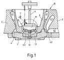
- M denotes a mold for molding a vehicle wheel.
- the mold 1 comprises a combination of a lower mold 1, a horizontal mold 2 and an upper mold 3.
- This mold M has a casting space 4 having the shape of a vehicle wheel.
- 11 denotes a first nest of the lower mold 1 and is secured to a central portion of the lower mold 1 by a bolt 12. With this first nest 11 an outer surface of a hub portion (of the vehicle wheel) is shaped.
- a second nest 111 of the lower mold 1 is secured to the outer surface of the first nest 11 also by the bolt 12.
- This nest 111 is for shaping an axle hole of the vehicle wheel.
- Nest 31 of the upper mold 3 is engaged with a central portion of the upper mold 3. This nest 31 shapes a rear surface of the hub portion of the vehicle wheel.
- 41 denotes a feeding head space
- 42 denotes a hot melt passage communicated with the casting space 4
- 43 denotes a gate formed at the hot melt passage 42.
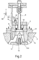
- the nest 31 of the upper mold 3 is open at its upper end, with which a vent barrel 5 is engaged.
- 6 denotes an extruding pin which is reciprocally movably inserted through the central portion of the vent barrel 5.
- a partition wall 51 is integrated in the vent barrel 5. Underneath of the partition wall 51 of the vent barrel 5 is a vent room or auxiliary space 7.
- 54 denotes a contact surface between the vent barrel 5 and the nest 31 of the upper mold 3 enclosing a small gap as a communicating passage of this invention. Through this communicating passage at the contact surface 54, the casting space 4 and the auxiliary space 7 are communicated with atmosphere.
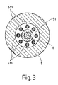
- 511 designates vent holes formed in the partition wall 51.
- 52 denotes a lid member which covers the opening at the upper end of the vent barrel 5.
- the lid member 52 is formed with a pressurized air inlet hole 53.
- 8 denotes a connecting piece engaged with the inlet hole 53.
- 81 denotes a gas pipe connected with the connecting piece 8.
- the hot melt moves upward within the casting space 4. At this time, air within the casting space 4 is discharged into atmosphere through the communication passage at the contact surface 54. And, when the hot melt reaches the border line A between the casting space 4 and the auxiliary space 7, the gap or communication passage of the contact surface 54 is blocked with the hot melt. Therefore, air within the auxiliary space 7 can not discharge. As a result, the temperature of the hot melt will not raise. Therefore, the interior of the auxiliary space 7 is secured as a pressur space.
- the feeding valve 82 of the gas pipe 81 is opened to feed the pressurized air into the auxiliary space 7 to raise the internal pressure of the auxiliary space 7. Then, the surface A of the hot melt now reaching the lower end portion of the auxiliary space 7 is pressurized. As a result, the hot melt enters easily into every corner of the auxiliary space 7.
- gas within the casting space can be discharged and a pressurized fluid can be fed in the direction of the casting space through the vent hole.
- this casting device in the case that this casting device is used, a favorable run of a hot melt can be maintained without raising the temperature of the mold. Therefore, there can be obtained a casting structure of high density and a casting of high strength.
- the surface of the hot melt within the casting space can be pressurized through the vent hole after the hot melt is poured. Accordingly, a favorable run of a hot melt can be enhanced.
- the casting device may be used for casting a vehicle wheel.
- Gas within the casting space 4 for forming the disk of the wheel can be discharged and a pressurized fluid can be fed in the direction of the disk forming casting space through the vent hole 511. Further, the surface of the hot melt within the casting space for the disk can be pressurized through the vent hole after the hot melt is poured. Accordingly, a favorable run of a hot melt can be enhanced.
- the A communicating passage disposed on the border line A between the casting space 4 and the auxiliary space 7 in the mold so that the auxiliary space is communicated with atmosphere through this communicating passage.
- this casting device in the case that this casting device is used, a favorable run of a hot melt can be maintained without raising the temperature of the mold. Therefore, there can be obtained a casting of high density casting structure and of high strength.
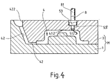
- M denotes a mold for molding a wheel cap C which comprises a combination of a lower mold 1 and an upper mold 3.
- This mold M has a wheel cap-shaped molding space 4.
- a hot melt port 422 and a hot melt passage 42 are formed in the upper mold 3 on a border surface between the upper mold 3 and the lower mold 1. This hot melt passage 42 is continuous to the hot melt port 422 and opens into the casting space 4.
- a marking means 412 for casting a mark on the wheel is formed on an upper wall surface of the casting space 4.
- This casting mark means 412 is designed as such that a mark of "ABC" is printed out on the surface of the wheel cap C (Fig. 5).
- An air vent or vent holes 512 are mounted on an opening end of the auxiliary space 55. This air vent 512 is adapted to prevent the hot melt from entering into the auxiliary space 55.
- 53 denotes an inlet hole for pressurized fluid formed in the upper mold 3.
- This inlet hole 53 is communicated with an upper end portion of the auxiliary space 55.
- 8 denotes a connecting pipe inserted in the inlet hole 53. Through this connecting pipe 8, the inlet hole 53 and the gas pipe 81 are connected with each other.
- a hot melt is poured into the casting space 4 through the hot melt port 422 and the hot melt passage 42.
- a pressurized gas is fed into the auxiliary space 55 through the inlet hole 53 to raise the internal pressure of the auxiliary space 51.
- the surface S of the hot melt which now reaches the lower end portion of the auxiliary space 55 is pressurized.
- the hot melt in the vicinity of the auxiliary space 55 is strongly pressed against the wall surface of the casting space 4, the hot melt is also strongly pressed against the casting mark means 412. As a result, a casting mark is clearly formed thereon.
- the marking means is such constructed as mentioned above, when a pressurized gas is introduced into the auxiliary space after the hot melt is poured into the casting space, the internal pressure of the auxiliary space pressurizes the surface of the hot melt (the border surface with respect to the auxiliary space). As a result, as the hot melt in the vicinity of the auxiliary space is strongly pressed against the wall surface of the casting space, the hot melt is also strongly pushed against the mark forming portion.
Landscapes
- Engineering & Computer Science (AREA)
- Mechanical Engineering (AREA)
- Molds, Cores, And Manufacturing Methods Thereof (AREA)
- Body Structure For Vehicles (AREA)
- Vehicle Body Suspensions (AREA)
Claims (5)
- Gießvorrichtung mit einer Form (M), die ein Formgehäuse (1,2,3) und eine Formkammer (4) einschließt, dadurch gekennzeichnet, daß in die Formkammer (4) eine Entlüftungsöffnung (511) mündet, die mit einem Luftaustrittsmittel zur Entlüftung der Formkammer und mit einem Zuführungsmittel (81,82) zur Zuführung von Druckluft in die Formkammer (4) durch die Entlüftungsöffnung (511) versehen ist.
- Vorrichtung nach Anspruch 1, bei der im oberen Bereich der Formkammer (4) eine Hilfskammer (7,55) angeordnet ist, die mit der Formkammer (4) in Verbindung steht, wobei die Form ferner mit einer Einlaßöffnung (53) versehen ist, um Druckluft in die Hilfskammer einführen zu können.
- Vorrichtung nach Anspruch 2, bei der diese Vorrichtung ferner ein Markierungsmittel (412) zum Formen einer Markierung beim Gießen einschließt, wobei das Markierungsmittel auf einem Teil einer Wand der Formkammer (4) der Form (M) angeordnet ist, wobei ferner eine Grenzfläche zwischen der Hilfskammer (55) und der Formkammer (4) in der Nähe des Wandteils mit dem Markierungsmittel vorgesehen ist.
- Verfahren zur Verwendung einer Gießvorrichtung mit einer Form (M) mit einer Gießkammer (4) und einer Entlüftungsöffnung (511,512) in Verbindung mit der Gießkammer nach Anspruch 1, gekennzeichnet durch Einbringen einer heißen Schmelze in die Gießkammer (4) der Form (M) und das Einbringen von Druckluft in die Entlüftungsöffnung (511,512), nachdem die heiße Schmelze die Entlüftungsöffnung erreicht hat.
- Verwendung einer Gießvorrichtung und eines Verfahrens nach der Ansprüchen 1 bis 4 zur Herstellung von Fahrzeugrädern.
Priority Applications (1)
| Application Number | Priority Date | Filing Date | Title |
|---|---|---|---|
| EP96105707A EP0722795B1 (de) | 1988-07-31 | 1989-07-31 | Verfahren und Vorrichtung zum Giessen von Fahrzeugrädern |
Applications Claiming Priority (24)
| Application Number | Priority Date | Filing Date | Title |
|---|---|---|---|
| JP63191447A JPH0241733A (ja) | 1988-07-31 | 1988-07-31 | 鋳造用鋳出し装置 |
| JP19144688A JP2598974B2 (ja) | 1988-07-31 | 1988-07-31 | 鋳造装置 |
| JP191454/88 | 1988-07-31 | ||
| JP63191453A JPH0241734A (ja) | 1988-07-31 | 1988-07-31 | 車両用ホイールの鋳型 |
| JP63191448A JP2729488B2 (ja) | 1988-07-31 | 1988-07-31 | 車両用ホイールの鋳造装置 |
| JP191448/88 | 1988-07-31 | ||
| JP63191454A JPH0241735A (ja) | 1988-07-31 | 1988-07-31 | 車両用ホイールの鋳造方法およびその鋳型 |
| JP191445/88 | 1988-07-31 | ||
| JP63191445A JPH0241754A (ja) | 1988-07-31 | 1988-07-31 | 鋳造装置およびその装置を使用する方法 |
| JP191453/88 | 1988-07-31 | ||
| JP191446/88 | 1988-07-31 | ||
| JP191447/88 | 1988-07-31 | ||
| JP302107/88 | 1988-11-29 | ||
| JP63302107A JP2817925B2 (ja) | 1988-11-29 | 1988-11-29 | アルミニウム合金製車両用ホイール |
| JP63304880A JPH02151344A (ja) | 1988-11-30 | 1988-11-30 | 車両用ホイールの鋳造装置 |
| JP304880/88 | 1988-11-30 | ||
| JP1196381A JPH0360857A (ja) | 1989-07-27 | 1989-07-27 | 車両用ホイールの鋳造装置 |
| JP1196378A JPH0360855A (ja) | 1989-07-27 | 1989-07-27 | 車両用ホイールの鋳造装置 |
| JP1196380A JP2794002B2 (ja) | 1989-07-27 | 1989-07-27 | 鋳型装置 |
| JP196380/89 | 1989-07-27 | ||
| JP196379/89 | 1989-07-27 | ||
| JP196378/89 | 1989-07-27 | ||
| JP1196379A JPH0360856A (ja) | 1989-07-27 | 1989-07-27 | 車両用ホイールの鋳造装置 |
| JP196381/89 | 1989-07-27 |
Related Child Applications (2)
| Application Number | Title | Priority Date | Filing Date |
|---|---|---|---|
| EP96105707A Division EP0722795B1 (de) | 1988-07-31 | 1989-07-31 | Verfahren und Vorrichtung zum Giessen von Fahrzeugrädern |
| EP96105707.2 Division-Into | 1989-07-31 |
Publications (3)
| Publication Number | Publication Date |
|---|---|
| EP0356736A2 EP0356736A2 (de) | 1990-03-07 |
| EP0356736A3 EP0356736A3 (de) | 1991-03-27 |
| EP0356736B1 true EP0356736B1 (de) | 1996-11-06 |
Family
ID=27583487
Family Applications (2)
| Application Number | Title | Priority Date | Filing Date |
|---|---|---|---|
| EP89114139A Expired - Lifetime EP0356736B1 (de) | 1988-07-31 | 1989-07-31 | Giessanordnung, Verfahren zur Benutzung der Anordnung, Giessanordnung für Fahrzeugräder, Verfahren zur Benutzung der Anordnung und Fahrzeugräder |
| EP96105707A Expired - Lifetime EP0722795B1 (de) | 1988-07-31 | 1989-07-31 | Verfahren und Vorrichtung zum Giessen von Fahrzeugrädern |
Family Applications After (1)
| Application Number | Title | Priority Date | Filing Date |
|---|---|---|---|
| EP96105707A Expired - Lifetime EP0722795B1 (de) | 1988-07-31 | 1989-07-31 | Verfahren und Vorrichtung zum Giessen von Fahrzeugrädern |
Country Status (6)
| Country | Link |
|---|---|
| US (2) | US5320160A (de) |
| EP (2) | EP0356736B1 (de) |
| KR (1) | KR930002519B1 (de) |
| AT (1) | ATE144928T1 (de) |
| AU (1) | AU628831B2 (de) |
| DE (2) | DE68927427T2 (de) |
Cited By (2)
| Publication number | Priority date | Publication date | Assignee | Title |
|---|---|---|---|---|
| CN106180594A (zh) * | 2016-09-08 | 2016-12-07 | 泉州惠安博派信息技术有限公司 | 一种安全化制动轮铸造模具 |
| CN108526427A (zh) * | 2018-03-29 | 2018-09-14 | 泗阳敏于行精密机械有限公司 | 一种低能耗的铝合金轮毂铸旋工艺 |
Families Citing this family (31)
| Publication number | Priority date | Publication date | Assignee | Title |
|---|---|---|---|---|
| GB2250226B (en) * | 1990-11-29 | 1994-08-31 | Honda Motor Co Ltd | Metallic mould for casting vehicle wheel |
| AU7928394A (en) * | 1993-10-07 | 1995-05-01 | Hayes Wheels International, Inc. | Method and apparatus for controlled directional solidification of a wheel casting |
| DE19533447C1 (de) * | 1995-09-09 | 1996-12-05 | Bbs Kraftfahrzeugtechnik | Verfahren und Vorrichtung zum Befüllen eines Gießwerkzeugs mit einer Metallschmelze |
| AU7148598A (en) * | 1997-04-21 | 1998-11-13 | Hayes Lemmerz International, Inc. | Cast wheel having circumferential lightener pockets |
| DE19754959C2 (de) * | 1997-12-11 | 2001-05-17 | Porsche Ag | Rad für ein Kraftfahrzeug mit Hohlspeichen |
| US6463994B1 (en) * | 1998-12-28 | 2002-10-15 | Hayes Lemmerz International, Inc. | Apparatus and method for gravity casting a motorcycle wheel |
| US6443215B1 (en) * | 1998-12-31 | 2002-09-03 | Hayes Lemmerz International, Inc. | Vehicle wheel mold with a retractable ball cap |
| DE19926575C2 (de) * | 1999-06-11 | 2003-04-17 | Porsche Ag | Rad für ein Kraftfahrzeug |
| EP1189765B1 (de) * | 1999-06-11 | 2003-04-09 | Dr.Ing. h.c.F. Porsche Aktiengesellschaft | Rad für ein kraftfahrzeug |
| US6401797B1 (en) | 1999-12-22 | 2002-06-11 | Hayes Lammerz International, Inc. | Mold and method for casting a vehicle wheel |
| AT409728B (de) * | 2000-03-09 | 2002-10-25 | Austria Alu Guss Ges M B H | Verfahren zum herstellen einer rad-gussfelge und giesswerkzeug hierfür |
| JP2002205501A (ja) * | 2001-01-11 | 2002-07-23 | Hitachi Metals Ltd | 車両用軽合金ホイール |
| ITPD20010208A1 (it) * | 2001-08-28 | 2003-02-28 | Bbs Riva Spa | Struttura di stampo particolarmente per cerchi di veicoli stradali |
| KR100469754B1 (ko) * | 2002-08-31 | 2005-02-02 | 케이.엠.에프 주식회사 | 직접방사 필라멘트를 사용한 스웨드조 극세사 편직물의제조방법 |
| US20090065170A1 (en) * | 2007-09-11 | 2009-03-12 | Honda Motor Co., Ltd. | Die cooling apparatus and method thereof |
| US20090266455A1 (en) * | 2008-04-24 | 2009-10-29 | Guido Baggioli | Mold and process for manufacturing toothed sprockets for locking winding rollers of safety belts |
| US9366181B2 (en) | 2009-07-20 | 2016-06-14 | Borgwarner Inc. | Turbocharger and compressor wheel therefor |
| CN101716652B (zh) * | 2009-11-27 | 2011-08-31 | 宁夏共享集团有限责任公司 | 一种矿山机械机架铸件的铸造方法 |
| US8942462B2 (en) * | 2012-04-12 | 2015-01-27 | GM Global Technology Operations LLC | Method for automatic quantification of dendrite arm spacing in dendritic microstructures |
| CN102921862B (zh) * | 2012-10-09 | 2014-10-15 | 西安交通大学 | 一种汽车轮毂整体锻造的连铸连锻模具 |
| CN103878320A (zh) * | 2012-12-21 | 2014-06-25 | 南通太和机械集团有限公司 | 一种凹形铸造模具 |
| CN103817315A (zh) * | 2014-02-25 | 2014-05-28 | 昆山众异特机械工业有限公司 | 一种风水混合冷却系统 |
| CN104525873B (zh) * | 2014-12-15 | 2016-11-02 | 安徽汇联机械工业有限公司 | 一种轮毂模具 |
| CN104550876B (zh) * | 2015-01-05 | 2016-05-04 | 江苏苏美达车轮有限公司 | 一种汽车轮毂增压铸造设备及铸造方法 |
| CN105081299B (zh) * | 2015-09-07 | 2017-03-22 | 浙江今飞凯达轮毂股份有限公司 | 蓄热式低压铸造保温炉 |
| CN105880525A (zh) * | 2016-06-15 | 2016-08-24 | 中信戴卡股份有限公司 | 一种铝合金车轮低压铸造模具 |
| CN106180646A (zh) * | 2016-08-31 | 2016-12-07 | 无锡戴卡轮毂制造有限公司 | 一种水雾冷却低压铸造铝合金轮毂模具的方法 |
| CN106424645A (zh) * | 2016-10-17 | 2017-02-22 | 滁州市银田科技有限公司 | 一种双轴冰箱铰链压铸模具 |
| CN106734967B (zh) * | 2017-01-03 | 2019-03-26 | 浙江六和轻机械有限公司 | 一种能够消除铝合金轮毂铸造针孔的模具 |
| JP7594953B2 (ja) * | 2021-03-25 | 2024-12-05 | 本田技研工業株式会社 | 遮断弁用のキャップ部材、遮断弁用の弁体、遮断弁の製造方法、および遮断弁の弁体の交換方法 |
| CN116037896B (zh) * | 2023-01-10 | 2025-12-05 | 广州驭风旭铝铸件有限公司 | 一种轮毂铸造模具及轮毂铸造冷却工艺 |
Family Cites Families (38)
| Publication number | Priority date | Publication date | Assignee | Title |
|---|---|---|---|---|
| US401804A (en) * | 1889-04-23 | Metallic mold | ||
| US728956A (en) * | 1902-08-11 | 1903-05-26 | Daniel Eagan | Art of casting steel car-wheels. |
| US1015362A (en) * | 1911-01-24 | 1912-01-23 | Griffin Wheel Co | Car-wheel mold and method of making car-wheels. |
| US2004335A (en) * | 1929-03-30 | 1935-06-11 | Michael W Merriman | Manhole frame and cover |
| US1908740A (en) * | 1929-07-06 | 1933-05-16 | Southern Wheel Company | Car wheel and process of making same |
| US1983177A (en) * | 1933-01-16 | 1934-12-04 | Arthur L Lee | Mine car wheel |
| US2420003A (en) * | 1942-09-14 | 1947-05-06 | Miller Engineering Corp | Temperature control mold |
| US2568428A (en) * | 1949-09-09 | 1951-09-18 | Irvin A Billiar | Mold with riser and exothermic insert |
| US2669769A (en) * | 1949-09-10 | 1954-02-23 | Edwin F Peterson | Method of making core box vent plugs |
| DE1249462B (de) * | 1955-09-14 | 1967-09-07 | ||
| US3566952A (en) * | 1967-10-26 | 1971-03-02 | Wyman Curtis Lane | Pressure feeding of casting using a feeder head |
| US3656539A (en) * | 1969-01-29 | 1972-04-18 | Amsted Ind Inc | Apparatus for casting molten metal |
| US3856360A (en) * | 1970-10-30 | 1974-12-24 | Us Reduction Co | Aluminum base alloy die casting wheel |
| FR2287294A1 (fr) * | 1974-10-09 | 1976-05-07 | Peugeot & Renault | Perfectionnement a la coulee de pieces de fonderie en basse pression |
| US4165131A (en) * | 1975-11-05 | 1979-08-21 | Gkn Kent Alloys Limited | Cast vehicle wheels |
| FR2340156A2 (fr) * | 1976-02-03 | 1977-09-02 | Pechiney Aluminium | Procede et dispositif de moulage sous basse pression |
| IT1070235B (it) * | 1976-02-04 | 1985-03-29 | Fata Spa Ora Fata Europ Group | Dispositivo di colata in conchiglia a bassa pressione di pezzi di lega leggera |
| IT1065981B (it) * | 1976-02-04 | 1985-03-04 | Fata S P A Ora Fata Europ Grou | Procedimento ed apparecchiatura per la colata in conchiglia a bassa pressione di pezzi di lega leggera |
| JPS5373426A (en) * | 1976-12-14 | 1978-06-29 | Honda Motor Co Ltd | Casting method |
| GB1587909A (en) * | 1978-01-24 | 1981-04-15 | Pereira J A T | Furnace pressurisation of a low pressure die-casting machine |
| SU725796A1 (ru) * | 1978-08-21 | 1980-04-05 | Научно-Исследовательский Институт Специальных Способов Литья | Кокиль |
| US4606396A (en) * | 1978-10-02 | 1986-08-19 | Hitchiner Manufacturing Co., Inc. | Sand mold and apparatus for reduced pressure casting |
| US4771818A (en) * | 1979-12-14 | 1988-09-20 | Alumax Inc. | Process of shaping a metal alloy product |
| CA1163416A (en) * | 1981-01-26 | 1984-03-13 | Dbm Industries Limited | Die vent for mold cavities |
| JPS5881548A (ja) * | 1981-11-11 | 1983-05-16 | Topy Ind Ltd | ホイ−ルの低圧金型鋳造法 |
| DE3247129A1 (de) * | 1982-12-20 | 1984-06-20 | Institut po Metalosnanie i Technologia na Metalite, Sofija | Giessform |
| JPS59144564A (ja) * | 1983-02-09 | 1984-08-18 | Hitachi Metals Ltd | 鋳造方法およびその装置 |
| JPS61180659A (ja) * | 1985-02-04 | 1986-08-13 | Mazda Motor Corp | 高圧凝固鋳造方法 |
| JPS62118943A (ja) * | 1985-11-19 | 1987-05-30 | Honda Motor Co Ltd | 鋳造金型 |
| JPS62183955A (ja) * | 1986-02-07 | 1987-08-12 | Enbishi Arumihoiile Kk | 低圧鋳造機 |
| DE3619525C1 (en) * | 1986-06-10 | 1987-08-06 | Alulahn Giesserei Gmbh & Co Kg | Method and apparatus for the production of castings, for example motor vehicle wheels, from aluminium, magnesium and similar light metals in low-pressure casting machines |
| JPS6372465A (ja) * | 1986-09-11 | 1988-04-02 | Honda Motor Co Ltd | 鋳型構造 |
| GB8624741D0 (en) * | 1986-10-15 | 1986-11-19 | Hinchcliffe R | Light alloy castings |
| JPH0763832B2 (ja) * | 1987-03-31 | 1995-07-12 | 本田技研工業株式会社 | 鋳造装置 |
| JPS63281745A (ja) * | 1987-05-15 | 1988-11-18 | Kobe Steel Ltd | 金型鋳造における鋳型 |
| FR2616363B1 (fr) * | 1987-06-11 | 1991-04-19 | Cegedur | Procede et dispositif de moulage en sable de pieces composites a matrice en alliage leger et insert fibreux |
| JPH0241751A (ja) * | 1988-07-31 | 1990-02-09 | Asahi Tec Corp | 車両用ホイールの鋳造装置 |
| JPH0241752A (ja) * | 1988-07-31 | 1990-02-09 | Asahi Tec Corp | 車両用ホイールの鋳造装置およびこの装置の使用方法 |
-
1989
- 1989-07-31 EP EP89114139A patent/EP0356736B1/de not_active Expired - Lifetime
- 1989-07-31 AU AU39117/89A patent/AU628831B2/en not_active Ceased
- 1989-07-31 AT AT89114139T patent/ATE144928T1/de not_active IP Right Cessation
- 1989-07-31 KR KR1019890010882A patent/KR930002519B1/ko not_active Expired - Fee Related
- 1989-07-31 DE DE68927427T patent/DE68927427T2/de not_active Expired - Lifetime
- 1989-07-31 DE DE68928866T patent/DE68928866T2/de not_active Expired - Lifetime
- 1989-07-31 EP EP96105707A patent/EP0722795B1/de not_active Expired - Lifetime
-
1992
- 1992-02-21 US US07/840,645 patent/US5320160A/en not_active Expired - Lifetime
-
1994
- 1994-07-05 US US08/271,211 patent/US5527101A/en not_active Expired - Lifetime
Cited By (3)
| Publication number | Priority date | Publication date | Assignee | Title |
|---|---|---|---|---|
| CN106180594A (zh) * | 2016-09-08 | 2016-12-07 | 泉州惠安博派信息技术有限公司 | 一种安全化制动轮铸造模具 |
| CN106180594B (zh) * | 2016-09-08 | 2018-03-16 | 泉州有刺电子商务有限责任公司 | 一种安全化制动轮铸造模具 |
| CN108526427A (zh) * | 2018-03-29 | 2018-09-14 | 泗阳敏于行精密机械有限公司 | 一种低能耗的铝合金轮毂铸旋工艺 |
Also Published As
| Publication number | Publication date |
|---|---|
| EP0722795A3 (de) | 1996-07-31 |
| DE68927427D1 (de) | 1996-12-12 |
| EP0722795B1 (de) | 1998-11-25 |
| AU3911789A (en) | 1990-02-01 |
| EP0356736A2 (de) | 1990-03-07 |
| EP0356736A3 (de) | 1991-03-27 |
| AU628831B2 (en) | 1992-09-24 |
| DE68928866D1 (de) | 1999-01-07 |
| KR930002519B1 (ko) | 1993-04-03 |
| ATE144928T1 (de) | 1996-11-15 |
| US5320160A (en) | 1994-06-14 |
| DE68928866T2 (de) | 1999-08-05 |
| DE68927427T2 (de) | 1997-06-12 |
| KR910002545A (ko) | 1991-02-25 |
| EP0722795A2 (de) | 1996-07-24 |
| US5527101A (en) | 1996-06-18 |
Similar Documents
| Publication | Publication Date | Title |
|---|---|---|
| EP0356736A2 (de) | Giessanordnung, Verfahren zur Benutzung der Anordnung, Giessanordnung für Fahrzeugräder, Verfahren zur Benutzung der Anordnung und Fahrzeugräder | |
| EP0225040B1 (de) | Giessform und Kernzusammensetzung für das Unterdruckgiessverfahren | |
| EP0778096A2 (de) | Pumpengehäuse und Verfahren zu seiner Herstellung | |
| US20040134636A1 (en) | Mold for casting | |
| EP0760267B1 (de) | Niederdruckgiessanlage für Fahrzeugräder | |
| CN218926149U (zh) | 齿轮箱壳体的铸造模具 | |
| EP0554448B1 (de) | Deckel zur aufnahme eines luftsacks | |
| EP0083657B1 (de) | Giessform und konstruktion ihres entlüfters | |
| WO2004004945A1 (ja) | ダイカスト用金型 | |
| US5336078A (en) | Injection mold having a vented core | |
| JP2598974B2 (ja) | 鋳造装置 | |
| CA1337234C (en) | Casting device, method for using the device, casting device of vehicle wheel, method for using the device, and vehicle wheel | |
| CN223762108U (zh) | 气缸端盖压铸模 | |
| CN224101781U (zh) | 一种空气弹簧上气室的铸造模具 | |
| JP3215867B2 (ja) | 車両用ホイールにおける鋳型用冷却装置 | |
| JP3272482B2 (ja) | 射出成形金型におけるガス抜き構造 | |
| CN223544053U (zh) | 一种制动盘铸造模具 | |
| JP3610940B2 (ja) | 鋳型造形用金型及び鋳型造形用金型のエア抜きブロック | |
| JP2000202870A (ja) | 射出成形用金型 | |
| JPS6174765A (ja) | 金型鋳造法 | |
| JPH0641710Y2 (ja) | ガス抜き機構を備えた金型装置 | |
| SU1637948A1 (ru) | Пресс-форма дл лить с противодавлением | |
| JPS63816U (de) | ||
| JPS6010822Y2 (ja) | 合成樹脂の発泡成形用型 | |
| JPH043704Y2 (de) |
Legal Events
| Date | Code | Title | Description |
|---|---|---|---|
| PUAI | Public reference made under article 153(3) epc to a published international application that has entered the european phase |
Free format text: ORIGINAL CODE: 0009012 |
|
| AK | Designated contracting states |
Kind code of ref document: A2 Designated state(s): AT BE CH DE FR GB IT LI LU NL SE |
|
| PUAL | Search report despatched |
Free format text: ORIGINAL CODE: 0009013 |
|
| AK | Designated contracting states |
Kind code of ref document: A3 Designated state(s): AT BE CH DE FR GB IT LI LU NL SE |
|
| 17P | Request for examination filed |
Effective date: 19910920 |
|
| 17Q | First examination report despatched |
Effective date: 19930917 |
|
| GRAG | Despatch of communication of intention to grant |
Free format text: ORIGINAL CODE: EPIDOS AGRA |
|
| GRAH | Despatch of communication of intention to grant a patent |
Free format text: ORIGINAL CODE: EPIDOS IGRA |
|
| GRAH | Despatch of communication of intention to grant a patent |
Free format text: ORIGINAL CODE: EPIDOS IGRA |
|
| GRAA | (expected) grant |
Free format text: ORIGINAL CODE: 0009210 |
|
| RAP1 | Party data changed (applicant data changed or rights of an application transferred) |
Owner name: ASAHI TEC CORPORATION |
|
| AK | Designated contracting states |
Kind code of ref document: B1 Designated state(s): AT BE CH DE FR GB IT LI LU NL SE |
|
| DX | Miscellaneous (deleted) | ||
| PG25 | Lapsed in a contracting state [announced via postgrant information from national office to epo] |
Ref country code: IT Free format text: LAPSE BECAUSE OF FAILURE TO SUBMIT A TRANSLATION OF THE DESCRIPTION OR TO PAY THE FEE WITHIN THE PRE;WARNING: LAPSES OF ITALIAN PATENTS WITH EFFECTIVE DATE BEFORE 2007 MAY HAVE OCCURRED AT ANY TIME BEFORE 2007. THE CORRECT EFFECTIVE DATE MAY BE DIFFERENT FROM THE ONE RECORDED.SCRIBED TIME-LIMIT Effective date: 19961106 Ref country code: BE Effective date: 19961106 Ref country code: LI Effective date: 19961106 Ref country code: NL Free format text: LAPSE BECAUSE OF FAILURE TO SUBMIT A TRANSLATION OF THE DESCRIPTION OR TO PAY THE FEE WITHIN THE PRESCRIBED TIME-LIMIT Effective date: 19961106 Ref country code: CH Effective date: 19961106 Ref country code: AT Effective date: 19961106 Ref country code: FR Effective date: 19961106 |
|
| REF | Corresponds to: |
Ref document number: 144928 Country of ref document: AT Date of ref document: 19961115 Kind code of ref document: T |
|
| REF | Corresponds to: |
Ref document number: 68927427 Country of ref document: DE Date of ref document: 19961212 |
|
| PG25 | Lapsed in a contracting state [announced via postgrant information from national office to epo] |
Ref country code: SE Effective date: 19970206 |
|
| NLV1 | Nl: lapsed or annulled due to failure to fulfill the requirements of art. 29p and 29m of the patents act | ||
| EN | Fr: translation not filed | ||
| REG | Reference to a national code |
Ref country code: CH Ref legal event code: PL |
|
| PG25 | Lapsed in a contracting state [announced via postgrant information from national office to epo] |
Ref country code: LU Free format text: LAPSE BECAUSE OF NON-PAYMENT OF DUE FEES Effective date: 19970731 Ref country code: GB Free format text: LAPSE BECAUSE OF NON-PAYMENT OF DUE FEES Effective date: 19970731 |
|
| PLBE | No opposition filed within time limit |
Free format text: ORIGINAL CODE: 0009261 |
|
| STAA | Information on the status of an ep patent application or granted ep patent |
Free format text: STATUS: NO OPPOSITION FILED WITHIN TIME LIMIT |
|
| 26N | No opposition filed | ||
| GBPC | Gb: european patent ceased through non-payment of renewal fee |
Effective date: 19970731 |
|
| PGFP | Annual fee paid to national office [announced via postgrant information from national office to epo] |
Ref country code: DE Payment date: 20080930 Year of fee payment: 20 |