EP0362401B1 - Steuerventilanordnung - Google Patents
Steuerventilanordnung Download PDFInfo
- Publication number
- EP0362401B1 EP0362401B1 EP89902963A EP89902963A EP0362401B1 EP 0362401 B1 EP0362401 B1 EP 0362401B1 EP 89902963 A EP89902963 A EP 89902963A EP 89902963 A EP89902963 A EP 89902963A EP 0362401 B1 EP0362401 B1 EP 0362401B1
- Authority
- EP
- European Patent Office
- Prior art keywords
- valve
- valve housing
- meter
- port passage
- width direction
- Prior art date
- Legal status (The legal status is an assumption and is not a legal conclusion. Google has not performed a legal analysis and makes no representation as to the accuracy of the status listed.)
- Expired - Lifetime
Links
Images



Classifications
-
- F—MECHANICAL ENGINEERING; LIGHTING; HEATING; WEAPONS; BLASTING
- F15—FLUID-PRESSURE ACTUATORS; HYDRAULICS OR PNEUMATICS IN GENERAL
- F15B—SYSTEMS ACTING BY MEANS OF FLUIDS IN GENERAL; FLUID-PRESSURE ACTUATORS, e.g. SERVOMOTORS; DETAILS OF FLUID-PRESSURE SYSTEMS, NOT OTHERWISE PROVIDED FOR
- F15B11/00—Servomotor systems without provision for follow-up action; Circuits therefor
-
- F—MECHANICAL ENGINEERING; LIGHTING; HEATING; WEAPONS; BLASTING
- F15—FLUID-PRESSURE ACTUATORS; HYDRAULICS OR PNEUMATICS IN GENERAL
- F15B—SYSTEMS ACTING BY MEANS OF FLUIDS IN GENERAL; FLUID-PRESSURE ACTUATORS, e.g. SERVOMOTORS; DETAILS OF FLUID-PRESSURE SYSTEMS, NOT OTHERWISE PROVIDED FOR
- F15B13/00—Details of servomotor systems ; Valves for servomotor systems
- F15B13/02—Fluid distribution or supply devices characterised by their adaptation to the control of servomotors
- F15B13/06—Fluid distribution or supply devices characterised by their adaptation to the control of servomotors for use with two or more servomotors
- F15B13/08—Assemblies of units, each for the control of a single servomotor only
- F15B13/0803—Modular units
- F15B13/0832—Modular valves
- F15B13/0842—Monoblock type valves, e.g. with multiple valve spools in a common housing
-
- E—FIXED CONSTRUCTIONS
- E02—HYDRAULIC ENGINEERING; FOUNDATIONS; SOIL SHIFTING
- E02F—DREDGING; SOIL-SHIFTING
- E02F9/00—Component parts of dredgers or soil-shifting machines, not restricted to one of the kinds covered by groups E02F3/00 - E02F7/00
- E02F9/20—Drives; Control devices
- E02F9/22—Hydraulic or pneumatic drives
- E02F9/2264—Arrangements or adaptations of elements for hydraulic drives
- E02F9/2267—Valves or distributors
-
- F—MECHANICAL ENGINEERING; LIGHTING; HEATING; WEAPONS; BLASTING
- F15—FLUID-PRESSURE ACTUATORS; HYDRAULICS OR PNEUMATICS IN GENERAL
- F15B—SYSTEMS ACTING BY MEANS OF FLUIDS IN GENERAL; FLUID-PRESSURE ACTUATORS, e.g. SERVOMOTORS; DETAILS OF FLUID-PRESSURE SYSTEMS, NOT OTHERWISE PROVIDED FOR
- F15B13/00—Details of servomotor systems ; Valves for servomotor systems
- F15B13/02—Fluid distribution or supply devices characterised by their adaptation to the control of servomotors
- F15B13/06—Fluid distribution or supply devices characterised by their adaptation to the control of servomotors for use with two or more servomotors
- F15B13/08—Assemblies of units, each for the control of a single servomotor only
- F15B13/0803—Modular units
- F15B13/0807—Manifolds
-
- F—MECHANICAL ENGINEERING; LIGHTING; HEATING; WEAPONS; BLASTING
- F15—FLUID-PRESSURE ACTUATORS; HYDRAULICS OR PNEUMATICS IN GENERAL
- F15B—SYSTEMS ACTING BY MEANS OF FLUIDS IN GENERAL; FLUID-PRESSURE ACTUATORS, e.g. SERVOMOTORS; DETAILS OF FLUID-PRESSURE SYSTEMS, NOT OTHERWISE PROVIDED FOR
- F15B13/00—Details of servomotor systems ; Valves for servomotor systems
- F15B13/02—Fluid distribution or supply devices characterised by their adaptation to the control of servomotors
- F15B13/06—Fluid distribution or supply devices characterised by their adaptation to the control of servomotors for use with two or more servomotors
- F15B13/08—Assemblies of units, each for the control of a single servomotor only
- F15B13/0803—Modular units
- F15B13/0878—Assembly of modular units
- F15B13/0885—Assembly of modular units using valves combined with other components
- F15B13/0892—Valves combined with fluid components
-
- F—MECHANICAL ENGINEERING; LIGHTING; HEATING; WEAPONS; BLASTING
- F15—FLUID-PRESSURE ACTUATORS; HYDRAULICS OR PNEUMATICS IN GENERAL
- F15B—SYSTEMS ACTING BY MEANS OF FLUIDS IN GENERAL; FLUID-PRESSURE ACTUATORS, e.g. SERVOMOTORS; DETAILS OF FLUID-PRESSURE SYSTEMS, NOT OTHERWISE PROVIDED FOR
- F15B13/00—Details of servomotor systems ; Valves for servomotor systems
- F15B13/02—Fluid distribution or supply devices characterised by their adaptation to the control of servomotors
- F15B13/06—Fluid distribution or supply devices characterised by their adaptation to the control of servomotors for use with two or more servomotors
- F15B13/08—Assemblies of units, each for the control of a single servomotor only
- F15B13/0803—Modular units
- F15B13/0878—Assembly of modular units
- F15B13/0896—Assembly of modular units using different types or sizes of valves
-
- F—MECHANICAL ENGINEERING; LIGHTING; HEATING; WEAPONS; BLASTING
- F15—FLUID-PRESSURE ACTUATORS; HYDRAULICS OR PNEUMATICS IN GENERAL
- F15B—SYSTEMS ACTING BY MEANS OF FLUIDS IN GENERAL; FLUID-PRESSURE ACTUATORS, e.g. SERVOMOTORS; DETAILS OF FLUID-PRESSURE SYSTEMS, NOT OTHERWISE PROVIDED FOR
- F15B13/00—Details of servomotor systems ; Valves for servomotor systems
- F15B2013/002—Modular valves, i.e. consisting of an assembly of interchangeable components
- F15B2013/006—Modular components with multiple uses, e.g. kits for either normally-open or normally-closed valves, interchangeable or reprogrammable manifolds
-
- Y—GENERAL TAGGING OF NEW TECHNOLOGICAL DEVELOPMENTS; GENERAL TAGGING OF CROSS-SECTIONAL TECHNOLOGIES SPANNING OVER SEVERAL SECTIONS OF THE IPC; TECHNICAL SUBJECTS COVERED BY FORMER USPC CROSS-REFERENCE ART COLLECTIONS [XRACs] AND DIGESTS
- Y10—TECHNICAL SUBJECTS COVERED BY FORMER USPC
- Y10T—TECHNICAL SUBJECTS COVERED BY FORMER US CLASSIFICATION
- Y10T137/00—Fluid handling
- Y10T137/8593—Systems
- Y10T137/87169—Supply and exhaust
- Y10T137/87233—Biased exhaust valve
- Y10T137/87241—Biased closed
Definitions
- the present invention relates to a control valve unit for supplying a pressure oil to hydraulic equipments such as hydraulic cylinders, hydraulic motors and the like to control these hydraulic equipments in operation.
- a pressure oil discharged from a hydraulic pump 1 is supplied to a first chamber 31 and a second chamber 32 of a hydraulic equipment 3 through a first meter-in valve 21 and a second meter-in valve 22, respectively, the meter-in valves 21, 22 being two-way valves;
- the pressure oil having entered the first chamber 31 and the second chamber 32 is discharged into a tank 5 through a first meter-out valve 41 and a second meter-out valve 42, respectively, the meter-out valves 41, 42 being two-way valves; in case that both of the first meter-in valve 21 and the second meter-out valve 42 are opened, the pressure oil is supplied to the first chamber 31 of the hydraulic equipment 3, while the pressure oil having entered the second chamber 32 of the equipment 3 is discharged from the second chamber 32 of the equipment 3 into the tank 5; and, in case that both of the second meter-in valve 22 and the first meter-out valve 41
- a power shovel there are employed at least six hydraulic equipments comprising: a boom derricking cylinder, an arm hydraulic cylinder, a bucket hydraulic cylinder, a swing hydraulic motor, a left-hand traveling hydraulic motor and a right-hand traveling hydraulic motor, to which hydraulic equipments the pressure oil is supplied through four valves.
- the power shovel requires at least 24 valves in operation.
- a valve housing 6 of the control valve unit In the conventional control valve unit described above, it is required for a valve housing 6 of the control valve unit: to have in the interior thereof four valves comprising the first meter-in valve 21, the second meter-in valve 22, the first meter-out valve 41 and the second meter-out valve 42; and to form therein two pump ports 71, 72, two tank ports 81, 82 and four additional ports 91, 92, 93, 94. Consequently, in case that the above control valve system is employed in the power shovel, it is required for the valve housing 6 of the control valve unit of the power shovel to have: 24 valves, a plurality of the pump ports, a plurality of the tank ports and a plurality of the additional ports, which causes the valve housing 6 to be a large sized one. In addition, in the valve housing 6 of the control valve system, it is very cumbersome to form each of the above ports.
- the present invention was made. Consequently, it is an object of the present invention to provide a small-sized control valve unit requiring a minimum mounting space thereof, in which system: a plurality of valves are employed to control a hydraulic equipment, for example such as a hydraulic cylinder; and there is no fear that the plurality of the valves interfere with each other in operation.
- control valve unit with the features of the preamble part of claim 1 comprising the characteristic features of claim 1.
- a control valve system constructed of a plurality of control valve units for controlling a plurality of hydraulic equipments, the plurality of the control valve units being connected with each other in the lateral width direction of the valve housing of the control valve system.
- each of the first meter-in valve, the first meter-out valve, the second meter-in valve and the second meter-out valve is so formed in the valve housing of the control valve unit: as to horizontally extend in the longitudinal width direction of the valve housing to open into one of the opposite side surfaces of the valve housing perpendicular to the longitudinal width direction thereof; and as not to be aligned with each other in the height direction and the lateral width direction of the valve housing.
- the control valve unit of the present invention mount each of the valves in the valve housing with a minimum mounting space thereof.
- control valve unit of the present invention realizes a small-sized control valve unit, because each of the plurality of the valves only requires a minimum mounting space thereof.
- each of the first and the second pump port passage and the tank port passage is formed in the valve housing of the control valve unit so as to horizontally extend in the lateral width direction of the valve housing, it is possible to sequentially mount each of the first and the second meter-in valve and the first and the second meter-out valve in the valve housing so as to be spaced apart from each other in the lateral width direction of the valve housing.
- the valve housing of the control valve system of the present invention it is not required for the valve housing of the control valve system of the present invention to additionally form the first and the second pump port passage and the tank port passage therein.
- the valve housing of the control valve system of the present invention it is required for the valve housing of the control valve system of the present invention to form only the required number of each of the first and the second port passage in the valve housing, which reduces machining steps of the valve housing in manufacturing.
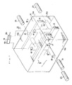
- a valve housing 10 of a control valve unit of the present invention has a predetermined lateral width, a predetermined longitudinal width and a predetermined height, and assumes a rectangular parallelepiped form.
- a first pump port passage 11 and a second pump port passage 12 which communicate with a hydraulic pump (not shown), are parallel to each other and horizontally extend in the lateral width direction of the valve housing 10 to open into an end surface 10a of the valve housing 10, which end surface 10a is perpendicular to the lateral width direction of the valve housing 10.
- a tank port passage 13 is so formed in the valve housing 10 as to be disposed in a lower portion of the valve housing 10, as to be disposed in a central position of the longitudinal width of the valve housing 10, as to horizontally extend in the lateral width direction of the valve housing 10 and as to communicate with a drain tank (not shown) to open into the end surface 10a of the valve housing 10.
- a first port passage 14 and a second port passage 15 are so formed in the valve housing 10 as not to be aligned with each other in both of the lateral width direction and the longitudinal width direction of the valve housing 10, as to extend vertically to open into an upper surface 10b of the valve housing 10 and as to communicate with a first pressure chamber 161 and a second pressure chamber 162 of a hydraulic equipment 16, respectively.
- the first port passage 14 and the second port passage 15 are so formed in the valve housing 10 as not to interfere with any of the first pump port passage 11, second pump port passage 12 and the tank port passage 13.
- a first meter-in valve receiving bore 17 and a first meter-out valve receiving bore 18 are so formed as to open into a side surface 10c of the valve housing 10 perpendicular to the longitudinal width direction of the valve housing 10, as not to be aligned with each other in the height direction and the lateral width direction of the valve housing 10, as to horizontally extend in the longitudinal width direction of the valve housing 10.
- the first meter-in valve receiving bore 17 is so disposed in the upper portion of the valve housing 10 as to penetrate the first pump port passage 11, as to communicate with the first port passage 14 and as to receive a first meter-in valve 19 therein to selectively shut off the first pump port passage 11 from the first port passage 14.
- the first meter-out valve receiving bore 18 is so disposed in the lower portion of the valve housing 10 as to open into the tank port passage 13, as to communicate with the second port passage 15 and as to receive a first meter-out valve 20 therein to selectively shut off the tank port passage 13 from the second port passage 15.
- a second meter-in valve receiving bore 21 and a second meter-out valve receiving bore 22 are so formed as to open into the other side surface 10d of the valve housing 10 perpendicular to the longitudinal width direction of the valve housing 10, as not to be aligned with each other in the height direction and the lateral width direction of the valve housing 10, as to horizontally extend in the longitudinal width direction of the valve housing 10.
- the second meter-in valve receiving bore 21 is so disposed in the upper portion of the valve housing 10 as to be aligned with the first meter-out valve receiving bore 18 in the lateral width direction of the valve housing 10, as to penetrate the second pump port passage 12, as to communicate with the second port passage 15 and as to receive a second meter-in valve 23 therein to selectively shut off the second pump port passage 12 from the second port passage 15.
- the second meter-out valve receiving bore 22 is so disposed in the lower portion of the valve housing 10 as to be aligned with the first meter-in valve receiving bore 17 in the lateral width direction of the valve housing 10, as to open into the tank port passage 13, as to communicate with the first port passage 14 and as to receive a second meter-out valve 24 therein to selectively shut off the tank port passage 13 from the first port passage 14.
- a sleeve 30 is inserted into the first meter-in valve receiving bore 17 of the first meter-in valve 19, into which sleeve 30 is inserted a poppet 31 which is pressed against a valve seat 33 under the influence of a resilient force exerted by a compression spring 32 to shut off an inlet port 34 from the interior of the sleeve 30.
- the poppet 31 is moved by means of a manually operated lever, or under the influence of a hydraulic pressure, or by means of a solenoid in a direction indicated by an arrow shown in Fig. 5 against the resilient force exerted by the compression spring 32 to separate the poppet 31 from the valve seat 33, the inlet port 34 communicates with the interior of the sleeve 30 to enable the first pump port passage 11 to communicate with the first port passage 14.
- the second meter-in valve 23 is similar in construction to the first meter-in valve 19 described above.
- a sleeve 40 is inserted into the first meter-out valve receiving bore 18 of the first meter-out valve 20, into which sleeve 40 is inserted a poppet 41 which is pressed against a valve seat 43 under the influence of a resilient force exerted by a compression spring 42 to shut off an inlet port 44 from the tank port passage 13.
- the poppet 41 is moved by means of a manually operated lever, or under the influence of a hydraulic pressure, or by means of a solenoid against the resilient force exerted by the compression spring 42 to separate the poppet 41 from the valve seat 43, the inlet port 44 communicates with the tank port passage 13.
- the second meter-out valve 24 is similar in construction to the first meter-out valve 20 described above.
- each of the first meter-in valve 19, second meter-in valve 23, first meter-out valve 20 and the second meter-out valve 24 may be a flow control valve.
Landscapes
- Engineering & Computer Science (AREA)
- General Engineering & Computer Science (AREA)
- Physics & Mathematics (AREA)
- Fluid Mechanics (AREA)
- Mechanical Engineering (AREA)
- Mining & Mineral Resources (AREA)
- Civil Engineering (AREA)
- Structural Engineering (AREA)
- Fluid-Pressure Circuits (AREA)
- Valve Housings (AREA)
- Control Of Fluid Pressure (AREA)
Claims (2)
- Eine Steuerventilanordnung mit:
einem Ventilgehäuse (10);
einem ersten und einem zweiten Pumpenmündungsdurchlaß (11, 12), welche zur Verbindung mit einer hydraulischen Pumpe in dem Ventilgehäuse (10) gebildet sind;
einem Tankmündungsdurchlaß (13), welcher zur Verbindung mit einem Auslauftank in dem Ventilgehäuse (10) gebildet ist;
einem ersten und einem zweiten Mündungslaß (14, 15), welcher zur Verbindung mit einer Hydraulikanlage (16) im Ventilgehäuse (10) gebildet sind;
einem ersten und einem zweiten Zumeßventil (19, 23), welche im Betrieb zum selektiven Absperren des Pumpenmündungsdurchlaß (11, 12) vom ersten und vom zweiten Durchlaß (14, 15) in dem Ventilgehäuse (10) eingesetzt sind;
einem ersten und einem zweiten Ablaßmeßventil (20, 24), welches im Betrieb zum selektiven Absperren des Tankmündungsdurchlaß (13) vom ersten und zweiten Mündungsdurchlaß (14, 15) im Ventilgehäuse (10) angeordnet sind, dadurch gekennzeichnet, daß das Ventilgehäuse (10) eine vorbestimmte Breite, eine vorbestimmte Länge und eine vorbestimmte Höhe aufweist und eine im wesentlichen rechteckige Parallelepipedform annimmt;
erster und zweiter Pumpenmündungsdurchlaß (11, 12) in der gleichen Höhe und parallel voneinander in Längsrichtung des Ventilgehäuses (10) voneinander beabstandet sind und sich horizontal in Breitenrichtung des Ventilgehäuses erstrecken;
der Tankmündungsdurchlaß (13) in einem tieferen Bereich des Ventilgehäuses (10) in einer mittigen Position in Längserstreckung des Ventilgehäuses angeordnet ist und sich horizontal in der Breitenrichtung des Ventilgehäuses erstreckt;
erster und zweiter Mündungsdurchlaß (14, 15) weder in Breiten- noch in Längsrichtung zueinander ausgerichtet sind und sich vertikal erstrecken, wobei sie in einer oberen Außenfläche (10b) des Ventilgehäuses münden;
das erste Zumeßventil (19) in einer ersten Zumeßventilaufnahmebohrung (17) eingesetzt ist, welche in einem oberen Bereich des Ventilgehäuses (10) gebildet ist, wobei die Aufnahmebohrung (17) in einer seitlichen Außenfläche (10c) des Ventilgehäuses senkrecht zu dessen Längsrichtung mündet und sich horizontal in dieser Längsrichtung erstreckt, wobei sie den ersten Pumpenmündungsdurchlaß (11) durchdringt und mit dem ersten Mündungsdurchlaß (14) in Verbindung steht;
das erste Ablaßmeßventil (20) in eine erste Aufnahmebohrung (18) für das Ablaßventil eingesetzt ist, welche in einem unteren Bereich des Ventilgehäuses (10) gebildet ist, wobei die Aufnahmebohrung (18) in einer seitlichen Außenseite (10c) des Ventilgehäuses senkrecht zur Längsrichtung mündet und sich horizontal in der Längsrichtung erstreckt, um aufeinanderfolgend mit dem zweiten Mündungsdurchlaß (15) und dem Tankmündungsdurchlaß (13) in Verbindung zu stehen;
das zweite Zumeßventil (23) in eine zweite Zumeßventilaufnahmebohrung (21) eingesetzt ist, welche in einem oberen Bereich des Ventilgehäuses (10) gebildet ist, wobei die Aufnahmebohrung (21) in der anderen seitlichen Außenseite (10d) des Ventilgehäuses senkrecht zur Längsrichtung mündet und sich horizontal in Längsrichtung erstreckt, wobei diese den zweiten Pumpenmündungsdurchlaß (12) durchdringt und mit dem zweiten Mündungsdurchlaß (15) in Verbindung steht;
das zweite Ablaßmeßventil (24) in einer zweiten Aufnahmebohrung (22) für das Ablaßmeßventil eingesetzt ist, welche in dem unteren Bereich des Ventilgehäuses (10) gebildet ist, wobei die Aufnahmebohrung (22) in der anderen seitlichen Außenseite (10d) des Ventilgehäuses senkrecht zur Längsrichtung mündet und sich horizontal in Längsrichtung erstreckt, wobei diese aufeinanderfolgend mit dem ersten Mündungsdurchlaß (14) und dem Tankmündungsdurchlaß (13) in Verbindung steht. - Ein Steuerventilsystem mit einer Vielzahl von Steuerventilanordnungen nach Anspruch 1 zur Steuerung einer Vielzahl von hydraulischen Anlagen (16), wobei die Vielzahl der Steuerventilanordnungen miteinander durch anliegende Stirnseiten (10a) in der Breitenrichtung des Ventilgehäuses (10) miteinander verbunden sind, wobei die entsprechenden Durchlässe (11, 12, 13) miteinander fluchten.
Applications Claiming Priority (2)
| Application Number | Priority Date | Filing Date | Title |
|---|---|---|---|
| JP63044103A JP2559612B2 (ja) | 1988-02-29 | 1988-02-29 | 操作弁装置 |
| JP44103/88 | 1988-02-29 |
Publications (3)
| Publication Number | Publication Date |
|---|---|
| EP0362401A1 EP0362401A1 (de) | 1990-04-11 |
| EP0362401A4 EP0362401A4 (en) | 1990-09-26 |
| EP0362401B1 true EP0362401B1 (de) | 1993-06-02 |
Family
ID=12682279
Family Applications (1)
| Application Number | Title | Priority Date | Filing Date |
|---|---|---|---|
| EP89902963A Expired - Lifetime EP0362401B1 (de) | 1988-02-29 | 1989-02-28 | Steuerventilanordnung |
Country Status (5)
| Country | Link |
|---|---|
| US (1) | US5046400A (de) |
| EP (1) | EP0362401B1 (de) |
| JP (1) | JP2559612B2 (de) |
| KR (1) | KR900700766A (de) |
| WO (1) | WO1989008197A1 (de) |
Families Citing this family (7)
| Publication number | Priority date | Publication date | Assignee | Title |
|---|---|---|---|---|
| DE4204229C3 (de) * | 1992-02-13 | 1997-09-04 | Katek Kabel Kommunikations Anl | Phasen-Synchronsteuereinrichtung |
| DE4408166A1 (de) * | 1994-03-11 | 1995-09-14 | Teves Gmbh Alfred | Druckregelvorrichtung |
| FR2723484B1 (fr) * | 1994-08-05 | 1996-10-31 | Endreprise Ind Sa L | Machine de preparation de faisceaux electriques comportant plusieurs postes de sertissage |
| JP3871482B2 (ja) * | 1999-12-07 | 2007-01-24 | ナブテスコ株式会社 | 航空機用流体装置 |
| JP4935301B2 (ja) * | 2006-11-01 | 2012-05-23 | コベルコ建機株式会社 | 油圧配管の圧抜き装置及び油圧配管構造 |
| EP2790072A1 (de) * | 2013-04-11 | 2014-10-15 | Siemens Aktiengesellschaft | Hydraulikanordnung mit entkoppeltem Betrieb zweier Ventileinrichtungen |
| WO2015164321A1 (en) * | 2014-04-21 | 2015-10-29 | Parker-Hannifin Corporation | Independent metering valve for mobile equipment |
Family Cites Families (26)
| Publication number | Priority date | Publication date | Assignee | Title |
|---|---|---|---|---|
| US1187960A (en) * | 1914-11-21 | 1916-06-20 | Metalwood Mfg Company | Valve. |
| US3010479A (en) * | 1956-12-28 | 1961-11-28 | Gen Electric | Time modulated fluid control valve |
| US2984257A (en) * | 1957-07-10 | 1961-05-16 | Automatic Switch Co | Pilot-operated four-way valve |
| US3556144A (en) * | 1969-11-10 | 1971-01-19 | Nordberg Manufacturing Co | Directional control valve and method of making |
| US3838710A (en) * | 1972-11-03 | 1974-10-01 | Vapor Corp | Hydraulic valve |
| US3874405A (en) * | 1973-08-24 | 1975-04-01 | Moog Inc | Multiple tow-stage electrohydraulic servovalve apparatus |
| FR2343183A1 (fr) * | 1976-03-05 | 1977-09-30 | Bouteille Daniel | Distributeur de fluide |
| JPS5419217A (en) * | 1977-07-12 | 1979-02-13 | Shinshiyuu Kikai Seisakushiyo | Multiipurpose valve unit |
| US4480527A (en) * | 1980-02-04 | 1984-11-06 | Vickers, Incorporated | Power transmission |
| US4353289A (en) * | 1980-05-29 | 1982-10-12 | Sperry Corporation | Power transmission |
| JPS5773202A (en) * | 1980-10-20 | 1982-05-07 | Toshio Masada | Direction control valve with manifold block and subplate function |
| US4479678A (en) * | 1981-07-24 | 1984-10-30 | Sharp Robert M | Pneumatic valve |
| US4611528A (en) * | 1981-11-12 | 1986-09-16 | Vickers, Incorporated | Power transmission |
| JPS6043701A (ja) * | 1983-08-22 | 1985-03-08 | Hitachi Ltd | デイジタル誤差検出器 |
| JPS61124702A (ja) * | 1984-11-22 | 1986-06-12 | Komatsu Ltd | 油圧制御装置 |
| LU85774A1 (fr) * | 1985-02-13 | 1985-07-24 | Hydrolux Sarl | Hydraulischer steuerblock |
| JPS6213803A (ja) * | 1985-07-09 | 1987-01-22 | Ishikawajima Harima Heavy Ind Co Ltd | 積層式流体切換弁 |
| IN164865B (de) * | 1985-07-12 | 1989-06-24 | Vickers Inc | |
| DE3625058A1 (de) * | 1986-07-24 | 1988-01-28 | Pleiger Maschf Paul | Ventil |
| US4747424A (en) * | 1986-10-02 | 1988-05-31 | Chapman Leonard T | Hydraulic valve |
| JPS6440702A (en) * | 1987-08-05 | 1989-02-13 | Hitachi Construction Machinery | Valve device |
| US4811650A (en) * | 1987-08-28 | 1989-03-14 | Vickers, Incorporated | Power transmission |
| JPH01133503U (de) * | 1988-03-03 | 1989-09-12 | ||
| US4984427A (en) * | 1989-09-01 | 1991-01-15 | Kabushiki Kaisha Kobe Seiko Sho | Control circuit for hydraulic actuator |
| JPH0643701U (ja) * | 1992-11-06 | 1994-06-10 | 神鋼電機株式会社 | 電空変換弁増幅器 |
| JPH06213803A (ja) * | 1993-01-21 | 1994-08-05 | Hitachi Ltd | 高感度検出方法及びその装置 |
-
1988
- 1988-02-29 JP JP63044103A patent/JP2559612B2/ja not_active Expired - Lifetime
-
1989
- 1989-02-28 WO PCT/JP1989/000204 patent/WO1989008197A1/ja not_active Ceased
- 1989-02-28 EP EP89902963A patent/EP0362401B1/de not_active Expired - Lifetime
- 1989-02-28 US US07/425,176 patent/US5046400A/en not_active Expired - Fee Related
- 1989-02-28 KR KR1019890701980A patent/KR900700766A/ko not_active Withdrawn
Also Published As
| Publication number | Publication date |
|---|---|
| JP2559612B2 (ja) | 1996-12-04 |
| JPH01220703A (ja) | 1989-09-04 |
| KR900700766A (ko) | 1990-08-16 |
| EP0362401A4 (en) | 1990-09-26 |
| US5046400A (en) | 1991-09-10 |
| EP0362401A1 (de) | 1990-04-11 |
| WO1989008197A1 (fr) | 1989-09-08 |
Similar Documents
| Publication | Publication Date | Title |
|---|---|---|
| US6505645B1 (en) | Multiple hydraulic valve assembly with a monolithic block | |
| JP3491771B2 (ja) | 圧力補償弁及び圧油供給装置 | |
| US5860445A (en) | Transfer valve manifold | |
| US5794651A (en) | Valve adaptor cap | |
| EP0747601B1 (de) | Druckölzufuhrsystem mit druckkompensierendem ventil | |
| EP0439166B1 (de) | Hydraulisches Steuerventilsystem in Blockbauweise | |
| EP0360873B1 (de) | Steuerventilanordnung mit vorsteuerung | |
| US5046400A (en) | Control valve system | |
| CN114729707A (zh) | 多重控制阀装置 | |
| EP0358778B1 (de) | Vorgesteuerte ventilanordnung | |
| GB2158552A (en) | A stacking directional-control air valve | |
| JP3514520B2 (ja) | 走行車両のバルブシステム | |
| JP3502164B2 (ja) | 多連方向切換弁装置 | |
| JP2674782B2 (ja) | 弁装置 | |
| KR20180049042A (ko) | 밸브 장치 | |
| KR100499285B1 (ko) | 토목건설기계용 유압장치의 파일럿절환밸브 | |
| JPH0434201A (ja) | 建設機械の油圧回路 | |
| JPH04136511A (ja) | 油圧回路に用いる操作弁装置 | |
| CA1290651C (en) | Multiple hydraulic control | |
| JP2899801B2 (ja) | 建設車両の油圧操作装置 | |
| JPH07238902A (ja) | 方向制御弁の圧油排出構造 | |
| JPH0513009U (ja) | 手動操作部を有するダブルパイロツト形電磁弁 | |
| JPH07139506A (ja) | 方向切換弁装置 | |
| JPH11190304A (ja) | 複合制御弁 | |
| RU97104236A (ru) | Электрогидравлическое управляющее устройство для потребителя двойного действия |
Legal Events
| Date | Code | Title | Description |
|---|---|---|---|
| PUAI | Public reference made under article 153(3) epc to a published international application that has entered the european phase |
Free format text: ORIGINAL CODE: 0009012 |
|
| 17P | Request for examination filed |
Effective date: 19891026 |
|
| AK | Designated contracting states |
Kind code of ref document: A1 Designated state(s): DE SE |
|
| A4 | Supplementary search report drawn up and despatched |
Effective date: 19900808 |
|
| AK | Designated contracting states |
Kind code of ref document: A4 Designated state(s): DE SE |
|
| 17Q | First examination report despatched |
Effective date: 19911126 |
|
| GRAA | (expected) grant |
Free format text: ORIGINAL CODE: 0009210 |
|
| AK | Designated contracting states |
Kind code of ref document: B1 Designated state(s): DE SE |
|
| REF | Corresponds to: |
Ref document number: 68906848 Country of ref document: DE Date of ref document: 19930708 |
|
| PLBE | No opposition filed within time limit |
Free format text: ORIGINAL CODE: 0009261 |
|
| 26N | No opposition filed | ||
| EAL | Se: european patent in force in sweden |
Ref document number: 89902963.1 |
|
| PGFP | Annual fee paid to national office [announced via postgrant information from national office to epo] |
Ref country code: SE Payment date: 19980218 Year of fee payment: 10 |
|
| PGFP | Annual fee paid to national office [announced via postgrant information from national office to epo] |
Ref country code: DE Payment date: 19980306 Year of fee payment: 10 |
|
| PG25 | Lapsed in a contracting state [announced via postgrant information from national office to epo] |
Ref country code: SE Free format text: LAPSE BECAUSE OF NON-PAYMENT OF DUE FEES Effective date: 19990301 |
|
| EUG | Se: european patent has lapsed |
Ref document number: 89902963.1 |
|
| PG25 | Lapsed in a contracting state [announced via postgrant information from national office to epo] |
Ref country code: DE Free format text: LAPSE BECAUSE OF NON-PAYMENT OF DUE FEES Effective date: 19991201 |
|
| EUG | Se: european patent has lapsed |
Ref document number: 89902963.1 |