EP0384361A2 - Commande de soupape pour moteur de véhicule automobile - Google Patents
Commande de soupape pour moteur de véhicule automobile Download PDFInfo
- Publication number
- EP0384361A2 EP0384361A2 EP90103166A EP90103166A EP0384361A2 EP 0384361 A2 EP0384361 A2 EP 0384361A2 EP 90103166 A EP90103166 A EP 90103166A EP 90103166 A EP90103166 A EP 90103166A EP 0384361 A2 EP0384361 A2 EP 0384361A2
- Authority
- EP
- European Patent Office
- Prior art keywords
- rocker arm
- closure
- cam
- valve
- opening
- Prior art date
- Legal status (The legal status is an assumption and is not a legal conclusion. Google has not performed a legal analysis and makes no representation as to the accuracy of the status listed.)
- Granted
Links
- 238000002485 combustion reaction Methods 0.000 claims description 21
- 230000033001 locomotion Effects 0.000 claims description 8
- 230000004044 response Effects 0.000 claims description 4
- 230000008878 coupling Effects 0.000 claims description 2
- 238000010168 coupling process Methods 0.000 claims description 2
- 238000005859 coupling reaction Methods 0.000 claims description 2
- 150000001875 compounds Chemical class 0.000 abstract description 22
- 230000007246 mechanism Effects 0.000 description 24
- 230000008901 benefit Effects 0.000 description 7
- 230000000712 assembly Effects 0.000 description 5
- 238000000429 assembly Methods 0.000 description 5
- 230000006698 induction Effects 0.000 description 5
- 230000008859 change Effects 0.000 description 4
- 238000010276 construction Methods 0.000 description 4
- 239000000314 lubricant Substances 0.000 description 4
- 239000012530 fluid Substances 0.000 description 3
- 239000000446 fuel Substances 0.000 description 3
- 230000000717 retained effect Effects 0.000 description 3
- 238000007373 indentation Methods 0.000 description 2
- 238000004519 manufacturing process Methods 0.000 description 2
- 230000009467 reduction Effects 0.000 description 2
- 238000007789 sealing Methods 0.000 description 2
- 238000006243 chemical reaction Methods 0.000 description 1
- 230000003247 decreasing effect Effects 0.000 description 1
- 230000006866 deterioration Effects 0.000 description 1
- 230000002708 enhancing effect Effects 0.000 description 1
- 230000001050 lubricating effect Effects 0.000 description 1
- 238000012423 maintenance Methods 0.000 description 1
- 230000001473 noxious effect Effects 0.000 description 1
- 230000002093 peripheral effect Effects 0.000 description 1
- 230000006798 recombination Effects 0.000 description 1
- 238000005215 recombination Methods 0.000 description 1
- 238000004904 shortening Methods 0.000 description 1
- 230000001052 transient effect Effects 0.000 description 1
- 230000007704 transition Effects 0.000 description 1
Images


Classifications
-
- F—MECHANICAL ENGINEERING; LIGHTING; HEATING; WEAPONS; BLASTING
- F01—MACHINES OR ENGINES IN GENERAL; ENGINE PLANTS IN GENERAL; STEAM ENGINES
- F01L—CYCLICALLY OPERATING VALVES FOR MACHINES OR ENGINES
- F01L1/00—Valve-gear or valve arrangements, e.g. lift-valve gear
- F01L1/30—Valve-gear or valve arrangements, e.g. lift-valve gear characterised by the provision of positively opened and closed valves, i.e. desmodromic valves
-
- F—MECHANICAL ENGINEERING; LIGHTING; HEATING; WEAPONS; BLASTING
- F01—MACHINES OR ENGINES IN GENERAL; ENGINE PLANTS IN GENERAL; STEAM ENGINES
- F01L—CYCLICALLY OPERATING VALVES FOR MACHINES OR ENGINES
- F01L1/00—Valve-gear or valve arrangements, e.g. lift-valve gear
- F01L1/12—Transmitting gear between valve drive and valve
- F01L1/18—Rocking arms or levers
-
- F—MECHANICAL ENGINEERING; LIGHTING; HEATING; WEAPONS; BLASTING
- F01—MACHINES OR ENGINES IN GENERAL; ENGINE PLANTS IN GENERAL; STEAM ENGINES
- F01L—CYCLICALLY OPERATING VALVES FOR MACHINES OR ENGINES
- F01L13/00—Modifications of valve-gear to facilitate reversing, braking, starting, changing compression ratio, or other specific operations
- F01L13/0015—Modifications of valve-gear to facilitate reversing, braking, starting, changing compression ratio, or other specific operations for optimising engine performances by modifying valve lift according to various working parameters, e.g. rotational speed, load, torque
- F01L13/0036—Modifications of valve-gear to facilitate reversing, braking, starting, changing compression ratio, or other specific operations for optimising engine performances by modifying valve lift according to various working parameters, e.g. rotational speed, load, torque the valves being driven by two or more cams with different shape, size or timing or a single cam profiled in axial and radial direction
- F01L13/0042—Modifications of valve-gear to facilitate reversing, braking, starting, changing compression ratio, or other specific operations for optimising engine performances by modifying valve lift according to various working parameters, e.g. rotational speed, load, torque the valves being driven by two or more cams with different shape, size or timing or a single cam profiled in axial and radial direction with cams being profiled in axial and radial direction
-
- Y—GENERAL TAGGING OF NEW TECHNOLOGICAL DEVELOPMENTS; GENERAL TAGGING OF CROSS-SECTIONAL TECHNOLOGIES SPANNING OVER SEVERAL SECTIONS OF THE IPC; TECHNICAL SUBJECTS COVERED BY FORMER USPC CROSS-REFERENCE ART COLLECTIONS [XRACs] AND DIGESTS
- Y10—TECHNICAL SUBJECTS COVERED BY FORMER USPC
- Y10T—TECHNICAL SUBJECTS COVERED BY FORMER US CLASSIFICATION
- Y10T74/00—Machine element or mechanism
- Y10T74/21—Elements
- Y10T74/2101—Cams
Definitions
- the present invention relates generally to an internal combustion engine valve train and more specifically to a poppet valve control arrangement which features a pair of rocker arms which are arranged in a scissor-like manner and wherein one of the arms is used to lift the valve while the other is used to close the same and wherein a cam arrangement is provided by which the valve timing can be variably adjusted in accordance with vehicular driving conditions.
- Mechanisms are known in the art of internal combustion engines for adjusting the timing of the induction and exhaust valves in a manner so as to best meet the particular conditions under which the engine is being operated. Such systems are generally adapted to be operable to provide the most efficient valve timing for slower or faster engine ranges.
- the cam for lifting the poppet valve is formed so as to have profile which changes along the longitudinal axis of the cam shaft.
- the cam face defines a compound curve and may be referred to as a compound cam.
- the cam shaft, on which the compound cam is formed is axially movable along its rotational axis so as to facilitate the adjustment of the valve timing.
- the cam shaft on which the compound cam is moved along its rotational axis the profile of the peripheral portion of the cam which comes into engagement with the cam follower changes. In this manner both the valve lift and the valve timing can be changed.
- valve it may be deemed desirable to cause the valve to be opened to a lesser degree and for a shorter period of the engine cycle during low speed/low load operation of the engine in order to provide greater fuel efficiency.
- valve opening mechanisms comprise a cam shaft on which a opening cam and a closure cam are fixedly mounted in a side by side relationship.
- a rocker shaft supports an opening rocker arm and a closure rocker arm.
- the opening rocker arm is provided with an adjust screw via which the valve clearance be be adjusted.
- a poppet valve which can be either an inlet valve or an exhaust valve, has a stem the top of which is provided with a retainer.
- the retainer is formed with a radially extending flange at the bottom thereof which is arranged to be engaged by the leading or outboard end of the closure rocker arm.
- the end of the rocker arm is formed with a U- shaped recess which defines two bifurcate finger members. These fingers extend on either side of the valve stem and engage the bottom of the retainer.
- the opening and closure cams rotate to positions wherein the high and low lift portions thereof engage the opening and and closure rocker arm followers.
- This induces the opening rocker arm to rotate in a direction which brings the end of the adjust screw into engagement with the top of the valve stem and applies a force which tends to move the valve head off the valve seat.
- the closure rocker arm is rendered rotatable in the same direction as the opening rocker arm, and thus relaxes the force which tends to bias the valve head into engagement with the valve seat.
- valve head is moved to an open position.
- the opening rocker is arranged to engage a flanged retainer at its leading end and to have a follower formed thereon at a location distal from the axis about which it is pivotally mounted.
- the closure rocker arm is pivotally mounted on the same rocker shaft as the opening one, and provided with a clearance adjust screw which is arranged to engage a portion of the opening rocker arm located proximate the shaft on which the two rocker arms are pivotally mounted.
- valve train driving mechanisms have the disadvantages that the cam clearances for both the opening and the closure rocker arms must be set very precisely and the clearance adjuster mechanisms are both complicated to build and difficult to adjust. This makes the valve train expensive to manufacture and maintain.
- the opening cam and the closure cam each have surface portions which are formed at an angle with respect to the axis of the cam shaft and thus define compound cams.
- the cam shaft is driven along its axis such that the profile of the portions of the cams which are being engaged by the cam followers is altered.
- the currently used cam profile can be selectively varied to suit the current operating conditions of the engine.
- cam followers are formed integrally on the rocker arms so as to define convex surfaces. This prevents any tendency of the cam followers to hang up or catch on any sharp corners of the cams when the cam shaft is driven along its axis, thus assuring smooth shifting of the cam shaft.
- a pair of ball and socket joints arranged along an axis running parallel to the cam shaft are provided by which the rocker arm assembly is coupled to the cylinder head.
- the rocker arm assembly is therefore prevented from pivoting laterally and attenuates sway as well as tilting thus greatly reducing engine noise and enhancing valve timing precision.
- the end of the closure rocker arm is formed with a cupped portion in which the valve stem retainer cap is reived.
- the walls of the cupped portion lend it vertical rigidity so that the bottom can be made thin. In this manner the clearance between the valve stem retainer cap and the oil seal on the valve stem sleeve can be reduced so that the valve stem can be made shorter.
- an adjustable valve train for an internal combustion engine comprises: a cam shaft which operatively connected with a crank shaft of the engine, an opening cam and a closure both being formed so as to have a cam profile which varies along the axis of the cam shaft, axial driving means for driving the cam shaft along its axis, an opening rocker arm having a valve stem engaging a portion of a valve stem of a poppet valve for exerting a force thereon in an opening direction, an opening cam follower formed on said opening rocker arm for engagement with the opening cam, a closure rocker arm having a valve stem engaging portion for engaging a valve stem of a poppet valve for exerting a force thereon in a valve closing direction, and a closure cam follower formed on the closure rocker arm for engagement with said closure cam.
- the closure and opening cam followers may have convex crowns.
- the profile of the closure cam may be such that when the valve stem is urged in the closing direction by the closure rocker arm in response to the rotation of the cam shaft, it moves at a rate that causes the valve stem to exert a force on the valve stem engaging portion of the opening rocker so as to cause the opening cam follower to pivot so as to be maintained in engagement or near engagement with a non thrust face portion of the opening cam.
- a valve train for an internal combustion engine comprises: a cam shaft driven to rotate at a rate directly proportional to the crank shaft, an opening cam, a closure cam, an opening rocker arm having a valve stem engaging portion for urging a valve stem in an opening direction, an opening cam follower formed on said opening rocker arm for engagement with said opening cam, a closure rocker arm having a valve stem engaging portion engaging a valve stem of a poppet valve for exerting a force thereon in a valve closing direction and the closure rocker arm being pivotally mounted to the opening rocker arm so as to pivot with respect thereto along a first axis, a closure cam follower formed on said closure rocker arm for engagement with the closure cam, and a pair of ball and socket pivots pivotably coupling either the opening or closing rocker arm to the cylinder head and defining a second pivoting axis about which it pivots with respect to said cylinder head.
- a closure rocker arm for an internal combustion engine comprises a valve stem closure portion having a horizontally extending web portion engaging a valve stem of a poppet valve for exerting a force thereon in a valve closing direction, and a flange portion extending at a side of the horizontally extending web portion at a substantially right angle thereto for stiffening the web portion.
- a pair of flange portions may extend at either side of the web portion so that a valve stem retainer member or a valve stem seal is accommodated therebetween.
- Another aspect of the present invention is deemed to comprise a variable valve timing arrangement for operating a valve of an internal combustion engine which features: a rotatably driven camshaft, the cam shaft being supported in the engine so as to be axially displaceable therein; servo means for selectively displacing the cam shaft along the axis thereof; first and second cams mounted on the cam shaft, the first and second cams having first and second predetermined cam configurations; a first rocker arm operatively interconnecting the valve and the cam shaft, the first rocker arm being arranged to be motivated by the first cam in a manner to open the valve; a second rocker arm operatively interconnecting the valve and the cam shaft, the second rocker arm being arranged to be motivated by the second cam in a manner to close the valve; and means associated with the first and second rocker arms for obviating movement thereof in the axial direction of the cam shaft.
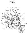
- Figs. 1 and 2 are views of a poppet valve drive train formed in accordance with the first embodiment instant invention.
- the poppet valve drive mechanism in this arrangement comprises a cam shaft 1 on which a valve opening cams 2 and closure cams 3 are formed integrally.
- the cam shaft 1 is situated in the vicinity of the upper end of the poppet valve stem 4a.
- the opening cams and closure cams 2 and 3 are engaged by cam followers 5a and 15a formed on opening rocker arm 5 and the closure rocker arm 15 of the rocker arm assembly 01.
- each poppet valve 4 two closure cams 3 and one opening cam 2 is provided.
- the opening cam 2 is situated between the closure cams 3 on the cam shaft 1.
- the poppet valve may be an exhaust valve or it may be an induction valve.
- the opening cam 2 engages a cam follower 5a formed on the opening rocker arm 5.
- the moving or "front” end of the opening rocker arm 5 constantly engages the upper end of the valve stem 4a of the poppet valve 4.
- the anchored or “rear” end of the rocker arm 5 is attached to a clearance adjuster screw 6.
- the clearance adjuster screw 6 is attached to or has formed at one end thereof, a ball 11.
- the ball 11 is received in a hemispherical indentation formed in the upper side of a socket member 7, so as to be pivotable in all directions about the central point of the spherical indentation.
- rocker arm 5 is pivotable about a ball and socket joint defined by ball 11 and the socket member 7 such that according to the rotation of the opening cam 2 the tip of the valve stem 4a a is pushed downwardly for opening the poppet valve 4.
- the closure rocker arm 15 is of a bifurcated configuration and is pivotally connected to the central portion of the opening rocker arm 5 by means of a journal pin 16. At its bifurcated upper end the closure rocker arm 15 is formed integrally with a pair of closure cam followers 15a which are in constant engagement with the closure cams 3. The closure rocker arm 15 is thus pivotable, according to the rotation of closure cams 3, with respect to the opening rocker arm 5.
- the tip of the closure rocker arm 15 engages the bottom of a valve stem retainer cap 17.
- the retainer cap member 17 is retained on the tip of the valve stem 4a by means of a collet. This engagement urges the valve stem in the upward or closing direction in accordance with the rotation of the closure cam 3 which drives the closure rocker arm 15 to pivot about the journal pin 16 by which it is attached to the opening rocker arm 5.
- the closure cam 3 is formed such that it allows the closure rocker arm 15 to move downward at the timing when the poppet valve 4 is to be opened. Conversely, at the timing when the poppet valve 4 is to be closed, the opening cam 2 is formed so as to allow the opening rocker arm to move upwardly so as to avoid interference with the closure of the poppet valve 4.
- the poppet valve drive train formed in accordance with the first embodiment does not require a valve closure spring. Instead, at the timing when the valve is to be opened, it is pushed downwardly by the opening cam 2 against an essentially non-existent resistance and thereafter the poppet valve 4 is closed by means of the closure cam 3. Therefore, the degree of resistance of the cam shaft to being moved along its axis during rotation is greatly reduced, thus allowing easy adjustment of the valve timing.
- the opening rocker arm 5 is attached to the ball 11 by means of the clearance adjuster screw 6.
- a threaded portion 6a of the clearance adjuster screw 6 is threaded into a threaded hole formed at the rear end of the opening rocker arm 5.
- Rotation of the clearance adjuster screw 6 in the inward direction drives the rear end of the opening rocker arm 5 upwards causing it to pivot about the fulcrum formed by the point of engagement between the opening cam 2 and the cam follower 5a, such that the front end of the opening rocker arm 5 is moved slightly in the opening direction.
- the clearance adjuster screw 6 turned in the opposite direction the front end of the opening rocker arm is moved to a proportional degree in the closure direction.
- the locking nut 8 is tightened so as to maintain the clearance adjustment.
- the socket member 7 is received in a blind bore 9a defined in the cylinder head 9 and formed with a passage structure which enables lubricating fluid to be constantly supplied to the interface defined between the ball 11 and the concavity.
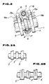
- Fig. 3A the section of the cam shaft 1 on which the compound opening cam 2 and closure cams 3 are formed in accordance with the first embodiment of the invention is shown.
- the compound cams 2 and 3 according to one embodiment are formed such that their profile changes gradually and continuously along the axis of the cam shaft 1. Therefore gradual movement of the cam shaft 1 along its axis is effective for changing the opening and closing timing and characteristics of the poppet valve 4 along a continuous curve.
- the cams 2 and 3 are therefore well suited to be operated by a system which constantly monitors the current operating conditions of the engine and adjusts the position of the cam shaft 1 in fine increments to the position exactly suited for the current mode of operation.
- the respective profiles of the opening and closure cams 2 and 3 may be such that in accordance with the position of the cam shaft 1 along its axis, the valve opening time and length of the valve stroke may be adjusted to be relatively small while the engine is running at a low speed.
- the position of the cam shaft 1 may be shifted, along its axis, to a position whereat the profiles of the respective cams 2 and 3 define a longer stroke and opening duration for the poppet valve 4.
- valve overlap can be eliminated, and the fuel efficiency is improved while the noxious emmissions of the engine can be decreased.
- the induction and exhaust efficiency can be maximized and the maximum power output of the engine can increased.
- Fig. 3B an alternative embodiment of the compound closure and opening cams is shown.
- closure cams 3′ and opening cam 2′ of the alternative embodiment differ from those of the Fig. 3A embodiment in that instead of being formed with the continuous curve which characterizes the opening and closure cams 2 and 3 of the Fig. 3A embodiment, they are stepped so as to basically provide cam surfaces defining valve timing and stroke length for two basic operation modes between which a compound intermediate section is defined.
- the intermediate section serves to guide the cam followers between the respective steps of the cams 2′ and 3′.
- the cam followers 5a and 15a of the respective rocker arms 5 and 15 are formed with radiused crowns such that, as the stepped cams are driven along the axis of the cam shaft 1 the cam followers can follow the contours of the cams 2′ and 3′ without becoming hung up on the corners between the step transitions.
- the stepped cams 2′ and 3′ are well suited for less complex control operations in which the best valve timing is more roughly approximated.
- the stepped cam configurations also have the advantage of being much easier to manufacture by conventional two axis cam grinding machinery than the cams 2 and 3 of the Fig. 3A embodiment.
- a pair of guides 19b and 19a are formed at either side of the bifurcated portion of the closure rocker arm 15.
- the guides 19a and 19b engage the outer side surfaces of the rocker arm 15 so as to prevent them from tilting or swaying from side to side. Since the closure rocker arms 15 are thus restricted, they can only pivot along horizontal axes parallel to the axis of the cam shaft, and, since the opening rocker arm 5 is pivotally mounted on the closure rocker arm 15 by way of journal pin 16, it too is restricted to pivot about axes running parallel to the cam shaft 1 and intersecting the central point of the ball 11. The tendency for the cam followers to be driven sideways by the cam surfaces when the cam shaft 1 is driven along its axis in order to adjust the valve stroke and timing is thus eliminated.
- the control mechanism depicted in Fig. 4A comprises an electro-magnetic actuator mechanism 20a for driving the cam shaft along its axis.
- the central processor unit 21 receives various signals indicative of the current driving condition of the engine such as engine speed, engine temperature engine load, accelerator position etc. and calculates therefrom a target value indicative of the appropriate cam shaft position. The central processor unit 21 then compares the target position with the current position and outputs a control signal with the appropriate cam shaft position adjustment value to the driving circuit 22.
- the driving circuit 22 is responsive to the control signal for outputting a driving pulse of a proportional value to the electro-magnetic actuator mechanism 20a.
- the electro-magnetic actuator mechanism 20a is energized to drive the cam shaft 1 along its axis in the direction and magnitude determined by the driving pulse output from the from the driver circuit 22.
- a stroke detector 23 is provided in connection with a portion of the cam shaft 1 for detecting the magnitude of change in the longitudinal position of the cam shaft 1.
- the stroke detector 23 outputs a signal indicative of the changes in longitudinal position of the cam shaft 1 to the signal convertor circuit 24.
- the signal convertor circuit 24 is operable to output an appropriate signal indicative of the magnitude of change in the cam shaft position to the position discrimination circuit 25 which adds the change data to its currently stored position data so as to arithmetically determine the current position of the cam shaft 1 and to provide a signal to the controller 21 for updating the position data in the central processor unit 21.
- the central processor unit 21 then compares the updated position data from the discrimination circuit to the current target value so as to determine whether to make further adjustments in the position of the cam shaft 1.
- the elements 21 through 25 define a control feedback loop for controlling the cam shaft positioning operations of the electromagnetic actuator 20b.
- the control mechanism according to the embodiment depicted in Fig. 4B is essentially similar to that depicted in Fig 4A with the exception that the driver signal output of the driver circuit 22 is supplied to drive a hydraulic relay valve 26, and in that the drive shaft actuator mechanism 20b is hydraulically energized by means of the hydraulic output from the hydraulic relay valve 26.
- control circuit elements 21 through 25 of the embodiment depicted in Fig. 4B are otherwise identical to those 21 through 25 depicted in Fig 4A therefore a detailed description will be omitted for the sake of brevity.
- the hydraulic relay valve 26 is connected at its input side to a hydraulic pressure source 27 which draws hydraulic fluid from a reservoir 28.
- the valve 26 is energized to open to a magnitude and/or for a duration indicated by the control signal output from the central processor unit 21 so as to hydraulically energize the hydraulic cam shaft actuator 20b to move the cam shaft 1 to the desired position.
- the control feedback loop defined by the elements 21 through 25 carry out control operations essentially identical to those described above in connection with the Fig. 4A control circuit embodiment.
- rocker arm assembly 100 opening rocker arm 50 and the closure rocker arm 150 are formed so as to be pivotably mounted independently of each other.
- closure and opening cams 2 and 3 of the second embodiment are compound type cams.
- the opening rocker arm 50 is pivotally mounted by means of a journal pin 30 and the closure rocker arm 150 is pivotally mounted by means of a journal pin 31.
- the axis defined by the journal pin 31 is parallel to the axis defined by the journal pin 30.
- the pins 30, 31 are supported at their ends in suitably bores formed in support bosses 32 formed in the cylinder head or associated structure.
- the opening and closure rocker arms according to the second embodiment are formed with cam followers 50a and 150a.
- the opening cam follower 50a is maintained in constant engagement with the opening cam 2 and the closure cam follower 150a is maintained in constant engagement with the closure cam 3.
- the opening cam 2 is operable for pushing the rear end of the rocker end upwardly so that the opening rocker arm pivots about the pin 30 so as to cause the front end of the opening rocker arm to push the end of the valve stem 4a downwards so as to open the poppet valve 4.
- closure cam 3 is operable for pushing the rear end of the rocker end upwardly so that the closure rocker arm pivots about the pin 30 so as to cause the front end of the closure rocker arm to push upwardly against the valve stem retainer cap 17 retained on the end of the valve stem 4a so as to close the poppet valve 4.
- the front end of the opening rocker arm 50a is provided with a clearance adjuster screw 50b for adjusting the valve seating clearance.
- the closure rocker arm 150 is engaged by a light closure spring 33.
- the closure spring 33 applies a light bias on the closure rocker arm 150 for urging it to rotate about the journal pin 31 in the closing direction. This light bias serves to prevent the closure rocker arm 150 from bouncing see-saw fashion between the bottom of the valve stem retainer cap and the surface of closure cam 3.
- the closure force of the closure spring 33 is small the frictional resistance it creates with respect to the shifting operation of the cam shaft 1 along its axis, is insignificant.
- journal members for the closure rocker arm 50 are shown in plan view.
- the rocker arm 50 comprises a long boss portion 50c extending from the side faces thereof.
- the boss portion 50c serves to extend the length of the bore through which the journal pin 30 is inserted so that any significant degree of lateral movement or sway of the closure rocker arm 50 is impossible.
- the boss portion 50c is dimensioned such that the ends thereof engage the stationary centering guide surfaces 32 formed at either side of the boss portion 50a so as to prevent the opening rocker arm 50 from moving along the axis of the journal pin 30.
- the opening rocker arm 50 exhibits no tendency to sway or be pushed sideways along its pivoting axis. Therefore the valve timing and or stroke can be precisely adjusted according to the position of the cam shaft. It will be noted that this precision is particularly important for the non-stepped compound cams 2 and 3 since the timing adjustments may be made in minute increments.
- rocker arm assembly 200 according to the third embodiment depicted in Figs. 7, and 8 is in most respects similar to that of the first embodiment of the invention depicted in Figs. 1 and 2. Therefore, a detailed explanation of the operation of the rocker arm assembly 200 will be omitted for the sake of brevity as it will be understood that the elements having like numerals have similar functioning characteristics to the like numbered elements in the first embodiment.
- the third embodiment of a rocker arm assembly also differs from the first embodiment in that, where the rocker arm assembly of the first embodiment is associated with a single poppet valve 4, the rocker arm assembly according to the third embodiment is associated with a pair of poppet valves 4.
- the closure and the opening rocker arms 205 and 215 comprise pairs of engaging portions 15a and 5a for engaging the valve stems 4a and the retainer cap members 17 of the pair of poppet valves 4.
- the pair of poppet valves 4 are driven in unison by the closure and opening cams 2 and 3 and the rocker arms 205 and 215 in a manner which is essentially identical to that in which the single poppet valve of the first embodiment is driven.
- FIG. 7 A third difference between the third embodiment of the rocker arm assembly and the first embodiment is most readily apparent from Fig. 7.
- the opening rocker arm 5 is adapted to be pivotally coupled to the cylinder head 9 and the closure rocker arm 15 is pivotally mounted at the mid-section of the opening rocker arm 5
- the closure rocker arm 215 is adapted to be pivotally coupled to the cylinder head 9 and the opening rocker arm 205 is pivotally mounted by means of the journal pin 16 at the mid-section of the closure rocker arm 215.
- the front ends of the rocker arms 205 and 215 are driven to move in a manner essentially identically to that of the rocker arms 5 and 15 of the first embodiment in response to the rotation of the opening and closure cams 2 and 3.
- An advantage of the arrangement wherein the opening rocker arm 205 is pivotally mounted at the mid-section of the closure rocker arm 215 is that the length of the opening rocker 205 is approximately half that of the opening rocker arm 5. This has the result of advantageously reducing the weight of the rocker arm assembly.
- the ball pivots 11 are received in a pair of hemispherical socket members 208 which are mounted in the cylinder head 9 and and arranged so as to define an axis running parallel to the axis of the cam shaft 1.
- Lubricant passages 208a are formed in connection with the hemispherical socket members 208 for supplying lubricant to the interface between the balls 11 and the hemispherical sockets 208.
- the balls 11 of the adjuster screws 6 are pivotably received in the hemispherical socket members 208 and the threaded portions of the adjuster screws 6 are received in threaded holes at the rear end of the rocker arm 215.
- Lock nuts 8 are provided for maintaining the screws 6 in position on the closure rocker arm 215.
- the closure rocker arm 215 is pivotally mounted on the cylinder head 9 by ball and socket joints defined at two points on the cylinder head 9 the rocker arm is restricted from pivoting on any other axis other than that which passes through the two ball and socket joints.
- Still another advantage obtained by providing the adjuster screws 13 on the flanges 13 projecting from the side faces of the rocker arm 215 is that the overall rocker arm assembly can be made more compact by moving the socket members relatively close to the cam shaft 1 while still allowing tool access to the lock nut 8 and adjusting screw 6.
- a fourth embodiment of a rocker arm assembly according to the invention is depicted.
- the rocker arm assembly 300 in this embodiment is essentially identical to that of the third embodiment in all respects with exception of the construction of the ball and socket joints which define the pivotal connection between the closure rocker arm 315 and the cylinder head 9, and in the spacing between the ball and socket joints.
- the balls 11 formed on the clearance adjuster screws 6 and the socket members 7 are replaced with hydraulic lash adjuster mechanisms.
- the rear end 312 of the closure rocker arm 315 is formed with a pair of spherical concavities which receive pivot balls 306 which are provided at the tops of the lash adjusters 307.
- the lash adjusters 307 are received in the blind bores 9a in the cylinder head and are constantly provided with lubricant fluid which is fed thereto under a predetermined hydraulic pressure. Accordingly, the pivot balls at the tops of the lash adjusters tend to be continuously urged upwardly with a controlled amount of force.
- the cam followers 5a, 15a are biased into engagement with their respective cams and therefore produce reactions which tend to close the scissor like arrangement and thus move the valve stem engaging portions 5b, 15b of the rocker arms 205, and 315 toward each other. This of course tends to reduce the clearances between the valve stem 4a, and valve stem retainer caps 17 and the respective rocker arms 205, and 315 to zero. Due to the compensating nature of the lash adjusters 307, it is possible to automatically maintain essentially zero clearances under all modes of engine operation even after wear has occurred on the cams 2 and 3 and cam followers 5a and 15a and engaging surfaces of the rocker arms and valve stem.
- lateral sway and or tilting of the rocker arm assembly 300 can be completely eliminated by providing a pair of ball pivots and the positions of the cam followers 15a and 5a on the compound cams can be precisely adjusted and maintained as the cam shaft 1 is driven along its axis during the valve timing and or stroke adjustment operations without the disrupting influence of lateral sway.
- the cam clearances can be constantly maintained so as to greatly reduce noise, vibration and wear of the valve train.
- the fifth embodiment of the rocker arm assembly 400 according to the invention depicted in Figs. 11 and 12 with the exception of the pivot connection between the opening rocker arm 405 and the cylinder head 9 is identical to the rocker arm assembly of the first embodiment.
- valve opening and closing operation will be ommitted as it will be understood that the valve opening and closing operations of the rocker arm assembly according to the third embodiment is essentially the same as those of the first embodiment.
- the opening rocker arm 405 is pivotally mounted on the cylinder head 9 by means means of a rocker shaft 406. As shown the rocker shaft 406 is arranged to pass through the rear end portion 405c of the opening rocker arm 405.
- the rocker shaft 406 is connected to the cylinder head 9 by means of retainer bolts 407.
- the closure rocker arm 15 as in the previous embodiments, has a bifurcated tip on which a bifurcated valve stem engaging portion 15c is formed for engaging the lower side of the valve stem cap 17 for urging the valve stem to close, and the closure cam followers 15a are formed on the parallel projecting side portions 12 at its other end for urging the rocker arm 15 into the closure position.
- the opening rocker arm 405 is disposed between the parallel side portions of the closure rocker arm 15 and supports the closure rocker arm 15 by means of the journal pin 16.
- the opening rocker arm 405 is pivotally mounted on the cylinder head 9 by means of the rocker shaft 406, lateral sway as well as tilting of the rocker arm assembly 400 out of the vertical plane is prevented.
- the valve opening and closing operations can be carried out precisely and without undue vibration.
- a further advantage of the pivoting arrangement according to the fifth embodiment is that a single rocker shaft 406 extending along the top of the cylinder head can be used to accommodate all of the rocker assemblies in the drive train. This makes construction of the valve drive train simpler and less costly.
- a sixth embodiment of a rocker arm assembly 500 is depicted.
- the rocker arm assembly 500 of the sixth embodiment is essentially the same as that of the fifth one but that whereas the rocker arm assembly 400 is associated with a single poppet valve 4, the opening rocker arm 505 and the closure rocker arm 515 each comprise a pair of valve stem engaging portions so as to engage a pair of poppet valves 4.
- FIG. 14 an alternative rocker shaft arrangement is depicted wherein the single rocker shaft 406 common to a plurality of rocker arm assemblies mentioned above, is replaced by a rocker shaft 606 which is suited to accommodating a single rocker arm assembly such as those denoted by 400 or 500 in Figs. 12 and 13.
- the mounting assembly for the rocker shaft 606 comprises a pair of adjustable end mount members 608.
- the adjustable end mount members 608 have threaded bores 608a passing through the centers thereof into which valve clearance adjuster screws 608 are threaded.
- the lower ends of the clearance adjuster screws 607a comprise non-threaded mounting stud portions 607a.
- the stud portions 607a are rotatably received in mounting sleeves 609 provided on the cylinder head 9.
- mounting bores 608b are formed on the mutually facing sides of the pair of mounting members 608 rocker shaft.
- the ends of the rocker shaft 606 are inserted into these bores so that the rocker shaft extends between the mounting members 608.
- the rocker shaft is made to pass through the boss at the rear end of the rocker arm 405 and the spacing between the mutually facing sides of the mounting members is selected to be essentially equal to the width of the rocker arm 405 so that no end play of the rocker arm 405 on the rocker shaft 606 is permitted.
- the height of the mounting members 608 relative to the cylinder head is adjustable by rotating the clearance adjuster screws 607. In this manner the cam clearance can be adjusted whereafter the lock nut 608b is retightened so as to maintain the setting.
- Figs. 15 and 16 alternative embodiments of the rocker arm assembly according to the invention are depicted in plan view.
- the seventh embodiment of the rocker arm assembly 700 shown in Fig. 15, is in all respects similar to that of the fifth embodiment (400) except for the fact that, whereas the rocker arm assembly 400 comprises a pair of side portions on which the two closure cam followers 15a are formed, the closure rocker arm 715 comprises a single arm and a single cam follower 15a.
- the rocker arm assembly 800 shown in Fig. 16 is in all respects similar to that 500 of the sixth embodiment except for the fact that again, where the rocker arm assembly 500 comprised a pair of side portions on which the two closure cam followers 15a are formed, the closure rocker 815 comprises a single arm and a single cam follower.
- a ninth embodiment of the rocker arm is invention shown.
- the ninth embodiment of the rocker arm assembly is essentially the same as the rocker arm assembly 01 of the first embodiment other than the configuration of tip portion of the closure rocker arm 915 which features a slotted bucket-like construction of the nature shown in Fig. 20.
- the end of the closure rocker arm 915 which engages the valve stem retainer cap 17 is formed with a pair of parallel side walls or flanges 20 projecting upwardly from a bottom web 18.
- a slot 18a is formed in the bottom web 18 through which the valve stem 4a is passed.
- the gap between the parallel flanges 20 is made just wide enough to accommodate the valve stem retainer cap 17 which is retained on the valve stem 4a by means of a collet 17a.
- the top face of the bottom web 18 engages the bottom of the valve stem retainer cap 17 for urging the valve 4 to close.
- the bottom web portion 18 of the tip of the closure rocker arm 915 is stiffened in the vertical directions by the parallel side flanges 20. Therefore, the bottom web portion 18 can be made relatively thin without the danger of becoming too weak or too flexible to stand up to the strain of urging the valve 4 to close at high engine speeds.
- valve stem 4a moves only vertically and lateral play or flex in the valve stem 4a is minimized.
- valve stem 4a it is also possible to reduce the overall size of the engine since the cam shaft can be moved closer to the top of the cylinder head and the valve cover (not shown) can be made smaller. What is more, since the tip of the rocker arm 915 is hollowed out and the valve stem 4a is shortened, a further advantage is realized in that the weight of the rocker arm assembly as well as the valve 4 is reduced helping the rocker arm assembly to operate smoothly and reducing the dynamic forces on the cams 2 and 3 and the cam followers 15a and 5a at high engine speeds.
- Figs. 21 and 22 the tip portion of a closure rocker arm 1015 of a tenth embodiment of a rocker arm assembly according to the invention is depicted.
- the tenth embodiment rocker arm assembly is similar to the rocker arm assembly 900 with the exception that the tip of the closure cam which engages the valve stem retainer cap 17. As will be noted, this portion is depicted in the Figs. 21 and 22 and will be discussed hereinafter.
- the closure rocker arm 1015 of the tenth embodiment varies from the closure rocker arm 915 only in that the web portion 1018 extends laterally across the top of the tip of the closure rocker arm rather than across the bottom, and the side flange portions 1020 project downwardly.
- the flange portions 1020 are spaced such that when the closure rocker arm is at the bottom of its stroke in the valve opening portion of the engine cycle, the flange portions 1020 extend at either side of the valve stem seal member 14 or in other words the flange portions 1020 define the sides of a cavity in the closure rocker arm 1015 for receiving the valve stem seal member 14 and preventing the closure rocker arm 1015 from impinging on the sealing member 14 so as to achieve the same advantageous results mentioned above in connection with shortening the valve stem and lightening the rocker arm assembly.
- Fig. 23 the end portions of a closure rocker arm 1115 according to an eleventh embodiment of the invention are depicted. As can be seen the ends of the rocker arm 1115 have exactly the same configuration as the end portion of the rocker arm 1015 the only difference being that there are two valve engaging end portions for operating two poppet valve 4 rather than one poppet valve. It will be noted that in the Fig. 23 embodiment an alignment block 1123 is provided between the end portions of the closure rocker arm 1115 for engaging the inner side portions thereof for eliminating sway in the rocker arm 1115.
- inventive elements of the instant invention are not limited to the above configurations and that various recombinations of specific elements of the embodiments described above may be performed to advantage.
Landscapes
- Engineering & Computer Science (AREA)
- Mechanical Engineering (AREA)
- General Engineering & Computer Science (AREA)
- Valve-Gear Or Valve Arrangements (AREA)
- Valve Device For Special Equipments (AREA)
Applications Claiming Priority (8)
| Application Number | Priority Date | Filing Date | Title |
|---|---|---|---|
| JP42739/89 | 1989-02-22 | ||
| JP1042739A JPH07116926B2 (ja) | 1989-02-22 | 1989-02-22 | 内燃機関の可変動弁装置 |
| JP4917689A JPH02230908A (ja) | 1989-03-01 | 1989-03-01 | 内燃機関の弁強制開閉装置 |
| JP49176/89 | 1989-03-01 | ||
| JP53263/89 | 1989-03-06 | ||
| JP5326389A JPH02233813A (ja) | 1989-03-06 | 1989-03-06 | 内燃機関の弁強制開閉装置 |
| JP57388/89 | 1989-03-09 | ||
| JP1057388A JPH02238108A (ja) | 1989-03-09 | 1989-03-09 | 内燃機関の弁強制開閉装置 |
Publications (3)
| Publication Number | Publication Date |
|---|---|
| EP0384361A2 true EP0384361A2 (fr) | 1990-08-29 |
| EP0384361A3 EP0384361A3 (fr) | 1991-04-10 |
| EP0384361B1 EP0384361B1 (fr) | 1995-09-20 |
Family
ID=27461260
Family Applications (1)
| Application Number | Title | Priority Date | Filing Date |
|---|---|---|---|
| EP90103166A Expired - Lifetime EP0384361B1 (fr) | 1989-02-22 | 1990-02-19 | Commande de soupape pour moteur de véhicule automobile |
Country Status (3)
| Country | Link |
|---|---|
| US (1) | US5048474A (fr) |
| EP (1) | EP0384361B1 (fr) |
| DE (1) | DE69022444T2 (fr) |
Cited By (9)
| Publication number | Priority date | Publication date | Assignee | Title |
|---|---|---|---|---|
| US5178105A (en) * | 1990-08-23 | 1993-01-12 | Ricardo Consulting Engineers Limited | Valve gear for internal combustion engines |
| EP0568932A1 (fr) * | 1992-05-07 | 1993-11-10 | Audi Ag | Dispositif de commande desmodromique des soupapes de moteur à combustion interne |
| EP0568931A1 (fr) * | 1992-05-07 | 1993-11-10 | Audi Ag | Dispositif de commandes desmodromique d'au moins une soupape |
| EP0843080A1 (fr) * | 1996-11-19 | 1998-05-20 | Toyota Jidosha Kabushiki Kaisha | Dispositif de commande variable pour soupapes de moteur à combustion interne |
| US6705262B2 (en) | 1998-06-16 | 2004-03-16 | Stefan Battlogg | Valve mechanism, in particular for internal combustion engines of motor vehicles |
| EP1526256A1 (fr) * | 2003-10-20 | 2005-04-27 | HONDA MOTOR CO., Ltd. | Système variable d'actionnement de soupape desmodromique |
| US6904882B2 (en) | 1999-08-12 | 2005-06-14 | Stefan Battlogg | Valve mechanism, in particular for internal combustion engines of motor vehicles |
| EP1679428A1 (fr) * | 2005-01-11 | 2006-07-12 | Fausto Pontinha Martins | Arbre à cames à profil variable pour contrôler les soupapes dans la chambre de combustion du moteur |
| ITCO20120023A1 (it) * | 2012-05-02 | 2013-11-03 | Nuovo Pignone Srl | Regolazione dei tempi di apertura di una valvola azionata da camma, compressore alternativo e metodo |
Families Citing this family (23)
| Publication number | Priority date | Publication date | Assignee | Title |
|---|---|---|---|---|
| US5211143A (en) * | 1991-05-03 | 1993-05-18 | Ford Motor Company | Adjustable valve system for an internal combustion engine |
| US5275116A (en) * | 1992-04-21 | 1994-01-04 | Merrow Machine Company, Inc. | Cam and wobble follower looper drive for sewing machine |
| US5329895A (en) * | 1992-09-30 | 1994-07-19 | Mazda Motor Corporation | System for controlling valve shift timing of an engine |
| IT1280571B1 (it) * | 1995-11-20 | 1998-01-22 | Luca Lucarini | Sistema di trasmissione del moto dalla punteria alla valvola in una distribuzione per un motore endotermico |
| ES1040073Y (es) * | 1998-04-23 | 1999-07-16 | Martinez Jose Benlloch | Dispositivo perfeccionado para el accionamiento en las valvulas de distribucion variable para motores de combustion interna. |
| JP2001065371A (ja) * | 1999-08-24 | 2001-03-13 | Toyota Motor Corp | 内燃機関の可変動弁装置 |
| CA2315595A1 (fr) * | 2000-08-08 | 2002-02-08 | Daniel G. Pomerleau | Ameliorations a des systemes de distribution a programme variable |
| US6422189B1 (en) * | 2001-01-05 | 2002-07-23 | Delphi Technologies, Inc. | Mechanical lash control apparatus for an engine cam |
| US6439178B1 (en) * | 2001-01-05 | 2002-08-27 | Delphi Technologies, Inc. | Mechanical lash adjuster apparatus for an engine cam |
| US6487997B2 (en) | 2001-04-03 | 2002-12-03 | Chris Palumbo | Springless poppet valve system |
| US7421988B2 (en) * | 2004-08-03 | 2008-09-09 | Stefan Battlogg | Positive-guidance apparatus for conversion of a rotary movement of a drive to a reciprocating movement of a part |
| DE102005053607A1 (de) * | 2005-11-10 | 2007-05-16 | Schaeffler Kg | Ventiltrieb einer Brennkraftmaschine |
| ITTO20060563A1 (it) * | 2006-07-28 | 2008-01-29 | Eaton Srl | Dispositivo di comando alzata per una valvola a stelo di motore a combustione interna o macchina operatrice |
| US7377249B1 (en) * | 2007-03-19 | 2008-05-27 | Delphi Technologies, Inc. | Outward-opening gas-exchange valve system for an internal combustion engine |
| US20090013967A1 (en) * | 2007-07-09 | 2009-01-15 | George Louie | Spring-less valve train for internal combustion engine |
| CA2679776A1 (fr) * | 2008-10-08 | 2010-04-08 | Magna Powertrain Inc. | Pompe a ailettes, a commande directe de debit |
| US8033261B1 (en) | 2008-11-03 | 2011-10-11 | Robbins Warren H | Valve actuation system and related methods |
| US9366158B1 (en) | 2010-12-22 | 2016-06-14 | James T. Dougherty | Unitary cam follower and valve preload spring for a desmodromic valve mechanism |
| US8622039B2 (en) | 2010-12-22 | 2014-01-07 | James T. Dougherty | Rockerless desmodromic valve system |
| CN102619241B (zh) * | 2012-01-12 | 2014-06-25 | 广西大学 | 一种空间可控机构式装载机 |
| KR101427958B1 (ko) * | 2012-12-18 | 2014-08-11 | 현대자동차 주식회사 | 다단 가변 밸브 리프트 장치 및 이를 포함하는 엔진 |
| DE102013111410B4 (de) * | 2013-10-16 | 2024-12-24 | Dr. Ing. H.C. F. Porsche Aktiengesellschaft | Ventiltrieb für eine Brennkraftmaschine sowie Brennkraftmaschine |
| CN118188097B (zh) * | 2024-04-25 | 2024-11-05 | 山东泰展机电科技股份有限公司 | 一种汽车用电子气门控制装置 |
Family Cites Families (23)
| Publication number | Priority date | Publication date | Assignee | Title |
|---|---|---|---|---|
| GB1051107A (fr) * | 1900-01-01 | |||
| US1633882A (en) * | 1924-11-17 | 1927-06-28 | Ballot Ernest Maurice | Valve-operating mechanism |
| US2015135A (en) * | 1934-04-24 | 1935-09-24 | George W Brady | Valve mechanism for internal combustion engines |
| US2833258A (en) * | 1955-04-28 | 1958-05-06 | Daimler Benz Ag | Valve mechanism for internal combustion engines |
| GB886151A (en) * | 1959-11-26 | 1962-01-03 | Ferdinand Anton Ernst Porsche | Improved valve gear for internal combustion engines |
| US3098472A (en) * | 1959-11-26 | 1963-07-23 | Porsche Kg | Valve control mechanism for internal combustion engine |
| US3254637A (en) * | 1962-10-03 | 1966-06-07 | Roger O Durham | Valve actuator |
| US3430614A (en) * | 1967-07-07 | 1969-03-04 | Eaton Yale & Towne | Desmodromic drive arrangement |
| US3626469A (en) * | 1968-11-12 | 1971-12-07 | Gerald J Ashley | Valve gear |
| JPS5351928A (en) * | 1976-10-22 | 1978-05-11 | Hitachi Ltd | Optical character reading method and its unit |
| US4357917A (en) * | 1978-05-15 | 1982-11-09 | Nissan Motor Company, Limited | Variable valve timing system for induction control of an internal combustion engine |
| JPS5596310A (en) * | 1979-01-12 | 1980-07-22 | Nissan Motor Co Ltd | Valve rocking device |
| JPS5838603B2 (ja) * | 1979-07-03 | 1983-08-24 | 日産自動車株式会社 | 内燃機関のバルブリフト装置 |
| JPS58202318A (ja) * | 1982-04-08 | 1983-11-25 | ジエフリ−・ロバ−ト・パ−カ− | デスモドロミツクバルブシステム |
| JPS603412A (ja) * | 1983-06-20 | 1985-01-09 | Honda Motor Co Ltd | 内燃機関の動弁機構 |
| JPS6030406A (ja) * | 1983-07-29 | 1985-02-16 | Honda Motor Co Ltd | 内燃機関のバルブ強制開閉装置 |
| JPS6032911A (ja) * | 1983-08-01 | 1985-02-20 | Honda Motor Co Ltd | 内燃機関のバルブ強制開閉装置 |
| JPS6032910A (ja) * | 1983-08-01 | 1985-02-20 | Honda Motor Co Ltd | 内燃機関のバルブ強制開閉装置 |
| FR2563274B1 (fr) * | 1984-04-18 | 1986-05-30 | Semt | Procede de changement du sens de rotation d'un moteur a combustion interne, et moteur faisant application de ce procede |
| JPS616611A (ja) * | 1984-06-20 | 1986-01-13 | Canon Inc | 焦点検出装置 |
| JPS6111408A (ja) * | 1984-06-26 | 1986-01-18 | Mitsubishi Motors Corp | エンジンの強制弁駆動装置 |
| IT1182480B (it) * | 1985-07-02 | 1987-10-05 | Fiat Auto Spa | Sistema di punteria per motori a combustione interna provvisti di alberi con camme a profilo variabile |
| US4796483A (en) * | 1987-09-11 | 1989-01-10 | The Henley Group, Inc. | Cold-formed rocker arm with cam-contacting roller |
-
1990
- 1990-02-13 US US07/479,621 patent/US5048474A/en not_active Expired - Fee Related
- 1990-02-19 EP EP90103166A patent/EP0384361B1/fr not_active Expired - Lifetime
- 1990-02-19 DE DE69022444T patent/DE69022444T2/de not_active Expired - Fee Related
Cited By (16)
| Publication number | Priority date | Publication date | Assignee | Title |
|---|---|---|---|---|
| US5178105A (en) * | 1990-08-23 | 1993-01-12 | Ricardo Consulting Engineers Limited | Valve gear for internal combustion engines |
| EP0568932A1 (fr) * | 1992-05-07 | 1993-11-10 | Audi Ag | Dispositif de commande desmodromique des soupapes de moteur à combustion interne |
| EP0568931A1 (fr) * | 1992-05-07 | 1993-11-10 | Audi Ag | Dispositif de commandes desmodromique d'au moins une soupape |
| EP0843080A1 (fr) * | 1996-11-19 | 1998-05-20 | Toyota Jidosha Kabushiki Kaisha | Dispositif de commande variable pour soupapes de moteur à combustion interne |
| US5924397A (en) * | 1996-11-19 | 1999-07-20 | Toyota Jidosha Kabushiki Kaisha | Variable valve performance apparatus for engine |
| US6705262B2 (en) | 1998-06-16 | 2004-03-16 | Stefan Battlogg | Valve mechanism, in particular for internal combustion engines of motor vehicles |
| US6796277B2 (en) | 1998-06-16 | 2004-09-28 | Stefan Battlogg | Valve mechanism, in particular for internal combustion engines of motor vehicles |
| US6904882B2 (en) | 1999-08-12 | 2005-06-14 | Stefan Battlogg | Valve mechanism, in particular for internal combustion engines of motor vehicles |
| EP1526256A1 (fr) * | 2003-10-20 | 2005-04-27 | HONDA MOTOR CO., Ltd. | Système variable d'actionnement de soupape desmodromique |
| US6953012B2 (en) | 2003-10-20 | 2005-10-11 | Honda Motor Co., Ltd. | Forced opening and closing type valve operating system |
| EP1679428A1 (fr) * | 2005-01-11 | 2006-07-12 | Fausto Pontinha Martins | Arbre à cames à profil variable pour contrôler les soupapes dans la chambre de combustion du moteur |
| ITCO20120023A1 (it) * | 2012-05-02 | 2013-11-03 | Nuovo Pignone Srl | Regolazione dei tempi di apertura di una valvola azionata da camma, compressore alternativo e metodo |
| WO2013164370A1 (fr) * | 2012-05-02 | 2013-11-07 | Nuovo Pignone Srl | Réglage des temps d'ouverture d'une soupape actionnée par came, compresseur alternatif et procédé |
| CN104395605A (zh) * | 2012-05-02 | 2015-03-04 | 诺沃皮尼奥内股份有限公司 | 调节凸轮促动阀的开放时间、往复式压缩机和方法 |
| RU2619513C2 (ru) * | 2012-05-02 | 2017-05-16 | Нуово Пиньоне СРЛ | Регулирование времени открытия клапана с кулачковым приводом, поршневой компрессор и способ |
| US10253760B2 (en) | 2012-05-02 | 2019-04-09 | Nuovo Pignone Srl | Adjusting opening times of a cam actuated valve, reciprocating compressor and method |
Also Published As
| Publication number | Publication date |
|---|---|
| US5048474A (en) | 1991-09-17 |
| EP0384361B1 (fr) | 1995-09-20 |
| DE69022444T2 (de) | 1996-02-08 |
| DE69022444D1 (de) | 1995-10-26 |
| EP0384361A3 (fr) | 1991-04-10 |
Similar Documents
| Publication | Publication Date | Title |
|---|---|---|
| US5048474A (en) | Valve train for automotive engine | |
| US4811698A (en) | Valve timing adjusting mechanism for internal combustion engine for adjusting timing of intake valve and/or exhaust valve corresponding to engine operating conditions | |
| US5494009A (en) | Valve control device for internal combustion engine | |
| EP0275714B1 (fr) | Mécanisme de commande de soupapes pour un moteur à combustion interne | |
| US7469669B2 (en) | Variable valve train mechanism of internal combustion engine | |
| US4567861A (en) | Engine valve operating system for internal combustion engine | |
| EP0416628A1 (fr) | Disposition de culbuteurs pour système de commande de soupapes variable | |
| US6382149B1 (en) | Valve timing system for an internal combustion engine | |
| US4825822A (en) | Rocker arm arrangement for multi-valve internal combustion engine | |
| GB2237326A (en) | I.c.engine rocker valve gear | |
| US4944256A (en) | Rocker arm arrangement for internal combustion engine poppet valves and the like | |
| US7069890B2 (en) | Valve train device for an engine | |
| CA2280266A1 (fr) | Mecanisme de reglage de soupapes | |
| US20050126526A1 (en) | Valve train device for an engine | |
| JP3268847B2 (ja) | エンジンのバルブ駆動装置 | |
| US4495902A (en) | Mechanism for variably controlling an internal combustion engine valve | |
| KR100897263B1 (ko) | 무단 가변 밸브 리프트 장치 | |
| JPH02221612A (ja) | 内燃機関の可変動弁装置 | |
| JPH0321727B2 (fr) | ||
| US20030159667A1 (en) | Adjustment mechanism for valves | |
| JPH0252086B2 (fr) | ||
| JPH0133773Y2 (fr) | ||
| JPH03156112A (ja) | エンジンの可変動弁装置 | |
| KR0178821B1 (ko) | 엔진의 가변동 밸브 장치 | |
| JPH0523764Y2 (fr) |
Legal Events
| Date | Code | Title | Description |
|---|---|---|---|
| PUAI | Public reference made under article 153(3) epc to a published international application that has entered the european phase |
Free format text: ORIGINAL CODE: 0009012 |
|
| 17P | Request for examination filed |
Effective date: 19900219 |
|
| AK | Designated contracting states |
Kind code of ref document: A2 Designated state(s): DE GB |
|
| PUAL | Search report despatched |
Free format text: ORIGINAL CODE: 0009013 |
|
| AK | Designated contracting states |
Kind code of ref document: A3 Designated state(s): DE GB |
|
| 17Q | First examination report despatched |
Effective date: 19921001 |
|
| GRAA | (expected) grant |
Free format text: ORIGINAL CODE: 0009210 |
|
| AK | Designated contracting states |
Kind code of ref document: B1 Designated state(s): DE GB |
|
| REF | Corresponds to: |
Ref document number: 69022444 Country of ref document: DE Date of ref document: 19951026 |
|
| PLBE | No opposition filed within time limit |
Free format text: ORIGINAL CODE: 0009261 |
|
| STAA | Information on the status of an ep patent application or granted ep patent |
Free format text: STATUS: NO OPPOSITION FILED WITHIN TIME LIMIT |
|
| 26N | No opposition filed | ||
| PGFP | Annual fee paid to national office [announced via postgrant information from national office to epo] |
Ref country code: GB Payment date: 19990218 Year of fee payment: 10 |
|
| PGFP | Annual fee paid to national office [announced via postgrant information from national office to epo] |
Ref country code: DE Payment date: 19990301 Year of fee payment: 10 |
|
| PG25 | Lapsed in a contracting state [announced via postgrant information from national office to epo] |
Ref country code: GB Free format text: LAPSE BECAUSE OF NON-PAYMENT OF DUE FEES Effective date: 20000219 |
|
| GBPC | Gb: european patent ceased through non-payment of renewal fee |
Effective date: 20000219 |
|
| PG25 | Lapsed in a contracting state [announced via postgrant information from national office to epo] |
Ref country code: DE Free format text: LAPSE BECAUSE OF NON-PAYMENT OF DUE FEES Effective date: 20001201 |