EP0421183B1 - Steuerungssystem für ein stufenloses Getriebe - Google Patents
Steuerungssystem für ein stufenloses Getriebe Download PDFInfo
- Publication number
- EP0421183B1 EP0421183B1 EP90117918A EP90117918A EP0421183B1 EP 0421183 B1 EP0421183 B1 EP 0421183B1 EP 90117918 A EP90117918 A EP 90117918A EP 90117918 A EP90117918 A EP 90117918A EP 0421183 B1 EP0421183 B1 EP 0421183B1
- Authority
- EP
- European Patent Office
- Prior art keywords
- pressure
- clutch
- engine torque
- line pressure
- variable transmission
- Prior art date
- Legal status (The legal status is an assumption and is not a legal conclusion. Google has not performed a legal analysis and makes no representation as to the accuracy of the status listed.)
- Expired - Lifetime
Links
- 230000005540 biological transmission Effects 0.000 title claims description 29
- 238000001514 detection method Methods 0.000 claims description 13
- 230000003247 decreasing effect Effects 0.000 claims description 4
- 239000003921 oil Substances 0.000 description 26
- 230000006870 function Effects 0.000 description 6
- 239000010720 hydraulic oil Substances 0.000 description 6
- 238000010586 diagram Methods 0.000 description 5
- 230000001133 acceleration Effects 0.000 description 3
- 230000001174 ascending effect Effects 0.000 description 3
- 238000002485 combustion reaction Methods 0.000 description 3
- 238000010276 construction Methods 0.000 description 3
- 238000000034 method Methods 0.000 description 3
- 230000002093 peripheral effect Effects 0.000 description 3
- 230000000994 depressogenic effect Effects 0.000 description 1
- 230000006866 deterioration Effects 0.000 description 1
- 238000006073 displacement reaction Methods 0.000 description 1
- 230000000694 effects Effects 0.000 description 1
- 239000000446 fuel Substances 0.000 description 1
- 238000002347 injection Methods 0.000 description 1
- 239000007924 injection Substances 0.000 description 1
- 238000004519 manufacturing process Methods 0.000 description 1
- QSHDDOUJBYECFT-UHFFFAOYSA-N mercury Chemical compound [Hg] QSHDDOUJBYECFT-UHFFFAOYSA-N 0.000 description 1
- 229910052753 mercury Inorganic materials 0.000 description 1
Images


Classifications
-
- F—MECHANICAL ENGINEERING; LIGHTING; HEATING; WEAPONS; BLASTING
- F16—ENGINEERING ELEMENTS AND UNITS; GENERAL MEASURES FOR PRODUCING AND MAINTAINING EFFECTIVE FUNCTIONING OF MACHINES OR INSTALLATIONS; THERMAL INSULATION IN GENERAL
- F16H—GEARING
- F16H61/00—Control functions within control units of change-speed- or reversing-gearings for conveying rotary motion ; Control of exclusively fluid gearing, friction gearing, gearings with endless flexible members or other particular types of gearing
- F16H61/66—Control functions within control units of change-speed- or reversing-gearings for conveying rotary motion ; Control of exclusively fluid gearing, friction gearing, gearings with endless flexible members or other particular types of gearing specially adapted for continuously variable gearings
- F16H61/662—Control functions within control units of change-speed- or reversing-gearings for conveying rotary motion ; Control of exclusively fluid gearing, friction gearing, gearings with endless flexible members or other particular types of gearing specially adapted for continuously variable gearings with endless flexible members
- F16H61/66254—Control functions within control units of change-speed- or reversing-gearings for conveying rotary motion ; Control of exclusively fluid gearing, friction gearing, gearings with endless flexible members or other particular types of gearing specially adapted for continuously variable gearings with endless flexible members controlling of shifting being influenced by a signal derived from the engine and the main coupling
- F16H61/66259—Control functions within control units of change-speed- or reversing-gearings for conveying rotary motion ; Control of exclusively fluid gearing, friction gearing, gearings with endless flexible members or other particular types of gearing specially adapted for continuously variable gearings with endless flexible members controlling of shifting being influenced by a signal derived from the engine and the main coupling using electrical or electronical sensing or control means
-
- B—PERFORMING OPERATIONS; TRANSPORTING
- B60—VEHICLES IN GENERAL
- B60W—CONJOINT CONTROL OF VEHICLE SUB-UNITS OF DIFFERENT TYPE OR DIFFERENT FUNCTION; CONTROL SYSTEMS SPECIALLY ADAPTED FOR HYBRID VEHICLES; ROAD VEHICLE DRIVE CONTROL SYSTEMS FOR PURPOSES NOT RELATED TO THE CONTROL OF A PARTICULAR SUB-UNIT
- B60W10/00—Conjoint control of vehicle sub-units of different type or different function
- B60W10/02—Conjoint control of vehicle sub-units of different type or different function including control of driveline clutches
-
- B—PERFORMING OPERATIONS; TRANSPORTING
- B60—VEHICLES IN GENERAL
- B60W—CONJOINT CONTROL OF VEHICLE SUB-UNITS OF DIFFERENT TYPE OR DIFFERENT FUNCTION; CONTROL SYSTEMS SPECIALLY ADAPTED FOR HYBRID VEHICLES; ROAD VEHICLE DRIVE CONTROL SYSTEMS FOR PURPOSES NOT RELATED TO THE CONTROL OF A PARTICULAR SUB-UNIT
- B60W10/00—Conjoint control of vehicle sub-units of different type or different function
- B60W10/10—Conjoint control of vehicle sub-units of different type or different function including control of change-speed gearings
-
- B—PERFORMING OPERATIONS; TRANSPORTING
- B60—VEHICLES IN GENERAL
- B60W—CONJOINT CONTROL OF VEHICLE SUB-UNITS OF DIFFERENT TYPE OR DIFFERENT FUNCTION; CONTROL SYSTEMS SPECIALLY ADAPTED FOR HYBRID VEHICLES; ROAD VEHICLE DRIVE CONTROL SYSTEMS FOR PURPOSES NOT RELATED TO THE CONTROL OF A PARTICULAR SUB-UNIT
- B60W10/00—Conjoint control of vehicle sub-units of different type or different function
- B60W10/10—Conjoint control of vehicle sub-units of different type or different function including control of change-speed gearings
- B60W10/101—Infinitely variable gearings
- B60W10/107—Infinitely variable gearings with endless flexible members
-
- B—PERFORMING OPERATIONS; TRANSPORTING
- B60—VEHICLES IN GENERAL
- B60W—CONJOINT CONTROL OF VEHICLE SUB-UNITS OF DIFFERENT TYPE OR DIFFERENT FUNCTION; CONTROL SYSTEMS SPECIALLY ADAPTED FOR HYBRID VEHICLES; ROAD VEHICLE DRIVE CONTROL SYSTEMS FOR PURPOSES NOT RELATED TO THE CONTROL OF A PARTICULAR SUB-UNIT
- B60W30/00—Purposes of road vehicle drive control systems not related to the control of a particular sub-unit, e.g. of systems using conjoint control of vehicle sub-units
- B60W30/18—Propelling the vehicle
-
- B—PERFORMING OPERATIONS; TRANSPORTING
- B60—VEHICLES IN GENERAL
- B60W—CONJOINT CONTROL OF VEHICLE SUB-UNITS OF DIFFERENT TYPE OR DIFFERENT FUNCTION; CONTROL SYSTEMS SPECIALLY ADAPTED FOR HYBRID VEHICLES; ROAD VEHICLE DRIVE CONTROL SYSTEMS FOR PURPOSES NOT RELATED TO THE CONTROL OF A PARTICULAR SUB-UNIT
- B60W30/00—Purposes of road vehicle drive control systems not related to the control of a particular sub-unit, e.g. of systems using conjoint control of vehicle sub-units
- B60W30/18—Propelling the vehicle
- B60W30/1819—Propulsion control with control means using analogue circuits, relays or mechanical links
-
- F—MECHANICAL ENGINEERING; LIGHTING; HEATING; WEAPONS; BLASTING
- F16—ENGINEERING ELEMENTS AND UNITS; GENERAL MEASURES FOR PRODUCING AND MAINTAINING EFFECTIVE FUNCTIONING OF MACHINES OR INSTALLATIONS; THERMAL INSULATION IN GENERAL
- F16D—COUPLINGS FOR TRANSMITTING ROTATION; CLUTCHES; BRAKES
- F16D48/00—External control of clutches
- F16D48/06—Control by electric or electronic means, e.g. of fluid pressure
- F16D48/066—Control of fluid pressure, e.g. using an accumulator
-
- B—PERFORMING OPERATIONS; TRANSPORTING
- B60—VEHICLES IN GENERAL
- B60W—CONJOINT CONTROL OF VEHICLE SUB-UNITS OF DIFFERENT TYPE OR DIFFERENT FUNCTION; CONTROL SYSTEMS SPECIALLY ADAPTED FOR HYBRID VEHICLES; ROAD VEHICLE DRIVE CONTROL SYSTEMS FOR PURPOSES NOT RELATED TO THE CONTROL OF A PARTICULAR SUB-UNIT
- B60W2555/00—Input parameters relating to exterior conditions, not covered by groups B60W2552/00, B60W2554/00
- B60W2555/40—Altitude
-
- F—MECHANICAL ENGINEERING; LIGHTING; HEATING; WEAPONS; BLASTING
- F16—ENGINEERING ELEMENTS AND UNITS; GENERAL MEASURES FOR PRODUCING AND MAINTAINING EFFECTIVE FUNCTIONING OF MACHINES OR INSTALLATIONS; THERMAL INSULATION IN GENERAL
- F16D—COUPLINGS FOR TRANSMITTING ROTATION; CLUTCHES; BRAKES
- F16D2500/00—External control of clutches by electric or electronic means
- F16D2500/10—System to be controlled
- F16D2500/102—Actuator
- F16D2500/1026—Hydraulic
-
- F—MECHANICAL ENGINEERING; LIGHTING; HEATING; WEAPONS; BLASTING
- F16—ENGINEERING ELEMENTS AND UNITS; GENERAL MEASURES FOR PRODUCING AND MAINTAINING EFFECTIVE FUNCTIONING OF MACHINES OR INSTALLATIONS; THERMAL INSULATION IN GENERAL
- F16D—COUPLINGS FOR TRANSMITTING ROTATION; CLUTCHES; BRAKES
- F16D2500/00—External control of clutches by electric or electronic means
- F16D2500/10—System to be controlled
- F16D2500/108—Gear
- F16D2500/1088—CVT
-
- F—MECHANICAL ENGINEERING; LIGHTING; HEATING; WEAPONS; BLASTING
- F16—ENGINEERING ELEMENTS AND UNITS; GENERAL MEASURES FOR PRODUCING AND MAINTAINING EFFECTIVE FUNCTIONING OF MACHINES OR INSTALLATIONS; THERMAL INSULATION IN GENERAL
- F16D—COUPLINGS FOR TRANSMITTING ROTATION; CLUTCHES; BRAKES
- F16D2500/00—External control of clutches by electric or electronic means
- F16D2500/30—Signal inputs
- F16D2500/302—Signal inputs from the actuator
- F16D2500/3021—Angle
-
- F—MECHANICAL ENGINEERING; LIGHTING; HEATING; WEAPONS; BLASTING
- F16—ENGINEERING ELEMENTS AND UNITS; GENERAL MEASURES FOR PRODUCING AND MAINTAINING EFFECTIVE FUNCTIONING OF MACHINES OR INSTALLATIONS; THERMAL INSULATION IN GENERAL
- F16D—COUPLINGS FOR TRANSMITTING ROTATION; CLUTCHES; BRAKES
- F16D2500/00—External control of clutches by electric or electronic means
- F16D2500/30—Signal inputs
- F16D2500/302—Signal inputs from the actuator
- F16D2500/3026—Stroke
-
- F—MECHANICAL ENGINEERING; LIGHTING; HEATING; WEAPONS; BLASTING
- F16—ENGINEERING ELEMENTS AND UNITS; GENERAL MEASURES FOR PRODUCING AND MAINTAINING EFFECTIVE FUNCTIONING OF MACHINES OR INSTALLATIONS; THERMAL INSULATION IN GENERAL
- F16D—COUPLINGS FOR TRANSMITTING ROTATION; CLUTCHES; BRAKES
- F16D2500/00—External control of clutches by electric or electronic means
- F16D2500/30—Signal inputs
- F16D2500/306—Signal inputs from the engine
- F16D2500/3065—Torque of the engine
-
- F—MECHANICAL ENGINEERING; LIGHTING; HEATING; WEAPONS; BLASTING
- F16—ENGINEERING ELEMENTS AND UNITS; GENERAL MEASURES FOR PRODUCING AND MAINTAINING EFFECTIVE FUNCTIONING OF MACHINES OR INSTALLATIONS; THERMAL INSULATION IN GENERAL
- F16D—COUPLINGS FOR TRANSMITTING ROTATION; CLUTCHES; BRAKES
- F16D2500/00—External control of clutches by electric or electronic means
- F16D2500/30—Signal inputs
- F16D2500/306—Signal inputs from the engine
- F16D2500/3067—Speed of the engine
-
- F—MECHANICAL ENGINEERING; LIGHTING; HEATING; WEAPONS; BLASTING
- F16—ENGINEERING ELEMENTS AND UNITS; GENERAL MEASURES FOR PRODUCING AND MAINTAINING EFFECTIVE FUNCTIONING OF MACHINES OR INSTALLATIONS; THERMAL INSULATION IN GENERAL
- F16D—COUPLINGS FOR TRANSMITTING ROTATION; CLUTCHES; BRAKES
- F16D2500/00—External control of clutches by electric or electronic means
- F16D2500/30—Signal inputs
- F16D2500/308—Signal inputs from the transmission
- F16D2500/30806—Engaged transmission ratio
-
- F—MECHANICAL ENGINEERING; LIGHTING; HEATING; WEAPONS; BLASTING
- F16—ENGINEERING ELEMENTS AND UNITS; GENERAL MEASURES FOR PRODUCING AND MAINTAINING EFFECTIVE FUNCTIONING OF MACHINES OR INSTALLATIONS; THERMAL INSULATION IN GENERAL
- F16D—COUPLINGS FOR TRANSMITTING ROTATION; CLUTCHES; BRAKES
- F16D2500/00—External control of clutches by electric or electronic means
- F16D2500/30—Signal inputs
- F16D2500/31—Signal inputs from the vehicle
- F16D2500/3101—Detection of a brake actuation by a sensor on the brake
-
- F—MECHANICAL ENGINEERING; LIGHTING; HEATING; WEAPONS; BLASTING
- F16—ENGINEERING ELEMENTS AND UNITS; GENERAL MEASURES FOR PRODUCING AND MAINTAINING EFFECTIVE FUNCTIONING OF MACHINES OR INSTALLATIONS; THERMAL INSULATION IN GENERAL
- F16D—COUPLINGS FOR TRANSMITTING ROTATION; CLUTCHES; BRAKES
- F16D2500/00—External control of clutches by electric or electronic means
- F16D2500/30—Signal inputs
- F16D2500/31—Signal inputs from the vehicle
- F16D2500/3108—Vehicle speed
-
- F—MECHANICAL ENGINEERING; LIGHTING; HEATING; WEAPONS; BLASTING
- F16—ENGINEERING ELEMENTS AND UNITS; GENERAL MEASURES FOR PRODUCING AND MAINTAINING EFFECTIVE FUNCTIONING OF MACHINES OR INSTALLATIONS; THERMAL INSULATION IN GENERAL
- F16D—COUPLINGS FOR TRANSMITTING ROTATION; CLUTCHES; BRAKES
- F16D2500/00—External control of clutches by electric or electronic means
- F16D2500/30—Signal inputs
- F16D2500/312—External to the vehicle
- F16D2500/3121—Ambient conditions, e.g. air humidity, air temperature, ambient pressure
-
- F—MECHANICAL ENGINEERING; LIGHTING; HEATING; WEAPONS; BLASTING
- F16—ENGINEERING ELEMENTS AND UNITS; GENERAL MEASURES FOR PRODUCING AND MAINTAINING EFFECTIVE FUNCTIONING OF MACHINES OR INSTALLATIONS; THERMAL INSULATION IN GENERAL
- F16D—COUPLINGS FOR TRANSMITTING ROTATION; CLUTCHES; BRAKES
- F16D2500/00—External control of clutches by electric or electronic means
- F16D2500/30—Signal inputs
- F16D2500/314—Signal inputs from the user
- F16D2500/31406—Signal inputs from the user input from pedals
- F16D2500/3144—Accelerator pedal position
-
- F—MECHANICAL ENGINEERING; LIGHTING; HEATING; WEAPONS; BLASTING
- F16—ENGINEERING ELEMENTS AND UNITS; GENERAL MEASURES FOR PRODUCING AND MAINTAINING EFFECTIVE FUNCTIONING OF MACHINES OR INSTALLATIONS; THERMAL INSULATION IN GENERAL
- F16D—COUPLINGS FOR TRANSMITTING ROTATION; CLUTCHES; BRAKES
- F16D2500/00—External control of clutches by electric or electronic means
- F16D2500/30—Signal inputs
- F16D2500/314—Signal inputs from the user
- F16D2500/3146—Signal inputs from the user input from levers
- F16D2500/31466—Gear lever
-
- F—MECHANICAL ENGINEERING; LIGHTING; HEATING; WEAPONS; BLASTING
- F16—ENGINEERING ELEMENTS AND UNITS; GENERAL MEASURES FOR PRODUCING AND MAINTAINING EFFECTIVE FUNCTIONING OF MACHINES OR INSTALLATIONS; THERMAL INSULATION IN GENERAL
- F16D—COUPLINGS FOR TRANSMITTING ROTATION; CLUTCHES; BRAKES
- F16D2500/00—External control of clutches by electric or electronic means
- F16D2500/50—Problem to be solved by the control system
- F16D2500/508—Relating driving conditions
- F16D2500/50858—Selecting a Mode of operation
-
- F—MECHANICAL ENGINEERING; LIGHTING; HEATING; WEAPONS; BLASTING
- F16—ENGINEERING ELEMENTS AND UNITS; GENERAL MEASURES FOR PRODUCING AND MAINTAINING EFFECTIVE FUNCTIONING OF MACHINES OR INSTALLATIONS; THERMAL INSULATION IN GENERAL
- F16D—COUPLINGS FOR TRANSMITTING ROTATION; CLUTCHES; BRAKES
- F16D2500/00—External control of clutches by electric or electronic means
- F16D2500/70—Details about the implementation of the control system
- F16D2500/702—Look-up tables
- F16D2500/70252—Clutch torque
- F16D2500/70258—Throttle
-
- F—MECHANICAL ENGINEERING; LIGHTING; HEATING; WEAPONS; BLASTING
- F16—ENGINEERING ELEMENTS AND UNITS; GENERAL MEASURES FOR PRODUCING AND MAINTAINING EFFECTIVE FUNCTIONING OF MACHINES OR INSTALLATIONS; THERMAL INSULATION IN GENERAL
- F16D—COUPLINGS FOR TRANSMITTING ROTATION; CLUTCHES; BRAKES
- F16D2500/00—External control of clutches by electric or electronic means
- F16D2500/70—Details about the implementation of the control system
- F16D2500/704—Output parameters from the control unit; Target parameters to be controlled
- F16D2500/70402—Actuator parameters
- F16D2500/70406—Pressure
-
- F—MECHANICAL ENGINEERING; LIGHTING; HEATING; WEAPONS; BLASTING
- F16—ENGINEERING ELEMENTS AND UNITS; GENERAL MEASURES FOR PRODUCING AND MAINTAINING EFFECTIVE FUNCTIONING OF MACHINES OR INSTALLATIONS; THERMAL INSULATION IN GENERAL
- F16D—COUPLINGS FOR TRANSMITTING ROTATION; CLUTCHES; BRAKES
- F16D2500/00—External control of clutches by electric or electronic means
- F16D2500/70—Details about the implementation of the control system
- F16D2500/706—Strategy of control
- F16D2500/70668—Signal filtering
-
- F—MECHANICAL ENGINEERING; LIGHTING; HEATING; WEAPONS; BLASTING
- F16—ENGINEERING ELEMENTS AND UNITS; GENERAL MEASURES FOR PRODUCING AND MAINTAINING EFFECTIVE FUNCTIONING OF MACHINES OR INSTALLATIONS; THERMAL INSULATION IN GENERAL
- F16H—GEARING
- F16H59/00—Control inputs to control units of change-speed- or reversing-gearings for conveying rotary motion
- F16H59/60—Inputs being a function of ambient conditions
- F16H59/62—Atmospheric pressure
-
- F—MECHANICAL ENGINEERING; LIGHTING; HEATING; WEAPONS; BLASTING
- F16—ENGINEERING ELEMENTS AND UNITS; GENERAL MEASURES FOR PRODUCING AND MAINTAINING EFFECTIVE FUNCTIONING OF MACHINES OR INSTALLATIONS; THERMAL INSULATION IN GENERAL
- F16H—GEARING
- F16H63/00—Control outputs from the control unit to change-speed- or reversing-gearings for conveying rotary motion or to other devices than the final output mechanism
- F16H63/40—Control outputs from the control unit to change-speed- or reversing-gearings for conveying rotary motion or to other devices than the final output mechanism comprising signals other than signals for actuating the final output mechanisms
- F16H63/46—Signals to a clutch outside the gearbox
Definitions
- the invention relates to a continuous speed variable control apparatus according to the preamble of claim 1.
- Such a transmission control apparatus is known from US-A-4,642,068, wherein the line pressure is adjusted in relation to engine torque which is calculated on the basis of engine speed, an intake throttle position and atmospheric pressure.
- the line pressure is alternatively adjusted in relation to the atmospheric pressure which is detected from the feed back correction of fuel injection. A correction is effected only if the selected range of the transmission is D.
- a transmission system is disposed between the internal combustion engine and driving wheels.
- This transmission system changes the driving force of the driving wheels and traveling speed in accordance with traveling conditions of the vehicle which change in a wide range, thereby to derive the full performance of the internal combustion engine.
- a continuous speed variable transmission control apparatus for transmitting power by increasing or decreasing the turning radius of a belt looped around pulleys, which pulleys each include a pulley element fixed to a rotational shaft and a movable pulley element which is separably supported relative to the stationary pulley element.
- the engine torque is calculated from the opening degree of the throttle when the vehicle is started, and a clutch target pressure is obtained as a feed forward quantity.
- Figures 1 through 6 show an embodiment of the present invention.
- the numeral 2 denotes a belt drive type continuous speed variable transmission, 2A a belt, 4 a drive side pulley having an axially stationary drive side pulley element 6 and an axially movable drive side pulley element 8, 10 a driven side pulley having an axially stationary driven side pulley element 12 and an axially movable driven side pulley element 14.
- the pulley element 6 is fixed to a rotational shaft 16, and the movable pulley element 8 is supported relative to the rotational shaft 16 such that the pulley element 8 can move in the axial direction of the rotational shaft 16 but cannot rotate therewith.
- the driven side pulley 10, including stationary pulley element 12 and movably pulley element 14, has a similar construction.
- the drive side movable pulley element 8 and the driven side movable pulley element 14 are provided with first and second housings 18 and 20, respectively, and first and second hydraulic oil chambers 22 and 24 are defined by the first and second housings 18 and 20, respectively.
- Biasing means 26 such as a spring is disposed within the second hydraulic oil chamber 24 for urging movable pulley element 14 so as to expand the second hydraulic oil chamber 24.
- the rotational shaft 16 is provided with an oil pump 28, which communicates with the first and second hydraulic oil chambers 22 and 24 through first and second oil passages 30 and 32, respectively.
- the first oil passage 30 is provided at its intermediate part with a primary pressure control valve 34 acting as a change speed control valve for controlling primary pressure as input shaft sheave pressure.
- a constant pressure control valve 38 is provided between the oil pump 28 and the primary pressure control valve 34, and communicates with the first oil passage 30 through a third oil passage 36.
- the valve 38 is adapted to control line pressure (generally 5 to 25 kg/cm2) to a constant pressure (3 to 4 kg/cm2).
- the primary pressure control valve 34 communicates with a primary pressure controlling first three-way electromagnetic valve 42 through a fourth oil passage 40.
- an intermediate part of the second oil passage 32 communicates through a fifth oil passage 46, with a line pressure control valve 44 having an escape valve function for controlling line pressure as pump pressure, and this line pressure control valve 44 communicates with a line pressure controlling second threeway electromagnetic valve 50 through a sixth oil passage 48.
- an intermediate part of the second oil passage 32 between the second hydraulic oil chamber 24 and the line pressure control valve 44 communicates, through a seventh oil passage 54, with a clutch pressure control valve 52 for controlling clutch pressure.
- This clutch pressure control valve 52 communicates with a clutch pressure controlling three-way electromagnetic valve 58 through an eighth oil passage 56.
- the primary pressure control valve 34, the primary pressure controlling first electromagnetic valve 42, the constant pressure control valve 38, the line pressure control valve 44, the line pressure controlling second electromagnetic valve 50, the clutch pressure control valve 52, and the third electromagnetic valve 58 communicate with each other through a ninth oil passage 60.
- the clutch pressure control valve 52 communicates, through a tenth oil passage 64, with a hydraulic start clutch 62.
- An intermediate part of this tenth oil passage 64 communicates with a pressure sensor 68 through an eleventh oil passage 66.
- This pressure sensor 68 is an absolute pressure detection type sensor and is adapted to detect atmospheric pressure and also can directly detect hydraulic oil pressure when clutch pressure is being controlled. Moreover, as the clutch pressure becomes equal to the line pressure when in a drive mode, this sensor 68 also contributes to line pressure control.
- the first housing 18 is provided outside thereof with an input shaft rotation detecting gear 70, and an input shaft side first rotation detector 72 is disposed in the vicinity of the outer peripheral portion of this input shaft rotation detecting gear 70.
- the second housing 20 is provided outside thereof with an output shaft rotation detecting gear 74, and an output shaft side second rotation detector 76 is disposed in the vicinity of an outer peripheral portion of this output shaft rotation detecting gear 74. Detection signals from the first and second rotation detectors 72 and 76 are output to a control unit 82, which will be described below, in order to obtain engine speed and belt ratio.
- the hydraulic start clutch 62 is provided with an output transmitting gear 78, and a third rotation detector 80 adapted to detect rotation of a final output shaft is disposed in the vicinity of the outer peripheral portion of this gear 78. That is, this third rotation detector 80 is adapted to detect rotation of the final output shaft which is directly connected to a reduction gear and a differential gear, a drive shaft, and tires.
- the rotation detector 80 is therefore capable of detecting the speed of the vehicle. Also, input and output rotation of the hydraulic start clutch 62 can be detected by the second and third rotation detectors 76 and 80, respectively, and thus can contribute to the detection of clutch slip amount.
- the control unit 82 is provided for controlling speed change by inputting various conditions such as opening degree of the throttle of a carburetor (not shown) of the vehicle, engine speed, vehicle speed, etc. from the first to third rotation detectors 72, 76 and 80 in order to change a duty rate and thereby control the opening and closing actions of the three-way electromagnetic valves 42, 50, and 58.
- This control unit 82 is also designed to control the pressure sensor 68.
- control unit 82 may be implemented by a conventional microprocessor circuit.
- the control unit 82 has such construction as being able to detect atmospheric pressure by the pressure sensor 68 in accordance with a predetermined transmission shift position and other predetermined conditions so that clutch and line pressure can be corrected to proper states in accordance with such detected atmospheric pressure.
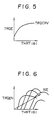
- a target engine torque value TRQE is calculated, as shown in Figure 5, from throttle opening degree THRT using a map of an engine torque curve TRQCRV which has been initially stored in control unit 82.
- a target engine torque value TRQEN is calculated, as shown in Figure 6, from throttle opening degree THRT and engine speed NE using a map of an engine torque curve TRQCRV which has been initially stored in control unit 82.
- the correction factor Ka is calculated only when other conditions such as engine speed NE and vehicle speed V being low, and a pressure value in the clutch being not raised by centrifugal force are met, in addition to the condition that the shift position is N or P, as disclosed in the Figure 1 flowchart, which will be described afterwards. This increases the accuracy of atmospheric pressure detection.
- the numeral 84 denotes a piston of the hydraulic start clutch 62, 86 an annular spring, 88 a first pressure plate, 90 a friction plate, 92 a second pressure plate, 94 an oil pan and 96 an oil filter.
- the belt drive type continuous speed variable transmission is designed such that the oil pump 28 located on the rotational shaft 16 is activated in accordance with the actuation of the rotational shaft 16 and the oil is taken in from the oil pan 94 at the bottom of the transmission through the oil filter 96.
- the pump pressure is controlled by the line pressure control valve 44 to produce the desired line pressure. If a large quantity of oil is permitted to escape through this line pressure control valve 44 into a reservoir, the line pressure becomes low. As the amount of escaping oil becomes smaller, the line pressure becomes higher.
- the continuous speed variable transmission 2 is hydraulic controlled and at the same time, proper line pressure for holding the belt and transmitting torque, primary pressure for changing the gear ratio, and clutch pressure for reliably connecting the clutch plates are respectively secured in accordance with commands from the control unit 82 to the electromagnetic valves 50, 42 and 58.
- a program for controlling the engine revolution of the belt drive type continuous speed variable transmission 2 is started at 100 by actuation of the internal combustion engine (not shown), and it is judged (i.e. determined) at 102 whether the shift position is N or P.
- next step 104 compares the engine speed NE with an established engine speed Na which is trially established by the engine speed NE, and if the judgement at 102 is NO, then an engine torque correction step 112 (which will be described below) is executed.
- the atmospheric pressure Pa is calculated at 108 from an output voltage from the pressure sensor 68.
- the target engine torque value is then multiplied by this correction factor Ka at 112 to correct the engine torque.
- the target engine torque TRQE is calculated at 200 using the map (see Figure 5) of the torque curve TRQCRV in accordance with the detection signal of the throttle opening degree ( ⁇ ) of the carburetor.
- This final engine torque TRQEZ is feed forward processed (204).
- a speed loop operation is performed at 206 with the throttle opening degree ⁇ of the carburetor and the engine speed.
- the result of the speed loop operation is applied to the final engine torque TRQEZ as shown at 208.
- a clutch pressure loop operation 210 is performed based on the clutch pressure.
- a solenoid duty value is calculated at 212, and a clutch control solenoid duty (signal) is output to the clutch pressure control electromagnetic valve 58, which controls the clutch valve 52.
- the target line pressure is established at 304 based on this final engine torque TRQENZ, the belt ratio and, for example, oil temperature.
- a line pressure control solenoid duty value is determined based on this target line pressure and is output to the line pressure control electromagnetic valve 50, which controls the line pressure valve 44. The difference between the target line pressure and the clutch pressure is fed back.
- the solenoid is controlled by computing the duty rate with reference to the target line pressure value and the pressure - solenoid duty map which have been decided upto "304" and thus, the switch SW1 is in the "open" position.
- Atmospheric pressure is detected by the absolute pressure detection type pressure sensor 68, and the clutch pressure and line pressure can be corrected to proper levels using such detected atmospheric pressure.
- acceleration, ascending ability on an uphill road and traveling ability can be maintained in good condition in accordance with the atmospheric pressure.
- the vehicle driver will not think that the vehicle lacks in power, which is advantageous in actual practice.
- the above-described system using the absolute pressure detection type pressure sensor can be easily implemented by adding two additional programs for controlling detection of atmospheric pressure and for torque correction calculation.
- the construction does not become complicated, and manufacturing cost can be maintained low and thus economically advantageous.
Landscapes
- Engineering & Computer Science (AREA)
- Mechanical Engineering (AREA)
- General Engineering & Computer Science (AREA)
- Transportation (AREA)
- Chemical & Material Sciences (AREA)
- Combustion & Propulsion (AREA)
- Physics & Mathematics (AREA)
- Fluid Mechanics (AREA)
- Automation & Control Theory (AREA)
- Control Of Transmission Device (AREA)
- Control Of Driving Devices And Active Controlling Of Vehicle (AREA)
- Hydraulic Clutches, Magnetic Clutches, Fluid Clutches, And Fluid Joints (AREA)
Claims (2)
- Steuervorrichtung für ein stufenloses Getriebe zum Steuern einer kontinuierlich variablen Übertragungsgeschwindigkeit des Getriebes (2) mit einem Riemen (2A), der um einstellbare Scheiben (4, 10) geschlungen ist und in den betreffenden Nuten dieser Scheiben liegt, die zwischen den relativ zueinander beweglichen Scheibenelementen (6, 8; 12, 14) ausgebildet sind, und mit einer Einrichtung zum Ändern des Riemenverhältnisses einschließlich einer Einrichtung zum Vergrößern und Verkleinern des Radius der Riemenumschlingung durch entsprechendes Verringern und Vergrößern der Breite der Nuten, umfassend einen Drucksensor (68) von der Art einer Absolutdruckfeststellung zum Feststellen des Atmosphärendrucks und eine Steuereinrichtung (82) zum Feststellen des Atmosphärendrucks über den Drucksensor (68) in Übereinstimmung mit der Schaltstellung des Getriebes (2) und anderer vorbestimmter Bedingungen und zum Korrigieren des Kupplungsdruckes und des Leitungsdruckes auf geeignete Werte auf der Basis des festgestellten atmosphärischen Druckes,
dadurch gekennzeichnet,
daß die Korrektur nur dann durchgeführt wird, wenn der ausgewählte Betriebszustand N oder P (102) ist. - Steuervorrichtung für ein Getriebe nach Anspruch 1, wobei der Drucksensor (68) auch den Öldruck der Vorrichtung ermittelt.
Applications Claiming Priority (2)
| Application Number | Priority Date | Filing Date | Title |
|---|---|---|---|
| JP256340/89 | 1989-09-30 | ||
| JP1256340A JP2863932B2 (ja) | 1989-09-30 | 1989-09-30 | 連続可変変速機制御装置 |
Publications (3)
| Publication Number | Publication Date |
|---|---|
| EP0421183A2 EP0421183A2 (de) | 1991-04-10 |
| EP0421183A3 EP0421183A3 (en) | 1991-10-09 |
| EP0421183B1 true EP0421183B1 (de) | 1994-12-14 |
Family
ID=17291315
Family Applications (1)
| Application Number | Title | Priority Date | Filing Date |
|---|---|---|---|
| EP90117918A Expired - Lifetime EP0421183B1 (de) | 1989-09-30 | 1990-09-18 | Steuerungssystem für ein stufenloses Getriebe |
Country Status (5)
| Country | Link |
|---|---|
| US (1) | US5069083A (de) |
| EP (1) | EP0421183B1 (de) |
| JP (1) | JP2863932B2 (de) |
| KR (1) | KR930004583B1 (de) |
| DE (1) | DE69015087T2 (de) |
Families Citing this family (15)
| Publication number | Priority date | Publication date | Assignee | Title |
|---|---|---|---|---|
| US5214983A (en) * | 1988-07-29 | 1993-06-01 | Honda Giken Kogyo Kabushiki Kaisha | Controlling device for non-stage transmission for vehicle with fault detection |
| JP2739057B2 (ja) * | 1991-12-28 | 1998-04-08 | スズキ株式会社 | 車両用無段変速機のライン圧制御装置 |
| EP0602672B1 (de) * | 1992-12-17 | 1997-04-09 | Honda Giken Kogyo Kabushiki Kaisha | Verfahren und Vorrichtung zur Steuerung des Übersetzungsverhältnisses eines stufenlosen Getriebes |
| JP2878925B2 (ja) * | 1993-03-31 | 1999-04-05 | 本田技研工業株式会社 | ベルト式無段変速機のプーリ側圧制御装置 |
| US5470288A (en) * | 1993-10-06 | 1995-11-28 | Ford Motor Company | Engine torque compensation shift scheduling of an automatic transmission for motor vehicles |
| US5475590A (en) * | 1993-10-22 | 1995-12-12 | Ford Motor Company | Automatic transmission torque converter bypass clutch control using engine torque compensation |
| EP0727598B1 (de) * | 1995-01-26 | 1998-08-12 | Honda Giken Kogyo Kabushiki Kaisha | Steuergerät für Getriebe |
| US20080182715A1 (en) * | 2006-12-29 | 2008-07-31 | Mike Dickinson | Automotive-transmission clutch-pressure duration |
| US8185285B2 (en) * | 2008-04-08 | 2012-05-22 | GM Global Technology Operations LLC | Transmission hydraulic pressure sensor based altitude measurement |
| KR101326850B1 (ko) * | 2012-10-04 | 2013-11-11 | 기아자동차주식회사 | 오일펌프 제어 시스템 및 방법 |
| EP2927069B1 (de) * | 2012-11-27 | 2018-05-09 | Nissan Motor Co., Ltd | Fahrzeugsteuerungsvorrichtung und verfahren zur steuerung davon |
| JP6011334B2 (ja) * | 2012-12-28 | 2016-10-19 | スズキ株式会社 | ツインクラッチ式変速機の制御装置 |
| US9945479B2 (en) | 2013-01-30 | 2018-04-17 | Brp-Rotax Gmbh & Co. Kg | Method of operating a vehicle and a vehicle |
| DE102013205798B4 (de) * | 2013-04-02 | 2022-09-29 | Man Truck & Bus Se | Verfahren zum Steuern eines Anfahrvorgangs eines Kraftfahrzeugs |
| CA2937209A1 (en) | 2014-01-31 | 2015-08-06 | Brp-Rotax Gmbh & Co. Kg | Continuously variable transmission and vehicle control methods |
Family Cites Families (20)
| Publication number | Priority date | Publication date | Assignee | Title |
|---|---|---|---|---|
| US3020776A (en) * | 1960-05-25 | 1962-02-13 | Borg Warner | Vacuum refrence control for pressure compensation |
| US3106104A (en) * | 1961-01-25 | 1963-10-08 | Gen Motors Corp | Altitude compensated pressure supply mechanism |
| US3295388A (en) * | 1963-09-05 | 1967-01-03 | Gen Motors Corp | Transmission control |
| US3377922A (en) * | 1965-08-30 | 1968-04-16 | Scovill Manufacturing Co | Ambient pressure compensated transmission throttle valve control |
| US3999449A (en) * | 1975-05-01 | 1976-12-28 | General Motors Corporation | Turbine engine compressor discharge pressure modulated transmission |
| JPS5827421B2 (ja) * | 1978-07-31 | 1983-06-09 | 日産自動車株式会社 | 自動変速機の変速時期制御装置 |
| US4458318A (en) * | 1981-04-24 | 1984-07-03 | Borg-Warner Corporation | Control arrangement for a variable pulley transmission |
| JPS5830554A (ja) * | 1981-07-22 | 1983-02-23 | Toyota Motor Corp | 自動変速機の電子制御方法 |
| US4475416A (en) * | 1982-07-27 | 1984-10-09 | Borg-Warner Corporation | Continuously variable transmission down shift control |
| DE3370679D1 (en) * | 1982-09-22 | 1987-05-07 | Borg Warner | Hydraulic control system for continuously variable transmission |
| US4642068A (en) * | 1983-09-28 | 1987-02-10 | Toyota Jidosha Kabushiki Kaisha | Apparatus for controlling continuously variable transmission |
| JPS6084462A (ja) * | 1983-10-17 | 1985-05-13 | Toyota Motor Corp | 車両用無段変速機のライン圧制御装置 |
| JPS60146949A (ja) * | 1984-01-12 | 1985-08-02 | Toyota Motor Corp | 自動変速制御装置 |
| US4718308A (en) * | 1985-03-29 | 1988-01-12 | Borg-Warner Automotive, Inc. | Hydraulic control system for continuously variable transmission |
| JPS6237228A (ja) * | 1985-08-09 | 1987-02-18 | Honda Motor Co Ltd | 手動変速機のシフト指示方法 |
| US4893526A (en) * | 1986-09-19 | 1990-01-16 | Toyota Jidosha Kabushiki Kaisha | Continuous variable transmission control system |
| JP2784919B2 (ja) * | 1987-08-10 | 1998-08-13 | スズキ株式会社 | 連続可変変速機制御方法 |
| JPH0198753A (ja) * | 1987-10-12 | 1989-04-17 | Honda Motor Co Ltd | 車両用無段変速機の変速制御方法 |
| JP2717253B2 (ja) * | 1988-02-16 | 1998-02-18 | 富士重工業株式会社 | 車両用自動クラッチの制御装置 |
| US4943921A (en) * | 1988-10-24 | 1990-07-24 | Ford Motor Company | Automatic transmission electronic gearshift control having altitude corrected shift criteria |
-
1989
- 1989-09-30 JP JP1256340A patent/JP2863932B2/ja not_active Expired - Lifetime
-
1990
- 1990-09-14 KR KR1019900014557A patent/KR930004583B1/ko not_active Expired - Fee Related
- 1990-09-18 EP EP90117918A patent/EP0421183B1/de not_active Expired - Lifetime
- 1990-09-18 DE DE69015087T patent/DE69015087T2/de not_active Expired - Fee Related
- 1990-09-26 US US07/588,762 patent/US5069083A/en not_active Expired - Fee Related
Also Published As
| Publication number | Publication date |
|---|---|
| EP0421183A3 (en) | 1991-10-09 |
| DE69015087T2 (de) | 1995-05-18 |
| JPH03121350A (ja) | 1991-05-23 |
| DE69015087D1 (de) | 1995-01-26 |
| EP0421183A2 (de) | 1991-04-10 |
| KR910006073A (ko) | 1991-04-27 |
| KR930004583B1 (ko) | 1993-06-01 |
| US5069083A (en) | 1991-12-03 |
| JP2863932B2 (ja) | 1999-03-03 |
Similar Documents
| Publication | Publication Date | Title |
|---|---|---|
| EP0421202B1 (de) | Verfahren zur Steuerung eines stufenlos arbeitenden Getriebes | |
| KR0165149B1 (ko) | 차량용 클러치 제어 장치 | |
| EP0421241B1 (de) | Steuerungsanlage für ein stufenloses Getriebe | |
| US5069083A (en) | Continuous speed variable transmission control apparatus | |
| KR950002002B1 (ko) | 차량의 엔진출력 제어장치 | |
| KR0155610B1 (ko) | 자동변속기부착차량의 클러치제어방법 및 장치 | |
| US6311118B1 (en) | Vehicle speed control system | |
| US7338406B2 (en) | Shift control apparatus and method for belt type continuously variable transmission | |
| CN1971105B (zh) | 用于无级变速器的控制装置 | |
| EP0421231B1 (de) | Steuerungsverfahren für ein stufenloses Getriebe | |
| US5069086A (en) | Belt ratio controller for a continuously vaiable transmission | |
| US5024310A (en) | Clutch pressure control device for continuously variable transmission | |
| US5131297A (en) | Shift control method of continuously variable transmission | |
| KR100340256B1 (ko) | 무단변속기의 변속비제어장치 | |
| EP0421142B1 (de) | Verfahren zur Steuerung der Umdrehungsgeschwindigkeit eines stufenlosen Getriebes | |
| US5012697A (en) | Revolution controller for a continuously variable transmission | |
| JPS60192155A (ja) | 車両用スリツプ防止装置 | |
| JP2929046B2 (ja) | 連続可変変速機の変速制御装置 | |
| JPH0719304A (ja) | 車両用無段変速機のライン圧制御装置 | |
| JP3018002B2 (ja) | 連続可変変速機制御装置 | |
| JP3367565B2 (ja) | 連続可変変速機の変速制御方法 | |
| JPH0739255B2 (ja) | 連続可変変速機のライン圧制御方法 | |
| JP2899760B2 (ja) | 連続可変変速機のライン圧制御方法 | |
| JPH02150553A (ja) | 連続可変変速機のライン圧制御装置 | |
| JPH03121352A (ja) | 連続可変変速機制御方法 |
Legal Events
| Date | Code | Title | Description |
|---|---|---|---|
| PUAI | Public reference made under article 153(3) epc to a published international application that has entered the european phase |
Free format text: ORIGINAL CODE: 0009012 |
|
| 17P | Request for examination filed |
Effective date: 19901227 |
|
| AK | Designated contracting states |
Kind code of ref document: A2 Designated state(s): DE FR GB |
|
| PUAL | Search report despatched |
Free format text: ORIGINAL CODE: 0009013 |
|
| AK | Designated contracting states |
Kind code of ref document: A3 Designated state(s): DE FR GB |
|
| RAP1 | Party data changed (applicant data changed or rights of an application transferred) |
Owner name: SUZUKI MOTOR CORPORATION |
|
| 17Q | First examination report despatched |
Effective date: 19930413 |
|
| GRAA | (expected) grant |
Free format text: ORIGINAL CODE: 0009210 |
|
| AK | Designated contracting states |
Kind code of ref document: B1 Designated state(s): DE FR GB |
|
| REF | Corresponds to: |
Ref document number: 69015087 Country of ref document: DE Date of ref document: 19950126 |
|
| ET | Fr: translation filed | ||
| PLBE | No opposition filed within time limit |
Free format text: ORIGINAL CODE: 0009261 |
|
| STAA | Information on the status of an ep patent application or granted ep patent |
Free format text: STATUS: NO OPPOSITION FILED WITHIN TIME LIMIT |
|
| 26N | No opposition filed | ||
| PGFP | Annual fee paid to national office [announced via postgrant information from national office to epo] |
Ref country code: FR Payment date: 20010911 Year of fee payment: 12 |
|
| PGFP | Annual fee paid to national office [announced via postgrant information from national office to epo] |
Ref country code: GB Payment date: 20010919 Year of fee payment: 12 |
|
| PGFP | Annual fee paid to national office [announced via postgrant information from national office to epo] |
Ref country code: DE Payment date: 20011001 Year of fee payment: 12 |
|
| REG | Reference to a national code |
Ref country code: GB Ref legal event code: IF02 |
|
| PG25 | Lapsed in a contracting state [announced via postgrant information from national office to epo] |
Ref country code: GB Free format text: LAPSE BECAUSE OF NON-PAYMENT OF DUE FEES Effective date: 20020918 |
|
| PG25 | Lapsed in a contracting state [announced via postgrant information from national office to epo] |
Ref country code: DE Free format text: LAPSE BECAUSE OF NON-PAYMENT OF DUE FEES Effective date: 20030401 |
|
| GBPC | Gb: european patent ceased through non-payment of renewal fee |
Effective date: 20020918 |
|
| PG25 | Lapsed in a contracting state [announced via postgrant information from national office to epo] |
Ref country code: FR Free format text: LAPSE BECAUSE OF NON-PAYMENT OF DUE FEES Effective date: 20030603 |
|
| REG | Reference to a national code |
Ref country code: FR Ref legal event code: ST |