EP0452704B1 - Arrangement des machines d'impression - Google Patents
Arrangement des machines d'impression Download PDFInfo
- Publication number
- EP0452704B1 EP0452704B1 EP91104634A EP91104634A EP0452704B1 EP 0452704 B1 EP0452704 B1 EP 0452704B1 EP 91104634 A EP91104634 A EP 91104634A EP 91104634 A EP91104634 A EP 91104634A EP 0452704 B1 EP0452704 B1 EP 0452704B1
- Authority
- EP
- European Patent Office
- Prior art keywords
- press
- further unit
- printing
- driving motor
- control
- Prior art date
- Legal status (The legal status is an assumption and is not a legal conclusion. Google has not performed a legal analysis and makes no representation as to the accuracy of the status listed.)
- Expired - Lifetime
Links
- 230000008878 coupling Effects 0.000 claims description 7
- 238000010168 coupling process Methods 0.000 claims description 7
- 238000005859 coupling reaction Methods 0.000 claims description 7
- 239000000463 material Substances 0.000 claims description 5
- 238000012545 processing Methods 0.000 claims description 4
- 238000009434 installation Methods 0.000 claims 15
- 239000011248 coating agent Substances 0.000 description 11
- 238000000576 coating method Methods 0.000 description 11
- 238000010586 diagram Methods 0.000 description 11
- 238000001816 cooling Methods 0.000 description 6
- 230000001105 regulatory effect Effects 0.000 description 6
- 238000004026 adhesive bonding Methods 0.000 description 5
- 230000008901 benefit Effects 0.000 description 4
- 230000006872 improvement Effects 0.000 description 4
- 230000008859 change Effects 0.000 description 3
- 230000000694 effects Effects 0.000 description 3
- 238000004519 manufacturing process Methods 0.000 description 3
- 239000003292 glue Substances 0.000 description 2
- 230000003993 interaction Effects 0.000 description 2
- 230000004048 modification Effects 0.000 description 2
- 238000012986 modification Methods 0.000 description 2
- 238000004806 packaging method and process Methods 0.000 description 2
- 230000001360 synchronised effect Effects 0.000 description 2
- 238000006243 chemical reaction Methods 0.000 description 1
- 238000005520 cutting process Methods 0.000 description 1
- 230000001419 dependent effect Effects 0.000 description 1
- 238000013461 design Methods 0.000 description 1
- 238000011161 development Methods 0.000 description 1
- 230000018109 developmental process Effects 0.000 description 1
- 238000002372 labelling Methods 0.000 description 1
- 238000000034 method Methods 0.000 description 1
- 238000010422 painting Methods 0.000 description 1
- 230000008569 process Effects 0.000 description 1
Images


Classifications
-
- B—PERFORMING OPERATIONS; TRANSPORTING
- B41—PRINTING; LINING MACHINES; TYPEWRITERS; STAMPS
- B41F—PRINTING MACHINES OR PRESSES
- B41F13/00—Common details of rotary presses or machines
- B41F13/08—Cylinders
- B41F13/10—Forme cylinders
- B41F13/12—Registering devices
-
- B—PERFORMING OPERATIONS; TRANSPORTING
- B65—CONVEYING; PACKING; STORING; HANDLING THIN OR FILAMENTARY MATERIAL
- B65H—HANDLING THIN OR FILAMENTARY MATERIAL, e.g. SHEETS, WEBS, CABLES
- B65H23/00—Registering, tensioning, smoothing or guiding webs
- B65H23/04—Registering, tensioning, smoothing or guiding webs longitudinally
- B65H23/18—Registering, tensioning, smoothing or guiding webs longitudinally by controlling or regulating the web-advancing mechanism, e.g. mechanism acting on the running web
- B65H23/188—Registering, tensioning, smoothing or guiding webs longitudinally by controlling or regulating the web-advancing mechanism, e.g. mechanism acting on the running web in connection with running-web
- B65H23/1882—Registering, tensioning, smoothing or guiding webs longitudinally by controlling or regulating the web-advancing mechanism, e.g. mechanism acting on the running web in connection with running-web and controlling longitudinal register of web
- B65H23/1886—Synchronising two or more webs
-
- B—PERFORMING OPERATIONS; TRANSPORTING
- B65—CONVEYING; PACKING; STORING; HANDLING THIN OR FILAMENTARY MATERIAL
- B65H—HANDLING THIN OR FILAMENTARY MATERIAL, e.g. SHEETS, WEBS, CABLES
- B65H2301/00—Handling processes for sheets or webs
- B65H2301/40—Type of handling process
- B65H2301/41—Winding, unwinding
- B65H2301/414—Winding
- B65H2301/4148—Winding slitting
Definitions
- the invention relates to a printing press system, according to the preamble of claim 1.
- the object of the invention is to design a printing press system having a plurality of printing presses more flexibly with regard to the production variants, without increasing the outlay on additional units, the individual printing presses being capable of being operated independently of one another and being able to be placed freely with respect to their spatial arrangement and distance from one another.
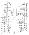
- FIG. 1 shows a first exemplary embodiment of a printing press system according to the invention.
- Two rotary printing presses 1 and 11, each complete and therefore operable independently of one another, are set up at a distance from one another.
- the first printing press 1 has printing units 2 to 5, the precise configuration of which is not important for the present invention and which are therefore not described in detail, as well as a coating unit 6, a dryer 7, a cooling unit 8 and a folder 9. Furthermore, the printing press 1 has a first drive motor 41, a second drive motor 42, a third drive motor 43, a first drive shaft 25 which is arranged along the printing units 2 to 5 and is driven by the drive motor 41, a second drive shaft 26 which runs along the cooling unit 8 and the folder 9 is arranged and driven by the drive motor 43, and coupling devices 27 to 32, with which each of the units 2 to 6, 8 and 9 are coupled individually and independently of the respective other units to the respective drive shaft 25 or 26 can on.
- the coating unit 6 is driven by the drive motor 42.
- a paper web 45 as an example of a printing material web to be printed runs through the individual units in the manner explained below.
- the second printing press 11 has four printing units 12, 13, 14 and 15, the exact configuration of which is not important for the present invention and which are therefore not described in detail, as well as a dryer 16, a cooling unit 17 and two different folders 18 and 19, such as a drum folder and a valve folder.
- the printing press 11 has a fourth drive motor 44, a third drive shaft 33 arranged along the second printing press 11, via which the printing units 12 to 15, the dryer 16, the cooling unit 17 and the two folders 18 and 19 are driven by the drive motor 44, and Coupling devices 34 to 40, with which each of the units 12 to 19 can be coupled individually and independently of the other units to the drive shaft 33.
- a paper web 46 as an example of a printing material web to be printed runs through the individual units in the manner explained below.
- the printing press 1 receives the paper web 45 from a paper supply (not shown), e.g. from a reel changer.
- the paper web 45 passes through the printing units 2 to 5 in a manner specified for the special application.
- the paper web 45 is guided past the coating unit 6 via web guiding elements, specifically guide roller arrangements 51 and 52, and passed into the dryer 7. Subsequently, the paper web 45 passes through the cooling unit 8 and the folder 9.
- the printing press 11 receives the paper web 46 from a paper supply (not shown), for example from a reel changer.
- the paper web 46 passes through the printing units 12 to 15 in a manner specified for the special application.
- the paper web 46 is diverted away from the printing machine 11 and to the coating unit 6 of the printing machine 1 via web guide elements, specifically a guide roller arrangement 47.
- the paper web 46 runs over further web guide elements, specifically a guide roller arrangement 48, into the coating unit 6 and over one Guide roller assembly 49 out of this.
- the paper web 46 is then returned to the printing press 11 and passed into the dryer 16 via a guide roller arrangement 50. Subsequently, the paper web 46 passes through the cooling unit 17 and the folders 18 and 19.
- the web guidance within the folders 18 and 19 can either take place along the path shown as a solid line in FIG. 1, which corresponds to folding the entire web 46 twice.
- the web 46 can be cut in a longitudinal cutting device 11 into two or more partial webs, of which at least one partial web is guided along the path shown as a solid line and thereby folded twice and of which the remaining partial webs are guided along the path shown as a dashed line and be folded once.
- the further unit 6, the coating unit can be used, for example, in cases in which a product with coating is to be produced which, because of the required folding devices 18 and 19, cannot be printed on the printing press 1.
- each of the machines 1 and 11 would have to have a coating unit and two folders in order to maintain the variety of products.
- the control of the individual printing presses of the printing press system takes place by means of a synchronization device 10.
- the synchronization device 10 has the function of coupling or coupling the individual units of the printing presses 1 and 11 and any further printing presses of the printing press system to the respective drive shaft or the respective individual drive in a changeable, predetermined manner . separate from this and so - regardless of the location of the individual units within the printing press system and in particular regardless of their spatial assignment to a specific printing press - to effect a functional assignment of one or more units of a printing press to another printing press and the speed to regulate the different motors.
- the synchronization device 10 has a respective plurality of controllers, microprocessors and further control devices, not shown, e.g. for the coupling devices, which, depending on the interconnection of the printing presses, can be connected to one another in different ways and combined to form control circuits.
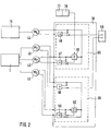
- FIG. 2 shows a block diagram of a synchronization device 10 for the printing press system shown in FIG. 1.
- the synchronization device 10 has a first control circuit 65 and a second control circuit 66.
- Their control function essentially consists in coupling the individual units of the printing presses 1 and 11 to the respective drive shaft 25, 26 and 33, respectively, or separating them from the respective drive shaft, as well as the speed of the drive motors 41 to 44, hereinafter briefly referred to as motors 41 to 44 to regulate.
- the printing press 11 is driven holistically by the motor 44, while in the printing press 1 the units 2 to 5 are driven by the motor 41, the unit 6 by the motor 42 and the units 8 and 9 by the motor 43.
- Motors 42 and 44 are connected to control circuit 65, while motors 41 and 43 are connected to control circuit 66.
- the two control circuits 65 and 66 perform the speed control and synchronization of the motors 42 and 44 or 41 and 43.
- a predefined, ie first, external setpoint for the speed of the motor 44 is entered on a setpoint input device 55, for example a keypad or a data reader. This setpoint is given to an input of a controller 56. The actual value of the speed of the motor 44 is fed back to another input of the controller 56. The controller 56 forms a controlled variable from the difference between the actual value and the desired value and effects a change in the speed of the motor 44 in a manner known per se.
- a controller 57 is provided for regulating the speed of the motor 42. The controller 57 receives the actual speed values of the motors 42 and 44 as input variables as well as an additional one described below Controlled variable. The controller 57 forms an output value from these input values, on the basis of which the speed of the motor 42 changes in a manner known per se, that is to say it is matched to the speed of the motor 44.
- the speed of the motor 41 is regulated by means of a controller 58.
- the controller 58 receives as input variables via the setpoint input device 55 a second external setpoint for the speed of the motor 41 and the actual speed of the motor 41.
- the controller 58 forms the difference between Actual value and setpoint are a controlled variable and cause a change in the speed of the motor 41 in a manner known per se.
- a controller 59 is provided for regulating the speed of the motor 43.
- the controller 59 receives the actual speed values of the motors 41 and 43 as well as an additional control variable described below as input variables. From these input values, the controller 59 forms an output variable on the basis of which the speed of the motor 43 changes in a manner known per se, i.e. is matched to the speed of the motor 41.
- Each of the four motors 41 to 44 is subjected to reactions which come from the units driven by it.
- the actual speed values of the four motors 41 to 44 are given to input connections of a microprocessor 61 or 62.
- the microprocessor 61 then calculates an additional controlled variable for the controller 57 by means of an algorithm that is created in it and taking into account the input variables mentioned.
- the microprocessor 62 calculates an additional controlled variable for the controller 59.
- the control circuits 65 and 66 described above are each constructed according to the principle of the master / slave drive: one of the two drives to be controlled, namely the motor 44 in relation to the circuit 65 and the motor 41 in relation to the circuit 66, is called Considered master drive; consequently, an external setpoint is supplied to the respectively assigned controller, that is, controller 56 or controller 58.
- the respective other drive, that is Motor 42 or motor 43 are then a slave drive, the speed of which is regulated as a function of the actual speed of the master drive.
- the two control circuits 65 and 66 are thus able to control the motors 42 and 44 or 41 and 43 of the printing presses 1 and 11 with respect to their speed so that the unit 6 of the printing press 1 with the units 12 to 19 of the printing press 11th is synchronized and that the unit 8 is synchronized with the unit 5 as long as the printing press 1 works without the unit 6.
- the block diagram of the synchronization device 10 shown in FIG. 2 shows only the controllers and microprocessors required in the application example of FIG. 1. It is obvious to a person skilled in the art to equip the synchronization device 10 with any desired plurality of components of the type of the controller 56, the controller 57 or the microprocessor 61 and to make them interlinkable in a variable manner, in order, for example, to operate both printing presses with all the aggregates and to process the respective printed products after the aggregate 9 or 19 separately or else together and, depending on this, to synchronize the motors 42 and 43 to the motor 41 or the motors 42, 43 and 44 to the Synchronize motor 42.
- the exact number of the respective components depends on how many printing machines the printing press system comprises and how many motors are to be controlled in total.
- An improvement in the control of the speed of the motor 42 can be achieved in that an electrical signal is generated by means of a sensor arranged on the coating unit 6, such as, for example, a register mark scanner 77, and a computing and control device 78 connected downstream thereof Paper web 46 corresponds to applied register marks and which is supplied to the microprocessor 61 as an additional control variable.
- a sensor arranged on the coating unit 6 such as, for example, a register mark scanner 77, and a computing and control device 78 connected downstream thereof Paper web 46 corresponds to applied register marks and which is supplied to the microprocessor 61 as an additional control variable.
- Such an improvement in the regulation of the speed of the motor 42 is particularly advantageous if the coating unit 6 is arranged at a relatively large distance from the printing press 11 and if one registering painting is of particular importance. If another unit is functionally assigned to the printing press 11 instead of the coating unit 6, the same improvement in the control can be achieved by using a different type of sensor and a correspondingly designed computing and control device.
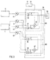
- FIG. 3 shows a block diagram of a modified embodiment of the synchronization device 10 shown in FIG. 2.
- the circuit according to FIG. 3 differs from the circuit according to FIG. 2 in that in the two control circuits 165 and 166 the first and the second external Setpoint is supplied to both controllers. Otherwise, the two circuits 165 and 166 correspond to the circuit 65 and the circuit 66 according to FIG. 2.
- the circuit arrangement according to FIG. 3 is constructed according to the principle of the follower / slave drive and has the advantage over the circuit arrangement according to FIG.
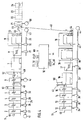
- Fig. 4 shows a schematic representation of a second embodiment of a printing press system according to the invention.
- the printing presses 1 and 11 largely correspond to the printing presses 1 and 11 from the first exemplary embodiment with regard to their operability and the units from which they are composed. Therefore, a detailed description is omitted here again.
- the features shown in FIG. 4 have the same reference numerals as the corresponding features from FIG. 1.
- the printing press 1 has an additional unit 21, for example a glue unit, after the folder 9.
- the printing press 1 can be used instead of or together with the gluing unit 21, specifically in each Appropriate order, one or more of the following units are spatially assigned: a perforating device 20, a stacker 22, a printed product feed device 23 for feeding the semi-finished or finished printed products to a further processing station and a further processing system 24, such as a packaging system.
- a perforating device 20 for feeding the semi-finished or finished printed products to a further processing station
- a further processing system 24 such as a packaging system.
- Other units provided for their functional assignment to several printing presses due to their comparatively low average utilization can also be spatially assigned to the printing press 1.
- the printing press 1 receives from a paper supply (not shown), e.g. a roll changer, a paper web 45.
- the paper web 45 passes through the printing press 1 completely.
- the exact course of the paper web 45 within the printing units 2 to 5 is to be defined in the special application.
- the printing machine 11 receives from a paper supply (not shown), e.g. a roll changer, a paper web 46.
- the paper web 46 passes through the printing press 11 completely, the exact course of the paper web 46 within the printing units 12 to 15 being determined in the special application.
- the paper web 46 is fed to the gluing unit 21 of the printing machine 1 via the guide roller arrangements 54 of the printing press 11 and 53 of the printing press 1 serving as deflection means and passes through the gluing unit 21 simultaneously with the paper web 45.
- Both paper webs are still brought together in the gluing unit 21 and in further subsequent units, not shown in FIG. 4, such as, for example a further folder or labeling and packaging devices, processed further.
- the control of the individual units of the two printing presses 1 and 11, including the gluing unit 21, and the regulation of the drive motors 41 to 44 takes place by means of the synchronization device 10, with which the two printing presses 1 and 11 and downstream devices are connected.
- FIG. 5 shows a block diagram of a first synchronization circuit 10 for the one shown in FIG. 4 Printing press system.
- this synchronization circuit largely corresponds to the circuit shown in FIG. 2, which is why the same reference numerals are used in FIG. 5 for the features corresponding to the features from FIG. 2.
- 5 also shows only the controllers and microprocessors required in the application example according to FIG. 4, without generally wanting to limit the number of these components to the amount shown.
- the units of the printing press 1 are driven by the motors 41 to 43, while the units of the printing press 2 are driven by the motor 44.
- the speed control of the motors 41 to 44 takes place via a control circuit 67.
- the glue unit 21 is driven by a motor 69.
- the motor 69 is also controlled via the control circuit 67.
- the control circuit 67 has an associated controller 56, 57, 58, 59 and 60 and microprocessors 61 to 64 for each motor.
- a setpoint input device 55 is provided for the external input of a setpoint for the speed control of the motor 69.
- the speed setpoint entered on the device 55 is fed to the controller 56 as the first input variable.
- the controller 56 receives the actual value of the speed of the motor 69 as feedback.
- the regulator 56 From the difference between the two input variables, the regulator 56 forms a controlled variable with which a change in the speed of the motor 69 is effected in a manner known per se.
- the controllers 57 to 60 receive the respective actual speed of the associated motor as the first control variable and the actual speed of the motor 69 as the second control variable.
- the actual speed value of the motor 69 is also fed to the microprocessors 61 to 64 in a corresponding manner on the basis of algorithms which can be changed in them and which are adapted to the special configuration of the printing press system, each calculate an additional control variable for the controllers 57 to 60 from the actual speed values as the respective third control variable.
- control circuit 67 it is possible to match the speeds of the motors 41 to 44 as best as possible to the actual speed of the motor 69, taking into account the repercussions to which the motors are exposed.
- FIG. 6 shows a block diagram of a second synchronization circuit 10 for the printing press system shown in FIG. 4.
- this synchronization circuit largely corresponds to the circuit shown in FIG. 5, which is why the same reference numerals are used in FIG. 6 for the features corresponding to the features from FIG. 5.
- the synchronization circuit 10 shown in FIG. 6 differs from the circuit shown in FIG. 5 in that the speed setpoint input via the setpoint input device 55 is supplied to all microprocessors 61 to 64 and 70 at the same time and in that the motors 41 to 44 are controlled and 69 is based on the same setpoint.
- An improvement in the control of the individual motors can be achieved in that sensors 71 to 75 are arranged at locations which are characteristic of the web path of the paper web 45 or the paper web 46 and that the signals generated by the sensors 71 to 75 are sent to the respective microprocessor 70, 61 , 62, 63 and 64 are supplied as an additional control variable.
- the control circuit in FIG. 6 is provided with the reference number 68.
- the motors 41 to 44 and 69 can be controlled so that all units driven by these motors interact optimally.
- the use of sensors 71 to 75 ensures that motors 41 to 44 and 69 are not exposed to the risk otherwise present of speeding apart in spite of the common setpoint specification. Irrespective of this, a circuit arrangement according to FIG. 6 has the advantage over the circuit arrangement according to FIG.
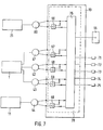
- FIG. 7 shows a block diagram of a third synchronization circuit 10 for the printing press system shown in FIG. 4.
- this circuit has a microprocessor 76.
- the microprocessor 76 has a variably predetermined algorithm which links the external speed setpoint input via the setpoint input device 55 and the actual speed values supplied by the motors 41 to 44 and 69 and derives internal setpoints for the controllers 56 to 60 therefrom.
- measured values can also be taken into account, which are detected by sensors 71 to 75 and fed to microprocessor 76.
- the sensors 71 to 75 correspond in type and use to the sensors 71 to 75 in FIG. 6, which is why they are provided with the same reference numerals in both figures.
- the microprocessor 76, the regulators 56 to 60 and the further components, not shown, which are required for the operation and the interconnection of the regulators and the microprocessor are combined in FIG. 7 in a regulating circuit 79.
- the microprocessor 76 has the same function as the microprocessors 61 to 64 and 70 from the synchronization device 10 according to FIG. 6. In addition, it is able to coordinate the individual control sequences of the motors 41 to 44 and 69 with one another, so that the after Principle of the follower / follower drive, the synchronization device 10 regulates the speeds of the motors 41 to 44 and 69 with the least possible overrun, and in particular ensures that the speeds of the individual motors do not diverge.
- a printing press system it can be achieved in a particularly advantageous manner that all units of the Printing presses belonging to printing presses as well as aggregates subordinate to these printing presses can be used in an optimal manner.
- the configuration of the printing press system can be adapted quickly and easily to the characteristics of the print job to be carried out by means of functional or effective connection, and that units that are not constantly required, such as varnishing devices, therefore do not have to be installed on every printing press.
- the printing press system according to the invention is characterized by an advantageous combination of mechanical control and electronic control.
- the extremely economical mechanical control of the drive of the printing units is supplemented by electronic control of other units and electronic control of the interaction of the printing presses belonging to the printing press system.
- the electronic regulation of the interaction of the respective printing presses is particularly advantageous in that it opens up greater adaptability to the local or operational requirements of the respective production site when installing the individual printing presses or the aggregates of the respective printing presses, as does mechanical synchronization, e.g. by means of a transverse shaft connecting the printing machines or an overlong longitudinal shaft.
- the printing press system according to the invention offers the advantage of an extremely flexible configuration without having to accept an expensive control device, as would be the case with a single drive of all units with purely electronic control.
Landscapes
- Engineering & Computer Science (AREA)
- Mechanical Engineering (AREA)
- Inking, Control Or Cleaning Of Printing Machines (AREA)
- Rotary Presses (AREA)
Claims (13)
- Installation de machines à imprimer, composée de plusieurs machines à imprimer (1, 11) qu'on peut faire travailler aussi bien indépendamment les unes des autres qu'en commun, qui présentent chacune des groupes imprimants (2 à 5, 12 à 15) et des groupes tels que des séchoirs (7, 16), des refroidisseurs (8, 17) et des plieuses (9, 18, 19) et à la première (1) desquelles un groupe additionnel (6 ; 20 à 24) est associé dans l'espace, caractérisée en ce que le groupe additionnel (6 ; 20 à 24) peut être associé fonctionnellement à une deuxième machine à imprimer (1, 11) qui ne comporte pas ce groupe additionnel (6 ; 20 à 24), en ce qu'il est prévu des moyens (47, 48) servant à acheminer, à la cadence du défilement de la bande, une bande (46) de support d'impression de la deuxième machine à imprimer (11) au groupe additionnel (6 ; 20 à 24) fonctionnellement associé, appartenant à la première machine à imprimer (1) et en ce qu'un moteur d'entraînement individuel (42 ; 69) du groupe additionnel (6 ; 20 à 24) fonctionnellement associé peut être synchronisé à la deuxième machine à imprimer (1, 11) au moyen d'un dispositif de synchronisation électrique (10).
- Installation de machines à imprimer selon la revendication 1, caractérisée en ce que le groupe additionnel (6 ; 20 à 24) est un dispositif de vernissage (6), un dispositif de perforation (20), un dispositif d'encollage (21), un dispositif de dépose croisée (22), un dispositif (23) d'acheminement du produit imprimé, ou une installation (24) de traitement ultérieur, ou un autre dispositif de travail ou de transformation d'une bande (46) de support d'impression.
- Installation de machines à imprimer selon la revendication 1 ou 2, caractérisée en ce que, dans au moins deux des machines à imprimer (1, 11), les groupes imprimants (2 à 5, 12 à 15), les refroidisseurs (8, 17), les plieuses (9, 18, 19) et les groupes additionnels (6 ; 20 à 24) qui peuvent être associés fonctionnellement à une autre machine à imprimer, peuvent être reliés à un moteur d'entraînement correspondant (41 à 44 ; 69) individuellement et indépendamment les unes des autres, au moyen d'un nombre correspondant de dispositifs d'embrayage (27 à 32, 34 à 40).
- Installation de machines à imprimer selon une des revendications 1 à 3, caractérisée en ce qu'un premier moteur d'entraînement (41) est relié à un premier arbre d'entraînement (25) disposé le long de la première machine à imprimer (1), en ce qu'un deuxième moteur d'entraînement (42) est relié au groupe additionnel (6) de la première machine à imprimer (1), en ce qu'un troisième moteur d'entraînement (43) est relié à un deuxième arbre d'entraînement (26) disposé le long de la première machine à imprimer (1), en ce les groupes imprimants (2 à 5) de la première machine à imprimer (1) peuvent être reliés au premier arbre d'entraînement (25) individuellement et indépendamment les uns des autres et en ce que le refroidisseur (8) et la plieuse (9) de la première machine à imprimer (1) peuvent être reliés au deuxième arbre d'entraînement (26).
- Installation de machines à imprimer selon une des revendications 1 à 4, caractérisée en ce qu'il est prévu des éléments de guidage de la bande (47 à 50) en qualité de moyens (47 à 50) pour l'acheminement de la bande (46) de support d'impression de la deuxième machine à imprimer (11) au groupe additionnel (6) associé fonctionnellement.
- Installation de machines à imprimer selon une des revendications 1 à 5, caractérisée en ce que le dispositif de synchronisation (10) est réalisé de manière à pouvoir commander et régler sélectivement chaque machine à imprimer (1, 11) individuellement et seule ou simultanément avec au moins une autre machine à imprimer de l'installation de machines à imprimer ou avec au moins deux machines à imprimer (1, 11) en combinaison, et avec association fonctionnelle d'au moins un groupe additionnel (6) associé dans l'espace à une machine à imprimer (1) à une autre machine à imprimer (11).
- Installation de machines à imprimer selon la revendication 6, caractérisée en ce que le dispositif de synchronisation (10) comprend un dispositif (55) pour l'introduction d'une valeur de consigne externe.
- Installation de machines à imprimer selon la revendication 6 ou 7, caractérisée en ce que le dispositif de synchronisation (10) comprend un premier (65) et un deuxième (66) circuits de régulation, dont le premier circuit de régulation (65) comprend deux régulateurs (56, 57) pour la régulation du moteur d'entraînement (44) de la deuxième machine à imprimer (11) et du moteur d'entraînement (42) du groupe additionnel (6) associé fonctionnellement à cette machine à imprimer (11), et un microprocesseur (61) au moyen duquel est superposée, à la régulation du moteur (42) du groupe (6) associé fonctionnellement, une régulation exécutée sur la base d'une valeur de consigne interne, déterminée à partir de données de travail du moteur d'entraînement (44) de la deuxième machine à imprimer (11), et sur la base d'une réinjection de données de travail du moteur d'entraînement (42) du groupe additionnel (6) associé fonctionnellement, et le deuxième circuit de régulation (66) comprend deux régulateurs (58, 59) pour la régulation des autres moteurs d'entraînement (42, 43) de la première machine à imprimer (1) qui présente le groupe additionnel (6), et un microprocesseur (62) au moyen duquel est superposée à la régulation d'au moins un (43) de ces autres moteurs d'entraînement (41, 43), une régulation exécutée sur la base d'une valeur de consigne interne, déterminée à partir de données de travail de tous ces autres moteurs d'entraînement (41, 43), le régulateur (56) du moteur d'entraînement (44) de la deuxième machine à imprimer (11) et le régulateur (58) d'un (41) des autres moteurs d'entraînement (41, 43) de la machine à imprimer (1) qui comprend le groupe additionnel (6) recevant chacun une valeur de consigne externe.
- Installation de machines à imprimer selon la revendication 6 ou 7, caractérisée en ce que le dispositif de synchronisation (10) comprend un circuit (67) comportant un régulateur (56) pour la régulation d'un moteur d'entraînement (69) d'un groupe additionnel (21) associé dans l'espace à une machine à imprimer, et une pluralité de régulateurs (57 à 60), et une pluralité de microprocesseurs (61 à 64) pour la régulation des moteurs d'entraînement (41, 42, 43, 44) de la machine à imprimer (1) à laquelle le groupe additionnel (21) est associé dans l'espace et à la machine à imprimer (11) à laquelle le groupe additionnel (21) est associé fonctionnellement, le régulateur (56) du moteur d'entraînement (69) du groupe additionnel (21) recevant une valeur de consigne externe, les régulateurs (57 à 60) des moteurs (41, 42, 43, 44) des machines à imprimer (1, 11) recevant la valeur réelle de la vitesse de rotation du moteur d'entraînement (69) du groupe additionnel (21) en qualité de valeur de consigne interne, et, à la régulation des moteurs d'entraînement (41, 42, 43, 44) des machines à imprimer (1, 11), est superposée, au moyen des microprocesseurs (61 à 64) une régulation exécutée sur la base de valeurs de consignes internes définies à partir de données de travail de tous ces moteurs (41, 42, 43, 43).
- Installation de machines à imprimer selon la revendication 6 ou 7, caractérisée en ce que le dispositif de synchronisation (10) comprend un circuit (68) comportant un régulateur (56) et un microprocesseur (70) pour la régulation d'un moteur d'entraînement (69) d'un groupe additionnel (21) associé dans l'espace à la machine à imprimer (1) et une pluralité de régulateurs (57 à 60) et une pluralité de microprocesseurs (61 à 64) pour la régulation des moteurs d'entraînement (41, 42, 43, 44) de la machine à imprimer (1) à laquelle le groupe additionnel (21) est associé dans l'espace et de la machine à imprimer (11) à laquelle le groupe additionnel (21) est associé fonctionnellement, une unique valeur de consigne externe étant transmise simultanément à tous les microprocesseurs (61 à 64, 70), tous les régulateurs (56 à 60) recevant la valeur de consigne de la vitesse de rotation du moteur d'entraînement correspondant (41 à 44, 69) comme grandeur réglante, cependant qu'à la régulation des moteurs d'entraînement (41 à 44, 69) des machines à imprimer (1, 11) est superposée, au moyen des microprocesseurs (61 à 64, 70), une régulation exécutée sur la base de valeurs de consigne internes définies à partir de données de travail du moteur d'entraînement (41, 42, 43, 44 ou 69) correspondant et d'une autre grandeur réglante, fournie par un dispositif capteur correspondant (71 à 75).
- Installation de machines à imprimer selon la revendication 6 ou 7, caractérisée en ce que le dispositif de synchronisation (10) comprend un circuit (79) comportant un régulateur (56) servant à la régulation d'un moteur d'entraînement (69) d'un groupe additionnel (21) associé dans l'espace à une machine à imprimer, une pluralité de régulateurs (57 à 60) servant à la régulation des moteurs d'entraînement (41, 42, 43, 44) de la machine à imprimer (1) à laquelle le groupe additionnel (21) est associé dans l'espace, et un microprocesseur (76), une valeur de consigne externe étant transmise au microprocesseur (76), tous les régulateurs (56 à 60) recevant la valeur réelle de la vitesse de rotation du moteur d'entraînement qui leur correspond (41 à 44, 69) en tant que grandeur réglante, et cependant qu'à la régulation des moteurs d'entraînement (41 à 44, 69) des machines à imprimer (1, 11) est superposée, au moyen du microprocesseur (76), une régulation exécutée sur la base de valeurs de consigne internes définies à partir des données de travail de tous les moteurs d'entraînement (41, 42, 43, 44, 69).
- Installation de machines à imprimer selon la revendication 11, caractérisée en ce que le dispositif de synchronisation (10) est relié à une pluralité de dispositifs capteurs (71 à 75).
- Installation de machines à imprimer selon une des revendications 1 à 12, caractérisée en ce que le dispositif de synchronisation (10) est relié à un dispositif (77) destiné à palper un marquage de repérage et à une unité arithmétique et logique (78) destinée à calculer une grandeur réglante pour la commande du groupe additionnel (6 ; 20 à 24) associé fonctionnellement à une machine à imprimer (11).
Applications Claiming Priority (2)
| Application Number | Priority Date | Filing Date | Title |
|---|---|---|---|
| DE4012396 | 1990-04-19 | ||
| DE4012396A DE4012396A1 (de) | 1990-04-19 | 1990-04-19 | Druckmaschinenanlage |
Publications (3)
| Publication Number | Publication Date |
|---|---|
| EP0452704A2 EP0452704A2 (fr) | 1991-10-23 |
| EP0452704A3 EP0452704A3 (fr) | 1991-10-30 |
| EP0452704B1 true EP0452704B1 (fr) | 1994-05-04 |
Family
ID=6404604
Family Applications (1)
| Application Number | Title | Priority Date | Filing Date |
|---|---|---|---|
| EP91104634A Expired - Lifetime EP0452704B1 (fr) | 1990-04-19 | 1991-03-25 | Arrangement des machines d'impression |
Country Status (5)
| Country | Link |
|---|---|
| US (1) | US5117753A (fr) |
| EP (1) | EP0452704B1 (fr) |
| JP (1) | JPH04224960A (fr) |
| CA (1) | CA2038570C (fr) |
| DE (2) | DE4012396A1 (fr) |
Cited By (1)
| Publication number | Priority date | Publication date | Assignee | Title |
|---|---|---|---|---|
| CN103158350A (zh) * | 2011-12-15 | 2013-06-19 | 中国科学院沈阳计算技术研究所有限公司 | 通用型商务轮转式印刷机的控制系统 |
Families Citing this family (63)
| Publication number | Priority date | Publication date | Assignee | Title |
|---|---|---|---|---|
| DE4201481A1 (de) * | 1992-01-21 | 1993-07-22 | Heidelberger Druckmasch Ag | Einrichtung zur handhabung von materialbahnen in verarbeitungsmaschinen |
| DE4210989C2 (de) * | 1992-04-02 | 2001-07-12 | Heidelberger Druckmasch Ag | Mehrfachantrieb für eine Bogenrotationsdruckmaschine |
| US6427590B1 (en) | 1992-10-12 | 2002-08-06 | Heidelberger Druckmaschinen Ag | Drive for a printing press with a plurality of printing units |
| DE4241807A1 (de) * | 1992-12-11 | 1994-06-16 | Heidelberger Druckmasch Ag | Antrieb für eine Druckmaschine |
| JPH06320714A (ja) * | 1993-05-14 | 1994-11-22 | Toshiba Mach Co Ltd | 切換式連続運転用印刷機およびその運転方法 |
| DE4318299A1 (de) * | 1993-06-02 | 1994-12-08 | Roland Man Druckmasch | Einziehvorrichtung und Verfahren zum Einzug von Materialbahnen in eine Druckmaschine |
| US5447566A (en) * | 1993-12-27 | 1995-09-05 | Autographic Business Forms, Inc. | Paper coating and drying machine |
| NL9400088A (nl) * | 1994-01-19 | 1995-09-01 | Stork X Cel Bv | Drukinrichting voorzien van verplaatsbare drukeenheid. |
| US6644184B1 (en) * | 1995-02-09 | 2003-11-11 | Man Roland Druckmaschinen Ag | Offset printing machine |
| DE4430693B4 (de) * | 1994-08-30 | 2005-12-22 | Man Roland Druckmaschinen Ag | Antriebe für eine Rollenrotations-Offsetdruckmaschine |
| DE4435429C2 (de) * | 1994-10-04 | 2000-07-06 | Wifag Maschf | Rollenrotationsdruckmaschine |
| US6148724A (en) * | 1994-12-20 | 2000-11-21 | Moore Business Forms, Inc. | Selective flexographic printing |
| US5608639A (en) * | 1995-01-13 | 1997-03-04 | Wallace Computer Services, Inc. | System and method for printing, assembly and verifying a multiple-part printed product |
| JPH08238746A (ja) * | 1995-02-15 | 1996-09-17 | Gimaco Ing Ag Fuer Mas Bau | 1個の設備における複数軸の同期駆動装置 |
| EP0814959B1 (fr) * | 1995-03-18 | 2004-05-26 | Koenig & Bauer Aktiengesellschaft | Procede d'actionnement d'une unite, par ex. une plieuse de presse rotative |
| DE19525169C2 (de) * | 1995-03-18 | 2000-02-03 | Koenig & Bauer Ag | Verfahren zum Antreiben eines Falzapparates |
| DE19516445A1 (de) † | 1995-05-04 | 1996-11-07 | Wifag Maschf | Rotationsdruckmaschine mit frei aufstellbarem Falzapparat |
| US5743184A (en) * | 1997-05-27 | 1998-04-28 | Joe Irace | Gearless printing press |
| US5816152A (en) * | 1997-09-02 | 1998-10-06 | Delaware Capital Formation, Inc. | Reconfigurable printing press |
| DE19742461C2 (de) * | 1997-09-26 | 2001-05-10 | Heidelberger Druckmasch Ag | Vorrichtung zum Antrieb einer Bogendruckmaschine mit Mehrmotorenantrieb |
| JP3180291B2 (ja) * | 1997-11-10 | 2001-06-25 | 株式会社ミヤコシ | フォーム印刷機における用紙テンション制御装置 |
| JPH11187688A (ja) * | 1997-12-22 | 1999-07-09 | Canon Inc | モータ制御方法、モータ制御装置および画像形成装置 |
| EP0950519B1 (fr) * | 1998-04-16 | 2001-08-29 | ABB Industrie AG | Procédé de contrôle automatique du repérage d'impression et de coupe dans des machines d'impression rotatives avec plusieurs bandes |
| US6655285B2 (en) * | 1998-10-23 | 2003-12-02 | Komori Corporation | Method and device for controlling automatic printing plate changing means and folding device status switching device |
| US6387201B1 (en) | 1999-05-14 | 2002-05-14 | Best Cutting Die Company | Rotary hot foil stamping machine |
| DE19959152A1 (de) * | 1999-12-08 | 2001-06-13 | Heidelberger Druckmasch Ag | Einrichtung zur Führung von Materialbahnen in Rotationsdruckmaschinen |
| DE10128122A1 (de) * | 2001-06-09 | 2002-12-12 | Roland Man Druckmasch | Antrieb für einen Falzapparat |
| US6823792B2 (en) * | 2001-07-26 | 2004-11-30 | Heidelberger Druckmaschinen Ag | Multi-motor drive and method for driving a printing press |
| DE10236864B4 (de) | 2002-08-12 | 2007-02-01 | Koenig & Bauer Ag | Heatset-Druckmaschine |
| DE10245962A1 (de) * | 2002-10-02 | 2004-04-15 | Man Roland Druckmaschinen Ag | Verfahren und Vorrichtung zum Regeln des Schnittregisters einer Rollenrotationsdruckmaschine |
| DE10326080A1 (de) * | 2003-06-10 | 2005-01-27 | OCé PRINTING SYSTEMS GMBH | Druckstraße mit Bahnspeichereinheit und Nachverarbeitungssystem |
| WO2005000572A1 (fr) * | 2003-06-23 | 2005-01-06 | The Procter & Gamble Company | Susbstrats lamines a images imprimees et motifs en relief etablis selon une precision elevee |
| CA2529699C (fr) | 2003-06-23 | 2008-11-18 | The Procter & Gamble Company | Procede de realisation d'images imprimees et de motifs en relief a haute precision d'implantation mutuelle sur des substrats etirables |
| DE502004009017D1 (de) | 2003-07-11 | 2009-04-02 | Koenig & Bauer Ag | Rollenrotationsdruckmaschine |
| EP1515364B1 (fr) | 2003-09-15 | 2016-04-13 | Nuvotronics, LLC | Boîtier de dispositif et leurs procédés de fabrication et de test |
| US7044902B2 (en) * | 2003-12-09 | 2006-05-16 | Quad/Tech, Inc. | Printing press folder and folder components |
| CH697884B1 (de) * | 2004-07-13 | 2009-03-13 | Manroland Ag | Rollenrotationsdruckeinheit. |
| DE202004021518U1 (de) | 2004-09-09 | 2008-09-04 | Koenig & Bauer Aktiengesellschaft | Druckmaschinen |
| DE102004051263A1 (de) * | 2004-10-21 | 2006-04-27 | Man Roland Druckmaschinen Ag | Druckmaschinenanordnung |
| PL2067627T3 (pl) * | 2004-10-22 | 2011-07-29 | Sanford Lp | Drukarka |
| DE102004056931A1 (de) * | 2004-11-25 | 2006-06-01 | Man Roland Druckmaschinen Ag | Rollenrotationsdruckmaschine |
| DE102005005401A1 (de) * | 2005-02-05 | 2006-08-10 | Man Roland Druckmaschinen Ag | Rollenrotationsdruckmaschine und Falzapparat |
| EP1888337A1 (fr) * | 2005-04-19 | 2008-02-20 | Koenig & Bauer AG | Installation de machines a imprimer |
| DE102005037731B4 (de) * | 2005-04-19 | 2009-06-04 | Koenig & Bauer Aktiengesellschaft | Druckmaschinenanlagen |
| EP1871602B1 (fr) * | 2005-04-19 | 2013-10-02 | Koenig & Bauer Aktiengesellschaft | Machine d'impression |
| JP4829529B2 (ja) * | 2005-04-28 | 2011-12-07 | 株式会社小森コーポレーション | 印刷機 |
| ES2289859B1 (es) * | 2005-05-13 | 2008-11-16 | Umetal Frontages And Covers International, S.L. | Instalacion de impresion digital de superficies. |
| US7187142B2 (en) * | 2005-05-25 | 2007-03-06 | Rockwell Automation Technologies, Inc. | Motor drive with velocity noise filter |
| US7109670B1 (en) * | 2005-05-25 | 2006-09-19 | Rockwell Automation Technologies, Inc. | Motor drive with velocity-second compensation |
| US8011297B2 (en) | 2005-08-18 | 2011-09-06 | Koenig & Bauer Aktiengesellschaft | Printing machine system |
| US8141485B2 (en) | 2005-08-18 | 2012-03-27 | Koenig & Bauer Aktiengesellschaft | Printing machine system |
| DE102005048472A1 (de) * | 2005-10-07 | 2007-04-12 | Bosch Rexroth Ag | Rotationsdruckmaschine und Verfahren des Betriebs einer Rotationsdruckmaschine |
| EP1960198A1 (fr) | 2005-12-15 | 2008-08-27 | Koenig & Bauer AG | Systeme d'imprimeuses |
| DE502006002191D1 (de) | 2005-12-15 | 2009-01-08 | Koenig & Bauer Ag | Druckmaschinenanlage |
| WO2007068643A1 (fr) | 2005-12-15 | 2007-06-21 | Koenig & Bauer Aktiengesellschaft | Installation de machines d'imprimerie |
| US20080022872A1 (en) * | 2006-07-28 | 2008-01-31 | The Procter & Gamble Company | Apparatus for perforating printed or embossed substrates |
| US7222436B1 (en) | 2006-07-28 | 2007-05-29 | The Procter & Gamble Company | Process for perforating printed or embossed substrates |
| DE102008064635A1 (de) * | 2008-03-05 | 2009-12-10 | Koenig & Bauer Aktiengesellschaft | Druckmaschine und Verfahren zum Betrieb einer Druckmaschine sowie Druckmaschinenanlage und Verfahren zum Betrieb der Druckmaschinenanlage |
| JP2010094858A (ja) * | 2008-10-15 | 2010-04-30 | Komori Corp | 処理機の駆動制御方法及び装置 |
| DE102008056132A1 (de) * | 2008-11-06 | 2010-05-12 | Robert Bosch Gmbh | Verfahren zur Bahnspannungseinstellung |
| NL2019408B1 (nl) | 2017-08-10 | 2019-02-21 | Mps Holding Bv | Samenstel voor het bewerken van een substraatbaan |
| US10319654B1 (en) | 2017-12-01 | 2019-06-11 | Cubic Corporation | Integrated chip scale packages |
| CN112655011A (zh) * | 2018-09-05 | 2021-04-13 | 格柏科技有限公司 | 生产服装的方法及装置 |
Family Cites Families (28)
| Publication number | Priority date | Publication date | Assignee | Title |
|---|---|---|---|---|
| CA623588A (en) * | 1961-07-11 | Electric Eye Equipment Company | Multi-unit printing-press drive | |
| US1307390A (en) * | 1919-06-24 | Ginia | ||
| US971533A (en) * | 1910-02-05 | 1910-10-04 | Goss Printing Press Co Ltd | Printing-machine. |
| GB191305728A (en) * | 1913-03-07 | 1914-03-05 | Goss Printing Press Co England | Improvements in or relating to Printing Machines. |
| US1774779A (en) * | 1926-12-20 | 1930-09-02 | Wood Newspaper Mach Corp | Paper lead for the upper decks of printing presses |
| US1738324A (en) * | 1926-12-30 | 1929-12-03 | Scott Isabella | Multicolor-printing press |
| US1774119A (en) * | 1928-03-26 | 1930-08-26 | Edward A Waller | Printing press |
| US1847708A (en) * | 1930-11-28 | 1932-03-01 | Cottrell C B & Sons Co | Multicolor rotary printing press |
| US1971771A (en) * | 1933-01-05 | 1934-08-28 | Goss Printing Press Co Ltd | Printing press |
| CH201020A (de) * | 1936-10-12 | 1938-11-15 | Matuschke Walter | Druckmaschinenanlage, bestehend aus einer Mehrfarben-Rollenrotationsmaschine und einer Einfarben-Hochdruckrollenrotationsmaschine. |
| GB702603A (en) * | 1950-04-27 | 1954-01-20 | Igranic Electric Co Ltd | Improvements in or relating to electric motor drives for printing presses |
| US2911908A (en) * | 1958-01-22 | 1959-11-10 | Harris Intertype Corp | Printing press |
| US3084621A (en) * | 1960-05-14 | 1963-04-09 | Pietro Guazzo Ing | Process and apparatus for controlling register on rotogravure printing machines |
| US3068787A (en) * | 1960-05-18 | 1962-12-18 | Dall Oglio Giorgio | Device for checking longitudinal registration on machines for performing repetitive operations on a continuous band |
| GB1119142A (en) * | 1965-08-03 | 1968-07-10 | Crabtree & Sons Ltd R | Offset printing press |
| US3556509A (en) * | 1968-08-21 | 1971-01-19 | Harris Intertype Corp | Printed web ribbon registration control system |
| US3605618A (en) * | 1968-11-14 | 1971-09-20 | Herman F Clasen | Reflex detector counter and monitoring system |
| US3717092A (en) * | 1970-11-23 | 1973-02-20 | Harris Intertype Corp | Registering mechanism for printing press |
| DE2122416A1 (de) * | 1971-05-06 | 1972-11-16 | Schnellpressenfabrik Koenig & Bauer AG, 8700 Würzburg | Papierbahnführung in Rollenrotationsdruckmaschinen |
| US4096801A (en) * | 1972-02-01 | 1978-06-27 | Martin John R | Register control method and apparatus |
| US3841216A (en) * | 1972-12-07 | 1974-10-15 | Hamilton Tool Co | Method of and apparatus for correcting deviations in length and registration in a continuous strip of material |
| DE2460612C2 (de) * | 1974-12-20 | 1984-08-09 | M.A.N. Maschinenfabrik Augsburg-Nürnberg AG, 8900 Augsburg | Rollen-Offsetmaschine |
| US4177730A (en) * | 1976-11-04 | 1979-12-11 | Harris Corporation | Method and apparatus for web printing |
| DE2753433C2 (de) * | 1977-11-30 | 1986-02-06 | Windmöller & Hölscher, 4540 Lengerich | Verfahren und Vorrichtung zum Voreinstellen der Formzylinder von Mehrfarbenrollen-Rotationsdruckmaschinen |
| DE3117663C2 (de) * | 1981-05-05 | 1984-09-20 | M.A.N.- Roland Druckmaschinen AG, 6050 Offenbach | Rollenrotationsdruckmaschine |
| DE8314827U1 (de) * | 1983-05-19 | 1985-09-19 | M.A.N.- Roland Druckmaschinen AG, 6050 Offenbach | Rollenrotationsdruckmaschine |
| DE3614624A1 (de) * | 1986-04-30 | 1987-11-05 | Heidelberger Druckmasch Ag | Druckmaschine mit mehreren komponenten, insbesondere druckwerken, anlege- und auslegeeinrichtungen |
| US4785734A (en) * | 1986-11-04 | 1988-11-22 | Fuji Kikai Kogyo Co., Ltd. | Apparatus for controlling paper transfer speed of a printing section of a form printing machine |
-
1990
- 1990-04-19 DE DE4012396A patent/DE4012396A1/de not_active Withdrawn
-
1991
- 1991-03-19 CA CA002038570A patent/CA2038570C/fr not_active Expired - Fee Related
- 1991-03-20 US US07/672,476 patent/US5117753A/en not_active Expired - Fee Related
- 1991-03-25 EP EP91104634A patent/EP0452704B1/fr not_active Expired - Lifetime
- 1991-03-25 DE DE59101539T patent/DE59101539D1/de not_active Expired - Fee Related
- 1991-04-17 JP JP3084996A patent/JPH04224960A/ja active Pending
Cited By (2)
| Publication number | Priority date | Publication date | Assignee | Title |
|---|---|---|---|---|
| CN103158350A (zh) * | 2011-12-15 | 2013-06-19 | 中国科学院沈阳计算技术研究所有限公司 | 通用型商务轮转式印刷机的控制系统 |
| CN103158350B (zh) * | 2011-12-15 | 2015-09-30 | 中国科学院沈阳计算技术研究所有限公司 | 通用型商务轮转式印刷机的控制系统 |
Also Published As
| Publication number | Publication date |
|---|---|
| JPH04224960A (ja) | 1992-08-14 |
| CA2038570C (fr) | 1995-01-03 |
| EP0452704A2 (fr) | 1991-10-23 |
| EP0452704A3 (fr) | 1991-10-30 |
| DE4012396A1 (de) | 1991-10-31 |
| DE59101539D1 (de) | 1994-06-09 |
| US5117753A (en) | 1992-06-02 |
Similar Documents
| Publication | Publication Date | Title |
|---|---|---|
| EP0452704B1 (fr) | Arrangement des machines d'impression | |
| DE10335887B4 (de) | Verfahren und Vorrichtung zum Regeln eines Schnittregisterfehlers und einer Bahnzugkraft einer Rollenrotationsdruckmaschine | |
| DE3403623C2 (fr) | ||
| DE4447859B4 (de) | Rollenrotationsdruckmaschine | |
| DE10243454B4 (de) | Antriebsvorrichtung einer Bearbeitungsmaschine | |
| DE19509947C2 (de) | Falzapparat für eine Rotationsdruckmaschine | |
| EP0814959A1 (fr) | Procede d'actionnement d'une unite, par ex. une plieuse de presse rotative | |
| EP0424874A2 (fr) | Procédé et dispositif pour réduire les déchets dans une machine à imprimer rotative | |
| DE19781048B4 (de) | Druckeinrichtung | |
| DE3900924A1 (de) | Vorrichtung und verfahren zum steuern mehrerer miteinander verbundener druckmaschinen | |
| DE3602894C2 (fr) | ||
| DE19936291B4 (de) | Bestimmung von Schnittlagen von Bahnsträngen in einer Rotationsdruckmaschine | |
| DE19537587C2 (de) | Antriebsregeleinrichtung für einen Mehrmotorenantrieb einer Druckmaschine | |
| DE4237837A1 (fr) | ||
| EP1114720A2 (fr) | Système de conduit d'air pour une machine à imprimer à feuilles | |
| DE102005048472A1 (de) | Rotationsdruckmaschine und Verfahren des Betriebs einer Rotationsdruckmaschine | |
| EP0692377B2 (fr) | Procédé et dispositif pour l'entraînement synchrone de composants d'une machine d'impression | |
| EP3169529B1 (fr) | Procédé pour faire fonctionner un dispositif pour produire matériau imprimé | |
| EP1535872B1 (fr) | Dispositif à coupe transversale pour matériaux imprimés | |
| DE102005021148B3 (de) | Verfahren zur Regelung eines Umfangsregisters in einer Druckmaschine | |
| DE10003107B4 (de) | Verfahren und Vorrichtung für einen Transport einer Bedruckstoffbahn zwischen Funktionseinheiten einer Rotationsdruckmaschine in besonderen Betriebssituationen | |
| DE69708093T2 (de) | Druckmaschine mit einer vorrichtung zum steuern des bahnvorschubs | |
| EP0174423A1 (fr) | Dispositif pour appliquer des images imprimées limitées en longueur sur une bande de carton ondulé | |
| EP1772263A1 (fr) | Presse rotative et son procédé de fonctionnnement | |
| DE202005014636U1 (de) | Bogendruckmaschine |
Legal Events
| Date | Code | Title | Description |
|---|---|---|---|
| PUAI | Public reference made under article 153(3) epc to a published international application that has entered the european phase |
Free format text: ORIGINAL CODE: 0009012 |
|
| PUAL | Search report despatched |
Free format text: ORIGINAL CODE: 0009013 |
|
| AK | Designated contracting states |
Kind code of ref document: A2 Designated state(s): CH DE FR GB IT LI SE |
|
| AK | Designated contracting states |
Kind code of ref document: A3 Designated state(s): CH DE FR GB IT LI SE |
|
| 17P | Request for examination filed |
Effective date: 19911004 |
|
| 17Q | First examination report despatched |
Effective date: 19930630 |
|
| ITF | It: translation for a ep patent filed | ||
| GRAA | (expected) grant |
Free format text: ORIGINAL CODE: 0009210 |
|
| AK | Designated contracting states |
Kind code of ref document: B1 Designated state(s): CH DE FR GB IT LI SE |
|
| REF | Corresponds to: |
Ref document number: 59101539 Country of ref document: DE Date of ref document: 19940609 |
|
| GBT | Gb: translation of ep patent filed (gb section 77(6)(a)/1977) |
Effective date: 19940517 |
|
| ET | Fr: translation filed | ||
| EAL | Se: european patent in force in sweden |
Ref document number: 91104634.0 |
|
| PLBE | No opposition filed within time limit |
Free format text: ORIGINAL CODE: 0009261 |
|
| STAA | Information on the status of an ep patent application or granted ep patent |
Free format text: STATUS: NO OPPOSITION FILED WITHIN TIME LIMIT |
|
| 26N | No opposition filed | ||
| PGFP | Annual fee paid to national office [announced via postgrant information from national office to epo] |
Ref country code: GB Payment date: 19980213 Year of fee payment: 8 Ref country code: FR Payment date: 19980213 Year of fee payment: 8 |
|
| PGFP | Annual fee paid to national office [announced via postgrant information from national office to epo] |
Ref country code: SE Payment date: 19980219 Year of fee payment: 8 |
|
| PGFP | Annual fee paid to national office [announced via postgrant information from national office to epo] |
Ref country code: DE Payment date: 19980221 Year of fee payment: 8 |
|
| PGFP | Annual fee paid to national office [announced via postgrant information from national office to epo] |
Ref country code: CH Payment date: 19980225 Year of fee payment: 8 |
|
| PG25 | Lapsed in a contracting state [announced via postgrant information from national office to epo] |
Ref country code: GB Free format text: LAPSE BECAUSE OF NON-PAYMENT OF DUE FEES Effective date: 19990325 |
|
| PG25 | Lapsed in a contracting state [announced via postgrant information from national office to epo] |
Ref country code: SE Free format text: LAPSE BECAUSE OF NON-PAYMENT OF DUE FEES Effective date: 19990326 |
|
| PG25 | Lapsed in a contracting state [announced via postgrant information from national office to epo] |
Ref country code: LI Free format text: LAPSE BECAUSE OF NON-PAYMENT OF DUE FEES Effective date: 19990331 Ref country code: CH Free format text: LAPSE BECAUSE OF NON-PAYMENT OF DUE FEES Effective date: 19990331 |
|
| EUG | Se: european patent has lapsed |
Ref document number: 91104634.0 |
|
| REG | Reference to a national code |
Ref country code: CH Ref legal event code: PL |
|
| GBPC | Gb: european patent ceased through non-payment of renewal fee |
Effective date: 19990325 |
|
| PG25 | Lapsed in a contracting state [announced via postgrant information from national office to epo] |
Ref country code: FR Free format text: LAPSE BECAUSE OF NON-PAYMENT OF DUE FEES Effective date: 19991130 |
|
| EUG | Se: european patent has lapsed |
Ref document number: 91104634.0 |
|
| REG | Reference to a national code |
Ref country code: FR Ref legal event code: ST |
|
| PG25 | Lapsed in a contracting state [announced via postgrant information from national office to epo] |
Ref country code: DE Free format text: LAPSE BECAUSE OF NON-PAYMENT OF DUE FEES Effective date: 20000101 |
|
| PG25 | Lapsed in a contracting state [announced via postgrant information from national office to epo] |
Ref country code: IT Free format text: LAPSE BECAUSE OF NON-PAYMENT OF DUE FEES Effective date: 20050325 |