EP0453633A1 - Plattiertes Stahlblech mit einer Vielzahl von Plattierungsschichten ausgezeichneter Lösbarkeit und hoher Härte - Google Patents
Plattiertes Stahlblech mit einer Vielzahl von Plattierungsschichten ausgezeichneter Lösbarkeit und hoher Härte Download PDFInfo
- Publication number
- EP0453633A1 EP0453633A1 EP90121511A EP90121511A EP0453633A1 EP 0453633 A1 EP0453633 A1 EP 0453633A1 EP 90121511 A EP90121511 A EP 90121511A EP 90121511 A EP90121511 A EP 90121511A EP 0453633 A1 EP0453633 A1 EP 0453633A1
- Authority
- EP
- European Patent Office
- Prior art keywords
- layer
- nickel
- plating layer
- sheet
- alloy plating
- Prior art date
- Legal status (The legal status is an assumption and is not a legal conclusion. Google has not performed a legal analysis and makes no representation as to the accuracy of the status listed.)
- Withdrawn
Links
Images
Classifications
-
- H—ELECTRICITY
- H05—ELECTRIC TECHNIQUES NOT OTHERWISE PROVIDED FOR
- H05K—PRINTED CIRCUITS; CASINGS OR CONSTRUCTIONAL DETAILS OF ELECTRIC APPARATUS; MANUFACTURE OF ASSEMBLAGES OF ELECTRICAL COMPONENTS
- H05K3/00—Apparatus or processes for manufacturing printed circuits
- H05K3/02—Apparatus or processes for manufacturing printed circuits in which the conductive material is applied to the surface of the insulating support and is thereafter removed from such areas of the surface which are not intended for current conducting or shielding
- H05K3/022—Processes for manufacturing precursors of printed circuits, i.e. copper-clad substrates
-
- B—PERFORMING OPERATIONS; TRANSPORTING
- B30—PRESSES
- B30B—PRESSES IN GENERAL
- B30B15/00—Details of, or accessories for, presses; Auxiliary measures in connection with pressing
- B30B15/06—Platens or press rams
- B30B15/062—Press plates
-
- C—CHEMISTRY; METALLURGY
- C25—ELECTROLYTIC OR ELECTROPHORETIC PROCESSES; APPARATUS THEREFOR
- C25D—PROCESSES FOR THE ELECTROLYTIC OR ELECTROPHORETIC PRODUCTION OF COATINGS; ELECTROFORMING; APPARATUS THEREFOR
- C25D15/00—Electrolytic or electrophoretic production of coatings containing embedded materials, e.g. particles, whiskers, wires
- C25D15/02—Combined electrolytic and electrophoretic processes with charged materials
-
- C—CHEMISTRY; METALLURGY
- C25—ELECTROLYTIC OR ELECTROPHORETIC PROCESSES; APPARATUS THEREFOR
- C25D—PROCESSES FOR THE ELECTROLYTIC OR ELECTROPHORETIC PRODUCTION OF COATINGS; ELECTROFORMING; APPARATUS THEREFOR
- C25D5/00—Electroplating characterised by the process; Pretreatment or after-treatment of workpieces
- C25D5/10—Electroplating with more than one layer of the same or of different metals
- C25D5/12—Electroplating with more than one layer of the same or of different metals at least one layer being of nickel or chromium
- C25D5/14—Electroplating with more than one layer of the same or of different metals at least one layer being of nickel or chromium two or more layers being of nickel or chromium, e.g. duplex or triplex layers
-
- C—CHEMISTRY; METALLURGY
- C25—ELECTROLYTIC OR ELECTROPHORETIC PROCESSES; APPARATUS THEREFOR
- C25D—PROCESSES FOR THE ELECTROLYTIC OR ELECTROPHORETIC PRODUCTION OF COATINGS; ELECTROFORMING; APPARATUS THEREFOR
- C25D5/00—Electroplating characterised by the process; Pretreatment or after-treatment of workpieces
- C25D5/48—After-treatment of electroplated surfaces
- C25D5/50—After-treatment of electroplated surfaces by heat-treatment
-
- C—CHEMISTRY; METALLURGY
- C25—ELECTROLYTIC OR ELECTROPHORETIC PROCESSES; APPARATUS THEREFOR
- C25D—PROCESSES FOR THE ELECTROLYTIC OR ELECTROPHORETIC PRODUCTION OF COATINGS; ELECTROFORMING; APPARATUS THEREFOR
- C25D5/00—Electroplating characterised by the process; Pretreatment or after-treatment of workpieces
- C25D5/60—Electroplating characterised by the structure or texture of the layers
- C25D5/605—Surface topography of the layers, e.g. rough, dendritic or nodular layers
- C25D5/611—Smooth layers
-
- Y—GENERAL TAGGING OF NEW TECHNOLOGICAL DEVELOPMENTS; GENERAL TAGGING OF CROSS-SECTIONAL TECHNOLOGIES SPANNING OVER SEVERAL SECTIONS OF THE IPC; TECHNICAL SUBJECTS COVERED BY FORMER USPC CROSS-REFERENCE ART COLLECTIONS [XRACs] AND DIGESTS
- Y10—TECHNICAL SUBJECTS COVERED BY FORMER USPC
- Y10T—TECHNICAL SUBJECTS COVERED BY FORMER US CLASSIFICATION
- Y10T428/00—Stock material or miscellaneous articles
- Y10T428/12—All metal or with adjacent metals
- Y10T428/12486—Laterally noncoextensive components [e.g., embedded, etc.]
-
- Y—GENERAL TAGGING OF NEW TECHNOLOGICAL DEVELOPMENTS; GENERAL TAGGING OF CROSS-SECTIONAL TECHNOLOGIES SPANNING OVER SEVERAL SECTIONS OF THE IPC; TECHNICAL SUBJECTS COVERED BY FORMER USPC CROSS-REFERENCE ART COLLECTIONS [XRACs] AND DIGESTS
- Y10—TECHNICAL SUBJECTS COVERED BY FORMER USPC
- Y10T—TECHNICAL SUBJECTS COVERED BY FORMER US CLASSIFICATION
- Y10T428/00—Stock material or miscellaneous articles
- Y10T428/12—All metal or with adjacent metals
- Y10T428/12493—Composite; i.e., plural, adjacent, spatially distinct metal components [e.g., layers, joint, etc.]
- Y10T428/12535—Composite; i.e., plural, adjacent, spatially distinct metal components [e.g., layers, joint, etc.] with additional, spatially distinct nonmetal component
- Y10T428/12556—Organic component
- Y10T428/12569—Synthetic resin
-
- Y—GENERAL TAGGING OF NEW TECHNOLOGICAL DEVELOPMENTS; GENERAL TAGGING OF CROSS-SECTIONAL TECHNOLOGIES SPANNING OVER SEVERAL SECTIONS OF THE IPC; TECHNICAL SUBJECTS COVERED BY FORMER USPC CROSS-REFERENCE ART COLLECTIONS [XRACs] AND DIGESTS
- Y10—TECHNICAL SUBJECTS COVERED BY FORMER USPC
- Y10T—TECHNICAL SUBJECTS COVERED BY FORMER US CLASSIFICATION
- Y10T428/00—Stock material or miscellaneous articles
- Y10T428/12—All metal or with adjacent metals
- Y10T428/12493—Composite; i.e., plural, adjacent, spatially distinct metal components [e.g., layers, joint, etc.]
- Y10T428/12771—Transition metal-base component
- Y10T428/12861—Group VIII or IB metal-base component
- Y10T428/12944—Ni-base component
Definitions
- the present invention relates to a plated metal sheet provided with a plurality of plating layers, excellent in a property permitting stripping of an adhesive adhering onto the surface thereof (hereinafter referred to as "strippability") and having a high hardness.
- a printed circuit board widely used in an electronic implement comprises, for example, a synthetic resin sheet and a sheet of copper foil bonded onto each of the both surfaces of the synthetic resin sheet through a glass fiber sheet impregnated with an epoxy resin (hereinafter referred to as the "prepreg").
- Fig. 1 is a schematic descriptive view illustrating a method for simultaneously manufacturing a plurality of printed circuit boards by the use of a hot press.
- a sheet of copper foil 10a, a prepreg 9a, a synthetic resin sheet 8, another prepreg 9b and another sheet of copper foil 10b are placed one on the top of the other in this order to prepare a set of laminated sheets 7a.
- Another set of laminated sheets 7b is prepared in the same manner as described above, and thus a plurality of sets of laminated sheets 7a and 7b are preapred.
- the above-mentioned plurality of sets of laminated sheets 7a and 7b are arranged between a pair of pressing portions of a hot press 13, as shown in Fig. 1, i.e., between a lower pressing portion 15 provided on a stand 14, and an upper pressing portion 16 arranged upward the lower pressing portion 15 at a prescribed distance therebetween so as to face same, and are pressed at a prescribed temperature.
- a pair of pressing plates made of steel i.e., a lower pressing plated 11 a and an upper pressing plated 11 b, each having a thickness of about 5 to 10 mm
- a plurality of separating sheets made of steel i.e., a lower separating sheet 12a, an intermediate separating sheet 12b and a lower separating sheet 12c, each having a thickness of about 1 to 2 mm.
- a block is thus prepared by placing, from down to top in the following order, on the top of the other, the lower pressing plate 11 a, the lower separating sheet 12a, the set of laminated sheets 7a, the intermediate separating sheet 12b, the other set of laminated sheets 7b, the upper separating sheet 12c and the upper pressing plate 11b.
- a plurality of through-holes 17, 18 are provided at prescribed points on the thus prepared block, and mutual slip between the components of the block is prevented by inserting pins (not shown) into these through-holes 17, 18.
- the above-mentioned block is mounted on the lower pressing portion 15 equipped with a heater, provided on the stand 14 of the hot press 13.
- the hot press 13 is actuated in this state to cause the upper pressing portion 16 equipped with a heater to go down and thus to apply a pressure onto the block at a prescribed temperature.
- the epoxy resin impregnated in each of the prepreg 9a and the other prepreg 9b is melted, and this causes the sheet of copper foil 10a and the other sheet of copper foil 10b to be respectively bonded onto the both surfaces of the synthetic resin sheet 8 in the set of laminated sheets 7a, thus forming a printed circuit board.
- a sheet of copper foil and another sheet of copper foil are also respectively bonded onto the both surfaces of a synthetic resin sheet in the other set of laminated sheets 7b in the same manner as described above, thus forming another printed circuit board.
- the hot press 13 is actuated to cause the upper pressing portion 16 to go up to release the pressure on the block, and thus to take out the block from the hot press 13. Then, the above-mentioned pins are removed from the through-holes 17, 18 of the block thus taken out, and the lower pressing plate 11 a, the lower separating sheet 12a, the intermediate separating sheet 12b, the upper separating sheet 12c and the upper pressing plate 11 are removed from the block, thereby, simultaneously manufacturing a plurality of printed circuit boards.
- the above-mentioned method for simultaneously manufacturing the plurality of printed circuit boards has the following problems: When applying a pressure onto the block by the use of the hot press 13 as described above, part of the melted epoxy resin between the synthetic resin sheet 8, the sheet of copper foil 10a and the other sheet of copper foil 10b is forced out from the edges of these sheets and from the through-holes 17, 18 inserted with the above-mentioned pins, and adheres onto the surfaces of the lower pressing plate 11 a, the lower separating sheet 12a, the intermediate separating sheet 12b, the upper separating sheet 12c, and the upper pressing plate 11 b.
- Adhesion of the epoxy resin onto the surfaces of the lower pressing plate 11 a, the lower separating sheet 12a, the intermediate separating sheet 12b, the upper separating sheet 12c and the upper pressing plate 11 b causes the following demerits:
- Japanese Utility Model Publication No. 60-10,816 dated April 12, 1985 discloses a mold for forming plastics, rubber or glass, which has on the inner surface thereof a plating layer in which fluorocarbon polymer particles are uniformly dispersed (hereinafter referred to as the "prior art 2").
- the prior art 2 further discloses the following:
- the lower separating sheet 12a, the intermediate separating sheet 12b and the upper separating sheet 12c which are used when applying the pressure onto the block by the use of the above-mentioned hot press 13, are required to have a Vickers hardness of at least 500 Hv.
- the prior art 2 no regard is given to the effect of both the phosphorus content in the plating layer and the content of the fluorocarbon polymer particles in the plating layer, exerted on both hardness and strippability of the plating layer, in the case where the plating layer comprises a nickel-phosphorus alloy.
- the plating layer comprises a nickel-phosphorus alloy.
- it is not ensured that the plating layer is excellent in strippability and has a Vickers hardness of at least 500 Hv.
- the separating sheets are excellent in strippability, i.e., they have a strippability sufficient to permit easy removal of the epoxy resin adhering onto the surfaces thereof by the use of a metal spatura or a knife; and (2) The separating sheets have a sufficient hardness, i.e., a Vickers hardness of at least 500 Hv.
- the following problems may be caused: (a) It is difficult to completely remove the epoxy resin adhering onto the surfaces of the separating sheets even with the use of a metal spatura or a knife; and (b) During the above-mentioned removing operation of the epoxy resin, the metal spatura or the knife may cause deep flaws in the plating layer, and moreover, may cause flaws, not only in the plating layer, but also in the substrate itself, and such flaws in the plating layer and the substrate degrade the quality of the printed circuit board, as described above.
- An object of the present invention is therefore to provide a plated metal sheet provided with a plurality of plating layers, excellent in strippability and having a high hardness, which is most suitable as a separating sheet to be used when manufacturing a printed circuit board by the use of a hot press.
- a plated metal sheet provided with a plurality of plating layers, excellent in strippability and having a high hardness, which comprises:
- the present invention was made on the basis of the above-mentioned findings.
- a plated metal sheet provided with a plurality of plating layers, excellent in strippability and having a high hardness of the present invention is described below with reference to the drawings.
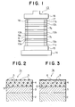
- Fig. 2 is a schematic partial vertical sectional view illustrating a first embodiment of the plated metal sheet of the present invention.
- a plated metal sheet 1 a of the first embodiment of the present invention comprises a nickel alloy plating layer 3 as a lower layer, formed on at least one surface of a metal sheet 2, and a composite metal plating layer 4 as an upper layer, in which fluorocarbon polymer particles 5 are uniformly dispersed, formed on the nickel alloy plating layer 3 as the lower layer.
- the metal sheet 2 comprises steel or an aluminum alloy.
- Grades of steel which may be used as the metal sheet 2 include, for example, machine structural carbon steel such as JIS S45C, ordinary structural steel such as JIS SS41, austenitic stainless steel such as JIS SUS201, ferritic stainless steel such as JIS SUS405, martensitic stainless steel such as JIS SUS403, and precipitation-hardened stainless steel such as JIS SUS630.
- Grades of aluminum alloy which may be used as the metal sheet 2 include, for example, aluminum alloy such as JIS 1100 and JIS 3003.
- the nickel alloy plating layer 3 as the lower layer covers at least one surface of the metal sheet 2 to prevent the production of flaws on the metal sheet 2 caused by an external force. Therefore, the nickel alloy plating layer 3 as the lower layer must have a Vickers hardness of at least 500 Hv.
- the nickel alloy plating layer 3 as the lower layer comprises, for example, a nickel-phosphorus alloy or a nickel-boron alloy.
- the nickel alloy plating layer 3 as the lower layer comprises a nickel-phosphorus alloy
- a phorphorus content in the nickel alloy plating layer 3 as the lower layer exerts an important effect on hardness of the nickel alloy plating layer 3 as the lower layer.
- a phosphorus content in the nickel alloy plating layer 3 as the lower layer of under 1 wt.% relative to the nickel alloy plating layer 3 as the lower layer, it is impossible to impart a Vickers hardness of at least 500 Hv to the nickel alloy plating layer 3 as the lower layer.
- the phosphorus content in the nickel alloy plating layer 3 as the lower layer should therefore be limited within a range of from 1 to 15 wt.% relative to the nickel alloy plating layer 3 as the lower layer.
- the nickel alloy plating layer 3 as the lower layer comprises a nickel-boron alloy
- a boron content in the nickel alloy plating layer 3 as the lower layer exerts an important effect on hardness of the nickel alloy plating layer 3 as the lower layer.
- a boron content in the nickel alloy plating layer 3 as the lower layer of under 1 wt.% relative to the nickel alloy plating layer 3 as the lower layer, it is impossible to impart a Vickers hardness of at least 500 Hv to the nickel alloy plating layer 3 as the lower layer.
- the boron content in the nickel alloy plating layer 3 as the lower layer should therefore be limited within a range of from 1 to 15 wt.% relative to the nickel alloy plating layer 3 as the lower layer.
- An average thickness of the nickel alloy plating layer 3 as the lower layer exerts an important effect on a protection of the metal sheet 2 against an external force and on a surface roughness of the nickel alloy plating layer 3 as the lower layer.
- the metal sheet 2 With an average thickness of the nickel alloy plating layer 3 as the lower layer of under 0.1 u.m, the metal sheet 2, the surface of which is covered by the nickel alloy plating layer 3 as the lower layer, tends to be easily damaged by an external force, thus making it impossible to sufficiently protect the metal sheet 2.
- an average thickness of the nickel alloy plating layer 3 as the lower layer of over 100 u.m on the other hand, the surface of the nickel alloy plating layer 3 as the lower layer is roughened, thus degrading smoothness thereof and leading to an uneconomical increment of the average thickness.
- the average thickness of the nickel alloy plating layer 3 as the lower layer should therefore be limited within a range of from 0.1 to 100 I Lm, and more preferably, within a range of from 1 to 20 ILm.
- the fluorocarbon polymer particles 5 are uniformly dispersed in the composite metal plating layer 4 as the upper layer, formed on the above-mentioned nickel alloy plating layer 3 as the lower layer.
- the fluorocarbon polymer particles 5 which are exposed on the surface of the composite metal plating layer 4 as the upper layer, permit very easy stripping of an adhesive adhering onto the surface of the composite metal plating layer 4 as the upper layer.
- the composite metal plating layer 4 as the upper layer comprises, for example, a metal selected from the group consisting of nickel, cobalt, chromium, zinc, copper and tin.
- the composite metal plating layer 4 as the upper layer may comprise an alloy of a metal selected from the above-mentioned group. Use of anyone of nickel, a nickel-phosphorus alloy or a nickel-boron alloy as the material for the composite metal plating layer 4 as the upper layer, makes it possible to impart a high hardness and an excellent corrosion resistance to the composite metal plating layer 4 as the upper layer.
- a content of the fluorocarbon polymer particles 5 in the composite metal plating layer 4 as the upper layer exerts an important effect on strippability of the plated metal sheet 1 a and on hardness of the composite metal plating layer 4 as the upper layer.
- a content of fluorocarbon polymer particles 5 in the composite metal plating layer 4 as the upper layer of under 1 vol.% relative to the composite metal plating layer 4 as the upper layer, it is impossible to impart an excellent strippability to the plated metal sheet 1 a.
- the content of the fluorocarbon polymer particles 5 in the composite metal plating layer 4 as the upper layer should be limited within a range of from 1 to 50 vol.% relative to the composite metal plating layer 4 as the upper layer.
- An average thickness of the composite metal plating layer 4 as the upper layer exerts an important effect on strippability of the plated metal sheet 1 a and on surface roughness of the composite metal plating layer 4 as the upper layer.
- an average thickness of the composite metal plating layer 4 as the upper layer of under 0.1 ⁇ m, part of the surface of the nickel alloy plating layer 3 as the lower layer is exposed without being covered by the composite metal plating layer 4 as the upper layer, resulting from the surface roughness of the nickel alloy plating layer 3 as the lower layer, and as a result, an excellent strippability cannot be imparted to the plated metal sheet 1a.
- an average thickness of the composite metal plating layer 4 as the upper layer should be limited within a range of from 0.1 to 100 ⁇ m, and more preferably, within a range of from 0.5 to 20 ⁇ m.
- An average particle size of the fluorocarbon polymer particles 5 in the composite metal plating layer 4 as the upper layer exerts an important effect on strippability of the plated metal sheet 1a.
- an average particle size of the fluorocarbon polymer particles 5 of under 0.01 ⁇ m the fluorocarbon polymer particles 5 tend to easily agglomerate in an electroplating bath when electroplating the metal sheet 2, on at least one surface of which the nickel alloy plating layer 3 as the lower layer has been formed, to form the composite metal plating layer 4 as the upper layer on the nickel alloy plating layer 3 as the lower layer.
- the fluorocarbon polymer particles 5 tend to easily settle in an electroplating bath when electroplating the metal sheet 2, on at least one surface of which the nickel alloy plating layer 3 as the lower layer has been formed, to form the composite metal plating layer 4 as the upper layer on the nickel alloy plating layer 3 as the lower layer.
- the average particle size of the fluorocarbon polymer particles 5 in the composite metal plating layer 4 as the upper layer should be limited within a range of from 0.01 to 10 Ilm, and more preferably, within a range of from 0.05 to under 0.3 ⁇ m.
- the above-mentioned plated metal sheet 1 a of the first embodiment of the present invention is manufactured as follows.
- a metal sheet 2 is electroplated or dip-plated in a known nickel alloy electroplating bath or a known nickel alloy dip-plating bath, to form, on at least one surface of the metal sheet 2, a nickel alloy plating layer 3 as a lower layer, as shown in Fig. 2.
- the metal sheet 2 having the nickel alloy plating layer 3 as the lower layer thus formed on at least one surface thereof is electroplated or dip-plated in a composite metal electroplating bath or a composite metal dip-plating bath, which contains fluorocarbon polymer particles 5 in an amount of from 1 to 100 g/t, to form on the nickel alloy plating layer 3 as the lower layer, a composite metal plating layer 4 as an upper layer, in which the fluorocarbon polymer particles 5 are uniformly dispersed, as shown in Fig. 2.
- the plated metal sheet 1 a of the first embodiment of the present invention which comprises the nickel alloy plating layer 3 as the lower layer, formed on at least one surface of the metal sheet 2, and the composite metal plating layer 4 as the upper layer, in which the fluorocarbon polymer particles 5 are uniformly dispersed, formed on the nickel alloy plating layer 3 as the lower layer.
- Fig. 3 is a schematic partial vertical sectional view illustrating a second embodiment of the plated metal sheet of the present invention.
- a plated metal sheet 1b of the second embodiment of the present invention comprises a nickel alloy plating layer 3 as a lower layer, formed on at least one surface of a metal sheet 2, and a composite metal plating layer 4 as an upper layer, in which fluorocarbon polymer particles 5 are uniformly dispersed, formed on the nickel alloy plating layer 3 as the lower layer, and the composite metal plating layer 4 as the upper layer has thereon a fluorocarbon polymer layer 6 formed by melting the fluorocarbon polymer particles 5 which are exposed on the surface of the composite metal plating layer 4 as the upper layer.
- the plated metal sheet 1b of the second embodiment of the present invention is identical with the plated metal sheet 1a of the first embodiment of the present invention except that the composite metal plating layer 4 as the upper layer has thereon the fluorocarbon polymer layer 6 formed by melting the fluorocarbon polymer particles 5 which are exposed on the surface of the composite metal plating layer 4 as the upper layer.
- the above-mentioned fluorocarbon polymer layer 6 imparts a more excellent strippability to the plated metal sheet 1 b.
- the plated metal sheet 1b of the second embodiment of the present invention is manufactured by heating the plated metal sheet 1 a of the above-mentioned first embodiment of the present invention to a prescribed temperature to melt the fluorocarbon polymer particles 5 which are exposed on the surface of the composite metal plating layer 4 as the upper layer of the plated metal sheet 1 a.
- the above-mentioned heating temperature varies with a chemical composition of the fluorocarbon polymer particles 5.
- the plated metal sheet 1 b of the second embodiment of the present invention is available by heating the plated metal sheet 1 a of the above-mentioned first embodiment of the present invention to a temperature within a range of from 300 to 400°C.
- the composite metal plating layer 4 as the upper layer of the plated metal sheet 1 b of the second embodiment of the present invention comprises a nickel-phosphorus alloy
- the above-mentioned heat treatment for melting the fluorocarbon polymer particles 5 which are exposed on the surface of the composite metal plating layer 4 as the upper layer causes uniform precipitation of Ni 3 P particles in the composite metal plating layer 4 as the upper layer, and this largely improves a Vickers hardness of the composite metal plating layer 4 as the upper layer.
- the steel sheet was subjected to a known degreasing treatment and a known pickling treatment to remove rust from the both surfaces thereof. Then, after the removal of rust, the steel sheet was electroplated under the following conditions:
- the steel sheet having the nickel-phosphorus alloy plating layer as the lower layer thus formed on each of the both surfaces thereof was electroplated under the following conditions:
- a plated metal sheet identical with the sample of the present invention No. 1 was heated at a temperature of 360 ° C for one hour to melt the fluorocarbon polymer particles which were exposed on the surface of each of the composite nickel plating layers as the upper layers to form a fluorocarbon polymer layer having an average thickness of 0.1 ⁇ m on each of the composite nickel plating layers as the upper layers, thereby preparing a sample of the present invention No. 2.
- the nickel-phosphorus alloy plating layer as the lower layer had a Vickers hardness of 1,000 Hv.
- the nickel-phosphorus alloy plating layer as the lower layer of the sample of the present invention No. 2 had a Vickers hardness of 1,000 Hv as described above, because the Ni 3 P particles were uniformly precipitated in the nickel-phosphorus alloy plating layer as the lower layer under the effect of the above-mentioned heat treatment.
- the sample of the present invention No. 2 was tested for strippability in the same manner as in the sample of the present invention No. 1.
- the epoxy resin adhering onto the surface of the sample of the present invention No. 2 was totally stripped off very easily from the surface of the sample of the present invention No. 2 without the use of a metal spatura or a knife.
- the stainless steel sheet was subjected to a known degreasing treatment and a known electrolytic pickling treatment, and furthermore, to a nickel strike plating as a pretreatment in a nickel chloride plating bath. Then, the thus pretreated stainless steel sheet was electroplated under the following conditions:
- the sample of the present invention No. 3 was tested for strippability in the same manner as in the sample of the present invention No. 1.
- most of the epoxy resin adhering onto the surface of the sample of the present invention No. 3 was very easily stripped off from the surface of the sample of the present invention No. 3 without the use of a metal spatura or a knife.
- a plated metal sheet identical with the sample of the present invention No. 3 was heated at a temperature of 360° C for one hour to melt the fluorocarbon polymer particles which were exposed on the surface of each of the composite nickel-phosphorus alloy plating layers as the upper layers to form a fluorocarbon polymer layer having an average thickness of 0.1 ⁇ m on each of the composite nickel-phosphorus alloy plating layers as the upper layers, thereby preparing a sample of the present invention No. 4.
- each of the nickel-phosphorus alloy plating layer as the lower layer and the composite nickel-phosphorus alloy plating layer as the upper layer of the sample of the present invention No. 4 had a high Vickers hardness as described above, because the NisP particles were uniformly precipitated in each of the nickel-phosphorus alloy plating layer as the lower layer and the composite nickel-phosphorus alloy plating layer as the upper layer under the effect of the above-mentioned heat treatment.
- the sample of the present invention No. 4 was tested for strippability in the same manner as in the sample of the present invention No. 1.
- the epoxy resin adhering onto the surface of the sample of the present invention No. 4 was totally stripped off very easily from the surface of the sample of the present invention No. 4 without the use of a metal spatura or a knife.
- the stainless steel sheet was subjected to a known degreasing treatment and a known electrolytic pickling treatment, and furthermore, to a nickel strike plating as a pretreatment in a nickel chloride plating bath. Then, the thus pretreated stainless steel sheet was dip-plated under the following conditions:
- the sample of the present invention No. 5 was tested for strippability in the same manner as in the sample of the present invention No. 1.
- most of the epoxy resin adhering onto the surface of the sample of the present invention No. 5 was very easily stripped off from the surface of the sample of the present invention No. 5 without the use of a metal spatura or a knife.
- a plated metal sheet identical with the sample of the present invention No. 5 was heated to a temperature of 360° C for one hour to melt the fluorocarbon polymer particles which were exposed on the surface of each of the composite nickel plating layers as the upper layers to form a fluorocarbon polymer layer having an average thickness of 0.1 IJ.m on each of the composite nickel plating layers as the upper layers, thereby preparing a sample of the present invention No. 6.
- the sample of the present invention No. 6 was tested for strippability in the same manner as in the sample of the present invention No. 1.
- the epoxy resin adhering onto the surface of the sample of the present invention No. 6 was totally stripped off very easily from the surface of the sample of the present invention No. 6 without the use of a metal spatura or a knife.
- the aluminum alloy sheet was subjected to a known degreasing treatment, a known etching treatment by the use of a caustic soda solution, and a known smut removing treatment.
- the aluminum alloy sheet was subjected to a nickel strike plating as a pretreatment in a nickel chloride plating bath. Then, the thus pretreated aluminum alloy sheet was electroplated under the following conditions:
- the sample of the present invention No. 7 was tested for strippability in the same manner as in the sample of the present invention No. 1.
- most of the epoxy resin adhering onto the surface of the sample of the present invention No. 7 was very easily stripped off from the surface of the sample of the present invention No. 7 without the use of a metal spatura or a knife.
- a plated metal sheet identical with the sample of the present invention No. 7 was heated at a temperature of 360° C for one hour to melt the fluorocarbon polymer particles which were exposed on the surface of each of the composite nickel-boron alloy plating layers as the upper layers to form a fluorocarbon polymer layer having an average thickness of 0.1 ⁇ m on each of the composite nickel-boron alloy plating layers as the upper layers, thereby preparing a sample of the present invention No. 8.
- the nickel-phosphorus alloy plating layer as the lower layer had a Vickers hardness of 1,000 Hv.
- the nickel-phosphorus alloy plating layer as the lower layer of the sample of the present invention No. 8 had a Vickers hardness of 1,000 Hv as described above, because the Ni 3 P particles were uniformly precipitated in the nickel-phosphorus alloy plating layer as the lower layer under the effect of the above-mentioned heat treatment.
- the sample of the present invention No. 8 was tested for strippability in the same manner as in the sample of the present invention No. 1.
- the epoxy resin adhering onto the surface of the sample of the present invention No. 8 was totally stripped off very easily from the surface of the sample of the present invention No. 8 without the use of a metal spatura or a knife.
- a sheet of the same steel as that in Example 1 was subjected to a known degreasing treatment and a known pickling treatment to remove rust from the both surfaces thereof. Then, after the removal of rust, the steel sheet was electroplated under the following conditions:
- the sample for comparison No. 1 was tested for strippability in the same manner as in the sample of the present invention No. 1. Since the sample for comparison No. 1 had no nickel-phosphorus alloy plating layer as a lower layer of the present invention, the sample for comparison No. 1 had the following problem: Although part of the epoxy resin still remaining on the surface of the sample for comparison No. 1 without being stripped off therefrom, was easily removed by the use of a metal spatura or a knife, flaws caused by the spatura of the knife were observed on the composite nickel plating layer as the single layer, and those flaws reached even the steel sheet.
- Example 1 A sheet of the same steel as that in Example 1 was subjected to a known degreasing treatment and a known pickling treatment to remove rust from the both surfaces thereof. Then, after the removal of rust, the steel sheet was electroplated under the same conditions as the plating conditions in Example 1 to form, on each of the both surfaces of the steel sheet, a nickel-phosphorus alloy plating layer as a lower layer identical with that in Example 1.
- the steel sheet having the nickel-phosphorus alloy plating layer as the lower layer thus formed on each of the both surfaces thereof was electroplated under the same conditions as the plating conditions in Example 1, except for a content of the fluorocarbon polymer particles of 0.5 g/i in the composite metal electroplating bath, to form, on the nickel-phosphorus alloy plating layer as the lower layer formed on each of the both surfaces of the steel sheet, a composite nickel plating layer as an upper layer, having an average thickness of 5 I lm, in which the fluorocarbon polymer particles were uniformly dispersed, thereby preparing a sample for comparison No. 2 outside the scope of the present invention.
- the sample for comparison No. 2 was tested for strippability in the same manner as in the sample of the present invention No. 1. Since the composite nickel plating layer as the upper layer of the sample for comparison No. 2 had a low content of the fluorocarbon polymer particles of 0.4 vol.% relative to the composite nickel plating layer as the upper layer, which was outside the scope of the present invention, the sample for comparison No. 2 had the following problem: It was very difficult to remove the epoxy resin adhering onto the surface of the sample for comparison No. 2 even with the use of a metal spatura or a knife.
- Example 1 A sheet of the same steel as that in Example 1 was subjected to a known degreasing treatment and a known pickling treatment to remove rust from the both surfaces thereof. Then, after the removal of rust, the steel sheet was electroplated under the same conditions as the plating conditions in Example 1 to form, on each of the both surfaces of the steel sheet, a nickel-phosphorus alloy plating layer as a lower layer identical with that in Example 1.
- the steel sheet having the nickel-phosphorus alloy plating layer as the lower layer thus formed on each of the both surfaces thereof was electroplated under the same conditions as the plating conditions in Example 1, except for a content of the fluorocarbon polymer particles of 70 g/t in the composite metal electroplating bath, to form, on the nickel-phosphorus alloy plating layer as the lower layer formed on each of the both surfaces of the steel sheet, a composite nickel plating layer as an upper layer, having an avarage thickness of 5 u.m, in which the fluorocarbon polymer particles were uniformly dispersed, thereby preparing a sample for comparison No. 3 outside the scope of the present invention.
- Example 2 A sheet of the same steel as that in Example 1 was subjected to a known degreasing treatment and a mown pickling treatment to remove rust from the both surfaces thereof. Then, after the removal of rust, the >teel sheet was electroplated under the following conditions:
- the steel sheet having the nickel-phosphorus alloy plating layer as the lower layer thus formed on each of the both surfaces thereof was electroplated under the same conditions as the palting conditions in Example 1 to form, on the nickel-phosphorus alloy plating layer as the lower layer formed on each of the both surfaces of the steel sheet, a composite nickel plating layer as an upper layer, identical with that in Example 1, having an average thickness of 5 ⁇ m, in which the fluorocarbon polymer particles were uniformly dispersed, thereby preparing a sample for comparison No. 4 outside the scope of the present invention.
- the sample for comparison No. 4 was tested for strippability in the same manner as in the sample of the present invention No. 1.
- the sample for comparison No. 4 had the following problem: Most of the epoxy resin adhering onto the surface of the sample for comparison No. 4 was very easily stripped off therefrom without the use of a metal spatura or a knife. Part of the epoxy resin still remaining onto the surface of the sample for comparison No. 4 without being stripped off therefrom, was easily removed by the use of a metal spatura or a knife. However, there were observed flaws caused by the use of the spatura of the knife on the composite nickel plating layer as the upper layer and the nickel-phosphorus alloy plating layer as the lower layer, and those flaws reached even the steel sheet.
- a sheet of the same steel as that in Example 1 was subjected to a known degreasing treatment and a known pickling treatment to remove rust from the both surfaces thereof. Then, after the removal of rust, the steel sheet was electroplated under the following conditions;
- the steel sheet having the nickel-phosphorus alloy plating layer as the lower layer thus formed on each of the both surfaces thereof was electroplated under the same conditions as the plating conditions in Example 1 to form, on the nickel-phosphorus alloy plating layer as the lower layer formed on each of the both surfaces of the steel sheet, a composite nickel plating layer as an upper layer, identical with that in Example 1, having an average thickness of 5 u.m, in which the fluorocarbon polymer particles were uniformly dispersed, thereby preparing a sample for comparison No. 5 outside the scope of the present invention.
- the sample for comparison No. 5 Since the nickel-phosphorus alloy plating layer as the lower layer of the sample for comparison No. 5 had cracks as described above, the sample for comparison No. 5 was unsuitable as a separating sheet to be used when manufacturing a printed circuit board by the use of a hot press.
- a sheet of the same stainless steel as that in Example 5 was subjected to a known degreasing treatment and a known electrolytic pickling treatment, and furthermore, to a nickel strike plating as a pretreatment in a nickel chloride plating bath. Then, the thus pretreated stainless steel sheet was dip-plated under the following conditions:
- the stainless steel sheet having the nickel-boron alloy plating layer as the lower layer thus formed on each of the both surfaces thereof was electroplated under the same conditions as the plating conditions in Example 5 to form, on the nickel-boron alloy plating layer as the lower layer formed on each of the both surfaces of the stainless steel sheet, a composite nickel plating layer as an upper layer identical with that in Example 5, having an average thickness of 5 u.m, in which the fluorocarbon polymer particles were uniformly dispersed, thereby preparing a sample for comparison No. 6 outside the scope of the present invention.
- the sample for comparison No. 6 was tested for strippability in the same manner as in the sample of the present invention No. 1.
- the sample for comparison No. 6 had the following problem: Most of the epoxy resin adhering onto the surface of the sample for comparison No. 6 was very easily stripped off therefrom without the use of a metal spatura or a knife. Part of the epoxy resin still adhering onto the surface of the sample for comparison No. 6 without being stripped off therefrom, was easily removed by the use of a metal spatura or a knife. However, there were observed flaws caused by the use of the spatura or the knife on the composite nickel plating layer as the upper layer and the nickel-boron alloy plating layer as the lower layer, and those flaws reached even the stainless steel.
- a sheet of the same stainless steel as that in Example 5 was subjected to a known degreasing treatment and a known electrolytic pickling treatment, and furthermore, to a nickel strike plating as a pretreatment in a nickel chloride plating bath. Then, the thus pretreated stainless steel sheet was dip-plated under the following conditions:
- the stainless steel sheet having the nickel-boron alloy plating layer as the lower layer thus formed on each of the both surfaces thereof was electroplated under the same conditions as the plating conditions in Example 5 to form, on the nickel-boron alloy plating layer as the lower layer formed on each of the both surfaces of the stainless steel sheet, a composite nickel plating layer as an upper layer, identical with that in Example 5, having an average thickness of 5 am, in which the fluorocarbon polymer particles were uniformly dispersed, thereby preparing a sample for comparison No. 7 outside the scope of the present invention.
- the sample for comparison No. 7 Since the nickel-boron alloy plating layer as the lower layer of the sample for comparison No. 7 had cracks as described above, the sample for comparison No. 7 was unsuitable as a separating sheet to be used when manufacturing a printed circuit board by the use of a hot press.
- a plated metal sheet provided with a plurality of plating layers excellent in strippability and having a high hardness, which is most suitable as a separating sheet to be used when manufacturing a printed circuit board by the use of a hot press, thus providing many industrially useful effects.
Landscapes
- Chemical & Material Sciences (AREA)
- Engineering & Computer Science (AREA)
- Chemical Kinetics & Catalysis (AREA)
- Electrochemistry (AREA)
- Materials Engineering (AREA)
- Metallurgy (AREA)
- Organic Chemistry (AREA)
- Manufacturing & Machinery (AREA)
- Microelectronics & Electronic Packaging (AREA)
- Mechanical Engineering (AREA)
- Laminated Bodies (AREA)
- Electroplating Methods And Accessories (AREA)
- Moulds For Moulding Plastics Or The Like (AREA)
Applications Claiming Priority (2)
| Application Number | Priority Date | Filing Date | Title |
|---|---|---|---|
| JP111479/90 | 1990-04-26 | ||
| JP2111479A JPH049499A (ja) | 1990-04-26 | 1990-04-26 | 優れた剥離性および高い硬度を有するめつき金属板 |
Publications (1)
| Publication Number | Publication Date |
|---|---|
| EP0453633A1 true EP0453633A1 (de) | 1991-10-30 |
Family
ID=14562299
Family Applications (1)
| Application Number | Title | Priority Date | Filing Date |
|---|---|---|---|
| EP90121511A Withdrawn EP0453633A1 (de) | 1990-04-26 | 1990-11-09 | Plattiertes Stahlblech mit einer Vielzahl von Plattierungsschichten ausgezeichneter Lösbarkeit und hoher Härte |
Country Status (4)
| Country | Link |
|---|---|
| US (1) | US5100739A (de) |
| EP (1) | EP0453633A1 (de) |
| JP (1) | JPH049499A (de) |
| CA (1) | CA2028951C (de) |
Cited By (1)
| Publication number | Priority date | Publication date | Assignee | Title |
|---|---|---|---|---|
| EP1854909A2 (de) | 2006-05-12 | 2007-11-14 | Denso Corporation | Beschichtungsstruktur und Verfahren zur Herstellung derselben |
Families Citing this family (7)
| Publication number | Priority date | Publication date | Assignee | Title |
|---|---|---|---|---|
| JPH11217699A (ja) * | 1998-01-30 | 1999-08-10 | Noge Denki Kogyo:Kk | メッキ形成体 |
| JP3515091B2 (ja) * | 2001-10-30 | 2004-04-05 | 株式会社共立 | 内燃エンジン用シリンダ |
| WO2004009248A1 (ja) * | 2002-07-18 | 2004-01-29 | Dai Nippon Printing Co., Ltd. | 塗工用ダイヘッド、塗工装置、塗工用ダイヘッドの製造方法 |
| US20050221112A1 (en) * | 2004-03-31 | 2005-10-06 | Daewoong Suh | Microtools for package substrate patterning |
| KR100717909B1 (ko) * | 2006-02-24 | 2007-05-14 | 삼성전기주식회사 | 니켈층을 포함하는 기판 및 이의 제조방법 |
| WO2020137874A1 (ja) | 2018-12-27 | 2020-07-02 | 日本製鉄株式会社 | 加工後耐食性に優れたNiめっき鋼板、及びNiめっき鋼板の製造方法 |
| DE102022125373B4 (de) * | 2022-09-30 | 2024-09-19 | Hueck Rheinische Gmbh | Presswerkzeug mit einer Nickelschicht |
Citations (2)
| Publication number | Priority date | Publication date | Assignee | Title |
|---|---|---|---|---|
| DE3333121A1 (de) * | 1983-09-14 | 1985-03-28 | AHC-Oberflächentechnik, Friebe & Reininghaus GmbH & Co KG, 5014 Kerpen | Dispersionsschichten |
| WO1990002220A1 (fr) * | 1988-08-25 | 1990-03-08 | Werner Flühmann Ag | Composition de couche anti-usure a bas coefficient de frottement et article manufacture comportant cette couche |
Family Cites Families (14)
| Publication number | Priority date | Publication date | Assignee | Title |
|---|---|---|---|---|
| US3421972A (en) * | 1965-06-28 | 1969-01-14 | Koppers Co Inc | Process for directly bonding polytetrafluoroethylene to metal,adhesive composition used therefor and laminated product thereof |
| US3716348A (en) * | 1970-06-01 | 1973-02-13 | G Perkins | Method of forming abrasion-resistant self-lubricating coating on ferrous metals and aluminum and resulting articles |
| JPS4920459B1 (de) * | 1970-12-26 | 1974-05-24 | ||
| US4222828A (en) * | 1978-06-06 | 1980-09-16 | Akzo N.V. | Process for electro-codepositing inorganic particles and a metal on a surface |
| JPS6053522B2 (ja) * | 1978-07-05 | 1985-11-26 | 三菱電機株式会社 | 開閉機器の故障位置検知装置 |
| JPS5831292B2 (ja) * | 1978-09-20 | 1983-07-05 | 株式会社日立製作所 | 熱硬化性樹脂成形金型 |
| JPS5831292A (ja) * | 1981-08-19 | 1983-02-23 | Kanagawaken | ドレンの熱回収方法 |
| JPS6010816A (ja) * | 1983-06-27 | 1985-01-21 | インタ−ナショナル ビジネス マシ−ンズ コ−ポレ−ション | 差動論理回路 |
| JPS60197880A (ja) * | 1984-03-19 | 1985-10-07 | Aisin Seiki Co Ltd | 複合メッキ被膜 |
| DE3545826A1 (de) * | 1984-12-24 | 1986-06-26 | Kabushiki Kaisha Riken, Tokio/Tokyo | Kolbenring |
| JPS61179899A (ja) * | 1985-02-04 | 1986-08-12 | Teikoku Piston Ring Co Ltd | 耐摩耗性に優れた複合ニツケル−燐合金めつき |
| CH667108A5 (de) * | 1985-04-22 | 1988-09-15 | Fluehmann Ag Werner | Galvanisches bad zum gemeinsamen abscheiden von metall und einem dauerschmierenden feststoffschmiermittel. |
| US4830889A (en) * | 1987-09-21 | 1989-05-16 | Wear-Cote International, Inc. | Co-deposition of fluorinated carbon with electroless nickel |
| JPH049498A (ja) * | 1990-04-26 | 1992-01-14 | Nkk Corp | 優れた剥離性および高い硬度を有するニツケル‐燐合金めつき金属板およびその製造方法 |
-
1990
- 1990-04-26 JP JP2111479A patent/JPH049499A/ja active Pending
- 1990-10-29 US US07/605,261 patent/US5100739A/en not_active Expired - Fee Related
- 1990-10-30 CA CA002028951A patent/CA2028951C/en not_active Expired - Fee Related
- 1990-11-09 EP EP90121511A patent/EP0453633A1/de not_active Withdrawn
Patent Citations (2)
| Publication number | Priority date | Publication date | Assignee | Title |
|---|---|---|---|---|
| DE3333121A1 (de) * | 1983-09-14 | 1985-03-28 | AHC-Oberflächentechnik, Friebe & Reininghaus GmbH & Co KG, 5014 Kerpen | Dispersionsschichten |
| WO1990002220A1 (fr) * | 1988-08-25 | 1990-03-08 | Werner Flühmann Ag | Composition de couche anti-usure a bas coefficient de frottement et article manufacture comportant cette couche |
Non-Patent Citations (1)
| Title |
|---|
| DERWENT WPIL, accession no. 82-64872E [31], Derwent Publications Ltd, London, GB; & JP-A-57 103 107 (MATSUSHITA) * |
Cited By (2)
| Publication number | Priority date | Publication date | Assignee | Title |
|---|---|---|---|---|
| EP1854909A2 (de) | 2006-05-12 | 2007-11-14 | Denso Corporation | Beschichtungsstruktur und Verfahren zur Herstellung derselben |
| EP1854909A3 (de) * | 2006-05-12 | 2007-12-26 | Denso Corporation | Beschichtungsstruktur und Verfahren zur Herstellung derselben |
Also Published As
| Publication number | Publication date |
|---|---|
| US5100739A (en) | 1992-03-31 |
| CA2028951A1 (en) | 1991-10-27 |
| CA2028951C (en) | 1993-11-16 |
| JPH049499A (ja) | 1992-01-14 |
Similar Documents
| Publication | Publication Date | Title |
|---|---|---|
| US6652962B1 (en) | Resin-coated composite foil, production and use thereof | |
| US6183880B1 (en) | Composite foil of aluminum and copper | |
| EP0930811B1 (de) | Kupfer-Verbundfolie, Verfahren zu deren Herstellung, und kupferkaschiertes Laminat und Leiterplatte unter Verwendung derselben | |
| US4357395A (en) | Transfer lamination of vapor deposited foils, method and product | |
| US5024900A (en) | Composite nickel-phosphorus alloy plated metal sheet excellent in strippability and having high hardness and method for manufacturing same | |
| EP0996319B1 (de) | Verbundmaterial zur Verwendung in der Herstellung von gedruckten Leiterplatten | |
| KR20020042671A (ko) | 동크래드 적층판의 제조방법 | |
| KR100595381B1 (ko) | 복합동박 및 그 제조방법 및 해당 복합동박을 이용한 동피복적층판 및 프린트배선판 | |
| EP0453633A1 (de) | Plattiertes Stahlblech mit einer Vielzahl von Plattierungsschichten ausgezeichneter Lösbarkeit und hoher Härte | |
| GB1583544A (en) | Metal-clad laminates | |
| US5447619A (en) | Copper foil for the manufacture of printed circuit boards and method of producing the same | |
| JP3392066B2 (ja) | 複合銅箔およびその製造方法並びに該複合銅箔を用いた銅張り積層板およびプリント配線板 | |
| GB2091634A (en) | Transfer lamination of vapour deposited copper thin sheets and films | |
| US6238778B1 (en) | Component of printed circuit boards | |
| US6329077B1 (en) | Plate-shaped compression mold, process for producing the same and process for making laminate therewith | |
| EP1089603A2 (de) | Behandlung von Kupferfolie mit verbesserter Bindungsfestigkeit und Unterätzung | |
| CN1099334C (zh) | 印刷电路板的组件 | |
| EP0700238B1 (de) | Kupferfolie zur Herstellung einer Leiterplatte | |
| JP4096171B2 (ja) | プリント配線板用銅箔複合板およびプリント配線板の製造方法 | |
| US6060666A (en) | Electrolytic layer applied to metallic foil to promote adhesion to a polymeric substrate | |
| DE2702283A1 (de) | Uebertragungsmaterial fuer rauhe oberflaechen, verfahren zu seiner herstellung und seine verwendung | |
| JPS58199151A (ja) | 化学メツキ用積層板の製造方法 | |
| JPH07235744A (ja) | 印刷回路用高高温伸び銅箔及びその製造方法 | |
| JP2000315848A (ja) | 銅張り積層板の製造方法およびプリント配線板 | |
| GB2185757A (en) | Dendritic surface treatment of metal layers |
Legal Events
| Date | Code | Title | Description |
|---|---|---|---|
| PUAI | Public reference made under article 153(3) epc to a published international application that has entered the european phase |
Free format text: ORIGINAL CODE: 0009012 |
|
| 17P | Request for examination filed |
Effective date: 19901206 |
|
| AK | Designated contracting states |
Kind code of ref document: A1 Designated state(s): DE FR GB |
|
| 17Q | First examination report despatched |
Effective date: 19930204 |
|
| STAA | Information on the status of an ep patent application or granted ep patent |
Free format text: STATUS: THE APPLICATION IS DEEMED TO BE WITHDRAWN |
|
| 18D | Application deemed to be withdrawn |
Effective date: 19940428 |