EP0465762B1 - Classeur pour articles comprenant une presse. - Google Patents
Classeur pour articles comprenant une presse. Download PDFInfo
- Publication number
- EP0465762B1 EP0465762B1 EP91103005A EP91103005A EP0465762B1 EP 0465762 B1 EP0465762 B1 EP 0465762B1 EP 91103005 A EP91103005 A EP 91103005A EP 91103005 A EP91103005 A EP 91103005A EP 0465762 B1 EP0465762 B1 EP 0465762B1
- Authority
- EP
- European Patent Office
- Prior art keywords
- tray
- sheets
- trays
- sorter
- moving member
- Prior art date
- Legal status (The legal status is an assumption and is not a legal conclusion. Google has not performed a legal analysis and makes no representation as to the accuracy of the status listed.)
- Expired - Lifetime
Links
Images












Classifications
-
- B—PERFORMING OPERATIONS; TRANSPORTING
- B65—CONVEYING; PACKING; STORING; HANDLING THIN OR FILAMENTARY MATERIAL
- B65H—HANDLING THIN OR FILAMENTARY MATERIAL, e.g. SHEETS, WEBS, CABLES
- B65H39/00—Associating, collating, or gathering articles or webs
- B65H39/10—Associating articles from a single source, to form, e.g. a writing-pad
- B65H39/11—Associating articles from a single source, to form, e.g. a writing-pad in superposed carriers
-
- B—PERFORMING OPERATIONS; TRANSPORTING
- B65—CONVEYING; PACKING; STORING; HANDLING THIN OR FILAMENTARY MATERIAL
- B65H—HANDLING THIN OR FILAMENTARY MATERIAL, e.g. SHEETS, WEBS, CABLES
- B65H2408/00—Specific machines
- B65H2408/10—Specific machines for handling sheet(s)
- B65H2408/11—Sorters or machines for sorting articles
- B65H2408/113—Sorters or machines for sorting articles with variable location in space of the bins relative to a stationary in-feed path
Definitions
- the present invention relates to a sorter with a sheet pressing means.
- the sheet pressing means presses sheets to be stapled against a tray, not to move from a position during transportation of the tray to a predetermined stapling position.
- JP-A-1-231757 discloses that after a bin is moved vertically from a sheet discharge position to an operation position where the bin does not move anymore, a solenoid is energized so that a curl retainer retains the curls of sheets and simultaneously a pulse motor is rotated so that a conforming rod is moved to conform the sheets with a reference plate. At the time of the end of conformation by the conforming rod, the curl retainer is halfway retaining the curls of sheets. After that, when a defined time is elapsed, the curl retainer completely retains the sheets. Then, when a further defined time is elapsed, a motor is energized, so that a stapler is rotated from a retracted position to an operation position. At this time the sheets, stacked on the bin, are guided between the head of the stapler and an anvil by means of upper and lower guides.
- JP-A-1-43456 discloses the upper and lower guides, as discussed above, as an embodiment and also a retaining rod, which is rotated by a motor through gears as another embodiment.
- such a sorter with a stapler performs positioning of the stapler to sheets on each tray by merely moving the stapler to the tray. Also in sorters with operation devices for applying various operations, such as bonding, to sheets on trays, the operation devices are moved toward the trays and then positioned.
- the conventional article pressing device requires a combination of actuators, and is disadvantageous in that the construction thereof becomes complicated and large sized. For this reason, the article pressing device cannot be incorporated into small apparatuses such as a sorter in which each of trays with sheets is transported to an operation position, for example, a stapling position for stapling.
- the conventional sorter is liable to cause sheets on trays to be slipped or lifted by contacting the sheet operation device such as a stapler when the operation device is moved toward the tray and positioned.
- the stapler performs the operation on the sheets out of the stacked alignment.
- a sorter which comprises: a plurality of trays for receiving and stacking sheets thereon, the sheets being discharged from a predetermined sheet discharge position; means for stapling the sheets on the trays at an operation position; means for sequentially moving the trays between the sheet discharge position and the operation position; and which is characterized by sheet pressing means for downwardly pressing the sheets against the corresponding trays in a manner linked with the movement of the trays toward the operation position.
- the sheet pressing means may comprise: a base arranged in the vicinity of the operation position to which the tray carrying sheets is sequentially transported in an tray transporting direction; a first moving member arranged on the base for reciprocal movement in the tray transporting direction; a second moving member arranged on the first moving member for reciprocal movement in the tray transporting direction, the second moving member being adapted to contact each tray transported to the operation position; first biasing means for biasing the first moving member in a direction opposite to the tray transporting direction; second biasing means for biasing the second moving member in a direction opposite to the tray transporting direction by a biasing force smaller than a biasing force of the first biasing means; pressing arm rotatably mounted on the first moving member for movement toward and away from the sheets in each tray at the operation position; and link means arranged between the pressing arm and the second moving member for moving the pressing arm when the first and second moving members are relatively moved.
- the link means may comprise a first link and a second link, each of the first and second links being pivotally supported on the first moving member through a supporting pin;
- the pressing arm may have a proximal end and a distal end;
- the first link may be connected at one end to the proximal end of the pressing arm and at the other end to one end of the second link;
- the second link may be connected at the other end to the second moving member.
- the second biasing means may comprise a spring extended between the first link and the first moving member.
- the pressing arm may comprise a pressing roller rotatably mounted on the distal end of the pressing arm.
- Each of the trays may comprise means for defining a cutout; and the treating means may comprise a stapler for stapling the sheets at the cutout of each tray.
- a sorter may further comprise sensing means, located in the vicinity of the operation position, for detecting a sheet placed at the cutout to produce a detection signal, whereby the stapler is controlled in response to the detection signal.
- a sorter of the present invention will be described with reference to Figs. 1 to 25.
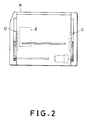
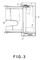
- the sorter deals with sheets as articles to be treated and is provided with a stapler. Before describing the construction of the sorter in detail, it will be generally described with reference to Figs. 1 to 3.
- the reference character A designates casing body, and B a tray unit including a plurality of trays projecting from the casing body A .
- Each tray of the tray section B is arranged to be vertically movable.
- Reference character C and D each indicates a Geneva wheel mechanism which includes a pair of Geneva wheels. The Geneva wheel mechanisms sequentially shift the plurality of trays and hold the trays in an open state in which the tray is capable of receiving a sheet.
- the reference character E designates a stapler provided within the casing body A .
- reference numeral 10 designates a main frame accommodated in the casing body A .
- the main frame 10 includes a right side frame 10A and a left side frame 10B which are vertically erected in parallel with the opposite sides of the casing body A .
- Each of the side frames 10A and 10B is provided with first slots 10C and 10D for guiding trays, respectively.
- the side frames 10A and 10B are further provided with second slots 10E and 10F for guiding tray carriers, respectively.
- the tray carriers will be described hereinafter.
- the first slots 10C and 10D have vertical opposite end portions and arcuate portions 10C1, 10C2 and 10D1, 10D2 formed to be continuous to the vertical opposite end portions, respectively (Fig. 4 and Figs. 21(a) to 21(E)).
- the arcuate portions 10C1, 10C2 and 10D1, 10D2 are formed to correspond to radius of Geneva wheels which will be described hereinafter.
- the second slots 10E and 10F extend vertically.
- the tray section B includes a plurality of trays 12 l to 12 n vertically arranged in a tray carrier 15. As shown in Fig. 8, each of the trays 12 l to 12 n is integrally provided with a right side wall 12B extending upwardly at the right angle with a bottom wall 12A on the right side, a rear side wall 12D extending upwardly at the right angle with the bottom wall 12A on the rear side and a left side wall 12C extending downwardly at the right angle with the bottom wall 12A on the left side, the left side wall 12C having a height larger than the right side wall 12B.
- the tray By providing the upward side wall 12B and the downward side wall 12C to each of the trays 12 l -12 n , the tray is increased in vertical section modulus, thereby being enhanced in strength.
- the trays 12 l -12 n may be thus reduced in thickness.
- Each of the trays 121-12 n is provided at the rear right corner thereof with a cutout 12E for stapling operation for sheets which will be described hereinafter.
- Each tray is further provided at a front portion thereof with a cutout 12F for facilitating taking out sheets.
- each tray On the rear right side of the bottom wall 12A and the rear side of the left side wall 12C are respectively provided with horizontal rear tray pins 12G and 12H, which are vertically movably fitted into corresponding through slots 10C and 10D.
- Front tray pins 12J and 12K are provided on the front right side of the bottom wall 12A and the front side of a horizontal wall 12I which extends from the lower edge of the left side wall 12C of each tray, respectively, to horizontally project.
- the front tray pins 12J and 12K are slidably engaged with corresponding front guide members 14, which will be described later.
- Reference characters 12L and 12M designate safety plates which respectively extend from the right side wall 12B and left side wall 12C horizontally outwardly so that an operator may not put his fingers or hand between stacked trays 12 l -12 n carelessly.
- the trays 121-12n are held within a tray carrier 15, shown in Fig. 8, in a stacked fashion.
- the tray carrier 15 has a pair of substantially L-shaped carrier side frames 16 and 18 interconnected with stays 19 so that the carrier side frames 16 and 18 are horizontally spaced.
- the carrier side frames 16 and 18 are respectively provided at rear portions thereof with a pair of vertically arranged guide pins 16A, 16B and guide pins 18A, 18B, which are vertically slidably guided in respective second slots 10E and 10F of the casing body A .
- the carrier side frames 16 and 18 are respectively provided at the front end thereof with front guide members 14 and 14 so that the front guide members 14 and 14 are symmetrical about the center line of the tray carrier 15.
- the front guide members 14 and 14 have substantially V-shaped guide grooves 14A1-14A n formed in oppositing surfaces thereof in a number corresponding to the number of the trays 121-12 n although the guide grooves 14A1-14A n of the right side guide member 14 are not shown in Fig. 8.
- the front tray pin 12J and 12K of each of the trays 121-12 n are slidably fitted into corresponding guide grooves 14A1-14A n .
- the carrier side frames 16 and 18 have vertical poles 16Z and 18Z integrally formed with rear ends thereof, respectively.
- the vertical poles 16Z and 18Z are provided at respective upper end portions thereof with pivotal first links 16C and 18C, to which pivotably connected are second links 16E and 18E having dummy pins 16D and 18D, respectively.
- the dummy pins 16D and 18D are vertically slidably fitted into respective first slots 10C and 10D of the main frame 10 as well as the rear tray pins 12G and 12H so that the dummy pins 16D and 18D are located above the rear tray pins 12G and 12H.
- An upper safety cover 15A is extended between the first links 16C and 18C whilst a lower safety cover 15B between the second links 16E and 18E.
- the upper safety cover 15A and the lower safety cover 15B prevent a hand of an operator from being placed in the devices.
- Resist pins 16F and 18F are provided to upper ends of the vertical poles 16Z and 18Z to be adjustable in vertical position, respectively.
- the resist pins 16F and 18F are mounted to the vertical poles 16Z and 18Z so that they are vertically movably fitted into the first slots 10C and 10D of the main frame 10 and may be urged against the dummy pins 16D and 18D, respectively.
- the rear tray pins 12G and 12H of the trays 12 l -12 n and the dummy pins 16D and 18D are inserted into respective first slots 10C and 10D in such a fashion as to be strongly tightly held between the rear ends 16G and 18G and the resist pins 16F and 18F of the side frames 16 and 18, respectively.
- a sheet transporting mechanism which transports a sheet, discharged from a copying machine or the like, onto the trays 121-12 n .
- 20 indicates a transporting guide which is composed of a pair of guide plates 20A and 20B mounted to a main frame 10 to arrange the guide plate 20A above the guide plate 20B.
- the transporting guide 20 is arranged so that an entrance portion thereof is positioned at a sheet discharge opening of a copying machine not shown.
- the transporting guide 20 is provided at an outlet portion thereof with a sheet putting aside mechanism shown in Fig. 11.
- the sheet putting aside mechanism has an upper guide plate 80A having a plurality of pinch rollers 82 mounted on it.
- the sheet putting aside mechanism is further provided with a lower guide plate 80B.
- the mechanism brings a sheet S (S1 or S2) downward in Fig. 12 while transporting the sheets S between the pinch rollers 82 and feed rollers 84 located on the side of the lower guide plate 80B.
- the sheet S1 is a A4 size sheet arranged along the transporting direction shown by the arrows while the sheet S2 a A4 size sheet arranged crosswise.
- the pinch rollers 82 are rotatably mounted to the upper guide plate 80A through corresponding leaf springs 86.
- Each of the feed rollers 84 is mounted to a corresponding one of two roller shafts 90 through a pivot roller 88.
- the roller shafts 90 are rotatably supported on a right side plate 92A and a left side plate 92B of a case 92.
- the pivot roller 88 is a spherical joint constituting a constant velocity joint which enables to transmit the rotation of the roller shaft 90 to the corresponding feed roller 84, and which makes the axial direction of each feed roller 84 variable.
- the case 92 includes an upper plate 92C, which has first links 96A and 96B angularly movably supported at opposite ends thereof by means of vertical pins 94A and 94B, respectively.
- the first links 96A and 96B are spring biased at intermediate portions thereof by springs 98A and 98B not to move upwardly, respectively.
- the opposite free ends of each of the first links 96A, 96B are connected to corresponding second links 100A and 100B.
- the second links 100A and 100B engage with corresponding resilient arms 102A which are mounted on roller guides 102 provided to correspond in number to the feed rollers 84.
- Each roller guide 102 is rotatably supported at a supporting shaft 102B thereof on the upper plate 92C of the case 92, and is angularly moved in accordance with lateral movement of the corresponding second link 100A, 100B which movement is transmitted through the corresponding arm 102A.
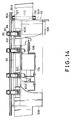
- Each roller guide 102 is provided with a roller restrainer 102C substantially in the shape of U as viewed in Fig. 14. The roller restrainers 102C surround the opposite surfaces of corresponding feed rollers 84 not to prevent rotation thereof.
- Each roller guide 102 changes the direction of the corresponding feed roller 84 according to the rotational angle thereof.
- the roller guides 102 each has a guide arm 102D horizontally projecting from them.
- Each guide arm 102D is provided at a distal end thereof with a guide pin 102E, which is guided in a corresponding guide groove 92D formed through the upper plate 92C of the case 92.
- the corresponding roller guide 102 is restricted in rotational angle range.
- each of the roller guides 102 are limited in rotational angle range so that the corresponding feed roller 84 is allowed to angularly move 15° between the position, indicated by the solid line, and the position by the dot-and-dash line in Fig. 12.
- the second link 100A is connected to an solenoid 104 through a slide arm 100C, which downwardly passes through the upper plate 92C of the case 92.
- the second link 100A is also connected to a return spring 106.
- the second link 100A is moved by the actuation of the solenoid 104 in one lateral direction shown by arrow L in Fig. 13 and by the restoring force of a spring 106 in the direction opposite to arrow L.
- Each of the roller shafts 90 has a driven pulley 107 mounted on a right hand end thereof.
- a timing belt 112 is extended around the driven pulleys 107 and a drive pulley 110 of a transporting motor 108 which is mounted on the side plate 92A of the case 92.
- the two roller shafts 90 are thus rotated in a direction to transport sheets in the sheet transporting direction shown by arrows in Fig. 12.
- a first passage sensor 114 which detects a central portion of each sheet S1 or S2.
- the first passage sensor 114 is a limit switch of which lever 114A is depressed by a sheet S1 or S2 for actuation, the lever 114A being located between the upper guide plate 80A and the lower guide plate 80B as shown in Fig. 15.
- the first passage sensor 114 is omitted for illustration purpose.
- a second passage sensor 116 is provided at the right edge of the lower guide plate 80B so as to detect passage of a right hand edge of each sheet S1 or S2.
- the second passage sensor 116 is a photosensor.
- Geneva wheel assemblies 40 and 42 are provided on the outside portions of the side frames 10A and 10B, respectively.
- the Geneva wheel assemblies 40 and 42 are identical to each other but are mirror symmetrically arranged, and only the right side Geneva wheel assembly 40 will be described.
- the Geneva wheel assembly 40 includes a pair of Geneva wheels 401 and 402 as shown in Fig. 4.
- the Geneva wheel 401 is equal in diameter to the Geneva wheel 402 and is arranged above the Geneva wheel 402.
- the Geneva wheels 401 and 402 are provided with grooves 40C1 and 40C2 to engage with a rear tray pin 12G, respectively.
- the Geneva wheels 401 and 402 are secured to shafts 40A1 and 40A2 rotatably supported on the right side frame 10A, respectively.
- Gears 40B1 and 40B2 which are equal in diameter to each other are also mounted on the shafts 40A1 and 40A2 and rotate together with the Geneva wheels 401 and 402, respectively.
- the Gears 40B1 and 40B2 engage a gear 40B3.
- the shafts 40A1 and 40A2 are aligned in parallel with vertical portions 10C4 and 10C5 of the first slot 10C.
- the Geneva wheels 401 and 402 are arranged so that the grooves 40C1 and 40C2 are rotated with a predetermined difference in phase from each other.
- a timing belt 47 extends between a driven pulley 41 and a transmission pulley 46.
- the driven pulley 41 is mounted on the lower shaft 40A2, and the transmission pulley 46 is secured to a shaft 44 which is rotatably supported on the side frames 10A and 10B.
- a transmission pulley 48 is mounted on the shaft 44, and meshes with a drive gear 52 which is secured to the output shaft of an electric motor 50 mounted on the left side frame 10B.
- the shaft 44 has another transmission pulley 46 secured at the other end thereof, and this transmission pulley 46 is connected to another driven pulley 41 through another timing belt 47.
- This driven pulley 41 is mounted on a shaft on which the Geneva wheel 422 is mounted.
- the Geneva wheels 401, 402 and 421, 422 are, as described hereinafter, arranged so that grooves 40C1, 40C2 and 42C1, 42C2 are engageable with rear tray pins 12G and 12H, respectively.
- the Geneva wheels 401 and 421 are equal in height of the mounted positions thereof, and Geneva wheels 402 and 422 equal in height of the mounted position thereof.
- the rear tray pin 12G of each tray 121-12 n is provided at the same height as the bottom wall 12A thereof whereas the rear tray pin 12H thereof at the height of the lower edge of the left side wall 12C. Consequently, each tray 121-12 n is held in such a fashion that the bottom wall 12A thereof is inclined rearwardly as well as rightwardly; the tray is thus held with the cutout 12E placed lowermost.
- the right and left transmission pulleys 46 are rotated in the same direction by energizing the motor 50, so that two pairs of Geneva wheels 401 and 421; 402 and 422 are rotated.
- this causes the rear tray pins 12G and 12H of one tray to engage with grooves 40C and 42C of Geneva wheel assemblies 40 and 42, respectively.
- the rear tray pins 12G and 12H of the tray are thus elevated along the arcuate portions 10C1, 10C2 of the first slot 10C and arcuate portions 10D1, 10D2 of the first slot 10D, respectively. This rearwardly enlarges the gap between the tray and an adjacent lower tray thereof.
- a cam 54 is mounted on the upper right shaft 40A1 at a position determined in connection with the groove 40C1, and a position detection switch 56 is provided to the right side frame 10A at a position corresponding to the position of cam 54 for detecting the stop position of the upper Geneva wheel 401.
- the position detection switch 56 is switched when the cam 54 is brought into contact with an activating lever 56A thereof.
- a lower limit detection switch 58 is mounted to the right side frame 10A adjacent to the lower end of the first slot 10C.
- the lower limit detection switch 58 is switched by bringing a lowermost rear tray pin 12G into contact with the actuating lever 58A when the dummy pins 16D and 18D are respectively placed within the grooves 40C1 and 42C1 of the upper Geneva wheels 401 and 421, and when the position detection switch 56 detects the stop position of the cam 54.
- the tray drawing out mechanism is constituted by combining the first slots 10C and 10D and the pair of the Geneva wheel assemblies 40 and 42 which are mirror symmetrically arranged to the side frames 10A and 10B. Only the right side portion of the tray drawing out mechanism will be hence described.
- the first slot 10C is continuously formed in the right side frame 10A so that it has opposite vertical portions 10C4 and 10C5 and symmetrical arcuate portions 10C1 and 10C2 communicated to the vertical portions 10C4 and 10C5, respectively.
- the arcuate portions 10C1 and 10C2 are formed to overlap quarters of the circular loci of the groove 40C1 of the Geneva wheel 401 and the groove 40C2 of the Geneva wheel 421, respectively.
- the arcuate portions 10C1 and 10C2 communicate to each other at an extended portion 10C3 which extends in a direction of a common tangent of the Geneva wheels 401 and 402. While being shifted, each tray is, as shown in Fig. 21(E), pulled out rearwardly by about 3/4 of the diameter of the Geneva wheels 401 and 402 by the guiding of the first slot 10C.
- a return spring 10G is provided to the right side frame 10A so that an upper end portion thereof is located at the inner end portion of the extended portion 10C3.
- the upper end portion of the return spring 10G biases a rear tray pin 12G, which comes out of the groove 40C1 or 40C2, against the outer circumferential surfaces of the Geneva wheels 401 and 402, and then temporarily holds it.
- the stapler E is secured to the casing body A at a position to oppose to the cutout 12E of a tray which has been pulled out rearwardly by the tray drawing out mechanism described above.
- the stapler E performs a stapling operation on sheets S located on the tray.
- stapler E electric staplers 5000 series sold by Swingline, U.S.A., for example, may be used.
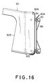
- the sheet pressing mechanism includes base plate 60 which is fastened to the main frame 10.
- the base plate 60 has a plurality of (three in this embodiment) guide pins 60A fixed to it.
- a slide plate 62 is arranged to be slidable forward and backward by fitting the guide pins 60A into respective slots 62A formed through it.
- a spring 64 is extended between the forward end of the base plate 60 and the rear end of the slide plate 62 to spring bias the slide plate 62 forward.
- the slide plate 62 has a pair of guide pins 62B fixed to it, and a slider 66 is provided to be slidable forward and backward by inserting the guide pins 62B into respective slots 66A formed through the slider 66.
- a touch plate 66B is mounted to a forward end of the slider 66, and is designed to be pushed backward by coming into abutment against the rear side wall 12D of a tray 121-12 n which is being pulled backward by the tray drawing out mechanism.
- a sheet pressing lever 68 is rotatably supported at an intermediate portion thereof on a supporting pin 62C which is fixed to a forward portion of the slide plate 62.
- a forward portion of the sheet pressing lever 68 is curved forwardly, and has a pressing roller 68A rotatably supported on the forward end thereof.
- the rear end of the sheet pressing lever 68 is related to the slider 66 through a first link 70 and a second link 72. More specifically, the links 70 and 72 are rotatably supported on a supporting pins 62D and 62E mounted on the slide plate 62, respectively.
- the links 70 and 72 are connected at one ends thereof through a connection pin 74.
- connection pin 68B mounted on the rear end of the sheet pressing lever 68 is fitted into a slot 70A formed through the other end of the first link 70 whilst a connection pin 66C fixed to an intermediate portion of the slider 66 passes through a slot 72A formed through the other end of the second link 72.
- a spring 76 is provided between the one end of the first link 70 and the rear end of the slide plate 62.
- the slider 66 is hence biased forwardly while the sheet holding lever 68 is urged in a direction to raise the holding roller 68A.
- Each tray 12 is pulled rearward by the tray drawing out mechanism, and the rear side wall 12D of the tray thereby moves from an aligned position P0 in Fig. 18 to a maximum drawn out position P2 through an intermediate drawn out position P1.
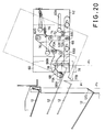
- the slider 66 is firstly pushed and moved backward relative to the slide plate 62, and the sheet pressing lever 68 is then swung in the counter-clockwise direction in Fig. 19 to depress the sheets on the tray. Thereafter, as shown in Fig. 20, the slide plate 62 and the slider 66 in unison move backwardly relative to the base plate 60 together with the tray 12 with the sheets on it pressed by the sheet pressing lever 68.
- the spring 64 which biases the slide plate 62 is expanded after the spring 76 which urges the slider 66 is expanded. For this reason, the biasing force of the spring 76 is designed to be smaller than that of the spring 64.
- the portion of the stack of sheets placed above the cutout 12E of the rear right corner thereof is guided between upper and lower sheets guides 77A and 77B and then stapled.
- the sheet guides 77A and 77B are secured at predetermined positions of the main frame 10 in casing body A.
- photosensor 78 is provided to the sheet guides 77A and 77B for detecting whether or not sheets are present at the stapling position.
- Electric signals of information such as the number of pages and the number of copies of a document to be copied are sent from a host machine, not shown, to a sorter control unit provided to the casing body A .
- the host machine is a photocopier, for example and the sorter control unit is constituted by a microcomputer not shown.
- the motor 50 is energized, and the Geneva wheel assemblies 40 and 42 are thereby rotated in the same direction.
- This causes the rear tray pins 12G and 12H of each trays 121-12 n to engage with respective grooves 40C and 42C, and the trays are sequentially shifted downwardly.
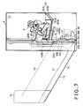
- the uppermost tray 121 is, as shown in Fig. 7, positioned just below the outlet of the guide plates 80A and 80B of the sheet putting aside mechanism, and thus the sorter is placed in a tray initial state.
- the rear pins 12G1 and 12H1 of the uppermost tray 121 come into contact with the circumferential surfaces of the lower Geneva wheels 402 and 422 in the first slots 10C and 10D, respectively.
- the dummy pins 16D and 18D of the tray carrier 15 are, as shown by the dots-and-dash line in Fig. 9, engaged with the grooves 40C1 and 42C1 of the upper Geneva wheels 401 and 421, are thereby guided rearwardly, and are then disengaged. In this event, the dummy pins 16D and 18D are urged against the outer circumferential surfaces of the Geneva wheels 421 and 422; 401 and 402 by the springs 10G, respectively.
- a copied sheet is introduced into the transporting guide 20, through which it is discharged on the uppermost tray 121 by the pinch rollers 82 and feed rollers 84 of the sheet putting aside mechanism driven by the motor 32.
- the sheet putting aside mechanism changes the direction of the feed rollers 84 according to the control sequence shown by a flow chart of Fig. 23.
- step S1 of the control sequence the sheet putting aside mechanism is initialized, thereby directing the feed rollers 84 forward (leftward in Fig. 12) and starting driving them.
- step S2 After the detection of a sheet by the first passage sensor 114 is confirmed in step S2, the direction of the feed rollers 84 is changed to turn 15° counterclockwise in Fig. 12 (as shown by broken lines) in step S3.
- step S4 it is judged whether or not the second passage sensor 116 detects the edge of the sheet.
- step S5 the feed rollers 84 is returned to the original direction. Thereafter, the routine is returned to step S2.
- a sheet is moved forwardly and rightwardly (downwardly in Fig. 12), and are discharged on a tray 12 in this fashion.
- the sheet dropped on the tray slides down the inclined surface of the bottom wall by gravity and is aligned by the right side wall 12B and the rear side wall 12D of the tray.
- the control unit sends a signal to energize the motor 50, and the Geneva wheel assemblies 40 and 42 are thereby rotated to shift trays 12 upwardly.
- Fig. 21(A) illustrates a state in which a sheet is dischargeable to the fourth tray 124 from the top.
- the rear tray pin 12G4 of the tray 124 is in contact with the circumferential surface of the lower Geneva wheel 402.
- the third rear tray pin 12G3 is positioned at the extended portion 10C3, and is out of engagement with the groove 40C1 of the Geneva wheel 401 and the groove 40C2 of the Geneva wheel 402.
- the rear tray pin 12G3 is held against the circumferential surfaces of the Geneva wheels 401 and 402 by the return spring 10G.
- the tray section B is opened between the third tray 123 and the fourth tray 124.
- the groove 40C1 of the Geneva wheel 401 and the groove 40C2 of the Geneva wheel 402 are, as shown in Fig. 21(A), positioned with a predetermined difference in phase.
- the Geneva wheels 401 and 402 (421 and 422) are turned in respective directions shown by arrows.
- the rear tray pin 12G3 is then pushed into the groove 40C1 during rotation of the Geneva wheel 401, and when the Geneva wheels 401 and 402 reach positions shown in Fig. 21(B), the Geneva wheel 401 transports the rear tray pin 12G3 to the inlet of the vertical portion 10C4 of the first slot 10C.
- the groove 40C2 of the lower Geneva wheel 402 is located at a lower position.
- the Geneva wheels 401 and 402 are further rotated from the state of Fig. 21(B), and in a state shown in Fig. 21(C) the third rear tray pin 12G3 is disengaged from the groove 40C1 of the Geneva wheel 401.
- the fourth rear tray pin 12G4 fits in the groove 40C2 of the lower Geneva wheel 402.
- the Geneva wheels 401 and 402 are further turned from the state of Fig. 21(D) to the state of Fig. 21(E), during which the fourth rear tray pin 12G4 is guided by the extended portion 10C3 of the first slot 10C, and is then disengaged from the groove 40C2 of the lower Geneva wheel 402.
- the fourth rear tray pin 12G4 is held between the circumferential surfaces of the Geneva wheels 401 and 402 and the return spring 10G.
- each of the Geneva wheels 401 and 402 makes one revolution, so that the shift operation of the tray is completed as well as the drawing out operation of the next tray.
- the guiding of the rear tray pins 12G and 12H in the tray drawing out operation is carried out by the extended portion 10C3 which extends in the common tangent direction of the Geneva wheels 401 and 402, and the rearward displacement of the rear portion of each tray is achieved without considerable vertical movement.
- the shifting operation of trays is carried out according to the number of the copies of the document.
- the rear tray pins 12G and 12H of each of trays are moved upwardly rearwardly while guided in the respective first slots 10C and 10D.
- the front tray pins 12I and 12J of each of trays are raised obliquely upwardly while they are guided by respective inclined guide grooves 14A, 14A of the front guide members 14, 14.
- the guide grooves 14A are formed in a V-shape as shown in Fig. 22, each having a downwardly inclined front portion and an upwardly inclined rear portion. This enables the space between a tray, on which a sheet discharged is received, and an upper tray positioned just above the tray to be enlarged to thereby increase the receiving space of sheets in the tray. The discharging operation of the sheet is thus facilitated.
- the trays 121-12 n are returned to the tray initial state by reversing the motor 50. Then, the sorting operation is performed for the next page.
- the stapling operation When copying of all the pages is finished, the stapling operation will be conducted.
- the stapling operation is carried out on sheets stacked on the tray which has been pulled rearwardly.
- the pulling out operation of trays is performed simultaneously with the sequential shifting operation of trays 121-12 n from the tray initial state.
- the shifts number counter is reset by activating the lower limit detection switch 58.
- the position detection switch 56 is actuated by the cam 54 every revolution of the Geneva wheels 401 and 421, so that it is detected what tray from the top is placed at the drawn out position.
- the sorter control unit has a construction shown by the functional blocks of Fig. 25.
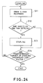
- Fig. 24 illustrates a flow chart for carrying out the stapling operation by shifting the trays 121-12 n stepwisely.
- a tray is drawn rearwardly (step S11), and then the sensor 78 detects whether or not sheets are placed on the tray (step S12). Subsequently, the stapling operation is performed if sheets are placed on the tray (step S13).
- steps S11-S13 are repeated by a predetermined number, and when it is judged that a predetermine number of the stapling operations are conducted (step S14), the routine is ended.
- the sheet pressing mechanism is actuated, so that sheets on trays are depressed not to separate. The sheets are thus certainly stapled in an aligned stacked condition.
- a tray is stationarily held in the drawn out position, and the stapling operation is surely carried out. Moreover, it is not necessary to stop the Geneva wheel assemblies 40 and 42 every stapling operation, so that load on the motor 50 is reduced. It is, however, possible to stop the motor 50 and the Geneva wheels 401 and 402: 421 and 422 every stapling operation, and even if there is somewhat a scattering in the stop position of the Geneva wheels 401 and 402: 421 and 422, the tray is held in the stationary position so that the positioning accuracy of the tray is secured.
- the control of the direction of the feed rollers 84 of the sheet putting aside mechanism may be performed by a control unit of a host machine other than a sorter control unit, the host machine including, for example, a photocopier which discharges sheets.
- a modified embodiment of this invention is shown in Figs. 26 and 27, in which the sensor 78 is changed in position.
- a pair of members 78A and 78B which include light emitting and receiving elements respectively are disposed on an upper arm 79A and lower arm 79B, respectively.
- the upper and lower arms 79B and 79A are away from the sheet guides 77A and 77B.
- the arms 79A and 79B are integrally formed with the right side frame 10A by molding.
Landscapes
- Collation Of Sheets And Webs (AREA)
- Folding Of Thin Sheet-Like Materials, Special Discharging Devices, And Others (AREA)
Claims (7)
- Trieur qui comprend :
une pluralité de bacs (12₁-12n) destinés à recevoir et empiler des feuilles (5) sur eux, les feuilles (5) étant éjectées d'une zone prédéterminée d'éjection des feuilles.;
des moyens (E) servant à agrafer les feuilles sur les bacs (12₁-12n) dans une position de travail ;
des moyens (10C, 10D, 40, 42) destinés à déplacer successivement les plateaux (12₁-12n) entre la zone d'éjection des feuilles et la position de travail ; caractérisé en ce que des moyens (68) de compression des feuilles sont prévus pour comprimer les feuilles (5) de haut en bas contre les bacs correspondants (12₁-12n) dans une action liée au mouvement des bacs vers la position de travail. - Trieur selon la revendication 1, caractérisé en ce que les moyens de compression des feuilles comprennent :
une base (60) agencée dans le voisinage de la position de travail à laquelle ledit bac (12) de support de feuilles est transporté en séquence dans une direction de transport des bacs,
un premier élément mobile (62) agencé sur ladite base (60) pour se déplacer en mouvement alternatif dans la direction de transport des bacs ;
un deuxième moyen mobile (66) agencé sur ledit premier élément mobile (62) pour pouvoir se déplacer en mouvement alternatif dans la direction de transport des bacs, le deuxième moyen mobile (66) étant adapté pour entrer en contact avec chaque bac (12) transporté à la position de travail ;
des premiers moyens de sollicitation (64) servant à solliciter le premier élément mobile (62) dans une direction opposée de la direction de transport des bacs ;
des deuxièmes moyens de sollicitation (F6) servant à solliciter le deuxième élément mobile (66) dans une direction opposée à la direction de transport des plateaux avec une force de sollicitation plus petite que la force de sollicitation des premiers moyens de sollicitation (64) ;
un bras presseur (68) destiné à se rapprocher et s'éloigner des feuilles contenues dans chaque bac (12) placé dans la position de travail ; et
des moyens de liaison (70, 72) agencés entre ledit bras presseur (68) et ledit deuxième élément mobile (66) pour déplacer le bras presseur (68) lorsque les premiers et deuxièmes éléments mobiles (62, 66) sont déplacés l'un par rapport à l'autre. - Trieur selon la revendication 2, caractérisé en ce que lesdits moyens de liaison (70, 72) comprennent une première biellette (70) et une deuxième biellette (72), chacune des première et deuxième biellettes étant montée pivotante sur ledit premier moyen mobile (62) par l'intermédiaire d'une tige de support (62D, 62E) ; ledit bras presseur possède une extrémité proximale et une extrémité distale ; ladite première biellette (70) est reliée par une de ses extrémités à l'extrémité proximale dudit bras presseur (68) et, par l'autre extrémité, à une des extrémités de ladite deuxième biellette (72) ; et ladite deuxième biellette (72) est reliée à l'autre extrémité dudit deuxième élément mobile (66).
- Trieur selon la revendication 3, caractérisé en ce que les deuxièmes moyens de sollicitation comprennent un ressort (76) tendu entre ladite première biellette (70) et ledit premier élément mobile (62).
- Trieur selon la revendication 3, caractérisé en ce que ledit bras presseur (68) comprend un rouleau presseur (68A) monté rotatif sur l'extrémité distale dudit bras presseur.
- Trieur selon la revendication 1 ou 2, caractérisé en ce que chacun des bacs (12₁, 12n) comprend des moyens servant à définir une échancrure (12E) et lesdits moyens d'agrafage comprennent une agrafeuse (E) destinée à agrafer les feuilles (S) dans l'échancrure (12E) de chaque bac (12).
- Trieur selon la revendication 6, comprenant en outre des moyens capteurs (78) placés dans le voisinage de la position de travail, pour détecter une feuille placée dans l'échancrure (12E) afin de produire un signal de détection, ladite agrafeuse (E) étant commandée en réponse au signal de détection.
Applications Claiming Priority (4)
| Application Number | Priority Date | Filing Date | Title |
|---|---|---|---|
| JP2180501A JP2738973B2 (ja) | 1990-07-10 | 1990-07-10 | ソータ |
| JP180501/90 | 1990-07-10 | ||
| JP2180505A JP2895174B2 (ja) | 1990-07-10 | 1990-07-10 | 被処理物の押さえ装置 |
| JP180505/90 | 1990-07-10 |
Publications (3)
| Publication Number | Publication Date |
|---|---|
| EP0465762A2 EP0465762A2 (fr) | 1992-01-15 |
| EP0465762A3 EP0465762A3 (en) | 1992-03-04 |
| EP0465762B1 true EP0465762B1 (fr) | 1995-08-23 |
Family
ID=26500006
Family Applications (1)
| Application Number | Title | Priority Date | Filing Date |
|---|---|---|---|
| EP91103005A Expired - Lifetime EP0465762B1 (fr) | 1990-07-10 | 1991-02-28 | Classeur pour articles comprenant une presse. |
Country Status (3)
| Country | Link |
|---|---|
| US (1) | US5110102A (fr) |
| EP (1) | EP0465762B1 (fr) |
| DE (1) | DE69112306T2 (fr) |
Families Citing this family (4)
| Publication number | Priority date | Publication date | Assignee | Title |
|---|---|---|---|---|
| JPH0813582B2 (ja) * | 1990-10-29 | 1996-02-14 | 三田工業株式会社 | 用紙後処理装置 |
| US5599009A (en) * | 1995-10-05 | 1997-02-04 | Xerox Corporation | Stacking height estimation correction system |
| US6773004B2 (en) | 2002-12-06 | 2004-08-10 | Hewlett-Packard Development Company, L.P. | Methods and apparatus to estimate the thickness of a sheet stack |
| JP4065866B2 (ja) * | 2004-09-22 | 2008-03-26 | シャープ株式会社 | シート堆積装置およびそれを備えてなる画像形成装置 |
Citations (2)
| Publication number | Priority date | Publication date | Assignee | Title |
|---|---|---|---|---|
| JPS6443456A (en) * | 1987-08-10 | 1989-02-15 | Canon Kk | Sheet post-processor |
| JPH01231757A (ja) * | 1988-03-11 | 1989-09-18 | Canon Inc | シート後処理装置 |
Family Cites Families (24)
| Publication number | Priority date | Publication date | Assignee | Title |
|---|---|---|---|---|
| US3988018A (en) * | 1975-02-25 | 1976-10-26 | Van Dyke Research Corporation | Paper sorter |
| JPS5593764A (en) * | 1978-12-29 | 1980-07-16 | Ricoh Co Ltd | Collater |
| US4691914A (en) * | 1986-01-21 | 1987-09-08 | Gradco Systems, Inc. | Sheet receiver |
| US4762312A (en) * | 1986-04-15 | 1988-08-09 | Ricoh Company, Ltd. | Sorter with a function of binding copy sheets |
| JPH075211B2 (ja) * | 1986-05-13 | 1995-01-25 | キヤノン株式会社 | シ−ト後処理装置 |
| JPS6351191A (ja) * | 1986-08-21 | 1988-03-04 | 株式会社リコー | 製本装置 |
| JP2772635B2 (ja) * | 1986-10-28 | 1998-07-02 | 株式会社リコー | 製本装置 |
| JPH0769640B2 (ja) * | 1986-10-28 | 1995-07-31 | 株式会社リコー | 製本装置 |
| JPS63180676A (ja) * | 1987-01-21 | 1988-07-25 | Canon Inc | シ−ト分離装置 |
| JPS63180673A (ja) * | 1987-01-22 | 1988-07-25 | Canon Inc | シ−ト整合トレイ装置 |
| JP2589305B2 (ja) * | 1987-04-10 | 1997-03-12 | キヤノン株式会社 | シート後処理装置 |
| JPS6312564A (ja) * | 1987-05-29 | 1988-01-19 | Ricoh Co Ltd | 製本装置 |
| JPS6359591A (ja) * | 1987-05-29 | 1988-03-15 | 株式会社リコー | 製本装置 |
| JPH0620970B2 (ja) * | 1987-07-09 | 1994-03-23 | キヤノン株式会社 | ステープラ付シート分類装置 |
| JPH0633009B2 (ja) * | 1987-07-30 | 1994-05-02 | キヤノン株式会社 | シ−ト後処理装置 |
| JPH0635219B2 (ja) * | 1987-08-10 | 1994-05-11 | キヤノン株式会社 | シ−ト分類装置 |
| JPH0637118B2 (ja) * | 1987-07-30 | 1994-05-18 | キヤノン株式会社 | シ−ト後処理装置 |
| EP0631201B1 (fr) * | 1987-07-30 | 1998-10-28 | Canon Kabushiki Kaisha | Dispositif de tri de feuilles |
| JPS6464973A (en) * | 1987-09-04 | 1989-03-10 | Minolta Camera Kk | Sorter provided with finisher |
| JPH0639063B2 (ja) * | 1988-03-11 | 1994-05-25 | キヤノン株式会社 | シート分類・綴じ装置 |
| JPH01236163A (ja) * | 1988-03-12 | 1989-09-21 | Canon Inc | シート後処理装置 |
| JP2702504B2 (ja) * | 1988-05-06 | 1998-01-21 | 株式会社リコー | ソーターのステープル装置 |
| EP0346851B1 (fr) * | 1988-06-14 | 1994-12-14 | Canon Kabushiki Kaisha | Dispositif d'opération complémentaire pour des feuilles |
| US5026034A (en) * | 1989-06-19 | 1991-06-25 | Eastman Kodak Company | Document output apparatus having anti-dishevelment device |
-
1991
- 1991-02-26 US US07/661,329 patent/US5110102A/en not_active Expired - Lifetime
- 1991-02-28 EP EP91103005A patent/EP0465762B1/fr not_active Expired - Lifetime
- 1991-02-28 DE DE69112306T patent/DE69112306T2/de not_active Expired - Fee Related
Patent Citations (2)
| Publication number | Priority date | Publication date | Assignee | Title |
|---|---|---|---|---|
| JPS6443456A (en) * | 1987-08-10 | 1989-02-15 | Canon Kk | Sheet post-processor |
| JPH01231757A (ja) * | 1988-03-11 | 1989-09-18 | Canon Inc | シート後処理装置 |
Also Published As
| Publication number | Publication date |
|---|---|
| EP0465762A2 (fr) | 1992-01-15 |
| EP0465762A3 (en) | 1992-03-04 |
| DE69112306T2 (de) | 1996-05-02 |
| US5110102A (en) | 1992-05-05 |
| DE69112306D1 (de) | 1995-09-28 |
Similar Documents
| Publication | Publication Date | Title |
|---|---|---|
| EP0465764B1 (fr) | Transporteur et appareil classeur pour cela | |
| EP0298510B1 (fr) | Trieuse de feuilles comprenant une agrafeuse | |
| EP0301594B1 (fr) | Trieuse de feuilles comprenant une agrafeuse | |
| US4930761A (en) | Control method for sorter with stapler | |
| JP2695026B2 (ja) | スティプラ付ソータ | |
| US5110102A (en) | Article pressing device and sorter with the same | |
| EP0465761B1 (fr) | Trieuse | |
| EP0465763B1 (fr) | Trieuse | |
| US5673906A (en) | Sheet post-treating apparatus | |
| JP2895174B2 (ja) | 被処理物の押さえ装置 | |
| JP2857475B2 (ja) | 被搬送物の幅寄せ装置 | |
| JPH07232852A (ja) | ソーター | |
| JP2738973B2 (ja) | ソータ | |
| JP2798296B2 (ja) | ソータ | |
| US5580038A (en) | Sheet post-treating apparatus | |
| EP0494347B1 (fr) | Appareil classeur contenant un dispositif d'empilage | |
| JP3343043B2 (ja) | スタッカ | |
| JP2610934B2 (ja) | シ−ト分類・綴じ装置を備えた画像形成装置 | |
| JP2675736B2 (ja) | パンチ装置 | |
| JPH04235859A (ja) | ステイプラ装置を備えたソータ | |
| JP3281024B2 (ja) | ソータ | |
| JPH04292370A (ja) | ステイプラ装置を備えたソータ | |
| JPH04312893A (ja) | ステイプラ装置を備えたソータ | |
| JPH04241998A (ja) | ステイプラ装置を備えたソータ | |
| JPH03297694A (ja) | 画像形成装置 |
Legal Events
| Date | Code | Title | Description |
|---|---|---|---|
| PUAI | Public reference made under article 153(3) epc to a published international application that has entered the european phase |
Free format text: ORIGINAL CODE: 0009012 |
|
| PUAL | Search report despatched |
Free format text: ORIGINAL CODE: 0009013 |
|
| 17P | Request for examination filed |
Effective date: 19910228 |
|
| AK | Designated contracting states |
Kind code of ref document: A2 Designated state(s): DE FR GB |
|
| AK | Designated contracting states |
Kind code of ref document: A3 Designated state(s): DE FR GB |
|
| 17Q | First examination report despatched |
Effective date: 19930813 |
|
| GRAA | (expected) grant |
Free format text: ORIGINAL CODE: 0009210 |
|
| AK | Designated contracting states |
Kind code of ref document: B1 Designated state(s): DE FR GB |
|
| PG25 | Lapsed in a contracting state [announced via postgrant information from national office to epo] |
Ref country code: FR Free format text: THE PATENT HAS BEEN ANNULLED BY A DECISION OF A NATIONAL AUTHORITY Effective date: 19950823 |
|
| REF | Corresponds to: |
Ref document number: 69112306 Country of ref document: DE Date of ref document: 19950928 |
|
| EN | Fr: translation not filed | ||
| PLBE | No opposition filed within time limit |
Free format text: ORIGINAL CODE: 0009261 |
|
| STAA | Information on the status of an ep patent application or granted ep patent |
Free format text: STATUS: NO OPPOSITION FILED WITHIN TIME LIMIT |
|
| 26N | No opposition filed | ||
| REG | Reference to a national code |
Ref country code: GB Ref legal event code: IF02 |
|
| PGFP | Annual fee paid to national office [announced via postgrant information from national office to epo] |
Ref country code: GB Payment date: 20040224 Year of fee payment: 14 |
|
| PGFP | Annual fee paid to national office [announced via postgrant information from national office to epo] |
Ref country code: DE Payment date: 20040227 Year of fee payment: 14 |
|
| PG25 | Lapsed in a contracting state [announced via postgrant information from national office to epo] |
Ref country code: GB Free format text: LAPSE BECAUSE OF NON-PAYMENT OF DUE FEES Effective date: 20050228 |
|
| PG25 | Lapsed in a contracting state [announced via postgrant information from national office to epo] |
Ref country code: DE Free format text: LAPSE BECAUSE OF NON-PAYMENT OF DUE FEES Effective date: 20050901 |
|
| GBPC | Gb: european patent ceased through non-payment of renewal fee |
Effective date: 20050228 |