EP0487516A1 - Appareil et méthode de construction - Google Patents
Appareil et méthode de construction Download PDFInfo
- Publication number
- EP0487516A1 EP0487516A1 EP92200399A EP92200399A EP0487516A1 EP 0487516 A1 EP0487516 A1 EP 0487516A1 EP 92200399 A EP92200399 A EP 92200399A EP 92200399 A EP92200399 A EP 92200399A EP 0487516 A1 EP0487516 A1 EP 0487516A1
- Authority
- EP
- European Patent Office
- Prior art keywords
- construction
- framework
- building
- completed structure
- working space
- Prior art date
- Legal status (The legal status is an assumption and is not a legal conclusion. Google has not performed a legal analysis and makes no representation as to the accuracy of the status listed.)
- Granted
Links
- 238000010276 construction Methods 0.000 title claims abstract description 173
- 230000003028 elevating effect Effects 0.000 claims abstract description 29
- 230000007246 mechanism Effects 0.000 claims abstract description 25
- 230000001174 ascending effect Effects 0.000 claims abstract description 3
- 238000003466 welding Methods 0.000 claims description 12
- 239000004035 construction material Substances 0.000 claims description 5
- 238000009434 installation Methods 0.000 claims description 3
- 238000000034 method Methods 0.000 description 4
- 238000004891 communication Methods 0.000 description 1
- 230000001419 dependent effect Effects 0.000 description 1
- 230000007613 environmental effect Effects 0.000 description 1
- 238000009408 flooring Methods 0.000 description 1
- 238000005192 partition Methods 0.000 description 1
- 239000011295 pitch Substances 0.000 description 1
- 230000001681 protective effect Effects 0.000 description 1
Images

Classifications
-
- E—FIXED CONSTRUCTIONS
- E04—BUILDING
- E04G—SCAFFOLDING; FORMS; SHUTTERING; BUILDING IMPLEMENTS OR AIDS, OR THEIR USE; HANDLING BUILDING MATERIALS ON THE SITE; REPAIRING, BREAKING-UP OR OTHER WORK ON EXISTING BUILDINGS
- E04G21/00—Preparing, conveying, or working-up building materials or building elements in situ; Other devices or measures for constructional work
- E04G21/24—Safety or protective measures preventing damage to building parts or finishing work during construction
- E04G21/28—Safety or protective measures preventing damage to building parts or finishing work during construction against unfavourable weather influence
-
- E—FIXED CONSTRUCTIONS
- E04—BUILDING
- E04B—GENERAL BUILDING CONSTRUCTIONS; WALLS, e.g. PARTITIONS; ROOFS; FLOORS; CEILINGS; INSULATION OR OTHER PROTECTION OF BUILDINGS
- E04B1/00—Constructions in general; Structures which are not restricted either to walls, e.g. partitions, or floors or ceilings or roofs
- E04B1/35—Extraordinary methods of construction, e.g. lift-slab, jack-block
- E04B1/3522—Extraordinary methods of construction, e.g. lift-slab, jack-block characterised by raising a structure and then adding structural elements under it
- E04B1/3527—Extraordinary methods of construction, e.g. lift-slab, jack-block characterised by raising a structure and then adding structural elements under it the structure being a roof
-
- E—FIXED CONSTRUCTIONS
- E04—BUILDING
- E04G—SCAFFOLDING; FORMS; SHUTTERING; BUILDING IMPLEMENTS OR AIDS, OR THEIR USE; HANDLING BUILDING MATERIALS ON THE SITE; REPAIRING, BREAKING-UP OR OTHER WORK ON EXISTING BUILDINGS
- E04G21/00—Preparing, conveying, or working-up building materials or building elements in situ; Other devices or measures for constructional work
- E04G21/24—Safety or protective measures preventing damage to building parts or finishing work during construction
- E04G21/242—Safety or protective measures preventing damage to building parts or finishing work during construction for temporarily covering the whole worksite, e.g. building, trench
-
- E—FIXED CONSTRUCTIONS
- E04—BUILDING
- E04B—GENERAL BUILDING CONSTRUCTIONS; WALLS, e.g. PARTITIONS; ROOFS; FLOORS; CEILINGS; INSULATION OR OTHER PROTECTION OF BUILDINGS
- E04B1/00—Constructions in general; Structures which are not restricted either to walls, e.g. partitions, or floors or ceilings or roofs
- E04B1/35—Extraordinary methods of construction, e.g. lift-slab, jack-block
- E04B2001/3588—Extraordinary methods of construction, e.g. lift-slab, jack-block using special lifting or handling devices, e.g. gantries, overhead conveying rails
-
- Y—GENERAL TAGGING OF NEW TECHNOLOGICAL DEVELOPMENTS; GENERAL TAGGING OF CROSS-SECTIONAL TECHNOLOGIES SPANNING OVER SEVERAL SECTIONS OF THE IPC; TECHNICAL SUBJECTS COVERED BY FORMER USPC CROSS-REFERENCE ART COLLECTIONS [XRACs] AND DIGESTS
- Y10—TECHNICAL SUBJECTS COVERED BY FORMER USPC
- Y10S—TECHNICAL SUBJECTS COVERED BY FORMER USPC CROSS-REFERENCE ART COLLECTIONS [XRACs] AND DIGESTS
- Y10S52/00—Static structures, e.g. buildings
- Y10S52/12—Temporary protective expedient
Definitions
- the present invention relates to a construction apparatus and a construction method advantageously applicable to carrying out the construction of various structures including low buildings and high buildings using the least necessary labor and capable of enabling the construction work to be carried out regardless of weather conditions.
- a conventional construction method In constructing a multistory building, a conventional construction method erects columns for all the stories, lifts up the component members of the multistory building preassembled on the ground including slabs by lifting machines including cranes, and then joins the component members to the columns. Another conventional construction method stacks up stories one on another by completing a lower story, and then lifting the component members of an upper story by lifting machines including cranes and assembling the component members on the lower story.
- Fig. 1 is an illustration of the latter conventional construction method, in which the first and second stories of a building have been completed and the third story is under construction.
- a worker H standing on the floor of the third story receives building members S lifted by a crane C, and then the worker H assembles the building members S by fixing the building members S at predetermined positions by suitable means including welding and bolts.
- J. P. Pat. Provisional Pub. (Kokai) No. 62-244941 proposes a construction method which completes one story of a building in a plant installed in the first story of the building by using machines including industrial robots, and then pushes up the complete story by a distance corresponding to the story height. This procedure is repeated to complete a multistory building.
- DE-C-929089 describes a protective hut with working platforms and conveying devices which can be used around a transverse wall of a building under construction. It comprises four hydraulically adjustable supports to enable its height to be altered according to the progress of the work.
- the invention provides a construction method of constructing a multistory building in ascending order of stories by sequentially repeating steps of:
- the invention also provides a construction apparatus comprising:
- the elevating and locking means provided on the framework are fastened to the columns supported on the columns to hold the framework firmly on the underlying completed structure. Since the elevating and locking means are locked to the columns during construction work within the working space, the vibration resistance of the construction apparatus can be sufficiently secured throughout the construction work.
- the elevating and locking means are unlocked, the framework is elevated along the columns to form another working space, and then the elevating and locking means is locked again to the columns.
- the elevating and locking means are locked to the columns, the columns serve as members for forming the working space to support the framework.
- permanent columns are erected one by one in the working space and beams are joined firmly to the permanent columns by construction means to complete a structure for the next upper story on the underlying completed structure.
- Such a construction work including forming a working space and constructing a structure is repeated to construct structures for the upper stories sequentially.
- the construction work is advanced upward in steps by alternately repeating the elevation and locking of the framework to form working spaces sequentially.
- the elevation of the framework and the operation of the construction means can be easily controlled automatically, and the construction apparatus, in cooperation with automatic construction equipments, enables automatic construction work.
- the framework is provided with a covering for covering the working space to shield the working space from the outside, and hence the construction work can be carried out regardless of weather conditions without giving public nuisance to the environment.
- the columns are provided with racks respectively, and the elevating and locking means are provided with pinions respectively.
- the combination of the columns and the elevating and locking means may be a screw-and-rod mechanism, a center hole jack mechanism or a hydraulic jack mechanism.
- the construction means include column erecting robots, column welding robots, beam welding robots and external wall installing robots.
- the columns may be either temporary columns or permanent columns.
- the framework may be provided with traveling cranes and construction robots mounted on the traveling cranes.
- the traveling cranes and the construction robots are controlled on a cylindrical coordinate system or a polar coordinate system.
- Lifts for lifting up construction materials may be installed in the internal space of the structure, and each lift may be provided with a rotary floor to unloaded the construction materials selectively at a desired position.
- a control room may be constructed in the upper space of the framework.
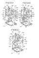
- the construction apparatus comprises, as the essential components, a framework construction 103 installed above a completed structure of a building 110 to form a working space 114 in which permanent columns 106 are installed and the construction work is carried out over the completed structure of the building 110, guide posts 140 removably supported on the completed structure of the building 110, elevating and locking mechanisms 150 provided on the framework construction 103 to lock the framework 103 to the guide posts 140 so that the framework construction 103 can be fixed to the completed structure of the building 110 and to elevate the framework construction 103 in forming the working space 114 between the framework construction 103 and the completed structure of the building 110, extension devices 101 provided on the framework construction 103 and capable of extending downward to press the permanent columns 106 against the completed structure of the building 110, and construction equipments for the construction work in the working space 114.
- the construction equipments include a column welding robot 104, a column installing robot 109, a beam welding robot 112, and a wall installing robot, not shown.
- the framework construction 103 may be provided with a cover 116 for covering the working space 114.
- Each of the guide posts 140 is provided longitudinally with a rack 141.
- Each of the elevating and locking mechanisms 150 comprise a pinion 151 engaging the rack 141.
- four extension devices 101 are hydraulic cylinders each having a rod 102 capable of moving by a stroke slightly greater than the story height of the building 110.
- the hydraulic cylinders may be substituted by the device shown in Fig. 3(A) or 3(B).
- Fig. 3(A) shows a combination of a rod 2 provided with a rack 20 along the entire length thereof, a sheath 13 fixed to the framework 3 and slidably receiving the rod 2 therein, and a pinion 21 rotatably supported on the sheath 13 and engaging the rack 20 to extend or contract the rod 2 along the sheath 13.
- Fig. 3(B) shows a combination of a rod 2 externally provided with helical thread 22, and a sheath 13 internally provided with a helical groove 23 engaging the helical thread 22 of the rod 2, which is similar to a screw jack. The rod 2 is extended or contracted by rotating the rod 2 relative to the sheath 13.
- the shape of the framework 103 is substantially the same in the plan as that of the top surface of the building 110.
- the framework 103 is rectangular in the plan.
- the extension devices 101 are attached to the framework 103, respectively, at the four corners of the same.
- a travelling crane 105 is mounted on the opposite frame members 103a and 103b of the framework 103, and one of the construction equipments, for example the column installing robot 109, is held on the traveling crane 105.
- the guide posts 140 are set upright, fastened temporarily at the lower ends thereof to beams of the completed structure of the building 110, and slidably received through guide rings 131 provided on pairs of frame members 103c and 103d, respectively.
- the racks 141 are welded to the guide posts 140 in suitable pitches so as to extend longitudinally along the guide posts 140, respectively.
- the pinions 151 are provided on the frame members 103d so as to engage the racks 141. Each pinion is driven by a driving source such as a motor.
- the rack 141, the pinion 151 and the driving source constitute the elevating and locking mechanism 150.
- Each of the elevating and locking mechanisms 150 may be a screw rod mechanism, a center hole jack mechanism or a hydraulic jack mechanism.
- the framework 103 of the construction apparatus is held securely relative to the completed structure of the building 110 by the engagement of the pinions 151 of the elevating and locking mechanisms 150 with the racks 141 fixed to the guide posts 140 supported on the completed structure of the building 110.
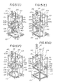
- the framework 103 is elevated by driving the pinions 151 of the elevating and locking mechanisms 150 to form the working space 114 over the completed structure of the building 110, and the rods 102 of the extension columns 101 are fully retracted to form spaces 115 for receiving permanent columns 106 directly below the rods 102 as shown in Fig. 5(A).
- the permanent columns 106 are installed, respectively, in the spaces 115 by the column installing robot 109 as shown in Fig. 5(B).
- the permanent column 106 is positioned correctly since the rod 102 of one of the extension columns 101 is extended slightly to press the permanent column 106 at the upper end 106a thereof against the upper end of a corresponding member of the completed structure of the building 110, and then the lower end of the permanent column 106 is welded to the upper end of the corresponding member of the completed structure of the building 110 by the welding robot 104 held on the traveling crane 105.
- the stroke of the rods 102 of the extension columns 101 may be as small as a value sufficient to press the permanent columns 106 against the completed structure of the building 110, the stroke is set as large as the story height of the building 110 to enable the extension columns 101 to serve as temporary columns for supporting the framework 103 on the completed structure of the building 110 in this embodiment.
- the adjacent permanent column 106 is installed and fixed in place in the same manner
- beams 107 previously joined to the adjacent permanent columns 106 so as to extend toward each other are welded together by the welding robot 112 held on the traveling crane 105. It is also possible to place a beam 107 having a length corresponding to the span between opposite beam joints attached to the opposite sides of the adjacent permanent columns 106 and to weld the beam 107 to the beam joints by the welding robot 112.
- the foregoing construction procedure is repeated to complete the skeleton of an upper story on the previously completed structure of the building 110 by fixedly installing all the permanent columns 106 and joining together the beams 107 as shown in Fig. 5(F). Subsequently, the guide posts 140 are raised to positions shown in Fig. 5(G), and then finishing work necessary for completing the story is carried out to complete the upper story.
- the finishing work includes setting external walls 111 on the skeleton (Fig. 6), installing partitions, constructing booths including a service room, a bathroom and a lavatory, installing utensils and equipments, flooring the slabs and hanging the ceiling.
- the elevating and locking mechanisms 150 are driven to elevate the framework 103 as shown in Fig. 5(A) to form a working space 114 for constructing the next upper story.
- the next upper story similarly to the underlying story, is constructed by carrying out the steps of the construction procedure as illustrated in Figs. 5(A) to 5(G).
- the construction procedure is repeated a number of times corresponding to the number of stories of the building 110 to construct upper stories on the lower stories one by one.
- the construction apparatus including the framework 103 and the extension columns 101 is disassembled and removed, and then finishing work necessary for completing the uppermost story is carried out to complete the building 110.
- extension columns 101 and the framework 103 are formed of members equivalent strength to or superior one to those forming the permanent columns 106 and the beams 107, the extension columns 101 and the framework 103 may be used as the components of the uppermost story, which simplifies the work for disassembling and removing the construction apparatus.
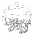
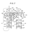
- Fig. 6 is a perspective view showing the construction apparatus as applied to practical construction, in which parts like or corresponding to those previously described with reference to Figs. 3(A), 3(B) and 5(A) to 5(G) are denoted by the same reference characters, and Fig. 7 is a schematic sectional view of assistance in explaining the function of the construction apparatus shown in Fig. 6.
- a building 110 Shown in Fig. 6 is a building 110 having the shape of a polygonal cylinder. Elevators are installed in elevator shafts formed in the internal space of the building 110 to transport construction materials including permanent columns 106 and beams 107.
- a framework 103 is constructed in a shape substantially the same in the plan as the building 110 and covered with a cover 116.
- a control room 132 is formed in a space covered with the cover 116.
- An operator operates a controller 133 including a computer and installed in the control room 132 for the automatic control of the construction work illustrated in Figs. 5(A) to 5(G).
- the permanent columns 106 provided with the beams 107 are transported from the ground to a story under construction by the elevator, not shown, installed sequentially at positions directly below the fully retracted rods 102 of the extension columns 101 by a column installing robot 109 and welded sequentially to the upper end of the permanent columns 106 of the underlying story by a column welding robot 104.
- the beams 107 of the adjacent permanent columns 106 are welded together by a beam welding robot 112.
- construction work necessary for completing the story including setting external walls 111 is carried out by using construction robots held on the traveling crane 105.
- elevating and locking mechanisms 150 are driven to elevate the framework 103 to form a working space for constructing the next upper story.
- the same construction work is repeated to construct the next upper story.
- the construction apparatus and the control room 132 are removed, and then a roof is constructed on the uppermost story of the building 110.
- the framework 103 applied to the practical construction is provided with the cover 116 consisting of a temporary roof 138 and a temporary enclosure 139 to arrest noise generated by the construction work, to prevent the influence of environmental radiowaves and electromagnetic waves on electrical communication between the controller 133 installed in the control room 132 and the construction equipment including the construction robots and to shield the control room 132 and the construction space from rain and wind.
- Providing the cover 116 with a soundproof capability and a radiowave and electromagnetic wave intercepting capability enables maintaining the working environment in a satisfactory condition and prevents the uncontrolled operation of the controller 133 and the construction robots.
- the extension columns 101, the rods 102 and the framework 103 can be used as the components of the building 110 if the extension columns 101, the rods 102 and the framework 103 are formed of members equivalent to or superior to the permanent columns 106 and the beams 107.
- the temporary roof 138 may be formed in the same construction as that of the roof of the building 110 to use the same also as the roof of the building 110.
- the guide posts 140 may be removed after completing the uppermost story of the building 110 or may be used as the permanent column of the story after removing the racks 141. If the guide posts 140 are intended for use as the permanent columns at positions for the coaxial permanent columns 106, the guide posts 140 may be such as having a length corresponding to the height of the building 110 and installed, respectively, or may be sectional guide posts extended section by section with the progress of the construction work. In latter case, the guide posts may be extended by lifting a sectional guide post by a crane or the line, inserting the sectional guide post through an opening 160 formed in the temporary roof 138 onto the upper end of the guide post previously constructed and joining the sectional guide post to the upper end of the guide post. It is also possible to extend the guide posts by previously setting the temporary roof 138 at a height sufficient to provide a space for extending the new sectional guide post, and adding the sectional guide post to the previous existing portion of the guide post within the working space 114.
- each of the guide posts 140 may be extended upward by supporting the guide post 140 at a position above the lower end thereof on a base 142 placed on an auxiliary beam 107a for shifting the guide post 140, removing a portion of the guide post 140 below the position where the guide post 140 is supported on the base 142, and joining the removed portion of the guide post 140 to the upper end of the guide post 140 as indicated by an arrow a in Fig. 7.
- each of the guide post 140 upward by extending the rods 102 of the extension columns 101 so that the lower ends of the rods 102 are brought into firm contact with the upper ends of the previously installed permanent columns 106 to transfer the weight supported by the guide posts 140 to the permanent columns 106, driving the elevating and locking mechanisms 150 to shift the guide posts 140 upward relative to the framework 103, and seating the guide posts 140 on bases 142 placed on the beam 107 of the upper story as indicated by an arrow b in Fig. 7.
- the guide posts 140 of the construction apparatus in the second embodiment support only the framework 103, the cover 116 and the construction equipments mounted on the framework 103, which are far less in weight than those supported by the plant constructed on the ground in accordance with the construction method proposed in J. P. Pat. Provisional Pub. (Kokai) No. 62-244941.
- the construction apparatus of the present invention is applicable to the construction of buildings unlimited in height and has a sufficiently high earthquake resistance.
- the construction apparatus has the following advantages.
- the framework of the construction apparatus is held securely on a completed structure of a building during the construction work for constructing the next upper structure on the completed structure and hence the framework is sufficiently resistant to earthquakes throughout the construction period because the framework is locked securely to the guide posts firmly supported on the completed structure by the elevating and locking mechanisms during the construction work for constructing the next upper structure on the completed structure.
- the working space covered with the cover enables the construction work to be carried out regardless of weather conditions.
- the construction apparatus saves labour, and enables the uninterrupted day-and-night execution of the construction work, so that the construction period is shortened remarkably and the efficiency of the construction equipments is improved.
Landscapes
- Engineering & Computer Science (AREA)
- Architecture (AREA)
- Civil Engineering (AREA)
- Structural Engineering (AREA)
- Mechanical Engineering (AREA)
- Physics & Mathematics (AREA)
- Electromagnetism (AREA)
- Conveying And Assembling Of Building Elements In Situ (AREA)
Applications Claiming Priority (7)
| Application Number | Priority Date | Filing Date | Title |
|---|---|---|---|
| JP63222048A JPH0759830B2 (ja) | 1988-09-05 | 1988-09-05 | 建設装置 |
| JP63222049A JPH0759831B2 (ja) | 1988-09-05 | 1988-09-05 | 建設装置 |
| JP222049/88 | 1988-09-05 | ||
| JP222048/88 | 1988-09-05 | ||
| JP19268089A JPH07116845B2 (ja) | 1989-07-27 | 1989-07-27 | 建設装置 |
| JP192680/89 | 1989-07-27 | ||
| EP89308941A EP0358433B1 (fr) | 1988-09-05 | 1989-09-05 | Appareil et méthode de construction |
Related Parent Applications (1)
| Application Number | Title | Priority Date | Filing Date |
|---|---|---|---|
| EP89308941.7 Division | 1989-09-05 |
Publications (2)
| Publication Number | Publication Date |
|---|---|
| EP0487516A1 true EP0487516A1 (fr) | 1992-05-27 |
| EP0487516B1 EP0487516B1 (fr) | 1995-01-18 |
Family
ID=27326651
Family Applications (2)
| Application Number | Title | Priority Date | Filing Date |
|---|---|---|---|
| EP92200399A Expired - Lifetime EP0487516B1 (fr) | 1988-09-05 | 1989-09-05 | Appareil et méthode de construction |
| EP89308941A Expired - Lifetime EP0358433B1 (fr) | 1988-09-05 | 1989-09-05 | Appareil et méthode de construction |
Family Applications After (1)
| Application Number | Title | Priority Date | Filing Date |
|---|---|---|---|
| EP89308941A Expired - Lifetime EP0358433B1 (fr) | 1988-09-05 | 1989-09-05 | Appareil et méthode de construction |
Country Status (5)
| Country | Link |
|---|---|
| US (2) | US5022199A (fr) |
| EP (2) | EP0487516B1 (fr) |
| AU (1) | AU626320B2 (fr) |
| CA (1) | CA1329633C (fr) |
| DE (2) | DE68920754T2 (fr) |
Families Citing this family (27)
| Publication number | Priority date | Publication date | Assignee | Title |
|---|---|---|---|---|
| GB2250731B (en) * | 1990-08-09 | 1994-06-01 | Mitsubishi Heavy Ind Ltd | Apparatus and method for constructing a building |
| AU651616B2 (en) * | 1990-10-08 | 1994-07-28 | Kajima Corporation | Process for constructing frame and erection |
| US5490367A (en) * | 1992-07-08 | 1996-02-13 | Lee; Wen-Yuan | Apparatus for supporting and moving vertically an erected form assembly |
| US5575591A (en) * | 1995-04-24 | 1996-11-19 | Vanderklaauw; Peter M. | Apparatus and method for a modular support and lifting system |
| US5811421A (en) * | 1995-07-31 | 1998-09-22 | Eli Lilly And Company | Naphthyl and dihydronaphthyl intermediates, compounds, compositions, and methods |
| US5980160A (en) * | 1997-02-19 | 1999-11-09 | Vanderklaauw; Peter M. | Apparatus and method for a modular lifting and shoring system |
| US6260311B1 (en) * | 1999-02-11 | 2001-07-17 | Peter Vladikovic | Concrete form suspension system and method |
| NL1015463C2 (nl) * | 2000-06-16 | 2001-12-19 | Grootint B V | Hoogbouwmethode en kolomdeel voor gebruik daarbij. |
| NO313119B1 (no) * | 2000-10-18 | 2002-08-12 | Dag Vilnes | Rammekonstruksjon for plane konstruksjoner |
| WO2006025679A1 (fr) * | 2004-08-28 | 2006-03-09 | Jiwoog Kim | Appareil de construction et procede d'installation utilisant un tel appareil |
| US7421770B1 (en) * | 2006-04-25 | 2008-09-09 | Enloe Aluminum, Inc. | Method of replacing canopy support columns |
| FR2918398A1 (fr) * | 2007-07-05 | 2009-01-09 | Bouygues Construction Sa | Procede et dispositif pour eriger une tour metallique sur un chantier |
| BRPI1008509B1 (pt) | 2009-02-09 | 2019-10-15 | 3L-Innogénie Inc. | Sistema de construção de edifícios de vários andares para construir progressivamente andares |
| CN101538897B (zh) * | 2009-04-10 | 2011-03-30 | 袁斌 | 钢筋混凝土建筑物的主体工程施工方法 |
| WO2010151539A1 (fr) | 2009-06-22 | 2010-12-29 | Barnet Liberman | Système de construction modulaire pour construire des bâtiments à plusieurs étages |
| GB2487737B (en) * | 2011-02-01 | 2013-05-01 | Teletower Com Ltd | Guardrail for an elevated working platform |
| BR112015029146A2 (pt) * | 2013-05-24 | 2017-07-25 | Air Liquide | pátio de fabricação |
| US9631379B2 (en) * | 2013-10-16 | 2017-04-25 | Neil Joseph KOOT | Building construction method and lifting device |
| DE102016205956A1 (de) * | 2016-04-08 | 2017-10-12 | Peri Gmbh | Selbstklettersystem, Selbstklettereinheit sowie Verfahren zum Umsetzen einer solchen Selbstklettereinheit an einem Betonbaukörper |
| EP3488061A4 (fr) * | 2016-09-23 | 2020-04-15 | SH Technologies Pte Ltd | Système et procédé de construction |
| US10753080B1 (en) | 2019-03-29 | 2020-08-25 | Big Time Investment, Llc | Method of constructing a building, and a building construction system therefor |
| US20210156156A1 (en) * | 2019-11-27 | 2021-05-27 | OM Engineering Pty Ltd | Independent self-climbing form system for building vertical structures |
| CN112302185A (zh) * | 2020-10-20 | 2021-02-02 | 智远谋 | 一种安全性高的网架顶升用支撑架 |
| CN112758855B (zh) * | 2020-12-24 | 2022-06-28 | 河北永基电力器材有限公司 | 通信设备安装用的固定组件 |
| CN113875468B (zh) * | 2021-11-22 | 2023-04-07 | 浙江德利遮阳材料有限公司 | 农作物种植用双层遮阳网拱棚的施工方法 |
| CN116201160B (zh) * | 2023-01-06 | 2023-08-15 | 华锦建设集团股份有限公司 | 房屋建筑桩基结构及施工方法 |
| EP4575140A1 (fr) * | 2023-12-19 | 2025-06-25 | Scaffco Holding A/S | Système d'échafaudage de toit temporaire |
Citations (2)
| Publication number | Priority date | Publication date | Assignee | Title |
|---|---|---|---|---|
| FR862806A (fr) * | 1940-01-09 | 1941-03-17 | Perfectionnements à un procédé pour la construction de maisons | |
| FR2214019A1 (fr) * | 1973-01-16 | 1974-08-09 | Six Jean |
Family Cites Families (12)
| Publication number | Priority date | Publication date | Assignee | Title |
|---|---|---|---|---|
| US122937A (en) * | 1872-01-23 | Improvement in constructing buildings | ||
| DE929089C (de) * | 1949-11-01 | 1955-06-20 | Wilhelm Dr-Ing Ludowici | Verfahren zur Errichtung von Gebaeuden |
| US2739850A (en) * | 1952-11-28 | 1956-03-27 | Thomas H Hollingsworth | Telescopic tower jack |
| US3017968A (en) * | 1957-01-14 | 1962-01-23 | Mcmahon William Horice | Scaffold |
| US4032501A (en) * | 1975-07-11 | 1977-06-28 | The Firestone Tire & Rubber Company | Dry-blendable solution rubber powders and process |
| DE2917972A1 (de) * | 1979-05-04 | 1980-11-13 | Gerd Drespa | Allwetter-baufortschritt-system |
| US4374786A (en) * | 1981-08-05 | 1983-02-22 | Glitsch, Inc. | Unitized scrubber tower |
| US4528793A (en) * | 1982-12-17 | 1985-07-16 | Johnson Delp W | Method of constructing precast concrete building with ductile concrete frame |
| US4557099A (en) * | 1983-08-01 | 1985-12-10 | Johnson Delp W | Method of constructing foldable concrete slab buildings with access slots thru ceiling slabs for installing hingeable connectors |
| LU86272A1 (fr) * | 1986-01-28 | 1987-09-03 | Wurth Paul Sa | Installation automatisee pour briqueter la paroi interieure d'une enceint |
| JPH0733688B2 (ja) * | 1986-04-16 | 1995-04-12 | 学校法人早稲田大学 | プツシユアツプ工法 |
| US4980999A (en) * | 1988-07-27 | 1991-01-01 | Terenzoni Robert S | System for raising a roof |
-
1989
- 1989-09-05 DE DE68920754T patent/DE68920754T2/de not_active Expired - Fee Related
- 1989-09-05 CA CA000610263A patent/CA1329633C/fr not_active Expired - Fee Related
- 1989-09-05 DE DE68912037T patent/DE68912037T2/de not_active Expired - Fee Related
- 1989-09-05 AU AU41088/89A patent/AU626320B2/en not_active Ceased
- 1989-09-05 EP EP92200399A patent/EP0487516B1/fr not_active Expired - Lifetime
- 1989-09-05 US US07/402,811 patent/US5022199A/en not_active Expired - Lifetime
- 1989-09-05 EP EP89308941A patent/EP0358433B1/fr not_active Expired - Lifetime
-
1991
- 1991-03-15 US US07/668,854 patent/US5088263A/en not_active Expired - Fee Related
Patent Citations (2)
| Publication number | Priority date | Publication date | Assignee | Title |
|---|---|---|---|---|
| FR862806A (fr) * | 1940-01-09 | 1941-03-17 | Perfectionnements à un procédé pour la construction de maisons | |
| FR2214019A1 (fr) * | 1973-01-16 | 1974-08-09 | Six Jean |
Also Published As
| Publication number | Publication date |
|---|---|
| DE68912037T2 (de) | 1994-07-28 |
| EP0358433A2 (fr) | 1990-03-14 |
| US5022199A (en) | 1991-06-11 |
| AU626320B2 (en) | 1992-07-30 |
| US5088263A (en) | 1992-02-18 |
| DE68920754T2 (de) | 1995-09-07 |
| EP0487516B1 (fr) | 1995-01-18 |
| EP0358433A3 (en) | 1990-07-18 |
| DE68912037D1 (de) | 1994-02-17 |
| EP0358433B1 (fr) | 1994-01-05 |
| AU4108889A (en) | 1990-03-08 |
| CA1329633C (fr) | 1994-05-17 |
| DE68920754D1 (de) | 1995-03-02 |
Similar Documents
| Publication | Publication Date | Title |
|---|---|---|
| EP0487516B1 (fr) | Appareil et méthode de construction | |
| EP0654571B1 (fr) | Procede d'assemblage de modules de zone d'une construction a structure en acier | |
| KR19990072014A (ko) | 위에서지면으로건축물을건설하는리프트업공법 | |
| US5327690A (en) | Erection workbench for constructing a frame | |
| JPH0483060A (ja) | 建築物構造 | |
| JPH05133016A (ja) | 周辺保持自昇式建築工法 | |
| JPH0270845A (ja) | 建設装置 | |
| JP3066460B2 (ja) | 鉄塔の構築方法 | |
| JP2957323B2 (ja) | リフトアップ式建築工法 | |
| JPH04254665A (ja) | ジャッキアップ式のビル構築装置及びその構築工法 | |
| JP3225455B2 (ja) | 建屋の構築方法 | |
| JPH07116845B2 (ja) | 建設装置 | |
| JP2761528B2 (ja) | 構造物の構築方法 | |
| JPH0447072A (ja) | 高層建築物の建設方法及びその装置 | |
| JPH0518132A (ja) | タワー式立体駐車場等鉄骨構造物のジヤツキアツプ式建設工法 | |
| JPS62244942A (ja) | プツシユアツプ方法および装置 | |
| JPH04231530A (ja) | 高層建物の躯体施工装置 | |
| JPH11131811A (ja) | 建物の建築方法 | |
| JPH0270844A (ja) | 建設装置 | |
| JPH0781323B2 (ja) | 建築物の構築工法 | |
| JPH0540492U (ja) | 自動昇降型作業足場 | |
| JPH04118438A (ja) | 建築物の施工方法およびその装置 | |
| JPH0390769A (ja) | 建設装置 | |
| JPH062435A (ja) | 天井クレーン架構を用いた鉄骨架構の構築方法 | |
| JPH04155034A (ja) | 小規模建築物の施工方法 |
Legal Events
| Date | Code | Title | Description |
|---|---|---|---|
| PUAI | Public reference made under article 153(3) epc to a published international application that has entered the european phase |
Free format text: ORIGINAL CODE: 0009012 |
|
| 17P | Request for examination filed |
Effective date: 19920228 |
|
| AC | Divisional application: reference to earlier application |
Ref document number: 358433 Country of ref document: EP |
|
| AK | Designated contracting states |
Kind code of ref document: A1 Designated state(s): DE FR GB IT NL SE |
|
| 17Q | First examination report despatched |
Effective date: 19931227 |
|
| GRAA | (expected) grant |
Free format text: ORIGINAL CODE: 0009210 |
|
| AC | Divisional application: reference to earlier application |
Ref document number: 358433 Country of ref document: EP |
|
| AK | Designated contracting states |
Kind code of ref document: B1 Designated state(s): DE FR GB IT NL SE |
|
| REF | Corresponds to: |
Ref document number: 68920754 Country of ref document: DE Date of ref document: 19950302 |
|
| ET | Fr: translation filed | ||
| ITF | It: translation for a ep patent filed | ||
| PLBE | No opposition filed within time limit |
Free format text: ORIGINAL CODE: 0009261 |
|
| STAA | Information on the status of an ep patent application or granted ep patent |
Free format text: STATUS: NO OPPOSITION FILED WITHIN TIME LIMIT |
|
| 26N | No opposition filed | ||
| K1C1 | Correction of patent application (title page) published |
Effective date: 19920527 |
|
| PGFP | Annual fee paid to national office [announced via postgrant information from national office to epo] |
Ref country code: GB Payment date: 19990901 Year of fee payment: 11 |
|
| PGFP | Annual fee paid to national office [announced via postgrant information from national office to epo] |
Ref country code: DE Payment date: 19990906 Year of fee payment: 11 |
|
| PGFP | Annual fee paid to national office [announced via postgrant information from national office to epo] |
Ref country code: SE Payment date: 19990907 Year of fee payment: 11 |
|
| PGFP | Annual fee paid to national office [announced via postgrant information from national office to epo] |
Ref country code: FR Payment date: 19990909 Year of fee payment: 11 |
|
| PGFP | Annual fee paid to national office [announced via postgrant information from national office to epo] |
Ref country code: NL Payment date: 19990930 Year of fee payment: 11 |
|
| PG25 | Lapsed in a contracting state [announced via postgrant information from national office to epo] |
Ref country code: GB Free format text: LAPSE BECAUSE OF NON-PAYMENT OF DUE FEES Effective date: 20000905 |
|
| PG25 | Lapsed in a contracting state [announced via postgrant information from national office to epo] |
Ref country code: SE Free format text: THE PATENT HAS BEEN ANNULLED BY A DECISION OF A NATIONAL AUTHORITY Effective date: 20000929 |
|
| PG25 | Lapsed in a contracting state [announced via postgrant information from national office to epo] |
Ref country code: NL Free format text: LAPSE BECAUSE OF NON-PAYMENT OF DUE FEES Effective date: 20010401 |
|
| GBPC | Gb: european patent ceased through non-payment of renewal fee |
Effective date: 20000905 |
|
| EUG | Se: european patent has lapsed |
Ref document number: 92200399.1 |
|
| PG25 | Lapsed in a contracting state [announced via postgrant information from national office to epo] |
Ref country code: FR Free format text: LAPSE BECAUSE OF NON-PAYMENT OF DUE FEES Effective date: 20010531 |
|
| NLV4 | Nl: lapsed or anulled due to non-payment of the annual fee |
Effective date: 20010401 |
|
| PG25 | Lapsed in a contracting state [announced via postgrant information from national office to epo] |
Ref country code: DE Free format text: LAPSE BECAUSE OF NON-PAYMENT OF DUE FEES Effective date: 20010601 |
|
| REG | Reference to a national code |
Ref country code: FR Ref legal event code: ST |
|
| PG25 | Lapsed in a contracting state [announced via postgrant information from national office to epo] |
Ref country code: IT Free format text: LAPSE BECAUSE OF NON-PAYMENT OF DUE FEES;WARNING: LAPSES OF ITALIAN PATENTS WITH EFFECTIVE DATE BEFORE 2007 MAY HAVE OCCURRED AT ANY TIME BEFORE 2007. THE CORRECT EFFECTIVE DATE MAY BE DIFFERENT FROM THE ONE RECORDED. Effective date: 20050905 |