EP0572218A2 - Schabloneplatte zum Drucken auf Papier - Google Patents
Schabloneplatte zum Drucken auf Papier Download PDFInfo
- Publication number
- EP0572218A2 EP0572218A2 EP19930304046 EP93304046A EP0572218A2 EP 0572218 A2 EP0572218 A2 EP 0572218A2 EP 19930304046 EP19930304046 EP 19930304046 EP 93304046 A EP93304046 A EP 93304046A EP 0572218 A2 EP0572218 A2 EP 0572218A2
- Authority
- EP
- European Patent Office
- Prior art keywords
- film
- stencil
- paper sheet
- adhered
- heat sensitive
- Prior art date
- Legal status (The legal status is an assumption and is not a legal conclusion. Google has not performed a legal analysis and makes no representation as to the accuracy of the status listed.)
- Withdrawn
Links
Images





Classifications
-
- B—PERFORMING OPERATIONS; TRANSPORTING
- B41—PRINTING; LINING MACHINES; TYPEWRITERS; STAMPS
- B41N—PRINTING PLATES OR FOILS; MATERIALS FOR SURFACES USED IN PRINTING MACHINES FOR PRINTING, INKING, DAMPING, OR THE LIKE; PREPARING SUCH SURFACES FOR USE AND CONSERVING THEM
- B41N1/00—Printing plates or foils; Materials therefor
- B41N1/24—Stencils; Stencil materials; Carriers therefor
- B41N1/248—Mechanical details, e.g. fixation holes, reinforcement or guiding means; Perforation lines; Ink holding means; Visually or otherwise detectable marking means; Stencil units
Definitions
- This invention relates to a stencil plate.
- Heat sensitive stencil paper sheets which can be perforated by irradiation of infrared rays or by means of a thermal head are conventionally known.
- a typical one of the conventional heat sensitive stencil paper sheets includes a heat sensitive film and a porous thin paper sheet adhered to the heat sensitive film using a bonding agent.
- a stencil paper printing apparatus using a single cylinder, such as shown in Fig. 8, is known for using this described conventional heat sensitive stencil paper sheet.
- the stencil paper printing apparatus includes a plate cylinder 62 which has a perforated photosensitive stencil paper sheet 64 wound on an outer periphery thereof with its porous support member positioned on the inner side. Ink is supplied from the inside toward the outer periphery of the plate cylinder 62.
- a press roller 66 is contacted under pressure with the plate cylinder 62 with printing paper 68 interposed therebetween while the plate cylinder 62 is driven to rotate to effect printing on the printing paper 68.
- FIG. 9 Shown in Fig. 9 is a second type of conventional stencil paper printing apparatus.
- the stencil paper printing apparatus uses a heat sensitive stencil paper sheet 70 formed of a heat sensitive film.
- a porous support member 84 is adhered to the heat sensitive film and has a frame member 72 provided along a periphery of the porous support member 84.
- the porous support member 84 serves as an ink applying portion and is enclosed by the frame member 72 and an ink-impermeable cover sheet 74.
- the stencil paper printing apparatus includes a pressing member 78, a receiving table 80 disposed in an opposing relationship to the pressing member 78, and a holding member 82 disposed at a peripheral portion of the face of the pressing member 78, opposed to the receiving table 80, for holding the heat sensitive stencil paper sheet 70 thereon.
- Ink is applied to the porous support member 84, surrounded by the frame member 72, of the perforated heat sensitive stencil paper sheet 70. Then the porous support member 84 and the frame member 72, attached on one side to heat sensitive stencil paper sheet 70, are covered with the cover sheet 74 on the opposite side prior to mounting on the pressing member 78.
- the heat sensitive stencil paper sheet 70 is held on the pressing member 78 by the holding member 82 and the holding member 78 is moved toward, and pressed against, the receiving table 80 with printing paper 86 interposed therebetween to effect printing on the printing paper 86.
- a stencil paper printing apparatus of the cylinder type described above has a large size. Since it can be used to print large stencils, it has a comparatively high running cost when required to print comparatively small amounts of material, i.e. only a small portion of the stencil has printing perforations.
- the pressing type stencil paper printing apparatus has a comparatively small size.
- it has a disadvantage in that the user must apply the ink. Therefore, the hands or the clothes of the user may be soiled when the ink is applied and, since the ink is not readily applied with a uniform thickness, a regular print may not be obtained.
- the stencil plate 50 includes successive layers of a heat sensitive stencil paper sheet 56 formed of a thermoplastic film 52 and a porous support member 54 adhered to the thermoplastic film 52, a non-woven fabric 58 disposed on the heat sensitive stencil paper sheet 56 adjacent to the porous support member 54 and impregnated with ink, and an ink-impermeable film 59 serving as a base member.
- a perforation image is formed on the stencil plate 50 by heat melting the thermoplastic film 52 of the heat sensitive stencil paper sheet 56 by means of a stenciling apparatus which employs, for example, a thermal head. Such formation of a perforation image will be hereinafter referred to as stenciling.
- the stencil plate 50 thus stenciled, is mounted onto a stamping member provided with a grip and the stamping member is pressed against printing paper to effect stencil paper printing.
- the stencil plate 10 includes, as principal components thereof, a heat sensitive stencil paper sheet 12, a separator 14, a non-woven fabric 16 impregnated with ink, a frame member 18 disposed so as to surround the non-woven fabric 16, and an ink-impermeable film 20 serving as a base member.
- the heat sensitive stencil paper sheet 12 includes, as shown in Fig. 13, a thermoplastic film 22, a bonding agent layer 24, and a porous support member 26.
- the thermoplastic film 22 is formed of a polyethylene terephthalate film (hereinafter referred to as PET film) approximately 2 ⁇ m thick, but may alternatively be formed of a film of, for example, polypropylene or copolymer of vinylidene chloride-vinyl chloride.
- PET film is 1 to 4 ⁇ m thick.
- a thickness, of the PET film, of less than 1 ⁇ m results in high production costs and does not provide sufficient strength. Accordingly, the PET film of such thickness is not suitable for practical use.
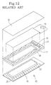
- the heat sensitive stencil paper sheet 12 structured as described above adheres, at four sides thereof, to the frame member 18 by means of a bonding agent layer 28 as shown in Fig. 12.
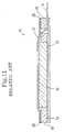
- An opening 17 having a size corresponding to the size of the non-woven fabric 16 is formed at a central portion of the frame member 18 as shown in Figs. 11 and 12.
- a small hole 19 for removing the separator 14 therethrough is formed at a right portion of the frame member 18 (as shown in Figs. 11 and 12).
- the frame member 18 is made of a material which is not attacked by oil ink, such as, for example, vinyl chloride, polypropylene, polyethylene, polyacetal or polyethylene terephthalate.
- the non-woven fabric 16 is impregnated, in a saturated condition, with the oil ink so that when a pressure is applied to it, the ink impregnated therein oozes from the non-woven fabric 16.
- the non-woven fabric 16 is made of a synthetic fiber of polyethylene, polypropylene or polyethylene terephthalate.
- the thickness of the non-woven fabric 16 is set greater than one half but smaller than three times the thickness of the frame member 18.
- the non-woven fabric 16 is set so that it is compressed, upon stenciling, by the pressing force of the thermal head so that it presents a thickness equal to that of the frame member 18.
- the separator 14 is disposed between the heat sensitive stencil paper sheet 12 and the non-woven fabric 16. A portion thereof, shown in Figure 12 as a right portion, extends through the small, oblong hole 19 formed in the frame member 18 and further between the frame member 18 and the film 20 to project beyond the end of the stencil plate 10.
- the size of the separator 14 is set to be greater than the size of the non-woven fabric 16. More particularly, referring to Fig. 12, the area the separator 14 covers beyond the non-woven fabric 16 is defined by a chain line shown on the frame member 18.
- the separator 14 may be formed of mold separating paper produced by applying a silicon film to wood-free or glassine paper or of a resin film of polyethylene terephthalate or ethylene tetrafluoride (trade name: Teflon).
- Teflon polyethylene terephthalate or ethylene tetrafluoride
- a silicon film is formed not only on the face of the mold separating paper contacting the non-woven fabric 16 but also on the other face as well.
- the ink may spread to the heat sensitive stencil paper sheet 12 side of the separator 14 and there is the possibility that, when perforations are formed, ink may ooze from the perforation portions.
- the film 20 is formed of a film of a resin which is not attacked by oil ink such as vinyl chloride, polypropylene, polyethylene or polyethylene terephthalate.
- the stencil plate 10 described above is stenciled using a stenciling apparatus (not shown).
- a stenciling apparatus mirror-image prints the face of the thermoplastic film 22 of the heat sensitive stencil paper sheet 12 by means of a thermal head to heat the thermoplastic film 22 to melt and perforate same.
- the thermal head is pressed against the stencil plate 10 under a predetermined pressing force and, in this instance, since the separator 14 is disposed between the heat sensitive stencil paper sheet 12 and the non-woven fabric 16, even if the thermoplastic film 22 of the heat sensitive stencil paper sheet 12 is perforated, ink does not ooze from the perforation portions.
- the stencil plate 10, stenciled in this manner, is mounted onto a stamping member 34 (shown in Fig. 14).
- the stamping member 34 consists of a handle portion 36, a cushion layer 38 and an adhesive layer 40.
- the stencil plate 10 is mounted onto the stamping member 34 by adhering the film 20 side of the stencil plate 10 to the adhesive layer 40 of the stamping member 34. Thereafter, the separator 14 (shown in Fig. 12) is pulled from the stencil plate 10.
- the stamping member 34 can then be pressed against a printing paper 42, whereupon the non-woven fabric 16 is compressed so that ink oozes from the perforated portions of the printing face of the stencil plate 10 and is transferred to the printing paper 42.
- the conventional stencil plate 10 has several problems, such as the formation of irregular perforations caused by slippage between the separator 14, having a low wettability, and the heat sensitive stencil paper sheet 12 upon formation of an image on the heat sensitive stencil paper sheet 12, soiling of the thermal head of the perforating stenciling apparatus caused by ink oozing from an end face of the separator 14 to the heat sensitive stencil paper sheet 12 side, and the production of wrinkles in the heat sensitive stencil paper sheet 12 upon stamping caused by the admission of air between the non-woven fabric 16 and the heat sensitive stencil paper sheet 12 upon removal of the separator 14 after formation of an image.
- a stencil plate which comprises a heat sensitive stencil paper sheet formed of a thermoplastic film and a porous support member adhered to the thermoplastic film, an impregnated member disposed on the heat sensitive stencil paper sheet adjacent to the porous support member and impregnated with ink, an ink-permeable base member on which the heat sensitive stencil paper sheet and the impregnated member are layered successively, and a thin film peelably provided on a surface of the heat sensitive stencil paper sheet and having a heat resisting property higher than the thermoplastic film.
- the high temperature heat resisting thin film is not perforated by a stenciling apparatus employing a thermal head. Only the heat sensitive stencil paper sheet is perforated to stencil the stencil plate.
- the stenciled plate is mounted onto a stamping member, the high temperature heat resisting thin film is peeled from the heat sensitive stencil paper sheet and thereafter the stamping member is pressed against printing paper, then the ink in the impregnated member is forced from the perforation portions of the heat sensitive stencil paper sheet to thereby effect stencil paper printing.
- the heat sensitive stencil paper sheet since the thin film, having a heat resisting property higher than that of the thermoplastic film of the heat sensitive stencil paper sheet, is peelably provided on the surface of the heat sensitive stencil paper sheet, the heat sensitive stencil paper sheet does not suffer from irregular formation of perforations, no ink sticks to a thermal head for stenciling the stencil plate, and, upon stamping, no wrinkles are produced on the heat sensitive stencil paper sheet.
- a stencil plate which comprises a thin film having a high temperature heat resisting property and peelably provided on a surface of a heat sensitive stencil paper sheet and a peelable member adhered to at least part of the thin film for peeling the thin film from the heat sensitive stencil paper sheet.
- the stencil plate after stenciling is mounted onto a stamping member, and the thin film is peeled from the heat sensitive stencil paper sheet making use of the peelable member.
- the thin film having a higher temperature heat resisting property than the heat sensitive stencil paper sheet, that will be peeled away after stenciling
- the thin film which is not very strong by itself, is stiffened by the peelable member, which facilitates handling of the thin film and, consequently, no ink will stick to the hand or clothes of the user.
- the stencil plate includes, as principal components thereof, a surface film 60, a heat sensitive stencil paper sheet 12, a non-woven fabric 16 impregnated with ink, a frame member 18 disposed so as to surround the non-woven fabric 16, and an ink-impermeable film 20, serving as a base member.
- the heat sensitive stencil paper sheet 12 which has the same structure as that of the prior art, is adhered, at the four sides thereof, to the frame member 18 by means of a bonding agent layer 28 as shown in Fig. 2.
- the frame member 18 has an opening 17 formed at a central portion thereof. Opening 17 has a size corresponding to the size of the non-woven fabric 16.
- the non-woven fabric 16 is impregnated, in a saturated condition, with oil ink and is fixed to the film 20 to that, when a pressure is applied to the non-woven fabric, the ink impregnated therein in oozes from it.
- the film 20 is adhered to the rear face of the frame member 28 by means of a bonding agent layer 32 indicated by slanting lines in Fig. 2.
- the surface film 60 adheres to the heat sensitive stencil paper sheet 12 in a closely contacting relationship so that no air layer is formed between them.
- silicon grease is used as the bonding agent for adhering surface film 60 and the heat sensitive stencil paper sheet 12.
- the bonding agent must have the characteristic that it is strong against a peeling force acting in a direction of 0 degree, that is, parallel to the plane defined by frame member 18, in order to prevent a lateral displacement between the heat sensitive stencil paper sheet 12 and the surface film 60 during perforation when a thermal head is pressed against the surface film 60, but is weak against a peeling force acting in the direction between 90 and 180 degrees to the plane of the frame member 18, that is between a right angle and a directly opposite direction, so that the surface film 60 may be peeled readily from the heat sensitive stencil paper sheet 12 after formation of an image on the heat sensitive stencil paper sheet 12.
- the surface film 60 has a high temperature heat resisting property that is higher than that of the thermoplastic film 22 of the heat sensitive stencil paper sheet 12 and preferably has a high temperature heat resisting temperature that is at least higher by 50°C or more than that of the heat sensitive stencil paper sheet 12.
- the surface film 60 and the thermoplastic film 22 may be, for example, a combination of, as the thermoplastic film 22, a PET film of 1 to 2 ⁇ m thick having a high temperature heat resisting temperature of approximately 120 °C during continuous heating and, as the surface film 60, a thin film of a metal of 3 ⁇ m or less thickness having a heat resisting temperature equal to or higher than 180 °C during in continuous heating, such as titanium, aluminum or silver, or a film of polyether ether ketone or polyether sulfone.
- a PET film 2 ⁇ m thick is employed as the thermoplastic film 22 while an aramid film (para-aromatic polyamide: APA) 3 ⁇ m thick is employed as the surface film 60.
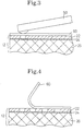
- Heat is applied to the stencil plate 10 from above the surface film 60, by means of a thermal head 50 of a stenciling apparatus as shown in Fig. 3. Because of the difference between the heat resisting temperatures of the surface film 60 and the thermoplastic film 22 of the heat sensitive stencil paper sheet 12 during continuous heating, the surface film 60 is not melted by the heat from the thermal head 50 and only the thermoplastic film 22 is melted so that a perforation image is formed thereon.
- the stencil plate 10 will be mounted, such as shown in Fig. 14, onto the stamping member 34 by adhering the film 20 face side thereof to the adhesive layer 40 of the stamping member 34, and then the stamping member 34 will be pressed against printing paper 42. Consequently, the non-woven fabric 16 is compressed so that the ink impregnated in it oozes from the perforation portions of the printing face of the stencil plate 10 thereby transferring the ink to the printing paper 42.
- the stencil plate 10 is advantageous in that it does not cause formation of irregular perforations since the surface film 60 and the heat sensitive stencil paper sheet 12 are held in close contact with each other, it does not cause sticking of ink to the thermal head 50 since the surface film 60 is interposed between the heat sensitive stencil paper sheet 12 and the thermal head 50, and it does not produce wrinkles on the heat sensitive stencil paper sheet 12 upon stamping since no air is admitted between the heat sensitive stencil paper sheet 12 and the non-woven fabric 16.
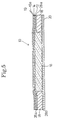
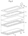
- Figs. 5 and 6 show a stencil plate 10 in a second preferred embodiment according to the invention.
- the stencil plate 10 includes a peelable member 19, a surface film 14, a heat sensitive stencil paper sheet 12, a non-woven fabric 16 impregnated with ink, a frame member 18 disposed so as to surround the non-woven fabric 16, and an ink-impermeable film 20 serving as a base member.
- the elements are layered successively from top to bottom in the order described.
- the surface film 14 is formed of a high temperature heat resisting thin film and is adhered to the heat sensitive stencil paper sheet 12 by means of a bonding agent in such a closely contacting condition that no air layer is formed between them.
- the bonding agent is required to have the characteristic that it is strong against a peeling force acting in direction parallel to the plane of the heat sensitive stencil paper sheet 12, that is a direction of 0 degree, but is weak against a peeling force acting in the direction between 90 and 180 degrees relative to the plane, that is at a right angle up to a directly opposite direction.
- silicon grease is employed as the bonding agent.
- the surface film 14 is formed of a thin film of no more than 4 ⁇ m thickness having a heat resistance temperature equal to or higher than 180 °C, such as, for example, a thin film of a metal, such as titanium, aluminum, silver or gold or a thin film of polyether ether ketone or polyether sulfone.
- a metal such as titanium, aluminum, silver or gold
- a thin film of polyether ether ketone or polyether sulfone such as polyether ether ketone or polyether sulfone.
- an aramid film para aromatic polyamide; APA
- the peelable member 19 includes a base member formed of paper or a plastic film and an adhesive layer (not shown) of the acrylic type or the silicon type applied to the base member.
- the peelable member 19 is adhered to the surface film 14 by the action of the adhesive layer. While it is possible to apply the peelable member 19 in advance to the surface film 14, preferably the peelable film 19 is applied to the surface film 14 at the last stage of production of the stencil plate 10.
- the stencil plate 10 When the stencil plate 10, described above, is stenciled by a known stenciling apparatus, for example, a thermal head (not shown), since the difference between the continuous duty temperatures of the surface film 14 and the thermoplastic film of the heat sensitive stencil paper sheet 12 is great, the surface film 14 is not melted by heat from the thermal head but the thermoplastic film is melted by the heat so that a perforated image is formed thereon.
- a thermal head since the difference between the continuous duty temperatures of the surface film 14 and the thermoplastic film of the heat sensitive stencil paper sheet 12 is great, the surface film 14 is not melted by heat from the thermal head but the thermoplastic film is melted by the heat so that a perforated image is formed thereon.
- the stenciled plate 10 can be fixed to a stamping member 34, such as shown in Fig. 14, which includes a handle portion 36, a cushion layer 38 and an adhesive layer 40 and is used to print on printing paper 42.
- a stamping member 34 such as shown in Fig. 14, which includes a handle portion 36, a cushion layer 38 and an adhesive layer 40 and is used to print on printing paper 42.
- the stencil plate 10 in the present embodiment has the surface film 14, in the form of a thin film having a high temperature heat resisting property, that is peelably provided on the surface of the heat sensitive stencil paper sheet 12.
- the stencil plate 10 is stenciled by means of a thermal head or the like serving as stenciling means, ink does not ooze from the perforated portions of the heat sensitive stencil paper sheet 12.
- the heat sensitive stencil paper sheet 12 which is not very stiff by itself, is stiffened by the peelable member 19 to facilitate handling of the heat sensitive stencil paper sheet 12 and, consequently, prevents ink from sticking to the hands or clothes of the user.
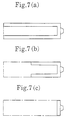
- the peelable member 19 is formed as a member having a frame-like configuration so that it surrounds the printing face of the heat sensitive stencil paper sheet 12, it may otherwise be formed as a member having any of the configurations shown in Figs. 7(a) to 7(c) if it facilitates peeling of the surface film 14.
Landscapes
- Engineering & Computer Science (AREA)
- Mechanical Engineering (AREA)
- Printing Plates And Materials Therefor (AREA)
Applications Claiming Priority (4)
| Application Number | Priority Date | Filing Date | Title |
|---|---|---|---|
| JP13506392A JPH05330264A (ja) | 1992-05-27 | 1992-05-27 | 孔版印刷用原板 |
| JP3534092U JP2582732Y2 (ja) | 1992-05-27 | 1992-05-27 | 印刷用原板 |
| JP135063/92 | 1992-05-27 | ||
| JP35340/92U | 1992-05-27 |
Publications (2)
| Publication Number | Publication Date |
|---|---|
| EP0572218A2 true EP0572218A2 (de) | 1993-12-01 |
| EP0572218A3 EP0572218A3 (en) | 1994-09-14 |
Family
ID=26374321
Family Applications (1)
| Application Number | Title | Priority Date | Filing Date |
|---|---|---|---|
| EP9393304046A Withdrawn EP0572218A3 (en) | 1992-05-27 | 1993-05-25 | Plate for stencil paper printing |
Country Status (2)
| Country | Link |
|---|---|
| US (1) | US5303647A (de) |
| EP (1) | EP0572218A3 (de) |
Cited By (1)
| Publication number | Priority date | Publication date | Assignee | Title |
|---|---|---|---|---|
| WO2011091457A1 (de) | 2010-01-27 | 2011-08-04 | Colop Stempelerzeugung Skopek Gesellschaft M.B.H. & Co. Kg. | Farbspeichereinheit für einen handstempel |
Families Citing this family (16)
| Publication number | Priority date | Publication date | Assignee | Title |
|---|---|---|---|---|
| JP3018836B2 (ja) * | 1993-07-15 | 2000-03-13 | ブラザー工業株式会社 | 孔版印刷用原版 |
| DE69402381T2 (de) * | 1993-08-17 | 1997-11-20 | Diafoil Hoechst Co Ltd | Polyesterfilm für höchst wärmeempfindliches Originalblatt für Schablonendruckverfahren |
| JP3085071B2 (ja) * | 1993-12-24 | 2000-09-04 | ブラザー工業株式会社 | スタンプユニット用加熱印字装置 |
| US6113346A (en) | 1996-07-31 | 2000-09-05 | Agfa Corporation | Method for loading and unloading a supply of plates in an automated plate handler |
| US5655452A (en) * | 1996-08-07 | 1997-08-12 | Agfa Division, Bayer Corp. | Method and apparatus for an automated plate handler with slip sheet removal mechanism |
| GB2333997B (en) | 1998-02-06 | 2002-07-17 | Autotype Internat Ltd | Screen printing stencil production |
| JP3405259B2 (ja) * | 1999-03-17 | 2003-05-12 | カシオ計算機株式会社 | 突起電極の形成方法及び突起電極を備えたフィルム基板の製造方法並びに突起電極を備えた半導体装置の製造方法 |
| KR100689166B1 (ko) * | 1999-07-06 | 2007-03-08 | 부라더 고교 가부시키가이샤 | 스탬프용 도장 부재 및 이를 이용한 스탬프 유닛 |
| US6681691B2 (en) | 2000-03-02 | 2004-01-27 | Autotype International Limited | Screen printing stencil production |
| US6892637B2 (en) * | 2003-02-28 | 2005-05-17 | Craig J. Petersen | Self-inking stamp with ink cartridge barrier |
| US6827014B1 (en) * | 2003-05-21 | 2004-12-07 | F. W. Marshall, Inc. | System for mounting, using and storing rubber stamps |
| US7506582B2 (en) * | 2004-01-30 | 2009-03-24 | Petersen Craig J | Hand stamp with adhesively held ink cartridge |
| US7073437B2 (en) * | 2004-01-30 | 2006-07-11 | Petersen Craig J | Hand stamp with adhesively held ink cartridge |
| US8557758B2 (en) | 2005-06-07 | 2013-10-15 | S.C. Johnson & Son, Inc. | Devices for applying a colorant to a surface |
| US8061269B2 (en) | 2008-05-14 | 2011-11-22 | S.C. Johnson & Son, Inc. | Multilayer stencils for applying a design to a surface |
| JP7203489B2 (ja) * | 2017-09-19 | 2023-01-13 | 株式会社ミマキエンジニアリング | 印刷方法、及びスクリーン印刷版の製造方法 |
Family Cites Families (10)
| Publication number | Priority date | Publication date | Assignee | Title |
|---|---|---|---|---|
| US3799053A (en) * | 1972-07-13 | 1974-03-26 | Marsh Stencil Machine Co | Hand printer |
| GB1579459A (en) * | 1976-08-26 | 1980-11-19 | Riso Kagaku Corp | Printing device for stencils |
| GB2029039B (en) * | 1978-08-24 | 1982-10-27 | Letraset International Ltd | Photosensitive materials |
| US4476976A (en) * | 1983-04-19 | 1984-10-16 | Marvin Elkins | Stencilling device |
| JPS61116595A (ja) * | 1984-11-12 | 1986-06-04 | Riso Kagaku Corp | 感熱孔版印刷用原紙 |
| JPS61125897A (ja) * | 1984-11-22 | 1986-06-13 | Ricoh Co Ltd | 感熱孔版原紙 |
| JPS62238792A (ja) * | 1986-04-09 | 1987-10-19 | Asia Genshi Kk | 感熱性孔版原紙 |
| JPH0755577B2 (ja) * | 1986-07-09 | 1995-06-14 | 理想科学工業株式会社 | 手押し用スタンプホ−ルダ |
| JPH02169298A (ja) * | 1988-12-23 | 1990-06-29 | Asahi Chem Ind Co Ltd | 感熱性孔版用フィルム及び原紙 |
| JP3038882B2 (ja) * | 1990-10-30 | 2000-05-08 | ブラザー工業株式会社 | 感熱性孔版原紙 |
-
1993
- 1993-04-23 US US08/051,561 patent/US5303647A/en not_active Expired - Fee Related
- 1993-05-25 EP EP9393304046A patent/EP0572218A3/en not_active Withdrawn
Cited By (6)
| Publication number | Priority date | Publication date | Assignee | Title |
|---|---|---|---|---|
| WO2011091457A1 (de) | 2010-01-27 | 2011-08-04 | Colop Stempelerzeugung Skopek Gesellschaft M.B.H. & Co. Kg. | Farbspeichereinheit für einen handstempel |
| CN102725146A (zh) * | 2010-01-27 | 2012-10-10 | 克罗普压印器制造斯科皮克两合公司 | 用于手动印章的印泥存储单元 |
| US8789463B2 (en) | 2010-01-27 | 2014-07-29 | Colop Stempelerzeugung Skopek Gesellschaft m.b.H. & Co. KG | Ink storing unit for a hand-operated stamp |
| EP2528743B1 (de) * | 2010-01-27 | 2014-11-19 | Colop Stempelerzeugung Skopek Gesellschaft M.B.H. & Co. Kg. | Farbspeichereinheit für einen handstempel |
| CN102725146B (zh) * | 2010-01-27 | 2014-12-31 | 克罗普压印器制造斯科皮克两合公司 | 用于手动印章的印泥存储单元 |
| US8925454B2 (en) | 2010-01-27 | 2015-01-06 | Colop Stempelerzeugung Skopek Gesellschaft m.b.H. & Co. KG | Ink storing unit for a hand-operated stamp |
Also Published As
| Publication number | Publication date |
|---|---|
| US5303647A (en) | 1994-04-19 |
| EP0572218A3 (en) | 1994-09-14 |
Similar Documents
| Publication | Publication Date | Title |
|---|---|---|
| US5303647A (en) | Plate for stencil paper printing having a releasable film | |
| US5285725A (en) | Heat sensitive stencil | |
| JP2547366B2 (ja) | 裏写りを生じない孔版印刷法 | |
| JPH09141991A (ja) | スタンプ | |
| EP0398163A2 (de) | Thermische Matrizenanordnung mit zeitweilig aus dem Rahmen herausnehmbarer Schablone | |
| JPH0345720B2 (de) | ||
| JPH05241346A (ja) | 孔版印刷用原板 | |
| JP2570680Y2 (ja) | 孔版印刷用原板 | |
| JP2743776B2 (ja) | 孔版印刷用原板 | |
| JPH05330264A (ja) | 孔版印刷用原板 | |
| JPS60180891A (ja) | 感熱性孔版原紙 | |
| JP3038882B2 (ja) | 感熱性孔版原紙 | |
| JPH0565561U (ja) | 孔版印刷用原板 | |
| JP2582732Y2 (ja) | 印刷用原板 | |
| JP2596146Y2 (ja) | 印刷用原板 | |
| JPH0615941A (ja) | 孔版印刷用原板 | |
| JPH0572457U (ja) | 孔版印刷用原板 | |
| JP2810946B2 (ja) | 感熱孔版原紙組立体 | |
| JPH0732086Y2 (ja) | 枠付き感熱孔版原紙と端部形成装置の組合せ | |
| JP2807896B2 (ja) | 感熱孔版原紙組立体 | |
| JP2577296Y2 (ja) | 感熱性孔版スタンプカセット | |
| JPH06286355A (ja) | 孔版印刷用原板 | |
| JP2574209Y2 (ja) | スタンプ装置 | |
| JPH0747779A (ja) | 孔版印刷用原板 | |
| JPH05330215A (ja) | スタンプ装置 |
Legal Events
| Date | Code | Title | Description |
|---|---|---|---|
| PUAI | Public reference made under article 153(3) epc to a published international application that has entered the european phase |
Free format text: ORIGINAL CODE: 0009012 |
|
| AK | Designated contracting states |
Kind code of ref document: A2 Designated state(s): DE FR GB |
|
| RIN1 | Information on inventor provided before grant (corrected) |
Inventor name: IMAEDA, MIKIO Inventor name: SEO, KEIJI C/O BROTHER KOGYO KABUSHIKI KAISHA, |
|
| PUAL | Search report despatched |
Free format text: ORIGINAL CODE: 0009013 |
|
| AK | Designated contracting states |
Kind code of ref document: A3 Designated state(s): DE FR GB |
|
| STAA | Information on the status of an ep patent application or granted ep patent |
Free format text: STATUS: THE APPLICATION IS DEEMED TO BE WITHDRAWN |
|
| 18D | Application deemed to be withdrawn |
Effective date: 19950315 |