EP0633562B1 - Unité de tête magnétique mobile - Google Patents
Unité de tête magnétique mobile Download PDFInfo
- Publication number
- EP0633562B1 EP0633562B1 EP94110488A EP94110488A EP0633562B1 EP 0633562 B1 EP0633562 B1 EP 0633562B1 EP 94110488 A EP94110488 A EP 94110488A EP 94110488 A EP94110488 A EP 94110488A EP 0633562 B1 EP0633562 B1 EP 0633562B1
- Authority
- EP
- European Patent Office
- Prior art keywords
- signal
- magnetic head
- control signal
- frequency
- modulated
- Prior art date
- Legal status (The legal status is an assumption and is not a legal conclusion. Google has not performed a legal analysis and makes no representation as to the accuracy of the status listed.)
- Expired - Lifetime
Links
Images






Classifications
-
- G—PHYSICS
- G11—INFORMATION STORAGE
- G11B—INFORMATION STORAGE BASED ON RELATIVE MOVEMENT BETWEEN RECORD CARRIER AND TRANSDUCER
- G11B5/00—Recording by magnetisation or demagnetisation of a record carrier; Reproducing by magnetic means; Record carriers therefor
- G11B5/48—Disposition or mounting of heads or head supports relative to record carriers ; arrangements of heads, e.g. for scanning the record carrier to increase the relative speed
- G11B5/58—Disposition or mounting of heads or head supports relative to record carriers ; arrangements of heads, e.g. for scanning the record carrier to increase the relative speed with provision for moving the head for the purpose of maintaining alignment of the head relative to the record carrier during transducing operation, e.g. to compensate for surface irregularities of the latter or for track following
- G11B5/584—Disposition or mounting of heads or head supports relative to record carriers ; arrangements of heads, e.g. for scanning the record carrier to increase the relative speed with provision for moving the head for the purpose of maintaining alignment of the head relative to the record carrier during transducing operation, e.g. to compensate for surface irregularities of the latter or for track following for track following on tapes
-
- G—PHYSICS
- G11—INFORMATION STORAGE
- G11B—INFORMATION STORAGE BASED ON RELATIVE MOVEMENT BETWEEN RECORD CARRIER AND TRANSDUCER
- G11B5/00—Recording by magnetisation or demagnetisation of a record carrier; Reproducing by magnetic means; Record carriers therefor
- G11B5/48—Disposition or mounting of heads or head supports relative to record carriers ; arrangements of heads, e.g. for scanning the record carrier to increase the relative speed
- G11B5/52—Disposition or mounting of heads or head supports relative to record carriers ; arrangements of heads, e.g. for scanning the record carrier to increase the relative speed with simultaneous movement of head and record carrier, e.g. rotation of head
- G11B5/53—Disposition or mounting of heads on rotating support
-
- G—PHYSICS
- G11—INFORMATION STORAGE
- G11B—INFORMATION STORAGE BASED ON RELATIVE MOVEMENT BETWEEN RECORD CARRIER AND TRANSDUCER
- G11B5/00—Recording by magnetisation or demagnetisation of a record carrier; Reproducing by magnetic means; Record carriers therefor
- G11B5/48—Disposition or mounting of heads or head supports relative to record carriers ; arrangements of heads, e.g. for scanning the record carrier to increase the relative speed
- G11B5/52—Disposition or mounting of heads or head supports relative to record carriers ; arrangements of heads, e.g. for scanning the record carrier to increase the relative speed with simultaneous movement of head and record carrier, e.g. rotation of head
- G11B5/53—Disposition or mounting of heads on rotating support
- G11B5/531—Disposition of more than one recording or reproducing head on support rotating cyclically around an axis
-
- G—PHYSICS
- G11—INFORMATION STORAGE
- G11B—INFORMATION STORAGE BASED ON RELATIVE MOVEMENT BETWEEN RECORD CARRIER AND TRANSDUCER
- G11B5/00—Recording by magnetisation or demagnetisation of a record carrier; Reproducing by magnetic means; Record carriers therefor
- G11B5/48—Disposition or mounting of heads or head supports relative to record carriers ; arrangements of heads, e.g. for scanning the record carrier to increase the relative speed
- G11B5/58—Disposition or mounting of heads or head supports relative to record carriers ; arrangements of heads, e.g. for scanning the record carrier to increase the relative speed with provision for moving the head for the purpose of maintaining alignment of the head relative to the record carrier during transducing operation, e.g. to compensate for surface irregularities of the latter or for track following
- G11B5/584—Disposition or mounting of heads or head supports relative to record carriers ; arrangements of heads, e.g. for scanning the record carrier to increase the relative speed with provision for moving the head for the purpose of maintaining alignment of the head relative to the record carrier during transducing operation, e.g. to compensate for surface irregularities of the latter or for track following for track following on tapes
- G11B5/588—Disposition or mounting of heads or head supports relative to record carriers ; arrangements of heads, e.g. for scanning the record carrier to increase the relative speed with provision for moving the head for the purpose of maintaining alignment of the head relative to the record carrier during transducing operation, e.g. to compensate for surface irregularities of the latter or for track following for track following on tapes by controlling the position of the rotating heads
Definitions
- the present invention relates to a movable magnetic head unit such as a magnetic recording/reproducing device with a recording and reproducing function that has means for transmitting a control signal for driving a movable magnetic head.
- FIG. 1 is a partial cutaway vertical sectional view of a rotary drum including an electromagnetically driven type actuator used in a conventional magnetic recording/reproducing device.
- an electromagnetically driven type actuator 21A is fixed to an upper drum 5 with a screw 9, and is rotatable around a rotation axis 3.
- the rotation axis 3 is supported by bearings 4 fixed to a lower drum 2.
- a magnetic tape 1, that is, a magnetic recording medium, is obliquely slided along a tape guide (not shown) on the outer surfaces of the upper drum 5 and the lower drum 2.
- a magnetic head 6 for recording and reproducing an image signal is adhered to the top of a movable plate disposed on the actuator 21A.
- the magnetic head 6 can be moved in the direction along the rotation axis 3 in accordance with a control signal.
- a control signal is produced so as to make optimal a signal reproduced at the magnetic head 6, and is transmitted to a slip-ring 8 via a brush 7 to be supplied to the actuator 21A.
- reference numerals 33 and 34 denote a lower transformer and an upper transformer in a rotary transformer, respectively.
- the upper transformer 34 is fixed to the upper drum 5 so as to be rotatable around the rotation axis 3.
- On a surface of the upper transformer 34 opposing the lower transformer 33 a plurality of grooves are formed concentrically with the rotation axis 3, and a coil is provided in each of these grooves.
- the lower transformer 33 is fixed to the lower drum 2.
- a plurality of grooves are also formed concentrically with the rotation axis 3, and a coil is provided in each of these grooves.
- a signal to be recorded on the magnetic tape 1 is sent from the coils in the grooves of the lower transformer 33 to the coils in the grooves of the upper transformer 34 to be supplied to the magnetic head 6.
- the magnetic head 6 reads a recorded signal from the magnetic tape 1, and the read signal is transmitted by the route reverse of that in the recording operation.
- the rotary drum has another similar actuator 21B on the other side of the rotation axis 3 so as to oppose the actuator 21A.
- These two actuators are controlled as follows:
- FIG. 2 is a block diagram showing a conventional magnetic recording/reproducing device having two electromagnetically driven type actuators as above.
- a first and a second control voltage input terminals 11A and 11B in FIG. 2 are respectively provided with regard to the electromagnetically driven type actuators (i.e., electromechanical transducing elements; hereinafter referred to as the "actuators") 21A and 21B.
- a first control signal inputted through the first control voltage input terminal 11A is inputted to a first amplifier 19A having a voltage shifting function and is amplified to have a voltage in accordance with the positional change of the actuator 21A.
- the first actuator 21A is set to be moved, for example, by 0 micron when the output voltage of the first amplifier 19A is 0 volt (V).
- the output of the first amplifier 19A is inputted to a first power amplifier 20A.
- the first power amplifier 20A amplifies the voltage of the output signal from the first amplifier 19A at an amplification rate in accordance with a signal inputted through a power amplification control signal terminal 26.
- the signal outputted from the first power amplifier 20A is supplied to the first actuator 21A via the brush 7 and the slip-ring 8.
- a second control signal inputted through the second control voltage input terminal 11B is also treated in the similar manner.
- the description of the treatment of the second control signal is herein omitted, but is apparent from FIG. 2 in which like elements are shown with like reference numerals followed by B instead of A.
- the output from the first power amplifier 20A or the second power amplifier 20B is selectively outputted to the brush 7 by supplying a switching signal to one of change-over switches 24 through a switching control signal terminal 25.
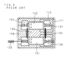
- FIG. 3 shows a sectional view of one of the actuators.
- Reference numerals 101 and 102 denote cylindrical permanent magnets.
- a magnetic material referred to as a pole piece 103 is provided between the permanent magnets 101 and 102, thereby forming magnetic fluxes 110 as shown in FIG. 3.
- the permanent magnets 101 and 102 and the pole piece 103 are surrounded with a hollow cylindrical bobbin 104, which is wound with a coil 105.
- the cylindrical bobbin 104 is fixed inside of a yoke 108 having a lower flat spring 106 and an upper flat spring 107 therebetween.
- a magnetic head 109 is provided at one end of the lower flat spring 106.
- a current is allowed to flow through the coil 105 in the counterclockwise direction seen from the above of the drawing, a force to push down the bobbin 104 is generated owing to the interaction with the magnetic fluxes 110, resulting in lowering the magnetic head 109.
- the magnetic head 109 is raised.
- the conventional rotary drum generally has another magnetic head disposed so as to oppose the above-mentioned magnetic head.
- the rotary drum has another actuator similar to that shown in FIG. 3.
- the first and the second actuators are controlled by first and second control signals, respectively.
- the control process of the second actuator 21B is identical to that of the first actuator 21A except that the phase of the second control voltage to be inputted through the second input terminal 11B is shifted at an angle of 180 degrees from that of the first control voltage.
- the shift between the first control voltage and the second control voltage is caused by the positional difference of the two magnetic heads.
- control signals are supplied to the actuators 21A and 21B, thereby changing the positions of the magnetic heads (shown with the reference numeral 6 in FIG. 1) provided on the actuators 21A and 21B.
- a control signal for driving the actuator is sent to the upper drum by using the brush and the slip-ring as described above.
- a fretting noise as well as an electrical noise caused by temporary noncontact between the brush and the slip-ring are generated.
- such a noise jumps into reproduced signals to cause a white dot noise to appear on a monitoring display.
- the quality of the reproduced image is degraded.
- the contact pressure between the brush and the slip-ring can be raised so as to reduce the number of noises on the display.
- This makes the brush worn rapidly, resulting in shortening the useful life of the brush.
- This method is therefore useful when the brush and the slip-ring can be regularly checked or exchanged, but is nearly impossible to adopt for home appliances which are difficult to be regularly checked. Therefore, it has been desired to develop an inexpensive magnetic head unit of a driving signal transmission system with a high reliability that can be also used for home appliances.
- Document EP-A-0 595 633 discloses a magnetic recording/reproducing apparatus with a circuit means for transferring an audio frequency band FM signal and a control signal for controlling a recording amplifier or a reproducing amplifier through a rotary transformer channel by superposing the control signal with the audio frequency band FM signal.
- Document DE-A-3 722 927 discloses a magnetic head unit with an electromechanical transducer element for moving the magnetic head in the direction crossing the track on a magnetic tape.
- the present invention was attained to solve the above-mentioned problems.
- the objective thereof is providing a signal transmission system for a movable magnetic head unit with a high reliability in which a control signal for the positional change of a magnetic head is steadily and stably transmitted without causing an electrical noise due to a mechanical contact; and providing a movable magnetic head unit in which a magnetic head is set at a predetermined position by electrically compensating the mechanical deviation of the magnetic head caused in the process of mounting the magnetic head on an electromechanical transducing element.
- a rotary magnetic head is mounted on an electromechanical transducing element such as an electromagnetically driven type actuator.
- a control signal for moving the magnetic head in the direction vertical to the track of a magnetic tape is frequency modulated by frequency modulation means, and then, the modulated control signal is supplied to frequency demodulation means via wireless transmission means, which include such as a rotary transformer and optical signal transmission means.
- control signal is transmitted by wireless, by the rotary transformer or through optical transmission in this manner, extremely fewer electrical noises are caused as compared in a conventional contact transmission system using a brush, a slip-ring and the like. Further, there is no need to consider the abrasion of such an element. Therefore, a desired transmission can be steadily and stably conducted.
- a frequency modulated control signal is demodulated at the same carrier frequency as used in the frequency modulation means. Therefore, a crosstalk caused between the control signal and speech and image signals is prevented by transmitting a DC component of the control signal and setting the frequency band of the modulated signal in a desired band.
- the current value of the frequency modulated control signal inputted to the rotary transformer is adjusted based on the level of the recorded or reproduced signal.
- the frequency modulated signal is modulated to have a band which is lower than the luminance carrier frequency band of an image signal, higher than a audio signal carrier frequency band and does not overlap a higher frequency part of the speech carrier frequency band.
- the frequency modulated control signal can be in a band lower than the carrier frequency band of a lowpass band-pass converted color signal.
- the movable magnetic head unit of this invention has a rotary transformer in the transmission means, the rotary transformer has a plurality of coils wound concentrically thereon, and the frequency modulated control signal is applied to the outermost coil among them. In addition, one or both of the coils adjacent to the coil for the frequency modulated control signal are terminated.
- the movable magnetic head unit of this invention has level detection means, which detects the level of a frequency modulated control signal having been transmitted by the rotary transformer and outputs a control signal for setting the magnetic head at a predetermined position to the electromechanical transducing element when the detected level is lower than a desired level.
- the level detection means has a hysteresis against the detection level.
- the control signal when the control signal is lower than a desired level, a mechanical deviation of the rotary magnetic head caused in the mounting process can be electrically compensated so as to place the magnetic head at the predetermined position.
- a larger tolerance can be attained in the accuracy in the components and assembling of the electromechanical transducing element, and the resultant electromechanical transducing element can be used also for home appliances.
- the electromechanical transducing element is prevented from becoming uncontrollable and being damaged due to a sharp level change of a control signal.
- the movable magnetic head unit of this invention has plural electromechanical transducing elements, signal mixing means for mixing frequency modulated control signals having been modulated in the frequency modulation means to be supplied to the transmission means, and signal separation means for separating the frequency modulated control signals from the mixed signal.
- the plural electromechanical transducing elements are controlled by one transmission means.
- a control signal for the positional change of the rotary magnetic head is a digital control signal.
- the parallel control digital signal is converted into a serial control signal, the converted control signal is transmitted via wireless transmission means such as optical signal transmission means to be supplied to digital - analog conversion means.
- the transmission means of the movable magnetic head unit of this invention has digital modulation means for modulating the converted serial control signal, optical signal emitting means for converting the digital modulated control signal into an optical control signal to be outputted, optical signal receiving means for receiving the optical control signal and converting it into a digital control signal, and digital demodulation means for demodulating the converted digital modulated control signal to be supplied to the digital - analog conversion means.
- the movable magnetic head unit of this invention has level detection means for detecting the level of a serial signal transmitted by the optical signal transmission means and outputting a control signal with a desired voltage to the electromechanical transducing element when the detected level is lower than a desired level.
- the level detection means further makes serial - parallel signal conversion means or digital - analog conversion means output a control signal with a desired voltage.
- the level detection means has a hysteresis against the detection level.
- the optical signal receiving means is provided on a rotation axis including the rotation center of the rotary magnetic head.
- the movable magnetic head unit of this invention has plural electromechanical transducing elements, signal mixing means for mixing converted serial control signals to be supplied to the respective electromechanical transducing elements and sending the mixed control signal to the transmission means, and signal separation means for separating the serial control signals from the mixed serial control signal.
- the mixed serial control signals have, in each unit word, an ID code indicating the correspondence to one of the respective electromechanical transducing elements.
- FIG. 1 is a partial cutaway vertical sectional view of a rotary drum used in a conventional transmission system.
- FIG. 2 is a block diagram showing the conventional transmission system.
- FIG. 3 is a sectional view of a conventional actuator.
- FIG. 4 is a block diagram showing part of a magnetic recording/reproducing device according to the present invention.
- FIG. 5 is a partial cutaway vertical sectional view of a rotary drum according to the present invention.
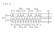
- FIG. 6 shows the arrangement of grooves in a rotary transformer according to the present invention.
- FIG. 7 shows the frequency bands of signals to be transmitted in the rotary transformer.
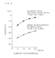
- FIG. 8 shows the recording current - crosstalk characteristics.
- FIG. 9 is a partial cutaway vertical sectional view of another rotary drum according to the present invention.
- FIG. 10 is a block diagram of part of a magnetic recording/reproducing device of Example 2.
- FIG. 11 is a block diagram of part of a magnetic recording/reproducing device of Example 3.
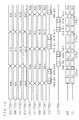
- FIG. 12 shows the timing of the serial signal transmission of Example 3.
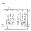
- FIG. 13 is a block diagram showing wireless transmission means of Example 3.
- FIG. 4 is a block diagram showing part of a magnetic recording/reproducing device according to this invention
- FIG. 5 is a partial cutaway vertical sectional view of a rotary drum used in the magnetic recording/reproducing device of FIG. 4.
- an electromagnetically driven type actuator i.e., an electromechanical transducing element; hereinafter referred to as the "actuator”
- 21A is fixed to an upper drum 5 with a screw 9 so as to be rotatable around a rotation axis 3.
- the rotation axis 3 is supported by bearings 4 fixed to a lower drum 2.
- a magnetic tape 1, that is, a magnetic recording medium, is obliquely slided along a tape guide (not shown) on the outer surfaces of the upper drum 5 and the lower drum 2.
- a rotary magnetic head 6 for recording and reproducing an image signal is adhered to the top of a movable plate disposed on the actuator 21A.
- the magnetic head 6 can be moved in the direction along the rotation axis 3 by applying a control signal to the actuator 21A as described in detail below.
- the rotary drum has another similar actuator 21B on the other side of the rotation axis 3 so as to oppose the actuator 21A.
- the control of the actuators 21A and 21B will be described referring to FIG. 4.
- first and second control voltage input terminals 11A and 11B are respectively provided with regard to the first and the second actuators 21A and 21B.
- a first control voltage inputted through the first control voltage input terminal 11A is inputted to a first FM modulator 12A.
- a first carrier frequency f 1 (MHz) is FM modulated to have a desired band by using the first control voltage.
- a second control voltage inputted through the second control voltage input terminal 11B is inputted to a second FM modulator 12B.
- a second carrier frequency f 2 (MHz) is FM modulated to have a desired band by using the second control voltage.
- First and second FM modulated signals respectively outputted from the first and the second FM modulators 12A and 12B are inputted to signal mixing means 13, in which respective FM modulated signals are mixed to be outputted.
- the FM modulated signal outputted from the signal mixing means 13 is inputted to a gain control amplifier 14, thereby supplying a desired current to a supplying coil in a rotary transformer 40.
- a gain control signal is inputted to the gain control amplifier 14 through a gain control input terminal 22, thereby adjusting the value of a current to be outputted to the rotary transformer 40 in accordance with the operation mode of the magnetic head 6.
- a coil for transmitting a control signal for the actuator and coils for image and audio signals are concentrically wound in the rotary transformer 40. Therefore, the control signal for the actuator can give a crosstalk to the coils for image and audio signals or receive a crosstalk from the other coils described below depending upon the operation mode of the magnetic head 6. For example, in the recording mode, since a large current for recording flows through the coils for image and audio signals, the coil for a control signal for the actuator tends to receive a crosstalk due to the large current. In such a case, the current value of the control signal for the actuator is raised, thereby avoiding the crosstalk.
- a control signal for the actuator indicates an FM modulated signal to be supplied from the gain control amplifier 14 to the supplying coil in the rotary transformer 40.
- the rotary transformer 40 is constituted of an upper transformer 34 and a lower transformer 33.
- the upper transformer 34 is fixed to the upper drum 5 so as to be rotatable around the rotation axis 3.
- On a surface of the upper transformer 34 opposing the lower transformer 33 a plurality of grooves are formed concentrically with the rotation axis 3, and a coil is provided in each of these grooves.
- the lower transformer 33 is fixed to the lower drum 2.
- FIG. 6 is a vertical sectional view of the rotary transformer 40.
- a groove 61a for the coil for transmitting a control signal for the actuator is formed in the outermost portion.
- grooves are also formed so as to face the above-mentioned grooves. As shown in FIG. 6, the grooves shown with the same reference numeral followed by a or b make one pair.
- a groove 58a formed between the grooves 57a and 59a and a groove 58b facing the groove 58a are used for coils for transmitting signals for erasing recorded signals on the magnetic tape.
- Grooves 53, 56 and 60 formed on the lower transformer 33 are designated as short rings, each of which contains a coil whose ends are connected to each other. Such a short ring works for reducing the number of crosstalks between the adjacent coils as described below.
- the FM modulated signal supplied to the rotary transformer 40 is transmitted to a receiving coil in the rotary transformer 40, and is inputted to a preamplifier 16 to be amplified as shown in FIG. 4.
- the output signal from the preamplifier 16 is inputted to first and second band-pass filters 17A and 17B.
- a first FM modulated signal with a band including the first carrier frequency f 1 (MHz) at the center is extracted in the first band-pass filter 17A
- a second FM modulated signal with a band including the second carrier frequency f 2 (MHz) at the center is extracted in the second band-pass filter 17B.
- the extracted first FM modulated signal is inputted to a first FM demodulator 18A, in which the first FM modulated signal is demodulated into a first control signal substantially identical to the original first control signal.
- the extracted second FM modulated signal is inputted to a second FM demodulator 18B, in which the second FM modulated signal is demodulated into a second control signal substantially identical to the original second control signal.
- the first and the second FM modulated signals are also inputted to input signal level detection means 23.
- a first control signal inputted from the input terminal 11A with a predetermined voltage value of, for example, 2.5 V is modulated to have a predetermined carrier frequency f 1 of, for example, 2.4 MHz, and the carrier signal of 2.4 MHz is demodulated into the control signal of 2.5 V in the demodulation process.
- a second control signal with a predetermined voltage value of, for example, 2.5 V is modulated to have a predetermined carrier frequency f 2 of, for example, 2.8 MHz, and the carrier signal of 2.8 MHz is demodulated into the control signal of 2.5 V.
- the demodulated signals from the first and the second FM demodulator 18A and 18B are respectively inputted to first and second amplifiers 27A and 27B each having a voltage shifting function, and then to the first and the second actuators 21A and 21B.
- the input signal level detection means 23 detects the signal transmission in accordance with the output level of the signals inputted from the first and the second band-pass filters 17A and 17B. As a result of the detection, the input signal level detection means 23 outputs signals to first and second power amplifiers 28A and 28B. For example, when one or both of the first and the second FM modulated signals have a low level, or when a supply voltage is applied, the input signal level detection means 23 outputs signals to the first and the second power amplifiers 28A and 28B. This output of the signals allows the first and the second power amplifiers 28A and 28B to supply a predetermined control voltage to the first and the second actuators 21A and 21B, thereby setting the initial position of the magnetic head at a predetermined position.
- the initial position of the magnetic head with regard to the rotation axis depends upon the assembling accuracy of the actuator itself. It is practically impossible to construct the actuator at an accuracy of several microns so as to place the magnetic head at a predetermined position with regard to the rotation axis. As a result, the initial position of the magnetic head assembled in the rotary drum is deviated from the predetermined position. The initial positional deviation of the magnetic head is therefore electrically compensated by applying a control voltage with a predetermined value to the actuator.
- the actuators 21A and 21B work as a resonator having the magnetic heads, and have a mechanical resonance point indicated as a resonance frequency f 0 . If an output signal is intermittently generated from the input signal level detection means 23 when the position of the magnetic head is largely deviated, the actuators 21A and 21B resonate at the resonance frequency f 0 . As a result, the actuators 21A and 21B not only become uncontrollable but also can be damaged. In order to avoid this, the input signal level detection means 23 is allowed to have a hysteresis against the detection level, thereby preventing the intermittent generation of the output voltage.
- a portion surrounded with a broken line in FIG. 4 indicates a circuit block to be provided on the upper drum 5.
- first and second control signals for controlling the positional change of the respective magnetic heads are respectively inputted through the first and the second input terminals 11A and 11B to be FM modulated.
- a luminance signal component i.e., a Y signal
- a color signal component i.e., a C signal
- a carrier signal is FM modulated by the Y signal and the C signal is converted into a low frequency signal.
- a carrier signal different from that used in the FM modulation by the Y signal is FM modulated in each channel.
- FIG. 7 is a graph showing the relationship between the frequency of each signal applied to the magnetic head and the signal level.
- Y 1 indicates the band of the carrier of the FM modulated signal, i.e., the luminance signal frequency band.
- Y 1 On the lower frequency side of the luminance signal frequency band Y 1 is a lower side frequency band Y 2 .
- Y 2 On the still lower frequency side of the lower side frequency band Y 2 is a band S of an FM modulated audio signal. A plurality of speech carriers are present in the band S.
- On the still lower frequency side of the band S is a band C of a low-pass band-pass color signal.
- the first and the second carrier frequencies of the first and the second control signals are lower than the luminance signal frequency band Y 1 and higher than the audio signal band S. Further, the first and the second carrier frequencies are set so as not to overlap the higher frequency part in the audio signal carrier frequency.
- the first and the second FM modulated signals that have been FM modulated in the above-mentioned manner are mixed to synthesize a control signal, which is transmitted by wireless from the lower transformer 33 of the rotary transformer 40 to the upper transformer 34. Since the FM modulated signal has the above described modulation band, the FM modulated signals transmitted in the rotary transformer tends not to give or receive a crosstalk to or from audio signals.
- FIG. 8 shows the data on the crosstalk characteristics.
- a crosstalk given from the coil for a audio signal to the adjacent coil for a control signal is shown with ⁇
- a crosstalk given from the coil for a audio signal to the coil for a control signal when a short ring is disposed therebetween is shown with ⁇ .
- the transmission frequency of the audio signal is 1.3 MHz.
- the presence of the short ring can reduce the number of crosstalks by more than 20 dB.
- a coil for a control signal When a coil for a control signal is wound in the outermost groove of the rotary transformer 40 as in this example, one short ring is required in the inner portion.
- the position of the groove for a control signal is not limited to this and can be between the grooves for an image signal or a audio signal. In the latter case, short rings are required to be formed so as to sandwich a groove for a control signal. Since the coupling coefficient of the rotary transformer becomes higher toward the rotation center thereof, it is generally preferred that a groove for an image signal is formed in the innermost portion and followed by the grooves for a audio signal and a control signal.
- the FM modulated signal having been transmitted by wireless via the rotary transformer 40 is separated, extracted and demodulated through the first and the second band-pass filters 17A and 17B to be supplied to the first and the second actuators 21A and 21B. Since a control signal for the actuator is transmitted through noncontact transmission in this manner, the magnetic head can stably trace the magnetic tape.
- the first and the second carrier frequency bands a frequency band that is lower than the color signal band C of FIG. 7 and is higher than the transmission lower limit frequency of the rotary transformer.
- FIG. 9 is a partial cutaway vertical sectional view of a rotary drum used in a magnetic recording/reproducing device of this example.
- FIG. 10 is a block diagram showing part of the magnetic recording/reproducing device.
- an actuator 21A is fixed to an upper drum 5 with a screw 9 so as to be rotatable around a rotation axis 3.
- a rotary magnetic head 6 for recording and reproducing an image signal is adhered to the top of a movable plate disposed on the actuator 21A.
- a lower transformer 33 is fixed to a lower drum 2, and forms a rotary transformer together with a rotatable upper transformer 34 fixed to the upper drum 5.
- a signal to be recorded on a magnetic tape is transmitted from a coil in the lower transformer 33 to a coil in the upper transformer 34 to be supplied to the magnetic head 6.
- the magnetic head 6 reads a signal from the magnetic tape, and the read signal is transmitted by the reverse route.
- An optical signal receiving element 45 is provided on a shaft including the rotation center of the rotation axis 3.
- An optical signal emitting element 44 disposed on a mounting member 46 is provided obliquely above the optical signal receiving element 45.
- the optical signal receiving element 45 receives an optical signal from the optical signal emitting element 44.
- the optical signal receiving element 45 has a lens with a converging effect at the top, and this lens makes large the tolerance in the mounting position of the optical signal emitting element 44.
- the optical signal sent from the optical signal emitting element 44 is a control signal for the actuator. By supplying the control signal to the actuator 21A, the magnetic head 6 can be moved in the direction along the rotation axis 3.
- a photodiode and a phototransistor are generally used as the optical signal emitting element 44 and the optical signal receiving element 45, respectively.
- the optical signal receiving element 45 and the optical signal emitting element 44 are disposed above the rotation axis 3.
- the positions of these elements are, however, not limited to the above, and can be below the rotation axis 3 as occasion demands. When these elements are below the rotation axis 3, they can be advantageously shaded from an interference light.
- the rotary drum has another similar actuator 21B on the other side of the rotation axis 3 so as to oppose the actuator 21A.
- These two actuators are controlled as follows:
- reference numerals 11A and 11B denote first and second control voltage input terminals, through which control signals for the actuators are inputted.
- a first control voltage inputted through the first control voltage input terminal 11A is inputted to a first FM modulator 12A.
- a first carrier frequency f 1 (MHz) is FM modulated to have a predetermined band by using the first control voltage.
- a second control voltage inputted through the second control voltage input terminal 11B is inputted to a second FM modulator 12B.
- a second carrier frequency f 2 (MHz) is FM modulated to have a predetermined band by using the second control voltage.
- First and second FM modulated signals outputted from the first and the second FM modulators 12A and 12B are inputted to signal mixing means 13, in which the respective modulated signals are mixed to be outputted.
- the frequency modulated signal outputted from the signal mixing means 13 is inputted to optical signal emission means 42 including the optical signal emitting element 44.
- the optical signal emission means 42 emits an optical spectrum having an intensity in accordance with the level of the inputted frequency modulated signal.
- the optical spectrum is received by optical signal receiving means 43 including the optical signal receiving element 45 to be converted into an FM modulated signal substantially identical to the original FM modulated signal.
- the optical signal emission means 42 and the optical signal receiving means 43 form optical signal transmission means 41.
- the FM modulated signal outputted from the optical signal receiving means 43 is inputted to first and second band-pass filters 17A and 17B, where first and second FM modulated signals are extracted. These extracted FM modulated signals are supplied to the first and the second actuators 21A and 21B as the first and the second control signals in the same manner as in Example 1 shown in FIG. 4.
- the same reference numerals as in FIG. 4 are used to refer to the same elements, and the description thereof is omitted.
- a control signal for controlling the positional change of each magnetic head is transmitted by wireless by the optical signal transmission means 41 to be supplied to each of the actuators 21A and 21B.
- the magnetic head can stably trace the magnetic tape.
- both modulation and demodulation are conducted by using a control signal having a predetermined voltage value and a predetermined FM modulation frequency corresponding to the voltage value, as in Example 1.
- the DC component of the control signal can be transmitted even through the modulation/demodulation process.
- the level of the transmitted FM modulated signal is detected by input signal level detection means 23.
- a desired voltage is supplied to a power amplifier.
- the initial position of the magnetic head can be thus compensated.
- optical signal transmission means 41 can be easily fabricated by using the similar technique to that used in such equipment.
- FIG. 11 is a block diagram showing part of a magnetic recording/reproducing device of this example.
- Control signal generation means 71 generates a control signal corresponding to a control voltage to be applied to each of actuators 21A and 21B.
- a first control signal is a parallel signal comprising plural bits represented by 72A through 72H and a second control signal is a parallel signal comprising plural bits represented by 73A through 73H.
- Such a parallel signal i.e., a control signal is inputted to first and second parallel/serial signal conversion means (hereinafter referred to as the "P/S signal conversion means") 74A and 74B from the control signal generation means 71.
- P/S signal conversion means first and second parallel/serial signal conversion means
- the first P/S signal conversion means 74A converts the first control signal into a serial signal 75A strung one bit by one bit of the parallel signal.
- the second P/S signal conversion means 74B converts one bit string of the second control signal into a serial signal 75B.
- FIG. 12 shows the transmission timing of the control signals and of those converted as described below.
- AA, BB, CC and DD indicate four bits of a parallel signal constituting a first control signal.
- Bits 72A, 72B, 72G and 72H are herein exemplified.
- Such a first control signal is P/S converted as one unit word by the first P/S signal conversion means 74A.
- a P/S converted serial signal 75A denoted by II in FIG. 12 is inputted to wireless transmission means 76.
- EE, FF, GG and HH indicate four bits of a parallel signal constituting a second control signal.
- Bits 73A, 73B, 73G and 73H are herein exemplified.
- Such a second control signal is P/S converted as one unit word by the second P/S signal conversion means 74B.
- a P/S converted serial signal 75B denoted by JJ in FIG. 12 is also inputted to the wireless transmission means 76.
- FIG. 13 is a block diagram showing the structure of the wireless transmission means 76.
- the serial signals 75A and 75B respectively outputted from the first and the second P/S signal conversion means 74A and 74B are inputted to digital modulation means 85 in the wireless transmission means 76.
- the digital modulation means 85 includes signal mixing means 87, and performs digital modulation such as pulse position modulation by mixing the inputted serial signals 75A and 75B.
- a digital modulated serial signal KK having been modulated in the digital modulation means 85 by mixing the signals II and JJ shown in FIG. 12 is inputted to optical signal emission means 42. Then, an ID word is added to each unit word of the digital modulated serial signal KK as is shown as a digital modulated serial signal LL in FIG. 12.
- the optical signal emission means 42 transmits by wireless the digital modulated serial signal LL by using an optical signal as a carrier. In this manner, the data carried by the first control signal and that carried by the second control signal are alternately transmitted through one transmission route.
- the contents of the ID word added to the digital modulated serial signal LL are used as additional information for control or for a synchronizing treatment of the serial signal transmission.
- the ID word can be added to either end of each unit word. Further, when the ID word is added to a portion regarding either the first control signal or the second control signal alone, the same effect can be attained.
- optical signal receiving means 43 The optical signal having been transmitted by wireless is received by optical signal receiving means 43.
- the optical signal receiving means 43 has a signal detection element above the rotation axis as that shown in FIG. 9.
- the optical signal having been received by the optical signal receiving means 43 is inputted to digital demodulation means 86.
- the digital demodulation means 86 includes signal separation means 88, and demodulates and separates the optical signal into serial signals 77A and 77B.
- serial signals 77A and 77B are inputted to first and second serial/parallel signal conversion means (hereinafter referred to as the "S/P signal conversion means") 78A and 78B as shown in FIG. 11. Therefore, the signals 75A and 75B are substantially identical to the signals 77A and 77B, respectively.
- the first S/P signal conversion means 78A converts the inputted serial signal 77A into a parallel signal comprising plural bits represented by 79A through 79H, and outputs the parallel signal to first digital/analog conversion means (hereinafter referred to as the "D/A conversion means") 81A.
- the second S/P signal conversion means 78B converts the inputted serial signal 77B into a parallel signal comprising plural bits represented by 80A through 80H, and outputs the parallel signal to second A/D conversion means 81B.
- the serial signals 77A and 77B outputted from the wireless transmission means 76 are also inputted to input signal level detection means 82.
- the input signal level detection means 82 When one or both of these serial signals have a low level or when a supply voltage is applied, the input signal level detection means 82 generates an output signal. Owing to this output signal, a control voltage to be supplied to the first and the second actuators 21A and 21B is adjusted to have a predetermined value.
- the output from the input signal level detection means 82 is inputted to the first and the second S/P conversion means 78A and 78B as shown with a solid line with an arrow in FIG. 11.
- the first and the second S/P conversion means 78A and 78B output predetermined digital values to the first and the second D/A conversion means 81A and 81B.
- the output from the input signal level detection means 82 is inputted to the first and the second D/A conversion means 81A and 81B as shown with a dashed line with an arrow in FIG. 11.
- the first and the second D/A conversion means 81A and 81B output predetermined analog voltage values to first and second amplifiers 27A and 27B.
- the output from the input signal level detection means 82 is inputted to the first and the second amplifiers 27A and 27B or to first and second power amplifiers 28A and 28B as shown with a broken line with an arrow in FIG. 11.
- the first and the second amplifiers 27A and 27B or the first and the second power amplifiers 28A and 28B supply predetermined control voltages to the first and the second actuators 21A and 21B.
- a control voltage to be supplied to the actuators can be set at a predetermined value, resulting in compensating the initial position of the magnetic head as described in Example 1.
- the input signal level detection means 82 it is also useful to allow the input signal level detection means 82 to have a hysteresis against the detection level in order to avoid the damage of the actuators due to the mechanical resonance.
- a digital signal for controlling the positional change of the magnetic head is converted into a serial signal, pulse position modulated, and transmitted by wireless.
- the transmitted signal is demodulated, converted into a parallel signal, and converted into an analog signal to be supplied to the actuator. Since a control signal is transmitted through noncontact transmission in this manner, the magnetic head can stably trance the magnetic tape. Further, since the DC component to be transmitted is included in the digital value, less electrical adjustment such as adjustment of a carrier frequency is required in this example than in the aforementioned examples in which transmission is performed by using an FM modulated signal. As a result, the system provided by this example is stable also in point of transmission time.
- a magnetic recording/reproducing device is exemplified as a magnetic head unit.
- the present invention is not limited to this, and can be adopted in any magnetic recording device or magnetic reproducing device having a movable magnetic head.
- the invention can also be used in a DAT (digital audio tape recorder) having a movable magnetic head for recording/reproducing a audio signal.
- the present invention can effectively attain a stably operable and highly reliable system for a magnetic recording/reproducing device using a driving element such as an electromagnetically driven type actuator for the positional change of the magnetic head because a control signal to be supplied to the driving element is transmitted through noncontact transmission. Moreover, since it is possible to electrically compensate the initial position of the magnetic head that is generally deviated depending upon accuracy in the components and assembling of the electromagnetically driven type actuator, inexpensive components can be used to fabricate the actuator. Therefore, the present invention provides a system also useful for home appliances.
Landscapes
- Adjustment Of The Magnetic Head Position Track Following On Tapes (AREA)
- Recording Or Reproducing By Magnetic Means (AREA)
Claims (23)
- Unité formant tête magnétique mobile, comprenant : une tête magnétique rotative (6) pour suivre une piste d'une bande magnétique (1) ;caractérisée en ce queun moyen (12A, 12B) de modulation de fréquence pour moduler en fréquence un signal de commande pour changer la position de ladite tête magnétique afin de générer un signal de commande modulé en fréquence ;un moyen (18A, 18B) de démodulation de fréquence pour démoduler un signal de commande modulé en fréquence ayant été modulé par ledit moyen (12A, 12B) de modulation de fréquence pour générer un signal de commande démodulé en fréquence ;un moyen (40) de transmission pour transmettre le signal modulé en fréquence en provenance dudit moyen (12A, 12B) de modulation de fréquence audit moyen (18A, 18B) de démodulation de fréquence ; etun élément (21A) de transduction électromécanique pour déplacer ladite tête magnétique rotative (6) dans la direction croisant la piste de ladite bande magnétique (1), ledit élément (21A) de transduction électromécanique portant ladite tête magnétique rotative (6),le signal de commande démodulé en fréquence est appliqué audit élément (21A) de transduction électromécanique pour commander ledit élément (21A) de transduction électromécanique, etledit moyen (40) de transmission comporte un transformateur rotatif (33, 34) comportant une pluralité de bobinages concentriques (51 - 61) enroulés sur celui-ci, un bobinage situé le plus à l'extérieur (61) de la pluralité de bobinages concentriques transmettant le signal de commande modulé en fréquence.
- Unité formant tête magnétique mobile selon la revendication 1, caractérisée en ce que ledit moyen (18A, 18B) de démodulation de fréquence démodule le signal de commande modulé en fréquence à la même fréquence porteuse que celle utilisée dans ledit moyen (12A, 12B) de modulation de fréquence.
- Unité formant tête magnétique mobile selon la revendication 1 ou 2, caractérisée par un moyen (23) de réglage pour régler une valeur en cours du signal de commande modulé en fréquence sur la base du niveau d'un signal destiné à être enregistré sur et/ou reproduit à partir de ladite bande magnétique (1),
dans laquelle ledit transformateur rotatif (33, 34) comporte des bobinages pour transmettre le signal à enregistrer sur et/ou reproduit à partir de ladite bande magnétique (1). - Unité formant tête magnétique mobile selon l'une des revendications 1 à 3, caractérisée en ce que le signal de commande modulé en fréquence a une bande qui est inférieure à une bande de fréquence porteuse de signal de luminance d'un signal d'image et supérieure à une bande de fréquence porteuse de signal audio et qui ne recouvre pas une partie de fréquence supérieure de la bande de fréquence porteuse de signal audio.
- Unité formant tête magnétique mobile selon l'une des revendications 1 à 3, caractérisée en ce que le signal modulé en fréquence a une bande inférieure à une bande de fréquence porteuse de signal couleur converti passe-bas passe-bande.
- Unité formant tête magnétique mobile selon l'une des revendications 1 à 5, dans laquelle au moins l'un (60) des bobinages adjacents au bobinage (61) pour transmettre le signal de commande modulé en fréquence, est terminé.
- Unité formant tête magnétique mobile selon l'une des revendications 1 à 6, comprenant en outre :
un moyen (23) de détection de niveau pour détecter le niveau du signal de commande modulé en fréquence ayant été transmis par ledit transformateur rotatif (40) et pour délivrer le signal de commande pour changer la position de ladite tête magnétique (6) pour une position prédéterminée pour ledit élément (21A) de transduction électromécanique, lorsque le niveau détecté est inférieur à un niveau souhaité. - Unité formant tête magnétique mobile selon la revendication 7, dans laquelle ledit moyen (23) de détection de niveau a une caractéristique d'hystérésis fonction d'un niveau de détection.
- Unité formant tête magnétique mobile selon la revendication 1, caractérisée en ce que chacun de ladite tête magnétique rotative (6), dudit élément (21A) de transduction électromécanique, dudit moyen (12A, 12B) de modulation de fréquence, et dudit moyen (18A, 18B) de démodulation de fréquence est en nombre pluriel ; et
ledit moyen (12A, 12B) de modulation de fréquence module en fréquence des signaux de commande destinés à être appliqués respectivement auxdits éléments de transduction électromécanique, les signaux de commande étant modulés en utilisant des signaux de porteuse ayant respectivement différentes fréquences,
en ce que sont utilisésun moyen (13) de mélange de signaux pour mélanger les signaux de commande modulés en fréquence ayant été modulés par ledit moyen de modulation de fréquence pour générer un signal mélangé ; etun moyen (17A, 17B) de séparation de signaux pour séparer le signal mélangé, mélangé par ledit moyen de mélange, en une pluralité de signaux de commande modulés en fréquence, le signal mélangé étant transmis audit moyen de séparation de signaux par ledit transformateur rotatif. - Unité formant tête magnétique mobile, comprenant : une tête magnétique rotative (6) pour suivre une piste d'une bande magnétique (1) ;caractérisée en ce que ledit moyen (18A, 18B) de démodulation de fréquence démodule le signal de commande modulé en fréquence à la même fréquence porteuse que celle utilisée dans ledit moyen (12A, 12B) de modulation de fréquence, etun moyen (12A, 12B) de modulation de fréquence pour moduler en fréquence un signal de commande pour changer la position de ladite tête magnétique afin de générer un signal de commande modulé en fréquence ;un moyen (18A, 18B) de démodulation de fréquence pour démoduler un signal de commande modulé en fréquence ayant été modulé par ledit moyen (12A, 12B) de modulation de fréquence pour générer un signal de commande démodulé en fréquence ;un moyen (41) de transmission pour transmettre le signal de commande modulé en fréquence en provenance dudit moyen (12A, 12B) de modulation de fréquence audit moyen (18A, 18B) de démodulation de fréquence ; etun élément (21A) de transduction électromécanique pour déplacer ladite tête magnétique rotative (6) dans la direction croisant la piste de ladite bande magnétique (1), ledit élément (21A) de transduction électromécanique portant ladite tête magnétique rotative (6), le signal de commande démodulé en fréquence étant appliqué audit élément (21A) de transduction électromécanique pour commander ledit élément (21A) de transduction électromécanique,
ledit moyen (41) de transmission comporte un moyen (42) d'émission de signal optique pour convertir le signal de commande modulé en fréquence en un signal optique destiné à être émis, et un moyen (43) de réception de signal optique pour recevoir le signal optique destiné à être converti en un signal de commande modulé en fréquence. - Unité formant tête magnétique mobile selon la revendication 10, comprenant en outre :
un moyen (23) de détection de niveau pour détecter un niveau du signal modulé en fréquence ayant été reçu par ledit moyen (43) de réception de signal optique et appliquer le signal de commande pour changer la position de ladite tête magnétique (6) pour une position prédéterminée pour ledit élément (21A) de transduction électromécanique, lorsque le niveau détecté est inférieur à un niveau souhaité. - Unité formant tête magnétique mobile selon la revendication 11, dans laquelle ledit moyen (23) de détection de niveau a une caractéristique d'hystérésis fonction d'un niveau de détection.
- Unité formant tête magnétique mobile selon la revendication 10, caractérisée par une pluralité de têtes magnétiques rotatives (6) ;une pluralité d'éléments (21A, 21B) de transduction électromécanique portant chacun l'une desdites têtes magnétiques rotatives (6) ;une pluralité de moyens (12A, 12B) de modulation de fréquence pour moduler en fréquence des signaux de commande étant modulés en utilisant des signaux de porteuse ayant respectivement différentes fréquences pour générer une pluralité de signaux de commande modulés en fréquence ;un moyen (13) de mélange de signaux pour mélanger les signaux modulés en fréquence ayant été modulés par ledit moyen (12A, 12B) de modulation de fréquence afin de générer un signal mélangé ;un moyen (17A, 17B) de séparation de signaux pour séparer le signal mélangé, mélangé par ledit moyen (13) de mélange, en une pluralité de signaux de commande modulés en fréquence ; etune pluralité de moyens (18A, 18B) de démodulation de fréquence pour démoduler les signaux de commande modulés en fréquence.
- Unité formant tête magnétique mobile selon la revendication 10 ou 13, dans laquelle ledit moyen (43) de réception de signal optique est disposé sur un axe de rotation (3) incluant le centre de rotation de ladite tête magnétique rotative (6).
- Unité formant tête magnétique mobile comprenant :caractérisée parune tête magnétique rotative (6) pour suivre une piste d'une bande magnétique (1) ;un élément (21A, 21B) de transduction électromécanique pour déplacer ladite tête magnétique rotative (6) dans la direction croisant la piste de ladite bande magnétique (1), ledit élément (21A, 21B) de transduction électromécanique portant ladite tête magnétique rotative (6) ;un moyen (71) de génération de signal de commande pour générer un signal de commande pour changer la position de ladite tête magnétique (6) sous la forme d'un signal numérique parallèle ;un moyen (74A, 74B) de conversion de signal parallèle-série pour convertir le signal de commande numérique parallèle en un signal de commande série ; etun moyen (78A, 78B) de conversion de signal série-parallèle pour convertir le signal de commande série, ayant été converti par ledit moyen (74A, 74B) de conversion de signal parallèle-série, en un deuxième signal de commande parallèle,un moyen (76) de transmission pour transmettre par une transmission sans fil le signal de commande série en provenance dudit moyen (74A, 74B) de conversion de signal parallèle-série, audit moyen (78A, 78B) de conversion de signal série-parallèle, etun moyen (81A, 81B) de conversion numérique-analogique pour convertir le deuxième signal de commande parallèle, ayant été converti par ledit moyen (78A, 78B) de conversion de signal série-parallèle, en un signal analogique destiné à être appliqué audit élément (21A, 21B) de transduction électromécanique pour commander ledit élément (21A , 21B) de transduction électromécanique.
- Unité formant tête magnétique mobile selon la revendication 15, dans laquelle ledit moyen (76) de transmission comporte :un moyen (85) de modulation numérique pour moduler numériquement le signal série délivré par ledit moyen (74A, 74B) de conversion de signal parallèle-série, afin de générer un signal de commande modulé numérique ;un moyen (42) d'émission de signal optique pour convertir le signal de commande modulé numérique, ayant été converti par ledit moyen (85) de modulation numérique, en un signal de commande optique destiné à être émis. ;un moyen (43) de réception de signal de commande optique pour recevoir le signal de commande optique et le convertir en un signal de commande modulé numérique ; etun moyen (86) de démodulation numérique pour démoduler le signal de commande modulé numérique délivré par ledit moyen (43) de réception de signal optique pour être appliqué audit moyen (81A, 81B) de conversion numérique-analogique.
- Unité formant tête magnétique mobile selon la revendication 16, dans laquelle ledit moyen (43) de réception de signal de commande optique est disposé sur un axe de rotation (3) incluant le centre de rotation de ladite tête magnétique rotative (6).
- Unité formant tête magnétique mobile selon la revendication 15, comprenant en outre un moyen (82) de détection de niveau pour détecter le niveau du signal de commande série transmis par ledit moyen (76) de transmission et permettant une sortie du signal de commande pour changer la position de ladite tête magnétique (6) pour une position prédéterminée pour ledit élément (21A, 21B) de transduction électromécanique, lorsque le niveau détecté est inférieur à un niveau souhaité.
- Unité formant tête magnétique mobile selon la revendication 18, dans laquelle ledit moyen (82) de détection de niveau a une caractéristique d'hystérésis fonction du niveau de détection.
- Unité formant tête magnétique mobile selon la revendication 15, comprenant en outre un moyen (82) de détection de niveau pour détecter le niveau du signal de commande série transmis par ledit moyen (76) de transmission et faisant en sorte que ledit moyen (78A, 78B) de conversion de signal série-parallèle délivre le signal de commande pour changer la position de ladite tête magnétique (6) pour une position prédéterminée.
- Unité formant tête magnétique mobile selon la revendication 15, comprenant en outre un moyen (82) de détection de niveau pour détecter le niveau du signal de commande série transmis par ledit moyen (76) de transmission et faisant en sorte que ledit moyen (81A, 81B) de conversion numérique-analogique délivre le signal de commande pour changer la position de ladite tête magnétique (6) vers une position prédéterminée.
- Unité formant tête magnétique mobile selon la revendication 16,dans laquelle ledit élément (21A, 21B) de transduction électromécanique est en nombre pluriel,ledit moyen (74A, 74B) de conversion de signal parallèle-série convertit une pluralité de signaux de commande destinés à être appliqués respectivement auxdits éléments (21A, 21B) de transduction électromécanique en signaux de commande série à des instants respectivement différents,ledit moyen (85) de modulation numérique comporte un moyen (87) de mélange pour mélanger les signaux de commande série avant une modulation numérique, etledit moyen (86) de démodulation numérique comporte un moyen (88) de séparation pour séparer les signaux de commande série mélangés destinés à être appliqués audit moyen (81A, 81B) de conversion numérique-analogique après démodulation du signal de commande modulé numérique.
- Unité formant tête magnétique mobile selon la revendication 22, dans laquelle le signal de commande série mélangé comporte, dans chaque mot unitaire, un code ID indiquant une correspondance avec l'un desdits éléments (21A, 21B) de transduction électromécanique.
Applications Claiming Priority (3)
| Application Number | Priority Date | Filing Date | Title |
|---|---|---|---|
| JP16686793A JP3243470B2 (ja) | 1993-07-06 | 1993-07-06 | 磁気記録再生装置 |
| JP16686793 | 1993-07-06 | ||
| JP166867/93 | 1993-07-06 |
Publications (3)
| Publication Number | Publication Date |
|---|---|
| EP0633562A2 EP0633562A2 (fr) | 1995-01-11 |
| EP0633562A3 EP0633562A3 (fr) | 1995-02-22 |
| EP0633562B1 true EP0633562B1 (fr) | 2001-10-17 |
Family
ID=15839111
Family Applications (1)
| Application Number | Title | Priority Date | Filing Date |
|---|---|---|---|
| EP94110488A Expired - Lifetime EP0633562B1 (fr) | 1993-07-06 | 1994-07-06 | Unité de tête magnétique mobile |
Country Status (4)
| Country | Link |
|---|---|
| US (2) | US5675449A (fr) |
| EP (1) | EP0633562B1 (fr) |
| JP (1) | JP3243470B2 (fr) |
| DE (1) | DE69428639T2 (fr) |
Families Citing this family (5)
| Publication number | Priority date | Publication date | Assignee | Title |
|---|---|---|---|---|
| US6243240B1 (en) * | 1996-12-17 | 2001-06-05 | Sony Corporation | Non-contact type transmission device and rotary magnetic head unit having the non-contact type transmission device |
| JP2001006102A (ja) * | 1999-06-16 | 2001-01-12 | Sony Corp | 信号処理装置および方法 |
| US7533403B1 (en) * | 2002-08-23 | 2009-05-12 | Vulcan Ventures, Inc. | Apparatus and method for distributing audio and video content using existing network wiring |
| US6977509B2 (en) * | 2004-03-17 | 2005-12-20 | Clinton Instrument Company | System and method for high voltage testing of twisted insulated conductors |
| US9718193B1 (en) * | 2015-12-09 | 2017-08-01 | X Development Llc | Rotary transformer |
Family Cites Families (15)
| Publication number | Priority date | Publication date | Assignee | Title |
|---|---|---|---|---|
| JPS5436709A (en) * | 1977-08-26 | 1979-03-17 | Sony Corp | Position control circuit for rotary magnetic head |
| JPS5919206A (ja) * | 1982-07-24 | 1984-01-31 | Sony Corp | 磁気記録装置 |
| US4485418A (en) * | 1982-08-12 | 1984-11-27 | Magnetic Peripherals, Inc. | System and method of locating the center of a track on a magnetic storage disk |
| JPH071521B2 (ja) * | 1985-11-11 | 1995-01-11 | キヤノン株式会社 | 記録再生装置 |
| DE3722927A1 (de) * | 1986-07-16 | 1988-01-21 | Mitsubishi Electric Corp | Kopftrommelanordnung |
| US4819096A (en) * | 1986-10-23 | 1989-04-04 | Datatape Incorporated | Rotary head scanner including anamorphic beam-shaping apparatus in an optical signal-transmission channel |
| DE3705928A1 (de) * | 1987-02-25 | 1988-09-08 | Broadcast Television Syst | Megnetbandgeraet mit vorrichtung zur beruehrungslosen uebertragung von signalen zwischen relativ zueinander bewegten bauteilen |
| JPS6423401A (en) * | 1987-07-20 | 1989-01-26 | Victor Company Of Japan | Magnetic recording and reproducing device |
| JPH01303605A (ja) * | 1988-05-31 | 1989-12-07 | Fujitsu General Ltd | 磁気記録および/または再生装置 |
| US4967290A (en) * | 1988-08-26 | 1990-10-30 | Datatape Incorporated | Multiple channel rotary magnetic head scanner having stackable electro-optical signal transmission modules |
| JP2623751B2 (ja) * | 1988-08-30 | 1997-06-25 | ソニー株式会社 | 記録制御信号の伝送方法および記録制御回路 |
| JPH073688B2 (ja) * | 1989-09-11 | 1995-01-18 | 三菱電機株式会社 | 磁気再生装置 |
| JP2595752B2 (ja) * | 1990-03-27 | 1997-04-02 | 三菱電機株式会社 | 磁気記録再生装置 |
| JP2529463B2 (ja) * | 1990-11-21 | 1996-08-28 | 松下電器産業株式会社 | ディジタル信号磁気記録装置 |
| KR940010038A (ko) * | 1992-10-28 | 1994-05-24 | 사또오 후미오 | 자기 기록 재생 장치 |
-
1993
- 1993-07-06 JP JP16686793A patent/JP3243470B2/ja not_active Expired - Fee Related
-
1994
- 1994-07-05 US US08/266,893 patent/US5675449A/en not_active Expired - Fee Related
- 1994-07-06 EP EP94110488A patent/EP0633562B1/fr not_active Expired - Lifetime
- 1994-07-06 DE DE69428639T patent/DE69428639T2/de not_active Expired - Fee Related
-
1997
- 1997-05-09 US US08/852,961 patent/US5933289A/en not_active Expired - Fee Related
Also Published As
| Publication number | Publication date |
|---|---|
| DE69428639D1 (de) | 2001-11-22 |
| US5933289A (en) | 1999-08-03 |
| EP0633562A3 (fr) | 1995-02-22 |
| EP0633562A2 (fr) | 1995-01-11 |
| US5675449A (en) | 1997-10-07 |
| DE69428639T2 (de) | 2002-08-01 |
| JP3243470B2 (ja) | 2002-01-07 |
| JPH0721537A (ja) | 1995-01-24 |
Similar Documents
| Publication | Publication Date | Title |
|---|---|---|
| KR960016494B1 (ko) | 회전트랜스 | |
| US6246830B1 (en) | Apparatus for recording and reproducing video and audio signals in either analog or digital form | |
| EP0110680B1 (fr) | Appareil pour l'enregistrement et la reproduction magnétique | |
| EP0633562B1 (fr) | Unité de tête magnétique mobile | |
| US4511934A (en) | Video tape recorder | |
| US5121265A (en) | Magnetic recording and reproducing apparatus | |
| KR100203539B1 (ko) | 자기기록재생장치 | |
| KR0177232B1 (ko) | 테이프 레코더의 헤드 드럼 | |
| US6476993B1 (en) | Signal processing apparatus and method wherein control signals and power signals are superimposed | |
| US4924329A (en) | Rotary drum apparatus for a magnetic recording and reproducing device | |
| US5434720A (en) | Magnetic recording and reproduction apparatus with plural heads | |
| US5784217A (en) | Magnetic recording and reproduction apparatus with selectively-enabled rotary heads | |
| JPH09190601A (ja) | Vcrのヘッドドラム組立体用のロータリトランスフォーマ | |
| KR100202487B1 (ko) | 회전트랜스가 없는 기록재생장치의 헤드드럼 | |
| KR0174475B1 (ko) | 테이프 레코더의 헤드 드럼 | |
| US5798891A (en) | Rotary head drum for a VCR having ring shaped and circular magnets | |
| KR200157276Y1 (ko) | 브이씨알의 회전 실린더장치 | |
| JPS60239901A (ja) | 回転ヘツドシリンダ | |
| JP3015386B2 (ja) | 磁気記録再生装置 | |
| JP4016509B2 (ja) | 磁気記録再生装置 | |
| JPS63302402A (ja) | 回転磁気ヘツド装置 | |
| JPH05314445A (ja) | 磁気記録再生回転ヘッドドラム | |
| KR19990006687U (ko) | 헤드 드럼 조립체용 스테이터 트랜스포머의 배선구조 | |
| JPH02158901A (ja) | 信号伝送装置 | |
| JPH10105905A (ja) | 双方向光結合装置及び光信号伝送方法 |
Legal Events
| Date | Code | Title | Description |
|---|---|---|---|
| PUAI | Public reference made under article 153(3) epc to a published international application that has entered the european phase |
Free format text: ORIGINAL CODE: 0009012 |
|
| PUAL | Search report despatched |
Free format text: ORIGINAL CODE: 0009013 |
|
| AK | Designated contracting states |
Kind code of ref document: A2 Designated state(s): DE FR GB |
|
| AK | Designated contracting states |
Kind code of ref document: A3 Designated state(s): DE FR GB |
|
| 17P | Request for examination filed |
Effective date: 19950804 |
|
| 17Q | First examination report despatched |
Effective date: 19980202 |
|
| GRAG | Despatch of communication of intention to grant |
Free format text: ORIGINAL CODE: EPIDOS AGRA |
|
| GRAG | Despatch of communication of intention to grant |
Free format text: ORIGINAL CODE: EPIDOS AGRA |
|
| GRAH | Despatch of communication of intention to grant a patent |
Free format text: ORIGINAL CODE: EPIDOS IGRA |
|
| GRAH | Despatch of communication of intention to grant a patent |
Free format text: ORIGINAL CODE: EPIDOS IGRA |
|
| GRAA | (expected) grant |
Free format text: ORIGINAL CODE: 0009210 |
|
| AK | Designated contracting states |
Kind code of ref document: B1 Designated state(s): DE FR GB |
|
| REF | Corresponds to: |
Ref document number: 69428639 Country of ref document: DE Date of ref document: 20011122 |
|
| REG | Reference to a national code |
Ref country code: GB Ref legal event code: IF02 |
|
| ET | Fr: translation filed | ||
| PLBE | No opposition filed within time limit |
Free format text: ORIGINAL CODE: 0009261 |
|
| STAA | Information on the status of an ep patent application or granted ep patent |
Free format text: STATUS: NO OPPOSITION FILED WITHIN TIME LIMIT |
|
| 26N | No opposition filed | ||
| PGFP | Annual fee paid to national office [announced via postgrant information from national office to epo] |
Ref country code: GB Payment date: 20030702 Year of fee payment: 10 |
|
| PGFP | Annual fee paid to national office [announced via postgrant information from national office to epo] |
Ref country code: FR Payment date: 20030711 Year of fee payment: 10 |
|
| PGFP | Annual fee paid to national office [announced via postgrant information from national office to epo] |
Ref country code: DE Payment date: 20030717 Year of fee payment: 10 |
|
| PG25 | Lapsed in a contracting state [announced via postgrant information from national office to epo] |
Ref country code: GB Free format text: LAPSE BECAUSE OF NON-PAYMENT OF DUE FEES Effective date: 20040706 |
|
| PG25 | Lapsed in a contracting state [announced via postgrant information from national office to epo] |
Ref country code: DE Free format text: LAPSE BECAUSE OF NON-PAYMENT OF DUE FEES Effective date: 20050201 |
|
| GBPC | Gb: european patent ceased through non-payment of renewal fee |
Effective date: 20040706 |
|
| PG25 | Lapsed in a contracting state [announced via postgrant information from national office to epo] |
Ref country code: FR Free format text: LAPSE BECAUSE OF NON-PAYMENT OF DUE FEES Effective date: 20050331 |
|
| REG | Reference to a national code |
Ref country code: FR Ref legal event code: ST |