EP0635764A2 - Elektrofotografisches Farbgerät und in ihm verwendete Bilderzeugungseinheit - Google Patents
Elektrofotografisches Farbgerät und in ihm verwendete Bilderzeugungseinheit Download PDFInfo
- Publication number
- EP0635764A2 EP0635764A2 EP94305246A EP94305246A EP0635764A2 EP 0635764 A2 EP0635764 A2 EP 0635764A2 EP 94305246 A EP94305246 A EP 94305246A EP 94305246 A EP94305246 A EP 94305246A EP 0635764 A2 EP0635764 A2 EP 0635764A2
- Authority
- EP
- European Patent Office
- Prior art keywords
- image forming
- forming units
- drum
- electrophotographic apparatus
- rotation axis
- Prior art date
- Legal status (The legal status is an assumption and is not a legal conclusion. Google has not performed a legal analysis and makes no representation as to the accuracy of the status listed.)
- Granted
Links
Images


Classifications
-
- G—PHYSICS
- G03—PHOTOGRAPHY; CINEMATOGRAPHY; ANALOGOUS TECHNIQUES USING WAVES OTHER THAN OPTICAL WAVES; ELECTROGRAPHY; HOLOGRAPHY
- G03G—ELECTROGRAPHY; ELECTROPHOTOGRAPHY; MAGNETOGRAPHY
- G03G15/00—Apparatus for electrographic processes using a charge pattern
- G03G15/01—Apparatus for electrographic processes using a charge pattern for producing multicoloured copies
- G03G15/0105—Details of unit
- G03G15/011—Details of unit for exposing
-
- G—PHYSICS
- G03—PHOTOGRAPHY; CINEMATOGRAPHY; ANALOGOUS TECHNIQUES USING WAVES OTHER THAN OPTICAL WAVES; ELECTROGRAPHY; HOLOGRAPHY
- G03G—ELECTROGRAPHY; ELECTROPHOTOGRAPHY; MAGNETOGRAPHY
- G03G15/00—Apparatus for electrographic processes using a charge pattern
- G03G15/01—Apparatus for electrographic processes using a charge pattern for producing multicoloured copies
- G03G15/0105—Details of unit
- G03G15/0121—Details of unit for developing
-
- G—PHYSICS
- G03—PHOTOGRAPHY; CINEMATOGRAPHY; ANALOGOUS TECHNIQUES USING WAVES OTHER THAN OPTICAL WAVES; ELECTROGRAPHY; HOLOGRAPHY
- G03G—ELECTROGRAPHY; ELECTROPHOTOGRAPHY; MAGNETOGRAPHY
- G03G15/00—Apparatus for electrographic processes using a charge pattern
- G03G15/01—Apparatus for electrographic processes using a charge pattern for producing multicoloured copies
- G03G15/0142—Structure of complete machines
- G03G15/0178—Structure of complete machines using more than one reusable electrographic recording member, e.g. one for every monocolour image
- G03G15/0194—Structure of complete machines using more than one reusable electrographic recording member, e.g. one for every monocolour image primary transfer to the final recording medium
-
- G—PHYSICS
- G03—PHOTOGRAPHY; CINEMATOGRAPHY; ANALOGOUS TECHNIQUES USING WAVES OTHER THAN OPTICAL WAVES; ELECTROGRAPHY; HOLOGRAPHY
- G03G—ELECTROGRAPHY; ELECTROPHOTOGRAPHY; MAGNETOGRAPHY
- G03G2215/00—Apparatus for electrophotographic processes
- G03G2215/01—Apparatus for electrophotographic processes for producing multicoloured copies
- G03G2215/0103—Plural electrographic recording members
- G03G2215/0109—Single transfer point used by plural recording members
- G03G2215/0116—Rotating set of recording members
Definitions
- the transfer drum system different color toner images are sequentially formed on a single photosensitive member, and then transferred onto a transfer member such as paper rolled over the transfer drum by rotating the transfer drum.
- the relative position of these color toner images is adjusted by rotating the photosensitive member at the same speed as the transfer member and by matching the top end of each color toner.
- the transfer drum system has an advantage of managing with one photosensitive drum and a single exposure position.
- the neighboring portion of the developers and the photosensitive member tends to have very complicated construction because the positional correlation between the photosensitive member and each of the developers must be accurate.
- Japanese Laid-open Patent Application No. 1-250970 shows a color image forming apparatus which employs the sequential superimpose system.
- this apparatus four image forming stations each having a photosensitive member and an image exposure unit are arranged for forming color images. Paper is conveyed on a belt to pass under the four image forming stations, and as a result, fourtoner images are sequentially superimposed to form a color image.
- the sequential superimpose system does not need a transfer drum, and accordingly there is no need to roll a transfer member over the transfer drum.
- the positional adjustment operation between the photosensitive drums and the developers is easy because each photosensitive drum and each developer are formed as a pair.
- providing an image forming unit for each color demands image exposure units such as laser beam systems which correspond to the number of the image forming units. This makes the construction of this portion complicated and expensive.
- each image forming unit has its own exposure position, so that the positional correlation among the latent images formed by the image forming units greatly affects on the positional correlation among the different color toner images to be formed onto the transfer member. Therefore, the positional adjustment of the latent images formed by the image exposure units must be very accurate, and consequently, complicated construction is demanded to avoid positional disaccord as described in Japanese Laid-open Patent Application No. 1-250970.
- the cartridges are attached to a rotor frame whose rotation conveys the cartridges to the image forming position sequentially.
- the exposing operation for the photosensitive member is carried out by reflecting a beam emitted from outside of the rotor frame through a mirror fixed inside the rotor frame to lead the beam to a predetermined exposure position.
- the mirror is designed to be able to move away from the path for the cartridges. Or in the case where the mirror is fixed, the mirror is placed out of the path for the cartridges, making a space for the mirror in the rotary frame.
- the color electrophotographic apparatus has a problem that reducing the size of the rotary frame is difficult when the mirror is fixed and an additional problem that positioning of each exposure position is difficult when the mirror is movable.
- the difficulty in the size reducing of the rotary frame leads to the difficulty in the size reducing of the color electrophotographic apparatus.
- a first object of the present invention is to provide a compact color electrophotographic apparatus which can simplify maintenance and a positioning of an exposure position, and further to provide an image forming unit to be used for the color electrophotographic apparatus.
- the first object can be achieved by a color electrophotographic apparatus for forming a color image by superimposing and transferring a plurality of toner images onto a transfer material.
- the apparatus comprises the following units:
- a rotation unit rotates the image forming units around the rotation axis so that they reach an image forming position in sequence, the image forming position corresponding to the transfer position.
- a drive unit rotates the photosensitive member of an image forming unit when it stands on the image forming position.
- a mirror reflects the emitted signal light to lead to the image forming position, the mirror being placed in the center of the circle formed by the image forming units.
- the adjacent ones of the image forming units have a gap therebetween and at least a part of the gap being a part of a light path for leading the signal light from the light emitting unit to the mirror.
- Each of the image forming units may have a substantially fan-shaped section vertical to the rotation axis, and they may have a circular section vertical to the rotation axis.
- the above-explained color electrophotographic apparatus may further comprise a fixed cylindrical axis, which is either entirely transparent or having a transparent window.
- the fixed cylindrical axis may be concentric with the rotation axis.
- the mirror may be placed inside of the fixed cylindrical axis.
- the light emitting unit may emit the signal light from a lower position than the mirror, and a reflection surface of the mirror may be diagonally downwards.
- Each of the image forming units may further include a cleaning unit for cleaning off toners on the photosensitive member.
- a cleaning unit for cleaning off toners on the photosensitive member.
- the electrophotographic apparatus may further comprise the following units.
- a plurality of openable drum-covers protect a respective photosensitive member of the image forming units.
- a cover opening unit controls an opening and closing operation of the drum-covers in accordance with a rotating operation of the image forming units and opens the drum-cover of an image forming unit standing on the image forming position.
- the image forming units may be detachable from the color electrophotographic apparatus when they are looated on a predetermined position, which is not the image forming position.
- the cover opening unit may keep the drum-covers closed when the image forming units are not located on the image forming position.
- the drive unit may include the following units:
- a driving gear is concentric with the rotation axis, and rotates independently of the rotation axis.
- a conveyance unit conveys the driving force of the driving gear to the photosensitive members when the image forming units stand on the image forming position.
- the drive unit may further include a conveyance suspension unit for suspending a conveying operation of the conveyance unit to the photosensitive members when the image forming units are not located on the image forming position.
- the drive unit may further include a fly wheel which is concentric with the rotation axis and rotates independently of the rotation axis, and a conveyance unit for conveying the driving force of the fly wheel to the photosensitive members when the image forming units stand on the image forming position.
- the drive unit may further include a conveyance suspension unit for suspending the conveying operation of the conveyance unit to the photosensitive members when the image forming units are not located on the image forming position.
- the rotation unit may include a frame for holding the image forming units in a body, and a justification unit for justifying the image forming units when they stand on the image forming position, thereby transferring a toner image onto the transfer member.
- the first object can be also achieved by an image forming unit, a plurality of which are used in a color electrophotographic apparatus for forming a color image by superimposing and transferring a plurality of toner images onto a transfer material at a transfer position.
- the plurality of image forming units are so arranged as to form a circular section vertical to a first rotation axis and are rotated around the first rotation axis, thereby sequentially reaching an image forming position.
- Each of the image forming units has a substantially fan-shaped section vertical to the first rotation axis.
- Each of the image forming unit comprises the following units.
- a photosensitive member pivots around a second rotation axis, a part of the photosensitive member exposing from a circular arc surface of the image forming unit.
- a developing unit contains a color toner.
- the second rotation axis may be parallel to the first rotation axis, and a slit for leading a signal light may be provided between the first rotation axis and an exposure position provided on a surface of the photosensitive member.
- the image forming unit may be detachable from the color electrophotographic apparatus and further comprise an openable drum-cover for protecting the exposed part of the photosensitive member, and a cover opening unit for controlling the openable drum-cover to be selectively opened and closed.
- the cover opening unit may stay the drum-cover back from the outermost circular arc which is traced by the photosensitive members while the image forming units rotate.
- the image forming unit may further comprise an energization unit for energizing the cover opening unit so that the drum-cover is closed.
- a second object of the present invention is to provide a color electrophotographic apparatus which can simplify a repairing or inspecting work when a fly wheel is provided for maintaining a fixed peripheral speed of the photosensitive member during an image formation.
- the second object can be achieved when the drive unit further includes the following:
- a conveyance unit conveys the driving force of the flywheel to the photosensitive members when the image forming units stand on the image forming position.
- the drive unit may further include a conveyance suspension unit for suspending the conveying operation of the conveyance unit to the photosensitive members when the image forming units are not located on the image forming position.
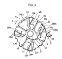
- FIG. 1 shows an overall construction of the color electrophotographic apparatus of the embodiment.
- This apparatus includes an image generation unit for forming color toner images from image signals received from an external unit, an intermediate transfer unit for forming a color image by superimposing and transferring the toner images onto paper, paper feed units 36a and 36b for supplying paper, and a fixer 44 for fixing transferred toner images onto the paper.
- the image generation unit is composed of a laser exposure unit 3 for emitting a signal light 13 for four colors in accordance with the image signals, image forming units 1 Bk, 1Y, 1 M, and 1 C forforming a latent image onto a photosensitive drum 9 by receiving the signal light 13 and furtherforming toner images of different colors.
- the image forming units 1 Bk, 1Y, 1 M, and 1C respectively for black, yellow, magenta, and cyan are all fan-shaped and arranged to form a circle as shown in FIG. 1 and placed approximately in the center of the apparatus.
- Each image forming unit is provided with a cylindrical photosensitive drum 9, a developer containing a color toner, and a cleaner.
- the image forming units 1Bk, 1Y, 1M, and 1C which are supported by a frame 151 (refer to FIGS. 4 and 5), can be rotatable around a fixed cylindrical axis 31 in the X direction.
- the rotating operations of the frame and the image forming units are driven by a motor 30.
- the motor 30 is so controlled by a control circuit 29 shown in FIG. 1 that the four image forming units can sequentially reach an image forming position 50.
- the laser exposure unit 3 is placed at a position lower than the fixed axis 31 and outside the image forming units.
- the laser exposure unit 3 generates the signal light 13 which is a laser beam modulated in accordance with image signals inputted from an external unit.
- the signal light 13 emitted from the laser exposure unit 3 goes straight to the fixed axis 31 along the wall of the cleaner which belongs to the image forming unit standing on the image forming position.
- the fixed axis 31 includes therein a diagonally downward transparent window 4 to let the signal light 13 pass through, and a long mirror 5 in the direction of the axis of the fixed axis 31.
- the signal light 13 emitted from the laser exposure unit 3 passes the window 4 and is reflected by the mirror 5, thereby leading to a predetermined position on the,surface of the photosensitive drum 9 standing on the image formation position 50.
- the exposure position stands roughly as high as the mirror 5.
- the signal light 13 proceeds diagonally upward to be reflected by the mirror 5 and proceeds in a horizontal direction to reach the exposure position.
- the intermediate transfer unit includes an intermediate transfer belt 32 as a transfer member, a drive roller 34, and a first transfer roller 33 which is positioned in accordance with the predetermined transfer position.
- the transfer position stands on the surface of the photosensitive drum 9 of the image forming unit on the image forming position 50, transfer position which faces the exposure position. In otherwords, the exposure position lies inside the image forming unit and the transfer position outside the unit on the surface of the photosensitive drum 9.
- the intermediate transfer belt 32 is made of semiconductive urethane film having a thickness of 1 OOwm, and rolled over a stainless drive roller 34 and a first transfer roller 33 made of urethane foam which has been through low resistance process, thereby rotating in the Z direction.
- the distance between the drive roller 34 and the first transfer roller 33 is so determined that the entire length of the intermediate transfer beltcan be a little bit longer than the longitudinal length of A4 size paper.
- the first transfer roller 33 is in a slight contact with the photosensitive drum 9 of the image forming unit standing on the image forming position (the unit 1 BK in FIG. 1) having the intermediate transfer belt 32 therebetween.
- the drive roller 34 is in a slight contact with a second transfer roller 35 having the intermediate transfer belt 32 therebetween.
- the second transfer roller 35 has the same construction as the first transfer roller 33 and rotates in accordance with the drive roller 34.
- the intermediate transfer unit further includes a belt cleaning unit 40 having a belt cleaner for cleaning the intermediate transfer belt 32.
- the paper feed units 36a and 36b which are placed besides the main body of the apparatus, send paper to a nipping portion between the intermediate transfer belt 32 and the second transfer roller 35.
- the paper feed unit 36a feeds paper that an operator put on the tray to the intermediate transfer unit and the paper feed unit 36b feeds paper in stock to the intermediate transfer unit.
- the fixer 44 is provided above the belt cleaning unit 40 together with a paper discharge roller 45 for discharging toner-fixed paper. There provided a path for conveying paper from the paper feed units 36a and 36b up to the fixer44 via the nipping portion. Furthermore, a lid 46 is provided above the main body of the apparatus, the lid 46 being opened for maintenance.
- each image forming unit is sequentially moved to the image forming position 50 and positioned.
- the image forming position 50 faces the first transfer roller 33 which supports the intermediate transfer belt 32.
- the photosensitive drum 9 of the unit is pressed onto the first transfer roller 33 and at the same time, is exposed at a predetermined exposure position.
- the signal light 13 emitted from the laser exposure unit 3 goes through a light path formed between adjacent image forming units, and further goes through the window4 of the fixed axis 31 to reach the mirror 5.
- the signal light 13 Being reflected by the mirror 5, the signal light 13 goes to the surface of the photosensitive drum 9 of the image forming unit which stands on the image forming position, thereby forming an electrostatic latent image onto the surface of the drum 9.
- the signal light 13 goes through the path formed between the image forming units 1 Bk and 1Y, and is reflected by the mirror 5 to reach the photosensitive drum 9 of the image forming unit 1 Bk.
- the light path for leading the signal light 13 to the mirror 5 is formed between the wall of the image forming unit standing on the image forming position 50 and the wall of a lower adjacent image forming unit.
- each radial gap between adjacent image forming units is made to be a light path, so that the area for the image forming units does not need to be so large as to make room for the light path.
- the mirror 5 is fixed in the center of the circle formed with the image forming units, so that it does not interfere with the rotating operation of the image forming units. This feature provides a simple and highly reliable construction for positioning the latent images.
- the mirror 5 is provided inside the fixed axis 31 and the light path is designed to make the reflection surface of the mirror 5 and the window 4 downward, in order to prevent dust or toner scattered around from gathering on the surface of the mirror 5 or on the window 4.
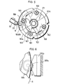
- FIG. 2 shows a sectional view of the image forming unit 1 Bk which includes the photosensitive drum 9, a charge roller 11, a developer collection roller 17, a hopper 14 containing a developing material 26Bk, and a cleaner 27.
- the photosensitive drum 9 is designed to be rotatable around the fixed axis 12 and the surface of the drum 9 is composed of an organic photosensitive member made from a polycarbonate binder resin and phthalocyanine dispersed in the polycarbonate binder resin.
- the photosensitive drum 9 has a magnet 10 fixed on the axis 12 for attracting the developing material 26Bk on the surface thereof.
- a charge roller 11 is provided in contact with the surface of the drum 9 for negatively charging the entire surface of the drum 9.
- the fan shape of the sectional view of the unit Bk1 is formed by the hopper 14 and the cleaner 27.
- the hopper 14 stands above the drum 9 and the cleaner 27 stands below the drum 9 for cleaning toner which remains on the surface of the drum 9 after every transfer operation.
- the hopper 14 and the cleaner 27 are so disposed to make a light path therebetween for leading the signal light 13 which has been reflected by the mirror 5 to the exposure position.
- the developer collection roller 17 which is rotatable around the fixed axis 17a made of aluminum, is provided very closely to the photosensitive drum 9.
- the developer collection roller 17 has a magnet 16 fixed to the axis 17a for attracting the developing material 26Bk, and the hopper 14 is provided with a scraper 19, which is made of polyester, for scraping toner gathered on the developer collection roller 17.
- the cleaner 27 is provided with a cleaning blade 20 made of urethane rubber for cleaning off toners which remain on the surface of the photosensitive drum 9.
- An AC high voltage source 18 for applying high voltage to the developer collection roller 17 is provided outside the image forming units.
- the photosensitive drum 9 whose diameter is 30mm and the developer collection roller 17 whose di- i-ameter is 16mm both rotate at a peripheral speed of 60mm/s in the direction of "W" that is shown in FIG. 2.
- the hopper 14 has two-component developing material 26Bk which is composed of a toner 25Bk and a ferrite carrier 24Bk whose surface is coated with a silicone resin.
- the particles of the ferrite carrier 24Bk is 50 ⁇ m.
- the toners used in the embodiment are made by dispersing pigments to a polyester resin and further adding an additive agent thereto.
- the photosensitive drum 9 of the unit Bk1 is charged through the charge roller 11 at -500V and then exposed to the signal light 13, thereby forming an electrostatic latent image. At this point, the exposure potential of the surface of the drum 9 is -100V. Then, the ferrite carrier 24Bk is attracted by the magnet 10 and as a result, the two-component developing material 26Bk contained in the hopper 14 is fixed onto the surface of the drum 9.
- the drum 9 having the two-component developing material 26Bk thereon passes in front of the developer collection roller 17, thereby forming a toner image onto the surface thereof as follows.
- the developer collection roller 17 When an uncharged area on the photosensitive drum 9 passes by at the beginning of a rotation, the developer collection roller 17 is applied 750Vo-p (peak to peak 1.5kV) AC voltage (1 kHz frequency), into which OV direct current has been superimposed, from the AC high voltage source 18. As a result, all the carriers and toners on the drum 9 are collected by the developer collection roller 17, leaving nothing there.
- the developer collection roller 17 After the photosensitive drum 9 is charged a voltage of -500V, when an area on the drum 9 having an electrostatic latent image thereon passes by, the developer collection roller 17 is applied 750V0-p (peak to peak 1.5kV) AC voltage (1kHz frequency), into which -350V direct current has been superimposed. As a result, carriers on the drum 9 and toners fixed on the charged area are collected by the developer collection roller 17, leaving an expected toner image on the drum 9. The carriers and toners fixed onto the developer collection roller 17 is scraped by the scraper 19 and returned to the hopper 14 to be used for the next image forming operation. Hence, a black toner image is formed on the drum 9.
- the hopper 14 containing the developing material 26Bk stands above the drum 9 and the cleaner 27 stands below the drum 9, so that developing operations and cleaning operations can be carried out smoothly without any mechanism for moving or mixing the developing material or toners.
- the other image forming units 1Y, 1 M, and 1C have the same construction and operations.
- the image forming units 1 Bk, 1Y, 1 M, and 1 C are respectively provided with the drum-covers 28Bk, 28Y, 28M, and 28C to protect its own drum 9.
- one of the covers is open for image formation.
- Each image formation unit can be detached from the main body of the apparatus when it stands in the uppermost position (at the position of the unit 1C in FIG. 1).
- the construction and operation of the drum-covers 28Bk, 28Y, 28M, and 28C and the detaching operation of the image forming unit will be detailed later.
- Each image forming unit is positioned as shown in FIG. 1, where the image forming unit 1 Bk for black stands on the image forming position 50.
- a signal light for black is emitted to the image forming unit 1 Bk by the laser exposure unit 3, to form a black image by a black toner.
- the image forming speed of the image forming unit 1 Bk (identical to the peripheral speed of the photosensitive drum 9) and the transfer speed of the intermediate transfer belt 32 are set to be equal.
- a black toner image formed on the drum 9 is transferred onto the intermediate transfer belt 32 through the first transfer roller 33 which is applied a positive voltage during a transfer operation.
- the image forming units 1Bk, 1Y, 1M, and 1C rotate 90 degrees in the direction of X by the transfer motor 30 until the unit 1Y reaches the image forming position 50.
- the position of the unit 1Y is fixed by a positioning mechanism which will be described later.
- the intermediate transfer belt 32 does not touch the unit 1 Y during a rotating operation.
- the laser exposure unit 3 sends a signal light for yellow to the unit 1Yto form and transfer a yellow image in the same manner as the black image.
- the timing of exposing the yellow signal light is so controlled that the yellow toner image is successfully superimposed on the black toner image when the intermediate transfer belt 32 has made a round.
- the second transfer roller 35 and the belt cleaning unit40 are put away from the intermediate transfer belt 32, giving no effect on the toner image.
- a single color mode In a single color mode, one image forming unit for a desired color is transferred to the image forming position and positioned. Then, a desired-color image is formed and transferred onto the intermediate transfer belt 32 in the same manner as above, and the transfer operation is continued with paper which is sent from the paper feed units 36a or 36b through the second transfer roller 35.
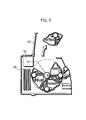
- FIG. 3 is a sectional view of the opening and closing mechanism of the drum-covers provided at one side of the image forming units when it is viewed from the same direction as FIG. 1. Each image forming unit is put in the same position as in FIG. 1.
- Each of the drum-covers 28Bk, 28Y, 28M, and 28C is supported by the pivotable levers 47 and 48 attached at a side of the image forming unit.
- the drum-cover 28C protects the drum 9 with the support of the spring 49C as indicated with the full line.
- the lever 47C is rotated in the left direction, the drum-cover 28C traces the arcs indicated with the dashed lines and the drum-cover 28C reaches a pit 51C on the outer surface of the unit 1 C.
- the drum-cover 28C is placed as indicated with the two dashed line 28Ca.
- the drum-cover 28 which is thus designed to be openable, can be open on the image forming position by providing the cam mechanism including a cam 52 as follows.
- the shape of the cam 52 which is fixed to the fixed axis 31, allows the drum-cover 28Bk to be put into the pit 51 by pressing the lever 47 while the image forming unit 1 Bk is passing by the first transfer roller 33.
- the cam 52 does not work on the levers 47Y, 47M, and 47C for the units 1Y, 1 M and 1C respectively that are not on the image forming position.
- the drum-covers 28Y, 28M, and 28C are closed by the support of the springs 49Y, 49M, and 49C respectively.
- each of the image forming units rotating in the X direction opens its own drum-cover before it reaches the image forming position and closes the drum-cover leaving the position.
- the drum-covers are put in the pit 51, they are positioned inside of the outermost arc drawn by the photosensitive drums 9 (indicated by two-dashed line 53 in FIG. 3). Therefore the drum-covers do not touch the intermediate transfer belt 32 during the rotation of the image forming units.
- each image forming unit is designed to be slightly movable toward the center of the frame 151 and energized in an outer direction by the springs 158 and 159. Each image forming unit is detachable from the frame 151.
- the clutch 160 can connect and disconnect the driving force between the two gears 164 and 165 according to an external signal.
- the other clutches than the clutch 160 are not shown in FIG. 4 to make the drawing simple.
- the gear 165 of the clutch 160 is engaged with the drum gear 154Bk and the other gear 164 is engaged with the gear 167 which works cooperatively with the fly wheel 166. Accordingly, when the clutch 160 is connected, the driving force of the fly wheel 166 is conveyed to the drum 9, and otherwise the driving force is suspended.
- each image forming unit is slightly movable toward the center of the frame 151 and also energized in an outer direction by the springs 158 and 159, in the process of forming a color image the collar 169b goes up a slope of the positioning stand 170b until it is engaged with the V-shape groove. In this state, the image forming unit in the V-shape groove stands back toward the center of the rotation, as compared with the other image forming units.
- the fly wheel 166a serves to transfer the driving force with very little fluctuation to the photosensitive drum 9 of the image forming unit in process of image formation. As a result, clear toner images with little jittering, which is caused by rotating fluctuation, can be obtained.
- the operator can replace the outstanding image forming unit with another by opening the lid 46, without touching the photosensitive drum 9 because the drum-cover is closed.
- an image forming operation can be resumed without any adjustment after the image forming unit is attached.
- the four toner images are all formed on the same position and then all transferred onto the same position, so that the toner images of different colors can be superimposed accurately.
- the image forming units are independent of each other and can be replaced by a new one separately with ease, or repaired outside of the apparatus.
- To arrange the fan-shaped image forming units in the form of a circle can eliminate wasteful space, using a gap between adjacent image forming units as a light path, thereby minimizing the image forming units.
- the attaching or detaching operation of the image forming units does not spoil their photosensitive drums 9 because they are protected with the drum-covers 28. Furthermore, the image forming units that are not standing on the image forming position are protected with the drum-covers 28, so that their photosensitive drums 9 are protected from dust or toners.
- the mirror 5 is provided inside the fixed axis 31 and the light path is designed to make the reflection surface of the mirror 5 and the window 4 downward, so that the surface of the mirror 5 and the window 4 can be kept away from dust or toner scattered.
- the photosensitive drum 9 of the image forming unit in process of forming images is driven by the gear 167 which is directly connected with the fly wheel 166, the drum 9 can rotate smoothly with very little fluctuation.
- clear color toner images with little jittering can be obtained from the single fly wheel.
- toner images formed on the photosensitive member are transferred onto the intermediate transfer belt of the intermediate transfer unit, and then transferred onto paper all at once.
- an intermediate transfer drum can be used instead of the intermediate transfer belt, or the toner images can be transferred from the photosensitive member to the paper which is rolled over the transfer drum.
Landscapes
- Physics & Mathematics (AREA)
- General Physics & Mathematics (AREA)
- Color Electrophotography (AREA)
Applications Claiming Priority (8)
| Application Number | Priority Date | Filing Date | Title |
|---|---|---|---|
| JP5178998A JPH0736246A (ja) | 1993-07-20 | 1993-07-20 | カラー電子写真装置 |
| JP17899393A JP3323288B2 (ja) | 1993-07-20 | 1993-07-20 | カラー画像記録装置 |
| JP178993/93 | 1993-07-20 | ||
| JP178998/93 | 1993-07-20 | ||
| JP5184976A JPH0743972A (ja) | 1993-07-27 | 1993-07-27 | カラー電子写真装置および像形成ユニット |
| JP184976/93 | 1993-07-27 | ||
| JP186041/93 | 1993-07-28 | ||
| JP5186041A JPH0743976A (ja) | 1993-07-28 | 1993-07-28 | カラー電子写真装置 |
Publications (3)
| Publication Number | Publication Date |
|---|---|
| EP0635764A2 true EP0635764A2 (de) | 1995-01-25 |
| EP0635764A3 EP0635764A3 (de) | 1995-03-29 |
| EP0635764B1 EP0635764B1 (de) | 1998-10-07 |
Family
ID=27474860
Family Applications (1)
| Application Number | Title | Priority Date | Filing Date |
|---|---|---|---|
| EP94305246A Expired - Lifetime EP0635764B1 (de) | 1993-07-20 | 1994-07-18 | Elektrofotografisches Farbgerät und in ihm verwendete Bilderzeugungseinheit |
Country Status (3)
| Country | Link |
|---|---|
| US (1) | US5610701A (de) |
| EP (1) | EP0635764B1 (de) |
| DE (1) | DE69413758T2 (de) |
Cited By (2)
| Publication number | Priority date | Publication date | Assignee | Title |
|---|---|---|---|---|
| EP0902334A3 (de) * | 1993-09-16 | 1999-07-14 | Matsushita Electric Industrial Co., Ltd | Elektrophotographisches Farbgerät und Bilderzeugungseinheit |
| EP1712957A1 (de) * | 2005-04-15 | 2006-10-18 | Samsung Electronics Co, Ltd | Entwicklereinheit für einen Drucker mit einem Spiegel |
Families Citing this family (10)
| Publication number | Priority date | Publication date | Assignee | Title |
|---|---|---|---|---|
| US5809380A (en) * | 1996-03-14 | 1998-09-15 | Matsushita Electric Industrial Co., Ltd. | Color image forming apparatus with plural color units |
| US5956552A (en) * | 1996-09-24 | 1999-09-21 | Matsushita Electric Industrial Co., Ltd. | Color image forming apparatus comprising a regular mode and a high speed mode |
| JPH10133450A (ja) | 1996-11-05 | 1998-05-22 | Matsushita Electric Ind Co Ltd | カラー画像形成装置 |
| JPH117173A (ja) * | 1997-06-16 | 1999-01-12 | Matsushita Electric Ind Co Ltd | カラー画像形成装置 |
| KR100238037B1 (ko) * | 1997-06-16 | 2000-01-15 | 윤종용 | 다색화상 형성장치의 현상장치 및 그 제어방법 |
| US6546220B1 (en) | 1998-08-28 | 2003-04-08 | Matsushita Electric Industrial Co., Ltd. | Image forming apparatus with plural color image forming units moveable into image forming position |
| US6397016B1 (en) * | 1999-06-28 | 2002-05-28 | Matsushita Electric Industrial Co., Ltd. | Image forming apparatus having a plurality of image forming units and translucent toner detection window |
| US6408155B1 (en) | 1999-10-08 | 2002-06-18 | Matsushita Electric Industrial Co., Ltd. | Color printing device |
| US6397029B1 (en) | 2001-01-11 | 2002-05-28 | Lexmark International, Inc | Coupler for an image-forming apparatus |
| KR100503801B1 (ko) * | 2003-07-24 | 2005-07-26 | 삼성전자주식회사 | 컬러 전자사진방식 인쇄기 |
Family Cites Families (13)
| Publication number | Priority date | Publication date | Assignee | Title |
|---|---|---|---|---|
| JPS5918450Y2 (ja) * | 1976-05-17 | 1984-05-28 | 富士ゼロツクス株式会社 | 電子複写機の現像装置 |
| JPS56122049A (en) * | 1980-02-29 | 1981-09-25 | Toshiba Corp | Electronic copier |
| US4743938A (en) * | 1984-10-16 | 1988-05-10 | Canon Kabushiki Kaisha | Color image forming apparatus |
| JPH0679171B2 (ja) * | 1984-12-26 | 1994-10-05 | キヤノン株式会社 | 画像形成装置 |
| JPH0682235B2 (ja) * | 1986-06-05 | 1994-10-19 | キヤノン株式会社 | カラー画像形成装置 |
| US4975741A (en) * | 1986-09-11 | 1990-12-04 | Fuji Xerox Co., Ltd. | Control unit for a copying machine including automatic shutdown |
| JPH01250970A (ja) * | 1988-03-31 | 1989-10-05 | Canon Inc | 画像形成装置 |
| JPH01252982A (ja) * | 1988-04-01 | 1989-10-09 | Canon Inc | 転写装置 |
| JPH0786714B2 (ja) * | 1989-01-09 | 1995-09-20 | シャープ株式会社 | フルカラー複写装置 |
| JP2983310B2 (ja) * | 1991-01-29 | 1999-11-29 | 株式会社リコー | 画像形成装置の回転型現像装置 |
| JP2595824B2 (ja) * | 1991-02-01 | 1997-04-02 | 富士ゼロックス株式会社 | 画像形成用カートリッジ |
| US5351115A (en) * | 1991-05-23 | 1994-09-27 | Matsushita Electric Industrial Co., Ltd. | Color electrophotographic method and apparatus employed therefor |
| JP3187522B2 (ja) * | 1992-04-30 | 2001-07-11 | 株式会社リコー | 回転型現像装置を用いた画像形成装置 |
-
1994
- 1994-07-18 US US08/276,704 patent/US5610701A/en not_active Expired - Fee Related
- 1994-07-18 EP EP94305246A patent/EP0635764B1/de not_active Expired - Lifetime
- 1994-07-18 DE DE69413758T patent/DE69413758T2/de not_active Expired - Fee Related
Cited By (3)
| Publication number | Priority date | Publication date | Assignee | Title |
|---|---|---|---|---|
| EP0902334A3 (de) * | 1993-09-16 | 1999-07-14 | Matsushita Electric Industrial Co., Ltd | Elektrophotographisches Farbgerät und Bilderzeugungseinheit |
| EP0644465B1 (de) * | 1993-09-16 | 1999-12-01 | Matsushita Electric Industrial Co., Ltd. | Elektrophotographisches Farbgerät und Verfahren zur Durchführung in einem solchen Gerät |
| EP1712957A1 (de) * | 2005-04-15 | 2006-10-18 | Samsung Electronics Co, Ltd | Entwicklereinheit für einen Drucker mit einem Spiegel |
Also Published As
| Publication number | Publication date |
|---|---|
| DE69413758T2 (de) | 1999-03-25 |
| US5610701A (en) | 1997-03-11 |
| EP0635764A3 (de) | 1995-03-29 |
| EP0635764B1 (de) | 1998-10-07 |
| DE69413758D1 (de) | 1998-11-12 |
Similar Documents
| Publication | Publication Date | Title |
|---|---|---|
| EP1195652B1 (de) | Elektrophotographisches Farbgerät | |
| EP0635764B1 (de) | Elektrofotografisches Farbgerät und in ihm verwendete Bilderzeugungseinheit | |
| EP0639801B1 (de) | Farbbilderzeugungsgerät mit Prozesseinheit und Farbentwicklungskartusche | |
| JP3249655B2 (ja) | カラー画像記録装置 | |
| JP3380531B2 (ja) | カラー画像記録装置 | |
| JP3061739B2 (ja) | カラー画像記録装置 | |
| JP3231037B2 (ja) | カラー画像記録装置 | |
| JP3227150B2 (ja) | カラー画像記録装置 | |
| JP3227149B2 (ja) | カラー画像記録装置 | |
| JP3066759B2 (ja) | カラー画像形成装置 | |
| JP3369541B2 (ja) | カラー画像記録装置 | |
| JP3323288B2 (ja) | カラー画像記録装置 | |
| JP3265295B2 (ja) | カラー画像記録装置 | |
| JP3163086B1 (ja) | カラー画像記録装置 | |
| JP2001051474A (ja) | トナーカートリッジ収容体 | |
| JP2000172035A (ja) | カラ―画像記録装置 | |
| JP2001056591A (ja) | カラー画像記録装置 | |
| JPH0743976A (ja) | カラー電子写真装置 | |
| JPH07219300A (ja) | カラー電子写真装置 | |
| JP2001056589A (ja) | カラー画像記録装置 | |
| JP2003076091A (ja) | 画像形成装置 | |
| JPH07219294A (ja) | カラー電子写真装置 | |
| JPH0792759A (ja) | カラー電子写真装置 | |
| JP2001249520A (ja) | カラー画像記録装置 | |
| JP2001249514A (ja) | カラー画像記録装置 |
Legal Events
| Date | Code | Title | Description |
|---|---|---|---|
| PUAI | Public reference made under article 153(3) epc to a published international application that has entered the european phase |
Free format text: ORIGINAL CODE: 0009012 |
|
| AK | Designated contracting states |
Kind code of ref document: A2 Designated state(s): DE FR GB |
|
| PUAL | Search report despatched |
Free format text: ORIGINAL CODE: 0009013 |
|
| AK | Designated contracting states |
Kind code of ref document: A3 Designated state(s): DE FR GB |
|
| 17P | Request for examination filed |
Effective date: 19950922 |
|
| 17Q | First examination report despatched |
Effective date: 19970305 |
|
| GRAG | Despatch of communication of intention to grant |
Free format text: ORIGINAL CODE: EPIDOS AGRA |
|
| GRAG | Despatch of communication of intention to grant |
Free format text: ORIGINAL CODE: EPIDOS AGRA |
|
| GRAG | Despatch of communication of intention to grant |
Free format text: ORIGINAL CODE: EPIDOS AGRA |
|
| GRAH | Despatch of communication of intention to grant a patent |
Free format text: ORIGINAL CODE: EPIDOS IGRA |
|
| GRAH | Despatch of communication of intention to grant a patent |
Free format text: ORIGINAL CODE: EPIDOS IGRA |
|
| GRAA | (expected) grant |
Free format text: ORIGINAL CODE: 0009210 |
|
| AK | Designated contracting states |
Kind code of ref document: B1 Designated state(s): DE FR GB |
|
| REF | Corresponds to: |
Ref document number: 69413758 Country of ref document: DE Date of ref document: 19981112 |
|
| ET | Fr: translation filed | ||
| PLBE | No opposition filed within time limit |
Free format text: ORIGINAL CODE: 0009261 |
|
| STAA | Information on the status of an ep patent application or granted ep patent |
Free format text: STATUS: NO OPPOSITION FILED WITHIN TIME LIMIT |
|
| 26N | No opposition filed | ||
| REG | Reference to a national code |
Ref country code: GB Ref legal event code: IF02 |
|
| PGFP | Annual fee paid to national office [announced via postgrant information from national office to epo] |
Ref country code: FR Payment date: 20050708 Year of fee payment: 12 |
|
| PGFP | Annual fee paid to national office [announced via postgrant information from national office to epo] |
Ref country code: GB Payment date: 20050713 Year of fee payment: 12 |
|
| PG25 | Lapsed in a contracting state [announced via postgrant information from national office to epo] |
Ref country code: GB Free format text: LAPSE BECAUSE OF NON-PAYMENT OF DUE FEES Effective date: 20060718 |
|
| GBPC | Gb: european patent ceased through non-payment of renewal fee |
Effective date: 20060718 |
|
| REG | Reference to a national code |
Ref country code: FR Ref legal event code: ST Effective date: 20070330 |
|
| PGFP | Annual fee paid to national office [announced via postgrant information from national office to epo] |
Ref country code: DE Payment date: 20070712 Year of fee payment: 14 |
|
| PG25 | Lapsed in a contracting state [announced via postgrant information from national office to epo] |
Ref country code: FR Free format text: LAPSE BECAUSE OF NON-PAYMENT OF DUE FEES Effective date: 20060731 |
|
| PG25 | Lapsed in a contracting state [announced via postgrant information from national office to epo] |
Ref country code: DE Free format text: LAPSE BECAUSE OF NON-PAYMENT OF DUE FEES Effective date: 20090203 |