EP0701316A2 - Betätiger mit drehender und translatorischer Bewegung - Google Patents
Betätiger mit drehender und translatorischer Bewegung Download PDFInfo
- Publication number
- EP0701316A2 EP0701316A2 EP95300183A EP95300183A EP0701316A2 EP 0701316 A2 EP0701316 A2 EP 0701316A2 EP 95300183 A EP95300183 A EP 95300183A EP 95300183 A EP95300183 A EP 95300183A EP 0701316 A2 EP0701316 A2 EP 0701316A2
- Authority
- EP
- European Patent Office
- Prior art keywords
- grip
- coil
- piston
- rotary actuator
- housing
- Prior art date
- Legal status (The legal status is an assumption and is not a legal conclusion. Google has not performed a legal analysis and makes no representation as to the accuracy of the status listed.)
- Granted
Links
Images





Classifications
-
- H—ELECTRICITY
- H02—GENERATION; CONVERSION OR DISTRIBUTION OF ELECTRIC POWER
- H02K—DYNAMO-ELECTRIC MACHINES
- H02K41/00—Propulsion systems in which a rigid body is moved along a path due to dynamo-electric interaction between the body and a magnetic field travelling along the path
- H02K41/02—Linear motors; Sectional motors
- H02K41/03—Synchronous motors; Motors moving step by step; Reluctance motors
- H02K41/031—Synchronous motors; Motors moving step by step; Reluctance motors of the permanent magnet type
-
- H—ELECTRICITY
- H02—GENERATION; CONVERSION OR DISTRIBUTION OF ELECTRIC POWER
- H02K—DYNAMO-ELECTRIC MACHINES
- H02K41/00—Propulsion systems in which a rigid body is moved along a path due to dynamo-electric interaction between the body and a magnetic field travelling along the path
- H02K41/02—Linear motors; Sectional motors
- H02K41/035—DC motors; Unipolar motors
-
- H—ELECTRICITY
- H02—GENERATION; CONVERSION OR DISTRIBUTION OF ELECTRIC POWER
- H02K—DYNAMO-ELECTRIC MACHINES
- H02K41/00—Propulsion systems in which a rigid body is moved along a path due to dynamo-electric interaction between the body and a magnetic field travelling along the path
- H02K41/02—Linear motors; Sectional motors
- H02K41/035—DC motors; Unipolar motors
- H02K41/0352—Unipolar motors
- H02K41/0354—Lorentz force motors, e.g. voice coil motors
- H02K41/0356—Lorentz force motors, e.g. voice coil motors moving along a straight path
-
- H—ELECTRICITY
- H02—GENERATION; CONVERSION OR DISTRIBUTION OF ELECTRIC POWER
- H02K—DYNAMO-ELECTRIC MACHINES
- H02K2201/00—Specific aspects not provided for in the other groups of this subclass relating to the magnetic circuits
- H02K2201/18—Machines moving with multiple degrees of freedom
-
- Y—GENERAL TAGGING OF NEW TECHNOLOGICAL DEVELOPMENTS; GENERAL TAGGING OF CROSS-SECTIONAL TECHNOLOGIES SPANNING OVER SEVERAL SECTIONS OF THE IPC; TECHNICAL SUBJECTS COVERED BY FORMER USPC CROSS-REFERENCE ART COLLECTIONS [XRACs] AND DIGESTS
- Y10—TECHNICAL SUBJECTS COVERED BY FORMER USPC
- Y10T—TECHNICAL SUBJECTS COVERED BY FORMER US CLASSIFICATION
- Y10T29/00—Metal working
- Y10T29/49—Method of mechanical manufacture
- Y10T29/49002—Electrical device making
- Y10T29/49117—Conductor or circuit manufacturing
- Y10T29/49124—On flat or curved insulated base, e.g., printed circuit, etc.
- Y10T29/4913—Assembling to base an electrical component, e.g., capacitor, etc.
- Y10T29/49133—Assembling to base an electrical component, e.g., capacitor, etc. with component orienting
Definitions
- the present invention pertains generally to machines which are useful for the automated assembly of products. More specifically, the present invention pertains to apparatus and devices which are useful for inspecting, assembling and positioning component parts in a product assembly process.
- the present invention is particularly, but not exclusively, useful as an apparatus for the quick movement and precise positioning of relatively fragile component parts, in an appropriate translational and rotational alignment, during an automated assembly procedure while generating both extremely light forces and normal forces on the component parts.
- stepper-motor systems can be spatially precise in their operation, and the forces which they generate can be effectively controlled.
- Stepper-motors are bulky items and do not have good light force generation characteristics. In some manufacturing procedures these factors can be of significant disadvantage.
- Pneumatic devices are not known for performing with high precision, primarily because of their damping characteristics. However, they are sometimes suitable for achieving some modes of motion in a precision device.
- the present invention has recognized that an electronically operated system can be effective for the precise placement of a product component during assembly without encountering the force and spatial problems confronted by the above discussed types of systems.
- the present invention also recognizes that, in some applications of a precision transporter apparatus, the rotational mode of motion can be adequately and economically accomplished by the use of a pneumatically driven rotary actuator. More specifically, the present invention recognizes that a voice coil linear motor can be applied for these purposes, and that a pneumatic rotary actuator can be coupled with the voice coil linear motor, to accomplish certain high tolerance rotational motion.
- the present invention also recognizes there are instances when it is important that a work product be both precisely moved in a translational motion, and oriented rotationally, but with a higher degree of tolerance. Further, there are instances when it is necessary for the work product to be rotated to join the work product to another component such as when it is necessary to thread or screw one component into another.
- an electronic system has other characteristics which can be advantageous for a device which is to be used in the automated assembly of an end product. For example, some electronic system can rather easily lend itself to compact configurations. Further, an electronic system is responsive and can be configured to provide signals which can be used to monitor and control the operation of the system.
- An apparatus for transporting and positioning a workpiece in an automated assembly procedure includes a housing, with a magnet fixedly mounted on the housing to establish a magnetic field within the housing.
- the magnet is preferably a rare earth magnet and is formed with a projection that extends through the central chamber of the housing.
- a coil piston formed with an open passageway, is slidingly mounted on the housing and is positioned to surround the magnet with the projection of the magnet extending through the passageway.
- a plurality of magnets can be mounted on the housing and the coil piston can be slidingly mounted on the housing for reciprocation in the magnetic field between the magnets. In either case, a conductive wire is wrapped around the coil piston to create a coil assembly.
- the apparatus also includes a grip which is mounted on the coil piston to hold the workpiece or product component during its transfer from a supply source into position for product assembly.
- the grip is a hollow rod which is mounted on the coil piston for linear movement with the coil piston and for rotation on the coil piston about the longitudinal axis of the rod.
- the grip can have an end piece which is operable to grasp the workpiece or component to be moved.
- a vacuum source can be operatively connected with the rod to create a suction through the hollow rod that holds the workpiece or product component against the rod during transport.
- the rod is rotatably mounted within a sleeve, with the vacuum being applied to the interior of the rod via the sleeve.
- the sleeve is sealed against the piston, and the rod is sealed against the sleeve, to prevent vacuum leakage.
- a source of electrical current is provided and is connected directly to the coil of the coil assembly. Electrical currents from this source are passed through the coil as desired by the operator. Because the coil is disposed in the magnetic field that is generated by the magnet, current flow through the coil creates a force on the coil piston. This force then moves the coil piston and the grip relative to the housing. Additionally, the apparatus itself can be moved in any manner well known in the art, and the concerted action of apparatus movement and the movement of the grip relative to the rest of the apparatus can be used to transport a workpiece or a product component from one location to another.
- a position sensor can be mounted on the housing of the apparatus to detect the location of the coil piston, and hence the translation position of the grip, relative to the housing.
- the sensor can be either a relatively uncomplicated capacitive type sensor or, preferably, a more sophisticated optical encoder.
- the translational position sensor can be used to calibrate movement of the grip and to establish its start and stop points.
- signals generated by the translational position sensor can be used to control the operation and translational movement of the coil piston and to inspect the result of the operation of the apparatus.
- the apparatus can be modified to include a microprocessor which compares the actual position of the coil piston (as indicated by the position sensor) with a preset desired position of the coil piston (in accordance with programmed input).
- This comparison will generate an error signal.
- control of the coil piston can be accomplished by moving the coil piston in a manner which will reduce the error signal to zero. This, of course, is done if control is the objective. On the other hand, if inspection and quality control are the objectives, the error signal can be maintained and the assembled product rejected if the error signal exceeds the established tolerance.
- the apparatus provides for both translational and rotational control over both the movement and positioning of the product component.
- the intent here may be not only to properly align the product component, but to also provide for the capability of screwing or threading the product component into another component of the product being assembled.
- one embodiment of the present invention includes a pneumatic rotary actuator which is mounted on the coil piston for translational movement with the coil piston.
- the output shaft of the rotary actuator is connected to the grip of the apparatus by a coupling, to cause rotation of the grip upon activation of the rotary actuator. Where a vacuum grip is used, the vacuum passage is sealed while still allowing relative rotation of the grip.
- An encoder is also provided which is positioned to detect the angular displacement of the grip relative to a predetermined reference. More specifically, an encoder wheel is attached to the grip rod and an optical encoder is mounted on the coil piston.
- the microprocessor is electronically connected to the optical encoder and uses signals generated by the optical encoder to ascertain the angular position of the grip rod. In accordance with signals from the microprocessor, the rotary actuator is actuated to rotate the grip rod.
- signals from the microprocessor can be used to rotationally orient the product component. Further, in accordance with predetermined instructions concerning number of rotations or allowable torque limits, signals from the microprocessor can be used to rotate the product component to thread or screw the work component into another component.
- the apparatus of the present invention for moving and positioning an assembly component in an automated assembly operation, is shown in its intended environment and is designated 11.
- the device 11 is operatively mounted on an automated assembly machine 12 for movement between a position wherein the device (designated 11) retrieves a component 14 from a conveyor 16 and transports the component 14 to a position wherein the device (designated 11') places the component 14 into engagement with another end product component 18.
- the combination of components 14 and 18 is then taken by a conveyor 20 to a subsequent workstation where it is packaged or further combined with other components (not shown).
- the machine 12 shown in Figure 1 is only exemplary. Indeed, the device 11 can be mounted on a variety of machines (not shown) for movement between a plurality of preselected positions.
- the device 11 includes a housing 22 which is relatively compact, and is configured and dimensioned to be comparatively flat. Importantly, though not shown in the Figures, this configuration allows the device 11 to be easily stacked with other such devices for improved efficiency in an automated assembly operation.
- Figure 2 also shows that a grip (or rod) 24 is mounted on the housing 22.
- the rod 24 is preferably an elongated tubular member which is slidingly mounted on the housing 22 and which extends through the housing 22 substantially as shown.
- the housing 22 is provided with an attachment 26, and with an electrical connector 28 and a sensor connector 30.
- the rod 24 is slidingly mounted on the housing 22 between the attachment 26 and a bearing 27 (see Figure 4) which is located on the housing 22 opposite from the attachment 26. Further, as so mounted, the rod 24 can be rotated about its longitudinal axis if desired.
- FIG. 1 the present invention is shown and generally designated 100.
- This embodiment of apparatus 100 includes an electrical coil 102 which is shown here to be in a substantially flattened configuration.
- the actual shape of coil 102 is of minimal importance and will in large part be determined by the desires of the manufacturer.
- coil 102 could have been shown to be cylindrically configured. In any case, the windings of coil 102 must somehow be configured to surround a hollow space.
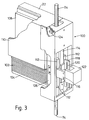
- Figure 3 shows the coil 102 wrapped around an extension 104 of a coil piston 106.
- this embodiment of apparatus 100 shows a particular structure around which the coil 102 is wrapped, the skilled artisan will appreciate that coils are commercially available which do not require such structure. Such coils may, of course, be used with the present invention. Regardless, it is important that the coil 102 be physically attached to the coil piston 106 and able to move with the coil piston 106. Further, it is important for the present invention that the grip 24 be operatively attached to the coil piston 106 and able to move with the coil piston 106.
- a magnet 108 is shown attached to the housing 22 of apparatus 100 and a magnet return 110 is also shown attached to the housing 22 and distanced from the magnet 108 so that an effective flux field is established as the environment for the coil 102.
- magnet 108 is a rare earth magnet having a permanent magnetic capability of 35 MEG oersted.
- the coil 102 may either surround the magnet 108 or, as discussed below for an alternate embodiment of the invention, the coil 102 may be positioned for movement between a plurality of magnets. This establishes a cooperation between the coil 102, the magnet 108 and the magnet return 110 in which a portion of the coil 102 is able to move between the magnet 108 and the magnet return 110.
- the coil piston 106 is fixedly attached to a linear bearing 112 and the linear bearing 112 is slidingly mounted on a bearing rail 114.
- the bearing rail 114 is fixedly mounted to the housing 22.
- This arrangement allows the linear bearing 112 with its attached coil piston 106 and coil 102 to slidingly move within the housing 22. Consequently, because the windings of coil 102 are oriented substantially perpendicular to the flux field generated by the magnet 108, the application of an electrical current to the coil 102 will generate a force on the coil piston which causes the coil assembly (i.e. coil 102 and coil piston 106) to move within housing 22. This movement needs to be monitored and controlled.
- Control over the movement of coil 102, and thus control over the grip 24, is achieved by monitoring the position of coil piston 106 relative to the housing 22. This is done using an encoder 122, such as a model SRL 4 encoder manufactured by Dynamics Research Corporation which is fixedly attached to the housing 22. More specifically, for apparatus 100, a bracket 116 is fixedly attached to linear bearing 112 and a glass encoder slide 118, with a scale 120 etched or printed thereon, is fixedly attached to the bracket 116. Accordingly, glass encoder slide 116 moves together with both linear bearing 112 and coil piston 106.
- an encoder 122 such as a model SRL 4 encoder manufactured by Dynamics Research Corporation which is fixedly attached to the housing 22. More specifically, for apparatus 100, a bracket 116 is fixedly attached to linear bearing 112 and a glass encoder slide 118, with a scale 120 etched or printed thereon, is fixedly attached to the bracket 116. Accordingly, glass encoder slide 116 moves together with both linear bearing 112 and coil piston 106.
- the apparatus 100 uses information from the encoder 122 regarding the position of glass slide 118 to precisely fix the position of coil piston 106, and thus the position of grip 24, relative to housing 22. Using this arrangement, accuracies on the order of five hundredths of a millimeter (0.05 mm) have been attained for determining the actual position of rod 24.
- rod 24 can have a magnet (not shown) which is mounted on the rod 24 for movement therewith.
- Another magnet 124, shown fixedly mounted on the housing 22 is electrically activated to magnetically engage with the magnet on rod 24 to hold the rod 24 and its associated coil assembly in a detent or withdrawn configuration during the idle time for the apparatus 100. The position of either the magnet on rod 24 or the magnet 124 can be adjusted to allow proper engagement of the rod 24 with the housing 22 in the detent position for rod 24.
- the device 11 includes a bobbin 32 (similar to coil piston 106) which is formed with a hollow 34.
- the bobbin 32 is relatively flat, like housing 22, and is generally box shaped.
- the bobbin 32 is slidingly attached to a slide mechanism 36 which is itself fixedly attached to the housing 22.
- this mechanism 36 is a very light precision way which creates minimal friction forces during movement of the bobbin 32.
- the mechanism 36 can be established in any of several ways, all known in the pertinent art, and can be provided with travel stops which will limit the distance through which bobbin 32 can travel along the mechanism 36.
- the extent of this travel is in the range of between two and four inches (2-4 inches). Consequently, the bobbin 32 is able to slide freely along the mechanism 36 and to reciprocate within the housing 22 through this distance. It is also important to recognize that the grip 24 is attached to the bobbin 32 for linear movement with the bobbin 32.
- Figure 4 also shows that a magnet 38 is mounted inside the housing 22.
- the magnet 38 is formed with a projection 40 and is positioned inside the housing 22 so that the projection 40 of magnet 38 extends into the hollow 34 of the bobbin 32.
- the magnet 38 is of a commercially available type which is made of a rare earth element.
- a Neodenium 35 megagaussoersted magnet is suitable for use in the present invention.
- the magnet 38 be a permanent magnet which is capable of operating with a magnetic intensity on the order of approximately thirty-five MEG oersted (35 MOe).
- poles of magnet 38 can be oriented on the housing 22 to effectively establish a magnetic field having flux lines that are aligned substantially perpendicular to the directions along which the bobbin 32 reciprocates in the housing 22.
- the device 11 also includes a coil 42 which is made from an electrical wire 44 that is wound around the bobbin 32.
- the winding of coil 42 around the bobbin 32 should be sufficiently tight to effectively join coil 42 to the bobbin 32.
- the ends 44a and 44b of the electrical wire 44 are electrically attached to the connector 28 so that an external voltage source 46 (shown in Figure 7) can be used to energize the coil 42.
- an external voltage source 46 shown in Figure 7
- the force which is generated on the bobbin 32 can be controlled.
- the magnitude of the forces generated on the bobbin 32 will be in a range from zero to ten thousand grams (0-10000 grams).
- the device 11 ( Figures 2 and 4) as well as the apparatus 100 ( Figure 3) will likely operate in a range where approximately zero to two thousand grams (0-2,000 gm) variable of force are selectively applied with a deviation of only plus or minus one gram ( ⁇ 1 gm).
- the position and direction of travel of the bobbin 32 can be controlled by the magnitude and direction of flow of current through the coil 42.
- a sensor 48 is incorporated into the device 11 and is operatively connected through a line 50 to the sensor connector 30 located on housing 22 of device 11. Further, line 50 completes the connection between sensor connector 30 and microprocessor 70.
- the position sensing function can be accomplished using a capacitance inductance (LVDT) sensor like the one shown in Figure 5.
- LVDT capacitance inductance
- the device 11 can include a middle plate 52 which is fixedly mounted to the bobbin 32 for movement with the bobbin 32 in the housing 22.
- This middle plate 52 is then disposed between a plate 54 and a plate 56 which are each fixedly connected to the housing 22 of device 11. Further, the plates 54 and 56 are respectively connected to lines 58 and 60 which, together, constitute the line 50 in this embodiment. Consequently, as middle plate 52 moves with the bobbin 32, the electrical capacitance between the plate 54 and 56 will be changed. This change in capacitance can be determined by the sensor 48 by means well known in the art to ascertain the position of the bobbin 32 relative to the housing 22.
- the flat plates remove concentricity problems and, as they are located away from the coil [a heat source], the sensor will be accurate.
- the capacitive elements comprising the plates 52, 54 and 56 are removed and, instead, a photo-electric system much like the encoder 122 previously discussed in conjunction with the apparatus 100 is incorporated.
- a scale 62 is fixedly attached to the housing 22 and, as indicated by cross-referencing Figures 5 and 6, the scale 62 is generally located in the same position as was the plate 54 in the embodiment previously disclosed for the sensor 48.
- a photoelectric detector 64 is fixedly mounted on the bobbin 32 for movement therewith.
- the detector 64 can include photodiode elements 66 and 68 which, either individually or collectively, will interact optically with the scale 62, in a manner well known in the pertinent art, to provide information about the position of the bobbin 32 relative to the housing 22.
- one of the preferred embodiments of the present invention includes components which allow for both translational and rotational control over a work component 14 which is being moved by the rod/grip 24.
- a magnet 108 is mounted in the housing 22 and a coil 102 is disposed in the magnetic field established by the magnet 108.
- the coil 102 is fixedly attached to a coil piston 106 so that the coil piston 106 moves with coil 102 under the influences of forces which are generated on the coil in the magnetic field as a current is passed through the coil 102.
- Figure 9 also shows that a casing 200 is attached to the coil piston, and that the casing 200 is slidably attached to housing 22. This attachment between casing 200 and housing 22 is established through the interaction of bearings 112' on casing 200 with bearing rail 114' on housing 22. It is also shown in Figure 9 that the rod/grip 24 is rotatably mounted on the casing 200 for translational motion with the casing 200 and coil piston 106. Additionally, an electrical servo motor 202, of any type well known in the pertinent art, is mounted in casing 200 for translational movement with coil piston 106.
- the electrical servo motor 202 is shown to be connected to the grip/rod 24 by a linkage 204. More specifically, as more fully disclosed below, the linkage 204 is used for the purpose of transferring power from motor 202 into a rotational motion of the grip/rod 24. Specifically, the interest here is in rotation of the grip/rod 24 about its longitudinal axis as indicated by the arrows 205 in Figure 9.
- An optical encoder 206 is also mounted in the casing 202 for translational movement with motor 20 and coil piston 106. As shown, optical encoder 206 includes a light source 208 and a light detector 210. Further, Figure 9 shows that an encoder wheel 212 is fixedly mounted on the grip/rod 24 for rotational movement with the grip/rod 24.
- the linkage 214 can have several configurations. More specifically, Figures 10A, 10B and 10C show three possible configurations for linkage 214.
- a belt drive mechanism is shown.
- the drive shaft 216 of servo motor 202 has a pulley 218 attached to it.
- a pulley 220 is attached to grip/rod 24 and a belt 222 passes around the edges of the pulleys 220 and 222. Consequently, rotation of the drive shaft 216 by servo motor 202 is transmitted via pulley 218 and through belt 222 to pulley 220 for rotation of grip/rod 24.
- Figure 10B shows another embodiment for the linkage 214 wherein a gear 224 having a plurality of teeth 226 on its peripheral edge is attached to the drive shaft 216 of servo motor 202. Also, for this embodiment a gear 228 having a plurality of teeth 230 on its peripheral edge is attached to grip/rod 24. As shown, the teeth 226 of gear 224 mesh with teeth 230 of gear 228 so that rotation of drive shaft 216 by servo motor 202 is translated into a rotational movement of grip/rod 24. As between the embodiment of linkage 214 shown in Figure 10A and the embodiment shown in Figure 10B, the gears 224, 226 of the Figure 10B embodiment are more likely to resist slippage. On the other hand, the embodiment for a linkage 214 shown in Figure 10C allows for rotation of the grip/rod 24 without requiring physical contact with the grip/rod 24 and, thus, avoids mechanical backlash.
- grip/rod 24 is surrounded by a stator 232 and the servo electric drive motor 202 is replaced with an electronic drive 234.
- a wiring harness 236 is used to electrically connect electronic drive 234 which each of the electrical coil magnets 238a-f which are mounted in stator 232.
- Electronic drive 234 will drive current through the electrical coil magnets 238a-f in a predetermined sequence to alternately change the polarization of the coil magnets 238 a-f. More specifically, while electrical coil magnets 238 a,c,e are established with a North (N) polarization, the electrical coil magnets 238 b,d,f will be established with a South (S) polarization. The reverse is also true.
- magnets 238 a,c,e have a South polarization
- magnets 238 b,d,f will have a North polarization.
- the polarization and the strength of the polarization of each magnet 238a-f can be controlled by current from electronic drive 234.
- the portion of grip/rod 24 which is surrounded by stator 232 must also be magnetized.
- the grip/rod 24 is magnetized with one side 240 being a North (N) pole and the other side 242 being a South (S) pole. Consequently, the magnetized grip/rod 24 will react to changes in the magnetic polarity of the magnets 238a-f to cause the grip/rod 24 to rotate.
- grip/rod 24 will remain rotationally stationary.
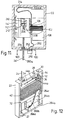
- the drive motor for rotating the grip/rod 24 is mounted directly on the housing 22.
- This drive motor 250 and a drive shaft 252 which extends from the drive motor 250 are shown in Figure 11.
- a belt 254 is used to connect a pulley 256 which is mounted on the drive shaft 252 with a pulley 258 which is also rotationally mounted on the housing 22.
- Figures 11 and 10D both show that the grip/rod 24' for this embodiment includes a plurality of splines 260, of which the splines 260a and 260b are merely exemplary.
- the splines 260 interact with the pulley 258 to allow the grip/rod 24' to slide through the pulley 258 while also requiring the grip/rod 24' to rotate with the pulley 258.
- a cable 262 is electrically connected to the central cable 214 to provide electrical power for the operation of drive motor 250.
- the operation of drive motor 250 is the same as the operation of drive motor 202. Further the operation of the optical encoder 206 remains the same regardless of the location of the drive motor 202/250.
- Figure 12 shows an alternate arrangement for the cooperation between the magnets and coil of the device 11/100.
- a plurality of magnetic segments 264 and 266 are mounted on the housing 22 with the coil 42 positioned between the segments 264 and 266.
- a series of magnetic segments 264a, 264b and 264c can be stacked with their respective North (N) and South (S) poles located as shown to establish a magnet having a strength which can be varied according to the number of magnetic segments 264 used.
- N North
- S South
- the magnetic segments 264 a, b and c are only exemplary.
- a series of magnetic segments 266, of which the magnetic segments 266a and b are exemplary can be stacked as shown to help in the creation of a magnetic field.
- Figure 13 illustrates an embodiment of the present invention which is suitable for use in a situation where rotation of the component 14 is desired, but where the required degree of precision in the rotational mode of motion is relatively low, and where only defined rotational step sizes are required.
- Figure 13 also shows an embodiment of the vacuum gripping means which can facilitate precise handling of fragile components. While the vacuum gripping means is shown in conjunction with the pneumatic rotational means, the vacuum gripping system could obviously be used with other embodiments of the invention.
- the housing 22 is shown, with the magnet 108 and the bearing rail 114 mounted inside.
- An electrical connector 251, a vacuum fitting 253, and a pneumatic fitting 255 are also shown mounted through the wall of the housing 22.
- the linear bearing 112 is slidingly mounted on the bearing rail 114, and the coil piston 106 is fixedly mounted on the linear bearing 112.
- the linear bearing 112 is precisely constrained to move along the axis of the bearing rail 114. Therefore, the linear translation of the coil piston 106 is also precisely constrained.
- the grip 24 is also mounted for precise translational movement with the coil piston 106, and the grip 24 is rotatably mounted on the coil piston 106.
- FIG 14 shows a more detailed view of the functional features of the coil piston 106.
- the grip 24 is rotatably mounted within a guide passageway 279 within the coil piston 106, while being constrained against translational movement relative to the coil piston 106.
- the guide passageway 279 and upper and lower bearings 289, 291 precisely constrain the grip 24 to rotate along a given axis.
- a cylindrical sleeve 257 is rotatably mounted on the outer surface of the grip 24 near the upper end of the grip 24.
- the cylindrical sleeve 257 fits fixedly within a cylindrical cavity 259 within the coil piston 106, near the upper end of the guide passageway 279.
- the cylindrical cavity 259 constrains the cylindrical sleeve 257 against axial or rotational movement.
- a drive coupling 261 is drivably attached to the upper end of the grip 24 and to a pneumatic rotary actuator 263 mounted on the coil piston 106.
- the rotary actuator 263 can be any such appropriately sized actuator known in the art.
- the rotary actuator 263 can be designed to rotate in increments of 90° or 180°, or some other increment, as required for the particular application, in response to applications of pressurized gas.
- Pressurized gas is supplied to the rotary actuator 263 through a pneumatic tube 265, which is fed by the pneumatic fitting 255.
- the gas supply (not shown) to the pneumatic fitting 255 can be controlled manually or by a microprocessor 70.
- a vacuum pump 72 can be connected to the vacuum fitting 253 and thence to a vacuum tube 267, which is ultimately connected to the coil piston 106.
- the vacuum tube 267 is connected to a vacuum passageway 269 within the body of the coil piston 106.
- the vacuum passageway 269 leads to the cylindrical cavity 259 where the cylindrical sleeve 257 is fixedly mounted.
- An upper sleeve O-ring 275 seated in an annular groove around the upper end of the cylindrical sleeve 257 and a lower sleeve O-ring 277 seated in an annular groove around the lower end of the cylindrical sleeve 257 seal the upper and lower ends, respectively, of the cylindrical cavity 259 against vacuum leakage.
- Upper and lower rod O-rings 281, 283 are seated in annular grooves on the outer surface of grip rod 24, against the sleeve 257, to seal against vacuum leakage between the sleeve 257 and the grip rod 24 as the grip rod 24 rotates.
- the O-rings 275, 277, 281, 283 can be made of an elastomer or another suitable material. Sealing of the grip rod 24 and the sleeve 257 in this fashion, with the O-rings 275, 277, 281, 283, allows leak-free rotation of the grip rod 24, precisely constrained by the bearings 289, 291 to provide an economical yet reliable mechanism for precisely positioning the component 14.
- a vacuum port 271 leads from the outer surface of the cylindrical sleeve 257 to the inner bore 273 of the grip 24, via an annular vacuum channel 285 in the inner surface of the sleeve 257 and via a port 287 in the grip rod 24.
- the vacuum applied to the vacuum fitting 253 and thence to the inner bore 273 of the grip 24 can be controlled manually or by a microprocessor 70 to pick up or release the component 14.
- FIG. 7 it will be seen that a microprocessor 70, of any type well known in the pertinent art, is connected to both the voltage source 46 and the sensor 48. Additionally, microprocessor 70 is connected to a vacuum pump 72 which can, in turn, be operatively connected with the grip 24. Finally, the microprocessor 70 can be connected to a compressor or other compressed gas source, which is connected to the pneumatic rotary actuator 263. Through these connections, the microprocessor 70 will interact with the voltage source 46, the sensor 48, the compressor, and the pump 72 in accordance with preprogrammed instructions.
- references here may be directed to the embodiment of the device 11 shown in Figures 2 and 4, it is to be understood that corresponding components of the apparatus 100 operate in substantially the same manner. Their operation is considered to be equivalent.
- the device 11 (apparatus 100) can be incorporated into the automated assembly machine 12 and calibrated to locate the end 74 of grip 24 at a preselected distance from the conveyor 16. This establishes a reference datum for the cycle from which movement of the grip can be measured. Actually, as will be appreciated by the skilled artisan, any other appropriate reference may be used for this purpose. Regardless what reference is used, once a reference datum from which measurements can be made has been selected, the sensor 48 can be set for this datum. In accordance with preprogrammed instructions, the microprocessor 70 then activates the voltage source 46 to send an electrical current through the coil 42.
- the current which passes through the coil 42 causes bobbin 32 (or coil piston 106 for apparatus 100) to move a distance which is proportionately determined and controlled by the amount, duration and direction of the current. It is known, for example, that with this disclosed arrangement, the grip 24 can be linearly moved through a distance of approximately two inches (2 in.) in around seventy milliseconds (70 ms) with effectively no bounce at the end of the stroke. Stated differently, movements of this nature can be made without noticeable changes in the direction of linear movement at the conclusion of the movement.
- Rotational movement of grip/rod 24 is also controlled by microprocessor 70.
- microprocessor 70 can be preprogrammed to initiate rotation of product component 18 as desired by the operator. For instance, in some operations it is necessary to align the product component 14 both linearly and angularly before it is positioned or engaged with another component of the product being manufactured. Therefore, in addition to the linear alignment of the work component 14 discussed above, device 11 must sometimes be capable of rotating the component 14 into a proper alignment. To do this, signals from optical encoder 206 which are indicative of the angular position of wheel 212 and work component 14 are sent to microprocessor 70.
- microprocessor 70 can activate servo motor 202 (or electronic drive 234) to rotate the component 14 as necessary.
- servo motor 202 or electronic drive 234.
- grip/rod 24 can be either rotated through a desired angular rotation, or the grip/rod 24 can be rotated until there is a preselected torque resistance to further rotation.
- the microprocessor 70 can control the pressurized gas supply to the rotary actuator 263 to rotate the grip 24 by 90° or 180°, or by some other angular increment, depending upon the particular actuator 263 installed.
- the microprocessor 70 can also be used to control the operation of a vacuum pump 72. This may be helpful for an embodiment of the device 11 which uses the creation of a partial vacuum in the lumen of the tubular grip 24 to hold a component 14 against the end 74 of the grip 24. It is to be recognized that other gripping arrangements may also be used, and that the vacuum gripping arrangements can be used with other embodiments.
- the partial vacuum system disclosed herein is only exemplary.
- the device 11 is initially positioned as shown in Figure 1 with the grip 24 positioned over a component 14 which is being taken into position for retrieval by the conveyor 16.
- Voltage source 46 is then activated in accordance with a preprogrammed sequence from microprocessor 70 to lower the end 74 of grip 24 into a position indicated for end 74'. In accordance with previous disclosure, this movement is accomplished by passing a predetermined current through the coil 42.
- Pump 72 is then activated to generate a partial vacuum within the lumen of grip 24 to suck and hold the component 14 against the end 74.
- Grip 24, with component 14 attached is then withdrawn into the housing 22, by the activation of coil 42, and the device 11' is positioned over conveyor 20.
- coil 42 is activated by the voltage source 46 to precisely lower component 14 to a desired stop point and into position on the component 18.
- This placement can be accomplished with great precision. For example, tolerances on the order of one one-hundredth of a millimeter (0.01 mm) have been accomplished using the device 11 of the present invention.
- sensor 48 can be used to monitor this placement and thereby provide a real-time verification of proper assembly.
- the angular rotation of the component 14 can be checked.
- the optical encoder 206 is useful for ensuring proper angular positioning of the component 14.
- microprocessor 70 is electrically connected to optical encoder 206 and, based upon signals received by microprocessor 70 from the optical encoder 206, errors in angular alignment can be corrected. This is done in a conventional manner by determining any error signals which are generated because of a difference between the actual and the desired angular orientation of the work component 14.
- microprocessor 70 can be used to control the pump 72 to relieve the vacuum created in the grip 24 to release the component 14 from the grip 24. Again, the grip 24 is withdrawn into the housing 22 and the device 11 is repositioned over the conveyor 16 for another cycle of operation.
- FIG. 8 An actual time history response for the position of rod 24 during a series of cycles is shown in Figure 8 and is designated 130.
- the response 130 is, in fact, only exemplary. Indeed, rod 24 may be moved through greater or lesser distances and the time for each cycle may be varied. Nevertheless, response 130 is considered typical for the apparatus 100 and is used here for discussion purposes. For the specific case illustrated in Figure 8, the response 130 is shown over a one second period of time and indicates that the apparatus 100 has moved rod 24 through four complete cycles during this one second interval. Further, Figure 8 shows that rod 24 was reciprocally moved through a distance of approximately one and one tenth inches (1.1 in) in each cycle.
- the position of rod 24 at any time during the cycle can be determined by encoder 122 to an accuracy within five thousandths of a millimeter (0.005 mm). Consequently, the completion of a cycle within a preprogrammed dimensional envelope can be used to indicate whether the work has been successfully completed. Additionally, with this control, and in view of the extremely small masses which are moved during the operation of apparatus 100, the forces which are generated on a workpiece as it is being handled by apparatus 100 will be very light. Tests have indicated that forces as small as five grams (5 gm) can be generated with apparatus 100 and that forces of this small magnitude can be generated with an accuracy of plus or minus one gram ( ⁇ 1 gm).
- top dead center portion 134 of curve 132 corresponds to the position 74 shown in Figure 7 and, as shown, rod 24 stays in this position during approximately the 0.00-0.04 seconds interval of the cycle.
- a positioning stroke 136 for curve 132 which immediately follows top dead center portion 134, indicates that rod 24 is quickly moved through a distance of approximately one inch during the cycle interval from 0.04-0.09 seconds. This rapid movement of the rod 24 is possible due to the relatively small mass of the components in apparatus 100 which must move with the rod 24.
- a deceleration period during the interval 0.09-0.17 seconds of the cycle is provided to steadily move the rod 24 into proper position with precision and minimal inertial forces.
- the successful completion of the work can be verified by monitoring signals from encoder 122. Specifically, by comparing signals from encoder 122, which indicate the actual position of the rod 24 at this point in the work cycle, with a reference for the programmed position for rod 24 at this point during a successful work cycle, operational deviations can be determined. If this comparison indicates only minor deviations in the position of rod 24, and these deviations are within acceptable tolerances, the work cycle can be considered successful.
- the rod 24 is withdrawn back to a top dead center position during an interval in the cycle during approximately 0.21-0.25 seconds.
- the cycle is then repeated as necessary and the same intervals are used.
- the cycle discussed here in relation to the idealized curve 132 is only exemplary.
- the parameters which establish the operational envelope for apparatus 100 and device 11 can be varied according to the desires of the operator.
Landscapes
- Engineering & Computer Science (AREA)
- Physics & Mathematics (AREA)
- Chemical & Material Sciences (AREA)
- Combustion & Propulsion (AREA)
- Electromagnetism (AREA)
- Power Engineering (AREA)
- Manipulator (AREA)
- Reciprocating, Oscillating Or Vibrating Motors (AREA)
- Automatic Assembly (AREA)
Applications Claiming Priority (2)
| Application Number | Priority Date | Filing Date | Title |
|---|---|---|---|
| US08/304,235 US5446323A (en) | 1991-09-25 | 1994-09-12 | Actuator with translational and rotational control |
| US304235 | 1994-09-12 |
Publications (3)
| Publication Number | Publication Date |
|---|---|
| EP0701316A2 true EP0701316A2 (de) | 1996-03-13 |
| EP0701316A3 EP0701316A3 (de) | 1997-04-23 |
| EP0701316B1 EP0701316B1 (de) | 2000-05-10 |
Family
ID=23175644
Family Applications (1)
| Application Number | Title | Priority Date | Filing Date |
|---|---|---|---|
| EP95300183A Expired - Lifetime EP0701316B1 (de) | 1994-09-12 | 1995-01-12 | Betätiger mit drehender und translatorischer Bewegung |
Country Status (4)
| Country | Link |
|---|---|
| US (1) | US5446323A (de) |
| EP (1) | EP0701316B1 (de) |
| JP (1) | JPH08206932A (de) |
| DE (1) | DE69516778T2 (de) |
Cited By (8)
| Publication number | Priority date | Publication date | Assignee | Title |
|---|---|---|---|---|
| EP0797287A3 (de) * | 1996-03-22 | 1997-11-19 | Systems, Machines, Automation Components Corporation | Stellantrieb für Dreh- und Linearbewegung |
| EP0891033A1 (de) * | 1997-07-08 | 1999-01-13 | Systems, Machines, Automation Components Corporation | Verformbare Welle |
| EP0868962A3 (de) * | 1997-02-26 | 1999-11-24 | Systems, Machines, Automation Components Corporation | Vorrichtung zum Bewegen eines Werkzeugs |
| EP1050384A4 (de) * | 1996-12-25 | 2000-11-08 | Matsushita Electric Industrial Co Ltd | Halte- und montagevorrichtung für bauteile, und methode zum befestigen von bauteilen |
| EP1085800A1 (de) * | 1999-09-16 | 2001-03-21 | Systems, Machines, Automation Components Corporation | Elektromagnetisch betätigbarer Greifer |
| WO2007077507A1 (en) * | 2005-12-30 | 2007-07-12 | The Gillette Company | High speed assembly actuator |
| WO2007077509A1 (en) * | 2005-12-30 | 2007-07-12 | The Gillette Company | High speed assembly actuator |
| USRE39747E1 (en) | 1997-05-02 | 2007-07-31 | Ats Automation Tooling Systems Inc. | Modular conveyor system having multiple moving elements under independent control |
Families Citing this family (34)
| Publication number | Priority date | Publication date | Assignee | Title |
|---|---|---|---|---|
| US5783915A (en) * | 1995-01-20 | 1998-07-21 | Matsushita Electric Industrial Co., Ltd. | Linear actuating apparatus |
| US5726508A (en) * | 1995-12-06 | 1998-03-10 | Systems, Machines, Automation Components Corporation | Linear voice coil retractor |
| US6118360A (en) | 1996-01-11 | 2000-09-12 | Systems, Machines, Automation Components Corporation | Linear actuator |
| US5952589A (en) * | 1996-01-11 | 1999-09-14 | Systems, Machines, Automation Components Corporation | Soft landing method for probe assembly |
| US5798582A (en) * | 1996-03-22 | 1998-08-25 | Systems, Machines, Automation Components, Corporation | Linear voice actuator with replaceable magnetic coil |
| US6091167A (en) * | 1997-06-23 | 2000-07-18 | Systems, Machines, Automation Components, Corporation | Double coil actuator |
| US5789830A (en) * | 1997-07-08 | 1998-08-04 | Systems, Machines, Automation Components Corporation | In-line rotational drive |
| US6016039A (en) * | 1997-12-05 | 2000-01-18 | Systems, Machines, Automation Components Corporation | Control processes for linear voice coil actuator |
| DE10025351A1 (de) * | 2000-05-23 | 2001-11-29 | Wittenstein Gmbh & Co Kg | Hub-/Schwenkantrieb |
| US6518682B2 (en) | 2000-12-04 | 2003-02-11 | Systems, Machines, Automation Components Corporation | System monitor for a linear/rotary actuator |
| JP3772808B2 (ja) * | 2002-08-29 | 2006-05-10 | 株式会社村田製作所 | 部品装着装置 |
| JP2006506571A (ja) * | 2002-11-19 | 2006-02-23 | エンプレサ・ブラジレイラ・ディ・コンプレッソレス・ソシエダッド・アノニマ・エンブラコ | 流体ポンプ装置のピストンの動作制御システムと方法及び流体ポンプ装置 |
| US20050234565A1 (en) * | 2004-04-01 | 2005-10-20 | Systems, Machines, Automation Components, Corporation | Programmable control system for automated actuator operation |
| US7492117B2 (en) * | 2005-07-20 | 2009-02-17 | Lawrence Livermore National Security, Llc | Electromagnetic variable degrees of freedom actuator systems and methods |
| DE112008000274T5 (de) * | 2007-01-26 | 2009-12-17 | SMAC, Inc., Carlsbad | Kombination eines pneumatischen und elektrischen Linearaktors |
| US8267388B2 (en) * | 2007-09-12 | 2012-09-18 | Xradia, Inc. | Alignment assembly |
| US9748824B2 (en) | 2012-06-25 | 2017-08-29 | Systems Machine Automation Components Corporation | Linear actuator with moving central coil and permanent side magnets |
| US9731418B2 (en) | 2008-01-25 | 2017-08-15 | Systems Machine Automation Components Corporation | Methods and apparatus for closed loop force control in a linear actuator |
| US9375848B2 (en) | 2012-06-25 | 2016-06-28 | Systems Machine Automation Components Corporation | Robotic finger |
| WO2010036204A1 (en) * | 2008-09-24 | 2010-04-01 | Chai Meng Goh | Direct drive pick and place system with reduced moving mass |
| US8827205B2 (en) * | 2009-05-08 | 2014-09-09 | Spectrum Aeronautical, Llc | Pneumatic blow-down actuator |
| EP2403118A3 (de) * | 2010-07-01 | 2014-10-29 | Kabushiki Kaisha Yaskawa Denki | Stellantrieb |
| JP5963755B2 (ja) | 2010-09-23 | 2016-08-03 | システムズ マシーンズ オートメーション コンポーネンツ コーポレイション | 低コストのマルチコイルリニアアクチュエータ |
| WO2014181451A1 (ja) * | 2013-05-10 | 2014-11-13 | 株式会社 日立製作所 | アクチュエータ |
| US10807248B2 (en) | 2014-01-31 | 2020-10-20 | Systems, Machines, Automation Components Corporation | Direct drive brushless motor for robotic finger |
| US9871435B2 (en) | 2014-01-31 | 2018-01-16 | Systems, Machines, Automation Components Corporation | Direct drive motor for robotic finger |
| US10429211B2 (en) | 2015-07-10 | 2019-10-01 | Systems, Machines, Automation Components Corporation | Apparatus and methods for linear actuator with piston assembly having an integrated controller and encoder |
| US10215802B2 (en) | 2015-09-24 | 2019-02-26 | Systems, Machines, Automation Components Corporation | Magnetically-latched actuator |
| US10517199B2 (en) * | 2015-12-17 | 2019-12-24 | Assembléon B.V. | Methods of positioning a component in a desired position on a board, pick and place machines, and sensors for such pick and place machines |
| US10865085B1 (en) * | 2016-04-08 | 2020-12-15 | Systems, Machines, Automation Components Corporation | Methods and apparatus for applying a threaded cap using a linear rotary actuator |
| US10675723B1 (en) * | 2016-04-08 | 2020-06-09 | Systems, Machines, Automation Components Corporation | Methods and apparatus for inserting a threaded fastener using a linear rotary actuator |
| US10205355B2 (en) | 2017-01-03 | 2019-02-12 | Systems, Machines, Automation Components Corporation | High-torque, low-current brushless motor |
| US20190165638A1 (en) * | 2017-11-29 | 2019-05-30 | Gp Enterprises Co., Ltd | Electric Motor Back Cover with a Sealing Structure |
| CN114285225A (zh) * | 2020-09-27 | 2022-04-05 | 国奥科技(深圳)有限公司 | 一种扁平式直线旋转电机 |
Family Cites Families (27)
| Publication number | Priority date | Publication date | Assignee | Title |
|---|---|---|---|---|
| US4421997A (en) * | 1978-09-18 | 1983-12-20 | Mcdonnell Douglas Corporation | Multiple axis actuator |
| US4231153A (en) * | 1979-02-22 | 1980-11-04 | Browne Lawrence T | Article placement system |
| US4587466A (en) * | 1982-12-09 | 1986-05-06 | Magnetic Peripherals | Two axis linear motor for optical focusing and tracking system in optical recording |
| US4498023A (en) * | 1983-10-31 | 1985-02-05 | Motorola, Inc. | Voice coil linear motor with integral capacitor |
| CA1246625A (en) * | 1984-04-06 | 1988-12-13 | Stanley R. Vancelette | Placement mechanism |
| US4575652A (en) * | 1984-09-27 | 1986-03-11 | Synektron Corporation | Permanent magnet motor having high starting torque and narrowly-defined detent zones |
| US4653794A (en) * | 1986-02-12 | 1987-03-31 | Northrop Corporation | Universal adjustable gripper with center push |
| JPS62292328A (ja) * | 1986-06-12 | 1987-12-19 | Matsushita Electric Ind Co Ltd | 部品装着方法 |
| US4739241A (en) * | 1986-10-09 | 1988-04-19 | Georgia Tech Research Corporation | Spherical motor particularly adapted for robotics |
| US4759124A (en) * | 1987-04-28 | 1988-07-26 | Universal Instruments Corp. | Method and apparatus for controlling component pickup and placement pressures |
| CA1314085C (en) * | 1988-05-25 | 1993-03-02 | Andras G. Fule | Linear interpolation for a component placement robot |
| US5251372A (en) * | 1988-08-03 | 1993-10-12 | Houghton Jon C | Method and apparatus for framing a film mounted integrated circuit |
| JP2583595B2 (ja) * | 1988-12-28 | 1997-02-19 | 日本トムソン株式会社 | 駆動装置付きボールスプライン軸受 |
| DE3904587A1 (de) * | 1989-02-16 | 1990-08-23 | Arnold & Richter Kg | Montagekopf fuer handhabungsgeraete |
| JP2773307B2 (ja) * | 1989-10-17 | 1998-07-09 | 松下電器産業株式会社 | 電子部品の実装方法 |
| DE3938088A1 (de) * | 1989-11-16 | 1991-05-23 | Bosch Gmbh Robert | Bestueckkopf fuer elektronische bauelemente |
| JPH04117157A (ja) * | 1990-05-25 | 1992-04-17 | Sony Corp | カメラレンズ駆動装置 |
| JPH07105637B2 (ja) * | 1990-05-31 | 1995-11-13 | 三洋電機株式会社 | 部品装着装置 |
| JPH0448698A (ja) * | 1990-06-14 | 1992-02-18 | Sony Corp | 電子部品取付装置 |
| US5172468A (en) * | 1990-08-22 | 1992-12-22 | Sony Corporation | Mounting apparatus for electronic parts |
| JP2531849B2 (ja) * | 1990-10-08 | 1996-09-04 | カジマメカトロエンジニアリング株式会社 | 自動ピン打ち装置 |
| US5210933A (en) * | 1990-10-30 | 1993-05-18 | Komatsu Giken Co., Ltd. | Circuit assembly robot |
| US5163728A (en) * | 1990-11-15 | 1992-11-17 | Miller Charles F | Tweezer semiconductor die attach method and apparatus |
| US5175456A (en) * | 1991-09-25 | 1992-12-29 | Systems, Machines, Automation Components Corp. | Workpiece transporter |
| US5315189A (en) * | 1991-09-25 | 1994-05-24 | Systems, Machines, Automation Corporation | Actuator with translational and rotational control |
| US5317222A (en) * | 1991-09-25 | 1994-05-31 | Systems, Machines, Automation Components Corp. | Workpiece transporter device with replaceable grip |
| US5251946A (en) * | 1992-01-21 | 1993-10-12 | Emhart Inc. | Compound tool drive |
-
1994
- 1994-09-12 US US08/304,235 patent/US5446323A/en not_active Expired - Lifetime
-
1995
- 1995-01-12 DE DE69516778T patent/DE69516778T2/de not_active Expired - Fee Related
- 1995-01-12 EP EP95300183A patent/EP0701316B1/de not_active Expired - Lifetime
- 1995-09-11 JP JP7233134A patent/JPH08206932A/ja active Pending
Cited By (9)
| Publication number | Priority date | Publication date | Assignee | Title |
|---|---|---|---|---|
| EP0797287A3 (de) * | 1996-03-22 | 1997-11-19 | Systems, Machines, Automation Components Corporation | Stellantrieb für Dreh- und Linearbewegung |
| EP1050384A4 (de) * | 1996-12-25 | 2000-11-08 | Matsushita Electric Industrial Co Ltd | Halte- und montagevorrichtung für bauteile, und methode zum befestigen von bauteilen |
| EP0868962A3 (de) * | 1997-02-26 | 1999-11-24 | Systems, Machines, Automation Components Corporation | Vorrichtung zum Bewegen eines Werkzeugs |
| USRE39747E1 (en) | 1997-05-02 | 2007-07-31 | Ats Automation Tooling Systems Inc. | Modular conveyor system having multiple moving elements under independent control |
| EP0891033A1 (de) * | 1997-07-08 | 1999-01-13 | Systems, Machines, Automation Components Corporation | Verformbare Welle |
| EP1085800A1 (de) * | 1999-09-16 | 2001-03-21 | Systems, Machines, Automation Components Corporation | Elektromagnetisch betätigbarer Greifer |
| KR100509710B1 (ko) * | 1999-09-16 | 2005-08-23 | 시스템즈, 머시인즈, 오토메이션 컴포넌츠, 코포레이션 | 선형 보이스 코일 액츄에이터용 그리퍼 |
| WO2007077507A1 (en) * | 2005-12-30 | 2007-07-12 | The Gillette Company | High speed assembly actuator |
| WO2007077509A1 (en) * | 2005-12-30 | 2007-07-12 | The Gillette Company | High speed assembly actuator |
Also Published As
| Publication number | Publication date |
|---|---|
| JPH08206932A (ja) | 1996-08-13 |
| EP0701316A3 (de) | 1997-04-23 |
| EP0701316B1 (de) | 2000-05-10 |
| DE69516778D1 (de) | 2000-06-15 |
| US5446323A (en) | 1995-08-29 |
| DE69516778T2 (de) | 2000-11-23 |
Similar Documents
| Publication | Publication Date | Title |
|---|---|---|
| EP0701316B1 (de) | Betätiger mit drehender und translatorischer Bewegung | |
| EP0534786B1 (de) | Betätigungsvorrichtung | |
| US5315189A (en) | Actuator with translational and rotational control | |
| US5317222A (en) | Workpiece transporter device with replaceable grip | |
| US12233513B2 (en) | Magnetic coupling device with at least one of a sensor arrangement and a degauss capability | |
| US7000911B2 (en) | Motor pack for automated machinery | |
| JP3727355B2 (ja) | 部品保持ヘッド、部品装着装置、及び部品保持方法 | |
| EP0797287B1 (de) | Stellantrieb für Dreh- und Linearbewegung | |
| US6719174B1 (en) | Rotary and/or linear actuator system for controlling operation of an associated tool | |
| US4987676A (en) | End effector for a robotic system | |
| CA2140326C (en) | Actuator with translational and rotational control | |
| JP3107949B2 (ja) | 交換可能なグリップを有する加工品搬送装置 | |
| US5950790A (en) | Linear stopping and positioning apparatus | |
| JP3643826B2 (ja) | 電子部品装着装置 | |
| JPH07136877A (ja) | 自動組立において組立要素を位置決めする方法および装置 | |
| JPH0197577A (ja) | ネジ締め装置 | |
| JP2823313B2 (ja) | 6軸姿勢制御装置 | |
| CN121712281A (zh) | 固晶装置及固晶方法 | |
| GB2155212A (en) | Apparatus for assembling component parts | |
| JPS63138750A (ja) | 半導体ダイスボンデイング装置のプリアライメント装置 | |
| CA2233786A1 (en) | Deformable shaft | |
| JPH06331336A (ja) | 部品の回転角度検出装置 | |
| Considine et al. | Geometric Variables I: Position, Motion, Speed, Velocity | |
| JPH0472658B2 (de) | ||
| JPH04300075A (ja) | 薄板部品の積層溶接装置 |
Legal Events
| Date | Code | Title | Description |
|---|---|---|---|
| PUAI | Public reference made under article 153(3) epc to a published international application that has entered the european phase |
Free format text: ORIGINAL CODE: 0009012 |
|
| AK | Designated contracting states |
Kind code of ref document: A2 Designated state(s): CH DE ES FR GB IT LI NL |
|
| PUAL | Search report despatched |
Free format text: ORIGINAL CODE: 0009013 |
|
| AK | Designated contracting states |
Kind code of ref document: A3 Designated state(s): CH DE ES FR GB IT LI NL |
|
| 17P | Request for examination filed |
Effective date: 19970606 |
|
| 17Q | First examination report despatched |
Effective date: 19980430 |
|
| GRAG | Despatch of communication of intention to grant |
Free format text: ORIGINAL CODE: EPIDOS AGRA |
|
| GRAG | Despatch of communication of intention to grant |
Free format text: ORIGINAL CODE: EPIDOS AGRA |
|
| GRAH | Despatch of communication of intention to grant a patent |
Free format text: ORIGINAL CODE: EPIDOS IGRA |
|
| GRAH | Despatch of communication of intention to grant a patent |
Free format text: ORIGINAL CODE: EPIDOS IGRA |
|
| GRAA | (expected) grant |
Free format text: ORIGINAL CODE: 0009210 |
|
| ITF | It: translation for a ep patent filed | ||
| AK | Designated contracting states |
Kind code of ref document: B1 Designated state(s): CH DE ES FR GB IT LI NL |
|
| PG25 | Lapsed in a contracting state [announced via postgrant information from national office to epo] |
Ref country code: LI Free format text: LAPSE BECAUSE OF FAILURE TO SUBMIT A TRANSLATION OF THE DESCRIPTION OR TO PAY THE FEE WITHIN THE PRESCRIBED TIME-LIMIT Effective date: 20000510 Ref country code: ES Free format text: THE PATENT HAS BEEN ANNULLED BY A DECISION OF A NATIONAL AUTHORITY Effective date: 20000510 Ref country code: CH Free format text: LAPSE BECAUSE OF FAILURE TO SUBMIT A TRANSLATION OF THE DESCRIPTION OR TO PAY THE FEE WITHIN THE PRESCRIBED TIME-LIMIT Effective date: 20000510 |
|
| REG | Reference to a national code |
Ref country code: CH Ref legal event code: EP |
|
| REF | Corresponds to: |
Ref document number: 69516778 Country of ref document: DE Date of ref document: 20000615 |
|
| ET | Fr: translation filed | ||
| REG | Reference to a national code |
Ref country code: CH Ref legal event code: PL |
|
| PLBE | No opposition filed within time limit |
Free format text: ORIGINAL CODE: 0009261 |
|
| STAA | Information on the status of an ep patent application or granted ep patent |
Free format text: STATUS: NO OPPOSITION FILED WITHIN TIME LIMIT |
|
| 26N | No opposition filed | ||
| REG | Reference to a national code |
Ref country code: GB Ref legal event code: IF02 |
|
| PGFP | Annual fee paid to national office [announced via postgrant information from national office to epo] |
Ref country code: FR Payment date: 20050630 Year of fee payment: 11 Ref country code: DE Payment date: 20050630 Year of fee payment: 11 |
|
| PG25 | Lapsed in a contracting state [announced via postgrant information from national office to epo] |
Ref country code: FR Free format text: LAPSE BECAUSE OF NON-PAYMENT OF DUE FEES Effective date: 20060131 |
|
| PGFP | Annual fee paid to national office [announced via postgrant information from national office to epo] |
Ref country code: IT Payment date: 20060131 Year of fee payment: 12 |
|
| PG25 | Lapsed in a contracting state [announced via postgrant information from national office to epo] |
Ref country code: DE Free format text: LAPSE BECAUSE OF NON-PAYMENT OF DUE FEES Effective date: 20060801 |
|
| REG | Reference to a national code |
Ref country code: FR Ref legal event code: ST Effective date: 20060929 |
|
| PGFP | Annual fee paid to national office [announced via postgrant information from national office to epo] |
Ref country code: GB Payment date: 20080709 Year of fee payment: 14 |
|
| GBPC | Gb: european patent ceased through non-payment of renewal fee |
Effective date: 20090112 |
|
| PG25 | Lapsed in a contracting state [announced via postgrant information from national office to epo] |
Ref country code: IT Free format text: LAPSE BECAUSE OF NON-PAYMENT OF DUE FEES Effective date: 20070112 |
|
| PG25 | Lapsed in a contracting state [announced via postgrant information from national office to epo] |
Ref country code: GB Free format text: LAPSE BECAUSE OF NON-PAYMENT OF DUE FEES Effective date: 20090112 |
|
| PGFP | Annual fee paid to national office [announced via postgrant information from national office to epo] |
Ref country code: NL Payment date: 20140110 Year of fee payment: 20 |
|
| REG | Reference to a national code |
Ref country code: NL Ref legal event code: V4 Effective date: 20150112 |