EP0884564A2 - Verschiebungssensor und Verfahren zur Produktion einer Zielmarke - Google Patents
Verschiebungssensor und Verfahren zur Produktion einer Zielmarke Download PDFInfo
- Publication number
- EP0884564A2 EP0884564A2 EP98304519A EP98304519A EP0884564A2 EP 0884564 A2 EP0884564 A2 EP 0884564A2 EP 98304519 A EP98304519 A EP 98304519A EP 98304519 A EP98304519 A EP 98304519A EP 0884564 A2 EP0884564 A2 EP 0884564A2
- Authority
- EP
- European Patent Office
- Prior art keywords
- target feature
- image
- photodetector
- ruling
- light source
- Prior art date
- Legal status (The legal status is an assumption and is not a legal conclusion. Google has not performed a legal analysis and makes no representation as to the accuracy of the status listed.)
- Granted
Links
Images


Classifications
-
- G—PHYSICS
- G01—MEASURING; TESTING
- G01D—MEASURING NOT SPECIALLY ADAPTED FOR A SPECIFIC VARIABLE; ARRANGEMENTS FOR MEASURING TWO OR MORE VARIABLES NOT COVERED IN A SINGLE OTHER SUBCLASS; TARIFF METERING APPARATUS; MEASURING OR TESTING NOT OTHERWISE PROVIDED FOR
- G01D5/00—Mechanical means for transferring the output of a sensing member; Means for converting the output of a sensing member to another variable where the form or nature of the sensing member does not constrain the means for converting; Transducers not specially adapted for a specific variable
- G01D5/26—Mechanical means for transferring the output of a sensing member; Means for converting the output of a sensing member to another variable where the form or nature of the sensing member does not constrain the means for converting; Transducers not specially adapted for a specific variable characterised by optical transfer means, i.e. using infrared, visible, or ultraviolet light
-
- G—PHYSICS
- G11—INFORMATION STORAGE
- G11B—INFORMATION STORAGE BASED ON RELATIVE MOVEMENT BETWEEN RECORD CARRIER AND TRANSDUCER
- G11B7/00—Recording or reproducing by optical means, e.g. recording using a thermal beam of optical radiation by modifying optical properties or the physical structure, reproducing using an optical beam at lower power by sensing optical properties; Record carriers therefor
- G11B7/08—Disposition or mounting of heads or light sources relatively to record carriers
- G11B7/09—Disposition or mounting of heads or light sources relatively to record carriers with provision for moving the light beam or focus plane for the purpose of maintaining alignment of the light beam relative to the record carrier during transducing operation, e.g. to compensate for surface irregularities of the latter or for track following
- G11B7/0938—Disposition or mounting of heads or light sources relatively to record carriers with provision for moving the light beam or focus plane for the purpose of maintaining alignment of the light beam relative to the record carrier during transducing operation, e.g. to compensate for surface irregularities of the latter or for track following servo format, e.g. guide tracks, pilot signals
-
- G—PHYSICS
- G01—MEASURING; TESTING
- G01D—MEASURING NOT SPECIALLY ADAPTED FOR A SPECIFIC VARIABLE; ARRANGEMENTS FOR MEASURING TWO OR MORE VARIABLES NOT COVERED IN A SINGLE OTHER SUBCLASS; TARIFF METERING APPARATUS; MEASURING OR TESTING NOT OTHERWISE PROVIDED FOR
- G01D5/00—Mechanical means for transferring the output of a sensing member; Means for converting the output of a sensing member to another variable where the form or nature of the sensing member does not constrain the means for converting; Transducers not specially adapted for a specific variable
- G01D5/26—Mechanical means for transferring the output of a sensing member; Means for converting the output of a sensing member to another variable where the form or nature of the sensing member does not constrain the means for converting; Transducers not specially adapted for a specific variable characterised by optical transfer means, i.e. using infrared, visible, or ultraviolet light
- G01D5/28—Mechanical means for transferring the output of a sensing member; Means for converting the output of a sensing member to another variable where the form or nature of the sensing member does not constrain the means for converting; Transducers not specially adapted for a specific variable characterised by optical transfer means, i.e. using infrared, visible, or ultraviolet light with deflection of beams of light, e.g. for direct optical indication
- G01D5/285—Mechanical means for transferring the output of a sensing member; Means for converting the output of a sensing member to another variable where the form or nature of the sensing member does not constrain the means for converting; Transducers not specially adapted for a specific variable characterised by optical transfer means, i.e. using infrared, visible, or ultraviolet light with deflection of beams of light, e.g. for direct optical indication using a movable mirror
-
- G—PHYSICS
- G01—MEASURING; TESTING
- G01D—MEASURING NOT SPECIALLY ADAPTED FOR A SPECIFIC VARIABLE; ARRANGEMENTS FOR MEASURING TWO OR MORE VARIABLES NOT COVERED IN A SINGLE OTHER SUBCLASS; TARIFF METERING APPARATUS; MEASURING OR TESTING NOT OTHERWISE PROVIDED FOR
- G01D5/00—Mechanical means for transferring the output of a sensing member; Means for converting the output of a sensing member to another variable where the form or nature of the sensing member does not constrain the means for converting; Transducers not specially adapted for a specific variable
- G01D5/26—Mechanical means for transferring the output of a sensing member; Means for converting the output of a sensing member to another variable where the form or nature of the sensing member does not constrain the means for converting; Transducers not specially adapted for a specific variable characterised by optical transfer means, i.e. using infrared, visible, or ultraviolet light
- G01D5/28—Mechanical means for transferring the output of a sensing member; Means for converting the output of a sensing member to another variable where the form or nature of the sensing member does not constrain the means for converting; Transducers not specially adapted for a specific variable characterised by optical transfer means, i.e. using infrared, visible, or ultraviolet light with deflection of beams of light, e.g. for direct optical indication
- G01D5/30—Mechanical means for transferring the output of a sensing member; Means for converting the output of a sensing member to another variable where the form or nature of the sensing member does not constrain the means for converting; Transducers not specially adapted for a specific variable characterised by optical transfer means, i.e. using infrared, visible, or ultraviolet light with deflection of beams of light, e.g. for direct optical indication the beams of light being detected by photocells
- G01D5/305—Mechanical means for transferring the output of a sensing member; Means for converting the output of a sensing member to another variable where the form or nature of the sensing member does not constrain the means for converting; Transducers not specially adapted for a specific variable characterised by optical transfer means, i.e. using infrared, visible, or ultraviolet light with deflection of beams of light, e.g. for direct optical indication the beams of light being detected by photocells controlling the movement of a following part
-
- G—PHYSICS
- G11—INFORMATION STORAGE
- G11B—INFORMATION STORAGE BASED ON RELATIVE MOVEMENT BETWEEN RECORD CARRIER AND TRANSDUCER
- G11B21/00—Head arrangements not specific to the method of recording or reproducing
- G11B21/02—Driving or moving of heads
- G11B21/08—Track changing or selecting during transducing operation
- G11B21/081—Access to indexed tracks or parts of continuous track
- G11B21/083—Access to indexed tracks or parts of continuous track on discs
-
- G—PHYSICS
- G11—INFORMATION STORAGE
- G11B—INFORMATION STORAGE BASED ON RELATIVE MOVEMENT BETWEEN RECORD CARRIER AND TRANSDUCER
- G11B21/00—Head arrangements not specific to the method of recording or reproducing
- G11B21/02—Driving or moving of heads
- G11B21/08—Track changing or selecting during transducing operation
- G11B21/081—Access to indexed tracks or parts of continuous track
- G11B21/086—Access to indexed tracks or parts of continuous track on tapes
-
- G—PHYSICS
- G11—INFORMATION STORAGE
- G11B—INFORMATION STORAGE BASED ON RELATIVE MOVEMENT BETWEEN RECORD CARRIER AND TRANSDUCER
- G11B5/00—Recording by magnetisation or demagnetisation of a record carrier; Reproducing by magnetic means; Record carriers therefor
- G11B5/48—Disposition or mounting of heads or head supports relative to record carriers ; arrangements of heads, e.g. for scanning the record carrier to increase the relative speed
- G11B5/4806—Disposition or mounting of heads or head supports relative to record carriers ; arrangements of heads, e.g. for scanning the record carrier to increase the relative speed specially adapted for disk drive assemblies, e.g. assembly prior to operation, hard or flexible disk drives
- G11B5/4826—Mounting, aligning or attachment of the transducer head relative to the arm assembly, e.g. slider holding members, gimbals, adhesive
-
- G—PHYSICS
- G11—INFORMATION STORAGE
- G11B—INFORMATION STORAGE BASED ON RELATIVE MOVEMENT BETWEEN RECORD CARRIER AND TRANSDUCER
- G11B5/00—Recording by magnetisation or demagnetisation of a record carrier; Reproducing by magnetic means; Record carriers therefor
- G11B5/48—Disposition or mounting of heads or head supports relative to record carriers ; arrangements of heads, e.g. for scanning the record carrier to increase the relative speed
- G11B5/54—Disposition or mounting of heads or head supports relative to record carriers ; arrangements of heads, e.g. for scanning the record carrier to increase the relative speed with provision for moving the head into or out of its operative position or across tracks
- G11B5/55—Track change, selection or acquisition by displacement of the head
- G11B5/5521—Track change, selection or acquisition by displacement of the head across disk tracks
- G11B5/5526—Control therefor; circuits, track configurations or relative disposition of servo-information transducers and servo-information tracks for control thereof
- G11B5/553—Details
- G11B5/5534—Initialisation, calibration, e.g. cylinder "set-up"
-
- G—PHYSICS
- G11—INFORMATION STORAGE
- G11B—INFORMATION STORAGE BASED ON RELATIVE MOVEMENT BETWEEN RECORD CARRIER AND TRANSDUCER
- G11B5/00—Recording by magnetisation or demagnetisation of a record carrier; Reproducing by magnetic means; Record carriers therefor
- G11B5/48—Disposition or mounting of heads or head supports relative to record carriers ; arrangements of heads, e.g. for scanning the record carrier to increase the relative speed
- G11B5/58—Disposition or mounting of heads or head supports relative to record carriers ; arrangements of heads, e.g. for scanning the record carrier to increase the relative speed with provision for moving the head for the purpose of maintaining alignment of the head relative to the record carrier during transducing operation, e.g. to compensate for surface irregularities of the latter or for track following
- G11B5/596—Disposition or mounting of heads or head supports relative to record carriers ; arrangements of heads, e.g. for scanning the record carrier to increase the relative speed with provision for moving the head for the purpose of maintaining alignment of the head relative to the record carrier during transducing operation, e.g. to compensate for surface irregularities of the latter or for track following for track following on disks
- G11B5/59677—Disposition or mounting of heads or head supports relative to record carriers ; arrangements of heads, e.g. for scanning the record carrier to increase the relative speed with provision for moving the head for the purpose of maintaining alignment of the head relative to the record carrier during transducing operation, e.g. to compensate for surface irregularities of the latter or for track following for track following on disks with optical servo tracking
-
- G—PHYSICS
- G11—INFORMATION STORAGE
- G11B—INFORMATION STORAGE BASED ON RELATIVE MOVEMENT BETWEEN RECORD CARRIER AND TRANSDUCER
- G11B7/00—Recording or reproducing by optical means, e.g. recording using a thermal beam of optical radiation by modifying optical properties or the physical structure, reproducing using an optical beam at lower power by sensing optical properties; Record carriers therefor
- G11B7/007—Arrangement of the information on the record carrier, e.g. form of tracks, actual track shape, e.g. wobbled, or cross-section, e.g. v-shaped; Sequential information structures, e.g. sectoring or header formats within a track
-
- G—PHYSICS
- G11—INFORMATION STORAGE
- G11B—INFORMATION STORAGE BASED ON RELATIVE MOVEMENT BETWEEN RECORD CARRIER AND TRANSDUCER
- G11B7/00—Recording or reproducing by optical means, e.g. recording using a thermal beam of optical radiation by modifying optical properties or the physical structure, reproducing using an optical beam at lower power by sensing optical properties; Record carriers therefor
- G11B7/12—Heads, e.g. forming of the optical beam spot or modulation of the optical beam
- G11B7/13—Optical detectors therefor
-
- G—PHYSICS
- G11—INFORMATION STORAGE
- G11B—INFORMATION STORAGE BASED ON RELATIVE MOVEMENT BETWEEN RECORD CARRIER AND TRANSDUCER
- G11B7/00—Recording or reproducing by optical means, e.g. recording using a thermal beam of optical radiation by modifying optical properties or the physical structure, reproducing using an optical beam at lower power by sensing optical properties; Record carriers therefor
- G11B7/24—Record carriers characterised by shape, structure or physical properties, or by the selection of the material
- G11B7/24097—Structures for detection, control, recording operation or replay operation; Special shapes or structures for centering or eccentricity prevention; Arrangements for testing, inspecting or evaluating; Containers, cartridges or cassettes
-
- G—PHYSICS
- G11—INFORMATION STORAGE
- G11B—INFORMATION STORAGE BASED ON RELATIVE MOVEMENT BETWEEN RECORD CARRIER AND TRANSDUCER
- G11B7/00—Recording or reproducing by optical means, e.g. recording using a thermal beam of optical radiation by modifying optical properties or the physical structure, reproducing using an optical beam at lower power by sensing optical properties; Record carriers therefor
- G11B7/007—Arrangement of the information on the record carrier, e.g. form of tracks, actual track shape, e.g. wobbled, or cross-section, e.g. v-shaped; Sequential information structures, e.g. sectoring or header formats within a track
- G11B2007/00709—Dimensions of grooves or tracks, e.g. groove depth, track pitch
-
- G—PHYSICS
- G11—INFORMATION STORAGE
- G11B—INFORMATION STORAGE BASED ON RELATIVE MOVEMENT BETWEEN RECORD CARRIER AND TRANSDUCER
- G11B7/00—Recording or reproducing by optical means, e.g. recording using a thermal beam of optical radiation by modifying optical properties or the physical structure, reproducing using an optical beam at lower power by sensing optical properties; Record carriers therefor
- G11B7/007—Arrangement of the information on the record carrier, e.g. form of tracks, actual track shape, e.g. wobbled, or cross-section, e.g. v-shaped; Sequential information structures, e.g. sectoring or header formats within a track
- G11B2007/00754—Track shape, e.g. address or synchronisation information in wobbled track or sidewall
Definitions
- the target feature groove is semi-cylindrical in shape.
- Fig. 1 is a general block diagram of one embodiment of a displacement sensor employing a target feature formed according to the invention.
- the sensor includes a stationary light source 10, a movable object 14, a stationary imaging lens 26 and a stationary photodetector 20.
- a target feature 16 is attached to, or integral with, movable object 14.
- Object 14 is movable in the direction shown by arrow X and the displacement sensor monitors the position of object 14 by measuring displacements of object 14 from a reference position.
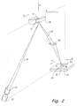
- Fig. 2 is a more detailed diagram showing a particular embodiment of the displacement sensor of the present invention. Like elements in Fig. 2 are referred to by identical reference characters to those in Fig. 1. As shown, the sensor includes laser diode light source 22, object 14, to which target feature 16 is attached, or with which target feature 16 is formed integral, and bi-cell photodetector 28. Also included are a gradient index (GRIN) incident laser diode beam collimating lens 24 and reflected beam focussing lens 26.
- GRIN gradient index
- the light source 10 can be any type of light source that produces an incident light beam having sufficient intensity to be detected by the photodetector to meet the sensitivity requirements of a particular application.
- the light source can, for examples, include a laser diode, a light emitting diode (LED), an LED, a tungsten light source, or an optical fiber light source. If an optical fiber light source is employed, then a pair of optical fibers, or a bifurcated fiber, would be employed to direct the reflected laser beams to the photodetector.
- the power of the light source preferably falls within the range of .1 milliwatt - 20 milliwatt.
- the strength of the incident laser beam preferably is approximately equal to 1 mwatt/100 ⁇ .
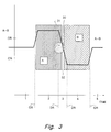
- Two positions of target feature 16 are shown in Fig. 9: A first position (in which the target feature is shown in solid lines), and a second position (in which the target feature is shown in phantom).
- the second position shows the target feature displaced from its first position in the lateral direction X, which displacement is to be measured by the system of the invention.
- a portion of the reflected beams 18 is received by imaging lens 26 and focused onto a surface of photodetector 20.
- a second image 100A' is formed on surface of photodetector 20.
- a second image 100B' is formed on surface of photodetector 20.
- second point-like image moves from position 100A' to position 100B' (which corresponds to movement in the X' direction of image 30 on surface 31 of photodetector 20 in Fig. 2).
- second image 100A' (and 100B') corresponds to second image 30 in Fig. 2.
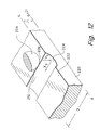
- the target feature can be formed integral with the object (i.e., E block to which head arms are attached if used in disk drive servo system application) by a process according to the invention.
- the process includes ruling the target feature into a surface of the object with a tool having a ruling portion.
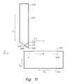
- Fig. 10 shows one embodiment of a ruling tool that can be used for ruling a target feature according to the invention.
- the ruling tool 200 includes a handle portion 202 and a ruling portion 204.
- Handle portion generally is longitudinal and may have any cross sectional shape including rectangular (as shown), square, octagonal, round or other.
- the ruling portion 204 is attached to a distal end of handle 202 by any suitable means such as being machine-fitted, adhesively attached, or other.
- Ruling portion 204 may be retained tightly within distal end of handle 202 such that a tight tolerance exists along interface 210 between ruling portion 204 and handle 202.
Landscapes
- Physics & Mathematics (AREA)
- General Physics & Mathematics (AREA)
- Optics & Photonics (AREA)
- Length Measuring Devices By Optical Means (AREA)
- Moving Of The Head To Find And Align With The Track (AREA)
- Measurement Of Optical Distance (AREA)
Applications Claiming Priority (2)
| Application Number | Priority Date | Filing Date | Title |
|---|---|---|---|
| US08/872,607 US5886787A (en) | 1995-12-15 | 1997-06-10 | Displacement sensor and method for producing target feature thereof |
| US872607 | 1997-06-10 |
Publications (3)
| Publication Number | Publication Date |
|---|---|
| EP0884564A2 true EP0884564A2 (de) | 1998-12-16 |
| EP0884564A3 EP0884564A3 (de) | 2000-08-23 |
| EP0884564B1 EP0884564B1 (de) | 2004-04-28 |
Family
ID=25359943
Family Applications (1)
| Application Number | Title | Priority Date | Filing Date |
|---|---|---|---|
| EP98304519A Expired - Lifetime EP0884564B1 (de) | 1997-06-10 | 1998-06-08 | Verschiebungssensor und Verfahren zur Produktion einer Zielmarke |
Country Status (6)
| Country | Link |
|---|---|
| US (1) | US5886787A (de) |
| EP (1) | EP0884564B1 (de) |
| JP (1) | JPH1151610A (de) |
| KR (1) | KR19990006856A (de) |
| SG (1) | SG72783A1 (de) |
| TW (1) | TW409178B (de) |
Cited By (2)
| Publication number | Priority date | Publication date | Assignee | Title |
|---|---|---|---|---|
| EP1804034A1 (de) * | 2005-12-28 | 2007-07-04 | Advanced Mask Technology Center GmbH & Co. KG | System zur Positionsüberwachung einer Düse |
| IT202200004877A1 (it) * | 2022-03-14 | 2023-09-14 | El En Spa | Dispositivo per il movimento di un gruppo ottico, testa di processo laser comprendente il dispositivo e apparecchiatura comprendente la testa di processo laser |
Families Citing this family (6)
| Publication number | Priority date | Publication date | Assignee | Title |
|---|---|---|---|---|
| US6348943B1 (en) * | 1998-10-30 | 2002-02-19 | Industrial Technology Research Institute | Digital non-contact blade position detection apparatus |
| US20070253102A1 (en) * | 2006-05-01 | 2007-11-01 | Maxtor Corporation | Disc Clamp Having Laser Reflectivity |
| US8606426B2 (en) * | 2009-10-23 | 2013-12-10 | Academia Sinica | Alignment and anti-drift mechanism |
| JP5460352B2 (ja) * | 2010-01-22 | 2014-04-02 | キヤノン株式会社 | 変位測定装置および速度測定装置 |
| US20110317153A1 (en) * | 2010-06-24 | 2011-12-29 | Apple Inc. | Laser peak energy point calibration method and apparatus |
| ITUA20162698A1 (it) * | 2016-04-19 | 2017-10-19 | Mer Mec S P A | Sistema ottico per la misura della forza di contatto tra il pantografo e la catenaria |
Family Cites Families (49)
| Publication number | Priority date | Publication date | Assignee | Title |
|---|---|---|---|---|
| US2948890A (en) * | 1956-04-26 | 1960-08-09 | Dell Brothers O | Position meter |
| US4012843A (en) * | 1973-04-25 | 1977-03-22 | Hitachi, Ltd. | Concave diffraction grating and a manufacturing method thereof |
| JPS5845111B2 (ja) * | 1977-03-02 | 1983-10-07 | 株式会社日立製作所 | 磁気ヘッド位置ぎめ装置 |
| US4122551A (en) * | 1977-04-08 | 1978-10-24 | Xerox Corporation | Optical data storage and retrieval system |
| JPS5938668B2 (ja) * | 1978-10-02 | 1984-09-18 | 日本電信電話株式会社 | サ−ボ信号書込装置 |
| JPS58135906A (ja) * | 1982-02-08 | 1983-08-12 | Toshiba Corp | 磁気デイスク装置 |
| JPS58139370A (ja) * | 1982-02-12 | 1983-08-18 | Sansui Electric Co | 円盤状記録媒体の読取装置 |
| JPS58216651A (ja) | 1982-06-08 | 1983-12-16 | Japan Tobacco Inc | スナツク食品の製造法 |
| JPS60209981A (ja) * | 1984-03-31 | 1985-10-22 | Toshiba Corp | 高密度螺旋描画装置 |
| US4823170A (en) * | 1985-02-22 | 1989-04-18 | Position Orientation Systems, Ltd. | Line of sight measuring system |
| JPH0632177B2 (ja) * | 1986-05-01 | 1994-04-27 | 日立電子エンジニアリング株式会社 | サ−ボトラツクライタにおけるサ−ボヘツドのオフセツト方法 |
| JPS62298061A (ja) * | 1986-06-16 | 1987-12-25 | Seiko Epson Corp | 磁気デイスク装置 |
| DE3643723A1 (de) * | 1986-12-20 | 1988-07-07 | Leitz Ernst Gmbh | Verfahren und anordnung zur optischen messung des rollwinkels eines bewegten maschinenteils |
| JPS63184972A (ja) * | 1987-01-27 | 1988-07-30 | Hitachi Electronics Eng Co Ltd | 磁気ヘツドの位置決め制御方式 |
| US4786815A (en) * | 1987-02-12 | 1988-11-22 | K. J. Law Engineers, Inc. | Non-contact sensor with particular utility for measurement of road profile |
| JPS63271777A (ja) * | 1987-04-28 | 1988-11-09 | Hitachi Ltd | サ−ボライト装置 |
| LU87003A1 (fr) * | 1987-09-29 | 1989-04-06 | Europ Communities | Systeme de poursuite d'une cible |
| JPH01137463A (ja) * | 1987-11-24 | 1989-05-30 | Mitsubishi Electric Corp | サーボトラツクライタ |
| JPH01184676A (ja) * | 1988-01-12 | 1989-07-24 | Mitsubishi Electric Corp | 磁気ディスク用サーボトラック書込装置 |
| JPH0828083B2 (ja) * | 1988-05-24 | 1996-03-21 | 株式会社東芝 | サーボトラックライタの記録位置補正方法 |
| JPH02134778A (ja) * | 1988-11-16 | 1990-05-23 | Nippon Telegr & Teleph Corp <Ntt> | 位置決め制御装置 |
| JP2553716B2 (ja) * | 1989-11-02 | 1996-11-13 | 富士通株式会社 | 磁気ディスク装置 |
| JPH02276073A (ja) * | 1990-03-08 | 1990-11-09 | Hitachi Electron Eng Co Ltd | 磁気ディスクサーボトラック書込み検査方式 |
| JPH03272066A (ja) * | 1990-03-20 | 1991-12-03 | Fujitsu Ltd | サーボトラック書込み方法及びその装置 |
| JP2564963B2 (ja) * | 1990-03-29 | 1996-12-18 | 三菱電機株式会社 | ターゲット及びこれを用いた三次元位置姿勢計測システム |
| JP2579232B2 (ja) * | 1990-04-03 | 1997-02-05 | 日立電子エンジニアリング株式会社 | サーボ信号書込装置 |
| US5079432A (en) * | 1990-06-25 | 1992-01-07 | Ampex Corporation | Method and apparatus for measuring the displacement of an automatic scan tracking head |
| FR2666145B1 (fr) * | 1990-08-27 | 1994-05-20 | Jaeger | Perfectionnements aux capteurs optiques. |
| JP2617237B2 (ja) * | 1990-08-28 | 1997-06-04 | シャープ株式会社 | 光スポット位置検出装置 |
| US5144833A (en) * | 1990-09-27 | 1992-09-08 | International Business Machines Corporation | Atomic force microscopy |
| US5268801A (en) * | 1990-10-12 | 1993-12-07 | Servo Track Writer Corporation | Method and apparatus for effecting data transfer with high precision reference data on a rotatable storage media |
| US5319509A (en) * | 1990-10-12 | 1994-06-07 | Servo Track Writer Corporation | Method and apparatus for controlling and analyzing a data storage system |
| GB9022969D0 (en) * | 1990-10-23 | 1990-12-05 | Rosemount Ltd | Displacement measurement apparatus |
| US5325349A (en) * | 1991-05-29 | 1994-06-28 | Sony Magnescale Inc. | Hard disc drive and a servo signal writing apparatus |
| JP3023206B2 (ja) * | 1991-06-06 | 2000-03-21 | 株式会社東芝 | サーボライタのヘッド位置決め装置 |
| US5235416A (en) * | 1991-07-30 | 1993-08-10 | The Government Of The United States Of America As Represented By The Secretary Of The Department Of Health & Human Services | System and method for preforming simultaneous bilateral measurements on a subject in motion |
| JP2710879B2 (ja) * | 1991-08-07 | 1998-02-10 | 尚武 毛利 | レーザ測定方法及び装置 |
| JPH05198110A (ja) * | 1991-08-30 | 1993-08-06 | Canon Inc | ヘッド位置決め装置 |
| EP0530698B1 (de) * | 1991-08-30 | 1997-08-13 | Canon Kabushiki Kaisha | Kopfpositionierungsgerät |
| US5165045A (en) * | 1991-10-10 | 1992-11-17 | Eselun Steven A | Method and apparatus for measuring displacement having parallel grating lines perpendicular to a displacement direction for diffracting a light beam |
| JPH05256641A (ja) * | 1992-03-11 | 1993-10-05 | Olympus Optical Co Ltd | カンチレバー変位検出装置 |
| US5311378A (en) * | 1992-05-05 | 1994-05-10 | Insite Peripherals, Inc. | Dual very-high density magnetic head assembly with optical servo positioning for very high density floppy disk recording and high density format compatability |
| JPH06103714A (ja) * | 1992-09-22 | 1994-04-15 | Hitachi Electron Eng Co Ltd | ハードディスクドライブ装置の非接触式外部キャリッジ機構 |
| US5367373A (en) * | 1992-11-19 | 1994-11-22 | Board Of Regents, The University Of Texas System | Noncontact position measurement systems using optical sensors |
| US5315372A (en) * | 1993-01-04 | 1994-05-24 | Excel Precision, Inc. | Non-contact servo track writing apparatus having read/head arm and reference arm |
| JPH06212972A (ja) * | 1993-01-14 | 1994-08-02 | Tokyo Gas Co Ltd | エンジンの冷却方法及び冷却装置 |
| US5424556A (en) * | 1993-11-30 | 1995-06-13 | Honeywell Inc. | Gradient reflector location sensing system |
| US5771130A (en) * | 1996-04-15 | 1998-06-23 | Phase Metrics | Method and apparatus for non-contact servo writing |
| JP3893678B2 (ja) | 1997-07-22 | 2007-03-14 | 株式会社トヨトミ | 可変抵抗入力機能付プレート |
-
1997
- 1997-06-10 US US08/872,607 patent/US5886787A/en not_active Expired - Fee Related
-
1998
- 1998-01-19 SG SG1998000134A patent/SG72783A1/en unknown
- 1998-02-12 TW TW087101938A patent/TW409178B/zh not_active IP Right Cessation
- 1998-06-08 EP EP98304519A patent/EP0884564B1/de not_active Expired - Lifetime
- 1998-06-09 JP JP10160511A patent/JPH1151610A/ja active Pending
- 1998-06-10 KR KR1019980021594A patent/KR19990006856A/ko not_active Ceased
Cited By (3)
| Publication number | Priority date | Publication date | Assignee | Title |
|---|---|---|---|---|
| EP1804034A1 (de) * | 2005-12-28 | 2007-07-04 | Advanced Mask Technology Center GmbH & Co. KG | System zur Positionsüberwachung einer Düse |
| IT202200004877A1 (it) * | 2022-03-14 | 2023-09-14 | El En Spa | Dispositivo per il movimento di un gruppo ottico, testa di processo laser comprendente il dispositivo e apparecchiatura comprendente la testa di processo laser |
| WO2023175474A1 (en) * | 2022-03-14 | 2023-09-21 | El.En. S.P.A. | Device for movement of an optical unit, laser process head comprising the device and equipment comprising the laser process head |
Also Published As
| Publication number | Publication date |
|---|---|
| TW409178B (en) | 2000-10-21 |
| KR19990006856A (ko) | 1999-01-25 |
| JPH1151610A (ja) | 1999-02-26 |
| EP0884564B1 (de) | 2004-04-28 |
| EP0884564A3 (de) | 2000-08-23 |
| US5886787A (en) | 1999-03-23 |
| SG72783A1 (en) | 2000-05-23 |
Similar Documents
| Publication | Publication Date | Title |
|---|---|---|
| US5982494A (en) | Non-contact position sensor | |
| US6633051B1 (en) | Surface sensing device with optical sensor | |
| US6459492B1 (en) | Non-contact position sensor | |
| US5118956A (en) | Touch probe including a waveguide | |
| JP3932502B2 (ja) | 触針式形状測定センサとこれを用いたnc加工装置および形状測定方法 | |
| US4897536A (en) | Optical axis displacement sensor with cylindrical lens means | |
| US6137580A (en) | Autofocus system | |
| JPS62232503A (ja) | 微小な長さを測定する装置 | |
| JPH0743251B2 (ja) | 光学式変位計 | |
| US5886787A (en) | Displacement sensor and method for producing target feature thereof | |
| EP0234562A2 (de) | Verschiebungsmessfühler | |
| US6253010B1 (en) | System and method for efficient coupling between optical elements | |
| US7247827B1 (en) | System for measurement of the height, angle and their variations of the surface of an object | |
| US6759669B2 (en) | Multi-point distance measurement device | |
| KR100498192B1 (ko) | 비-접촉 위치 센서 | |
| JP3413503B2 (ja) | 変位検出装置 | |
| JPH04366711A (ja) | 変位検出装置 | |
| CN1205428A (zh) | 位移传感器及其形成目标特征部分的方法 | |
| JPH11304463A (ja) | 形状測定装置および形状測定方法 | |
| JP2609606B2 (ja) | 光ピツクアツプの対物レンズ位置検出装置 | |
| JPH03252513A (ja) | パラボラアンテナ面形状測定装置 | |
| JPH0362328A (ja) | 光学装置の焦点位置検出装置 | |
| JPH01239408A (ja) | 微小変位および微小傾角の測定方法 | |
| JPS61129510A (ja) | 多次元センサ | |
| JPH0288913A (ja) | 角度測定器 |
Legal Events
| Date | Code | Title | Description |
|---|---|---|---|
| PUAI | Public reference made under article 153(3) epc to a published international application that has entered the european phase |
Free format text: ORIGINAL CODE: 0009012 |
|
| AK | Designated contracting states |
Kind code of ref document: A2 Designated state(s): GB IE |
|
| AX | Request for extension of the european patent |
Free format text: AL;LT;LV;MK;RO;SI |
|
| PUAL | Search report despatched |
Free format text: ORIGINAL CODE: 0009013 |
|
| AK | Designated contracting states |
Kind code of ref document: A3 Designated state(s): AT BE CH CY DE DK ES FI FR GB GR IE IT LI LU MC NL PT SE |
|
| AX | Request for extension of the european patent |
Free format text: AL;LT;LV;MK;RO;SI |
|
| RIC1 | Information provided on ipc code assigned before grant |
Free format text: 7G 01D 5/26 A, 7G 11B 5/55 B, 7G 11B 5/596 B, 7G 01D 5/28 B, 7G 01D 5/30 B |
|
| 17P | Request for examination filed |
Effective date: 20010125 |
|
| RAP1 | Party data changed (applicant data changed or rights of an application transferred) |
Owner name: AGILENT TECHNOLOGIES, INC. |
|
| AKX | Designation fees paid |
Free format text: GB IE |
|
| REG | Reference to a national code |
Ref country code: DE Ref legal event code: 8566 |
|
| RAP1 | Party data changed (applicant data changed or rights of an application transferred) |
Owner name: AGILENT TECHNOLOGIES INC. |
|
| RAP1 | Party data changed (applicant data changed or rights of an application transferred) |
Owner name: AGILENT TECHNOLOGIES INC. A DELAWARE CORPORATION |
|
| RAP1 | Party data changed (applicant data changed or rights of an application transferred) |
Owner name: AGILENT TECHNOLOGIES, INC. (A DELAWARE CORPORATION |
|
| 17Q | First examination report despatched |
Effective date: 20030317 |
|
| GRAP | Despatch of communication of intention to grant a patent |
Free format text: ORIGINAL CODE: EPIDOSNIGR1 |
|
| GRAS | Grant fee paid |
Free format text: ORIGINAL CODE: EPIDOSNIGR3 |
|
| GRAA | (expected) grant |
Free format text: ORIGINAL CODE: 0009210 |
|
| AK | Designated contracting states |
Kind code of ref document: B1 Designated state(s): GB IE |
|
| REG | Reference to a national code |
Ref country code: GB Ref legal event code: FG4D |
|
| REG | Reference to a national code |
Ref country code: IE Ref legal event code: FG4D |
|
| PLBE | No opposition filed within time limit |
Free format text: ORIGINAL CODE: 0009261 |
|
| STAA | Information on the status of an ep patent application or granted ep patent |
Free format text: STATUS: NO OPPOSITION FILED WITHIN TIME LIMIT |
|
| 26N | No opposition filed |
Effective date: 20050131 |
|
| PGFP | Annual fee paid to national office [announced via postgrant information from national office to epo] |
Ref country code: GB Payment date: 20060626 Year of fee payment: 9 |
|
| PGFP | Annual fee paid to national office [announced via postgrant information from national office to epo] |
Ref country code: IE Payment date: 20060627 Year of fee payment: 9 |
|
| GBPC | Gb: european patent ceased through non-payment of renewal fee |
Effective date: 20070608 |
|
| REG | Reference to a national code |
Ref country code: IE Ref legal event code: MM4A |
|
| PG25 | Lapsed in a contracting state [announced via postgrant information from national office to epo] |
Ref country code: IE Free format text: LAPSE BECAUSE OF NON-PAYMENT OF DUE FEES Effective date: 20070608 Ref country code: GB Free format text: LAPSE BECAUSE OF NON-PAYMENT OF DUE FEES Effective date: 20070608 |