EP0950919A2 - Vorrichtung und Verfahren zum Lesen magnetisch gespeicherter Daten von photographischem Film beim Spulen - Google Patents
Vorrichtung und Verfahren zum Lesen magnetisch gespeicherter Daten von photographischem Film beim Spulen Download PDFInfo
- Publication number
- EP0950919A2 EP0950919A2 EP99106500A EP99106500A EP0950919A2 EP 0950919 A2 EP0950919 A2 EP 0950919A2 EP 99106500 A EP99106500 A EP 99106500A EP 99106500 A EP99106500 A EP 99106500A EP 0950919 A2 EP0950919 A2 EP 0950919A2
- Authority
- EP
- European Patent Office
- Prior art keywords
- magnetic data
- film
- frame
- read
- reading
- Prior art date
- Legal status (The legal status is an assumption and is not a legal conclusion. Google has not performed a legal analysis and makes no representation as to the accuracy of the status listed.)
- Granted
Links
Images


Classifications
-
- G—PHYSICS
- G11—INFORMATION STORAGE
- G11B—INFORMATION STORAGE BASED ON RELATIVE MOVEMENT BETWEEN RECORD CARRIER AND TRANSDUCER
- G11B15/00—Driving, starting or stopping record carriers of filamentary or web form; Driving both such record carriers and heads; Guiding such record carriers or containers therefor; Control thereof; Control of operating function
- G11B15/02—Control of operating function, e.g. switching from recording to reproducing
- G11B15/05—Control of operating function, e.g. switching from recording to reproducing by sensing features present on or derived from record carrier or container
- G11B15/087—Control of operating function, e.g. switching from recording to reproducing by sensing features present on or derived from record carrier or container by sensing recorded signals
-
- G—PHYSICS
- G03—PHOTOGRAPHY; CINEMATOGRAPHY; ANALOGOUS TECHNIQUES USING WAVES OTHER THAN OPTICAL WAVES; ELECTROGRAPHY; HOLOGRAPHY
- G03B—APPARATUS OR ARRANGEMENTS FOR TAKING PHOTOGRAPHS OR FOR PROJECTING OR VIEWING THEM; APPARATUS OR ARRANGEMENTS EMPLOYING ANALOGOUS TECHNIQUES USING WAVES OTHER THAN OPTICAL WAVES; ACCESSORIES THEREFOR
- G03B27/00—Photographic printing apparatus
- G03B27/32—Projection printing apparatus, e.g. enlarger, copying camera
- G03B27/52—Details
- G03B27/62—Holders for the original
- G03B27/6271—Holders for the original in enlargers
- G03B27/6285—Handling strips
-
- G—PHYSICS
- G11—INFORMATION STORAGE
- G11B—INFORMATION STORAGE BASED ON RELATIVE MOVEMENT BETWEEN RECORD CARRIER AND TRANSDUCER
- G11B15/00—Driving, starting or stopping record carriers of filamentary or web form; Driving both such record carriers and heads; Guiding such record carriers or containers therefor; Control thereof; Control of operating function
- G11B15/02—Control of operating function, e.g. switching from recording to reproducing
- G11B15/026—Control of operating function, e.g. switching from recording to reproducing by using processor, e.g. microcomputer
-
- G—PHYSICS
- G11—INFORMATION STORAGE
- G11B—INFORMATION STORAGE BASED ON RELATIVE MOVEMENT BETWEEN RECORD CARRIER AND TRANSDUCER
- G11B15/00—Driving, starting or stopping record carriers of filamentary or web form; Driving both such record carriers and heads; Guiding such record carriers or containers therefor; Control thereof; Control of operating function
- G11B15/18—Driving; Starting; Stopping; Arrangements for control or regulation thereof
- G11B15/20—Moving record carrier backwards or forwards by finite amounts, i.e. backspacing, forward spacing
-
- G—PHYSICS
- G03—PHOTOGRAPHY; CINEMATOGRAPHY; ANALOGOUS TECHNIQUES USING WAVES OTHER THAN OPTICAL WAVES; ELECTROGRAPHY; HOLOGRAPHY
- G03B—APPARATUS OR ARRANGEMENTS FOR TAKING PHOTOGRAPHS OR FOR PROJECTING OR VIEWING THEM; APPARATUS OR ARRANGEMENTS EMPLOYING ANALOGOUS TECHNIQUES USING WAVES OTHER THAN OPTICAL WAVES; ACCESSORIES THEREFOR
- G03B2206/00—Systems for exchange of information between different pieces of apparatus, e.g. for exchanging trimming information, for photo finishing
- G03B2206/004—Systems for exchange of information between different pieces of apparatus, e.g. for exchanging trimming information, for photo finishing using markings on the photographic material, e.g. to indicate pseudo-panoramic exposure
- G03B2206/006—Systems for exchange of information between different pieces of apparatus, e.g. for exchanging trimming information, for photo finishing using markings on the photographic material, e.g. to indicate pseudo-panoramic exposure of the bar-code type
Definitions
- the present invention relates to apparatus and method for feeding a film and, particularly to film feeding apparatus and method for winding or rewinding a film, e.g. compatible with the APS (advanced photo system) in a cartridge in order to read magnetic data recorded on the film.
- APS advanced photo system
- Magnetic data are written on an APS film by a photo processing apparatus or camera, and the written magnetic data are read by a magnetic head only during the scanning of a film image information.
- the magnetic data may fail to be read by being influenced by an amount of magnetic data to be recorded by a camera used for photographing, treatment liquids used to develop a film, the state of a magnetic reading device when the magnetic data are read, and other factors.
- an operator is notified of an error in reading the magnetic data via a monitor. If the operator gives a command to reread the image data in response to the notification, scanning is performed again to reread the magnetic data.
- the magnetic data are reread, they are read on the same condition (at the same speed) at every scanning. Accordingly, if the film has a poor recorded state and/or the recording density of the magnetic data is very high or very low, the magnetic data may not be read even despite repeated attempts to reread or an error may be detected. This leads not only to a poor operability, but also to a reduction in the reliability of the apparatus.
- a main object of the present invention is to provide film feeding apparatus and method which can have or secure improved operability and reliability.
- the invention is directed to a film feeding apparatus for feeding a film so that magnetic data recorded on the film can be read, comprising:
- the magnetic data are read again after changing the reading condition if it was judged, based on the information on the magnetic data of the respective frames which were read while the film was being wound, that there was a frame whose magnetic data had not been read yet or was not properly read.
- the reading condition By changing the reading condition, there is a higher possibility of reading the magnetic data which was not read while the film was wound and, as a result, a reading rate of the magnetic data can be improved.
- the second reading means comprises means for reading the magnetic data while the film is being rewound.
- the magnetic data are read again while the film is rewound to its leading end in the case that the magnetic data failed to be read by the magnetic data reading during the winding of the film.
- the reading condition is made different from the one when the film is wound (the film feeding direction is reversed) and a chance to read the magnetic data is increased. Therefore, the reading rate of the magnetic data can be improved.
- the first reading means reads the magnetic data by intermittently feeding the film frame by frame
- the second reading means reads the magnetic data by continuously feeding the film.
- the magnetic data are read by intermittently feeding the film frame by frame while the film is wound, while being read by continuously feeding the film to its leading end while the film is rewound.
- the reading condition of the magnetic data when the film is rewound can be made further different from the one when the film is wound.
- a rereading means for changing the reading condition again if there is a frame whose magnetic data has not been read yet even after the rewinding of the film, rereading the magnetic data, and storing the read magnetic data in the storage means.
- the rereading means comprises means for notifying an operator that there is a frame whose magnetic data has not been read yet even after the rewinding of the film, and means for changing a feeding speed of the film upon receipt of a command from the operator to reread the magnetic data again and rereading the magnetic data.
- the feeding speed of the film is changed upon receipt of a corresponding command from the operator and the magnetic data are reread again.
- the magnetic data can be so read as to conform to its recording density, if necessary, and the reading rate of the magnetic data can be further improved.
- the storage means stores flags indicative of the magnetic data of each frame and the presence or absence of the magnetic data for each frame
- the first judging means comprises a second judging means for judging, based on the flags stored in the storage means, whether or not there is any frame whose magnetic data has not been read yet.
- the second judging means refers to the flags and judges that a reading error occurred in reading the magnetic data for the frame, for which no magnetic data has been read, if the presence/absence of the magnetic data between adjacent or successive frames has changed twice or more.
- the judgment as to whether or not there is any frame whose magnetic data has not been read yet can be made in consideration of the case where no magnetic data is recorded on the film, the case where the film is exposed from its intermediate frame, and the case where the film is exposed to its intermediate frame.
- the second reading means may change the feeding speed of the film after the film is rewound and may reread the magnetic data.
- the reading condition during the second film winding can be made different from the one during the first film winding.
- the present invention is also directed to a feeding method for feeding a film so that magnetic data recorded on the film can be read, comprising:
- the magnetic data are read frame by frame during the winding of the film. If there is any frame whose magnetic data has not been read yet, the magnetic data are read again during the rewinding of the film. If there is still a frame whose magnetic data has not been read yet even after the film was rewound, it is notified to the operator. If the operator gives a command to reread the magnetic data again, the magnetic data are reread again after the feeding speed of the film is changed. Since the magnetic data are also read during the rewinding of the film and are, if necessary, reread after changing the feeding speed of the film, the reading rate of the magnetic data can be improved.
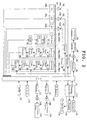
- a film feeding apparatus 10 is used in a photo processing apparatus for scanning and printing an image information of a film such as an APS film.
- the film feeding apparatus 10 includes a film feed controller 12 for controlling the operation of the film feeding apparatus 10.
- the film feed controller 12 corresponds to an assembly of a CPU 14, a ROM 16, a RAM 18 and drivers 20 to 30.
- Programs for various controls of the CPU 14 are stored in the ROM 16, whereas data necessary for the controls by the CPU 14 are temporarily stored in the RAM 18.
- the data to be stored in the RAM 18 include a flag (0 in the presence of the magnetic data, 1 in the absence thereof) representing the presence or absence of a magnetic data 55 (described later) for each frame 51 (described later), and the magnetic data 54 and 55.
- the magnetic data 54, 55 each consist of, e.g. several bytes (one byte is a 8-bit data consisting of a 1-bit parity and a 7-bit data).
- a data on the rotating speed of the film feeding motor 48 (described later) is also stored in the RAM 18. It may be, however, stored in the ROM 16 if being set in advance.
- the film feeding apparatus 10 also includes a feed path 36, which serves as a path for feeding a film 34 contained in a cartridge 32 in directions of arrow X.
- Pairs of feed rollers 42, 44, 46 are arranged substantially at regular intervals along the feed path 36 from a loading side 38 toward an unloading side 40 in such a manner as to hold the film 34 therebetween.
- the pairs of feed rollers 42, 44, 46 are comprised of drive rollers 42a, 44a and 46a arranged at the upper side of the film 34 and pressing rollers 42b, 44b and 46b arranged at the lower side of the film 34, respectively.
- the film feeding motor 48 synchronously drives the feed rollers 42, 44, 46 via a film feed assembly 49, i.e. a transmission means (not shown) to rotate them.
- the film feeding motor 48 is controlled by the CPU 14 such that the film 34 is intermittently fed frame by frame when the film 34 is dispensed from the cartridge 32 and is continuously fed at a constant speed when the film 34 is rewound into the cartridge 32.
- a first film winding speed, a second and subsequent film winding speed which is slower than the first film winding speed, and a film rewinding speed are set as rotating speeds of the film feeding motor 48.
- the reason why the second and subsequent film winding speed is slower than the first one is that the reading frequently ends in failure due to a high recording density of the magnetic data 55.
- the second and subsequent film winding speed may be set faster.
- the rotating speed of the film feeding motor 48 may be selected from several speeds set in advance or may be desirably set by an operator.
- the film feed assembly 49 drives a film take-up assembly 50 for taking up the film 34.
- two perforations 52 are so formed as to correspond to each frame 51 at one end of the film 34 with respect to the widthwise direction thereof.
- the magnetic data 54 includes pieces of information such as print colors and a density correction value; the magnetic data 55 includes pieces of information such as photographing information used in the camera (shutter speed, aperture value, date of photographing, place of photographing, etc.); and the bar code 56 include pieces of information such as an ID number and frame numbers optically imprinted at the manufacturing stage of the film 34. Since the relative positions of the frames 51 with respect to the corresponding perforations 52 is constantly equal, the position of the frame 51 can be confirmed by detecting the perforations 52.
- a film end sensor 58 for detecting the leading end of the film 34 is provided between the cartridge 32 and the pair of feed rollers 42. Between the pairs of feed rollers 42 and 44, there are provided a perforation sensor 60 for detecting the perforations 52 at the one end of the film 34 with respect to its widthwise direction, and bar code sensors 62 for detecting the bar codes 56 at the other end of the film 34 with respect to its widthwise direction. The bar code sensors 62 also detect an end perforation (not shown) to discriminate whether or not the film 34 has been wound up to the last frame 51.
- the film end sensor 58, the perforation sensor 60 and the bar code sensors 62 are comprised of a pair of an LED 58a and a phototransistor 58b, a pair of an LED 60a and a phototransistor 60b and a pair of LED 62a and a phototransistor 62b, respectively.
- the LEDs 58a, 60a, 62a are driven by drivers 22, 24, 26, respectively, and the detection signals of the phototransistors 58b, 60b, 62b are given to the CPU 14.
- a magnetic data reading/writing unit 64 is so provided as to extend in a direction normal to the feed path 36.
- the unit 64 is comprised of a magnetic writing device 66a for the track P1, a magnetic writing device 66b for the track P2, a magnetic reading device 68a for the track P1, a magnetic reading device 68b for the track P2, a magnetic reading device 70a for the track C1 and a magnetic reading device 70b for the track C2.
- a film pressing unit 72 is provided in an exposure position between the pairs of feed rollers 44 and 46.
- the magnetic writing device 66a writes the colors, the density correction value and other information on the film 34, for example, while the film 34 is taken up after printing.
- the data stored in the RAM 18 are converted into an analog signal by a digital-to-analog (D/A) converter 74, and the magnetic data 54 is written on the film 34 by a magnetic write head 78 in accordance with a voltage applied by a driver 76 based on the obtained signal. Since the magnetic writing device 66b is constructed and operated substantially in the same manner as the magnetic writing device 66a, it is neither illustrated nor repetitively described.
- the magnetic reading device 68a reads the magnetic data 54, for example, during scanning.
- the magnetic data 54 written by the film feeding apparatus 10 or the like is read by a magnetic read head 80 and is analog-to-digital (A/D) converted after being amplified by a signal amplifier 82.
- the magnetic data 54 is converted into a data pulse having a rectangular waveform by a peak detector 84, and digitized by a binary detector 84.
- the digitized magnetic data 54 is fed to the CPU 14 and stored in the RAM 18. Since the magnetic reading device 68b is constructed and operated substantially in the same manner as the magnetic reading device 68a, it is neither illustrated nor repetitively described.
- the magnetic reading device 70a reads the magnetic data 55, for example, during the scanning, and its read result is used for a judgment as to whether or not the magnetic data 54 and 55 should be read again.
- the magnetic data 55 written by the camera By using the magnetic data 55 written by the camera in order to judge whether or not the magnetic data 54 and 55 should be read again, whether or not the magnetic data essential for the treatment of the film 34 have been read can be judged.
- the driver 20 sends a signal representing the rotating direction of the film feeding motor 48, i.e. whether the film 34 is to be wound or rewound, to the magnetic reading device 70a, which in turn reads the magnetic data 55 in accordance with the received signal.
- the magnetic data 55 written by the camera is read by a magnetic read head 90 and is A/D converted after being amplified by a signal amplifier 92.
- the magnetic data 55 is converted into a data pulse having a rectangular waveform, digitized by a binary detector 98 after passing through a pulse inverter 96 which operates in response to the output of the driver 20, and sent to a serial-parallel converter 100 which operates in response to the output of the driver 20.
- the digitized magnetic data 55 is sent to the CPU 14 and stored in the RAM 18. Based on the information represented by the magnetic data 55 stored in the RAM 18, the CPU 14 judges whether or not the magnetic data 54 and 55 should be read again. Since the magnetic reading device 70b is constructed and operated substantially in the same manner as the magnetic reading device 70a, it is neither illustrated nor repetitively described.
- the cartridge 32 is formed with a lid opening portion 102 for opening and closing an unillustrated cartridge shading lid (light-lock door) and a cartridge spool shaft driving device 104 for rotating an unillustrated cartridge spool.
- the lid opening portion 102 and the driving device 104 are respectively driven by a lid opening motor 106 and a spool shaft drive motor 108, which are both pulse motors or stepping motors, in order to open the cartridge shading lid and wind the film 34.
- a confirmation sensor 110 comprised of, e.g. a limit switch for confirming whether the film 34 is developed or undeveloped is arranged in a position corresponding to a developed film mark (not shown). Whether the film 34 is developed or undeveloped is detected based on whether or not the limit switch has been pushed by the developed film mark.
- a detection sensor 112 made of, e.g. a limit switch for detecting whether or not the cartridge 32 is mounted in the film feeding apparatus 10. The detection signals of the confirmation sensor 110 and the detection sensor 112 are sent to the CPU 14.
- a printing controller 114 controls a printing assembly 116 and a display 118 in accordance with control signals from the CPU 14.
- the printing assembly 116 prints an image information of the frame 51 located in the exposure position on a printing paper (not shown).
- On the display 118 are displayed the operation results of the CPU 14 and the like. Whether or not the magnetic data 54 and 55 are to be read again is judged in accordance with an input given by an operator by means of a keyboard 120. Further, the rotating speed of the film feeding motor 48 can be set by the keyboard 120.
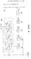
- the magnetic reading device 70a is described with reference to FIGS. 4 to 6.
- the magnetic data 55 is read by the magnetic read head 90, converted into the data pulse having a rectangular waveform by the peak detector 94 after being amplified by the signal amplifier 92, and sent to the pulse inverter 96.
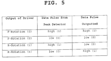
- the pulse inverter 96 is comprised of, e.g. an exclusive or (XOR) circuit, and performs an "exclusive or” operation for the output of the driver 20 representing the rotating direction of the film feeding motor 48 and the data pulse from the peak detector 94 as shown in FIG. 5, and outputs the obtained data pulse to the binary detector 98.
- XOR exclusive or
- the binary detector 98 performs a binary operation (1 or 0) based on to which trailing edge of the film leading end side or of the film rear end side the leading edge (point where low level changes to high level) of the data pulse is closer.
- a binary data "0” is given to a switching circuit 122 of the serial-parallel converter 100 if this leading edge is closer to the film leading end side, whereas a binary data "1” is given thereto if this leading edge is closer to the film rear end side.
- the switching circuit 122 is controlled in accordance with the output of the driver 20 representing the rotating direction of the film feeding motor 48, and sends the binary data to a logic inverter 124 when the film feeding motor 48 is rotated in the reverse direction while sending it directly to a shift register 126 when the film feeding motor 48 is rotated in the forward direction.
- the logic inverter 124 is comprised of, e.g. an inverter to give the binary data to the shift register 126 after inverting it.
- the shift register 126 includes shifting circuits D0 to D15 as shown in FIG. 6 and outputs a 16-bit parallel data after performing a serial-to-parallel conversion or transformation.
- the shifting circuits D0 to D15 are each comprised of, for example, a switching circuit and a flip-flop, and the input ports thereof are switched in accordance with the output of the driver 20 representing the rotating direction of the film feeding motor 48.
- the input position of the binary data (whether the binary data is to be stored from the highest numbered shifting circuit or from the lowest numbered shifting circuit) and a shifting direction are also switched by switching the connection of the shifting circuits as shown in FIGS. 6(a) and 6(b).
- A, B, M, O denote input ports during the forward rotation of the motor 48, input ports during the reverse rotation of the motor 48, the output of the driver 20 representing the rotating direction of the film feeding motor 48 and output ports, respectively.
- the serial-parallel converter 100 sends a corresponding signal to the CPU 14 to notify it.
- the magnetic data includes a start sentinel (SS) and an end sentinel (ES) representing the start and end of each data. Since these bit patterns are determined, the serial-parallel converter 100 checks the bit pattern upon the output of each bit of the binary data. When the leading end of the magnetic data 55 of each frame 51 is detected, it is notified to the CPU 14. Even in the check of the bit pattern, the sentinel to be detected is switched according to the output of the driver 20 representing the rotating direction of the film feeding motor 48.
- the start sentinel SS is detected during the winding of the film (forward rotation)
- the end sentinel ES is detected during the rewinding of the film (reverse rotation).
- the CPU 14 drives the film feeding motor 48 by outputting a command for causing the film feeding motor 48 to rotate in the forward direction and a pulse having a specific cycle to the driver 20 in accordance with the control program stored in the ROM 16. This causes the film feed assembly 49 and the film take-up assembly 50 to operate, thereby feeding the film 34 to a desired position. At this time, if the magnetic data 55 is recorded on the film 34 to be treated, the magnetic polarities of the magnetic data 55 shown in FIG. 7(A) are detected by the magnetic read head 90 passing over the film 34.
- the signal amplifier 92 detects a change in the voltage, amplifies the voltage and outputs the voltage as shown in FIG. 7(B). Based on this voltage, the peak detector 94 outputs low-level signals at peaks in the negative direction while outputting high-level signals at peaks in the positive direction. Accordingly, a data pulse having a rectangular waveform as shown in FIG. 7(C) is obtained and is sent to the pulse inverter 96. Since the film feeding motor 48 is rotated in the forward direction in this case, the given data pulse is sent to the binary detector 98 as it is. The binary detector 98 sends the binary data as shown in FIG. 7(D) to the serial-parallel converter 100.
- the bit shifting direction of the binary data is determined based on the output of the driver 20 before performing a serial-to-parallel conversion.
- a parallel data as shown in FIG. 7(E) is outputted from the serial-parallel converter 100 and stored in the RAM 18 via the CPU 14.
- the CPU 14 drives the film feeding motor 48 by outputting a command for causing the film feeding motor 48 to rotate in the reverse direction and a pulse having a specific cycle to the driver 20 in accordance with the control program stored in the ROM 16. This causes the film feed assembly 49 and the film take-up assembly 50 to operate, thereby rewinding the film 34. At this time, if the magnetic data 55 recorded on the film 34 is read, the magnetic polarities of the magnetic data 55 shown in FIG. 8(A) are detected by the magnetic read head 90 passing over the film 34.
- the signal amplifier 92 detects a change in the voltage, amplifies the voltage and outputs the voltage as shown in FIG. 8(B). Based on this voltage, a data pulse having a rectangular waveform as shown in FIG. 8(C1) is obtained in the peak detector 94 and given to the pulse inverter 96.
- the magnetic polarities of the magnetic data 55 are read in a direction reverse from the one when the film 34 is wound. Accordingly, as shown in FIGS. 7(A) and 8(A), the magnetic polarities at the time of rewinding the film 34 are reverse from those at the time of winding the film 34.
- the output voltage from the signal amplifier 92 and the data pulse from the peak detector 94 are as shown in FIGS. 8(B) and 8(C1), respectively.
- the polarities of the output voltage and the data pulse are inverted since the magnetic polarities are read in the reverse direction. Accordingly, in order to enable a binary conversion (binary transformation), the polarity of the data pulse from the peak detector 94 is inverted by the pulse inverter 96 before the binary conversion to generate a data pulse as shown in FIG. 8(C2).
- the binary detector 98 applies a binary conversion to this data pulse to obtain a binary data shown in FIG. 8(D1), which is then sent to the serial-parallel converter 100.
- the binary data shown in FIG. 8(D1) is a data having polarities reverse from those of an original data which should be generated and, therefore, should be restored to the original data.
- the binary data shown in FIG. 8(D1) is inverted by the logic inverter 124 of the serial-parallel converter 100 to generate a binary data shown in FIG. 8(D2), which is then sent to the shift register 126.
- the binary data shown in FIG. 8(D2) is the same as the one obtained by rearranging the binary data (FIG. 7(D)), which was obtained at the time of winding the film 34 (forward rotation), from behind.
- the bit shifting direction of the binary data from the binary detector 98 is determined based on the output of the driver 20 before performing a serial-parallel conversion.
- a parallel data as shown in FIG. 8(E) is outputted by reversing the bit shifting direction of the binary data and stored in the RAM 18 via the CPU 14.
- the magnetic data 55 can be satisfactorily read by changing the reading operation depending upon whether the film 34 is wound or rewound.
- the magnetic reading device 70a is described above. It should be appreciated that the magnetic reading device 70b is similarly constructed and operated.
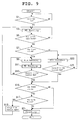
- the magnetic data reading operation of the film feed apparatus 10 is described with reference to FIG. 9.
- Step S1 whether or not the cartridge 32 containing the film 34 is set is detected by the detection sensor 112 (Step S1).
- the apparatus 10 waits on standby unless the cartridge 32 is set, whereas the magnetic data reading operation as described later is performed (Step S3) if the cartridge 32 is set.
- Step S5 whether or not the film 34 has been wound to the last frame 51 is discriminated.
- the magnetic data continue to be read until the film 34 is wound to the last frame 51. If the film is wound to the last frame 51, whether or not there is any frame 51 whose magnetic data 55 has not been read yet is discriminated by an operation to be described later.
- Step S9 If there is a frame 51 whose magnetic data 55 has not been read yet, the film 34 is rewound (Step S9). At this time, the film 34 is continuously fed. Then, the magnetic data reading operation is performed again (Step S11) and whether or not the film 34 has been rewound to its leading end is discriminated by the perforation sensor 60 (Step S13). This flow returns to Step S9 unless the film 34 has not been rewound yet to its leading end, and whether or not there is any frame 51 whose magnetic data 55 has not been read yet is discriminated (Step S15) if the film 34 is rewound to its leading end.
- Step S17 If there is still a frame 51 whose magnetic data 55 has not been read yet, whether or not the magnetic data 55 should be read again is judged (Step S17). At this time, a notification that there is a frame 51 whose magnetic data 55 has not been read yet is given to the operator by means of the display 118 or the like in order to question him whether or not the magnetic data 55 should be reread. If the operator gives a command to reread the magnetic data 55 by means of the keyboard 120, the feeding speed of the film 34 is changed as set by the operator or automatically (Step S19) and this flow returns to Step S3 to reread the magnetic data 55.
- Step S21 If the operator gives no such command as above in Step S17, the magnetic data reading operation ends after a printing operation is performed (Step S21).
- the magnetic data 55 is reread as long as the operator continues to give a command to reread.
- Step S15 If, in Step S15, there is no frame 51 whose magnetic data 55 has not been read yet, Step S21 follows.
- Step S7 if, in Step S7, there is no frame 51 whose magnetic data has not been read, the film 34 is rewound (Step S23). After the film 34 is rewound to its leading end (YES in Step S25), Step S15 follows. In this case, the magnetic data reading operation ends after the printing operation is performed without rereading the magnetic data 55.
- magnetic data 54 is also read during the magnetic data reading and rereading operations in FIG. 9.
- Step S3 the detail of the operation in Step S3 is described with reference to FIG. 10.
- Step S31 the film 34 is wound by one frame (Step S31), and the magnetic data 55 is read and stored in the RAM 18 (Step S33). Then, whether or not the film 34 has been wound by one frame is discriminated (Step S35), and this flow returns to Step S31 if not.
- Step S37 whether or not the magnetic data 55 is present in the RAM 18 is discriminated. If the magnetic data 55 is present, whether or not the magnetic data 55 has missing part(s) or inverted bit(s) or inverted parity bit is discriminated (Step S39). If the magnetic data 55 has neither a missing part nor an inverted bit nor an inverted parity bit, the presence of the magnetic data is judged and a flag in the RAM 18 indicative thereof is set in the RAM 18 (Step S41) and this flow ends.
- Step S43 whether or not the magnetic data 55 is restorable is discriminated. Since the magnetic data 55 is a 8-bit data comprised of a 1-bit party and a 7-bit data, whether or not the magnetic data 55 is restorable can be judged by, for example, judging whether or not an error is found in one or less bit using a known error detecting method.
- Step S41 If restorable, the magnetic data 55 is restored using a known error correcting method, and then Step S41 follows.
- Step S45 if the magnetic data 55 is absent in Step S37 or if the magnetic data 55 is judged not to be restorable in Step S43, the absence of the magnetic data is judged and the flag in the RAM 18 indicative thereof is set (Step S45) and this flow ends.
- the magnetic data 55 is read frame by frame while the film 34 is intermittently wound frame by frame. Thereafter, the presence or absence of the magnetic data 55 is judged for each frame 51. Such an operation can deal with a case where the magnetic data 55 is mistakenly read.
- Step S11 The magnetic data reading operation at the time of the film rewinding in Step S11 is performed by the operations of Steps S33 to S45 excluding Step S31 of FIG. 10. At this time, this flow returns to Step S33 if the discrimination result in Step S35 is negative. In this way, when the film is rewound, the magnetic data 55 of the respective frames 51 of the film 35 being continuously fed are successively read and, then, the presence or absence of the magnetic data 55 is judged for each frame 51.
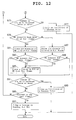
- Steps S7 and S15 are described with reference to FIGS. 11 and 12.
- Step S51 referring to the flag in the RAM 18 for each frame 51, whether or not the magnetic data 55 has been properly read from the track C1 of the first frame, i.e. the magnetic data 55 is present in the track C1 of the first frame (Step S51).
- the presence of the magnetic data 55 in the track C1 of the first frame is stored in the RAM 18 (Step S53) if the magnetic data 55 has been properly read, whereas the absence thereof is stored in the RAM 18 (Step S55) if the magnetic data 55 has not been properly read.
- Step S57 whether or not the magnetic data 55 has been properly read from the track C2 of the first frame is discriminated.
- the presence of the magnetic data 55 in the track C2 of the first frame is stored in the RAM 18 (Step S59) if the magnetic data 55 has been properly read, whereas the absence thereof is stored in the RAM 18 (Step S61) if the magnetic data 55 has not been properly read.
- Step S63 whether or not the magnetic data 55 has been properly read from the track C1 of the succeeding frame is discriminated. If the magnetic data 55 has been properly read, the presence of the magnetic data 55 in the track C1 of the succeeding frame is stored in the RAM 18 (Step S65) and whether or not the magnetic data 55 is present for the previous frame 51 is discriminated (Step S67). If the magnetic data 55 is absent in the previous frame 51, a change in the presence/absence of the magnetic data 55 from the previous frame 51 is stored in the RAM 18 (Step S69).
- Step S63 if the magnetic data 55 is discriminated not to have been properly read in Step S63, the absence of the magnetic data 55 in the track C1 of the succeeding frame 51 is stored in the RAM 18 (Step S71) and whether or not the magnetic data 55 is present for the previous frame 51 is discriminated (Step S73). Step S69 follows if the magnetic data 55 is present for the previous frame 51.
- Step S67 If YES in Step S67, if NO in Step S73, or after the operation in Step S69, whether or not the change in the presence/absence of the magnetic data 55 in the track C1 from the previous frame 51 has occurred twice or more is discriminated (Step S67) as shown in FIG. 12. If this change has occurred twice or more, it is judged that a reading error has occurred for the frame 51 having no magnetic data 55 (Step S77) and this subroutine ends.
- Step S79 whether or not the magnetic data 55 has been properly read from the track C2 of the succeeding frame 51 is discriminated. If the magnetic data has been properly read, the presence of the magnetic data 55 in the track C2 of the succeeding frame 51 is stored in the RAM 18 (Step S81) and whether or not the magnetic data 55 is present for the previous frame 51 is discriminated (Step S83). If the magnetic data 55 is absent in the previous frame 51, a change in the presence/absence of the magnetic data 55 from the previous frame 51 is stored in the RAM 18 (Step S85).
- Step S85 follows if the magnetic data 55 is present for the previous frame 51.
- Step S91 If YES in Step S83, if NO in Step S89, or after the operation in Step S85, whether or not the change in the presence/absence of the magnetic data 55 in the track C2 from the previous frame 51 has occurred twice or more is discriminated (Step S91). If this change has occurred twice or more, it is judged that a reading error has occurred for the frame 51 having no magnetic data 55 (Step S93) and this flow ends.
- Step S95 whether or not the check has been made up to the last frame 51. If not, this flow returns to Step S63. If the check has been made up to the last frame 51, all the magnetic data 55 are judged to have been successfully read upon the assumption that no magnetic data 55 was recorded for the frame 51 having no magnetic data 55 (Step S97) and this flow ends.
- the read states of the magnetic data 55 shown in FIGS. 13(a) to 13(d) are not judged as reading errors.
- the magnetic data 55 was read from none of the frames of the film 34 as shown in FIG. 13(a), it is judged that no magnetic data 55 is recorded on the film 34 and no reading error occurred. If the magnetic data 55 were read from all of the frames of the film 34 as shown in FIG. 13(b), it is judged that exposure was made from the first frame to the last frame of the film 34 and no reading error occurred. If the magnetic data 55 were read from the first frame to an intermediate frame of the film 34 as shown in FIG. 13(c), it is judged that exposure was made up to the intermediate frame of the film 34 and no reading error occurred. If the magnetic data 55 were read from an intermediate frame to the last frame of the film 34 as shown in FIG. 13(d), it is judged that exposure was made to the film 34 from the intermediate frame and no reading error occurred.
- the reading error is judged to have occurred if the read state of the magnetic data 55 changes twice or more between the first and last frames of the film 34 as shown in FIGS. 13(e) and 13(f).
- this film feeding apparatus 10 if there is a frame 51 whose magnetic data 55 failed to be read while the film was wound during the scanning, the magnetic data 55 are automatically read also during the rewinding of the film after the scanning. In this way, a probability of reading the magnetic data 55 is improved by reading the magnetic data 55 also during the rewinding of the film after changing the reading state by reversing the feeding direction of the film 34. The need for rereading the magnetic data 55 by performing the scanning again becomes remarkably lower. Therefore, operability can be improved.
- the magnetic data 55 are read by intermittently feeding the film 34 frame by frame. During the rewinding of the film 34, the magnetic data 55 are continuously read without stopping the film feeding motor 48. Since the magnetic data 55 can be read with the reading state changed. Thus, the reading rate of the magnetic data 55 can be improved.
- the magnetic data 55 recorded at a considerably high or low recording density can also be dealt with.
- the reliability of the apparatus is improved by eliminating the need for reading the magnetic data 55 again and again.
- the photographed images are less likely to be finished into prints different from a photographer's intention (e.g. different print size), thereby refraining troubles from occurring.
- the magnetic data 55 are read also during the rewinding of the film 34 if there is a frame 51 whose magnetic data 55 was not read during the first winding of the film, the invention is not limited to this.
- the film 34 is rewound without reading the magnetic data 55 and the magnetic data 55 of the film 34 may be read during the second winding of the film after the feeding speed of the film 34 is changed.
- This experiment was conducted by a method comprising the steps of (A) after reading the magnetic data 55 during the winding of the film for the scanning, (B) reading the magnetic data 55 during the rewinding of the film, (C) winding the film after changing the feeding speed to reread the magnetic data 55, and (D) rereading the magnetic data 55 during the rewinding of the film.
- the reading rates of the magnetic data 55 were measured after the completion of the respective operation steps.
- a reading rate 1 ⁇ of the magnetic data after the completion of the operation step (A), a reading rate 2 ⁇ thereof after the completion of the operation step (B) and a reading rate 3 ⁇ thereof after the completion of the operation step (D) are shown in TABLE-1.
- This experiment was conducted by a method comprising the steps of (A) rewinding the film after reading the magnetic data 55 during the winding of the film for the scanning, and (B) winding the film after changing the feeding speed to thereby reread the magnetic data 55.
- a reading rate 1 ⁇ of the magnetic data after the completion of the operation step (A) and a reading rate 2 ⁇ thereof after the completion of the operation step (B) were measured. The measurement result is shown in TABLE-2.
- the reading rate is improved by rereading the magnetic data 55 after changing the feeding speed of the film.
- the printing controller 114 and the printing assembly 116 shown in FIG. 2 and Step S21 shown in FIG. 9 may be omitted.
- the operability and reliability of the apparatus can be improved since the reading rate of the magnetic data is improved.
Landscapes
- Physics & Mathematics (AREA)
- General Physics & Mathematics (AREA)
- Engineering & Computer Science (AREA)
- Computer Hardware Design (AREA)
- Projection-Type Copiers In General (AREA)
- Camera Data Copying Or Recording (AREA)
Applications Claiming Priority (2)
| Application Number | Priority Date | Filing Date | Title |
|---|---|---|---|
| JP12422598 | 1998-04-17 | ||
| JP10124225A JPH11305322A (ja) | 1998-04-17 | 1998-04-17 | フィルム搬送装置およびフィルム搬送方法 |
Publications (3)
| Publication Number | Publication Date |
|---|---|
| EP0950919A2 true EP0950919A2 (de) | 1999-10-20 |
| EP0950919A3 EP0950919A3 (de) | 2003-10-08 |
| EP0950919B1 EP0950919B1 (de) | 2006-08-02 |
Family
ID=14880101
Family Applications (1)
| Application Number | Title | Priority Date | Filing Date |
|---|---|---|---|
| EP99106500A Expired - Lifetime EP0950919B1 (de) | 1998-04-17 | 1999-03-30 | Vorrichtung und Verfahren zum Lesen magnetisch gespeicherter Daten von einem photographischen Film beim Spulen |
Country Status (4)
| Country | Link |
|---|---|
| US (1) | US6288770B1 (de) |
| EP (1) | EP0950919B1 (de) |
| JP (1) | JPH11305322A (de) |
| DE (1) | DE69932559T2 (de) |
Family Cites Families (8)
| Publication number | Priority date | Publication date | Assignee | Title |
|---|---|---|---|---|
| US5130728A (en) * | 1989-10-27 | 1992-07-14 | Nikon Corporation | Information recordable camera |
| JPH0447568A (ja) * | 1990-06-15 | 1992-02-17 | Teac Corp | 磁気テープ装置におけるデータ読み取り方法 |
| JPH0496036A (ja) * | 1990-08-14 | 1992-03-27 | Canon Inc | 磁気記憶部付きフィルムの情報読出装置 |
| KR100187383B1 (ko) * | 1994-03-25 | 1999-05-15 | 니시모토 강이치 | 사진필름 처리장치 및 그 제어방법 |
| JPH086127A (ja) * | 1994-06-15 | 1996-01-12 | Canon Inc | カメラ |
| JPH08334825A (ja) * | 1995-06-09 | 1996-12-17 | Minolta Co Ltd | フィルムの未露光コマ判別装置 |
| US6055382A (en) * | 1996-01-31 | 2000-04-25 | Minolta Co., Ltd. | Apparatus having a judging device whether a film frame is exposed or not |
| US6026249A (en) * | 1996-10-01 | 2000-02-15 | Fuji Photo Film Co., Ltd. | Device for detecting the presence of recorded information on a magnetic film by comparing an envelope waveform with a threshold level |
-
1998
- 1998-04-17 JP JP10124225A patent/JPH11305322A/ja active Pending
-
1999
- 1999-03-30 DE DE69932559T patent/DE69932559T2/de not_active Expired - Fee Related
- 1999-03-30 EP EP99106500A patent/EP0950919B1/de not_active Expired - Lifetime
- 1999-03-31 US US09/281,960 patent/US6288770B1/en not_active Expired - Fee Related
Also Published As
| Publication number | Publication date |
|---|---|
| JPH11305322A (ja) | 1999-11-05 |
| EP0950919B1 (de) | 2006-08-02 |
| EP0950919A3 (de) | 2003-10-08 |
| DE69932559T2 (de) | 2007-08-09 |
| US6288770B1 (en) | 2001-09-11 |
| DE69932559D1 (de) | 2006-09-14 |
Similar Documents
| Publication | Publication Date | Title |
|---|---|---|
| RU1836651C (ru) | Полоса фотопленки и система окончательной отделки фотоснимка | |
| US5344730A (en) | Method of recording information on a photographic film | |
| JPH01102539A (ja) | 写真フイルムのコマ番号判別方法 | |
| US4972068A (en) | Retrieval apparatus readily adaptable for use with various types of recording media | |
| KR0147815B1 (ko) | 필름상의 전용 자기 트랙들을 사용하여 사진처리하는 필름-비디오 플레이어 | |
| EP0950919B1 (de) | Vorrichtung und Verfahren zum Lesen magnetisch gespeicherter Daten von einem photographischen Film beim Spulen | |
| US6229592B1 (en) | Negative film with identification number, and photographic printing apparatus | |
| JPH04273238A (ja) | 情報入出力システムを搭載したカメラ | |
| JP2979978B2 (ja) | 写真焼付け装置における位置情報決定方法および写真焼付け装置 | |
| EP0890871B1 (de) | Verfahren und Gerät zur Beurteilung eines Fehlers bei der Lektüre von auf fotografischen Film aufgezeichneten Daten | |
| JP3573518B2 (ja) | 静止画画面数照合装置及びその照合方法 | |
| JPH0825763A (ja) | 印字異常検知方法 | |
| JPH11295821A (ja) | フィルム搬送装置およびフィルム搬送方法 | |
| JP2001330906A (ja) | 写真フィルムの記録情報を読み取り可能とした写真処理装置 | |
| JPS63177120A (ja) | デ−タ写し込み装置 | |
| JPH0545717A (ja) | 情報記録方法及びカメラ | |
| JPH01115675A (ja) | イメージスキャナ装置 | |
| JP2007156305A (ja) | 画像形成装置 | |
| JPH09218467A (ja) | 写真システム | |
| JPH07314834A (ja) | 画像形成装置 | |
| JPH0876233A (ja) | 磁気記録方法 | |
| JP2000267200A (ja) | 裏焼き検出方法および写真処理装置 | |
| JPH05341389A (ja) | フィルムバーコード検出方法 | |
| JP2001290223A (ja) | トラブル検出機構と写真処理装置 | |
| JPH07333815A (ja) | 写真フィルムからの情報読取装置 |
Legal Events
| Date | Code | Title | Description |
|---|---|---|---|
| PUAI | Public reference made under article 153(3) epc to a published international application that has entered the european phase |
Free format text: ORIGINAL CODE: 0009012 |
|
| 17P | Request for examination filed |
Effective date: 19990422 |
|
| AK | Designated contracting states |
Kind code of ref document: A2 Designated state(s): AT BE CH CY DE DK ES FI FR GB GR IE IT LI LU MC NL PT SE |
|
| AX | Request for extension of the european patent |
Free format text: AL;LT;LV;MK;RO;SI |
|
| PUAL | Search report despatched |
Free format text: ORIGINAL CODE: 0009013 |
|
| RIC1 | Information provided on ipc code assigned before grant |
Ipc: 7G 11B 15/087 B Ipc: 7G 11B 15/02 B Ipc: 7G 11B 15/20 B Ipc: 7G 03B 27/62 A |
|
| AK | Designated contracting states |
Kind code of ref document: A3 Designated state(s): AT BE CH CY DE DK ES FI FR GB GR IE IT LI LU MC NL PT SE |
|
| AX | Request for extension of the european patent |
Extension state: AL LT LV MK RO SI |
|
| 17Q | First examination report despatched |
Effective date: 20040213 |
|
| AKX | Designation fees paid |
Designated state(s): DE FR GB |
|
| GRAP | Despatch of communication of intention to grant a patent |
Free format text: ORIGINAL CODE: EPIDOSNIGR1 |
|
| GRAS | Grant fee paid |
Free format text: ORIGINAL CODE: EPIDOSNIGR3 |
|
| GRAA | (expected) grant |
Free format text: ORIGINAL CODE: 0009210 |
|
| AK | Designated contracting states |
Kind code of ref document: B1 Designated state(s): DE FR GB |
|
| REG | Reference to a national code |
Ref country code: GB Ref legal event code: FG4D |
|
| REF | Corresponds to: |
Ref document number: 69932559 Country of ref document: DE Date of ref document: 20060914 Kind code of ref document: P |
|
| EN | Fr: translation not filed | ||
| PLBE | No opposition filed within time limit |
Free format text: ORIGINAL CODE: 0009261 |
|
| STAA | Information on the status of an ep patent application or granted ep patent |
Free format text: STATUS: NO OPPOSITION FILED WITHIN TIME LIMIT |
|
| 26N | No opposition filed |
Effective date: 20070503 |
|
| GBPC | Gb: european patent ceased through non-payment of renewal fee |
Effective date: 20070330 |
|
| PG25 | Lapsed in a contracting state [announced via postgrant information from national office to epo] |
Ref country code: GB Free format text: LAPSE BECAUSE OF NON-PAYMENT OF DUE FEES Effective date: 20070330 Ref country code: FR Free format text: LAPSE BECAUSE OF FAILURE TO SUBMIT A TRANSLATION OF THE DESCRIPTION OR TO PAY THE FEE WITHIN THE PRESCRIBED TIME-LIMIT Effective date: 20070511 |
|
| PGFP | Annual fee paid to national office [announced via postgrant information from national office to epo] |
Ref country code: DE Payment date: 20080407 Year of fee payment: 10 |
|
| PG25 | Lapsed in a contracting state [announced via postgrant information from national office to epo] |
Ref country code: FR Free format text: LAPSE BECAUSE OF FAILURE TO SUBMIT A TRANSLATION OF THE DESCRIPTION OR TO PAY THE FEE WITHIN THE PRESCRIBED TIME-LIMIT Effective date: 20060802 |
|
| PG25 | Lapsed in a contracting state [announced via postgrant information from national office to epo] |
Ref country code: DE Free format text: LAPSE BECAUSE OF NON-PAYMENT OF DUE FEES Effective date: 20091001 |