EP0964155A2 - Soupape de contrÔle de déplacement utilisée dans un compresseur à capacité variable - Google Patents
Soupape de contrÔle de déplacement utilisée dans un compresseur à capacité variable Download PDFInfo
- Publication number
- EP0964155A2 EP0964155A2 EP99110771A EP99110771A EP0964155A2 EP 0964155 A2 EP0964155 A2 EP 0964155A2 EP 99110771 A EP99110771 A EP 99110771A EP 99110771 A EP99110771 A EP 99110771A EP 0964155 A2 EP0964155 A2 EP 0964155A2
- Authority
- EP
- European Patent Office
- Prior art keywords
- chamber
- pressure
- valve body
- valve
- displacement control
- Prior art date
- Legal status (The legal status is an assumption and is not a legal conclusion. Google has not performed a legal analysis and makes no representation as to the accuracy of the status listed.)
- Withdrawn
Links
- 238000006073 displacement reaction Methods 0.000 title claims abstract description 85
- 230000007246 mechanism Effects 0.000 claims abstract description 66
- 238000007789 sealing Methods 0.000 claims description 9
- 238000000034 method Methods 0.000 claims description 8
- 230000004044 response Effects 0.000 claims description 8
- 238000003780 insertion Methods 0.000 claims description 4
- 230000037431 insertion Effects 0.000 claims description 4
- 239000012530 fluid Substances 0.000 claims 6
- 230000001154 acute effect Effects 0.000 claims 2
- 230000004075 alteration Effects 0.000 abstract description 6
- 238000004891 communication Methods 0.000 description 16
- 230000008859 change Effects 0.000 description 9
- 230000005540 biological transmission Effects 0.000 description 4
- 238000010276 construction Methods 0.000 description 4
- 230000002093 peripheral effect Effects 0.000 description 4
- 238000004378 air conditioning Methods 0.000 description 1
- 230000006835 compression Effects 0.000 description 1
- 238000007906 compression Methods 0.000 description 1
- 230000003247 decreasing effect Effects 0.000 description 1
- 230000006872 improvement Effects 0.000 description 1
Images

Classifications
-
- F—MECHANICAL ENGINEERING; LIGHTING; HEATING; WEAPONS; BLASTING
- F04—POSITIVE - DISPLACEMENT MACHINES FOR LIQUIDS; PUMPS FOR LIQUIDS OR ELASTIC FLUIDS
- F04B—POSITIVE-DISPLACEMENT MACHINES FOR LIQUIDS; PUMPS
- F04B27/00—Multi-cylinder pumps specially adapted for elastic fluids and characterised by number or arrangement of cylinders
- F04B27/08—Multi-cylinder pumps specially adapted for elastic fluids and characterised by number or arrangement of cylinders having cylinders coaxial with, or parallel or inclined to, main shaft axis
- F04B27/14—Control
- F04B27/16—Control of pumps with stationary cylinders
- F04B27/18—Control of pumps with stationary cylinders by varying the relative positions of a swash plate and a cylinder block
- F04B27/1804—Controlled by crankcase pressure
- F04B2027/1809—Controlled pressure
- F04B2027/1813—Crankcase pressure
-
- F—MECHANICAL ENGINEERING; LIGHTING; HEATING; WEAPONS; BLASTING
- F04—POSITIVE - DISPLACEMENT MACHINES FOR LIQUIDS; PUMPS FOR LIQUIDS OR ELASTIC FLUIDS
- F04B—POSITIVE-DISPLACEMENT MACHINES FOR LIQUIDS; PUMPS
- F04B27/00—Multi-cylinder pumps specially adapted for elastic fluids and characterised by number or arrangement of cylinders
- F04B27/08—Multi-cylinder pumps specially adapted for elastic fluids and characterised by number or arrangement of cylinders having cylinders coaxial with, or parallel or inclined to, main shaft axis
- F04B27/14—Control
- F04B27/16—Control of pumps with stationary cylinders
- F04B27/18—Control of pumps with stationary cylinders by varying the relative positions of a swash plate and a cylinder block
- F04B27/1804—Controlled by crankcase pressure
- F04B2027/1822—Valve-controlled fluid connection
- F04B2027/1827—Valve-controlled fluid connection between crankcase and discharge chamber
-
- F—MECHANICAL ENGINEERING; LIGHTING; HEATING; WEAPONS; BLASTING
- F04—POSITIVE - DISPLACEMENT MACHINES FOR LIQUIDS; PUMPS FOR LIQUIDS OR ELASTIC FLUIDS
- F04B—POSITIVE-DISPLACEMENT MACHINES FOR LIQUIDS; PUMPS
- F04B27/00—Multi-cylinder pumps specially adapted for elastic fluids and characterised by number or arrangement of cylinders
- F04B27/08—Multi-cylinder pumps specially adapted for elastic fluids and characterised by number or arrangement of cylinders having cylinders coaxial with, or parallel or inclined to, main shaft axis
- F04B27/14—Control
- F04B27/16—Control of pumps with stationary cylinders
- F04B27/18—Control of pumps with stationary cylinders by varying the relative positions of a swash plate and a cylinder block
- F04B27/1804—Controlled by crankcase pressure
- F04B2027/184—Valve controlling parameter
- F04B2027/1845—Crankcase pressure
-
- F—MECHANICAL ENGINEERING; LIGHTING; HEATING; WEAPONS; BLASTING
- F04—POSITIVE - DISPLACEMENT MACHINES FOR LIQUIDS; PUMPS FOR LIQUIDS OR ELASTIC FLUIDS
- F04B—POSITIVE-DISPLACEMENT MACHINES FOR LIQUIDS; PUMPS
- F04B27/00—Multi-cylinder pumps specially adapted for elastic fluids and characterised by number or arrangement of cylinders
- F04B27/08—Multi-cylinder pumps specially adapted for elastic fluids and characterised by number or arrangement of cylinders having cylinders coaxial with, or parallel or inclined to, main shaft axis
- F04B27/14—Control
- F04B27/16—Control of pumps with stationary cylinders
- F04B27/18—Control of pumps with stationary cylinders by varying the relative positions of a swash plate and a cylinder block
- F04B27/1804—Controlled by crankcase pressure
- F04B2027/184—Valve controlling parameter
- F04B2027/1859—Suction pressure
Definitions
- the present invention relates to a displacement control valve mechanism of a variable displacement compressor used in an air conditioner for an automobile or the like and a variable displacement compressor using such a mechanism.
- variable displacement compressors have been used in air conditioners for automobiles and such a compressor is disclosed in Japanese Patent Publication (JP-B) No. 4-74549.
- JP-B Japanese Patent Publication
- the variable displacement compressor is disclosed which has its outer frame formed by a cylinder block provided with a plurality of cylinder bores, a front housing mounted on one end of the cylinder block, and a rear housing mounted on the other end of the cylinder block while encasing a valve plate device therein.
- a crank chamber is defined between one end of the front housing and one end of the cylinder block.
- a drive shaft is disposed in the crank chamber.
- a swash plate mechanism is disposed around the drive shaft.
- the swash plate mechanism includes a tilting plate, a drive plate, and a rotor. In the swash Plate mechanism, the drive plate carries out a tilting movement. The drive plate comes into contact with the tilting plate.
- the rotor is connected to the drive plate for driving the drive plate.
- a discharge chamber and a suction chamber are defined in the rear housing.
- pistons are disposed which are connected to the periphery of one end of the tilting plate through piston rods.
- This conventional type of displacement control valve mechanism is called a pressure control valve of an inner control type.
- a pressure sensing space and a valve chamber portion are defined in the casing and a pressure sensing member is disposed in the pressure sensing space.
- the pressure sensing space and a suction chamber are communicated with each other.
- the valve chamber portion is communicated with a discharge chamber by way of a communication hole which is communicated with the discharge chamber and a communication chamber which ensues the communication hole.
- a through hole is communicated with the crank chamber.
- the pressure sensing member accommodated in the pressure sensing space senses a pressure of the suction chamber and vertically moves a valve body of the valve chamber portion in response to the pressure of the suction chamber. Furthermore, the pressure sensing member adjusts an opened degree of a first passage extending from the discharge chamber to the crank chamber.
- the pressure control characteristics in the suction chamber of the displacement control valve mechanism is designed such that the pressure in the suction chamber (hereinafter called simply as suction chamber pressure) is changed in response to the pressure in the discharge chamber (hereinafter called simply as discharge chamber pressure).
- control characteristics of the suction chamber pressure is determined to have the optimum characteristics in a condition where the compressor is mounted on a vehicle. Accordingly, the optimum characteristics varies depending on vehicles so that the displacement control valve mechanism which has several kinds of control characteristics of the suction chamber pressure becomes necessary.
- the characteristic i.e., the characteristic curve representing the realizable relationship between the suction chamber pressure and the discharge chamber pressure
- the characteristic is changed by shifting it up and down by adjusting the amount of displacement of a spring inside a bellows portion of the pressure sensing member with an adjustment screw.
- the characteristics is optimized by changing the amount of variation of pressure in the suction chamber relative to the pressure in the discharge chamber.
- the conventional structure necessitates the change of the seal area of a valve body made of a ball valve or the effective area of the bellows portion.
- the provision is constructed such that the amount of variation of the suction chamber pressure is changed relative to the discharge chamber pressure for changing the control characteristics of the suction chamber pressure without changing the seal area of the valve body and the design condition of the bellows portion side.
- the valve mechanism in the displacement control valve mechanism of the variable displacement compressor wherein the valve mechanism is mounted in a compressor including a discharge chamber, a suction chamber and a crank chamber, the valve mechanism comprises a valve chamber communicated with the discharge chamber, pressure sensing means which detects the fluctuation of pressure of either one of the suction chamber or the crank chamber and carries out an extending or retracting movement, and a valve body which is disposed in the valve chamber and is opened or closed in response to the extending or retracting movement for adjusting the valve travel of a first passage leading from the discharge chamber to the crank chamber, and a piston stroke is controlled by adjusting the pressure of the crank chamber, the improvement is characterized in that the displacement control valve mechanism further includes a pressure chamber which is defined as a neighboring chamber of the valve chamber, a second passage which makes the pressure chamber and the crank chamber communicate with each other, and a valve guide portion which defines the pressure chamber and said valve chamber and supports the valve body while allowing an insertion of the valve body therein, and the valve body has one end
- the sealing cross-sectional area formed on the other end of the valve body is a pressure receiving surface and comes into contact with a valve seat for the valve body.
- the valve body in the displacement control valve mechanism of the variable displacement compressor, has a cylindrical shape and is formed such that the other end the valve body has a larger cross-sectional area than one end of the valve body.
- variable displacement compressor which uses the above-mentioned displacement control valve mechanism of the variable displacement compressor is provided.
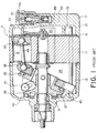
- Fig. 1 is a view showing a variable displacement compressor disclosed in the Japanese Patent Publication (JP-B) No. Hei 4-74549.
- the variable displacement compressor 7 has its outer frame formed by a cylinder block 11 provided with a plurality of cylinder bores 9 arranged in a concentric manner, a front housing 13 mounted on one end of the cylinder block 11 and a rear housing 17 mounted on the other end of the cylinder block 11 while encasing a valve plate device 15 therein.
- the valve plate device 15 is mounted on the other end of the cylinder block 11 in an abutting manner.
- a discharge chamber 25 and a suction chamber 27 are defined by means of the valve plate device 15, an inner wall 19, an outer wall 21 and a bottom wall 23.
- a crank chamber 29 is defined between one end of the front housing 13 and one end of the cylinder block 11.
- a drive shaft 31 is disposed in and passes through the front housing 13 and a swash plate mechanism 33 is disposed around the drive shaft 31.
- the swash plate mechanism 33 includes a tilting plate 35 which carries out in a direction along the drive shaft 31 a tilting movement with a large movement at the outer peripheral portion thereof and a small movement at the inner side thereof, a drive plate 37 which comes into contact with the tilting plate 35, and a rotor 39 which drives the drive plate 37.
- the rotor 39 and the drive plate 37 are constructed such that they are interlocked by means of a drive transmission member such as a guide pin 41.
- numeral 43, 45 respectively indicate thrust bearings.
- Pistons 47 are disposed in the cylinder bores 9 of the cylinder block 11 in such a manner that the pistons 47 are slidably movable along the central axes of the cylinder bores 9.
- the pistons 47 and the peripheral portion of one end of the tilting plate 35 are connected by means of piston rods 49 which are provided with spherical portions at both ends thereof.
- a displacement control valve mechanism 51 is mounted in the bottom wall 23 of the other end of the rear housing 17.
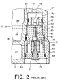
- the displacement control valve mechanism 51 is shown in an upside-down relationship relative to the displacement control valve mechanism 51 shown in Fig. 1.
- the displacement control valve mechanism 51 includes a casing body 53 and a cap-shaped lid member 55 which is mounted on one end of the casing body 53.
- a recess is formed in an axially inward direction to define a valve chamber portion 59, while in one end of the casing body 53, a recess is formed and a pressure sensing space 57 is defined between this recess and the lid member 55.
- a through hole 61 is formed between the pressure sensing space 57 and the valve chamber portion 59, which are communicated with each other in a longitudinal direction.
- Another through hole 63 is formed in the casing body 53 in a direction perpendicular to the direction of the through hole 61 and this through hole 63 is communicated with a space 65 surrounding the casing body 53.
- valve body 67 is disposed and the valve body 67 is biased toward one end of the through hole 61 or in a downward direction in Fig. 2 by means of a spiral spring 69.
- a pressure sensing member 71 is disposed inside the pressure sensing space 57.
- the pressure sensing member 71 includes a support member 73, an adjustment screw portion 75, a bellows portion 77 disposed between these two elements, and an inner compression spring 79 disposed inside the bellows portion 77.
- a transmission rod 81 is disposed in the through hole 61 for making the support member 73 and the valve body 67 communicated with each other.
- the adjustment screw portion 75 adjusts the displacement position of the bellows 77 in a longitudinal direction (in an up-and-down direction in the drawing).
- the pressure sensing space 57 and the suction chamber 27 are communicated by way of a communication hole 83, while the valve chamber portion 59 is communicated with the discharge chamber 25 by way of a communication hole 85 which is communicated with the discharge chamber 25 and an ensuing communication chamber 87. Furthermore, the through hole 63 is communicated with the crank chamber 29 by way of the space portion 65 and a communication passage 89.
- the bellows portion 77 is accommodated in the pressure sensing space 57 and is a so-called a pressure control valve of an inner control type which detects the pressure in the suction chamber 27 and moves the valve body 67 up and down in response to the pressure in the suction chamber 27 and adjusts the valve travel of a first passage extending from the discharge chamber 25 to the crank chamber 29.
- the above formula (4) expresses the pressure control characteristics of the inside of the suction chamber of the displacement control valve mechanism. As shown in Fig. 3, this characteristics makes the pressure Ps inside the suction chamber (hereinafter called simply suction chamber pressure) change linearly in response to the pressure Pd inside the discharge chamber (hereinafter called simply discharge chamber pressure).
- the control characteristics of the suction chamber pressure is determined to have the optimum characteristics in a condition where the compressor is mounted on a specific vehicle, the optimum characteristics varies depending on the sort of vehicles. Accordingly, the displacement control valve mechanism which has several kinds of control characteristics of the suction chamber pressure becomes necessary.
- the characteristics can be shifted and thus changed by adjusting the amount of displacement of the spring 79 inside the bellows portion 77 (see Fig. 2) with an adjustment screw 75.
- the characteristics is optimized by changing the amount of variation of pressure in the suction chamber 27 relative to the pressure in the discharge chamber 25.
- the conventional structure necessitates the change of the seal area Sv of a valve body 67 made of a ball valve or the effective area Sb of the bellows portion 77.
- the seal area Sv and the effective area Sb determine the coefficient of Pd in the formula (4).
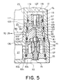
- the embodiment of the present invention is hereinafter explained in view of Figs. 5 and 6.
- the compressor according to the embodiment of the present invention has the similar construction as that of the conventional compressor except for the displacement control valve mechanism. Hence, the explanation of the compressor is omitted and only the displacement control valve mechanism is explained.
- the displacement control valve mechanism 93 includes a casing body 95 and a lid member 55.
- a valve chamber 97 is formed in one end of the casing body 95.
- This valve chamber 97 is communicated with a recess 130 formed in the other end of the casing body 95 by way of a through hole 61.
- the valve chamber 97 reaches the side or peripheral surface of the casing body 95 by way of a communicating hole 99.
- a cylindrical or annular hollow portion 101 is formed between the portion of the casing body 95 which surrounds the communicating hole 99 and an accommodating portion 17a of the rear housing 17.
- the cylindrical hollow portion 101 is communicated with the discharge chamber 25 by way of a communication hole 103.
- a first passage is provided which is formed by a communication passage 89, an annular hollow passage 105, through holes 107, 109, the valve chamber 97, the communication hole 99, the cylindrical hollow portion 101 and the communication hole 103.
- a valve body 117 is disposed which is made of a cylindrical member.
- the valve body 117 is comprised of a large diameter portion 113 having a large diameter extremity and an intermediate diameter portion 115 having a diameter smaller than the large diameter portion 113.
- a cylindrical valve guide 119 is disposed in such a manner that it cannot be removed.
- a coil spring 121 is disposed between the valve guide 119 and the large diameter portion 113 and around the intermediate diameter portion 115.
- the coil spring 121 biases the valve body 117 so as to make the valve body 117 close an opening 123 formed in the bottom portion of the recess, namely a valve seat 125.
- the intermediate diameter portion 115 has a portion thereof slidably inserted and disposed in the valve guide 119.
- a pressure chamber 127 is defined between the upper end of the casing body 95 and the inner wall portion of the accommodating portion 17a.
- a plurality of holes are branched off from the opening 123 formed in the bottom portion of the valve chamber 97.
- One hole is communicated with a recess 130 formed in the other end of the casing body 95 as a through hole 61, while other holes define through holes 107, 109 which extend downwardly in an inclined manner in the casing body 95.
- the through holes 107, 109 reach the side surface or the peripheral surface of the casing body 95 and are communicated with the annular hollow portion 105 defined between the side surface of the casing body 95 and the accommodating portion 17a. This annular hollow portion 105 is communicated with the crank chamber 29 by way of the communication passage 89.
- one through hole 107 has a midst portion thereof communicated with the pressure chamber 127 formed on the upper end of the casing body 95 by way of a communication passage 129 which passes through the inside of the casing body 95. Accordingly, the crank chamber 29 and the pressure chamber 127 are always communicated with each other by way of the communication passage 89, the annular hollow portion 105, the through holes 107, 109 and the communication passage 129 which constitute a second passage.
- the valve body 117 is inserted into the valve guide 119 and receives the pressure in the pressure chamber 127 on one end thereof. Accordingly, the pressure in the crank chamber 29 acting on the contact surface between the valve body 117 and the valve seat 125 is acting on the upper end surface of the valve body 117 by the communication passage 129.
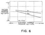
- the above formula (8) expresses the pressure control characteristics of the displacement control valve mechanism according to the embodiment of the present invention.
- the variation of the suction chamber pressure relative to the discharge chamber pressure can be changed by changing the pressure receiving area (Sc) of pressure chamber 127 side of the valve body 117, as shown in Fig. 6.
- the displacement control valve mechanism exhibits the characteristics that in case of Sv > Sc, as the discharge chamber pressure is increased, the suction chamber pressure is decreased, while in case of Sv ⁇ Sc, as the discharge chamber pressure is increased, the suction chamber pressure is increased.
- the present invention can provide the displacement control valve mechanism of the variable displacement compressor which can alter the suction pressure control characteristics by changing the amount of variation of the suction pressure relative to the discharge pressure without changing the seal area of the valve body and the design condition of the bellows side.
- the displacement control valve mechanism according to the present invention can alter the suction pressure control characteristics by an alteration of pressure receiving area Sc of the rod 117. And in practice, this alteration can be easily done by changing the diameter of intermediate diameter portion 115 and the corresponding diameter of the inner wall of the cylindrical valve guide 119.
- the present invention can also provide the variable displacement compressor provided with the displacement control valve mechanism with above-mentioned advantages.
Landscapes
- Engineering & Computer Science (AREA)
- Mechanical Engineering (AREA)
- General Engineering & Computer Science (AREA)
- Compressors, Vaccum Pumps And Other Relevant Systems (AREA)
Applications Claiming Priority (2)
| Application Number | Priority Date | Filing Date | Title |
|---|---|---|---|
| JP16455498 | 1998-06-12 | ||
| JP16455498A JP4051134B2 (ja) | 1998-06-12 | 1998-06-12 | 可変容量圧縮機の容量制御弁機構 |
Publications (2)
| Publication Number | Publication Date |
|---|---|
| EP0964155A2 true EP0964155A2 (fr) | 1999-12-15 |
| EP0964155A3 EP0964155A3 (fr) | 2000-03-01 |
Family
ID=15795377
Family Applications (1)
| Application Number | Title | Priority Date | Filing Date |
|---|---|---|---|
| EP99110771A Withdrawn EP0964155A3 (fr) | 1998-06-12 | 1999-06-04 | Soupape de contrôle de déplacement utilisée dans un compresseur à capacité variable |
Country Status (3)
| Country | Link |
|---|---|
| US (1) | US6179572B1 (fr) |
| EP (1) | EP0964155A3 (fr) |
| JP (1) | JP4051134B2 (fr) |
Cited By (1)
| Publication number | Priority date | Publication date | Assignee | Title |
|---|---|---|---|---|
| CN111749867A (zh) * | 2019-03-28 | 2020-10-09 | 株式会社丰田自动织机 | 容量可变型斜板式压缩机 |
Families Citing this family (17)
| Publication number | Priority date | Publication date | Assignee | Title |
|---|---|---|---|---|
| US7123600B2 (en) * | 1995-06-30 | 2006-10-17 | Interdigital Technology Corporation | Initial power control for spread-spectrum communications |
| JP3479233B2 (ja) | 1999-03-11 | 2003-12-15 | サンデン株式会社 | 可変容量斜板式圧縮機のカム機構 |
| JP3933369B2 (ja) | 2000-04-04 | 2007-06-20 | サンデン株式会社 | ピストン式可変容量圧縮機 |
| FR2809459A1 (fr) | 2000-05-24 | 2001-11-30 | Sanden Corp | Compresseur a cylindree variable du type a came inclinee avec un mecanisme de commande de capacite |
| JP2002147348A (ja) | 2000-11-08 | 2002-05-22 | Sanden Corp | 容量可変型斜板式圧縮機 |
| JP4332294B2 (ja) | 2000-12-18 | 2009-09-16 | サンデン株式会社 | 片頭斜板式圧縮機の製造方法 |
| JP2002221153A (ja) * | 2001-01-23 | 2002-08-09 | Toyota Industries Corp | 容量可変型圧縮機の制御弁 |
| USD465792S1 (en) | 2001-09-18 | 2002-11-19 | Sanden Corporation | Linking member for rotors for swash plate-type compressors |
| USD467943S1 (en) | 2001-09-18 | 2002-12-31 | Sanden Corporation | Linking member for swash plates for swash plate-type compressors |
| JP2003139369A (ja) * | 2001-11-02 | 2003-05-14 | Toyota Industries Corp | 可変容量圧縮機および該可変容量圧縮機を備えた空調装置、可変容量圧縮機における制御方法 |
| JP3982237B2 (ja) * | 2001-11-06 | 2007-09-26 | 株式会社豊田自動織機 | 可変容量圧縮機および該可変容量圧縮機を備えた空調装置、可変容量圧縮機における制御方法 |
| JP4031945B2 (ja) * | 2002-04-09 | 2008-01-09 | サンデン株式会社 | 可変容量圧縮機の容量制御弁 |
| US6939112B2 (en) * | 2002-04-25 | 2005-09-06 | Sanden Corporation | Variable displacement compressors |
| US7320576B2 (en) * | 2002-08-27 | 2008-01-22 | Sanden Corporation | Clutchless variable displacement refrigerant compressor with mechanism for reducing displacement work at increased driven speed during non-operation of refrigerating system including the compressor |
| US6799952B2 (en) * | 2002-09-05 | 2004-10-05 | Delphi Technologies, Inc. | Pneumatically operated compressor capacity control valve with discharge pressure sensor |
| JP2004162567A (ja) * | 2002-11-12 | 2004-06-10 | Fuji Koki Corp | 可変容量型圧縮機用の制御弁 |
| JP6340661B2 (ja) * | 2014-02-27 | 2018-06-13 | 株式会社テージーケー | 可変容量圧縮機用制御弁 |
Citations (1)
| Publication number | Priority date | Publication date | Assignee | Title |
|---|---|---|---|---|
| JPH0474549A (ja) | 1990-07-16 | 1992-03-09 | Iwata Air Compressor Mfg Co Ltd | 2液混合スプレーガン |
Family Cites Families (52)
| Publication number | Priority date | Publication date | Assignee | Title |
|---|---|---|---|---|
| US4037993A (en) | 1976-04-23 | 1977-07-26 | Borg-Warner Corporation | Control system for variable displacement compressor |
| US4425837A (en) | 1981-09-28 | 1984-01-17 | General Motors Corporation | Variable displacement axial piston machine |
| US4480964A (en) | 1982-02-25 | 1984-11-06 | General Motors Corporation | Refrigerant compressor lubrication system |
| JPS60135680A (ja) | 1983-12-23 | 1985-07-19 | Sanden Corp | 揺動式圧縮機 |
| JPS60175783A (ja) | 1984-02-21 | 1985-09-09 | Sanden Corp | 容量可変型斜板式圧縮機 |
| JPH0637874B2 (ja) | 1984-12-28 | 1994-05-18 | 株式会社豊田自動織機製作所 | 可変容量圧縮機 |
| US4685866A (en) | 1985-03-20 | 1987-08-11 | Kabushiki Kaisha Toyoda Jidoshokki Seisakusho | Variable displacement wobble plate type compressor with wobble angle control unit |
| US4688997A (en) | 1985-03-20 | 1987-08-25 | Kabushiki Kaisha Toyoda Jidoshokki Seisakusho | Variable displacement compressor with variable angle wobble plate and wobble angle control unit |
| US4606705A (en) | 1985-08-02 | 1986-08-19 | General Motors Corporation | Variable displacement compressor control valve arrangement |
| JPS6287679A (ja) | 1985-10-11 | 1987-04-22 | Sanden Corp | 容量可変型圧縮機 |
| JPS62206277A (ja) | 1986-03-06 | 1987-09-10 | Toyoda Autom Loom Works Ltd | 揺動斜板型圧縮機におけるワツブルプレ−トの揺動傾斜角戻し機構 |
| JPH0765567B2 (ja) | 1986-04-09 | 1995-07-19 | 株式会社豊田自動織機製作所 | 揺動斜板型圧縮機におけるクランク室圧力の制御機構 |
| JPS62253970A (ja) | 1986-04-25 | 1987-11-05 | Toyota Autom Loom Works Ltd | 可変容量圧縮機 |
| JPS6316177A (ja) | 1986-07-08 | 1988-01-23 | Sanden Corp | 容量可変型圧縮機 |
| JPS6329067A (ja) | 1986-07-21 | 1988-02-06 | Sanden Corp | 連続容量可変型揺動式圧縮機 |
| JPH0217186Y2 (fr) | 1986-07-23 | 1990-05-14 | ||
| JPH037584Y2 (fr) | 1986-08-01 | 1991-02-25 | ||
| JPH0610468B2 (ja) | 1986-08-07 | 1994-02-09 | サンデン株式会社 | 容量可変圧縮機 |
| JPS6341677A (ja) | 1986-08-08 | 1988-02-22 | Sanden Corp | 容量可変圧縮機 |
| JPS6375371A (ja) | 1986-09-16 | 1988-04-05 | Sanden Corp | 容量可変圧縮機 |
| JPS63205474A (ja) | 1987-02-19 | 1988-08-24 | Sanden Corp | 斜板式可変容量圧縮機 |
| JPS63205473A (ja) | 1987-02-19 | 1988-08-24 | Sanden Corp | 斜板式可変容量圧縮機 |
| JPS63205469A (ja) | 1987-02-20 | 1988-08-24 | Sanden Corp | 容量可変型斜板式圧縮機 |
| JPS63149319U (fr) | 1987-03-24 | 1988-09-30 | ||
| JPH0223829Y2 (fr) | 1987-05-19 | 1990-06-28 | ||
| JP2511056B2 (ja) | 1987-07-23 | 1996-06-26 | サンデン株式会社 | 容量可変型斜板式圧縮機 |
| US5168716A (en) | 1987-09-22 | 1992-12-08 | Sanden Corporation | Refrigeration system having a compressor with an internally and externally controlled variable displacement mechanism |
| US5027612A (en) | 1987-09-22 | 1991-07-02 | Sanden Corporation | Refrigerating system having a compressor with an internally and externally controlled variable displacement mechanism |
| US5189886A (en) | 1987-09-22 | 1993-03-02 | Sanden Corporation | Refrigerating system having a compressor with an internally and externally controlled variable displacement mechanism |
| JPS6480776A (en) | 1987-09-22 | 1989-03-27 | Sanden Corp | Volume-variable compressor |
| JPH01142276A (ja) | 1987-11-27 | 1989-06-05 | Sanden Corp | 容量可変型斜板式圧縮機 |
| JPH01182580A (ja) | 1988-01-13 | 1989-07-20 | Sanden Corp | 容量可変型揺動式圧縮機 |
| JPH0447431Y2 (fr) | 1988-04-23 | 1992-11-09 | ||
| JPH02115577A (ja) | 1988-10-24 | 1990-04-27 | Sanden Corp | 容量可変形揺動式圧縮機 |
| JPH0331581A (ja) | 1989-06-28 | 1991-02-12 | Sanden Corp | 容量可変型斜板式圧縮機 |
| JPH0343685A (ja) | 1989-07-05 | 1991-02-25 | Sanden Corp | 容量可変型揺動式圧縮機 |
| JP2892718B2 (ja) | 1989-11-17 | 1999-05-17 | 株式会社日立製作所 | 可変容量形圧縮機 |
| JP2943934B2 (ja) | 1990-03-20 | 1999-08-30 | サンデン株式会社 | 容量可変型斜板式圧縮機 |
| JPH0489873U (fr) | 1990-12-15 | 1992-08-05 | ||
| JPH0599136A (ja) | 1991-10-23 | 1993-04-20 | Sanden Corp | 可変容量型斜板式圧縮機 |
| EP0536989B1 (fr) | 1991-10-07 | 1995-05-03 | Sanden Corporation | Compresseur à plateau en biais avec dispositif à déplacement variable |
| JPH0550083U (ja) | 1991-12-05 | 1993-07-02 | サンデン株式会社 | 容量可変型斜板式圧縮機 |
| JPH05172052A (ja) | 1991-12-18 | 1993-07-09 | Sanden Corp | 可変容量斜板式圧縮機 |
| JP3088536B2 (ja) | 1991-12-26 | 2000-09-18 | サンデン株式会社 | 可変容量型揺動式圧縮機 |
| JPH05312144A (ja) | 1992-05-08 | 1993-11-22 | Sanden Corp | 可変容量斜板式圧縮機 |
| JP3178631B2 (ja) | 1993-01-11 | 2001-06-25 | 株式会社豊田自動織機製作所 | 可変容量型圧縮機用制御弁 |
| JPH06264865A (ja) | 1993-03-12 | 1994-09-20 | Sanden Corp | 容量可変型斜板式圧縮機 |
| JP3355002B2 (ja) | 1993-10-15 | 2002-12-09 | 株式会社豊田自動織機 | 可変容量型圧縮機用制御弁 |
| US5584670A (en) | 1994-04-15 | 1996-12-17 | Kabushiki Kaisha Toyoda Jidoshokki Seisakusho | Piston type variable displacement compressor |
| JP3432994B2 (ja) | 1996-04-01 | 2003-08-04 | 株式会社豊田自動織機 | 可変容量型圧縮機用制御弁 |
| JP3784134B2 (ja) * | 1997-05-14 | 2006-06-07 | 株式会社豊田自動織機 | 制御弁 |
| JPH1182296A (ja) * | 1997-09-05 | 1999-03-26 | Sanden Corp | 可変容量圧縮機 |
-
1998
- 1998-06-12 JP JP16455498A patent/JP4051134B2/ja not_active Expired - Fee Related
-
1999
- 1999-06-03 US US09/324,843 patent/US6179572B1/en not_active Expired - Lifetime
- 1999-06-04 EP EP99110771A patent/EP0964155A3/fr not_active Withdrawn
Patent Citations (1)
| Publication number | Priority date | Publication date | Assignee | Title |
|---|---|---|---|---|
| JPH0474549A (ja) | 1990-07-16 | 1992-03-09 | Iwata Air Compressor Mfg Co Ltd | 2液混合スプレーガン |
Cited By (1)
| Publication number | Priority date | Publication date | Assignee | Title |
|---|---|---|---|---|
| CN111749867A (zh) * | 2019-03-28 | 2020-10-09 | 株式会社丰田自动织机 | 容量可变型斜板式压缩机 |
Also Published As
| Publication number | Publication date |
|---|---|
| JP4051134B2 (ja) | 2008-02-20 |
| EP0964155A3 (fr) | 2000-03-01 |
| US6179572B1 (en) | 2001-01-30 |
| JPH11351140A (ja) | 1999-12-21 |
Similar Documents
| Publication | Publication Date | Title |
|---|---|---|
| US6179572B1 (en) | Displacement control valve mechanism of variable displacement compressor and compressor using such a mechanism | |
| US6485267B1 (en) | Control valve for variable capacity compressors | |
| EP0550228B1 (fr) | Compresseur à plateau en biais à débit variable | |
| US6626645B2 (en) | Control valve for variable capacity compressors | |
| EP1477670B1 (fr) | Dispositif séparateur d'huile pour compresseur à réfrigérant | |
| US6662582B2 (en) | Displacement control valve | |
| US6196808B1 (en) | Variable displacement compressor and displacement control valve system for use therein | |
| EP0809025A1 (fr) | Piston pour compresseur à piston | |
| EP0631050A1 (fr) | Pompe | |
| US7644729B2 (en) | Capacity control valve | |
| US6102668A (en) | Electromagnetic control valve | |
| EP1479908A2 (fr) | Soupape de régulation pour compresseurs à capacité variable | |
| CN102057161A (zh) | 可变容量压缩机 | |
| EP0318316A1 (fr) | Compresseur à plateau en biais avec mécanisme à déplacement variable | |
| DE19821499A1 (de) | Elektromagnetisches Ventil | |
| EP1512871A1 (fr) | Soupape de contrôle pour un compresseur à capacité variable | |
| US7077380B2 (en) | Capacity control drive | |
| AU646336B2 (en) | Slant plate type compressor with variable displacement mechanism | |
| EP1489304A1 (fr) | Appareil de contrôle pour contrôler le déplacement d'un compresseur à déplacement variable | |
| EP0900937A2 (fr) | Appareil et méthode pour la commande d'un appareil de déplacement de fluide avec mécanisme à déplacement variable | |
| JPWO2019142931A1 (ja) | 容量制御弁 | |
| CN1237694A (zh) | 变排量致冷压缩机及其装配方法 | |
| US6688853B1 (en) | Control valve for regulating flow between two chambers relative to another chamber | |
| EP0260667B1 (fr) | Compresseur à plateau en biais avec mécanisme à déplacement variable | |
| US20060039798A1 (en) | Control valve for variable displacement compressor |
Legal Events
| Date | Code | Title | Description |
|---|---|---|---|
| PUAI | Public reference made under article 153(3) epc to a published international application that has entered the european phase |
Free format text: ORIGINAL CODE: 0009012 |
|
| AK | Designated contracting states |
Kind code of ref document: A2 Designated state(s): AT BE CH CY DE DK ES FI FR GB GR IE IT LI LU MC NL PT SE |
|
| AX | Request for extension of the european patent |
Free format text: AL;LT;LV;MK;RO;SI |
|
| PUAL | Search report despatched |
Free format text: ORIGINAL CODE: 0009013 |
|
| AK | Designated contracting states |
Kind code of ref document: A3 Designated state(s): AT BE CH CY DE DK ES FI FR GB GR IE IT LI LU MC NL PT SE |
|
| AX | Request for extension of the european patent |
Free format text: AL;LT;LV;MK;RO;SI |
|
| AKX | Designation fees paid | ||
| STAA | Information on the status of an ep patent application or granted ep patent |
Free format text: STATUS: THE APPLICATION IS DEEMED TO BE WITHDRAWN |
|
| 18D | Application deemed to be withdrawn |
Effective date: 20000902 |
|
| REG | Reference to a national code |
Ref country code: DE Ref legal event code: 8566 |