EP1710657A2 - Kippvorrichtung und elektronische Vorrichtung - Google Patents
Kippvorrichtung und elektronische Vorrichtung Download PDFInfo
- Publication number
- EP1710657A2 EP1710657A2 EP06006767A EP06006767A EP1710657A2 EP 1710657 A2 EP1710657 A2 EP 1710657A2 EP 06006767 A EP06006767 A EP 06006767A EP 06006767 A EP06006767 A EP 06006767A EP 1710657 A2 EP1710657 A2 EP 1710657A2
- Authority
- EP
- European Patent Office
- Prior art keywords
- section
- moving body
- guide
- tilting
- display
- Prior art date
- Legal status (The legal status is an assumption and is not a legal conclusion. Google has not performed a legal analysis and makes no representation as to the accuracy of the status listed.)
- Granted
Links
Images


Classifications
-
- G—PHYSICS
- G06—COMPUTING OR CALCULATING; COUNTING
- G06F—ELECTRIC DIGITAL DATA PROCESSING
- G06F1/00—Details not covered by groups G06F3/00 - G06F13/00 and G06F21/00
- G06F1/16—Constructional details or arrangements
- G06F1/1601—Constructional details related to the housing of computer displays, e.g. of CRT monitors, of flat displays
-
- G—PHYSICS
- G11—INFORMATION STORAGE
- G11B—INFORMATION STORAGE BASED ON RELATIVE MOVEMENT BETWEEN RECORD CARRIER AND TRANSDUCER
- G11B33/00—Constructional parts, details or accessories not provided for in the other groups of this subclass
- G11B33/02—Cabinets; Cases; Stands; Disposition of apparatus therein or thereon
-
- B—PERFORMING OPERATIONS; TRANSPORTING
- B60—VEHICLES IN GENERAL
- B60R—VEHICLES, VEHICLE FITTINGS, OR VEHICLE PARTS, NOT OTHERWISE PROVIDED FOR
- B60R11/00—Arrangements for holding or mounting articles, not otherwise provided for
- B60R11/02—Arrangements for holding or mounting articles, not otherwise provided for for radio sets, television sets, telephones, or the like; Arrangement of controls thereof
-
- F—MECHANICAL ENGINEERING; LIGHTING; HEATING; WEAPONS; BLASTING
- F16—ENGINEERING ELEMENTS AND UNITS; GENERAL MEASURES FOR PRODUCING AND MAINTAINING EFFECTIVE FUNCTIONING OF MACHINES OR INSTALLATIONS; THERMAL INSULATION IN GENERAL
- F16D—COUPLINGS FOR TRANSMITTING ROTATION; CLUTCHES; BRAKES
- F16D63/00—Brakes not otherwise provided for; Brakes combining more than one of the types of groups F16D49/00 - F16D61/00
-
- G—PHYSICS
- G11—INFORMATION STORAGE
- G11B—INFORMATION STORAGE BASED ON RELATIVE MOVEMENT BETWEEN RECORD CARRIER AND TRANSDUCER
- G11B33/00—Constructional parts, details or accessories not provided for in the other groups of this subclass
- G11B33/10—Indicating arrangements; Warning arrangements
-
- H—ELECTRICITY
- H04—ELECTRIC COMMUNICATION TECHNIQUE
- H04N—PICTORIAL COMMUNICATION, e.g. TELEVISION
- H04N5/00—Details of television systems
- H04N5/64—Constructional details of receivers, e.g. cabinets or dust covers
-
- B—PERFORMING OPERATIONS; TRANSPORTING
- B60—VEHICLES IN GENERAL
- B60R—VEHICLES, VEHICLE FITTINGS, OR VEHICLE PARTS, NOT OTHERWISE PROVIDED FOR
- B60R11/00—Arrangements for holding or mounting articles, not otherwise provided for
- B60R2011/0042—Arrangements for holding or mounting articles, not otherwise provided for characterised by mounting means
- B60R2011/008—Adjustable or movable supports
- B60R2011/0082—Adjustable or movable supports collapsible, e.g. for storing after use
-
- B—PERFORMING OPERATIONS; TRANSPORTING
- B60—VEHICLES IN GENERAL
- B60R—VEHICLES, VEHICLE FITTINGS, OR VEHICLE PARTS, NOT OTHERWISE PROVIDED FOR
- B60R11/00—Arrangements for holding or mounting articles, not otherwise provided for
- B60R2011/0042—Arrangements for holding or mounting articles, not otherwise provided for characterised by mounting means
- B60R2011/008—Adjustable or movable supports
- B60R2011/0085—Adjustable or movable supports with adjustment by rotation in their operational position
- B60R2011/0087—Adjustable or movable supports with adjustment by rotation in their operational position around two axes
-
- B—PERFORMING OPERATIONS; TRANSPORTING
- B60—VEHICLES IN GENERAL
- B60R—VEHICLES, VEHICLE FITTINGS, OR VEHICLE PARTS, NOT OTHERWISE PROVIDED FOR
- B60R11/00—Arrangements for holding or mounting articles, not otherwise provided for
- B60R2011/0042—Arrangements for holding or mounting articles, not otherwise provided for characterised by mounting means
- B60R2011/008—Adjustable or movable supports
- B60R2011/0092—Adjustable or movable supports with motorization
-
- B—PERFORMING OPERATIONS; TRANSPORTING
- B60—VEHICLES IN GENERAL
- B60R—VEHICLES, VEHICLE FITTINGS, OR VEHICLE PARTS, NOT OTHERWISE PROVIDED FOR
- B60R11/00—Arrangements for holding or mounting articles, not otherwise provided for
- B60R2011/0094—Arrangements for holding or mounting articles, not otherwise provided for characterised by means for covering after user, e.g. boxes, shutters or the like
Definitions
- the present invention relates to a tilting apparatus that makes a moving section, for example a display section and an operation section, provided in an electronic apparatus body perform a tilting operation, and relates to an electronic apparatus equipped with the tilting apparatus.
- rotation includes angular displacement of less than 360 degrees, or rotation of 360 degrees or more.
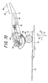
- FIG. 90 is a cross sectional view of an electronic apparatus drive mechanism 301 of the first conventional technology.
- the electronic apparatus drive mechanism 301 serves as a tilting mechanism, in which a pair of support members 302 is coupled to an end portion of an electronic apparatus 303.
- drive unit 304 reciprocating the pair of support members 302, the electronic apparatus 303 in a predetermined position can move at a slant in one direction.
- JP-A 10-51712 (1998 ) pages 4 to 6, and FIG. 1).
- the electronic apparatus 303 is configured to movable at a slant in one direction. Through such slant movement of the electronic apparatus 303, the electronic apparatus 303 is increased in functionality. In such an electronic apparatus drive mechanism 301, however, the electronic apparatus 303 can move at a slant only in one direction, and the inclinable range is thus small. With the small inclinable range, the electronic apparatus 303 may not fulfill its functionality as expected. Exemplified here is a case of applying the electronic apparatus drive mechanism 301 to a tilting mechanism of an on-vehicle display.
- the electronic apparatus drive mechanism 301 is disposed at an angle with some tilt upward in the front.
- the electronic apparatus 303 problematically reflects sun's rays, and displays thereon reflections of landscape, e.g., sky. Even if the electronic apparatus 303 is further made to move at a slant for betterment, it only aggravates such reflection problem in most cases, and the viewability of the electronic apparatus 303 is reduced for images to be displayed thereon.
- the electronic apparatus drive mechanism 301 is equipped with a reproduction device for reproduction of recording media, e.g., compact disks (CDs) or digital versatile discs (DVDs).
- a reproduction device for reproduction of recording media
- CDs compact disks
- DVDs digital versatile discs
- the electronic apparatus 303 is made to move at a slant to expose a recording medium insertion/removal port, which is not shown, of the reproduction device.
- making the electronic apparatus 303 move at a slant only in one direction will block the user's view depending on his or her eye point.
- This resultantly makes difficult for the user to see where the insertion/removal port is.
- the user finds it thus difficult to insert or remove the recording medium, in other words, the operability of other electronic apparatus is reduced.
- the electronic apparatus 303 being tiltable only in one direction from its predetermined position cannot satisfy the functionality as intended.
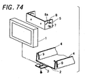
- FIG. 74 is an exploded perspective view of a vehicle-mounted display device of a second conventional technology.
- the vehicle-mounted display device of the second conventional technology is configured by a chassis 2, a support plate 3 that supports a display section 1 from below, side frames 4 provided to right and left of the chassis 2, and a holding plate 5 for use for keeping hold of the display section 1 with respect to the side frames 4 at a predetermined angle.
- the support plate 3 is provided on the chassis 2 so as to be freely displaced thereagainst at its end, and the side frames 4 are each formed with a fitting slot 9 extending in the vertical direction.
- the holding plate 5 is provided with sliding surfaces that slide in contact with the side frames 4, and the sliding surfaces are each formed with a plurality of attachment holes 8a on its upper portion at regular intervals.
- the sliding surfaces are each also formed with, on its lower portions, first and second pins 7 and 8 that extend outward to engage with the corresponding fitting slot 9.
- the second pin 8 is so provided as to be attachable/detachable to/from any of the attachment holes 8a.
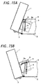
- FIGS. 75A and 75B are each a side view showing a tilted display section 1 of a vehicle-mounted display device.
- the display section 1 can be made to perform a tilting operation.
- the display section 1 can be made to perform the tilting operation upward when the second pin 8 is attached to the attachment hole 8a in a close range of the display section 1.
- the display section 1 can be made to perform the tilting operation downward when the second pin 8 is attached to the attachment hole 8a at some space from the display section 1.
- JP-A 2002-154382 refer to Japanese Unexamined Patent Publication JP-A 2002-154382 .
- a display device is configured to be tiltable against the apparatus body.
- the display device is provided with hinge sections each at its upper and lower portions for tilting operation.
- To make the display device perform an upward tilting operation the lower portion of the display device is detached from the lower hinge section, and the display device is angularly displaced against the upper hinge section.
- To make the display device perform a downward tilting operation the upper portion of the display device is detached from the upper hinge section, and the display device is angularly displaced against the lower hinge section.
- the display device can perform both upward and downward tile operations.
- the problem with the second conventional technology is that, to make the display section perform the tilting operation, there needs to annoyingly change the position of the second pin 8 for every tilting operation. What is more, when the second pin 8 is removed from the attachment hole 8a to make the display section perform the tilting operation, there is a possibility of making the display section unstable so that the display section may perform the tile operation even if not desired.
- the problem with the third conventional technology is that, when the display device is made to perform the tilting operation, the two hinge sections may be damaged as being detachable. Moreover, because the display device is electrically controlled by the apparatus body, with the hinge portions being detachable, the configuration becomes complicated to establish an electrical connection between the display device and the apparatus body.
- an object of the invention is to provide a tilting apparatus capable of making a moving section perform a tilting operation with stability or execute a desired function, and provide an electronic apparatus equipped with the tilting apparatus.
- the invention provides a tilting apparatus comprising:
- one side of the moving body can be displaced to incline the moving body.
- the second drive section By driving the second drive section, the other side of the moving body can be displaced to incline the moving body.
- the moving body can be displaced at both sides separately by each corresponding drive section so that the moving body can be made to perform the tile operation by the drive sections with stability.
- a range of inclinable angles for the moving body can be increased, so that the moving body can be disposed at any desired position. Inclination angle can be optimum in consideration of the requirements for the moving body, e.g., placement or surroundings.
- the tilting apparatus further comprises a moving body support section for supporting the moving body at both side portions on one side thereof so that the moving body can be angularly displaced, wherein a first drive section inclines the moving body by displacing one side of the moving body support section, and/or a second drive section angularly displaces the moving body by moving the other side of the moving body away from the other side of the moving body support section.
- one side of the moving body support section can be displaced to incline the moving body.
- the other side of the moving body is brought away from the other side of the moving body support section to angularly displace the moving body.
- the moving body can be angularly displaced at both sides separately by each corresponding drive section. Accordingly, it is possible to realize a configuration in which the moving body can be made to perform the tilting operation by the drive sections with stability.
- the first drive section includes a first tilting mechanism section that performs a first tilting operation to displace one side of the moving body from a reference position
- the second drive section includes a second tilting mechanism section that performs a second tilting operation to displace another side of the moving body from the reference position
- the first tilting mechanism section enables the moving body to go through the first tilting operation from the reference position
- the second tilting mechanism section enables the moving body to go through the second tilting operation from the reference position.
- the first and/or second tilting operations can be put into action by each corresponding mechanism body.
- the first and/or second tilting operations both displace the moving body from the reference position, thereby preventing the moving body from making any extra movement other than the first and/or second tilting operations.
- the moving body makes no displacement unless it is desired during the first and/or second tilting operations, e.g., the moving body juts from the electronic equipment body, thereby favorably leading to the operation with stability.
- the moving body can be thus disposed with ease at any user desired position, and is not unnecessarily displaced from any desired position once positioned.
- the moving body is provided with a plurality of engagement sections
- the first drive section and/or the second drive section include a support body having a to-be-engaged section for slidably supporting the engagement sections.
- the moving body is provided with a plurality of engagement sections.
- On the support body is formed a to-be-engaged section for slidably supporting the plurality of engagement sections.
- the engagement sections are supported by the to-be-engaged section of the support body before being slid.
- a plurality of engagement sections are supported by the support body, and/or the engagement sections can slide the support body, thereby allowing the moving body to slide.
- the moving body can be driven to move at a slant in one and/or the other directions by each of the drive sections while being supported by the support body.
- the tilting apparatus includes, when the other side of the moving body moves away from the other side of the moving body support section, a cover member that covers an area between the other side of the moving body and the other side of the moving body support section.
- a cover member is provided to cover an area between the other side of the moving body and the other side of the moving body support section when the other side of the moving body moves away from the other side of the moving body support section. This prevents any unwanted dust or foreign substances from entering the area between the moving body and the moving body support section. Accordingly, the tilting apparatus and/or the electronic apparatus equipped with the tilting apparatus will not suffer from any problem caused by such foreign substances, thereby easing maintenance.
- the second tilting mechanism section angularly displaces the moving body with one side thereof serving as a fulcrum.
- the second tilting mechanism section angularly displaces the moving body with one side thereof serving as a fulcrum, thereby preventing the moving body from making any extra movement other than the first and/or second tilting operations.
- the moving body thus makes no displacement unless it is desired, thereby favorably leading to the operation with stability.
- the first tilting mechanism section in response to a command asking for the second tilting operation in a state where the moving body is inclined by driving of the first tilting mechanism section, the first tilting mechanism section is driven to put the moving body back to the reference position and then, the second tilting mechanism section is driven to perform the second tilting operation, and in response to a command asking for the first tilting operation in a state where the display body is inclined by driving of the second tilting mechanism section, the second tilting mechanism section is driven to put the moving body back to the reference position and then, the first tilting mechanism section is driven to perform the first tilting operation.
- the corresponding tilting mechanism section is driven after the moving body is put back to the reference position by driving the tilting mechanism section.
- the first and/or second tilting operations are always started at the reference position serving as an operation start position, thereby preventing the unnecessary displacement of the moving body. This enables to dispose the moving body at any desired position, i.e., for the user, any place wherever easy to see and operate the moving body.
- the first and/or second tilting operation can be put into action in a row with the reference position of the moving body as a wrap-around position.
- the moving body thus can be smoothly operated to be disposed at any desired position.
- the tilting apparatus further comprises a common drive source for driving both the first and/or second tilting mechanism bodies; and a switch section for switching back and forth between the first and second tilting mechanism bodies, either of which is to be connected to the drive source, in a state where the moving body is positioned at the reference position.
- a drive source is provided to forward a drive force to both the first and/or second tilting mechanism bodies, and with the moving body positioned at the reference position, a switch section switches back and forth between the first and/or second tilting mechanism bodies, either of which is to be connected to the drive source.
- the plurality of engagement sections comprises a pair of first engagement sections provided on both side portions of one side of the moving body, and/or a pair of second engagement sections provided on both side portion of another side of the moving body, and the support body includes:
- the plurality of the engagement sections includes the first engagement section and the second engagement section.
- the support body includes the first and/or second support members.
- the first support member has the guide mechanism
- the second support member has the first member and/or second member which have the to-be-engaged sections.
- the first member has the to-be-engaged section to be engaged with the first engagement section while the second member has the to-be-engaged section to be engaged with the second engagement section.
- the second support member can be supported by a plurality of engagement sections without fail.
- the moving body is guided by the guide mechanism so as to be driven to move at a slant in a state where the plurality of the engagement sections is supported by the to-be-engagement section of the second support members.
- the invention provides a tilting apparatus comprising:
- the tilting apparatus can angularly displaceably support the moving body by the moving body support section. This makes it possible to make the moving body perform the tilting operation.
- the tilting apparatus is displaced with respect to the moving body support section, by including a cover member to cover an area between the other side of the moving body and the other side of the moving body support section, the area between the moving body and the moving body support section can be protected from any unwanted dust or foreign substances. Accordingly, the tilting apparatus and/or the electronic apparatus equipped with the tilting apparatus will suffer from any problem caused by such foreign substances, thereby easing maintenance.
- the invention provides a method for tilting a moving body, comprising:
- the moving body is made to perform the first and/or second tilting operations, from the reference position, thereby preventing the moving body from making any extra movement other than the first and/or second tilting operations.
- the moving body thus makes no displacement unless it is desired, thereby favorably leading to the operation with stability.
- the moving body can be thus disposed with ease at any user's desired position, and is not unnecessarily displaced from the desired position once positioned.
- an electronic apparatus comprising:
- the electronic apparatus is provided with first and/or second drive sections that displace the one side and/or the other side of the moving body so that the moving body is inclined. Since each of the drive sections is provided on the electronic apparatus body, it is possible to realize the electronic apparatus that can be favorably made to perform the tilting operation.
- the above mentioned features may be combined in any way, partly or as a whole.
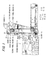
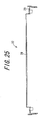
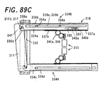
- FIG. 1 is a schematic partially-enlarged left side view of a tilting apparatus 10 according to the first embodiment of the invention.
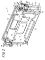
- FIG. 2 is a perspective view of a first chassis 11 configuring the tilting apparatus 10 being in a second tilting operation
- FIG. 3 is a right side view of the first chassis 11 being in the second tilting operation.
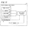
- the tilting apparatus 10 is provided on a vehicle-mounted audio device 12 serving as electronic apparatus, for example, and makes a moving section of the vehicle-mounted audio device 12 perform the tilting operation.
- the moving section is embodied by a display body, and specifically, by a panel display 13 provided on one surface portion of the vehicle-mounted audio device 12, and a first panel holder 21 that keeps hold of the panel display 13.
- components are so configured as to perform a first tilting operation, through mechanical driving.
- the components include: the panel display 13, the first panel holder 21, and a second panel holder 22.
- the panel display 13 is provided on one surface portion of a device body 14 of the vehicle-mounted audio device 12. The surface portion is the one on the predetermined front side of X1.
- the first panel holder 21 keeps hold of the panel display 13, and the second panel holder 22 keeps hold of the first panel holder 21.
- the panel display 13, and the first panel holder 21 keeping hold of the panel display 13 are so configured as to perform a second tilting operation, also through mechanical driving.
- the first tilting operation is equivalent in meaning to the operation of angular displacement of the components from their reference positions along the surface portion in such a manner that one side portions of the components come closer to the front X1 side than their other portions.
- the components here include the panel display 13, the first panel holder 21 keeping hold of the panel display 13, and the second panel holder 22 keeping hold of the first panel holder 21.
- the panel display 13 being at the reference position is inclined by directing, toward the front X1 side, one side of the respective components, i.e., the panel display 13, the first panel holder 21, and the second panel holder 22.
- the second tilting operation is equivalent in meaning to the operation of angular displacement of the components from their reference positions in such a manner that the other side portions of the components come closer to the front X1 side than their one portions.
- the components here include the panel display 13, and the first panel holder 21 keeping hold of the panel display 13.
- the panel display 13 being at the reference position, and the first panel holder 21 keeping hold of the panel display 13 are inclined by directing, toward the front X1 side, the other side of the respective components, i.e., the panel display 13 and the first panel holder 21.
- the tilting apparatus 10 is configured to include a first chassis 11, and a second chassis 15.
- the first chassis 11 supports the panel display 13.
- the second chassis 15 moves in concert with the first chassis 11, and puts the components into action, i.e., the first and second tilting operations. That is, the components for the first tilting operation include the panel display 13, the first panel holder 21 keeping hold of the panel display 13, and the second panel holder 22 supporting the first panel holder 21.
- the components for the second tilting operation include the panel display 13, and the first panel holder 21 keeping hold of the panel display 13.
- a push lever 16 configuring the second chassis 15 slides in a predetermined thrust direction P1, and thrusts a thrust section 17 of the first panel holder 21 configuring the first chassis 11.
- the first panel holder 21 of the first chassis 11 goes though the second tilting operation from a reference position indicated by the solid line of FIG. 1 (refer also to FIGS. 2 and 3).
- the angular displacement is thus made so that the surface portion of the first panel holder 21 of the first chassis 11 is directed downward against the front X1 side.
- a slider 18 configuring the second chassis 15 slides toward the front X1
- the lower side portion of the first chassis 11 is responsively made to slide also toward the front side X1.
- the first tilting operation is put into action as indicated by virtual lines, and the angular displacement is thus made so that the surface portion of the first chassis 11 is angularly displaced upward against the front X1 side.
- the first chassis 11 is so configured as to stop its movement during the second tilting operation at a predetermined position.
- the predetermined position is positioned at the lower end portion of the first panel holder 21, with an angle of 15 degrees in one rotation direction about a rotation axis line.
- the predetermined position is located at the position with an angle of 10 degrees, and in FIG. 3C, with an angle of 5 degrees.
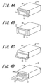
- FIGS. 4A to 4D are all a schematic perspective view of the vehicle-mounted audio device 12.
- FIGS. 5A to 5D are all a schematic left side view of the vehicle-mounted audio device 12.
- a device body 14 of substantially a rectangular parallelepiped is securely fixed to the vehicle at a predetermined position.
- the first panel holder 21 of the first chassis 11 performs the first tilting operation against the device body 14, and the first chassis 11 performs the second tilting operation against the device body 14.
- the device body 14 is of substantially a rectangular parallelepiped, extending toward a predetermined reference axis line thereof (hereinafter, sometimes referred to as "body axis line").
- the device body 14 is provided with the first chassis 11 configuring a part of the tilting apparatus 10 on one surface portion in one direction of the body axis line.
- the first chassis 11 is almost a plate, and at the reference position, the thickness direction thereof is almost parallel to the direction of the body axis line.
- the first chassis 11 is provided with the panel display 13 as one piece on the surface portion of the chassis 11 in one thickness direction. With this configuration, the first chassis 11 supports the panel display 13, and when the first chassis 11 moves, the panel display 13 also moves as one piece.
- the direction along which the body axis line thereof extends sometimes referred to as thickness direction.
- directions vertical to the thickness direction of the first chassis 11 if with a projection plane vertical to the body axis line, the direction extending along the longer side of the surface in the thickness direction is sometimes referred to as length direction.
- the direction vertical to both the thickness and length directions of the first chassis 11 is sometimes referred to as width direction.
- the direction along which the body axis line is extending is sometimes referred to as fore-and-aft direction X.
- directions vertical to the fore-and-aft direction if with a projection plane vertical to the body axis line, the direction extending along the longer side of the surface along the body axis line is sometimes referred to as lateral direction Y.
- the direction vertical to both the fore-and-aft and lateral directions of the first chassis 11 is sometimes referred to as vertical direction Z.
- the first chassis 11 performs the first tilting operation, from the reference position at which the fore-and-aft direction of the device body 14 is substantially parallel to the thickness direction of the first chassis 11.
- the front surface of the first chassis 11, i.e., one surface in the thickness direction is angularly displaced as if being directed upward of the device body 14, i.e., one vertical direction.
- the first chassis 11 is so configured as to be angularly displaced as far as the thickness direction thereof becomes substantially parallel to the vertical direction of the device body 14.
- one surface portion of the device body 14 on the front X1 side is opened toward the outside.
- On one surface of the device body 14 on the front X1 side is formed with an insertion portion 14a to accept therein various types of recording medium.
- a user inserts a medium into this insertion portion 14a to provide the vehicle-mounted audio device 12 with various types of information, e.g., music information or map information, so that the user can use the vehicle-mounted audio device 12 in a suitable manner.
- the first chassis 11 When the first chassis 11 performs the second tilting operation, from the reference position of FIGS. 4B and 5B, as shown in FIGS. 4A and 5A, the first chassis 11 is angularly displaced so that a front surface thereof is directed to the lower portion of the vehicle-mounted device body 14, i.e., the other vehicle direction.
- a cover 19 (will be described later) provided to the first chassis 11 covers the area between the device body 14 and the first chassis 11 so as not to allow entrance of any foreign substance as dust.
- the tilting apparatus 10 is configured to include the first chassis 11, the second chassis 15, and a drive mechanism body 20 (refer to FIG. 34) that drives the first and second chassis 11 and 15.
- the first chassis 11 will be described first, and then the descriptions of the second chassis 15 and the drive mechanism body 20 will follow.
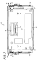
- FIG. 6 is a perspective view of the first chassis 11 viewed from the rear.
- FIG. 7 is a front view of the first chassis 11, and
- FIG. 8 is a right side view of the first chassis 11.
- FIG. 9 is a rear side view of the first chassis 11, and
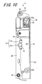
- FIG. 10 is a left side view of the first chassis 11.
- FIG. 11 is a bottom view of the first chassis 11, and
- FIG. 12 is a plane view of the first chassis 11.
- the first chassis 11 is configured to include the first panel holder 21, the second panel holder 22, the cover 19, cover guides 23, and second tilt reset springs 24.
- the first panel holder 21 keeps hold of the panel display 13, and the second panel holder 22 supports the first panel holder 21 at one side portion to allow angular displacement.
- the cover 19 covers the area between the first and second panel holders 21 and 22, and the cover guide 23 guides a cover guide pin 38 provided to the cover 19.
- the second tilt reset spring 24 provides a spring force to the first panel holder 21.
- the second tilt reset spring 24 one end portion is coupled to the first panel holder 21, and the other end portion is coupled to the second panel holder 22.
- the second tilt reset spring 24 provides the second panel holder 22 with a spring force in a second direction in which the first panel holder is located relatively close. As such, when the first chassis 11 is in a stationary state with no external force acting thereon, the first panel holder 21 is brought to the closed position along the second panel holder 22 by the spring force of the second tilt reset spring 24. The closed position is along the second panel holder 22.
- the first panel holder 21 can be angularly displaced between a closed position of FIG. 6, i.e., disposed along the second panel holder 22, and an open position of FIG. 2, i.e., disposed with some space away from the second panel holder 22.
- the first panel holder 21 When the first panel holder 21 is at the open position, around the rotation axis line of the first and second panel holders 21 and 22 at their one corresponding side portions, the other side portion of the first panel holder 21 is displaced in a direction away from the other side portion of the second panel holder 22, and the first panel holder 21 is angularly displaced against the second panel holder 22.
- the cover 19 covers an area between the first and second panel holders 21 and 22 on the other side of the width direction, i.e., the other side of the panel display 13. More in detail, when the first panel holder 21 is at the closed position, the cover 19 is disposed and housed along one surface portion of the second panel holder 22 (refer to FIG. 6). When the first panel holder 21 is at the open position, the cover 19 is pulled out on the other side of the first panel holder 21 as if covering the area between the first and second panel holders 21 and 22. The cover 19 is pulled out or housed in response to when the first panel holder 21 is angularly displaced (refer to FIGS. 2 and 3).
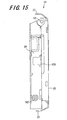
- FIG. 13 is a perspective view of the first panel holder 21 viewed from the rear
- FIG. 14 is a front view of the first panel holder 21
- FIG. 15 is a right side view of the first panel holder 21
- FIG. 16 is a rear side view of the first panel holder 21
- FIG. 17 is a left side view of the first panel holder 21
- FIG. 18 is a plane view of the first panel holder 21
- FIG. 19 is a bottom view of the first panel holder 21.
- the first panel holder 21 is almost a frame, and the projected form on a plane vertical to the thickness direction is substantially rectangular.
- the first panel holder 21 is configured to include a first panel bottom section 25, first panel short-side wall sections 26, and first panel long-side wall sections 27.
- the first panel bottom section 25 is provided to be substantially parallel to a virtual plane including short-and long-side directions. When viewed from the thickness direction, the short-side extends in the short-side direction, and the long-side extends in the long-side direction.
- the first panel short-side wall sections 26 are coupled to each corresponding end portion of the first panel bottom section 25 in the long-side direction, and extend in one thickness direction.
- the first panel long-side wall sections 27 are coupled to each corresponding end portion of the first panel bottom section 25 in the short-side direction, and extend in one thickness direction.
- the first panel holder 21 is supported with respect to the second panel holder 22 to be able to be angularly displaced with first engagement members 103 serving as fulcrums. Such supporting is achieved by first engagement sections 102 being engaged with the first engagement members 103 provided to the second panel holder 22.
- the first engagement sections 102 are provided at both end portions in the long-side direction of the first panel holder 21, i.e., one side of the short-side direction.
- Second engagement sections 101 and the cover member 19 are engaged with one another by the second engagement members 104.
- the second engagement sections 101 are provided at both end portions in the long-side direction, i.e., the other side of the short-side direction.
- first panel holder 21 to be angularly displaced around the rotation axis line extending in the long-side direction, i.e., one side of the short-direction. Through such angular displacement, the other side of the short-side direction can come closer or move away from the second panel holder 22.
- the thrust sections 17 are attached to thrust section attachment holes 100 provided each to the first panel short-side wall section 26, i.e., at the external portion in the long-side direction, and in the vicinity of the center of the first panel holder 21 in the short-side direction.
- the thrust sections 17 are thrusted by the sliding displacement of the push lever 16 (refer to FIG. 1) configuring the second chassis 15.
- the thrust sections 17 are each provided with a protruding portion 17a that protrudes in the other thickness direction, and a guide portion 17b that guides the second panel holder 22 (refer to FIG. 6).
- the thrust sections 17 are made of a material of low friction resistance, e.g., synthetic resin, so that any noise can be suppressed during the second tilting operation.
- at least the protruding portions 17a and the guide portions 17b may be coated with a coating material or by a solid lubrication film that possibly reduces the friction resistance. With this being the case, the similar effects as the present embodiment can be achieved.
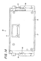
- FIG. 20 is a perspective view of the second panel holder 22 viewed from the rear
- FIG. 21 is a front view of the second panel holder 22
- FIG. 22 is a rear side view of the second panel holder 22
- FIG. 23 is a right side view of the second panel holder 22
- FIG. 24 is a left side view of the second panel holder 22
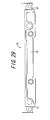
- FIG. 25 is a plane view of the second panel holder 22
- FIG. 26 is a bottom view of the second panel holder 22.
- the second panel holder 22 is almost a plate, and the projected form on a virtual plane vertical to the thickness direction is substantially rectangular, and the projected form on a virtual plane parallel to both the thickness and longitudinal directions is substantially U-shaped.
- the second panel holder 22 is configured to include a second panel bottom section 28, and second panel short-side wall sections 29.
- the second panel bottom section 28 is provided to be substantially parallel to a virtual plane including short- and long-side directions. When viewed from the thickness direction, the short-side extends in the short-side direction, and the long-side extends in the long-side direction.
- the second panel short-side wall sections 29 are coupled to each corresponding end portion of the second panel bottom section 28 in the long-side direction, and extend in one thickness direction.
- the first panel holder 21 is supported with respect to the second panel holder 22 to be able to be angularly displaced with the first engagement members 103 serving as fulcrums.
- Such supporting is achieved by the first engagement member 103 being attached to third engagement sections 105 provided to the second panel holder 22.
- the third engagement sections 105 are provided at both end portions in the long-side direction of the second panel holder 22, i.e., one side of the short-side direction.
- the first engagement members 103 are engaged with the first engagement section 102 of the first panel holder 21.
- This thus allows the second panel holder 22 to be angularly displaced around the rotation axis line extending in the long-side direction, i.e., one side of the short-direction. Through such angular displacement, the other side of the short-side direction can come closer or move away from the first panel holder 21.
- the dimension of the second panel holder 22 in the short-side direction is formed smaller than the dimension of the first panel holder 21 in the short-side direction.
- a cover housing space 30 is formed on the other side of the second panel holder 22 in the short-side direction for housing of the cover 19.
- the cover 19 is housed in the cover housing space 30 along the second panel holder 22, mainly along the second panel bottom section 28.
- the protruding portion 17a of the thrust section 17 is defined by dimension in such a manner that the protruding portion 17a protrudes in the other thickness direction of the second panel holder 22.
- the second panel short-side wall sections 29 are each formed with a first attachment section 106, to which a first chassis guide pin 32 is attached, on each corresponding end portion in the long-side direction, i.e., the other side of the short-side direction.
- the first chassis guide pin 32 protrudes toward the outside in the long-side direction.
- the first chassis guide pin 32 is so configured as to be inserted into a first chassis guide slot 33 provided to the device body 14.
- the first chassis guide slot 33 extends in the vertical direction of the device body 14, and the first chassis guide pin 32 is guided to freely slide along the first chassis guide slot 33.
- the second panel short-side wall sections 29 are also formed with a second attachment section 107, to which a slider guide pin 34 is attached, on each corresponding end portion in the long-side direction, i.e., one side of the short-side direction.
- Slider guide pin 34 is supported at the tip portion of the slider 18 configuring the second chassis 15 (refer to FIG. 1) to be angularly displaced.
- the second panel short-side wall sections 29 are also each formed with a third attachment section 108, to which a first panel guide pin 35 is attached.
- the first panel guide pin 35 protrudes inwardly in the long-side direction, being in the vicinity of the center in the short-side direction.
- the second panel short-side wall sections 29 are also each formed with a fourth attachment section 109, to which the cover guide 23 is attached on each corresponding end portion in the long-side direction, i.e., on the other side of the short-side direction.
- the fourth attachment section 109 is formed with a slot 23b going through in the long-side direction, and into which the cover guide pin 38 provided to the cover 19 can be inserted.
- the cover guide 23 guides the cover guide pin 38 provided to the cover 19 from the housing position along the second panel holder 22 to the pull-out position from which the cover 19 is pulled out.
- the cover guide 23 is made of a material of low friction resistance, e.g., synthetic resin, so that any noise can be suppressed during the second tilting operation.
- the cover guide 23 may be coated at least along the guide slot 23a with a coating material or by a solid lubrication film that possibly reduces the friction resistance. With this being the case, the similar effects as the present embodiment can be achieved.
- the other end portion of the second tilt reset spring 24 is coupled.
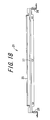
- FIG. 27 is a perspective view of the cover 19
- FIG. 28 is a front view of the cover 19
- FIG. 29 is a rear side view of the cover 19
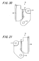
- FIG. 30 is a right side view of the cover 19
- FIG. 31 is a left side view of the cover 19
- FIG. 32 is a plane view of the cover 19.
- the cover 19 is almost a plate, and the projected form on a virtual plane vertical to the thickness direction is substantially rectangular, and the projected form on a virtual plane parallel to both the thickness and longitudinal directions is substantially U-shaped.
- the cover 19 is configured to include a cover bottom section 36, and cover short-side wall sections 37.
- the cover bottom section 36 is provided to be substantially parallel to a virtual plane including short-and long-side directions.
- the short-side When viewed from the thickness direction, the short-side extends in the short-side direction, and the long-side extends in the long-side direction.
- the cover short-side wall sections 37 are coupled to each corresponding end portion of the cover bottom section 36 in the long-side direction, and extend in one thickness direction.
- the cover 19 is provided with fifth attachment sections 110 to be attached with the second engagement members 104 for supporting the first panel holder 21 at both end portions in the long-side direction, i.e., the other side of the short-side direction.
- the second engagement members 104 support the cover 19 to be angularly displaceable against the first panel holder 21.
- the cover 19 can be angularly displaced around the rotation axis line extending in the long-side direction of the other side of the short-side direction, and through angular displacement, the cover 19 is placed over the housing position to the extraction position.
- the cover short-side wall sections 37 are each formed with a sixth attachment section 111 to which a cover guide pin 38 is attached, on each corresponding end portion in the long-side direction, i.e., the other side of the short-side direction.
- the cover guide pin 38 protrudes toward the outside in the long-side direction.
- the cover guide pin 38 is configured to be inserted into the slots 23a and 23b.
- the slot 23a is of the cover guide 23 to be attached to the second panel short-side wall section 29, and the slot 23b is formed to the second panel short-side wall section 29.
- the cover guide pin 38 is guided along the guide slot 23a formed to the cover guide 23.
- the cover 19 is made of a material high in rigidity, e.g., stainless steel plate.
- FIG. 33 is a left side view of the second chassis 15, and FIG. 34 is a schematic plane view of the second chassis 15 and the drive mechanism body 20.
- the second chassis 15 is configured to include a unit 39, the slider 18, and a bottom case 40.
- the unit 39 angularly displaces the first panel holder 21 by a drive force coming from the drive mechanism body 20.
- the slider 18 angularly displaces the first chassis 21 by the drive force coming from the drive mechanism body 20, and the bottom case 40 houses the components.
- FIG. 35 is a plane view of the bottom case 40
- FIG. 36 is a right side view of the bottom case 40
- FIG. 37 is a rear side view of the bottom case 40.
- the bottom case 40 is almost a plate, and the projected form on a virtual plane vertical to the thickness direction is substantially rectangular, and the projected form on a virtual plane parallel to both the thickness and longitudinal directions is U-shaped.
- the bottom case 40 is configured to include a bottom case bottom section 41, and bottom case wall sections 42.
- the bottom case bottom section 41 is provided to be substantially parallel to a virtual plane including short- and long-side directions.
- the short-side When viewed from the thickness direction, the short-side extends in the short-side direction, and the long-side extends in the long-side direction.
- the bottom case wall sections 42 are coupled to each corresponding end portion of the bottom case bottom section 41 in the long-side direction, and extend in one thickness direction.
- the bottom case bottom section 41 On one thickness direction of the bottom case bottom section 41, the components, i.e., the unit 39, the drive mechanism body 20, and the slider 18 are attached.
- the bottom case bottom section 41 is provided with two slider pins 43 along the short-side direction with some space therebetween.
- the slider pins 43 are both protruding in the thickness direction from one end portion of the bottom case bottom section 41 in the vicinity of one side of the long-side direction. These slider pins 43 are used to guide the slider 18 toward the short-side direction of the bottom case 40 by being engaged with the slider 18.
- FIG. 38 is a plane view of the slider 18
- FIG. 39 is a front view of the slider 19
- FIG. 40 is an enlarged front view of a roller pin 44 to be provided to the slider 18.
- the slider 18 is almost a plate, and the projected form on a virtual plane vertical to the thickness direction is substantially U-shaped, and the projected form on a virtual plane parallel to both the thickness and long-side directions is also substantially U-shaped.
- the slider 18 is provided with first to third slide sections 45 to 47. When viewed from the thickness direction, the first slide section 45 extends in the width direction being vertical to the thickness direction, and the second and third slide sections 46 and 47 extend in the length direction vertical to the thickness and width directions, respectively.
- the second and third slide sections 46 and 47 extend from side portions of the first slide section 45 in the width direction.
- the second and third slide sections 46 and 47 are formed with second and third slide wall sections 48 and 49, respectively, each coupled to the external end portions in the width direction and extending in one thickness direction.
- the second slide section 46 is formed with a slider hole 50 that goes through in the thickness direction, and extends along the length direction.
- the second slide section 46 accepts the two slider pins 43 in the slider hole 50. Accordingly, when the slider 18 is attached to the bottom case bottom section 41, the slider 18 is prevented from being displaced against the bottom case 40 in the width direction by the slider pins 43, and is provided to freely slide in the length direction.
- the second slide section 46 is provided with a slide rack 51 serving as a drive rack extending in the length direction from one side portion of the width direction.
- the slide rack 51 meshes with a pinion gear 352 configuring the drive mechanism body 20.
- a slide protruding section 53 is so provided as to protrude in one thickness direction.
- This slide protruding section 53 is formed with a through hole going through in the thickness direction. The through hole is substantially C-shaped when viewed from one thickness direction, and is so formed as to open in the other width direction.
- the slide protruding section 53 can be engaged with a link 66 configuring the unit 39, and when engaged with the link 66, the slider 18 is controlled not to be displaced against the link 66 in the length direction.
- a roller pin 44 is so provided as to protrude in the thickness direction of one end portion. This roller pin 44 engages with the unit 39 when the slider 18 slides in the length direction.
- the roller pin 44 is configured to be able to rotate around the axis line, and to come into contact smoothly with the unit 39.
- a slider guide hole 54 is formed to go through the second slide wall portion 48 in the thickness direction.
- the slider guide hole 54 can be inserted with the slider guide pin 34 provided to the second panel short-side wall section 29, and the slider guide pin 34 supports the first chassis 11 to be angularly displaced freely.
- FIG. 41 is a schematic plane view of the drive mechanism body 20, and FIG. 42 is a schematic front view of the drive mechanism body 20.
- FIG. 42 is a view of the drive mechanism body 20, viewed from one axis line direction of a shaft 55a of a motor 55 serving as the drive source.
- FIG. 41 virtually shows a part of the slider 18.
- the drive mechanism body 20 is configured to include the motor 55, a gear string 56, and a mechanism control section 57.
- the gear string 56 includes a worm gear 58, a clutch 59, an intermediate gear 60, the pinion gear 52, and first and second sensor gears 61 and 62.
- the shaft 55a of the motor 55 is securely fixed with the worm gear 58, and the worm gear 58 meshes with the clutch 59, and then with the intermediate gear 60, the pinion gear 52, the first sensor gear 61, and the second sensor gear 62 so that the drive force is transmitted from the motor 55.
- the pinion gear 52 can be meshed with the slide rack 51 formed to the slider 18.
- the slider 18 slides in the length direction.
- the clutch 59 is provided with a damper mechanism 59a that suppresses any vibration in the axis line direction, thereby transmitting the drive force from the worm gear 58 smoothly to the intermediate gear 60.
- the mechanism control section 57 drives the motor 55 through power supply thereto, and controls the rotation speed of the motor 55.
- the mechanism control section 57 also detects an amount of angular displacement observed to the second sensor gear 62, and based on the detected amount of angular displacement of the second sensor gear 62, controls the rotation direction and speed of the shaft 55a of the motor 55 around the axis line. Accordingly, the mechanism control section 57 exercises control over the placement of the engagement target using the pinion gear 52 for power transmission, and executes the first and second tilting operations.
- FIG. 43 is a schematic plane view of the unit 39
- FIG. 44 is a schematic front view of the unit 39.
- FIGS. 43 and 44 virtually shows a casing member configuring the unit 39.
- the unit 39 is configured to include a sub rack 63, a rack holder 64, an actuation reset spring 65, the link 66, a link guide 67, an idle gear 68, a sector gear 69, the push lever 16, a push lever spring 70, a gear base 71, a cover plate 72, and a side plate 73.
- the sub rack 63 can be engaged with the roller pin 44 of the slider 18.
- the rack holder 64 is fixed to the bottom case 40 for guiding the sub rack 63, and the actuation reset spring 65 provides a spring force to the sub rack 63.
- the link 66 is attached to the rack holder 64, and controls the slider 18 not to be displaced, and the link guide 67 is attached to the sub rack 63 for guiding the link 66.
- the idle gear 68 is meshed with the sub rack 63, and the sector gear 69 is meshed with the idle gear 68.
- the push lever 16 thrusts the thrust sections 17, and the push lever spring 70 provides a spring force to the push lever 16.
- the gear base 71 guides both the sector gear 69 and the push lever 16.
- the cover plate 72 covers the gear base 71, and the side plate 73 is fixed to the rack holder 64 for covering the gear base 71.
- Such a unit 39 is attached to one side of the bottom case 40 in the long-side direction, and specifically, the unit 39 is attached while being abutted the bottom case wall section 42 on one side of the long-side direction, and abutted the bottom case bottom section 41.
- FIG. 45 is a plane view of the sub rack 63
- FIG. 46 is a right side view of the sub rack 63
- FIG. 47 is a front view of a retract lever 74 configuring the sub rack 63
- FIG. 48 is a plane view of the retract lever 74.
- the sub rack 63 is configured to include a sub rack body 75, the retract lever 74, a latch spring 76, and a sub rack pin 77.
- the sub rack body 75 is meshed with both the pinion gear 52 and the idle gear 68.
- the retract lever 74 is provided to the sub rack body 75 to be angularly displaceable.
- the latch spring 76 provides the retract lever 74 with a spring force, and the sub rack pin 77 engages with the rack holder 64.
- the sub rack body 75 is almost a frame, and the projected form on a virtual plane vertical to the thickness direction is substantially rectangular.
- a drive input rack 78 is formed to be meshed with the pinion gear 52, and at the other side of in the short-side direction, a drive output rack 79 is formed to be meshed with the idle gear 68.
- the sub rack body 75 is so provided that the long-side direction thereof becomes substantially parallel to the short-side direction of the bottom case 40.
- one end portion of the actuation reset spring 65 is coupled.
- the other end portion of the actuation reset spring 65 is coupled to the rack holder 64.
- a latch spring housing space 76a is formed in the thickness direction to carry therein the latch spring 76.
- the latch spring 76 is housed in the latch spring housing space 76a, and one end portion thereof in the axis line direction is coupled to the sub rack body 75, and the other end portion thereof in the axis line direction is coupled to the retract lever 74.
- a plurality of sub rack pins 77 are provided along the long-side direction to protrude in one thickness direction.
- the sub rack pins 77 are each inserted into their corresponding sub rack guide slot 85 formed to the rack holder 64, and are controlled not to be displaced against the rack holder 64 in the short-side direction but to freely slide along the long-side direction.
- the retract lever 74 in the attachment state, is provided to be displaceable both in a latch direction 74A being from a latch release position to a latch position, and a latch release direction 74B being from the latch position to the latch release position.
- the retract lever 74 is displaced between the latch position at which the roller pin 44 is latched from the other side of the long-side direction, and the latch release position at which the latching with the roller pin 44 is released.
- the retract lever 74 is almost a plate extending in a rack movement direction, and is formed with a fourth engagement section 113 at one end portion in the longitudinal direction.
- the fourth engagement section 113 is supported by a fourth engagement member 112 attached to the sub rack body 75, i.e., on the other side of the short-side direction, and in the vicinity of the center portion in the long-side direction, to be angularly displaceable.
- the other end portion in the longitudinal direction of the retract lever 74 is protruding in the other long-side direction of the sub rack body 75.
- the retract lever 74 is displaced both in the latch direction 74A and the latch release direction 74B in response when the other end portion thereof in the longitude direction is angularly displaced.
- a protruding portion 74a is formed to protrude in one width direction.
- This protruding portion 74a is coupled with the other end portion of the latch spring 76.
- One end portion of the retract lever 74 in the longitudinal direction is tapered when viewed from the thickness direction. To be more specific, as moving from one side to the other in the longitudinal direction, the retract lever 74 is so formed as to direct in one width direction being orthogonal to both the thickness and longitudinal directions.
- the other end portion of a tapered portion 74b in the other longitudinal direction is formed with a retract concave portion 74c that is dented in the other width direction.
- one end portion of the retract lever 74 is formed in the longitudinal direction, and when the roller pin 44 provided to the slider 18 slides along the long-side direction of the sub rack body 75, i.e., from the other side to one side, the roller pin 44 abuts the tapered portion 74b. Therefore, the roller pin 44 can be displaced to the retract concave portion 74c against the spring force of the latch spring 76. On the other hand, when the roller pin 44 located in the retract concave portion 74c is displaced in the long-side direction, i.e., from one side to the other, the roller pin 44 can slide against the spring force of the latch spring 76.
- the retract lever 74 varies in inclination angle against the sliding direction so that the size of the force bringing the roller pin 44 from the latch position to the latch release position is smaller with the taper portion than with the retract concave portion 74c.
- FIG. 49 is a plane view of the link guide 67
- FIG. 50 is a front view of the link guide 67.
- the link guide 67 is attached to the sub rack 63 as one piece, and guides the link 66 attached to the rack holder 64.
- the link guide 67 is almost a plate extending in the rack movement direction.
- One end portion of the link guide 67 in the longitudinal direction protrudes in the longitudinal direction at one end portion of the sub rack body 75, i.e., on one side of the long-side direction, and the link guide 67 is so coupled that its axis line becomes substantially parallel to the long-side direction of the sub rack body 75.
- the link guide 67 is formed with a link guide slot 80 that goes through in the thickness direction, and extends in the longitudinal direction.
- the link guide slot 80 is inserted with a link pin 81 configuring the link 66.
- the link guide slot 80 is configured to include first, second, and third link guide slot portions 80a, 80b, and 80c along the longitudinal direction from one end to the other.
- the first link guide slot portion 80a extends to be substantially parallel to the longitudinal direction of the link guide 67.
- the second link guide slot portion 80b extends as if inclining in one width direction on the way from the other end portion of the first link guide slot portion 80a in the longitudinal direction toward the other end portion.
- the third link guide slot portion 80c extends from one end portion of the second link guide slot portion 80b in the longitudinal direction to be substantially parallel again to the longitudinal direction of the link guide 67.
- FIG. 51 is a front view of the link 66
- FIG. 52 is a bottom view of the link 66.
- the link 66 is provided to the rack holder 64 so as to be displaceable between a lock position and a lock release position. At the lock position, the slider 18 is blocked from being displaced against the bottom case 40 in the fore-and-aft direction X, and at the lock release position, the slider 18 is allowed to be displaced in the fore-and-aft direction X.
- the link 66 is almost a plate extending in the rack movement direction.
- a lock pin 82 is provided to protrude in the other thickness direction, i.e., on one side of the width direction, and a link pin 81 is also provided to protrude in the other thickness direction, i.e., the other side of the width direction.
- a link support hole 83 is formed to go through in the thickness direction. Through this link support hole 83, a link support pin 84 formed to the rack holder 64 is inserted, and is supported around the axis line thereof so as to be angularly displaceable.
- the lock pin 82 is engaged with a slide protruding section 53 formed to the slider 18 to block the slier 18 from being dispalced.
- the link pin 81 is inserted in a link guide slot 80 formed to the link guide 67.
- the link pin 81 is angularly displaced around the axis line of the link support pin 84.
- FIG. 53 is a plane view of the rack holder 64
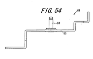
- FIG. 54 is a left side view of the rack holder 64.
- the rack holder 64 is fixed to the bottom case 40 in the attachment state, and slidably supports the sub rack 63.
- the rack holder 64 is almost a plate, and the projected form on a plane vertical to the thickness direction is substantially rectangular.
- the rack holder 64 is formed with a sub rack guide slot 85 that goes through in the thickness direction, and extends in the long-side direction along which the long side thereof extends to guide the sub rack pin 77.
- the sub rack guide slot 85 extends from the center portion of the rack holder 64 in the short-side direction, i.e., direction along which the short side extends when viewed from the thickness direction.
- the rack holder 64 is fixed to the bottom case 40 in the state that its long-side direction is substantially parallel to the short-side direction of the bottom case 40.
- an idle gear placement space 68a is formed to be able to carry therein the idle gear 68.
- the idle gear placement space 68a is going through in the thickness direction.
- the idle gear 68 whose rotation axis line is located in one thickness direction can be engaged with the drive output rack 79 of the sub rack 63 provided to the other thickness direction.
- the other end portion of the actuation reset spring 65 is coupled on one end portion of the rack holder 64 in the long-side direction.
- the actuation reset spring 65 is disposed on the other thickness direction.
- a link support pin 84 is provided to protrude in one thickness direction. In the attachment state, the link support pin 84 is inserted into the link support hole 83 of the link 66, and supports the link 66 against the rack holder 64 so as to be angularly displaceable.
- a link pin insertion hole 86 is formed to go through in the thickness direction.
- the link pin 81 is inserted into the link pin insertion hole 86, and then is inserted into the link guide slot 80 after protruding in the other thickness direction of the rack holder 64.
- a lock pin insertion hole 87 is formed, and in the attachment state, the lock pin 82 is inserted into the lock pin insertion hole 87 to protrude in the other thickness direction of the rack holder 64.
- FIG. 55 is a front view of the sector gear 69
- FIG. 56 is a cross sectional view of the sector gear 69 cut along a cut line S55-S55 of FIG. 55.
- the sector gear 69 is provided with a sector gear roller pin 88 that meshes with the idle gear 68, and protrudes in one thickness direction of the circumferential center potion.
- the sector gear roller pin 88 abuts the push lever 16, and thus the sector gear 69 is displaced around the axis line toward one rotation direction. In this manner, the push lever 16 is thrusted in the thrust direction P1, and when the angular displacement of the sector gear 69 is made toward the other rotation direction, the thrust force acted on the push lever 16 is released.
- FIG. 57 is a front view of the push lever 16
- FIG. 58 is a plane view of the push lever 16.
- the push lever 16 is supported slidably in the thrust direction P1 in response to angular displacement of the sector gear 69.
- the push lever 16 is a plate extending in the axis line direction, and a plurality of, two in this embodiment, push lever guide slots 89 extending in the axis line direction are formed at regular intervals in the width direction.
- the push lever guide slots 89 are formed to accept therein a guide shaft 90 provided to the side plate 73.
- a first coupling section 114 is formed for coupling with one end portion of the push lever spring 70.
- the other end portion of the push lever spring 70 is coupled to a second coupling section 115 formed to the side plate 73, and provides the push lever 16 with a spring force directing toward the thrust release direction P2 being opposite to the thrust direction P1.
- a push lever concave section 91 which is dented inward in the width direction.
- the push lever concave section 91 is always abutted so that the thrust force is provided in the thrust direction P1 against the spring force of the push lever spring 70.
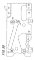
- FIG. 59 is a front view of the side plate 73
- FIG. 60 is a right side view of the side plate 73.
- the side plate 73 moves in concert with the gear base 71, and forms a placement space to carry therein the push lever 16. In this placement space, the push lever 16 is slidably supported.
- the side plate 73 is used as positioning means with respect to the bottom case 40, and in the attachment state, is fixed to the predetermined position of the bottom case 40.
- the side plate 73 is almost a plate, and the projected form on a plane vertical to the thickness direction is substantially rectangular.
- the side plate 73 is so attached that its long-side direction becomes substantially parallel to the short-side direction of the bottom case 40, and its short-side direction to the thickness direction of the bottom case 40.
- the side plate 73 is provided with a plurality of guide shafts 90, e.g., two in this example, at regular intervals in the long-side direction substantially at the same positions in the short-side direction.
- the guide shafts 90 are protruding in one thickness direction. In the attachment state, the guide shafts 90 are each inserted into their corresponding push lever guide slot 89.
- the push lever 16 slides against the side plate 73 in the inclined direction toward one short-side direction on the way from one side to the other in the long-side direction.
- the first coupling section 114 is formed to be coupled with the other end portion of the push lever spring 70.
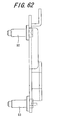
- FIG. 61 is a front view of the gear base 71
- FIG. 62 is a right side view of the gear base 71.
- the gear base 71 is fixed to the side plate 73, and supports the sector gear 69 and the idle gear 68 so as to be angularly displaceable.
- the gear base 71 is almost a plate, and the projected form on a plane vertical to the thickness direction is substantially rectangular.
- the gear base 71 is fixed to the side plate 73 in such a manner that the long- and short-side directions are substantially parallel to the long- and short-side directions of the side plate 73, respectively.
- the gear base 71 is provided with a sector gear-gear shaft 92 protruding in one thickness direction, and an idle-gear gear shaft 93.
- the sector-gear gear shaft 92 is inserted into the sector gear 69, and supports the sector gear 69 so as to be angularly displaceable around the rotation axis line.
- the idle-gear gear shaft 93 is inserted into the idle gear 68, and supports the idle gear 68 so as to be angularly displaceable around the rotation axis line.
- the gear base 71 is formed with a gear base insertion hole 94 into which the sector gear roller pin 88 is inserted.
- the gear base insertion hole 94 is inserted with the sector gear roller pin 88, and when the sector gear 69 makes any angular displacement, is deformed to accept displacement of the sector gear roller pin 88, e.g., arc-shaped in this embodiment.
- the sector gear roller pin 88 abuts the push lever concave section 91 formed to the push lever 16 while being inserted in the gear base insertion hole 94, thereby enabling to thrust the push lever concave section 91.
- FIG. 63 is a plane view of the cover plate 72
- FIG. 64 is a front view of the cover plate 72.
- the cover plate 72 is fixed to the side plate 73 and the gear base 71, and moves in concert with the gear base 71 to form a placement space in which the sector gear 69 and the idle gear 68 can be disposed.
- the cover plate 72 is almost a plate, and the projected form on a plane vertical to the thickness direction is substantially rectangular.
- the side plate 73 is fixed to the side plate 73 and the gear base 71 in such a manner that the long- and short-side directions become substantially parallel to the long- and short-side directions of the gear base 71, respectively.
- the cover plate 72 is provided to cover the sector gear 69 and the idle gear 68 as if covering from the respective rotation axis line directions.
- the first and second tilting operations are described using the directions of the device body 14, i.e., fore-and-aft direction X, vertical direction Z, and lateral direction Y.
- FIG. 65 is a front view for illustrating a tilting operation
- FIG. 66 is a plane view for illustrating the tilting operation.
- FIGS. 65 and 66 both show the device in the first tilting operation. The placement relationship among the components is first described, and then the operation of the components is described.
- the slider 18 can slide both in a first direction toward the front X1 from a contracting position to an expanding position, and in an opposite second direction toward the rear X2 from the expanding position to the contracting position by the slider pin 43 and the slider hole 50 (refer to FIG. 1).
- the slider pin 43 on the front X1 abuts the rear end of the slider hole 50
- the slider pin 43 on the rear X2 abuts the front end of the slider hole 50.
- the sub rack 63 can slide from the front X1 to the rear X2.
- the front X1 is directed from the full-actuation position to the no-actuation position
- the rear X2 is directed from the no-actuation position to the full-actuation position.
- the sub rack pin 77 on the front X1 abuts the front end portion of the sub rack guide slot 85
- the rear end portion of the push lever guide slot 89 abuts the guide shaft 90.
- the actuation reset spring 65 and the latch spring 76 are each set to a spring force that allows any displacement of the retract lever 74 in the latch release direction 74B while blocking the sub rack 63 from being displaced in the rear X2.
- the meshing with the pinion gear 52 is released.
- the drive input rack 78 is meshed with the pinion gear 52.
- the drive output rack 79 formed to the sub rack 63 is located closer to the no-actuation position than the drive output start position, which is closer to the full-actuation position than the drive input start position, the meshing with the idle gear 68 is released, and when located closer to the full-actuation position than the drive output start position, the drive output rack 79 is meshed with the idle gear 68.
- the sub rack 63 receives the spring force directing toward the front X1 from the actuation reset spring 65. Accordingly, in the state that no thrust power of the roller pin 44 is acting, and in the state that the racks are not meshed with their each corresponding gear, the sub rack 63 remains at the no-actuation position, and is prevented from unnecessarily being displaced therefrom.
- the push lever 16 serves as a second tilt actuation section that angularly displaces the first panel holder 21 by the drive force coming from the drive mechanism body 20.
- the push lever 16 can be displaced in both the thrust direction P1, and the thrust release direction P2.
- the thrust direction P1 is directed from a shelter position to a protruding position
- the thrust release position P2 is directed from the protruding position to the shelter position by the push lever guide slot 89 and the guide shaft 90.
- the thrust section 17 At the protruding position, the thrust section 17 is fully pressed toward the front X1, and at the shelter position, the thrust force applied to the thrust section 17 toward the front X1 is released.
- the guide shaft 90 abuts the rear end portion of the push lever guide slot 89 so that the push lever 16 is controlled not to be displaced in the thrust direction P1.
- the guide shaft 90 abuts the front end portion of the push lever guide slot 89 so that the push lever 16 is controlled not to be displaced in the thrust release direction P2.
- the push lever 16 is provided with a spring force toward the thrust release direction P2 by the push lever spring 70.
- FIG. 69 is a plane view for illustrating the tilting operation, showing the slider 18 positioned at the contracting position, and the push lever 16 positioned at the protruding position.
- FIG. 70 is a front view for illustrating the tilting operation, showing the slider 18 positioned at the contracting position, and the push lever 16 positioned at the protruding position.
- the link pin 81 is displaced around the axis line of the link support pin 84 by the link guide slot 80 formed to the link guide 67, and the lock pin 82 is brought from the lock release position to the lock position.
- the lock pin 82 comes to the lock position, the lock pin 82 is engaged with the slide protruding section 53 so as to control the slider 18 from being displaced in the fore-and-aft direction X.
- the first panel holder 21 is angularly displaced.
- Such an angular displacement is made from the closed position along the second panel holder 22 into a direction that the other side portion of the first panel holder 21 is angularly displaced away from the other side portion of the second panel holder 22 around the rotation axis line of the first and second panel holders 21 and 22 at their one side portions.
- the cover 19 is pulled out or housed in response to any angular displacement observed to the first panel holder 21.
- the first panel holder 21 is positioned at the open position by the pinion gear 52 rotating in one rotation direction, and by the push lever 16 being positioned at the protruding position.
- the push lever 16 is positioned at the protruding position, if the pinion gear 52 is displaced toward the other rotation direction R2, the slider 18 is brought to the expanding position in inverse order.
- the roller pin 44 is controlled from being displaced toward the front X1 by the retract lever 74. This is because the retract lever 74 is positioned at the latch position.
- the roller pin 44 thrusts the retract lever 74 toward the front X1 so that the sub rack 63 is brought to the no-actuation position.
- the retract lever 74 is displaced in the latch release direction 74B, and the slider 18 is smoothly displaced in the front X1 so that the sub rack 63 is also brought to the no-actuation position. As such, a transition is made from the second to first tilting operation.
- the first tilting mechanism section for the first tilting operation is implemented by including the slider 18, the first chassis guide pin 32, and the first chassis guide slot 33.
- the second tilting mechanism section for the second tilting operation is implemented by including the first and second panel holders 21 and 22, the cover 19, the second tilt reset spring 24, the push lever 16, the sector gear 69, and the roller pin 44.
- the first tilting mechanism section is operable by the components not including the unit 39, and thus is driven by the drive mechanism body 20 no matter whether the unit 39 is attached thereto.
- the first drive system is implemented by the slide rack to transmit the drive force from the drive source to the first tilting mechanism section.
- the second drive system is implemented by the drive input rack to transmit the drive force from the drive source to the second tilting mechanism section.
- the components i.e., the sub rack 63, the actuation reset spring 65, the retract lever 74, the latch spring 76, and the link 66 all serve as a switch section for switching between first and second drive states.
- the switch section switches back and forth between the first and second drive systems for the connection with the drive source with the panel display 13 positioned at the reference position.
- the tilting apparatus 10 cannot execute the first and second tilting operations at the same time.
- the first tilting operation is not executable, but is possible when the first chassis is at the reference position by rotating the pinion gear 52 in the other rotation direction.
- the second tilting operation is not executable when the first tilting operation is in process because the push lever 16 is never displaced, but is possible when the first chassis is at the reference position by rotating the pinion gear 52 in one rotation direction.
- the push lever 16 When a command comes for the first tilting operation during the second tilting operation, the push lever 16 is brought to the shelter position to put back the first panel holder 21 to the reference position for the first tilting operation thereafter.
- the first chassis When a command comes for the second tilting operation during the first tilting operation, the first chassis is put back to the reference position for the second tilting operation thereafter.
- FIG. 71 is a block diagram showing the electrical configuration of the vehicle-mounted audio device 12
- FIG. 72 is a diagram showing an exemplary operation screen to be displayed by the panel display 13 of the vehicle-mounted audio device 12.
- the vehicle-mounted audio device 12 is configured to include the tilting apparatus 10, the panel display 13, the main control section 95, and a media-reading drive 96.
- the panel display 13 is provided with a switch 97, a touch panel 98, and a liquid crystal display 99.
- the main control section 95 is provided with operation information.
- the liquid crystal display 99 displays thereon information provided by the main control section 95.
- the drive 96 reads information in various media, and forwards the information to the main control section 95.
- the main control section 95 is implemented by a processing circuit such as a microcomputer, and exercises control over other components.
- the main control section 95 forwards control information to the tilting apparatus 10 to exercise control thereover.
- the main control section 95 issues a command against a mechanism control section 57 based on information provided by the mechanism control section 57 equipped in the drive mechanism body 20 of the tilting apparatus 10. After such command issuance, the main control section 95 rotates the pinion gear 52 to exercise control over the placement state.
- the panel display 13 can be thus positioned with any desired angle.
- the panel display 13 when an operation transition is made from the first to second tilting operation, the panel display 13 is first positioned at the reference position, and then the tilting operation is started for the transition destination.
- the first and second tilting operations are started with the reference position always as an operation start position so that the panel display 13 is not unnecessarily displaced.
- the panel display 13 thus can be always at any desired position, and users can place the panel display 13 at the position easy to see, e.g., position with no sun ray reflection.
- one side portion is angularly displaced with respect to the other side portion, thereby preventing the panel display 13 from making any extra movement other than the first and second tilting operations with respect to the device body 14.
- the panel display 13 is not unnecessarily displaced against the device body 14 during the first and second tilting operations, e.g., displaced along the front X1, and juts from the device body 14. This thus favorably leads to the operation with stability.
- the panel display 13 is subjected to the first and second tilting operations through mechanical driving. Unlike any existing technology of executing a tilting operation manually, in the invention, the operations can be thus put into action with more stability. Accordingly, the panel display 13 can be positioned with ease at wherever users want, and is prevented from being unnecessarily displaced after positioned as the users wanted.
- the first and second tilting operations are not allowed to be put into action at the same time. Therefore, the panel display 13 is prevented from being unnecessarily moving displaced the device body 14 as a result of the first and second tilting operation being put into action at the same time. This thus favorably leads to the operation with stability.
- the first and second tilting operations can be both put into action at a reference position.
- the tilting operations can be started at the reference position, if one tilting operation is in process not with the reference position, the remaining tilting operation can be prohibited for execution.
- implemented is the tilting apparatus 10 with which the first and second tilting operations are not allowed at the same time.
- the first and second tilting operations can be put into action in a row with a reference position of the panel display 13 as a wrap-around position.
- the panel display 13 can be smoothly operated for placement at wherever users want.
- first and second tilting operations are put into action using their each provided device, i.e., first and second mechanism bodies. This allows the first and second tilting operations to be individually put into action.
- the second tilting mechanism section can go through the second tilting operation without affecting the first tilting mechanism section for the first tilting operation.
- the second panel holder 22 is not angularly displaced as a result of the first tilting operation, thereby allowing the first tilting operation without the second tilting operation.
- a provision of the cover 19 is protecting the area between the first and second panel holders 21 and 22 from any unwanted dust or foreign substances.
- the tilting apparatus 10 and the vehicle-mounted audio device 12 will suffer from no problem as are being free from foreign substances, and thus their maintenance is easy.
- the cover 19 is made of a rigid material, the second tilting mechanism section can be thus high in rigidity, and the tilting apparatus 10 is protected from damage by external forces acting thereon.
- the cover 19 also prevents the panel display 13 from being unnecessarily displaced during the second tilting operation by external forces acting thereon.
- the cover 19 serves well not to allow foreign substances to enter, and to stop the panel display 13 being displaced. This favorably eliminates the need to newly provide a member for increasing the rigidity of the second tilting mechanism section so that the manufacturing cost can be reduced for the tilting mechanism.
- the cover 19 can cover the area between the first and second panel holders 21 and 22.
- the cover 19 is pulled out or housed in response to the angular displacement made by the first panel holder 21.
- the cover 19 thus covers a gap happened to be formed between the first and second panel holders 21 and 22 without affecting the first tilting operation.
- the cover 19 can be operated in relation to the second tilting operation without any specific operation therefor, in other words, without driving the cover 19 individually. This favorably simplifies the configuration of the tilting apparatus 10.
- At least either a portion guided by the cover guide 23 or the cover guide 23 is made of a material of low friction resistance.
- This configuration enables to suppress any possible noise and impact as a result of section abutment as soon as possible. Such suppression accordingly protects users from noise as a result of the second tilting operation so that the users can be free from annoyance, and the second tilting operation can be smoothly put into action.
- the drive source for use for the second tilting operation can be reduced in nominal output as much as possible, thereby allowing the size reduction of the tilting apparatus 10, and the manufacturing cost reduction.
- the first tilting mechanism section is driven by the drive mechanism 20 no matter if the unit 39 is attached thereto or not, whereby the first tilting mechanism section can individually operate.
- the mechanism body can be made capable of the first and second tilting operations.
- the second panel holder 22 can be angularly displaced from the closed to open position.
- the second tilt reset spring 24 can serve to angularly displace the second panel holder 22 from the open to closed position.
- the second tilt reset spring 24 is the one providing the first panel holder 21 with a spring force toward the rear X2.
- the angular displacement of the first panel holder 21 can be reduced in degree against the displacement of the push lever 16 in the thrust direction P1. Accordingly, even if the push lever 16 is greatly displaced, the first panel holder 21 is not angularly displaced that much. This accordingly eases the positioning of the first panel holder 21 with high precision without exercising control over the displacement of the push lever 16 with high precision, thereby increasing the reproducibility of the positioning of the first panel holder 21. As such, without the need for controlling the displacement of the push lever 16 with high precision, the positioning precision can be increased for the first panel holder 21.
- either a portion of the first panel holder 21 abutting the push lever 16, or a portion of the push lever 16 abutting the first panel holder 21 is made of a material of low friction resistance.
- This configuration enables to suppress any possible collision noise and impact as a result of section abutment as soon as possible. Such suppression accordingly protects users from collision noise as a result of section abutment so that the users can be free from annoyance.
- the angular displacement of the first panel holder 21 can be smooth from the closed to open position. This can reduce the nominal output of the drive source as much as possible for angularly displacing the first panel holder 21, thereby allowing the size reduction of the tilting apparatus 10, and the manufacturing cost reduction.
- a switch section is provided for switching between a first drive state in which the drive force is transmitted to the first tilting mechanism section, and a second drive state in which the drive force is transmitted to the second tilting mechanism section.
- the drive force from a piece of drive mechanism body 20 enables the first and second tilting operations both in a row, thereby requiring only one drive mechanism body 20. That means the drive mechanism body 20 can be shared for use so that the operation control becomes simpler. As a result, the configuration of the tilting apparatus 10 can be also simplified. By sharing the drive mechanism body 20 as such, the tilting apparatus 10 can be reduced in size in its entirety.
- the engagement with the pinion gear 52 is released when the slider 18 is located closer to the contracting position than the branch position.
- the slider 18 is unstable in the vicinity of the branch position, when the sub rack 63 is displaced toward the rear X2, the retract lever 74 slides the slider 18 from the branch to the contracting position via the roller pin 44. This prevents any unnecessary displacement of the slider 18 so that the components are not affected for displacement, and can be smoothly operated.
- the lock pin 82 blocks the slider 18 from being displaced in the fore-and-aft direction X after the slider 18 is disposed at the contracting position so that the slider 18 is not unnecessarily displaced from the contracting position.
- the first and second operations can be thus free from problems that are often caused by the slider 18 being displaced when not desired.
- the components are all substantially a plate, and are substantially L-shaped when viewed from the front X1.
- the unit 39 can be thus attached using the gap space in the device body 14. As such, without greatly changing the configuration of the existing tilting apparatus 10 being capable only of the first tilting operation but only by placing the unit 39 in the gap space, the tilting apparatus 10 becomes capable of the second tilting operation.
- the moving section is exemplified by the panel display 13, and the first panel holder 21 keeping hold of the panel display 13.
- This configuration is surely not restrictive, and the moving section may be implemented only by the panel display 13, or only by the operation section and a first panel holder keeping hold of the operation section.
- the electronic apparatus is exemplified by the vehicle-mounted audio device 12.
- audio devices may not be of vehicle-mounting type, or display units such as television device will do.
- FIGS. 73A to 73F are all a schematic side view of a vehicle-mounted audio device 200 according to another embodiment of the invention.
- the vehicle-mounted audio device 200 is provided with: the second panel holder 22, a first drive section (not shown), and a second drive section (not shown).
- the second panel holder 22 supports, at both ends, both the panel display 13 serving as a moving body, and the first panel holder 21 supporting the panel display 13 so that both of the panel display 13 and the first panel holder 21 can be angularly displaced.
- the first drive section performs the first tilting operation by displacing one side of the second panel holder 22 toward the front, and inclining the components, i.e., the panel display 13, the first panel holder 21 holding the panel display 13, and the second panel holder 22 supporting the first panel holder 21.
- the second drive section performs the second tilting operation by displacing the other side of the respective components, i.e., the panel display 13, and the first panel holder 21 keeping hold of the display 13, moving the other side of the first panel holder 21 away from the other side of the second panel holder 22, and angularly displacing the panel display 13, and that of the first panel holder 21.
- the first drive section may be driven to displace the components, i.e., the panel display 13, and the first and second panel holders 21 and 22, from their reference positions along one surface portion.
- the components, i.e., the panel display 13, and the first and second panel holders 21 and 22, may be displaced in such a manner that their one side portions come closer to the front X1 than their remaining side portions, and the second drive section is driven.
- the remaining side portions of the components, i.e., the panel display 13, and the first panel holder 21 may be displaced so as to be disposed toward the front with respect to the other side portion of the second panel holder 22.
- the components i.e., the panel display 13, and the first and second panel holders 21 and 22, are displaced from their reference positions along one surface portion.
- the second drive section is driven, and the components, i.e., the panel display 13, and the first panel holder 21, may be displaced in such a manner that their other side portions come closer to the front X1 than the other side portion of the second panel holder 22.
- the first drive section may be driven to bring one side portions of the components, i.e., the panel display 13, and the first and second panel holders 21 and 22, toward the front X1.
- the panel display 13 and the first panel holder 21 may be so configured that their side portions are displaced each separately.
- Such a configuration requires at least two sets of drive source and drive mechanism, one for the first tilting operation of the components, i.e., the panel display 13, and the first and second panel holders 21 and 22, and the other for the second tilting operation of the components, i.e., the panel display 13, and the first panel holder 21.
- the set of drive source and drive mechanism for the second tilting operation is required to be equipped not to the device body but to the components, i.e., the panel display 13, and the first and second panel holders 21 and 22.
- Such a configuration favorably increases the placement flexibility for the panel display 13 so that users can makes an angle setting best suiting their needs.
- FIG. 76 is a perspective view of the tilting apparatus 310 according to the second embodiment of the invention.
- FIG. 77 is a cross sectional view of the tilting apparatus 310 cut along a cut line A-A of FIG. 76.
- the tilting apparatus 310 in which a display 311 is configured to be tiltable.
- the tilting apparatus 310 is an apparatus which may be mounted on, for example, a vehicle-mounted audio device serving as an electronic apparatus and prosecutes a tilting operation with respect to a moving body provided in the vehicle-mounted audio device, which is the display 311 in the embodiment of the invention.
- the tilting apparatus 310 includes a support body 312 and a drive source 313.
- the tilting apparatus 310 is so-called a tilting mechanism, and the display 311 is configured to be tiltable therein.
- the tilting apparatus 310 is so configured that the display 311 can be supported by the support body 312.
- the tilting apparatus 310 uses a drive source 313 to drive the display 311 supported by the support body 312 to move at a slant.
- the tilting apparatus 310 is configured to be substantially symmetric with respect to the center line in the width direction of the vehicle, i.e., substantially symmetric in one and the other width directions.
- the tilting apparatus 310 is shown only by one cross section in one width direction, and the remaining cross section in the other width direction may not be shown.
- FIG. 78 is a perspective view of the display 311
- FIG. 79 is a side view of the display 311 viewed in the width direction.
- the display 311 is substantially a rectangular parallelepiped, and the cross section cut along a virtual plane vertical to the thickness direction is substantially a rectangular.
- the expression of “substantially rectangular parallelepiped” includes a rectangular parallelepiped, and the expression of “substantial rectangular” includes being rectangular.
- the display 311 is formed with a display section 314 on a surface portion vertical to the thickness direction.
- the display 311 includes first and second side surface sections 315 and 316 both vertical to the width direction, and the first and second side surface sections 315 and 316 are each formed with a pair of guide sections 317.
- the guide section 317 serving both as a rotation axis and an engagement section is formed to be substantially circular cylindrical.
- the expression of “substantially circular cylindrical” includes being circular cylindrical.
- a pair of guide sections 317a, 317b are disposed at the vicinity of one and the other end portions of the display 311 with a space therebetween in the height direction. These guide sections 317a, 317b are disposed to be closer to the rear surface portion, being opposite to the surface portion formed with the display section 314, and the center axis of the guide sections 317a, 317b is to be substantially parallel to the width direction of the display 311. The expression of "substantially parallel” includes being parallel.
- a pair of guide sections 317c, 317d are disposed at one and the other end portions of the display 311 with a space therebetween in the height direction.
- These guide sections 317c, 317d are also disposed to be closer to the rear surface portion, and the center axis of the guide sections 317c, 317d is also to be substantially parallel to the width direction of the display 311.
- the expression pf "substantially parallel” includes being parallel.
- a pair of the guide sections 317 are formed as if externally protruding in the width direction of the display 311 by a predetermined length.
- These two guide sections 317 are formed to the first and second side surface sections 315 and 316 so as to be symmetric with respect to the substantial center of the display 311 in the width direction.
- the guide section 317 to be formed to the vicinity of one end portion of the first side surface section 315 in the height direction may be referred to as a first guide portion 317a
- the guide section 317 to be formed to the vicinity of the other end portion thereof may be referred to as a second guide portion 317b.
- the guide section 317 to be formed to the vicinity of one end portion of the second side surface section 316 in the height direction may be referred to as a third guide portion 317c, and the guide section 317 to be formed to the vicinity of the other end portion thereof may be referred to as a fourth guide portion 317d.
- the guide sections 317 are not restrictive to those provided to the surface portions of the display 311 being vertical to the width direction, and may be provided to the surface portions of the display 311 being vertical to the height direction.
- the guide sections 317 are provided to each side surface portions of the display 311 at the vicinity of one and the other end portions in the width direction in such a manner that the center axis of the guide sections 317 becomes substantially parallel to the height direction of the display 311 toward the rear surface portion opposite to the surface portion formed with the display section.
- the guide section 317 includes a guide axis 318, an axial spring member 31.9, and an axis cap member 320.
- the first to fourth guide portions 317a, 317b, 317c, and 317d share the same configuration, and described here is only the third guide portion 317c formed at the vicinity of one end portion of the second side surface section 316 in the height direction.
- the remaining guide portions 317a, 317b, and 317d are each provided with the same reference numeral as the third guide portion 317c, and will not be described.
- the guide axis 318 is formed to be substantially circular cylindrical.
- the guide axis 318 is provided at one end portion of the second side surface section 316 in the height direction so as to protrude in the width direction of the display 311, and at the portion closer to the rear surface portion opposite to the surface portion formed with the display section 314.
- the guide axis 318 is so formed that the center axis becomes substantially parallel to the width direction.
- the guide axis 318 is externally provided with the axial spring member 319.
- This axial spring member 319 is a compressed coil spring.
- the axial spring member 319 is a spring being longer than the guide axis 318 in the axis direction.
- the guide axis 318 is provided with the axis cap member 320 for a fit between the axial spring member 319 and the guide axis 318.
- the axis cap member 320 is almost cylindrical with a bottom. One end portion of the axis cap member 320 in the axis direction is formed with a flange.
- the axis cap member 320 is configured to be able to be elastically displaced in the axis direction by elastic resilience biased by the axis spring member 319.
- the axis cap member 320 is made of a material with good slidability, e.g., polyacetal, but such a material is surely not the only option. As such, by the axial spring member 319 and the axis cap member 320 being fit to the guide axis 318, the display 311 is provided with four of the guide section 317.
- FIG. 80 is a cross sectional view of a housing cabinet 321 cut along the cut line A-A of FIG. 76.
- FIG. 81 is a side view of a first slide member 334a viewed in the thickness direction.
- FIG. 82 is a side view of a second slide member 334b viewed in the thickness direction.
- FIG. 83 is a perspective view of a base 325. In the below, the description will be given by referring to FIGS. 76 and 77.
- FIG. 84 is an exploded perspective view showing the engagement among the components, i.e., a guide slot sections 332, a first to fourth to-be-engaged portions 336a, 336b, 336c, and 336d, and a guide sections 317.
- FIG. 84 is an exploded perspective view showing the engagement among the components, i.e., a guide slot sections 332, a first to fourth to-be-engaged portions 336a, 336b, 336c, and 336d
- FIG. 85 is an enlarged side view of a region L2 including a first and second slide members 334a and 334b, and the pinion gear 346, viewed from a direction opposite from arrow M.
- FIG. 86 is an enlarged side view of a region L3 including the first and second slide members 334a and 334b, and the extension spring member 351, viewed in the direction of the arrow M.
- FIG. 87 is an enlarged cross sectional view of a region L1 including the first and second to-be-engaged portions 336a and 336b. In the below, the description will be given by referring to FIGS. 76 to 83.
- the support body 312 includes the housing cabinet 321, and a pair of display support bodies 325 composed of a slide support body 334 and base substance 335 described later.
- the housing cabinet 321 serving as a first support member is configured to be able to support and house therein the display 311.
- the housing cabinet 321 is a frame body substantially of a lattice, the cross section of which is substantially rectangular being cut along a virtual plane vertical to the depth direction. In such a housing cabinet 321, as shown in FIG.
- the width direction of the housing cabinet 321 is denoted by an arrow M as M-axis direction
- the depth direction thereof is denoted by an arrow L as L-axis direction
- the height direction thereof is denoted by an arrow N as N-axis direction.
- the direction parallel to the arrow L is denoted as L direction
- the direction parallel to the arrow M is denoted as M direction
- the direction parallel to the arrow N is N direction.
- the housing cabinet 321 is formed with a housing hole 326 inwardly going through in the L direction, and the display 311 is fit thereto. That is, the housing cabinet 321 is so formed as to able to accommodate therein the display 311 by the housing hole 326.
- the cross section of the housing hole 326 cut along a virtual plane being vertical to the L direction is rectangular, and the display 311 is disposed therein in such a manner that the width direction thereof becomes substantially parallel to the M direction.
- the housing cabinet 321 is not restrictive to such a shape.
- the housing cabinet 321 may be of a box cabinet dented in the L direction as long as being able to accommodate therein the display 311.
- the width direction of the display 311 may be simply referred to as M direction.
- the housing cabinet 321 is formed with a guide slot section 332 serving as a guide mechanism.
- the guide slot section 332 is formed to both first and second internal surface sections 327 and 328, which face the housing hole 326 in the housing cabinet 321.
- the housing cabinet 321 is configured to be able to support the display 311 through engagement between the guide slot sections 332 and the guide sections 317.
- the guide slot section 332 serving as a to-be-engaged section for the first support member is formed to be able to engage with the corresponding guide section 317, and to allow the guide section 317 to slide therealong.
- the guide slot section 332 is a slot section slightly dented in the M direction, and is formed by a first slot section 330, and a pair of second slot sections 331.
- the first slot section 330 extends straight in the N direction, and covers most of the first and second internal surface sections 327 and 328 in the N direction.
- the second slot sections 331 extend straight in the L direction to be parallel to each other. One end portion of the respective second slot sections 331 in the L direction externally opens in the L direction.
- the other end portion of one of the second slot sections 31 in the X direction is formed in a row to one end portion of the first slot section 330 in the N direction, and the other end portion of the other of the second slot sections 331 in the L direction is formed in a row to the other end portion of the first slot section 330 in the N direction.
- the guide slot section 332 is formed inside a substantially-horizontally-inverted U-shape guide slot 332.
- the guide slot 332 is formed to open at one and the other ends toward outside in the L direction.
- the outer diameter portion of the guide slot section 332 formed with the first and second slot sections 330 and 331 in a row is formed with a pair of corner sections 333.
- the corner sections 333 are both chamfered, and are so formed as to accept therein a pair of guide sections 317, respectively.
- the space between the corner sections 333 is made substantially the same as the space between the guide sections 317 provided on the each side surface portion (the space between the first guide section 317a and the second guide section 317b, and the space between the third guide section 317c and the fourth guide section 317d ). This allows the guide sections 317 to come off from one or the other end of the guide slot section 332.
- the guide slot section 332 of such a configuration can be engaged with a pair of guide sections 317, and the guide sections 317 are so formed as to freely slide along the guide slot 332.
- the housing cabinet 321 is so configured as to accommodate therein the display 311, and is able to support the display 311 through engagement between the guide slot sections 332 and the guide sections 317.
- the housing cabinet 321 is made of acrylonitrile butadiene styrene resin (ABS resin), for example.
- the display 311 is supported by a slide support body 334 of a pair of display support bodies 325 composed of a slide support body 334 and base substance 335 through engagement with the guide sections 317.
- One of the display support bodies 325 i.e., the slide support body 334 configuring a part of display support body 325a composing a first member, is provided to support the first and third guide portions 317a and 317c through engagement therewith.
- the first and third guide portions 317a and 317c are two of the guide sections 317 formed at one end portions of the display 311 in the height direction.
- the other of the display support bodies 325 i.e., the slide support body 334 configuring a part of display support body 325b composing a second member, is provided to support the second and fourth guide portions 317b and 317d through engagement therewith.
- the second and fourth guide portions 317b and 317d are two of the guide sections 317 formed at the other end portions of the display 311 in the height direction.
- the display support bodies 325a and 3 provided as such are disposed to face each other with a space therebetween in the N direction.
- the display support bodies 325a and 325b are sharing the same configuration, and in the below, the display support bodies 325a and 325b are collectively referred to as the display support body 325, and are not individually described.
- the display support body 325 serving as a second support member includes a slide support body 334, and the base 335.
- the slide support body 334 includes first to fourth slide members 334a, 334b, 334c, and 334d.
- the first and second slide members 334a and 334b are disposed in line in the M direction
- the third and fourth slide members 334c and 334d are disposed in line in the M direction.
- the pair of the first and second slide members 334a and 334b, and the pair of the third and fourth slide members 334c and 334d are disposed on the base 335 with a space therebetween in the L direction.
- the first slide member 334a is substantially a strip-shaped plate extending in the L direction.
- the first slide member 334a is configured to be able to engage the corresponding guide section 317, i.e., the thickness direction being substantially parallel to the M direction, and the width direction being substantially parallel to the L direction.
- the thickness direction of the first slide member 334a may be simply referred to as "M direction", and the width direction thereof as "N direction”.
- the first slide member 334a configured as such includes a first slide member body 335a, a first to-be-engaged portion 336a, and a first rack portion 337a.
- the first slide member body 335a is substantially a strip-shaped plate extending in the L direction.
- the first slide member body 335a is formed with a first guide hole portion 339a in the vicinity of one end portion of a first opposing surface portion 338a in the Z direction.
- the first opposing surface portion 338a is equivalent in meaning to one surface portion vertical to the M direction.
- the first guide hole portion 339a forms a hole going through in the M direction, and the hole is so formed as to extend straight to be substantially parallel to the L direction approximately from one end to the other of the first slide member body 335a in the L direction.
- substantially parallel includes being “parallel”.
- One and the other ends of the first guide hole portion 339a in the L direction are formed to be substantially half-round.
- the first opposing surface portion 338a is formed with a first spring latch axis 340a protruding in the M direction.
- the first spring latch axis 340a is substantially circular cylindrical, and is configured to be able to latch the hook of an extension coil spring.
- the first spring latch axis 340a is formed between the other end of the first slide member body 335a in the L direction and the center portion in the L direction. To be more specific, the first spring latch axis 340a is formed at a position nearly equidistant in the L direction from the other end and the center.
- the first spring latch axis 340a is not necessarily formed at such a position.
- the first to-be-engaged portion 336a is formed as one piece with one end portion of the first slide member body 335a with no height difference therebetween.
- the cross section of the first to-be-engaged portion 336a cut along a virtual plane vertical to the M direction is shaped substantially half-round including a first notch portion 341a.
- the first notch portion 341a is so configured as to be engaged with the corresponding guide section 317.
- the first notch portion 341a is formed by notching the first to-be-engaged portion 336a partially at the rim surface portion in a first notch direction.
- the first notch direction is equivalent in meaning to the direction directing to one end from the other of the first slide member body 335a in the N direction.
- the first notch portion 341a is substantially U-shaped by a first one-side slope portion 342a, a first the-other-side slope portion 343a, and a first partially-spherical portion 344a.
- the first one-side slope portion 342a is formed around the M-axis to slope in one direction
- the first the-other-side slope portion 343a is formed also around the M-axis but to slope in the other direction.
- the first one-side slope portion 342a and the first the-other-side slope portion 343a are so formed that their notch width is narrowed as are directed in the first notch direction.
- the first partially-spherical portion 344a is formed in a row.
- the first partially-spherical portion 344a is in the shape of an arc, and one end portion thereof is formed to be a piece with the first one-side slope portion 342a, and the other end portion thereof is formed to be a piece with the first the-other-side slope portion 343a.
- the first partial-spherical portion 344a is formed to have a radius substantially the same as or larger than that of the guide section 317 so that the guide section 317 can be engaged and supported thereby.
- the notch width of the first notch portion 341a is increased from the first partially-spherical portion 344a toward the aperture portion for engagement with the guide section 317.
- the first to-be-engaged portion 336a is configured to be able to engage and support the guide section 317 by such a first notch portion 341a.
- the first to-be-engaged portion 341a is not restrictive to the type of increasing the notch width from the first partially-spherical portion 344a toward the aperture portion, and the notch width may be fixed.
- a first rack formation surface portion 345a of the first slide member body 335a is formed with a first rack portion 337a to be a piece with the first slide member body 335a, and to protrude in the N direction.
- the first rack formation surface portion 345a is a surface portion being vertical to the first slide member body 335a in the N direction, and is a surface portion on the other end side.
- the first rack portion 337a is so-called a rack gear, and one end portion thereof in the L direction is sloped.
- both surface portions vertical to the M direction thereof are flush with the surface portions of the first slide member body 335a in the M direction, and the other end portion in the L direction is flush with the other end portion of the first slide member body 335a.
- the first rack portion 337a is formed from the other end portion of the first rack formation surface portion 345a in the L direction toward a portion proximal to the center, and is able to be meshed with a pinion gear 346, which will be described later, in the drive source.
- the first slide member 334a is able to engage the guide section 317 by the first to-be-engaged portion, and to mesh with the pinion gear 346 by the first rack portion 337a.
- the first slide member 334a is formed by pressing or barreling, but formation of the first slide member 334a is not restrictive to such pressing or barreling. To form the first slide member 334a, the step of barreling may be skipped, or any step of mechanical processing may be used.
- the second slide member 334b is substantially a strip-shaped plate extending in the L direction, and the length in the L direction is substantially the same as that of the first slide member 334a.
- the second slide member 334b is disposed in line with the first slide member 334a in the thickness direction.
- the second slide member 334b is so configured as to be engaged with the guide section 317, i.e., the thickness direction being substantially parallel in the M direction, and the width direction being substantially parallel in the L direction.
- the thickness direction of the second slide member 334b may be simply referred to as "M direction", and the width direction thereof as "N direction”.
- At one end portion of the second slide member 334b in the L direction is formed with a second to-be-engaged portion 336b including a second notch portion 341b.
- the second to-be-engaged portion 336b is so configured as to be engaged with the corresponding guide section 317.
- the second slide member 334b is notched at its substantial N-direction center portion in a second notch direction so that the second notch portion 341b is formed.
- the second notch direction is directed from one end of the second slide member 334b in the L direction toward the other.
- the second notch portion 341b is substantially U-shaped viewed from the M direction, formed by a second one-side slope portion 342b, a second the-other-side slope portion 43b, and a second partially-spherical portion 344b.
- the second one-side slope portion 342b is formed around the M-axis to slope in one direction, in other words, is formed to gradually slope in one N direction as is directed from one end to the other in the L direction.
- the second the-other-side slope portion 43b is also formed around the M-axis but to slope in the other direction, in other words, is formed to gradually slope in the other N direction as is directed from one end to the other in the L direction.
- the second one-side slope portion 342b and the second the-other-side slope portion 343b are so formed that the notch width is narrowed as are directed in the second notch direction.
- the second partially-spherical portion 344b is formed in a row.
- the second partially-spherical portion 344b is in the shape of an arc, and one end thereof is formed to be a piece with the second one-side slope portion 342b, and the other end thereof is formed to be a piece with the second the-other-side slope portion 343b.
- the second partially-spherical portion 344b is formed to have a radius substantially the same as or larger than that of the guide section 317.
- the second to-be-engaged portion 336b is not restrictive to the type of increasing the notch width from the second partially-spherical portion 344b toward the aperture portion, and the notch width may be fixed.
- the second to-be-engaged portion 336b formed as such can be engaged with the guide section 317 supported by the first notch portion 341a. Once the second to-be-engaged portion 336b is engaged with the guide section 317, the second notch portion 341b covers the guide section 317 to block the guide section 317 not to come off. In other words, together with the first to-be-engaged portion 336a, the second to-be-engaged portion 336b configures a rotatable bearing section 347 on which the guide section 317 can slide. Through the bearing section 347, the guide section 317 goes and fits. Because the guide section 317 is fit to the bearing section 347 as such, the flange portion of the axis cap member 320 is formed larger than the internal diameter of the bearing section 347 not to come off therefrom.
- the second slide member 334b is formed with a second guide hole portion 339b in the vicinity of one end portion of a second no-opposing surface portion 348b in the N direction.
- the second no-opposing surface portion 348b is equivalent in meaning to a surface portion which faces in the M direction to a second opposing surface portion 349b, which is opposing the first opposing surface portion 338a.
- the second guide hole portion 339b forms a hole going through in the M direction, and the hole is so formed as to extend straight to be substantially parallel to the L direction approximately from one end to the other of the second slide member body 334b.
- One and the other end portions of the second guide hole portion 339b in the L direction are formed to be substantially half-round.
- the second guide hole portion 339b is disposed in line with the first guide hole portion 339a, and substantially, is mostly flush therewith. More in detail, the second guide hole portion 339b is so formed that the surface portion vertical to the N direction is flush with the surface portion of the first guide hole portion 339b vertical to the N direction. The second guide hole portion 339b formed as such is formed longer than the first guide hole portion 339a in the L direction.
- a second spring latch axis 340b and a latch axis guide hole section 350 are formed.
- the second spring latch axis 340b is so disposed as to slightly protrude in the M direction in the vicinity of the other end portion in the L direction.
- the second spring latch axis 340b is substantially circular cylindrical, and is so configured as to latch the hook of the extension spring.
- the latch axis guide hole section 350 forms a hole going through in the M direction, and the hole is so formed as to extend straight to be substantially parallel to the second guide hole portion 339b toward one end in the L direction. This hole is extending from the vicinity of the second spring latch axis 340b.
- the first spring latch axis 340a goes as if protruding in the M direction from the second no-opposing surface portion 348b, and in this state, the first spring latch axis 340a is formed to be slidable in the L direction.
- this first spring latch axis 340a one end portion of an extension spring member 351 is latched.
- the other end portion of the extension spring member 351 is latched by the second spring latch axis 340b.
- this extension spring member 351 is so configured as to bias the first slide member 334a with the elastic resilience in the direction opposite to the direction of arrow L.
- the extension spring member 351 is so configured as not, substantially, to be elastically displaced.
- a second rack formation surface portion 345b of the second slide member 334b is formed with a second rack portion 337b.
- the second rack formation surface portion 345b is a surface portion on the other N-direction end side of the second slide member 334b vertical to the N direction.
- the second rack portion 337b is so-called a rack gear, and is so configured as to be always meshed with the pinion gear 346 that can be always meshed with the first rack portion 337a. That is, the second rack portion 337b is so configured as to be meshed with the pinion gear 346 together with the first rack portion 337a, and even if the first rack portion is not meshed with the pinion gear 346, the second rack portion 337b is so configured as to be meshed with the pinion gear 346.
- the second rack portion 337b is formed to a region covering about 3/5 of the second rack formation surface portion 345b from the other end in the L direction.
- the first rack portion 337a is not meshed with the pinion gear 346
- the second rack portion 337b is configured as to be meshed with the pinion gear 346.
- the first slide member 334a is formed by pressing or barreling, for example, but the first slide member 334a is not restrictive to such pressing or barreling.
- the step of barreling may be skipped, or any step of mechanical processing may be used.
- the configuration of the third slide member 334c is similar to that of the first slide member 334b. Therefore, described below are only differences from the first slide member 334a.
- the expression of “first” is changed to “third”, and its reference sign of "a” is changed to "c”.
- the third slide member 334c is formed to be symmetric to the first slide member 334a with a virtual plane vertical to the M direction.
- the configuration of the fourth slide member 334d is similar to that of the second slide member 334b. Therefore, described below are only differences from the second slide member 334b.
- the expression of "second” is changed to "fourth”, and its reference sign of "b” is changed to "d”.
- the fourth slide member 334d is formed to be symmetric to the second slide member 334b with a virtual plane vertical to the M direction.
- the third and fourth slide members 334c and 334d are formed by pressing or barreling.
- These first to fourth slide members 334a, 334b, 334c, and 334d are formed with first to fourth to-be-engaged portions 336a, 336b, 336c, and 336d, and by such to-be-engaged portions, a to-be-engaged section is formed for the second support member.
- the first to fourth slide members 334a, 334b, 334c, and 334d of such a configuration are all disposed to the base 335.
- the base 335 includes a plate-like member 352, a first guide plate 353a, and a second guide plate 353b, all extending in the L direction.
- the plate-like member 352 has almost the same width as the housing cabinet 321, and the cross section cut along a virtual plane vertical to the thickness direction is substantially rectangular.
- the plate-like member 352 is so disposed that the width direction is substantially parallel to the M direction, and the thickness direction is substantially parallel to the N direction.
- the width direction of the plate-like member 352 may be simply referred to as "M direction", and the thickness direction of the plate-like member 352 as "N direction”.
- the first guide plate 353a is a strip-shaped plate extending in the L direction.
- the first guide plate 353a is formed with a pair of first slide guide axes 354a protruding in the thickness direction to the surface portion opposing the second guide plate 353b, i.e., in the M direction.
- the first slide guide axes 354a are both substantially circular cylindrical, and one of the axes is provided at one end portion of the first guide plate 353a in the L direction, and the other is provided with some space from the other first slide guide axis 354a in the L direction.
- the first slide guide axes 354a are configured to be able to sequentially go through the first and second guide hole portions 339a and 339b, and slide the hole portions 339a and 339b in the L direction.
- the first slide guide axes 354b go through the first and second guide hole portions 339a and 339b for support, and allow the first and second slide members 334a and 334b to reciprocate in the L direction.
- the first slide guide axes 354a latch the first and second guide hole portions 339a and 339b, and block the first and second slide members 334a and 334b not to slide.
- the second guide plate 353b is a strip-shaped plate extending in the L direction.
- the second guide plate 353a is formed with a pair of second slide guide axes 354b protruding in the thickness direction to the surface portion opposing the first guide plate, i.e., in the M direction.
- the second slide guide axes 354b are both substantially circular cylindrical, and one of the axes is provided at one end portion of the second guide plate 353b in the L direction, and the other is provided with some space from the other second slide guide axis 354b in the L direction.
- the second slide guide axes 354b are configured to be able to go through the third and fourth guide hole portions 339c and 339d, and slide the hole portions 339c and 339d in the L direction.
- the second slide guide axes 354b go through the third and fourth guide hole portions 339c and 339d for support, and allow the third and fourth slide members 334c and 334d to reciprocate in the L direction.
- the second slide guide axes 354b latch the third and fourth guide hole portions 339c and 339d, and block the third and fourth slide members 334c and 334d not to slide.
- the base 335 of such a configuration is formed by, as one piece, the plate-like member 352, and the first and second guide plates 353a and 353b by bending, and the cross section cut along a virtual plane vertical in the L direction looks like substantially U-shape.
- Such a base 335 accepts and supports the first and second slide members 334a and 334b by the first slide guide axes 354a, and accepts and supports the third and fourth slide members 334c and 334d by the second slide guide axes 354b.
- the drive source 313 includes drive unit 355, a worm 356, a worm wheel 357, a spur gear 358, a coupling axis 359, and two of the pinion gear 346.
- the drive source 313 is configured to be able to rotate and drive the two pinion gears 346 by the drive unit 355 via the worm 356 and the worm wheel 357.
- the drive unit 355 is configured to be able to rotate and drive the worm 356.
- the drive unit 355 is configured by a direct-current motor (simply referred to as DC motor), and at the tip end portion of the output axis, the worm 356 is provided around the output axis to freely rotate thereabout.
- the worm 356 is provided with the worm wheel 357, which is always meshed with the worm 356.
- the worm wheel 357 is provided around the center axis to freely rotate thereabout.
- the worm wheel 357 is provided with the spur gear 358, which is always meshed with the worm wheel 357.
- the spur gear 358 is provided with the coupling axis 359 to make it go through the substantial center axis.
- the coupling axis 359 is substantially circular cylindrical extending in the M direction, and is so configured as to rotate as one piece with the spur gear 358 about the center axis.
- the coupling axis 359 is provided with the pinion gears 346 each at its one and the other ends.
- the two pinion gears 346 coupled as such by the coupling axis 359 are so configured as to rotate together with the coupling axis 359. This allows the pinion gears 346 to rotate as one piece.
- One of these two pinion gears 346 is meshed with the first and second rack portions 337a and 337b, and the other is meshed with the third and fourth rack portions 337c and 337d.
- the drive source 313 configures the two pinion gears 346 to rotate as one piece by the drive unit 355.
- Such components i.e., the worm 356, the worm wheel 357, the spur gear 358, the coupling axis 359, and the pinion gears 346, configure a gear mechanism 360 together with the first to fourth rack portions 337a, 337b, 337c, and 337d, and be able to slide and drive the first to fourth slide members 334a, 334b, 334c, and 334d in the L direction.
- the display 311 is disposed inside of the housing cabinet 321 with a pair of guide sections 317 engaged with the guide slot sections 332. At this time, the display 311 is so disposed that the display section 314 faces the direction indicated by the arrow L of FIG. 76.
- a pair of guide sections 317 are disposed at a pair of corner sections 333 of the guide slot sections 332, respectively.
- four guide sections 317 are engaged to the guide slot sections 332 formed to the first and second internal surface sections 327 and 328, and the display 311 is supported by the housing cabinet 321.
- predetermined position the position of the display 311 at which the four guide sections 317 are engaged with the corner sections 333 of the corresponding guide slot sections 332.
- predetermined position the position of the display 311 at which the height direction of the display 311 becomes substantially parallel to the N direction.
- the first guide portion 317a is engaged with the first slide member 334a.
- the first slide member 334a is disposed by engaging the first to-be-engaged portion 336a with the first guide portion 317a in such a manner that the first notch portion 341a opens toward the direction of arrow N.
- the first notch portion 341a is disposed along the guide slot section 332 to open in the direction of arrow N.
- the first guide portion 317a can come off from the first to-be-engaged portion 336a, and can slide along the guide slot section 332 in the direction of arrow N.
- the first slide member 334a is disposed in line with the second slide member 334b in such a manner that the first opposing surface portion 338a opposes to the second opposing surface portion 349b.
- the second slide member 334b is inserted into the latch axis guide hole section 350 so that the first spring latch axis 340a protrudes in the M direction from the second no-opposing surface portion 348b, and most parts of the first and second guide hole portions 339a and 339b, especially, the surface portions vertical to the N direction will be flush with each other.
- the second to-be-engaged portion 336b is disposed to open in the L direction.
- the second slide member 334b is provided with the pinion gear 346 to always mesh with the second rack portion 337b.
- the pinion gear 346 to be meshed with the second rack portion 337b may be hereinafter referred to as "first pinion gear 346a".
- the first pinion gear 346a is disposed to be able to mesh with the first rack portion 337a.
- the first pinion gear 346a is disposed to the first rack portion 337a in such a manner that at least the first pinion gear 346a is not meshed with the first rack portion 337a.
- the extension spring member 351 is latched to the first and second spring latch axes 340a and 340b.
- the third guide portion 317c is engaged with the third slide member 334c.
- the third slide member 334c is disposed by engaging the third to-be-engaged portion 336c with the third guide portion 317c so that a third notch portion 341c opens along the guide slot section 332 toward the direction of arrow N. With the third slide member 334c disposed as such, the third guide portion 317c can come off from the third to-be-engaged portion 336c, and becomes able to slide along the guide slot section 332 in the direction of arrow N.
- the third slide member 334c is disposed in line with the fourth slide member 334d in such a manner that third and fourth opposing surface positions 338c and 349d are opposing each other.
- the fourth slide member 334d is inserted into the latch axis guide hole section 350 in such a manner that the third spring latch axis 340c protrudes in the M direction from the fourth no-opposing surface portion 348d, and most parts of the third and fourth guide hole portions 339c and 339d, especially, the surface portions vertical to the N direction will be flush with each other.
- the fourth to-be-engaged portion 336d is disposed to open in the L direction.
- the fourth slide member 334d is provided with the pinion gear 346 to always mesh with the fourth rack portion 337d.
- the pinion gear 346 to be meshed with the fourth rack portion 337d may be hereinafter referred to as "second pinion gear 346b".
- the second pinion gear 346b is disposed to be able to mesh with the third rack portion 337c.
- the second pinion gear 346b is disposed to the third rack portion 337c in such a manner that at least the second pinion gear 346b is not meshed with the third rack portion 337c.
- the extension spring member 351 is latched to the third and fourth spring latch axes 340c and 340d.
- first and third slide members 334a and 334c are placed with some space in the M direction, and are substantially parallel to each other.
- the second slide member 334b is disposed in line with the first slide member 334a
- the fourth slide member 334d is disposed in line with the third slide member 334c.
- Such first to fourth slide members 334a, 334b, 334c, and 334d disposed as such are provided to the base 335 by inserting the first slide guide axes 354a into the first and second guide hole portions 339a and 339b, and by inserting the second slide guide axes 354b into the third and fourth guide hole portions 339c and 339d.
- the first and second slide guide axes 354a and 354b are so configured that the first and third slide members 334a and 334c do not slide in the direction opposite to the direction of arrow L from the positions that the first and third notch portions 341a and 341b are being along the first slot section 30.
- first and second slide guide axes 354a and 354b are so disposed that the first slide guide axes 354a are brought to abut one end portion of the first guide hole portion 339a in the L direction to block the sliding displacement in the direction opposite to the direction of arrow L, and the second slide guide axes 354b are brought to abut one end portion of the third guide hole portion 339a in the L direction to block the sliding displacement in the direction opposite to the direction of arrow L.
- Such disposition prevents the guide sections 317 sliding in the first slot section 330 from being unable to be engaged with the first and third to-be-engaged portions 336a and 336c.
- the base 335 is fixed to the device cabinet or vehicle.
- the display support body 325a can be derived in which the base 335 is disposed with the first to fourth slide members 334a, 334b, 334c, and 334d as such, and the first and third guide portions 317a and 317c can be engaged and supported.
- the first and second pinion gears 346a and 346b are coupled together by the coupling axis 359 provided with the spur gear 358.
- the worm wheel 357 is provided to be meshed with the spur gear 358, and the worm wheel 357 is engaged with the worm 357.
- a drive source 313 includes first and second pinion gears 346a and 346b, a spur gear 358, a coupling axis 359, a worm wheel 357, and a drive unit 355.
- the first drive section includes a display support body 325a and a drive section 313a.
- the first and second pinion gears 346a and 346b are to rotate, and the first to fourth slide members 334a, 334b, 334c, and 334d provided to the base 335 are to slide in the L direction.
- the second slide member 334b configures the bearing section 347 together with the first slide member 334a.
- the fourth slide member 334b configures the bearing section 347 together with the third slide member 334c.
- the slide support member 334A is configured to be able to support the first and third guide portions 317a and 317c not to come off by the bearing section 347.
- the second and fourth slide members 334a and 334b are made to move in concert by the first and second pinion gears 346a and 346b. This allows the set of the first and second slide members 334a and 334b, and the set of the third and fourth slide members 334c and 334d to configure the bearing section 347 substantially at the same time.
- the expression of "substantially at the same time” includes being at.the same time.
- the first and third guide portions 317a and 317c to be supported by the bearing section 347 as such slide along the second slot section 331 of the guide slot section 332 when the one-side slide support body 334A is made to slide, and are allowed to come off from the aperture port of the guide slot section 332.
- the first and third guide portions 317a and 317c are configured to be slidable in the L direction together with the slide support body 334A.
- the first and third guide portions 317a and 317c are configured to be slidable in the L direction, and the display 311 is configured to be tiltable.
- the second guide portion 317b is engaged with the third and fourth slide members 334c and 334d
- the fourth guide portion 317d is engaged with the first and second slide members 334a and 334b.
- the other display support body 325b that can engage and support the second and fourth guide sections 317b and 317d.
- the resulting display support body 325b is provided with the drive source 313 which includes the first and second pinion gears 346a and 346b, the spur gear 358, the coupling axis 359, the worm wheel 357, and the drive unit 355, so that the pinion gear 346 is meshed with the display support body 325b.
- the first drive section includes the display support body 325a and the drive section 313a.
- one display support body 325a to be engaged with the first and third guide portions 317a and 317c may be simply referred to as “one-side display support body 325a", and the other display support body 325b to be engaged with the second and fourth guide portions 317b and 317d as “the-other-side display support body 325b”.
- the one-side slide support body 334A in the one-side display support body 325a may be referred to as “one-side slide support body 334A”
- the slide support body 334B in the the-other-side display support body 325b may be referred to as "the-other-side slide support body 334B”.
- the one-side and the-other-side display support bodies 325a and 325b are so disposed as to oppose each other, and to be symmetric with respect to a virtual plane vertical to the N direction.
- the tilting apparatus 310 can be configured.
- FIGS. 88A to 88D are all the cross sectional views of the display 311 in a case where the one-side slide support body 334A is driven to make the display 311 move at a slant, cut along a cut line B-B of FIG. 76.
- FIG 88A is a cross sectional view, cut along the cut line B-B of FIG. 76, of the display 311 at the predetermined position.
- FIG. 88B is a cross sectional view, cut along the cut line B-B of FIG. 76, of the first and third guide sections 334a and 334c being supported by the bearing section 347.
- FIG. 88C is a cross sectional view, cut along the cut line B-B of FIG.
- FIG. 88D is a cross sectional view of the display 311 in a state of moving at a slant, cut along the cut line B-B of FIG. 76. Described now is a case where only the one-side slide support body 325a slides in the L direction, and the display 311 is made to move at a slant in one direction about the M-axis.
- first slide member 334a the components are those provided to the one-side slide support body 334A.
- the tilting apparatus 310 is engaged with the guide sections 317 corresponding to the first and third slide members 334a and 334c of the one-side and the-other-side slide support bodies 334A and 334B.
- the second and fourth slide members 334b and 334d of the one-side and the-other-side slide support bodies 334A and 334B are meshed with and latched by the pinion gear 346 without being engaged with the guide sections 317.
- the extension spring member 351 to be latched to the first to fourth spring latch axes 340a, 340b, 340c, and 340d is in the extended state, and biases the first and third slide members 334a and 334c with the spring force being elastic resilience in the direction opposite to the direction of arrow L.
- the first slide member 334a, second slide member 334b, third slide member 334c and forth slide member 334d will not rattle, and can engage and support the guide sections 317.
- the drive source 313 slides the second and fourth slide members 334b and 334d of the one-side slide support body 334A in the direction of arrow L.
- the fourth slide member 334d is made to slide as such, as shown in FIG. 88B, the bearing section 347 is configured with the third slide member 334a, and the third guide portion 317c is blocked not to come off from the third to-be-engaged portion 336c, and the third guide portion 317c can be supported to be able to rotate.
- the second slide member 334b is made to slide in the same manner, and then the bearing section 347 is configured with the first slide member 334a, and the first guide portion 317a is blocked not to come off from the first to-be-engaged portion 336a, and the first guide portion 317a is supported to be able to rotate.
- This allows the one-side slide support body 334A to support the first and third guide portions 317a and 317c without the possibility of their coming off.
- the first and third slide members 334a and 334c of the the-other-side slide support body 334B do not configure the bearing section 347, the second and fourth guide portions 317b and 317d can be made to come off from the the-other-side support body 334B.
- the first and third guide portions 317a and 317c pushed as such start sliding along the second slot sections 331 of the guide slot sections 332 in the L direction and at the same time, the second guide section 317b and the fourth guide section 317d start moving in the direction of n which is opposite direction of arrow N along the first slot section 330 of the slot section 332, and as shown in FIG. 88C, the display 311 can be made to move at a slant.
- the first slide member 334a is engaged with the first guide portion 317a
- the third slide member 334c is engaged with the third guide portion 317c. Therefore, the first and third slide members 334a and 334c are pushed together with the first and third guide portions 317a and 317c, and start sliding in the L direction.
- the first rack portion 337a is meshed with the first pinion gear 346a
- the second pinion gear 346b is meshed with the third rack portion 337c.
- the first and second slide members 334a and 334b are meshed with the first pinion gear 346a
- the third and fourth slide members 334c and 334d are meshed with the second pinion gear 346b.
- the first and third guide portions 317a and 317c rotate the bearing section 347, slide in the direction of arrow L, and come off from the second slot section 331 of the guide slot sections 332.
- the second and fourth guide portions 317b and 317d come off from the the-other-side slide support body 334B, and slide the first slot section 330 in the direction opposite to the direction of arrow N.
- one end portion of the display 311 in the height direction is displaced in the L direction, and the other end portion thereof is displaced in the N direction.
- the display 311 moves at a slant in one direction about the M-axis.
- the tilting apparatus 310 slides the one-side slide support body 334A by the drive source 313, and can drive the display 311 to move at a slant in one direction about the M-axis.
- the tilting apparatus 310 can make the display 311 move at a slant from the predetermined position in one direction about the M-axis. That is, the tilting apparatus 310 can put back to the predetermined position from the state that the display 311 moves at a slant in one direction about the M-axis.
- the display drive mechanism 311 goes through the operation in the reverse manner to make the display 311 move at a slant in one direction about the M-axis from the predetermined position, and such an operation will be omitted here.
- FIGS. 89A to 89D are all the cross sectional views of the display 311 in a case where the-other-side support body 334B is driven to make the display 311 move at a slant, cut along the cut line B-B of FIG. 76.
- FIG 89A is a cross sectional view, cut along the cut line B-B of FIG. 76, of the display 311 at the predetermined position.
- FIG. 89B is a cross sectional view, cut along the cut line B-B of FIG. 76, of the second and fourth guide portions 317b and 317d being supported by the bearing section 347.
- FIG. 89C is a cross sectional view, cut along the cut line B-B of FIG.
- FIG. 89D is a cross sectional view of the display 311 in a state of moving at a slant, cut along the cut line B-B of FIG. 76. Described now is a case where only the the-other-side slide support body 334B slides in the L direction, and makes the display 311 move at a slant in the other direction about the M-axis.
- first slide member 334a the components are those provided to the the-other-side slide support body 334B.
- the tilting apparatus 310 is engaged with the guide sections 317 corresponding to the first and third slide members 334a and 334c of the one-side and the-other-side slide support bodies 334A and 334B.
- the second and fourth slide members 334b and 334d of the one-side and the-other-side slide support bodies 334A and 334B are meshed with and latched by the pinion gear 346 without being engaged with the guide sections 317.
- the extension spring member 351 to be latched to the first to fourth spring latch axes 340a, 340b, 340c, and 340d is in the extended state, and the spring force being elastic resilience in the direction opposite to the direction of arrow L is biased to the first and third slide members 334a and 334c.
- the first and third slide members 334a and 334c will not rattle, and can engage and support the guide sections 317.
- the drive source 313 slides the second and fourth slide members 334b and 334d of the-other-side slide support body 334B in the direction of arrow L.
- the bearing section 347 is configured with the first slide member 334a, and the fourth guide portion 317d is blocked not to come off from the first to-be-engaged portion 336a, and the fourth guide portion 317d can be supported to be able to rotate.
- the fourth slide member 334d is made to slide in the same manner, and then the bearing section 347 is configured with the third slide member 334c, and the second guide portion 317b is blocked not to come off from the third to-be-engaged portion 336c, and the second guide portion 317b is supported to be able to rotate.
- This allows the the-other-side slide support body 334B to support the second and fourth guide portions 317b and 317d without the possibility of their coming off.
- the first and third guide portions 317a and 317c can be made to come off from the one-side support body 334A.
- the second and fourth guide portions 317b and 317d are pushed in the direction of arrow L.
- the second and fourth guide portions 317b and 317d pushed as such start sliding along the second slot section 331 of the guide slot sections 332 in the L direction, and at the same time, the first guide section 317a and the third guide section 317c start moving in the direction of arrow N along the first slot section 331 of the guide slot section 332, and as shown in FIG. 89C, the display 311 can be made to move at a slant.
- the first slide member 334a is engaged with the fourth guide portion 317d
- the third slide member 334c is engaged with the second guide portion 317b. Therefore, the first and third slide members 334a and 334c are pushed together with the second and fourth guide portions 317b and 317d, and start sliding in the L direction. Once the first and third slide members 334a and 334c slide in the L direction, the first rack portion 337a is engaged with the first pinion gear 346a, and the second pinion gear 346b is meshed with the third rack portion 337c.
- first and second slide members 334a and 334b are meshed with the first pinion gear 346a
- third and fourth slide members 334c and 334d are meshed with the second pinion gear 346b.
- the second and fourth guide portions 317b and 317d rotate the bearing section 347, slide in the direction of arrow L, and come off from the second slot section 331 of the guide slot sections 332.
- the first and third guide portions 317a and 317c come off from the one-side slide support body 334A, and slide in the first slot section 330 in the direction of arrow N.
- the other end portion of the display 311 in the height direction is displaced in the L direction, and the other end portion thereof is displaced in the N direction.
- the display 311 moves at a slant in the other direction about the M-axis.
- the tilting apparatus 310 slides the the-other-side slide support body 334B by the drive source 313, and can drive the display 311 to move at a slant in the other direction about the M-axis.
- the tilting apparatus 310 can make the display 311 move at a slant from the predetermined position in the other direction about the M-axis. That is, the tilting apparatus 310 can put back to the predetermined position the display 311 in a state of moving at a slant in the other direction about the M-axis.
- the display drive mechanism 101 goes through the operation in the reverse manner to make the display 311 move at a slant in the other direction about the M-axis from the predetermined position, and such an operation will be omitted here.
- the tilting apparatus 310 slides the one-side and the the-other-side slide support bodies 334A and 334B substantially at the same time in the direction of arrow L so that the display 311 is not inclined but made to slide in the L direction. As such, the tilting apparatus 310 not only inclines the display 311 but also slides the display 311 in the L direction.
- the tilting apparatus 310 configured as such can make the display 311 move at a slant from the predetermined position in one and the other directions about the M-axis. As such, the display 311 becomes able to move at a slant in a larger range than the tilting apparatus 310 of the conventional technology so that the number of selectable inclination angles can be increased, and at the same time, the electronic apparatus provided with the tilting apparatus 310 can be installed at an angle of increased freedom degree. Accordingly, if the viewability of the display 311 is reduced due to reflections of sun's rays and landscape at the display 311, it becomes possible to increase the viewability by adjusting the inclination angle of the display 311.
- the one-side and the the-other-side display support bodies 334A and 334B are disposed in the vertical direction on one on the other, the display 311 becomes able to move front-upward or front-downward at a slant.
- inclining the display 311 front-downward can suppress such reflections of sun's rays and landscape so that the viewability of the display section 314 of the display 311 can be increased for images for display thereon.
- the display 311 can also be inclined front-upward similarly to an electronic apparatus tilt drive mechanism, and therefore, by adjusting the inclination angle of the display 311 to be inclined front-upward, the level of the viewability similar to that of the conventional technology can be achieved. Furthermore, the electronic apparatus provided with the tilting apparatus 310 can.be installed at an angle of increased freedom degree.
- the direction vertical to a virtual plane including the display section 314 may be inclined not only front and rear but also upward and downward toward the side.
- the display 311 can be inclined upward or downward toward the side.
- the display 311 is made to come into conformity with a user looking at images to be displayed on the display section 314, and inclined sideward to increase the viewability.
- the display 311 may be inclined toward one direction, i.e., right or left, to increase the viewability.
- the display 311 When the display 311 is looked at from the passenger's seat, the display 311 may be inclined toward the other direction, i.e., right or left, to increase the viewability. This is applicable for the rear seats, and the display 311 can be inclined also in the lateral direction so that the viewability can be increased.
- tilting apparatus 310 there may be a case where electronic device is disposed between a pair of display support bodies 325.
- a reproduction device which is not shown, is provided for reproducing optical recording media such as compact disks (CDs), and digital versatile discs (DVDs).
- the reproduction device is formed with an insertion port facing the housing hole 326 to accept therein the optical recording media.
- the tilting apparatus 310 is allowed to be driven to move at a slant in one and the other directions, and when the user finds it difficult to insert the optical medium even if the display 311 is made to move at a slant in one direction, the display 311 may be made to move at a slant in the other direction to ease insertion of the optical medium. Therefore, by configuring the display 311 to be able to move at a slant in both directions, the functionality can be fulfilled as originally intended.
- the electronic device to be provided inside of the electronic apparatus provided with the tilting apparatus 310 is not restrictive to such a reproduction device, and may be electronic device such as personal computer.
- the display 311 When the display 311 is provided with an operation section, the display 311 may be made to move at a slant and the operation section may be placed at any desired position. Accordingly, the operation section can be increased in operability, and the functionality can be thud fulfilled as intended. What is more, the display 311 can be made to slide in the L direction to put the display section 314 closer to the users, thereby leading to the better viewability and operability.
- the tilting apparatus 310 can incline and slide the display 311 in various directions depending on surroundings and circumstances so that the viewability can be increased for the user.
- the guide slot section 332 is formed in the substantially-horizontally-inverted U-shape, the guide section 317 is engaged with the guide slot section 332, and can slide therealong in the L and N directions. Because the one and the other ends of the guide slot section 332 are both open so that the guide section 317 can make the guide slot section 332 come off at one or the other end thereof. As such, the guide section 317 can slide in the guide slot section 332 or come off therefrom, even if the display 311 is formed with two sets of a pair of the guide sections 317, the display 311 can be made to move at a slant and slide in one and the other directions.
- the guide section 317 is formed with the axial spring member 319, and is so configured as to be elastically displaced in the M direction. Accordingly, the guide section 317 is elastically displaced depending on the shape of the guide slot section 332, and can slide in the guide slot section 332, thereby increasing the slidability of the guide section 317.
- the axial cap member 320 and the guide slot section 332 are both made of a material with good slidability, the guide section 317 can be increased in slidability to a further degree. With such an elastic deformation capability, the guide section 317 and the guide slot section 332 are not required to be high in rigidity, i.e., can be formed with no consideration for rigidity. Therefore, the tilting apparatus 310 can be reduced in manufacturing cost.
- the guide sections 317 When the display 311 is at the predetermined position, the guide sections 317 are engaged and supported by the guide slot sections 332 and the first and third slide support members 334a and 334c of the slide support body. In a state that the display 311 moves at a slant, the guide sections 317 are engaged and supported by the slide support members 334 and the guide slot sections 332. As such, the guide sections 317 are engaged and supported by the guide slot sections 332 and the slide support member 334.
- Such a configuration allows reliable engagement and support of the guide sections 317. That is, the display 311 is supported without fail, and is prevented from coming off from the tilting apparatus 310.
- This slide support body 334 is engaged, for support, with the second slide member 334b to prevent the first and fourth guide sections 317a and 317d engaged with the first slide member 334a, from coming off, when the slide support body 334 is made to slide. Accordingly, the first and fourth guide sections 317a and 317d can be held without fail. When not engaged with the second slide member 334b, the first and fourth guide sections 317a and 317d are supported to be able to come off from the first slide member 334a.
- first and second slide members 334a and 334b By using two different members, i.e., first and second slide members 334a and 334b, a switching can be made between the state of securely keeping hold of the first and fourth guide sections 317a and 317d, and the state of allowing the first and fourth guide sections 317a and 317d to come off from the first slide member 334a.
- the second and third guide sections 317b and 317c being engaged with the third slide member 334c is engaged, for support, with the fourth slide member 334d to prevent the second and third guide sections from coming off.
- the guide section 317 When not engaged with the fourth slide member 334d, the guide section 317 is supported to be able to come off from the third slide member 334c.
- the slide support member 334 can switch the state of securely keeping hold of the guide section 317, and the state of allowing the guide section 317 to come off.
- the tilting apparatus 310 can make the display 311 move at a slant in one and the other directions, thereby leading to the manufacturing cost reduction of the tilting apparatus 310.
- the first and third to-be-engaged portions 336a and 336c are formed in the U-shape so that the most parts of the notch portions 341a and 341c are open in the N direction along the first slot section 330. This allows the guide section 317 located at the corner section 333 of the guide slot section 332 to come off from the first or third to-be-engaged section, and to slide in the N direction along the first slot section 330 or in the direction opposite to the N direction. Because the guide section 317 can slide in the N direction or in the direction opposite to the N direction as such, the display 311 can move at a slant from the predetermined position.
- the first to-be-engaged portion 336a is so formed that the notch width is increased from the first partially-spherical portion 344a toward the aperture portion, thereby easing the engagement and coming-off of the first and fourth guide sections 317a and 317d sliding in the guide slot section 332.
- the third to-be-engaged portion 336c is so formed that the notch width is increased from the third partially-spherical portion 344c toward the aperture portion, thereby easing the engagement and coming-off of the second and third guide sections 317b and 317c sliding in the guide slot section 332.
- the first and second slide guide axes 354a and 354b can block the first and third slide members 334a and 334c from sliding, thereby preventing the guide section 317 sliding in the first slot section 330 from being unable to engage with the first and third to-be-engaged portions 336a and 336c.
- the guide section 317 can be smoothly engaged with or made to come off from the first and third to-be-engaged portions 336a and 336c. In other words, this can implement the smooth slant movement of the display 311. What is more, with such a configuration, the tilting apparatus 310 can be implemented without increasing the rigidity of the guide section 317, and the first and third slide members 334a and 334c.
- the second to-be-engaged portion 336b is also formed to have the wider notch width from the second partial-spherical portion 344b toward the aperture portion. This can facilitate the engagement and coming-off of the first and fourth guide sections 317a and 317d sliding in the guide slot section 332.
- the fourth to-be-engaged portion 336d is also formed to have the wider notch width from the fourth partial-spherical portion 344d toward the aperture portion. This facilitates the engagement and coming-off of the second and third guide sections 317b and 317d sliding in the guide slot section 332.
- the tilting apparatus 310 can be implemented without increasing the rigidity of the components, i.e., the guide section 317, and the second and fourth slide members 334b and 334d. As such, there is no more need to increase the rigidity of the first to fourth slide members 334a, 334b, 334c, and 334d, to implement the tilting apparatus 310 so that the manufacturing cost can be favorably reduced.
- the extension spring member 351 is latched to the first and second spring latch axes 340a and 340b, and when the second slide member 334b is not engaged with the first and fourth guide sections 317a and 317d, the extension spring member 351 biases the first slide member 334a with the elastic resilience, i.e., extension force. This makes the first slide member 334a pinch the first and fourth guide sections 317a and 317d, for engagement, together with the guide slot section 332.
- the extension spring member 351 latched to the third and fourth spring latch axes 340c and 340d biases the third slide member 334c with the extension force
- the second and third guide sections 317b and 317c are pinched by the third slide member 334c and the guide slot section 332.
- the guide section 317 is positioned to the corner section 333 of the guide slot section 332 so that the display 311 can be prevented from rattling. This also can suppress image flickering or others on the display section 314, and the viewability is thus increased.
- the guide section 317 can be positioned as such without fail, the guide section 317 can be successfully pinched and supported only by forming the first and third partially-spherical portions 344a and 344c larger than the guide section 317, i.e., there is no more need to form the first and third partially-spherical portions 344a and 344c in conformity with the guide section 317.
- the first and fourth to-be-engaged portions 336a and 336d are not necessarily formed with precision, and are easy to manufacture. In this manner, the display drive mechanism 10 can be implemented without increasing the rigidity of the first and third slide members 334a and 334c.
- the extension spring member 351 latched to the first and second spring latch axes 340a and 340b biases the extension force to control the first and second slide members 334a and 334b not to move away from each other. This prevents the bearing section 347 configured by the first and second to-be-engaged portions 336a and 336b from opening.
- the extension spring member 351 latched to the third and fourth spring latch axes 340c and 340d biases the extension force to control the third and fourth slide members 334c and 334d not to move away from each other.
- the guide section 317 is prevented from coming off from the bearing section 347, and the guide section 317 can be supported by the bearing section 347 with reliability.
- the slide support body 334 is able to fully support the guide section 317.
- the extension force is biased as such, and because the first and second slide members 334a and 334b move in concert with each other, even if the first slide member 334a is not meshed with the first pinion gear 346a, the first and fourth guide sections 317a and 317d can be brought to the corner section 333 of the guide slot section 332 without fail.
- the third and fourth slide members 334c and 334d move in concert with each other, even if the third slide member 334c is not meshed with the second pinion gear 346b, the second and third guide sections 317 can be brought to the corner section 333 of the guide slot section 332 without fail. Accordingly, when the display 311 is to be put away, the display 311 can be put back to the predetermined position without fail.
- the drive source 313 can drive the display 311 to move at a slant with ease.
- the slide support body 334 can be controlled by the sliding amount, and the display 311 can be controlled by the inclination angle.
- the first and second slide members 334a and 334b configure the bearing section 347 from which the first and fourth guide sections 317a and 317d are not allowed to come off even with no engagement.
- the first and second slide members 334a and 334b move in concert to support the first and fourth guide sections 317a and 317c being fit to the bearing section 347 not to make them come off therefrom, and make the guide section 317 slide in the L direction.
- the third and fourth slide members 334c and 334d configure the bearing section 347, and can make the second and third guide sections 317b and 317c being fit to the bearing section 347 slide in the L direction.
- the tilting apparatus 310 can make the display 311 move at a slant and house the display 311 in one and the other directions about the M-axis, and can reliably support the display 311 moving at a slant.
- the guide slot 332 is substantially-horizontally-inverted U-shaped, but this is not restrictive.
- the first slot section 330 may be partitioned in one and the other N directions at substantially the center portion in the N direction. Still alternatively, the first slot section 330 may move at a slant around the M-axis. With this being the case, the formation may be made in conformity with the sliding trace of the guide section 317 when the display 311 moves at a slant.
- the extension spring member 351 is used to bias the first and fourth sliding members 334a, 334b, 334c, and 334d with the elastic resilience. This is surely not restrictive, and as an alternative to the extension spring member 351, rubber or shock absorber will serve well, and any will do as long as the elastic resilience can be biased thereby.
- every display support body 325 is provided with the drive source 313, but this is surely not restrictive.
- the drive unit 355 may be singly provided, and is provided with the worm 356.
- the worm wheel 357 is provided to be meshed with the worm 356.
- the first pinion gear 346a is provided to be meshed with the first and second rack portions 337a and 337b
- the second pinion gear 346b is provided to be meshed with the third and fourth rack portions 337c and 337d.
- the first and second pinion gears 346a and 346b provided as such are coupled together by the coupling axis 359, and the coupling axis 359 is provided with the spur gears 358.
- a gear change mechanism is provided so that the two spur gears 358 can be changed for the meshing combination with the worm wheel 357.
- Such a configuration enables to drive the two display support bodies 325 by the singly-provided drive unit 355. Therefore, the number of components of the tilting apparatus 310 can be reduced, thereby simplifying the configuration. The manufacturing cost can be thus reduced for the tilting apparatus 310 in its entirety.
- every pinion gear 346 may be provided with the drive unit 355, and four of the drive sources 313 may be used.
- the drive source 313 is configured by the drive unit 355 and the gear mechanism 58, but this is surely not restrictive.
- the motor may be provided with a ball screw mechanism, and the slide support body 34 may be driven by thus provided ball screw mechanism.
- the slide support member 334 may be driven using an air cylinder or electric cylinder.
- the tilting apparatus 310 of this embodiment when the display 311 is made to move at a slant, two guide sections 317 are made to slide in the L direction, and any remaining guide sections 317 are made to slide in the N direction. This is surely not the only option, and the display 311 is not necessarily made to move at a slant with such an operation.
- one of the two sets of guide sections 317 e.g., first and third guide sections 317a and 317c
- the other of the two sets of guide sections 317 e.g., second and fourth guide sections 317b and 317d may be configured to be able to rotate around the guide sections 317a and 317c.
- the other set of the guide sections 317 i.e., guide portions 317b and 317d
- one set of guide sections 317 e.g., first and third guide sections 317a and 317c may be configured to be able to rotate around the guide sections 317b and 317d.
- the guide slot section 332 is configured to be able to rotate the second and fourth guide sections 317b and 317d around the supported first and third guide sections 317a and 317c, and to rotate the first and third guide sections 317a and 317c around the supported second and fourth guide sections 317b and 317d.
- This is specifically implemented by forming the second slot section 330 in the shape of an arc.
- the first slot section 330 is not necessarily formed for the guide slot section 332.
- the guide section 317 is engaged to the slide support body 334 to be attachable/detachable thereto/therefrom, but this is surely not restrictive.
- the first and second slide members 334a and 334b may be formed as one piece to configure the bearing section 347, and the resulting bearing section 347 may be fit with the first and fourth guide sections 317a and 317d.
- the third and fourth slide members 334c and 334d may be formed as one piece to configure the bearing section 347, and the resulting bearing section 347 may be fit with the second and third guide section 317b and 317c.
- the display 311 may be made to move at a slant. Accordingly, in this case, the first slot section 330 of the guide slot section 332 may not be necessary.
- the second and third guide sections 317b and 317c can be displaced around the first and fourth guide portions 317a and 317d serving as fulcrums while the first and fourth guide sections 317a and 317d can be displaced around the second and third guide sections 317b and 317c serving as fulcrums. This can incline the display 311 in one direction and the other direction around the M-axis.
- each guide section 317 is formed, but the number of the guide sections is not restrictive to four.
- eight guide sections 317 may be formed in total, e.g., two sets of a pair of guide sections 317 may be respectively formed to each of side surface portions being vertical to the display section 314, and being adjacent to the side surface portions formed with the guide sections 317.
- these sets of guide sections 317 may be also provided with the display support bodies 325 so that the display 311 can be inclined also in one and the other directions around the N-axis.
- the display 311 becomes able to be inclined in various directions, and the display 311 can be conveniently adjusted by inclination angle thereof to a further possible degree than the tilting apparatus 301 of the conventional technology, meeting the requirements such as placement or surroundings. That is, the tilting apparatus can be increased in general versatility.
- the width direction of the display 311 and the housing cabinet 321 is denoted as M-axis direction, and the height direction thereof is as N direction, but this is surely not restrictive.
- the moving section supported by the tilting apparatus 310 is the display 311, but this is surely not restrictive.
- the electronic apparatus may not be necessarily formed with the display section 314, or an operation panel of a reproduction device which is an electronic device provided inside of the electronic apparatus provided with tilting apparatus 310. With this being the case, the reproduction device can be inclined at any optimum inclination angle so that the operability can be increased for insertion/removal of recording media, and for various operation switches.
- the first to fourth slide members 334a, 334b, 334c, and 334d are engaged with the guide sections 317 so that the display 311 is made to slide.
- the first and third slide members 334 may be each provided with an abutment member, and the abutment members may be pushed.
- the guide sections 317 engaged with the first and third slide members 334a and 334c are made to slide so that the display 311 can move at a slant. This can reduce the load possibly imposed on the guide sections 317, thereby favorably protecting the guide sections 317 from damage.
Landscapes
- Engineering & Computer Science (AREA)
- General Engineering & Computer Science (AREA)
- Theoretical Computer Science (AREA)
- Mechanical Engineering (AREA)
- Human Computer Interaction (AREA)
- Computer Hardware Design (AREA)
- Physics & Mathematics (AREA)
- General Physics & Mathematics (AREA)
- Signal Processing (AREA)
- Multimedia (AREA)
- Fittings On The Vehicle Exterior For Carrying Loads, And Devices For Holding Or Mounting Articles (AREA)
- Casings For Electric Apparatus (AREA)
- Devices For Indicating Variable Information By Combining Individual Elements (AREA)
Applications Claiming Priority (3)
| Application Number | Priority Date | Filing Date | Title |
|---|---|---|---|
| JP2005099747A JP4246712B2 (ja) | 2005-03-30 | 2005-03-30 | 電子機器 |
| JP2005132476 | 2005-04-28 | ||
| JP2005330750A JP3909774B2 (ja) | 2005-04-28 | 2005-11-15 | チルト装置 |
Publications (3)
| Publication Number | Publication Date |
|---|---|
| EP1710657A2 true EP1710657A2 (de) | 2006-10-11 |
| EP1710657A3 EP1710657A3 (de) | 2008-01-23 |
| EP1710657B1 EP1710657B1 (de) | 2016-01-20 |
Family
ID=36955226
Family Applications (1)
| Application Number | Title | Priority Date | Filing Date |
|---|---|---|---|
| EP06006767.5A Expired - Lifetime EP1710657B1 (de) | 2005-03-30 | 2006-03-30 | Kippvorrichtung und elektronische Vorrichtung |
Country Status (4)
| Country | Link |
|---|---|
| US (1) | US7597290B2 (de) |
| EP (1) | EP1710657B1 (de) |
| KR (2) | KR100753466B1 (de) |
| TW (1) | TWI302324B (de) |
Cited By (1)
| Publication number | Priority date | Publication date | Assignee | Title |
|---|---|---|---|---|
| CN110025156A (zh) * | 2019-04-08 | 2019-07-19 | 重庆宏立至信科技发展集团股份有限公司 | 座椅操作控制滑移倾斜机构 |
Families Citing this family (14)
| Publication number | Priority date | Publication date | Assignee | Title |
|---|---|---|---|---|
| JP4765696B2 (ja) * | 2006-03-16 | 2011-09-07 | ソニー株式会社 | 車載機器 |
| US8220846B2 (en) | 2008-08-15 | 2012-07-17 | Vision Industries Group, Inc. | Latch for tiltable sash windows |
| US8336927B2 (en) | 2008-08-15 | 2012-12-25 | Luke Liang | Tilt latch with cantilevered angular extension |
| JP4811447B2 (ja) * | 2008-10-30 | 2011-11-09 | 日本ビクター株式会社 | パネル姿勢変更装置及びパネル姿勢変更装置を備えた電子機器 |
| KR20100103278A (ko) * | 2009-03-13 | 2010-09-27 | 주식회사 남성 | 카 오디오 장치 |
| JP5728898B2 (ja) * | 2010-11-19 | 2015-06-03 | セイコーエプソン株式会社 | パネル体の傾動機構およびこれを備えた画像記録装置 |
| DE102013106578A1 (de) * | 2013-06-24 | 2014-12-24 | Endress + Hauser Flowtec Ag | Feldgerät |
| CN104470313B (zh) * | 2013-09-13 | 2017-06-09 | 纬创资通股份有限公司 | 组装模块及电子装置 |
| JP6499062B2 (ja) * | 2015-11-16 | 2019-04-10 | アルパイン株式会社 | 可動ディスプレイ装置 |
| DE112017006737T5 (de) * | 2017-01-05 | 2019-10-24 | Olympus Corporation | Biegebedienmechanismus eines Endoskops |
| WO2019034786A1 (en) * | 2017-08-18 | 2019-02-21 | Barco N.V. | ADJUSTABLE SUPPORT STRUCTURE FOR DISPLAY PAVERS |
| CN111243445B (zh) | 2018-11-29 | 2023-09-05 | 巴科股份有限公司 | 针对拼接式显示器的拼接块的对齐 |
| KR102566041B1 (ko) * | 2019-11-05 | 2023-08-16 | 주식회사 프로웰 | 반도체 소자 테스트 장치 |
| KR20250026552A (ko) * | 2023-08-17 | 2025-02-25 | 현대모비스 주식회사 | 팝업 디스플레이 장치 및 이를 장착한 차량 |
Citations (4)
| Publication number | Priority date | Publication date | Assignee | Title |
|---|---|---|---|---|
| JPH07168530A (ja) | 1993-12-15 | 1995-07-04 | Canon Inc | チルト可能なディスプレイ装置を有する機器 |
| JPH1051712A (ja) | 1996-07-29 | 1998-02-20 | Fujitsu Ten Ltd | ディスプレイ駆動機構 |
| JP2002154382A (ja) | 2000-11-20 | 2002-05-28 | Fujitsu General Ltd | 車載用表示マウント装置 |
| WO2004089695A1 (en) | 2003-04-09 | 2004-10-21 | Kmc Co., Ltd. | Apparatus for receiving monitor for vehicles |
Family Cites Families (58)
| Publication number | Priority date | Publication date | Assignee | Title |
|---|---|---|---|---|
| JPH076332B2 (ja) * | 1987-12-26 | 1995-01-30 | 株式会社ソリック | 自動開閉引戸の制御回路装置 |
| JP2596449B2 (ja) | 1988-05-31 | 1997-04-02 | クラリオン株式会社 | 車載用電子機器 |
| JPH03116071A (ja) * | 1989-09-29 | 1991-05-17 | Canon Inc | 現像装置 |
| JPH0416496A (ja) | 1990-05-10 | 1992-01-21 | Kumagai Gumi Co Ltd | 建造物に於ける揚重装置 |
| JPH0537555A (ja) | 1991-08-01 | 1993-02-12 | Fujitsu Ltd | パソコン連携式フアクシミリ・音声メールシステム |
| JPH05275482A (ja) | 1992-03-30 | 1993-10-22 | Kyocera Corp | 半導体素子収納用パッケージ |
| JPH0730631B2 (ja) | 1992-07-15 | 1995-04-10 | 株式会社福田組 | 多層階建築物用全天候シェルターの仮設方法 |
| US5321760A (en) | 1992-11-16 | 1994-06-14 | Davidson Textron Inc. | Retractable speaker assembly |
| JPH06156153A (ja) | 1992-11-20 | 1994-06-03 | Toshiba Corp | ディスプレイの収納装置およびその排出・収納方法 |
| JP2750315B2 (ja) | 1993-05-14 | 1998-05-13 | インターナショナル・ビジネス・マシーンズ・コーポレイション | 識別子の指定方法およびコンピュータ・システム |
| JP3220567B2 (ja) | 1993-06-23 | 2001-10-22 | 三井化学株式会社 | 芳香族ポリカーボネート |
| JPH0744268A (ja) | 1993-06-29 | 1995-02-14 | Sharp Corp | 情報処理装置 |
| JP2581195Y2 (ja) * | 1993-07-14 | 1998-09-21 | 株式会社ニフコ | 格納式操作パネル装置 |
| JP2581999Y2 (ja) * | 1993-08-26 | 1998-09-24 | アルパイン株式会社 | 車載用機器の機器本体移動装置 |
| JPH07215137A (ja) * | 1994-02-04 | 1995-08-15 | Fujitsu Ten Ltd | 車載用オーディオ付テレビ |
| JPH07266942A (ja) | 1994-03-31 | 1995-10-17 | Ikeda Bussan Co Ltd | シートスライド装置 |
| JPH07285390A (ja) | 1994-04-18 | 1995-10-31 | Sumitomo Wiring Syst Ltd | 車載用電子機器収納箱 |
| JPH07291045A (ja) * | 1994-04-28 | 1995-11-07 | Fujitsu Ten Ltd | 車載用オーディオ付テレビ |
| JPH08175279A (ja) * | 1994-12-21 | 1996-07-09 | Fujitsu Ten Ltd | 車載用テレビの角度調整機構 |
| JPH08175278A (ja) * | 1994-12-21 | 1996-07-09 | Fujitsu Ten Ltd | 車載用テレビの画面調整機構 |
| JP2935646B2 (ja) * | 1995-04-17 | 1999-08-16 | 富士通テン株式会社 | 電子機器のパネル回動装置 |
| JP3001794B2 (ja) * | 1995-05-02 | 2000-01-24 | 富士通テン株式会社 | 車載用ディスプレイ装置 |
| JPH09104293A (ja) | 1995-10-13 | 1997-04-22 | Alpine Electron Inc | 表示装置 |
| JPH09180332A (ja) * | 1995-12-28 | 1997-07-11 | Sony Corp | 電子機器 |
| JP2934404B2 (ja) * | 1996-01-24 | 1999-08-16 | 富士通テン株式会社 | 電子機器 |
| JPH106866A (ja) | 1996-06-25 | 1998-01-13 | Calsonic Corp | 車載用モニタの固定装置 |
| JP3336559B2 (ja) | 1996-10-09 | 2002-10-21 | 株式会社ケンウッド | 車載用収容型モニタ |
| US5941615A (en) * | 1996-10-23 | 1999-08-24 | Harness System Technologies Research, Ltd. | Movable structure for a display |
| JPH10135669A (ja) | 1996-10-31 | 1998-05-22 | Fujitsu Ten Ltd | 電子機器 |
| JP3022382B2 (ja) * | 1997-03-17 | 2000-03-21 | 富士通テン株式会社 | 車載機器のパネル移動装置 |
| JP3426474B2 (ja) | 1997-07-02 | 2003-07-14 | 富士通テン株式会社 | 車載用ディスプレイ装置 |
| JP2000095034A (ja) | 1998-09-21 | 2000-04-04 | Fujitsu Ten Ltd | 車載用ディスプレイ装置 |
| JP2000299827A (ja) | 1999-04-12 | 2000-10-24 | Sony Corp | パネル体の角度制御装置 |
| JP2001063402A (ja) | 1999-08-31 | 2001-03-13 | Fujitsu Ten Ltd | 車載用ディスプレイ装置 |
| JP4312900B2 (ja) | 1999-10-19 | 2009-08-12 | 富士通テン株式会社 | 車載用ディスプレイ装置 |
| JP2001134199A (ja) | 1999-11-04 | 2001-05-18 | Fujitsu Ten Ltd | 可動パネル部を有する電子機器 |
| JP3787054B2 (ja) | 2000-04-20 | 2006-06-21 | アルパイン株式会社 | 車載用ディスプレイ装置 |
| JP2002023650A (ja) | 2000-06-14 | 2002-01-23 | Internatl Business Mach Corp <Ibm> | 携帯型コンピュータ装置 |
| KR100345281B1 (ko) | 2000-07-11 | 2002-07-20 | 주식회사 현대오토넷 | 자동차용 에이브이 프런트 패널 각도 조절장치 |
| JP2002238211A (ja) | 2001-02-06 | 2002-08-23 | Fujitsu Ten Ltd | 駆動装置 |
| JP3740022B2 (ja) * | 2001-03-05 | 2006-01-25 | パイオニア株式会社 | 電子機器 |
| JP3934883B2 (ja) * | 2001-03-30 | 2007-06-20 | 京セラ株式会社 | 配線基板およびその製造方法 |
| JP4362991B2 (ja) | 2001-05-28 | 2009-11-11 | 三菱自動車工業株式会社 | 車載ディスプレイ防眩機構 |
| JP3678176B2 (ja) | 2001-07-16 | 2005-08-03 | 松下電器産業株式会社 | 表示装置 |
| JP2003054322A (ja) | 2001-08-10 | 2003-02-26 | Fujitsu Ten Ltd | 車載用ディスプレイ装置 |
| JP2003069920A (ja) | 2001-08-29 | 2003-03-07 | Kenwood Corp | パネル装置 |
| JP4045085B2 (ja) | 2001-08-29 | 2008-02-13 | 株式会社ケンウッド | 電子機器および駆動機構 |
| US6816177B2 (en) | 2002-01-28 | 2004-11-09 | Tony Wang | Display observation angle of which is multidirectionally adjustable |
| JP2003243842A (ja) | 2002-02-14 | 2003-08-29 | Fujitsu Ten Ltd | ガイドローラ |
| ATE413988T1 (de) | 2002-02-26 | 2008-11-15 | Lg Electronics Inc | Vorrichtung und verfahren für die bewegung einer frontplatte einer audioeinrichtung |
| KR100475095B1 (ko) | 2002-04-08 | 2005-03-10 | 엘지전자 주식회사 | 이동통신 단말기의 배터리 충전장치 |
| KR20030082351A (ko) * | 2002-04-15 | 2003-10-22 | 이해청 | 금속박판으로 제조한 휴대용재떨이 |
| JP4180341B2 (ja) | 2002-10-07 | 2008-11-12 | 富士通テン株式会社 | 電子機器の照明構造 |
| JP3830913B2 (ja) | 2003-04-14 | 2006-10-11 | パイオニア株式会社 | 情報表示装置及び情報表示方法等 |
| JP4307224B2 (ja) | 2003-07-15 | 2009-08-05 | 富士通テン株式会社 | ディスプレイ装置 |
| JP2005067240A (ja) | 2003-08-26 | 2005-03-17 | Fujitsu Ten Ltd | 回動部材の支持構造 |
| US7356954B2 (en) | 2003-12-01 | 2008-04-15 | Fujitsu Ten Limited | In-vehicle display apparatus |
| JP4334457B2 (ja) | 2004-10-29 | 2009-09-30 | 株式会社ケンウッド | 電子機器の表示パネル駆動機構 |
-
2006
- 2006-03-29 TW TW095110997A patent/TWI302324B/zh not_active IP Right Cessation
- 2006-03-29 US US11/391,396 patent/US7597290B2/en not_active Expired - Fee Related
- 2006-03-29 KR KR1020060028189A patent/KR100753466B1/ko not_active Expired - Fee Related
- 2006-03-30 EP EP06006767.5A patent/EP1710657B1/de not_active Expired - Lifetime
-
2007
- 2007-06-08 KR KR1020070056132A patent/KR100891633B1/ko not_active Expired - Fee Related
Patent Citations (4)
| Publication number | Priority date | Publication date | Assignee | Title |
|---|---|---|---|---|
| JPH07168530A (ja) | 1993-12-15 | 1995-07-04 | Canon Inc | チルト可能なディスプレイ装置を有する機器 |
| JPH1051712A (ja) | 1996-07-29 | 1998-02-20 | Fujitsu Ten Ltd | ディスプレイ駆動機構 |
| JP2002154382A (ja) | 2000-11-20 | 2002-05-28 | Fujitsu General Ltd | 車載用表示マウント装置 |
| WO2004089695A1 (en) | 2003-04-09 | 2004-10-21 | Kmc Co., Ltd. | Apparatus for receiving monitor for vehicles |
Cited By (2)
| Publication number | Priority date | Publication date | Assignee | Title |
|---|---|---|---|---|
| CN110025156A (zh) * | 2019-04-08 | 2019-07-19 | 重庆宏立至信科技发展集团股份有限公司 | 座椅操作控制滑移倾斜机构 |
| CN110025156B (zh) * | 2019-04-08 | 2024-05-24 | 麦格纳座椅研发(重庆)有限公司 | 座椅操作控制滑移倾斜机构 |
Also Published As
| Publication number | Publication date |
|---|---|
| KR20070078407A (ko) | 2007-07-31 |
| US20060236329A1 (en) | 2006-10-19 |
| KR100891633B1 (ko) | 2009-04-03 |
| EP1710657B1 (de) | 2016-01-20 |
| US7597290B2 (en) | 2009-10-06 |
| KR100753466B1 (ko) | 2007-08-31 |
| EP1710657A3 (de) | 2008-01-23 |
| TW200703366A (en) | 2007-01-16 |
| TWI302324B (en) | 2008-10-21 |
| KR20060106731A (ko) | 2006-10-12 |
Similar Documents
| Publication | Publication Date | Title |
|---|---|---|
| EP1710657B1 (de) | Kippvorrichtung und elektronische Vorrichtung | |
| JP2002104087A (ja) | 車載用電子機器 | |
| CN101395036B (zh) | 监视器开闭机构 | |
| EP1440848A1 (de) | Fahrzeugmontierte elektronische vorrichtung | |
| JPH1151662A (ja) | 表示装置 | |
| JPH07160364A (ja) | 情報処理装置 | |
| EP1635355A1 (de) | Plattenlaufwerkeinrichtung und installationsmechanismus daf r | |
| JP4785424B2 (ja) | 電子機器 | |
| JPH08270638A (ja) | ヒンジ機構 | |
| US7119455B2 (en) | Automotive electronic device | |
| JPH06336142A (ja) | 表示装置 | |
| JP4324436B2 (ja) | 電子機器 | |
| JP3562721B2 (ja) | 電子装置 | |
| JP2930483B2 (ja) | 車載用表示装置 | |
| JP2001118308A (ja) | トレー組込み型ディスク装置のロック解除機構 | |
| KR100798329B1 (ko) | 차량용 오디오 장치 | |
| JP3909774B2 (ja) | チルト装置 | |
| JPH1020804A (ja) | 電子機器 | |
| KR100283966B1 (ko) | 자동차용 오디오/비디오 시스템 구동장치 | |
| JP3892616B2 (ja) | 電子機器 | |
| JP4931513B2 (ja) | 車載用表示装置 | |
| JP2002087174A (ja) | 車載用電子機器 | |
| JP3216675B2 (ja) | カートリッジ収納装置 | |
| JP3597406B2 (ja) | 電子機器 | |
| JP3531737B2 (ja) | トレー組込み型ディスク装置及び光ピックアップ |
Legal Events
| Date | Code | Title | Description |
|---|---|---|---|
| PUAI | Public reference made under article 153(3) epc to a published international application that has entered the european phase |
Free format text: ORIGINAL CODE: 0009012 |
|
| AK | Designated contracting states |
Kind code of ref document: A2 Designated state(s): AT BE BG CH CY CZ DE DK EE ES FI FR GB GR HU IE IS IT LI LT LU LV MC NL PL PT RO SE SI SK TR |
|
| AX | Request for extension of the european patent |
Extension state: AL BA HR MK YU |
|
| PUAL | Search report despatched |
Free format text: ORIGINAL CODE: 0009013 |
|
| AK | Designated contracting states |
Kind code of ref document: A3 Designated state(s): AT BE BG CH CY CZ DE DK EE ES FI FR GB GR HU IE IS IT LI LT LU LV MC NL PL PT RO SE SI SK TR |
|
| AX | Request for extension of the european patent |
Extension state: AL BA HR MK YU |
|
| 17P | Request for examination filed |
Effective date: 20080626 |
|
| AKX | Designation fees paid |
Designated state(s): DE FR GB |
|
| RBV | Designated contracting states (corrected) |
Designated state(s): AT BE BG CH CY CZ DE DK EE ES FI FR GB GR HU IE IS IT LI LT LU LV MC NL PL PT RO SE SI SK TR |
|
| 17Q | First examination report despatched |
Effective date: 20110921 |
|
| GRAP | Despatch of communication of intention to grant a patent |
Free format text: ORIGINAL CODE: EPIDOSNIGR1 |
|
| INTG | Intention to grant announced |
Effective date: 20151001 |
|
| GRAS | Grant fee paid |
Free format text: ORIGINAL CODE: EPIDOSNIGR3 |
|
| GRAA | (expected) grant |
Free format text: ORIGINAL CODE: 0009210 |
|
| AK | Designated contracting states |
Kind code of ref document: B1 Designated state(s): DE FR GB |
|
| REG | Reference to a national code |
Ref country code: GB Ref legal event code: FG4D |
|
| REG | Reference to a national code |
Ref country code: DE Ref legal event code: R096 Ref document number: 602006047761 Country of ref document: DE |
|
| REG | Reference to a national code |
Ref country code: DE Ref legal event code: R097 Ref document number: 602006047761 Country of ref document: DE |
|
| PLBE | No opposition filed within time limit |
Free format text: ORIGINAL CODE: 0009261 |
|
| STAA | Information on the status of an ep patent application or granted ep patent |
Free format text: STATUS: NO OPPOSITION FILED WITHIN TIME LIMIT |
|
| 26N | No opposition filed |
Effective date: 20161021 |
|
| GBPC | Gb: european patent ceased through non-payment of renewal fee |
Effective date: 20160420 |
|
| REG | Reference to a national code |
Ref country code: FR Ref legal event code: ST Effective date: 20161130 |
|
| PG25 | Lapsed in a contracting state [announced via postgrant information from national office to epo] |
Ref country code: GB Free format text: LAPSE BECAUSE OF NON-PAYMENT OF DUE FEES Effective date: 20160420 Ref country code: FR Free format text: LAPSE BECAUSE OF NON-PAYMENT OF DUE FEES Effective date: 20160331 |
|
| PGFP | Annual fee paid to national office [announced via postgrant information from national office to epo] |
Ref country code: DE Payment date: 20200320 Year of fee payment: 15 |
|
| REG | Reference to a national code |
Ref country code: DE Ref legal event code: R119 Ref document number: 602006047761 Country of ref document: DE |
|
| PG25 | Lapsed in a contracting state [announced via postgrant information from national office to epo] |
Ref country code: DE Free format text: LAPSE BECAUSE OF NON-PAYMENT OF DUE FEES Effective date: 20211001 |