EP1939092A2 - Procédé et dispositif destinés à l'emballage d'articles de petite taille - Google Patents
Procédé et dispositif destinés à l'emballage d'articles de petite taille Download PDFInfo
- Publication number
- EP1939092A2 EP1939092A2 EP08005993A EP08005993A EP1939092A2 EP 1939092 A2 EP1939092 A2 EP 1939092A2 EP 08005993 A EP08005993 A EP 08005993A EP 08005993 A EP08005993 A EP 08005993A EP 1939092 A2 EP1939092 A2 EP 1939092A2
- Authority
- EP
- European Patent Office
- Prior art keywords
- article
- head
- packaging
- rotary
- packing
- Prior art date
- Legal status (The legal status is an assumption and is not a legal conclusion. Google has not performed a legal analysis and makes no representation as to the accuracy of the status listed.)
- Granted
Links
Images








Classifications
-
- B—PERFORMING OPERATIONS; TRANSPORTING
- B65—CONVEYING; PACKING; STORING; HANDLING THIN OR FILAMENTARY MATERIAL
- B65B—MACHINES, APPARATUS OR DEVICES FOR, OR METHODS OF, PACKAGING ARTICLES OR MATERIALS; UNPACKING
- B65B11/00—Wrapping, e.g. partially or wholly enclosing, articles or quantities of material, in strips, sheets or blanks, of flexible material
- B65B11/06—Wrapping articles, or quantities of material, by conveying wrapper and contents in common defined paths
- B65B11/28—Wrapping articles, or quantities of material, by conveying wrapper and contents in common defined paths in a curved path, e.g. on rotary tables or turrets
- B65B11/30—Wrapping articles, or quantities of material, by conveying wrapper and contents in common defined paths in a curved path, e.g. on rotary tables or turrets to fold the wrappers in tubular form about contents
- B65B11/34—Wrapping articles, or quantities of material, by conveying wrapper and contents in common defined paths in a curved path, e.g. on rotary tables or turrets to fold the wrappers in tubular form about contents the ends of the tube being subsequently twisted
-
- B—PERFORMING OPERATIONS; TRANSPORTING
- B65—CONVEYING; PACKING; STORING; HANDLING THIN OR FILAMENTARY MATERIAL
- B65B—MACHINES, APPARATUS OR DEVICES FOR, OR METHODS OF, PACKAGING ARTICLES OR MATERIALS; UNPACKING
- B65B25/00—Packaging other articles presenting special problems
- B65B25/005—Packaging other articles presenting special problems packaging of confectionery
- B65B25/006—Packaging other articles presenting special problems packaging of confectionery packaging of lollipops
Definitions
- the invention relates to a method and apparatus for packaging small-sized articles with a stem (Lollipop).
- both intermittent packaging machines and packaging machines which operate on the continuous principle, with packaging machines in the high-performance area generally require the application of a continuous working principle, otherwise unavoidable Loss times also the product and packaging material accelerations stand in the way of higher performance requirements.
- the invention is therefore based on the object of specifying a method and an apparatus for packaging small-sized articles with a handle, which make it possible to achieve higher packaging performance with high packaging quality and to create the conditions even in the packaging of complicated articles in the high-performance area , In particular, a higher quality packaging for the article is to be achieved.
- the new methods and devices are provided with regard to the packaging of articles with a handle (lollipops).
- the method according to the invention is characterized in particular by the fact that the reception of the product, i. the collection on the stem in close proximity to the ball of the article and not as previously done at the exposed end of the stem.
- the methods and devices according to the invention are particularly advantageous insofar as, for the first time in the field of continuously operating machines, ie packaging machines with continuous passage of the article through the machine, only two rotating heads, namely a rotating removal head and a rotating packing head, are provided so that reduce the machine times for the packaging of an article and by a higher integration density of the packaging processes or the packaging units required for this, even for complicated items, such as items with a handle, a push into the high-performance range of eg 1000 products per minute is possible.
- the articles are separated by a taken rotary head and passed to a rotating packing head and delivered after completion of the product packaging from a dispenser.
- the inventive method is advantageously further developed in that already in the area of a first device after receiving a single article, a packaging supply takes place and the article is passed along with an associated piece of packaging material to a second device, which causes the genuinely packaging head forming the article packaging.
- the device according to the invention is also advantageously further developed in that the packaging material supply is displaced into the removal head, whereas hitherto a separate gripper head has been provided between the removal head and the packing head of continuously operating machines.
- the first head in the machine containing the singulated articles from an article loading and sorting device, such as an article feeder.
- a separating disc so also contains the previously associated with a separate gripper head means to supply packaging in the removal head to the article and to deliver the article together with the packaging directly from the removal head to the packing head.
- the present application relates, in particular, to the packaging of small-sized articles with a stem, so-called lollipops, without being limited thereto.
- Such articles could not previously be packed with high-performance machines that allow a product output of, for example, about 1,000 pieces per minute.
- An advantageous process management for the packaging of such products according to the working principle of continuously operating packaging machines is that the isolated, a stem having articles are not taken as before at the free end of the stem, but are included in the range of an article-side end of the stem, ie directly or as close as possible to the ball of the product. This results in the advantage that eg position errors of the stem to the ball do not affect the product handling, so that a very safe product removal takes place, and Tolerances (eg eccentricities between stem and ball) have no influence on the further packaging process.
- Such small-sized products, and also the stemmed articles considered here as an embodiment thereof, are occasionally packaged in a wrapper with a rotary wing wrap.
- heated rotary grippers are used, which allow a heat seal and thus high seal strength and quality of the package in the transition from the stem to the ball of the article .
- a heated rotary gripper could also be used for the formation of a rotary vane on the side opposite the handle of the article or are such rotary gripper even with the use of heat-sealable packaging films for packaging products in double-twisted applicable (article without stem), or it can also be used for the lolling of stalked articles packaging films with higher restoring force, without affecting the appearance or the sealing of the packaging material on a stick.
- the rotary blades on the opposite side of the stem of the article are formed here but with conventional (unheated) rotary grippers as simple twist stops.
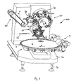
- FIG. 1 shows a packaging machine 100, which operates on the continuous principle, the articles A (see. Fig. 4 ) of a feeding and separating device 1, which is located on a horizontal U-profile frame 1 a of the machine (the latter is supported by machine feet 1 b to the ground) by a removal head 10 which is about an axis of rotation 11 ( Fig. 5 ) is rotatably received, continuously transmitted together with a piece of packaging material 12 to a packing head 20, which is also about a stationary axis of rotation 21 (FIG. Fig.
- a front rotary head 60 coaxially disposed in front of the packing head 20 is omitted for clarity, while a rear rotary head 70 is shown as part of a rotating station 80.
- the packaging machine 100 is characterized in that it only has two packaging-essential, article-carrying heads, namely the removal head 10 and the packing head 20, between finished-packed article A and the article A from the feeding and separating device 1, thereby substantially compacting the packaging process , accelerated and made more efficient.
- the delivery wheel 50 is only an auxiliary device independent of the packing operation.
- article A with working speeds of eg about 1,000 cycles per minute, ie in the high-performance area, too
- the articles A are those which consist of a ball of hard caramel or other sweetener material attached to a stem A1.
- the ball of the article A is designated A2.
- arrows K, L, M, N, O, P denote the respective directions of rotation of distributor disc 2 (arrow K), feeding ring 3 (arrow L), removal head 10 (arrow M), packing head 20 (arrow N), dispensing wheel 50 (arrow O) and conveying direction of the delivery belt 40 (arrow P).
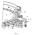
- Fig. 2 shows as a detail schematically the task and -seller 1, ie a separating disc 2, which in a known manner from its axis 2a sloping downwards outwards, along the outer periphery of the separating disc 2 astancering 3 with pockets 4 for receiving the ball A2 of the article A is provided, on whose outer circumference pass over the pockets 4 in receiving slots 5, in which, with the product position being correct, the respective handle A1 of the article A is received radially outward (cf. Fig. 4 and 5 ).
- a Farmweiser 6 on the separating disc 2 provides a brush system 7 with individually driven brushes 7b, 7c, 7d in conjunction with a coil 7a, that the pockets 4 ofassiringes 3 with the products A (Ball A2) filled and located on the article A.
- Stems by the brush system 7 and the coil 7a are folded radially outwards, so that they are received in the receiving slots 5 with radially outwardly facing stem A1 (see. 4 to 6 ).
- An outer cover 8 ensures the shielding of the separating disc 2 to the outside.
- FIG. 3 and 4 are in different perspective and schematic representation again details on the one hand of the brush system 7 ( Fig. 3 ) and an empty-cycle sensor device 9 explained below. It clarifies Fig. 3 again, the different geometries of the brushes 7b, 7c, 7d, wherein the brush 7b forms a substantially elongated cylindrical body, with a first cylindrical portion 7b1, and a leading conical portion 7b2 with increasing diameter, for sorting the article A with the balls A2 in the pockets 4, which also participates in this function, the cylindrical brush 7c.
- the disk-shaped, in its width about the width ofoptionringes 3 corresponding brush 7c is used again for secure fixing of the products A (in Fig. 3 not shown) in the pockets 4. Small three-phase motors 13 individually drive each of the brushes 7b, 7c, 7d.
- Upstream of a removal position for the article A is an empty cycle sensor device 9, which scans in the present embodiment by means of a forked light barrier 15, the stems A1 of Article A, wherein downstream of the removal position a blower (blower nozzle) 16 is for articles that without Stem (so only as a ball) are in one of the pockets 4 and can not be processed.
- a blower (blower nozzle) 16 is for articles that without Stem (so only as a ball) are in one of the pockets 4 and can not be processed.
- the rail 14 are not provided so that the articles can fall freely down into a corresponding collection container.
- the gravitational force for product removal would not be sufficient, so that forcible ejection with defective articles without stem is provided by the blower 16.
- a packaging means feed device is stopped, so that in this case no piece of packaging material 12 in the Removal head 10 is guided, since then no article A is at the corresponding point of the removal head 10.
- a positioning bracket 17 provided above the charging ring 3 and in the area above the stems A1 likewise serves for the correct positioning of the articles A and thus the positioning security. In view of the high working speeds, the most error-free orientation of the separated articles A is important.
- brush system 7 for the reliable placement of the article A in the pockets 4 and thus to ensure a high degree of filling the mindfulringes 3 may also consist of a single mold brush having a correspondingly adapted geometry in individual sections to the here on three brushes 7b, 7c, 7d split placement function to ensure.
- Fig. 5 shows in a schematic and perspective partial representation of the article recording situation and the removal head 10 at the sampling point at which the article A are removed from the innovationring 3. Its direction of rotation is indicated by the arrow L, while the direction of rotation of the removal head 10 rotating about the axis of rotation 11 is designated by the arrow M.
- the articles A positioned in the feed ring 3 are placed on the stem A1 at an in Fig. 5 taken with E withdrawal point, wherein the removal head 10 rotates in the same direction to the direction of rotation of innovationringes 3 about the stationary axis of rotation 11.
- On its front are removal units 18, which in turn are pivotally mounted about a respective pivot axis 19 on the removal head 10.
- the removal head 10 is provided with six arranged in the circumferential direction at a uniform angular distance, pivotable removal units 18 (s. Fig. 6 ), wherein each removal unit 18 is associated with an additional and about a parallel pivot axis 22 pivotable packaging tongs 23, as shown in Fig. 6 and 7 can be seen in more detail.
- Each removal unit 18 consists of a holding jaw pair 24 with a front in the direction of rotation of the removal head, front holding jaw 24a and a lying in the direction of rotation of the removal head 10, rear holding jaw 24b.
- the holding jaws 24a, 24b of each holding jaw pair 24 are each arranged on the common pivot axis 19, around which they perform on the one hand an opening and closing movement for detecting and holding the handle A1 of the article A, as to this pivot axis 19 and the total holding jaw pair 24 relative to the rotational movement of the Removal head 10 is pivotable about the axis of rotation 11.
- the holding jaws 24a and 24b have, as clearly in the Fig. 5 and 6 shown, on their inner surfaces prismatic surfaces Z on, for safe and reliable gripping the respective cylindrical stem A1 of the article A. Moreover, contributes a large opening width of the holding jaw pairs 24 in addition to the prism shape to securely hold the stems A1, lead and thus to ensure extremely reliable product handling without relying on other management bodies.
- pivotable removal units 18 may be provided on the removal head 10.
- this removal head 10 In addition to the detection of the article A on the stems A1 in an upper end, ie in the greatest possible proximity to the ball A2 is another feature of this removal head 10 in that it also has packaging tweezers 23, ie not only the product removal from the task and separation device. 1 (singling disc 2), but the removal means 10, the packaging material, ie the packaging material pieces 12 are discretely supplied from a packaging material supply device, not shown here, and thus the functions "removal" and "packaging material supply to the article” are effected in one head.
- This is in Fig. 7 clarifies and leads to a significant increase in efficiency and a compression of the packaging functions and therefore allows to penetrate into new performance areas for the packaging of such articles, which have a stem.
- Packffenzange 23 performs an accelerated movement and serves to create the possibility already between sampling point onsimilarring 3 and transfer point to the packing head 20 the packaging material required for the packaging of the item A 12 to the removal head 10 and this on the article A in conjunction to arrange with the holder of the same by the holding jaw pair 24.
- the removal head 10 is in "rolling engagement" with the packing head 20, which has in a comparable manner and number of packs 36, each of a relative to a rotation axis pivotable packing head holding jaw pairs 37, each associated with a separately pivotally mounted inner folder 38 , To carry out the wrapping and wrapping of the article A by a packaging tube, as will be explained below.
- the holding jaw pairs 24 of the same can still one Be rotatable in a radial plane extending vertical axis, if a reorientation of the position of the product, for example, by 90 °, before the supply of the piece of packaging material is necessary or useful. That is, the removal head can also additionally serve for a position reorientation of the article between withdrawal position of charging ring 3 and a transfer position on the packing head 20.
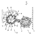
- Fig. 8 schematically shows the interaction between the extraction head 10 and packing head 20 and illustrates the processes that take place respectively within the heads 10, 20.
- Fig. 8 Prior to transfer of the article A with the packaging material piece 12 to a packing head holding jaw pair 37 with the packing head holding jaws 37a and 37b, the piece of packaging material is placed in an angular or U-shape around the article (ie around the ball A2 thereof) Fig. 8 clarified (see also Fig. 15 ).
- the packing head holding jaws 37a, 37b of a packing head holding jaw pair 37 grip the article A, ie in each case with the packaging material piece 12 forming a packaging tube in connection with the wrapping of the packaging material 12 by means of the inner folder 38 and an outer folding sheet 39 (see FIG. Fig. 8 ).
- the cylindrical packing tube around the ball A2 is formed by means of a pivoting movement of the inner butterfly 38 and the circumferential movement along the outer folding sheet 39, as is familiar to those skilled in the art, so that further detailed explanations appear dispensable (vlg. Fig. 11 ).
- the article A (Lollipop) on the one hand (above) to be wrapped with a rotary wing impact, while on the opposite side (on the stem A1) is a clean screwing and sealing the packaging material to the stem A1 for a consumer-friendly product is essential. Therefore, the packing head 20 is part of a rotating station 80 having a front turret 60 and a rear turret 70, as shown in FIG Fig. 13 is illustrated in a side view. For reasons of clarity, in particular the front rotary head 60 in the other representations, with the exception of Fig. 10 Not shown.
- Each of the front and rear turrets 60, 70 carries a number of rotary grippers 61, 71 corresponding to the packing units 36, which rotate synchronously with the rotation of the packing head 20 about the rotation axis 21, so that the relative position of the packing head holding jaw pairs 37 to the rotary grippers 61 , 71 with corresponding rotary gripper jaw pairs 62, 72 remains unchanged.
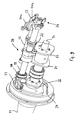
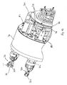
- Fig. 10 shows again in a perspective sectional view of the essential components of the packaging machine according to the present embodiment with the task and separation device 1 with theoptionring 3 and the product pockets 4, the removal head 10 with the removal units 18 including the packaging tongs 23 and the packing head 20 with the packing head Holding jaw pairs 37 and the front rotary head 60, the rear rotary head 70 with the heated rotary grippers 71 and the delivery belt 40th
- the rotary gripper 71 of the rear rotary head 70 are completely different from the rotary grippers 61 of the front rotary head 60, the latter in this case of conventional construction, as in connection with a packaging material hose opposite to the stem of the product engaged and for the formation of a Rotary vane provided in a conventional manner.
- a rotary gripper 71 used ie one of the number of packing head holding jaw pairs 37 corresponding and synchronous with these rotating number of rotary grippers 71 which are arranged on the rear rotary head 70 and in turn about a longitudinal axis 75 relative to the rotary head 70 are rotatable.
- the rotary gripper 71 with a relation to the rotational speed of the rotary head 70 higher rotational speed of this means each one mounted in the rotary head 70 rotary gripper shaft 75a about its longitudinal axis 75 rotate evenly.
- the rotary grippers 71 have Wheelgreiferbackencrue 72 with a rotary gripper jaw 72a and a rotary gripper jaw 72b, which perform an opening and closing movement about a longitudinal axis 75 orthogonal axis F (pivotal movement).
- a receiving recess 73 is provided, measured taking into account a diameter of the stem A1, which is received therein to screw the packaging tube end between stem A1 and rotary gripper 71 and smoothly seal to the stem A1, wherein the rotary gripper 71 about its longitudinal axis 75 the perform predicted rotational movement relative to the rotary head 70.
- the rotary gripper jaws 72a, 72b are offset relative to their storage section about the axis F by about 90 °, so that the stem A1 of the products can be consistently smooth and embraced with appropriate game for sealing the packaging material.
- the rotary grippers 71 are distinguished from the rotary grippers 61 on the front rotary head 60 in that they are heated, and by heating the rotary gripper 31 or at least one of the rotary gripper jaws 72a, 72b can be a heat sealing and in conjunction with appropriate packing material a high Ansiegel27 on Stalk be realized in the area of the transition from the stem A1 to the ball A2.
- FIG. 12 Like the partial perspective view of the rear turret 70 according to FIG Fig. 12 illustrates the heating of the rotary gripper 71 or one or both rotary gripper jaws 72a, 72b each of the rotary gripper 71 (here always both rotary gripper jaws 72a, 72b heated) with the help of in the rotary gripper jaws 72a, 72b used heating cartridges (not shown here), if necessary But can also be used in the rotary gripper jaws 72a, 72b Schublättchen. The heating can also be carried out inductively or by laser or Elektronenstrahlbeetzschung.
- the power supply to the rotary grippers 71 of the rear rotary head 70 takes place taking into account the required rotational movement of the rotary gripper 71 about its longitudinal axis 75 (parallel axis to the axis of rotation 21 of the packing head 20 and des rear turret 70) via a first slip ring system 74 with slip rings 76 fixed to the housing and contact brushes 77 carried on the turret 70, and a second turret 70, not shown here and within the rotary turret sleeves 81 (respectively connected to the turret shafts 75a, ie rotate the rotational speed of the rotary grippers 71) arranged slip ring system, taking into account the rotation of the rotary gripper 71 about its longitudinal axis 75th
- a preferably non-contact temperature measurement (infrared temperature measurement) is provided which is part of a control circuit for controlling the heating power to the rotary gripper jaw pairs.
- a control circuit for controlling the heating power to the rotary gripper jaw pairs.
- the temperature monitoring or measurement could also be done directly via temperature sensor in the heated parts of the rotary gripper 71.
- the application of heated rotary grippers 71 is not limited to the present embodiment or stemmed products, but is also suitable for other applications, e.g. in the manufacture of rotary wing packaging or packaging in double-twist or single-twist (bag folding, Bunch folding), especially when using relatively strong or high return force having packaging materials.
- the dispenser which conveys the finished packaged articles (lollipops) to a delivery belt 40 via a delivery wheel 50 is shown schematically in FIG Fig. 1 shown.
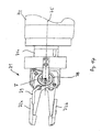
- Fig. 14 shows the heated rotary gripper 71 schematically with the rotary gripper jaws 72a and 72b, a spirally wound to compensate for movement power supply line 78 and a line section 79 to the in Fig. 14 upper rotary gripper jaw 72a in which the heating cartridge is located.
- the power supply line 78 is electrically conductively connected to the second slip ring system within the rotary rotary gripper sleeve 81. It goes without saying that the first slip ring system 77 is conductively connected to the second slip ring system. An envelope of the line section 79 is grounded connected to the housing.
- Fig. 15 is shown schematically the product flow and the positional orientation of the article A in connection with the supply of a packaging.
- the upper packaging material supply 110 and the lower packaging material supply 120 are provided for automatic packaging change.
- the products A arrive from the separating device 1 via the removal head 10, into which the packaging material piece 12 is injected for transfer to the packing head 20, in which the product A is wrapped with a stem (Lollipop) and screwed on the one hand and sealed on the stem A1, on the other hand a rotary wing is closed.
- a circulation of about 270 ° of the finished packaged article is delivered from the packing head 20 to the dispensing wheel 50, which deposits the finished packaged article on the delivery belt 40 for removal from the machine.
- a continuously operating packaging machine is proposed for the first time, which has only two packaging-essential, product-carrying heads, the removal head and the packing head and the removal head is provided with additional functional organs for supplying packaging.
- the invention is not limited to the packaging of confectionery with stem, but it can be done with appropriate adaptation of the principles set out above in a similar manner, the packaging of other small-sized items in other types of folding.
- packing items with a handle it is possible by gripping the items on a stick in a handle section
- close to the actual product (ball) it was possible to practically eliminate the influence of errors and tolerances resulting from product production (attachment of the stem to the ball) in their influence on the further packaging process.
- the use of heated rotary grippers enables not only a clean sealing of packaging material on a stick, but in principle an improvement in the manufacture of packages with rotary blades.
- a packaging machine has a compact, compact structure and is characterized by a for complicated products, such as products with stem, previously unattained packaging performance in a range of 600 to 1000 strokes per minute, at the same time dynamic quiet running, the latter, in particular because of the continuous working principle.
- the invention provides, for the first time, a continuous product packaging machine with two product-processing heads, which makes it possible, in the case of complicated products (products with handle), in previously unachievable performance ranges of e.g. Approximately 1000 work cycles per minute to penetrate, while a compact and product and packaging sparing structure to realize, combined with high product safety and low susceptibility to failure of the packaging device.
Landscapes
- Engineering & Computer Science (AREA)
- Mechanical Engineering (AREA)
- Auxiliary Devices For And Details Of Packaging Control (AREA)
Priority Applications (1)
| Application Number | Priority Date | Filing Date | Title |
|---|---|---|---|
| EP10004982.4A EP2218645B1 (fr) | 2005-04-14 | 2006-02-27 | Procédé et dispositif destinés à l'emballage d'articles de petite taille |
Applications Claiming Priority (2)
| Application Number | Priority Date | Filing Date | Title |
|---|---|---|---|
| DE200510017329 DE102005017329B4 (de) | 2005-04-14 | 2005-04-14 | Verfahren und Vorrichtung zum Verpacken kleinstückiger Artikel |
| EP20060003941 EP1712472B1 (fr) | 2005-04-14 | 2006-02-27 | Procédé et dispositif pour l'emballage de petits articles |
Related Parent Applications (2)
| Application Number | Title | Priority Date | Filing Date |
|---|---|---|---|
| EP20060003941 Division EP1712472B1 (fr) | 2005-04-14 | 2006-02-27 | Procédé et dispositif pour l'emballage de petits articles |
| EP06003941.9 Division | 2006-02-27 |
Related Child Applications (1)
| Application Number | Title | Priority Date | Filing Date |
|---|---|---|---|
| EP10004982.4A Division EP2218645B1 (fr) | 2005-04-14 | 2006-02-27 | Procédé et dispositif destinés à l'emballage d'articles de petite taille |
Publications (3)
| Publication Number | Publication Date |
|---|---|
| EP1939092A2 true EP1939092A2 (fr) | 2008-07-02 |
| EP1939092A3 EP1939092A3 (fr) | 2008-07-09 |
| EP1939092B1 EP1939092B1 (fr) | 2010-05-12 |
Family
ID=36283903
Family Applications (5)
| Application Number | Title | Priority Date | Filing Date |
|---|---|---|---|
| EP20060003941 Revoked EP1712472B1 (fr) | 2005-04-14 | 2006-02-27 | Procédé et dispositif pour l'emballage de petits articles |
| EP08005994A Expired - Lifetime EP1939093B1 (fr) | 2005-04-14 | 2006-02-27 | Procédé et dispositif destinés à l'emballage d'articles de petite taille |
| EP10004982.4A Expired - Lifetime EP2218645B1 (fr) | 2005-04-14 | 2006-02-27 | Procédé et dispositif destinés à l'emballage d'articles de petite taille |
| EP08005993A Expired - Lifetime EP1939092B1 (fr) | 2005-04-14 | 2006-02-27 | Procédé et dispositif destinés à l'emballage d'articles de petite taille |
| EP10004445.2A Expired - Lifetime EP2210813B2 (fr) | 2005-04-14 | 2006-02-27 | Procédé et dispositif destinés à l'emballage d'articles de petite taille |
Family Applications Before (3)
| Application Number | Title | Priority Date | Filing Date |
|---|---|---|---|
| EP20060003941 Revoked EP1712472B1 (fr) | 2005-04-14 | 2006-02-27 | Procédé et dispositif pour l'emballage de petits articles |
| EP08005994A Expired - Lifetime EP1939093B1 (fr) | 2005-04-14 | 2006-02-27 | Procédé et dispositif destinés à l'emballage d'articles de petite taille |
| EP10004982.4A Expired - Lifetime EP2218645B1 (fr) | 2005-04-14 | 2006-02-27 | Procédé et dispositif destinés à l'emballage d'articles de petite taille |
Family Applications After (1)
| Application Number | Title | Priority Date | Filing Date |
|---|---|---|---|
| EP10004445.2A Expired - Lifetime EP2210813B2 (fr) | 2005-04-14 | 2006-02-27 | Procédé et dispositif destinés à l'emballage d'articles de petite taille |
Country Status (3)
| Country | Link |
|---|---|
| EP (5) | EP1712472B1 (fr) |
| DE (4) | DE102005017329B4 (fr) |
| ES (5) | ES2309845T3 (fr) |
Cited By (2)
| Publication number | Priority date | Publication date | Assignee | Title |
|---|---|---|---|---|
| WO2022152646A1 (fr) * | 2021-01-12 | 2022-07-21 | Gea Food Solutions Weert B.V. | Matériel de séparation servocommandé |
| TWI934998B (zh) | 2021-01-12 | 2026-08-11 | 荷蘭商Gea食品解決韋爾特公司 | 伺服驅動挑選設備 |
Families Citing this family (19)
| Publication number | Priority date | Publication date | Assignee | Title |
|---|---|---|---|---|
| ES2325090T5 (es) † | 2006-04-20 | 2013-06-12 | Cfs Weert B.V. | Máquina para la individualización de caramelos de palo |
| DE102006020517A1 (de) * | 2006-05-03 | 2007-11-08 | Robert Bosch Gmbh | Maschine zum Verpacken von kleinstückigen Süßwaren |
| DE102008018224A1 (de) | 2008-04-10 | 2009-10-15 | Theegarten-Pactec Gmbh & Co. Kg | Verfahren und Vorrichtung zur Übergabe von kleinstückigen, insbesondere mit einem Stiel versehenen Produkten an eine Längsfördereinrichtung |
| DE102008019605A1 (de) * | 2008-04-18 | 2009-10-22 | Theegarten Pactec Gmbh & Co. Kg | Verfahren zur Verpackung kleinstückiger Artikel, insbesondere von Pralinen oder Karamellen mit Schokoladenüberzug, in kontinuierlicher Arbeitsweise und Verpackungsmaschine, insbesondere zur Durchführung des Verfahrens |
| CN102219056B (zh) * | 2011-04-19 | 2012-12-26 | 北京申晨机械设备有限公司 | 一种掐尖包装机及其利用该装置进行掐尖包装的方法 |
| DE102011122542A1 (de) * | 2011-12-27 | 2013-06-27 | Theegarten-Pactec Gmbh & Co. Kg | Verpackungsmaschine zur Verpackung kleinstückiger Produkte und Vereinzelungseinrichtung |
| DE102012019909A1 (de) | 2012-10-11 | 2014-04-17 | Theegarten-Pactec Gmbh & Co. Kg | Hochleistungs-Verpackungsverfahren zur Verpackung von, insbesondere kleinstückigen, Produkten und Hochleistungs-Verpackungseinrichtung, insbesondere zur Durchführung des Verfahrens |
| DE102014005959A1 (de) | 2013-04-30 | 2014-10-30 | Theegarten-Pactec Gmbh & Co. Kg | Verfahren zur Gruppierung von Artikeln zu Artikelstangen und Gruppiereinrichtung sowie Verpackungsmaschine mit einer solchen nebst Steuereinrichtung für Produkt-Halteeinrichtungen |
| DE102013007385A1 (de) | 2013-04-30 | 2014-10-30 | Theegarten-Pactec Gmbh & Co. Kg | Steuerungseinrichtung für Produkt-Halteeinrichtungen und Verpackungsmaschine mit einer solchen |
| EP2894103B1 (fr) | 2014-01-10 | 2016-09-07 | Robert Bosch Gmbh | Procédé et dispositif d'emballage de produits alimentaires en portions individuelles |
| CN104176294A (zh) * | 2014-08-29 | 2014-12-03 | 成都三可实业有限公司 | 一种糖果内纸包装装置 |
| CN105346755B (zh) * | 2015-11-30 | 2018-11-20 | 成都三可实业有限公司 | 一种棒棒糖包装机 |
| EP3187424B1 (fr) | 2015-12-29 | 2017-12-27 | Theegarten-Pactec Gmbh & Co. Kg | Procede et dispositif destines a l'emballage d'articles de petite taille |
| DE102017206867A1 (de) | 2017-04-24 | 2018-10-25 | Theegarten-Pactec Gmbh & Co. Kg | Rotationskopf und Verfahren zum Transport von Produkten unter Verwendung desselben |
| CN109573146B (zh) * | 2018-11-30 | 2023-07-28 | 江苏飞龙食品机械有限公司 | 一种单扭鼓气包装机 |
| DE102019210354B4 (de) * | 2019-07-12 | 2024-06-06 | Theegarten-Pactec Gmbh & Co. Kg | Rotationskopf mit rotierenden Arbeitsstationen |
| CN111330923B (zh) * | 2020-03-11 | 2021-05-04 | 新昌县兴欧智能科技有限公司 | 一种双头扭结式棒糖包装设备 |
| CN113602569A (zh) * | 2021-08-10 | 2021-11-05 | 上海理工大学 | 一种用于筒制产品的全自动立式包装机 |
| CN115593699B (zh) * | 2022-12-15 | 2023-02-28 | 常州市双马医疗器材有限公司 | 一种用于注射器生产的包装设备 |
Family Cites Families (27)
| Publication number | Priority date | Publication date | Assignee | Title |
|---|---|---|---|---|
| DE606423C (de) * | 1933-03-15 | 1934-12-01 | Bruno Boerner | Maschine zum Verpacken von Massengegenstaenden |
| JPS5215030B2 (fr) * | 1971-11-09 | 1977-04-26 | ||
| JPS5326535B2 (fr) * | 1973-04-07 | 1978-08-02 | ||
| US4408435A (en) * | 1980-02-14 | 1983-10-11 | Baker Perkins Holdings Limited | Wrapping machines |
| EP0036282A1 (fr) * | 1980-03-13 | 1981-09-23 | Wm. Wrigley Jr. Company | Machine à envelopper des objets |
| EP0064575B1 (fr) * | 1981-05-13 | 1985-08-07 | Henricus Antonius Jacobus Maria Derckx | Dispositif pour tordre les bords d'emballages |
| DD210656A1 (de) † | 1982-09-30 | 1984-06-20 | Nagema Veb K | Vorrichtung zum einwickeln von bonbons |
| DD249681A1 (de) * | 1986-06-04 | 1987-09-16 | Nagema Veb K | Vorrichtung zum uebergeben von bonbons |
| IT1234027B (it) * | 1989-03-14 | 1992-04-24 | Gd Spa | Macchina incartatrice continua |
| DE4314142C1 (de) * | 1993-05-01 | 1994-07-28 | Pactec Dresden Gmbh | Einrichtung zum Falten einer Packmittelhülle für die Säckchen- oder Körbchenfaltung |
| US5450706A (en) * | 1993-05-24 | 1995-09-19 | Latini Machine Company, Inc. | Single twist bunch wrapping machine |
| NL9402167A (nl) * | 1994-12-20 | 1996-08-01 | Derckx Henricus A J M | Inrichting voor het verpakken van een lollie. |
| DE19502562A1 (de) † | 1995-01-27 | 1996-08-01 | Pactec Verpackungsmaschinen Fa | Verfahren und Einrichtung zum Einhüllen von Gütern in plastisch verformbares, folienartiges Verpackungsmaterial |
| DE19618510A1 (de) † | 1996-05-08 | 1997-11-13 | Pactec Verpackungsmaschinen Fa | Rotations-Transportvorrichtung zur Weitergabe von Gegenständen |
| DE19642014B4 (de) † | 1996-10-11 | 2005-08-04 | Pactec Verpackungsmaschinen-Fabrik Theegarten Gmbh & Co. Kg | Vorrichtung zum Verpacken kleinstückiger Artikel im Falteinschlag |
| DE19715949A1 (de) † | 1997-04-16 | 1998-10-22 | Pactec Verpackungsmaschinen Fa | Verfahren zur Vereinzelung von kleinformatigen Gegenständen und Vereinzelungsvorrichtung |
| WO2000021835A1 (fr) * | 1998-10-15 | 2000-04-20 | Carugil, S.L. | Machine a emballer les sucettes |
| DE19920710B4 (de) * | 1999-05-05 | 2010-07-01 | Theegarten-Pactec Gmbh & Co. Kg | Vorrichtung zur Verpackung kleinstückiger Artikel |
| US6539687B1 (en) * | 2000-07-13 | 2003-04-01 | Mars, Incorporated | Modular wrapping apparatus |
| ITMI20011736A1 (it) * | 2001-08-07 | 2003-02-07 | Eurosicma S P A | Macchina di alimentazione ordinata di prodotti dolciari |
| BR0309351B1 (pt) * | 2002-04-18 | 2012-09-18 | máquina para embalar produtos. | |
| DE10217898A1 (de) † | 2002-04-22 | 2003-11-06 | Theegarten Pactec Gmbh & Co Kg | Einrichtung und Verfahren zum Vereinzeln kleinstückiger Artikel |
| DE10217892A1 (de) * | 2002-04-22 | 2003-11-06 | Theegarten Pactec Gmbh & Co Kg | Einrichtung und Verfahren zum Zuführen von Packstoffmaterial |
| NL1023733C2 (nl) * | 2003-06-24 | 2004-12-28 | C F S Weert B V | Verpakkingsmachine. |
| NL1028314C2 (nl) * | 2004-07-26 | 2006-04-04 | Cfs Weert Bv | Lollie en inrichting voor vervaardiging daarvan. |
| NL1026777C2 (nl) * | 2004-08-04 | 2006-02-13 | Cfs Weert Bv | Verpakkingsmachine voor lollies. |
| NL1026780C2 (nl) * | 2004-08-04 | 2006-02-13 | Cfs Weert Bv | Overbrenginrichting voor lollies. |
-
2005
- 2005-04-14 DE DE200510017329 patent/DE102005017329B4/de not_active Expired - Fee Related
-
2006
- 2006-02-27 ES ES06003941T patent/ES2309845T3/es not_active Expired - Lifetime
- 2006-02-27 EP EP20060003941 patent/EP1712472B1/fr not_active Revoked
- 2006-02-27 EP EP08005994A patent/EP1939093B1/fr not_active Expired - Lifetime
- 2006-02-27 ES ES10004982.4T patent/ES2695033T3/es not_active Expired - Lifetime
- 2006-02-27 EP EP10004982.4A patent/EP2218645B1/fr not_active Expired - Lifetime
- 2006-02-27 ES ES10004445.2T patent/ES2393705T5/es not_active Expired - Lifetime
- 2006-02-27 DE DE200650006868 patent/DE502006006868D1/de not_active Expired - Lifetime
- 2006-02-27 ES ES08005994T patent/ES2340635T3/es not_active Expired - Lifetime
- 2006-02-27 EP EP08005993A patent/EP1939092B1/fr not_active Expired - Lifetime
- 2006-02-27 ES ES08005993T patent/ES2341190T3/es not_active Expired - Lifetime
- 2006-02-27 DE DE200650001468 patent/DE502006001468D1/de not_active Expired - Lifetime
- 2006-02-27 EP EP10004445.2A patent/EP2210813B2/fr not_active Expired - Lifetime
- 2006-02-27 DE DE200650006945 patent/DE502006006945D1/de not_active Expired - Lifetime
Cited By (3)
| Publication number | Priority date | Publication date | Assignee | Title |
|---|---|---|---|---|
| WO2022152646A1 (fr) * | 2021-01-12 | 2022-07-21 | Gea Food Solutions Weert B.V. | Matériel de séparation servocommandé |
| CN116829483A (zh) * | 2021-01-12 | 2023-09-29 | Gea食品策划韦尔特公司 | 伺服驱动的挑选设备 |
| TWI934998B (zh) | 2021-01-12 | 2026-08-11 | 荷蘭商Gea食品解決韋爾特公司 | 伺服驅動挑選設備 |
Also Published As
| Publication number | Publication date |
|---|---|
| ES2393705T3 (es) | 2012-12-27 |
| ES2695033T3 (es) | 2018-12-28 |
| EP1939093B1 (fr) | 2010-04-28 |
| ES2340635T3 (es) | 2010-06-07 |
| DE502006006945D1 (de) | 2010-06-24 |
| EP2210813B2 (fr) | 2017-03-08 |
| EP1939093A3 (fr) | 2008-07-09 |
| DE102005017329A1 (de) | 2006-10-19 |
| EP1939092A3 (fr) | 2008-07-09 |
| EP2218645A1 (fr) | 2010-08-18 |
| ES2309845T3 (es) | 2008-12-16 |
| EP2218645B1 (fr) | 2018-10-31 |
| EP2210813A1 (fr) | 2010-07-28 |
| ES2341190T3 (es) | 2010-06-16 |
| DE502006001468D1 (de) | 2008-10-16 |
| ES2393705T5 (es) | 2017-07-31 |
| EP1712472A1 (fr) | 2006-10-18 |
| EP1939092B1 (fr) | 2010-05-12 |
| EP1939093A2 (fr) | 2008-07-02 |
| EP1712472B1 (fr) | 2008-09-03 |
| DE102005017329B4 (de) | 2014-10-16 |
| DE502006006868D1 (de) | 2010-06-10 |
| EP2210813B1 (fr) | 2012-11-14 |
Similar Documents
| Publication | Publication Date | Title |
|---|---|---|
| EP2218645B1 (fr) | Procédé et dispositif destinés à l'emballage d'articles de petite taille | |
| EP0034377B2 (fr) | Procédé et dispositif pour amener des objets, notamment des paquets, dans le trajet de circulation d'un convoyeur sans fin | |
| EP0275481B1 (fr) | Procédé et dispositif pour emballer des mouchoirs en papier | |
| DE2526047A1 (de) | Umlaufende foerdervorrichtung an einer einwickelmaschine | |
| DE102014005959A1 (de) | Verfahren zur Gruppierung von Artikeln zu Artikelstangen und Gruppiereinrichtung sowie Verpackungsmaschine mit einer solchen nebst Steuereinrichtung für Produkt-Halteeinrichtungen | |
| DE3545884A1 (de) | Vorrichtung zum herstellen von (zigaretten-) packungen aus mindestens einem faltbaren zuschnitt | |
| EP2108589B1 (fr) | Procédé et dispositif de transfert de produits en petites pièces, notamment dotés d'un manche, sur un dispositif de transport longitudinal | |
| DE2254659C3 (de) | Bonboneinwickelmaschine | |
| EP0304736B1 (fr) | Procédé et dispositif pour envelopper spécialement des paquets de cigarettes | |
| WO2009127418A2 (fr) | Procédé d'emballage d'articles en petits morceaux, en particulier de pralines ou de caramels avec enrobage de chocolat, en marche continue, et machine à emballer, en particulier pour la mise en œuvre du procédé | |
| EP0806358B1 (fr) | Méthode et dispositif de transfert d'articles | |
| DE2849853A1 (de) | Vorrichtung zum kontinuierlichen einwickeln von bonbons | |
| DE3915888C2 (de) | Vorrichtung zum Übergeben von Bonbons | |
| EP0143961A1 (fr) | Dispositif pour l'enveloppement d'objets, spécialement de groupes de cigarettes | |
| DE2454743A1 (de) | Vorrichtung fuer verpackungsmaschinen, um die huelle von bonbons u.dgl. in der verpackungsform mit einem (koerbchen) oder zwei sogenannten zipfeln zu gestalten | |
| DE69606131T2 (de) | Kontinuierliches Verfahren zum Umhüllen von Gegenständen | |
| DE202005021491U9 (de) | Verpackungsmaschine | |
| DE2934834C2 (de) | Vorrichtung zur Herstellung von Stangenpackungen aus vorzugsweise einzeln eingewickelten Bonbons o.ä. Süßwarenstücken. | |
| DE2329534A1 (de) | Vorrichtung zum einwickeln von bonbons oder aehnlichen kleinteilen | |
| EP0806385A1 (fr) | Méthode et dispositif de transfert pour délivrer des groupes d'objets d'un transporteur à bande d'empilage | |
| EP0835831A1 (fr) | Dispositif de transport rotatif pour le transfert d'articles | |
| EP0915017A1 (fr) | Procédé et dispositif pour emballer des petits objets, en particulier des produits de confiserie | |
| EP1016594A2 (fr) | Procédé et dispositif pour emballer des articles individuels en piles contenant plusieurs articles individuels | |
| EP0367041B1 (fr) | Dispositif pour transférer des objets parallélépipèdiques | |
| DE19860863A1 (de) | Verfahren und Einrichtung zur Verpackung von Einzelstücken zu mehrere Einzelstücke enthaltende Stangen |
Legal Events
| Date | Code | Title | Description |
|---|---|---|---|
| PUAI | Public reference made under article 153(3) epc to a published international application that has entered the european phase |
Free format text: ORIGINAL CODE: 0009012 |
|
| PUAL | Search report despatched |
Free format text: ORIGINAL CODE: 0009013 |
|
| AC | Divisional application: reference to earlier application |
Ref document number: 1712472 Country of ref document: EP Kind code of ref document: P |
|
| AK | Designated contracting states |
Kind code of ref document: A2 Designated state(s): AT BE BG CH CY CZ DE DK EE ES FI FR GB GR HU IE IS IT LI LT LU LV MC NL PL PT RO SE SI SK TR |
|
| AX | Request for extension of the european patent |
Extension state: AL BA HR MK RS |
|
| AK | Designated contracting states |
Kind code of ref document: A3 Designated state(s): AT BE BG CH CY CZ DE DK EE ES FI FR GB GR HU IE IS IT LI LT LU LV MC NL PL PT RO SE SI SK TR |
|
| AX | Request for extension of the european patent |
Extension state: AL BA HR MK RS |
|
| 17P | Request for examination filed |
Effective date: 20080825 |
|
| 17Q | First examination report despatched |
Effective date: 20081106 |
|
| AKX | Designation fees paid |
Designated state(s): CH DE ES GB IT LI NL |
|
| GRAP | Despatch of communication of intention to grant a patent |
Free format text: ORIGINAL CODE: EPIDOSNIGR1 |
|
| GRAS | Grant fee paid |
Free format text: ORIGINAL CODE: EPIDOSNIGR3 |
|
| GRAA | (expected) grant |
Free format text: ORIGINAL CODE: 0009210 |
|
| AC | Divisional application: reference to earlier application |
Ref document number: 1712472 Country of ref document: EP Kind code of ref document: P |
|
| AK | Designated contracting states |
Kind code of ref document: B1 Designated state(s): CH DE ES GB IT LI NL |
|
| REG | Reference to a national code |
Ref country code: GB Ref legal event code: FG4D Free format text: NOT ENGLISH |
|
| REG | Reference to a national code |
Ref country code: CH Ref legal event code: EP |
|
| REG | Reference to a national code |
Ref country code: CH Ref legal event code: NV Representative=s name: REUTELER & CIE S.A. |
|
| REG | Reference to a national code |
Ref country code: ES Ref legal event code: FG2A Ref document number: 2341190 Country of ref document: ES Kind code of ref document: T3 |
|
| REF | Corresponds to: |
Ref document number: 502006006945 Country of ref document: DE Date of ref document: 20100624 Kind code of ref document: P |
|
| REG | Reference to a national code |
Ref country code: NL Ref legal event code: T3 |
|
| PLBE | No opposition filed within time limit |
Free format text: ORIGINAL CODE: 0009261 |
|
| STAA | Information on the status of an ep patent application or granted ep patent |
Free format text: STATUS: NO OPPOSITION FILED WITHIN TIME LIMIT |
|
| 26N | No opposition filed |
Effective date: 20110215 |
|
| REG | Reference to a national code |
Ref country code: DE Ref legal event code: R097 Ref document number: 502006006945 Country of ref document: DE Effective date: 20110214 |
|
| PGFP | Annual fee paid to national office [announced via postgrant information from national office to epo] |
Ref country code: ES Payment date: 20200309 Year of fee payment: 15 Ref country code: IT Payment date: 20200228 Year of fee payment: 15 Ref country code: DE Payment date: 20200227 Year of fee payment: 15 Ref country code: NL Payment date: 20200221 Year of fee payment: 15 Ref country code: GB Payment date: 20200221 Year of fee payment: 15 |
|
| PGFP | Annual fee paid to national office [announced via postgrant information from national office to epo] |
Ref country code: CH Payment date: 20200221 Year of fee payment: 15 |
|
| REG | Reference to a national code |
Ref country code: DE Ref legal event code: R119 Ref document number: 502006006945 Country of ref document: DE |
|
| GBPC | Gb: european patent ceased through non-payment of renewal fee |
Effective date: 20210227 |
|
| PG25 | Lapsed in a contracting state [announced via postgrant information from national office to epo] |
Ref country code: LI Free format text: LAPSE BECAUSE OF NON-PAYMENT OF DUE FEES Effective date: 20210228 Ref country code: CH Free format text: LAPSE BECAUSE OF NON-PAYMENT OF DUE FEES Effective date: 20210228 |
|
| REG | Reference to a national code |
Ref country code: NL Ref legal event code: MM Effective date: 20210301 |
|
| PG25 | Lapsed in a contracting state [announced via postgrant information from national office to epo] |
Ref country code: NL Free format text: LAPSE BECAUSE OF NON-PAYMENT OF DUE FEES Effective date: 20210301 |
|
| PG25 | Lapsed in a contracting state [announced via postgrant information from national office to epo] |
Ref country code: DE Free format text: LAPSE BECAUSE OF NON-PAYMENT OF DUE FEES Effective date: 20210901 Ref country code: GB Free format text: LAPSE BECAUSE OF NON-PAYMENT OF DUE FEES Effective date: 20210227 |
|
| PG25 | Lapsed in a contracting state [announced via postgrant information from national office to epo] |
Ref country code: IT Free format text: LAPSE BECAUSE OF NON-PAYMENT OF DUE FEES Effective date: 20210227 |
|
| REG | Reference to a national code |
Ref country code: ES Ref legal event code: FD2A Effective date: 20220517 |
|
| PG25 | Lapsed in a contracting state [announced via postgrant information from national office to epo] |
Ref country code: ES Free format text: LAPSE BECAUSE OF NON-PAYMENT OF DUE FEES Effective date: 20210228 |