EP2246461B1 - Vorrichtung zum schwebezonenschmelzen - Google Patents
Vorrichtung zum schwebezonenschmelzen Download PDFInfo
- Publication number
- EP2246461B1 EP2246461B1 EP08864615A EP08864615A EP2246461B1 EP 2246461 B1 EP2246461 B1 EP 2246461B1 EP 08864615 A EP08864615 A EP 08864615A EP 08864615 A EP08864615 A EP 08864615A EP 2246461 B1 EP2246461 B1 EP 2246461B1
- Authority
- EP
- European Patent Office
- Prior art keywords
- sample
- infrared ray
- floating zone
- zone melting
- melting apparatus
- Prior art date
- Legal status (The legal status is an assumption and is not a legal conclusion. Google has not performed a legal analysis and makes no representation as to the accuracy of the status listed.)
- Active
Links
- 238000004857 zone melting Methods 0.000 title claims description 110
- 239000013078 crystal Substances 0.000 claims description 172
- 238000010438 heat treatment Methods 0.000 claims description 56
- 239000011364 vaporized material Substances 0.000 claims description 28
- VYPSYNLAJGMNEJ-UHFFFAOYSA-N silicon dioxide Inorganic materials O=[Si]=O VYPSYNLAJGMNEJ-UHFFFAOYSA-N 0.000 claims description 21
- 239000010453 quartz Substances 0.000 claims description 20
- 230000007246 mechanism Effects 0.000 claims description 19
- 230000008018 melting Effects 0.000 claims description 19
- 238000002844 melting Methods 0.000 claims description 19
- 229910052736 halogen Inorganic materials 0.000 description 19
- 150000002367 halogens Chemical class 0.000 description 19
- 238000000034 method Methods 0.000 description 15
- 239000007791 liquid phase Substances 0.000 description 14
- 239000007790 solid phase Substances 0.000 description 14
- 239000000463 material Substances 0.000 description 13
- 238000004090 dissolution Methods 0.000 description 10
- 230000000694 effects Effects 0.000 description 10
- 239000000203 mixture Substances 0.000 description 8
- 210000003625 skull Anatomy 0.000 description 6
- 239000000126 substance Substances 0.000 description 6
- 239000012768 molten material Substances 0.000 description 5
- BASFCYQUMIYNBI-UHFFFAOYSA-N platinum Chemical compound [Pt] BASFCYQUMIYNBI-UHFFFAOYSA-N 0.000 description 4
- 230000008021 deposition Effects 0.000 description 3
- 238000010586 diagram Methods 0.000 description 3
- 238000004519 manufacturing process Methods 0.000 description 3
- 238000010521 absorption reaction Methods 0.000 description 2
- 238000007792 addition Methods 0.000 description 2
- 239000012141 concentrate Substances 0.000 description 2
- 238000011109 contamination Methods 0.000 description 2
- 238000009826 distribution Methods 0.000 description 2
- 238000012986 modification Methods 0.000 description 2
- 230000004048 modification Effects 0.000 description 2
- 230000003287 optical effect Effects 0.000 description 2
- 239000007787 solid Substances 0.000 description 2
- 239000002699 waste material Substances 0.000 description 2
- 229910052724 xenon Inorganic materials 0.000 description 2
- FHNFHKCVQCLJFQ-UHFFFAOYSA-N xenon atom Chemical compound [Xe] FHNFHKCVQCLJFQ-UHFFFAOYSA-N 0.000 description 2
- 238000009825 accumulation Methods 0.000 description 1
- 239000000654 additive Substances 0.000 description 1
- 230000000996 additive effect Effects 0.000 description 1
- PNEYBMLMFCGWSK-UHFFFAOYSA-N aluminium oxide Inorganic materials [O-2].[O-2].[O-2].[Al+3].[Al+3] PNEYBMLMFCGWSK-UHFFFAOYSA-N 0.000 description 1
- 230000000052 comparative effect Effects 0.000 description 1
- 238000007796 conventional method Methods 0.000 description 1
- 238000001514 detection method Methods 0.000 description 1
- KZHJGOXRZJKJNY-UHFFFAOYSA-N dioxosilane;oxo(oxoalumanyloxy)alumane Chemical compound O=[Si]=O.O=[Si]=O.O=[Al]O[Al]=O.O=[Al]O[Al]=O.O=[Al]O[Al]=O KZHJGOXRZJKJNY-UHFFFAOYSA-N 0.000 description 1
- 230000007613 environmental effect Effects 0.000 description 1
- 239000010419 fine particle Substances 0.000 description 1
- 239000012535 impurity Substances 0.000 description 1
- 229910052741 iridium Inorganic materials 0.000 description 1
- GKOZUEZYRPOHIO-UHFFFAOYSA-N iridium atom Chemical compound [Ir] GKOZUEZYRPOHIO-UHFFFAOYSA-N 0.000 description 1
- 230000001678 irradiating effect Effects 0.000 description 1
- 229910052863 mullite Inorganic materials 0.000 description 1
- 229910000510 noble metal Inorganic materials 0.000 description 1
- 229910052697 platinum Inorganic materials 0.000 description 1
- 239000002994 raw material Substances 0.000 description 1
- 229910052703 rhodium Inorganic materials 0.000 description 1
- 239000010948 rhodium Substances 0.000 description 1
- MHOVAHRLVXNVSD-UHFFFAOYSA-N rhodium atom Chemical compound [Rh] MHOVAHRLVXNVSD-UHFFFAOYSA-N 0.000 description 1
- HBMJWWWQQXIZIP-UHFFFAOYSA-N silicon carbide Chemical compound [Si+]#[C-] HBMJWWWQQXIZIP-UHFFFAOYSA-N 0.000 description 1
- 229910010271 silicon carbide Inorganic materials 0.000 description 1
Images




Classifications
-
- C—CHEMISTRY; METALLURGY
- C30—CRYSTAL GROWTH
- C30B—SINGLE-CRYSTAL GROWTH; UNIDIRECTIONAL SOLIDIFICATION OF EUTECTIC MATERIAL OR UNIDIRECTIONAL DEMIXING OF EUTECTOID MATERIAL; REFINING BY ZONE-MELTING OF MATERIAL; PRODUCTION OF A HOMOGENEOUS POLYCRYSTALLINE MATERIAL WITH DEFINED STRUCTURE; SINGLE CRYSTALS OR HOMOGENEOUS POLYCRYSTALLINE MATERIAL WITH DEFINED STRUCTURE; AFTER-TREATMENT OF SINGLE CRYSTALS OR A HOMOGENEOUS POLYCRYSTALLINE MATERIAL WITH DEFINED STRUCTURE; APPARATUS THEREFOR
- C30B13/00—Single-crystal growth by zone-melting; Refining by zone-melting
- C30B13/16—Heating of the molten zone
- C30B13/22—Heating of the molten zone by irradiation or electric discharge
- C30B13/24—Heating of the molten zone by irradiation or electric discharge using electromagnetic waves
-
- Y—GENERAL TAGGING OF NEW TECHNOLOGICAL DEVELOPMENTS; GENERAL TAGGING OF CROSS-SECTIONAL TECHNOLOGIES SPANNING OVER SEVERAL SECTIONS OF THE IPC; TECHNICAL SUBJECTS COVERED BY FORMER USPC CROSS-REFERENCE ART COLLECTIONS [XRACs] AND DIGESTS
- Y10—TECHNICAL SUBJECTS COVERED BY FORMER USPC
- Y10T—TECHNICAL SUBJECTS COVERED BY FORMER US CLASSIFICATION
- Y10T117/00—Single-crystal, oriented-crystal, and epitaxy growth processes; non-coating apparatus therefor
- Y10T117/10—Apparatus
- Y10T117/1024—Apparatus for crystallization from liquid or supercritical state
Definitions
- the present invention relates to a floating zone melting apparatus of the infrared concentration heating type in which a part of a sample in a rod shape for instance is irradiated with an infrared ray to heat and melt the sample, and the molten sample is solidified on a seed crystal or the like to grow a single crystal in a rod shape.
- an infrared lamp unit is prepared in which an infrared lamp such as a halogen lamp and a xenon lamp is disposed at one focal point of an ellipsoidal reflecting mirror (hereafter referred to as an elliptical mirror), infrared rays emitted from the infrared lamp unit are converged to the other focal point, a local heating of a solid sample (a sample in a rod shape for instance) that has been disposed at the location is carried out to melt and deposit the solid sample.
- the above method is called a floating zone melting method. A great number of floating zone melting apparatuses that adopt the floating zone melting method and application examples thereof have been reported.
- a sample can be molten and deposited without using a container such as a skull crucible, a contamination caused by a skull crucible material can be prevented.
- the dissolution and a deposition of a sample in a rod shape (a sample in a rod shape is also hereafter referred to as a sample rod) can be carried out in a successive manner. Consequently, a single crystal having a uniform composition can be grown from a sample rod that has been prepared to have a uniform composition by the extremely excellent method.
- a method that is almost exclusively used industrially for growing a single crystal is a pull method.
- a material is set in a skull crucible made of a noble metal such as platinum and iridium and is molten, a seed crystal is then dipped in the molten sample and is plumped, and the seed crystal is pulled up to grow a single crystal of a large size.
- the pull method is provided with disadvantages in which a skull crucible material is incorporated into a crystal as an impurity and a concentration of an additive material is not uniform.
- the floating zone melting method is provided with the following advantages and is a predominantly advantageous method industrially.
- a floating zone melting apparatus of a twin elliptical mirror type in which the above described floating zone melting method is adopted will be described in the following with reference to a conceptual diagram shown in Fig. 8 .
- an elliptical mirror 108 is disposed on the left side of a sample 102 in a rod shape and an elliptical mirror 108 is disposed on the right side of a sample 102 in a rod shape.
- Lights that are emitted from an infrared lamp 110 that has been disposed at a focal point of the elliptical mirror 108 are converged to the center point in which the second focal points thereof are shared in such a manner that the sample 102 in a rod shape is molten at the center point.
- the dissolution and a deposition of the sample 102 in a rod shape are then carried out in a successive manner to grow a single crystal.
- a numeral 106 represents a molten part and a numeral 104 represents a grown crystal.
- the parts in the front and back directions in the figure are not irradiated with lights. Consequently, in the case in which a temperature detection terminal is set to the surface of the sample 102 in a rod shape having a diameter of 10 mm for instance and a temperature distribution of a molten part of the sample 102 in a rod shape is measured without rotating the sample 102 in a rod shape, a part that is facing the infrared lamp 110 (in the right and left direction in the figure) and a part in a direction perpendicular to the right and left direction (in the front and back direction in the figure) are greatly different in a temperature. As a result, uniform dissolution and deposition are difficult disadvantageously.
- infrared lamps are set in the front and back directions of the floating zone melting apparatus 100 of a twin elliptical mirror type and total four elliptical mirrors are used to develop a new floating zone melting apparatus of a quadruple elliptical mirror type (not shown) (see Patent document 1 for instance).
- This floating zone melting apparatus is dramatically improved in a temperature distribution in a horizontal direction and enables a single crystal of a good quality to be grown as compared with the floating zone melting apparatus 100 of a twin elliptical mirror type.
- a floating zone melting apparatus 200 of an oblique quadruple elliptical mirror type has been developed in which four elliptical mirrors 108 are disposed in an oblique direction and the sample 102 in a rod shape is irradiated with an infrared ray from an oblique upper direction.
- the floating zone melting apparatus 200 of an oblique quadruple elliptical mirror type is used to carry out a growth of a single crystal as a practical matter, although it is easy to hold a large amount of molten solutions by an irradiation of an infrared ray from an oblique upper direction (to grow a single crystal having a large diameter without dropping molten solutions), it is hard to melt the sample 102 in a rod shape in many cases.
- a load of the infrared lamp 110 is extremely large in some cases.
- a temperature of a filament must be increased or a size of a filament must be increased.
- an increase in a temperature of a filament is limited, and even in the case in which a size of a filament is increased, a size of a light concentration part is enlarged, whereby an effect of increasing a temperature of molten solutions is small disadvantageously.
- the present invention was made in consideration of such conditions, and an object of the present invention is to provide a floating zone melting apparatus in which a sample rod especially having a large diameter can be stably molten with a certainty and the single crystal being grown can retain a flat shape at the interface of the solid phase and the liquid phase, whereby a single crystal having a large diameter can be grown.
- Another object of the present invention is to provide a floating zone melting apparatus in which a single crystal having a large diameter can be formed in effect by reducing a load of an infrared lamp to the greatest extent possible.
- a floating zone melting apparatus in accordance with the present invention is a floating zone melting apparatus of the infrared concentration heating type in which a sample is set in a sample chamber made of a transparent quartz tube, an atmospheric gas is introduced into the sample chamber, infrared rays emitted from a plurality of infrared ray irradiation means are converged to the sample to heat and melt the sample in this state, thereby obtaining a molten solution, and the molten solution is solidified on a seed crystal to grow a single crystal, the plurality of infrared ray irradiation means is characterized by comprising:
- infrared rays are emitted in the two directions downward from an upper side and upward from a lower side.
- a control of the interface of the solid phase and the liquid phase for a grown crystal is carried out by an irradiation of an infrared ray emitted downward from an upper side, and a sample can be efficiently molten in a stable manner by an irradiation of an infrared ray emitted upward from a lower side.
- each of the infrared ray irradiation means of the upward irradiation type disposed at the lower stage is located in each gap of the infrared ray irradiation means of the downward irradiation type disposed at regular intervals, angles between dispositions of the infrared ray irradiation means can be approximate to each other, and the total light concentration efficiency can be improved.
- a floating zone melting apparatus in accordance with the present invention may be characterized in that the infrared ray irradiation means is an infrared lamp unit comprising a rotary ellipsoidal reflecting mirror in which an inner face is used as a reflecting face and an infrared lamp disposed at one focal point thereof.
- the infrared ray irradiation means is an infrared lamp unit
- infrared rays of a required irradiation amount can be efficiently generated, and the infrared ray irradiation means can be used repeatedly by replacing an infrared lamp, whereby a production cost can be suppressed.
- a floating zone melting apparatus in accordance with the present invention may be characterized in that the infrared ray irradiation means is a laser oscillator that is configured to emit an infrared ray by a laser beam.
- the infrared ray irradiation means is a laser oscillator
- a floating zone melting apparatus in accordance with the present invention may be characterized in that the infrared ray irradiation means of the downward irradiation type and the infrared ray irradiation means of the upward irradiation type are configured to enable a position control thereof independently.
- a diameter and a growth rate of a single crystal can be adjusted by controlling a degree of heating and melting a sample.
- a shape of a single crystal that is grown can be adjusted, thereby enabling a growth of a single crystal of a good quality having a large diameter and having a shape such as a cylindrical shape and a prismatic column shape.
- a floating zone melting apparatus in accordance with the present invention may be characterized in that the infrared ray irradiation means of the downward irradiation type and the infrared ray irradiation means of the upward irradiation type are provided with an irradiation position control mechanism that is configured to independently adjust an irradiation angle and an irradiation amount of infrared rays.
- the floating zone melting apparatus is provided with a mechanism for controlling an irradiation position and an irradiation amount
- a control of a shape of the interface of the solid phase and the liquid phase for a grown crystal can be carried out while controlling a melting state corresponding to a material quality and a state of a sample, whereby a single crystal having a large diameter can be grown in a stable manner.
- a floating zone melting apparatus in accordance with the present invention may be characterized in that the infrared ray irradiation means is provided with a horizontal position control mechanism for a horizontal movement in an irradiation direction from a position in which the sample is disposed as a center.
- a focal point can be easily set to a most appropriate position corresponding to a thickness of a sample, an optical absorption property of a sample, and a degree of a diameter of a single crystal that is grown. Therefore, a single crystal can be grown in a stable manner in a most appropriate optical layout corresponding to a diameter of a single crystal.
- a floating zone melting apparatus in accordance with the present invention may be characterized in that a sample heating means in a tube shape is disposed in such a manner that a periphery of the sample is enclosed.
- a temperature of a sample rod can be maintained to be high in advance, and a single crystal can be grown in a stable manner as compared with the case in which a sample rod with a high melting point is molten by only the infrared ray irradiation means.
- the sample heating means in a tube shape absorbs the infrared ray and the infrared ray does not reach the sample.
- the present invention can suppress the above problems by the above configuration, and enables a single crystal having a high quality to be grown.
- a floating zone melting apparatus in accordance with the present invention may be characterized by further comprising a position control mechanism that is configured to control a position of the sample heating means.
- the sample heating means can be moved corresponding to a molten point of a sample rod, whereby only a desired point of a sample rod can be irradiated with an infrared ray on a constant basis to melt the sample rod.
- a floating zone melting apparatus in accordance with the present invention may be characterized in that a crystal heating means in a tube shape is disposed in such a manner that a periphery of the grown crystal is enclosed.
- an amount of heat for maintaining a temperature around the interface of the solid phase and the liquid phase of a single crystal to be high does not depend on only the infrared ray irradiation means, and a temperature around the interface of the solid phase and the liquid phase of a single crystal can be maintained to be high by compensating an amount of heat that is required for growing a single crystal with an amount of heat from the crystal heating means, whereby a single crystal having a large diameter can be grown.
- a floating zone melting apparatus in accordance with the present invention may be characterized by further comprising a position control mechanism that is configured to control a position of the crystal heating means.
- a floating zone melting apparatus in accordance with the present invention may be characterized by further comprising a mechanism in which a shielding member that is configured to limit an irradiation amount of infrared rays that are emitted from the infrared ray irradiation means is disposed around the sample and the grown crystal and in which a synchronization is enabled with a rotation and a movement of the grown crystal.
- an irradiation amount of infrared rays from a constant direction can be limited on a constant basis by rotating and moving the shielding member in synchronization with a grown crystal corresponding to an orientation of a growth of a single crystal. Consequently, a single crystal can be grown to be in a shape such as a cylindrical shape and a prismatic column shape, whereby a single crystal having a large diameter can be grown.
- a floating zone melting apparatus in accordance with the present invention may be characterized in that an introduction gas pipe made of transparent quartz that is configured to efficiently eject a vaporized material that is generated in heating and melting the sample together with the atmospheric gas outside the sample chamber is disposed between an inner wall of the sample chamber and the sample.
- the introduction gas pipe is disposed and a gap between the introduction gas pipe and a sample or a sample support part in a shaft shape can be small at a level in which a problem does not occur in a normal use, a rate of flow of the atmospheric gas that passes through the introduction gas pipe can be increased in comparison even in the case in which a supply quantity of the atmospheric gas is not increased so much.
- the introduction gas pipe is made of transparent quartz, a single crystal can be grown while a lower section of the introduction gas pipe is made to be close to a molten part without shielding infrared rays that are emitted from the infrared ray irradiation means, an effect of ejecting a vaporized material can be further improved.
- a floating zone melting apparatus in accordance with the present invention may be characterized in that a diameter of a shape of an end part that is located on the side of heating and melting the sample for the introduction gas pipe is larger than that of other parts.
- a gap between an inner diameter of the introduction gas pipe and a thickness of a sample or a sample support part in a shaft shape for supporting a sample is smaller, a rate of flow of the atmospheric gas can be increased and an effect of ejecting a vaporized material can be further improved advantageously.
- an inner diameter of the introduction gas pipe is smaller, an effect of introducing a vaporized material is smaller disadvantageously.
- vaporized materials that are generated in heating and melting a sample rod can be introduced into the introduction gas pipe and ejected outside the sample chamber by forming the introduction gas pipe in such a shape and disposing a lower section of the introduction gas pipe close to a molten part.
- an amount of a deposit substance that is stored in the sample chamber and that adheres to an inner wall of the sample chamber made of a transparent quartz pipe can be extremely small.
- a floating zone melting apparatus in accordance with the present invention may be characterized in that an atmospheric gas can be introduced in such a manner that a rate of flow of the atmospheric gas that passes through the introduction gas pipe is at least 10 cm per second.
- a vaporized material that is vaporized from a molten part in the ordinary course of events is flown to the upper side by a convection current caused by a heat and is diffused to adhere to an inner wall of an environmental transparent quartz pipe.
- the vaporized material is ejected together with the atmospheric gas outside the sample chamber.
- a floating zone melting apparatus in accordance with the present invention may be characterized by further comprising a circulation device that is configured to supply an atmospheric gas that has been ejected from the sample chamber again into the sample chamber.
- the floating zone melting apparatus is provided with a circulation device, a costly atmospheric gas can be used without a waste, whereby a cost for growing a single crystal can be suppressed.
- a floating zone melting apparatus in accordance with the present invention may be characterized in that the circulation device is configured to separate a vaporized material that is generated in heating and melting the sample and that is ejected together with the atmospheric gas by using a filter member in such a manner that only the atmospheric gas is supplied into the sample chamber.
- the vaporized material can be ejected together with the atmospheric gas outside the sample chamber, and only an atmospheric gas from which the vaporized material has been separated by using a filter member can be circulated. Consequently, an inner wall of a sample chamber made of a quartz pipe can be maintained to be clean on a constant basis, and a growth of a single crystal can be continued in a stable manner.
- a plurality of infrared ray irradiation means are disposed at two stages in such a manner that a sample is irradiated with infrared ray from two directions of an upper direction and a lower direction, and an irradiation angle and an irradiation amount of infrared rays of the infrared ray irradiation means are controlled corresponding to an actual melting property while independently controlling the infrared ray irradiation means disposed at two stages. Consequently, there can be proposed a floating zone melting apparatus in which a single crystal having a large diameter can be grown as intended by using a sample rod having a large diameter
- Fig. 1 is a schematic view showing a first embodiment of a floating zone melting apparatus in which an infrared ray irradiation means of the downward irradiation type and an infrared ray irradiation means of the upward irradiation type are used in accordance with of the present invention.
- an infrared lamp unit is used as the infrared ray irradiation means.
- a part of a sample in a rod shape for instance is irradiated with an infrared ray to heat and melt the sample, and the molten sample is solidified on a seed crystal or the like to grow a single crystal in a rod shape.
- the "downward” of the downward irradiation type that is used in the present specification indicates the range of 0° to 90° on the basis of the horizontal line.
- the “upward” of the upward irradiation type that is used in the present specification indicates the range of 0° to -90° on the basis of the horizontal line.
- seed crystal that is used in the present specification indicates a first mode of a crystal in the case in which a single crystal having a large diameter is grown by using a floating zone melting apparatus.
- grown crystal that is used in the present specification indicates a single crystal that is being grown.
- a sample rod 12 is disposed in a sample chamber 30 made of a transparent quartz tube, an atmospheric gas 32 is introduced into the sample chamber 30, infrared rays emitted from a plurality of infrared lamp units 21 are converged to the sample rod 12 to heat and melt the sample rod 12 in this state, thereby obtaining a molten solution, and the molten solution is solidified on a seed crystal to grow a single crystal.
- the plurality of infrared lamp units 21 are composed of a rotary ellipsoidal reflecting mirror 18 (hereafter referred to as an elliptical mirror 18) and an infrared lamp 20, and the plurality of infrared lamp units 21 are disposed in such a manner that a periphery of the sample rod 12 is enclosed.
- the infrared lamp units 21 share the focal point thereof with each other at the center position in which the sample rod 12 is disposed.
- the infrared lamp 20 is disposed at a focal point on the side opposite to a light concentration side of each of the elliptical mirrors 18 of the infrared lamp units 21. Infrared rays that have been emitted from the filament of the infrared lamp 20 are reflected from the elliptical mirrors 18 and converged to the other focal point to heat the sample rod 12.
- An infrared lamp such as a halogen lamp and a xenon lamp can be used as the infrared lamp 20.
- the plurality of infrared lamp units 21 that are configured as described above are composed of an infrared lamp unit 21a of the downward irradiation type that is disposed in such a manner that a straight line from one focal point to the other focal point is slanted downward and an infrared lamp unit 21b of the upward irradiation type that is disposed in such a manner that a straight line from one focal point to the other focal point is slanted upward.
- the infrared lamp unit 21a of the downward irradiation type is disposed in such a manner that the sample rod 12 is irradiated from an oblique upper direction with an infrared ray that has been reflected from the reflecting surface of the elliptical mirrors 18. It is preferable that the number of the infrared lamp units 21a of the downward irradiation type that are disposed is at least four. However, the number of the infrared lamp units 21a is not restricted in particular, and modifications can be made as needed.
- the infrared lamp unit 21b of the upward irradiation type is disposed in such a manner that the sample rod 12 is irradiated from an oblique lower direction with an infrared ray that has been reflected from the reflecting surface of the elliptical mirrors 18. It is also preferable that the number of the infrared lamp units 21b of the upward irradiation type that are disposed is at least four. However, the number of the infrared lamp units 21b is not restricted in particular.
- the infrared lamp unit 21a of the downward irradiation type and the infrared lamp unit 21b of the upward irradiation type are disposed at regular intervals around an axis of the sample rod 12 as a center.
- four infrared lamp units 21a are disposed at a regular interval of 90 degrees
- four infrared lamp units 21b are disposed at a regular interval of 90 degrees.
- the infrared lamp unit 21a of the downward irradiation type and the infrared lamp unit 21b of the upward irradiation type are provided with an irradiation position control mechanism (not shown) that is configured to independently adjust an irradiation angle and an irradiation amount of infrared rays.
- the infrared lamp units 21a of the downward irradiation type and the infrared lamp units 21b of the upward irradiation type can be disposed at a desired location corresponding to a size and a material of the sample rod 12 and an irradiation angle and an irradiation amount of infrared rays that are emitted to the sample rod 12.
- the infrared lamp units are also provided with a horizontal position control mechanism (not shown) for a horizontal movement in an irradiation direction from a position in which the sample rod 12 is disposed as a center.
- a horizontal position control mechanism (not shown) for a horizontal movement in an irradiation direction from a position in which the sample rod 12 is disposed as a center.
- a single crystal growing part and a molten part 16 of the sample rod 12 are irradiated with an infrared ray that has been reflected from the reflecting surface of the elliptical mirrors 18 of the infrared lamp unit 21a of the downward irradiation type and the infrared lamp unit 21b of the upward irradiation type from an oblique upper direction and an oblique lower direction, respectively. Consequently, a shape of the interface of the solid phase and the liquid phase for a grown crystal 14 and the molten part 16 can be stabilized even in the case in which a diameter of a single crystal is large.
- a molten solution generated by melting the sample rod 12 can be prevented from being dropped from the upper side of the grown crystal 14 by controlling an irradiation amount and an irradiation position of the infrared lamp 20.
- a crystal can be grown to be a single crystal having a large diameter by controlling the state of the interface of the solid phase and the liquid phase for the grown crystal 14 with the above position control mechanisms on a constant basis.
- the infrared lamp unit 21b of the upward irradiation type in particular, a large amount of molten solutions can be obtained in a stable manner while specializing in a molten solution of the sample rod 12 by irradiating the molten part 16 of the sample rod 12 with an infrared ray in particular.
- the infrared lamp unit 21a of the downward irradiation type and the infrared lamp unit 21b of the upward irradiation type By independently controlling the infrared lamp unit 21a of the downward irradiation type and the infrared lamp unit 21b of the upward irradiation type, a single crystal having a large diameter of approximately 100 mm for instance from the sample rod 12 having a large diameter.
- the infrared lamp unit 21a of the downward irradiation type and the infrared lamp unit 21b of the upward irradiation type can be independently controlled by separately setting a conventionally known control device for instance.
- infrared lamp units 21a of the downward irradiation type and four infrared lamp units 21b of the upward irradiation type are used for the configuration.
- the number of infrared lamp units is not restricted, and six infrared lamp units 21a of the downward irradiation type and six infrared lamp units 21b of the upward irradiation type can also be used for instance.
- the infrared lamp units 21a of the downward irradiation type and the infrared lamp units 21b of the upward irradiation type it is preferable that the infrared lamp units are disposed at an interval of 90 degrees in the case of four infrared lamp units and the infrared lamp units are disposed at an interval of 60 degrees in the case of six infrared lamp units.
- infrared lamp unit 21b of the upward irradiation type located on the lower stage is disposed in a gap between adjacent infrared lamp units 21a of the downward irradiation type, angles between the infrared lamp units can be approximate to each other, whereby the total light concentration efficiency can be improved.
- a disposal angle of the infrared lamp unit 21a of the downward irradiation type and the infrared lamp unit 21b of the upward irradiation type can be in the range of 0° to 90° on the basis of the horizontal line and a disposal angle of the infrared lamp unit 21b of the upward irradiation type can be in the range of 0° to -90° on the basis of the horizontal line as described above although it is not restricted in particular.
- a disposal angle of the infrared lamp unit 21a of the downward irradiation type is in the range of 25 to 35° on the basis of the horizontal line and a disposal angle of the infrared lamp unit 21b of the upward irradiation type is in the range of 0° to -5° on the basis of the horizontal line.
- the molten solutions can be easily held, a single crystal can be grown in a stable manner, a phenomenon in which the dissolution of a sample makes progress at a dull pace can be suppressed, the interface of the solid phase and the liquid phase can be stabilized, and a single crystal of a high quality can be easily grown.
- a sample chamber 30 made of a quartz pipe is formed in the floating zone melting apparatus 10a as shown in Fig. 1 , and the sample rod 12 is held in the sample chamber 30.
- the floating zone melting apparatus 10a is provided with a pressure control means and an atmospheric control means.
- the sample chamber 30 can be in a vacuum state, and an atmospheric gas 32 can be flown through the sample chamber 30.
- the sample rod 12 is disposed in a vertical direction in the sample chamber 30 made of a quartz pipe in such a manner that the sample rod 12 passes through a focal point on a light concentration side.
- the upper end side of the sample rod 12 is supported by a sample rod supporting part (not shown) formed in a shaft shape.
- the lower end side of a seed crystal that is used for growing the growth crystal 14 is supported by a growth crystal supporting part (not shown) formed in a shaft shape.
- Each of the supporting parts can be moved in a vertical direction and can be rotated around an axis of the sample rod 12 by using a driving device via a drive part that has been mounted to the supporting part.
- the above members are held in a container.
- An operator carries out the operations such as a position control of the elliptical mirrors 18 of the infrared lamp unit 21a of the downward irradiation type and the infrared lamp unit 21b of the upward irradiation type and a voltage control of the infrared lamp 20.
- a CCD camera that is used for taking an image of a molten region is installed in the container. An operator observes a molten region and controls a voltage that is applied to the infrared lamp 20.
- the infrared lamp 20 and the elliptical mirror 18 of the infrared lamp unit 21a of the downward irradiation type and the infrared lamp unit 21b of the upward irradiation type are cooled by an air flow caused by a fan for instance.
- the end part of the sample rod 12 that is supported by a sample rod supporting part and the end part of the seed crystal that is supported by a growth crystal supporting part are disposed opposite to each other, and the sample chamber 30 made of a quartz pipe is disposed.
- the infrared lamp 20 is then lighted, and a voltage that is applied to the infrared lamp 20 is increased by slow degrees while the sample rod 12 and the seed crystal are rotated, whereby each of the end parts thereof is molten.
- the end part of the sample rod 12 and the end part of the seed crystal are moved closer to each other, and the molten parts are made to be coalescent.
- both of the sample rod 12 and the seed crystal are rotated, and a voltage that is applied to the infrared lamp 20 is controlled, whereby a size of the molten part 16 can be controlled and a stable molten region can be formed.
- the sample rod 12 and the seed crystal are moved downward at the same speed or at different speeds in which a lowering speed of the sample rod 12 is higher than that of the seed crystal (in the range of 0.1 to 100 mm/h for instance) by the driving device. Consequently, the sample rod 12 is molten and a crystal is grown continuously, whereby a growth of a single crystal formed in a rod shape is carried out.
- the infrared lamp unit 21a of the downward irradiation type can concentrate on making a shape of the interface of the solid phase and the liquid phase to be a shape that is most suitable for growing a single crystal of a high quality
- the infrared lamp unit 21b of the upward irradiation type can concentrate on melting the sample rod 12.
- the infrared lamp units are disposed at two different locations, and the infrared lamp unit 21a of the downward irradiation type and the infrared lamp unit 21b of the upward irradiation type play different roles from each other, whereby a single crystal of a high quality having a large diameter can be grown in a stable manner.
- FIG. 2 A second embodiment of the floating zone melting apparatus in accordance with the present embodiment will be described below in detail with reference to the schematic view shown in Fig. 2 .
- the configuration of the floating zone melting apparatus 10b shown in Fig. 2 is equivalent to that of the floating zone melting apparatus 10a shown in Fig. 1 in the elementary sense. Consequently, elements equivalent to those illustrated in Fig. 1 are numerically numbered similarly in Fig. 2 and the detailed descriptions of the equivalent elements are omitted.
- the floating zone melting apparatus 10b shown in Fig. 2 is different from the floating zone melting apparatus 10a shown in Fig. 1 in terms of that a sample heating means 22 in a tube shape is disposed in such a manner that a periphery of the sample rod 12 is enclosed and a crystal heating means 24 in a tube shape is disposed in such a manner that a periphery of the grown crystal 14 is enclosed.
- a temperature of a sample rod 12 can be maintained to be high in advance by operating the sample heating means 22, and a single crystal can be grown in a stable manner as compared with the case in which a sample rod 12 with a high melting point is molten by only the infrared lamp 20.
- the present invention can suppress the above problems by the above configuration, and enables a single crystal having a high quality to be grown.
- an amount of heat for maintaining a temperature around the interface of the solid phase and the liquid phase of a single crystal to be high does not depend on only the infrared lamp 20, and a temperature around the interface of the solid phase and the liquid phase of a single crystal can be maintained to be high by compensating an amount of heat that is required for growing a single crystal with an amount of heat from the crystal heating means 24.
- sample heating means 22 and the crystal heating means 24 are provided with a position control mechanism (not shown) that is configured to control a position corresponding to a molten state of the sample rod 12 and a shape of the grown crystal 14.
- the sample heating means 22 and the crystal heating means 24 can have any configuration providing the sample heating means 22 and the crystal heating means 24 can heat the sample rod 12 and the grown crystal 14. In consideration of a use at a high temperature, it is preferable to use the sample heating means 22 and the crystal heating means 24 made of a material such as a silicon carbide electrical heating element, a platinum wire, and a rhodium addition platinum wire. '
- the floating zone melting apparatus 10a shown in Fig. 1 is further provided with the sample heating means 22 and the crystal heating means 24, a single crystal of a higher quality having a larger diameter can be grown.
- FIG. 3 A third embodiment of the floating zone melting apparatus in accordance with the present embodiment will be described below in detail with reference to the schematic view shown in Fig. 3 .
- the configuration of the floating zone melting apparatus 10c shown in Fig. 3 is equivalent to that of the floating zone melting apparatus 10a shown in Fig. 1 in the elementary sense. Consequently, elements equivalent to those illustrated in Fig. 1 are numerically numbered similarly in Fig. 3 and the detailed descriptions of the equivalent elements are omitted.
- the floating zone melting apparatus 10c shown in Fig. 3 is different from the floating zone melting apparatus 10a shown in Fig. 1 in terms of that a shielding member 26 that is configured to limit an irradiation amount of infrared rays that are emitted from the infrared lamp 20 is disposed around the sample rod 12 and the grown crystal 14.
- a shielding member 26 is disposed around the sample rod 12 and the grown crystal 14, thereby limiting an irradiation amount of infrared rays that are emitted from the infrared lamp 20.
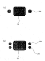
- the shielding member 26 can be in any shape providing the shielding member 26 can limit an irradiation amount of infrared rays. However, as shown in Fig.4 (a) and 4 (b) for instance it is preferable to dispose the shielding members 26a and 26b in a rod shape around the grown crystal 14 as needed.
- an irradiation amount of infrared rays from a constant direction can be limited on a constant basis by rotating the shielding member 26 in synchronization with the grown crystal 14 via a drive part 28 of a driving device (not shown) corresponding to an orientation of a growth of a single crystal.
- a single crystal can be grown to be in a shape such as a cylindrical shape and a prismatic column shape, whereby a single crystal having a large diameter can be grown.
- a material of the shielding member 26 is not restricted in particular. However, in consideration of a use at a high temperature, it is preferable to use the shielding member 26 provided with an alumina quality or a mullite quality.
- FIG. 5 A fourth embodiment of the floating zone melting apparatus in accordance with the present embodiment will be described below in detail with reference to the schematic views shown in Fig. 5 and Fig. 6 .
- the configuration of the floating zone melting apparatus 10d shown in Fig. 5 and Fig. 6 is equivalent to that of the floating zone melting apparatus 10a shown in Fig. 1 in the elementary sense. Consequently, elements equivalent to those illustrated in Fig. 1 are numerically numbered similarly in Fig. 5 and Fig. 6 and the detailed descriptions of the equivalent elements are omitted.
- the floating zone melting apparatus 10d shown in Fig. 5 and Fig. 6 is different from the floating zone melting apparatus 10a shown in Fig. 1 in terms of that an introduction gas pipe 34 made of transparent quartz is disposed between the inner wall of the sample chamber 30 and the sample rod 12.
- a vaporized material that is generated in heating and melting the sample rod 12 can be efficiently ejected together with the atmospheric gas 32 outside the sample chamber 30.
- a shape of the introduction gas pipe 34 shown in Fig. 5 is straight. As a gap between an inner diameter of the introduction gas pipe 34 and the sample rod 12 is smaller, a rate of flow of the atmospheric gas 32 can be increased and an effect of ejecting a vaporized material can be further improved advantageously. However, as an inner diameter of the introduction gas pipe 34 is smaller, an effect of introducing a vaporized material is smaller disadvantageously.
- a rate of flow of the atmospheric gas 32 that passes through the introduction gas pipe 34 is specified to be at least 10 cm per second.
- a vaporized material that is vaporized from a molten part 16 in the ordinary course of events is flown to the upper side by a convection current caused by a heat and is diffused to adhere to an inner wall of the sample chamber 30 made of a transparent quartz pipe conventionally.
- a rate of flow of the atmospheric gas 32 is specified as described above, a vaporized material can be efficiently ejected together with the atmospheric gas 32 outside the sample chamber 30.
- a fifth embodiment of the floating zone melting apparatus in accordance with the present embodiment will be described below in detail with reference to the schematic view shown in Fig. 7 .
- the configuration of the floating zone melting apparatus 10e shown in Fig. 7 is equivalent to that of the floating zone melting apparatus 10a shown in Fig. 1 in the elementary sense. Consequently, elements equivalent to those illustrated in Fig. 1 are numerically numbered similarly in Fig. 7 and the detailed descriptions of the equivalent elements are omitted.
- the floating zone melting apparatus 10e shown in Fig. 7 is different from the floating zone melting apparatus 10a shown in Fig, 1 in terms of that a circulation device 36 is disposed to be configured to supply an atmospheric gas 32 that has been ejected from the sample chamber 30 again into the sample chamber 30.
- the circulation device 36 is configured to separate a vaporized material that is generated in heating and melting the sample rod 12 and that is ejected together with the atmospheric gas 32 by using a filter member 38 in such a manner that only the atmospheric gas 32 can be supplied into the sample chamber 30.
- a costly atmospheric gas 32 can be used without a waste, whereby a cost for growing a single crystal can be suppressed.
- the vaporized material can be ejected together with the atmospheric gas 32 outside the sample chamber, and only an atmospheric gas 32 from which the vaporized material has been separated by using the filter member 38 can be circulated. Consequently, an inner wall of the sample chamber 30 made of a transparent quartz pipe can be maintained to be clean on a constant basis, and a growth of a single crystal can be continued in a stable manner.
- an infrared lamp unit 21 composed of an elliptical mirror 18 and an infrared lamp 20 is used as the infrared ray irradiation means.
- a laser oscillator (not shown) that is configured to emit an infrared ray can also be used as the infrared ray irradiation means.
- a laser oscillator is used as the infrared ray irradiation means
- a laser beam has a high directive property
- the laser oscillator can be prevented from being damaged and can be preferably used for the floating zone melting apparatus in accordance with the present invention.
- a disposal angle of a laser oscillator of the downward irradiation type and a laser oscillator of the upward irradiation type similarly to the infrared lamp units 21a and 21b described above, a disposal angle of a laser oscillator of the downward irradiation type can be in the range of 0° to 90° on the basis of the horizontal line and a disposal angle of a laser oscillator of the upward irradiation type can be in the range of 0° to -90° on the basis of the horizontal line although it is not restricted in particular.
- a disposal angle of a laser oscillator of the downward irradiation type is in the range of 25° to 35° on the basis of the horizontal line and a disposal angle of a laser oscillator of the upward irradiation type is in the range of 0° to -5° on the basis of the horizontal line.
- the molten solutions can be easily held, a single crystal can be grown in a stable manner, a phenomenon in which the dissolution of a sample makes progress at a dull pace can be suppressed, the interface of the solid phase and the liquid phase can be stabilized, and a single crystal of a high quality can be easily grown.
- infrared ray irradiation means of the downward irradiation type and four infrared ray irradiation means of the upward irradiation type are disposed or six infrared ray irradiation means of the downward irradiation type and six infrared ray irradiation means of the upward irradiation type are disposed.
- the number of infrared ray irradiation means of the downward irradiation type is equivalent to that of infrared ray irradiation means of the upward irradiation type.
- infrared ray irradiation means of the downward irradiation type and six infrared ray irradiation means of the upward irradiation type can also be disposed.
- infrared ray irradiation means of the downward irradiation type and six infrared ray irradiation means of the upward irradiation type can also be disposed.
- Eight elliptical mirrors made of a quartz glass were disposed on the horizontal face in such a manner that the elliptical mirrors share one focal point thereof with each other, and a halogen lamp was disposed at the other focal point of each of the elliptical mirrors, whereby eight halogen lamp units were configured.
- a lamp having an output power of 1000 W in a filament shape having a double helical structure was used for each of the halogen lamps.
- a sintered sample rod having a diameter of 20 mm was supported from the upper side by a sample rod supporting part, and a seed crystal was supported from the lower side by a growth crystal supporting part.
- halogen lamp units of the eight halogen lamp units are disposed at an interval of 90 degrees around the axis of the sample rod and at an angle of 30 degrees in such a manner that the sample in a rod shape is irradiated downward with an infrared ray from an oblique upper direction.
- the other four halogen lamp units of the eight halogen lamp units are disposed at an interval of 90 degrees around the axis of the sample rod and at an angle of 10 degrees in such a manner that the sample in a rod shape is irradiated upward with an infrared ray from an oblique lower direction.
- the position of four halogen lamp units of the downward irradiation type disposed on the upper side and the position of four halogen lamp units of the upward irradiation type disposed on the lower side are shifted from each other by 45 degrees in the case in which the halogen lamp units on the upper side and the halogen lamp units on the lower side are viewed from directly above.
- the eight halogen lamps were lighted. A voltage that was applied to the halogen lamps was increased by slow degrees while the sample rod and the seed crystal were rotated, and each of the end parts thereof was molten.
- the end part of the sample rod and the end part of the seed crystal were moved closer to each other, and the molten parts were made to be coalescent. After a stable molten material was formed, while the sample rod and the seed crystal were slowly moved downward at the constant speed, a melting operation of the sample rod and a growth of the crystal were continued, whereby a growth of a single crystal in a rod shape was carried out.
- a molten material was enabled to be easily held, and a single crystal of a high quality having a diameter of 55 mm was grown in a stable manner.
- a single crystal in a rod shape was grown under the conditions equivalent to those of Embodiment 1 except that a sample heating means in a tube shape was disposed in such a manner that a periphery of the sample rod was enclosed, a crystal heating means in a tube shape was disposed in such a manner that a periphery of the seed crystal (the grown crystal) was enclosed, the sample rod was heated by the sample heating means in advance, and the grown crystal of the seed crystal was heated by the crystal heating means in a continuous manner.
- a single crystal that was grown was a single crystal of a high quality having a diameter of 80 mm.
- a single crystal in a rod shape was grown under the conditions equivalent to those of Embodiment 1 except that a shielding member in a rod shape was disposed around the sample rod and the seed crystal and an irradiation amount of infrared rays that are emitted from the infrared lamp was limited in a growth of a single crystal.
- a single crystal in a rod shape was grown under the conditions equivalent to those of Embodiment 1 except that a laser oscillator of the downward irradiation type and a laser oscillator of the upward irradiation type were used as substitute for the halogen lamp unit of the downward irradiation type and the halogen lamp unit of the upward irradiation type.
- a molten material was enabled to be easily held, and a single crystal of a high quality having a diameter of 25 mm was grown in a stable manner.
- a single crystal in a rod shape was grown under the conditions equivalent to those of Embodiment 1 except that only the halogen lamp unit of the downward irradiation type was used.
Landscapes
- Chemical & Material Sciences (AREA)
- Physics & Mathematics (AREA)
- Electromagnetism (AREA)
- Engineering & Computer Science (AREA)
- Crystallography & Structural Chemistry (AREA)
- Materials Engineering (AREA)
- Metallurgy (AREA)
- Organic Chemistry (AREA)
- Crystals, And After-Treatments Of Crystals (AREA)
Claims (15)
- Zonenschmelzvorrichtung (10a; 10b; 10c; 10d; 10e) vom Typ Infrarotkonzentrierungserwärmung, bei der eine Probe (12) in eine Probenkammer (30) gebracht wird, die aus einem transparenten Quarzrohr hergestellt ist, ein Atmosphärengas (32) in die Probenkammer eingeleitet wird, Infrarotstrahlen, die von mehreren Infrarotstrahlen-Bestrahlungsmitteln (21) emittiert werden, auf die Probe zum Erwärmen und Schmelzen der Probe in diesem Zustand konzentriert werden, wodurch eine geschmolzene Lösung erhalten wird, und die geschmolzene Lösung an einem Impfkristall erstarrt, um so einen Einkristall (14) zu züchten,
wobei die mehreren Infrarotstrahlen-Bestrahlungsmittel Folgendes umfassen:mehrere Infrarotstrahlen-Bestrahlungsmittel (21 a) vom Typ der Abwärtsbestrahlung, die einen Infrarotstrahl von einer schrägen oberen Richtung nach unten emittieren; undmehrere Infrarotstrahlen-Bestrahlungsmittel (21 b) vom Typ der Aufwärtsbestrahlung, die einen Infrarotstrahl von einer schrägen unteren Richtung nach oben emittieren,wobei die mehreren Infrarotstrahlen-Bestrahlungsmittel (21 a) vom Typ der Abwärtsbestrahlung und die mehreren Infrarotstrahlen-Bestrahlungsmittel (21 b) vom Typ der Aufwärtsbestrahlung in regelmäßigen Abständen um eine Achse der Probe (12) als Mittelpunkt angeordnet sind, unddie Positionen der Infrarotstrahlen-Bestrahlungsmittel gegeneinander so verschoben sind, dass ein einzelnes Infrarotstrahlen-Bestrahlungsmittel vom Typ der Aufwärtsbestrahlung sich in einer Lücke der mehreren Infrarotstrahlen-Bestrahlungsmittel vom Typ der Abwärtsbestrahlung befindet, die in regelmäßigen Abständen angeordnet sind, falls die Infrarotstrahlen-Bestrahlungsmittel von zwei Stufen direkt von oben betrachtet werden. - Zonenschmelzvorrichtung nach Anspruch 1, wobei die Infrarotstrahlen-Bestrahlungsmittel (21 a) vom Typ der Abwärtsbestrahlung und die Infrarotstrahlen-Bestrahlungsmittel (21 b) vom Typ der Aufwärtsbestrahlung dafür ausgelegt sind, eine unabhängige Positionskontrolle derselben zu ermöglichen.
- Zonenschmelzvorrichtung nach Anspruch 1 oder 2, wobei das Infrarotstrahlen-Bestrahlungsmittel (21) eine Infrarotlampeneinheit ist, die einen drehbaren ellipsoiden reflektierenden Spiegel (18) umfasst, in dem eine Innenfläche als Reflektionsfläche verwendet wird und eine Infrarotlampe (20) in einem Brennpunkt derselben angeordnet ist.
- Zonenschmelzvorrichtung nach Anspruch 1 oder 2, wobei das Infrarotstrahlen-Bestrahlungsmittel (21) ein Laseroszillator ist, der zum Emittieren eines Infrarotstrahls durch einen Laserstrahl ausgelegt ist.
- Zonenschmelzvorrichtung nach einem der Ansprüche 1 bis 4, wobei die Infrarotstrahlen-Bestrahlungsmittel (21 a) vom Typ der Abwärtsbestrahlung und die Infrarotstrahlen-Bestrahlungsmittel (21 b) vom Typ der Aufwärtsbestrahlung mit einem Bestrahlungspositionskontrollmechanismus versehen sind, der zum unabhängigen Einstellen eines Bestrahlungswinkels und einer Bestrahlungsmenge von Infrarotstrahlen ausgelegt ist.
- Zonenschmelzvorrichtung nach einem der Ansprüche 1 bis 5, wobei das Infrarotstrahlen-Bestrahlunüsmittel (21) mit einem horizontalen Positionskontrollmechanismus für eine horizontale Bewegung in einer Bestrahlungsrichtung von einer Position aus versehen ist, in der die Probe (12) als Mittelpunkt angeordnet ist.
- Zonenschmelzvorrichtung nach einem der Ansprüche 1 bis 6, wobei ein Probenerwärmungsmittel (22) in Rohrform so angeordnet ist, dass eine Peripherie der Probe (12) umschlossen ist.
- Zonenschmelzvorrichtung nach Anspruch 7, die ferner einen Positionskontrollmechanismus umfasst, der zum Steuern einer Position des Probenerwärmungsmittels (22) ausgelegt ist.
- Zonenschmelzvorrichtung nach einem der Ansprüche 1 bis 8, wobei ein Kristallerwärmungsmittel (24) in Rohrform so angeordnet ist, dass eine Peripherie des gezüchteten Kristalls (14) umschlossen ist.
- Zonenschmelzvorrichtung nach Anspruch 9, die ferner einen Positionskontrollmechanismus umfasst, der zum Steuern einer Position des Kristallerwärmungsmittels (24) ausgelegt ist.
- Zonenschmelzvorrichtung nach einem der Ansprüche 1 bis 10, die ferner einen Mechanismus umfasst, bei dem ein Abschirmelement (26), welches zum Begrenzen einer Strahlungsmenge von Infrarotstrahlen ausgelegt ist, die vom Infrarotstrahlen-Bestrahlungsmittel (21) emittiert werden, um die Probe (12) und den gezüchteten Kristall (14) herum angeordnet ist und bei dem eine Synchronisierung mit einer Drehung und einer Bewegung des gezüchteten Kristalls ermöglicht wird.
- Zonenschmelzvorrichtung nach einem der Ansprüche 1 bis 11, wobei ein Einleitungsgasrohr (34), das aus transparentem Quarz hergestellt ist, das zum effizienten Ausstoßen eines verdampften Materials, welches beim Erwärmen und Schmelzen der Probe (12) erzeugt wird, zusammen mit dem Atmosphärengas außerhalb der Probenkammer ausgelegt ist, zwischen einer Innenwand der Probenkammer und der Probe angeordnet ist.
- Zonenschmelzvorrichtung nach Anspruch 12, wobei ein Durchmesser einer Form eines Endteils, der sich auf der Seite zum Erwärmen und Schmelzen der Probe für das Einleitungsgasrohr (34) befindet, größer als der von anderen Teilen ist.
- Zonenschmelzvorrichtung nach Anspruch 12 oder 13, wobei ein Atmosphärengas (32) so eingeleitet werden kann, dass eine Durchflussrate des Atmosphärengases, welches durch das Einleitungsgasrohr (34) strömt, mindestens 10 cm pro Sekunde beträgt.
- Zonenschmelzvorrichtung nach einem der Ansprüche 1 bis 14, die ferner eine Umwälzvorrichtung (36) umfasst, welche zum Zuführen eines Atmosphärengases (32), das aus der Probenkammer (30) ausgestoßen wurde, zurück in die Probenkammer ausgelegt ist, wobei die Umwälzvorrichtung vorzugsweise dafür ausgelegt ist, verdampftes Material, das beim Erwärmen und Schmelzen der Probe (12) erzeugt wird und das zusammen mit dem Atmosphärengas ausgestoßen wird, unter Verwendung eines Filterelementes (38) derart abzutrennen, dass nur das Atmosphärengas der Probenkammer zugeführt wird.
Applications Claiming Priority (2)
| Application Number | Priority Date | Filing Date | Title |
|---|---|---|---|
| JP2007332559 | 2007-12-25 | ||
| PCT/JP2008/072957 WO2009081811A1 (ja) | 2007-12-25 | 2008-12-17 | 浮遊帯域溶融装置 |
Publications (3)
| Publication Number | Publication Date |
|---|---|
| EP2246461A1 EP2246461A1 (de) | 2010-11-03 |
| EP2246461A4 EP2246461A4 (de) | 2011-05-25 |
| EP2246461B1 true EP2246461B1 (de) | 2013-03-20 |
Family
ID=40801115
Family Applications (1)
| Application Number | Title | Priority Date | Filing Date |
|---|---|---|---|
| EP08864615A Active EP2246461B1 (de) | 2007-12-25 | 2008-12-17 | Vorrichtung zum schwebezonenschmelzen |
Country Status (7)
| Country | Link |
|---|---|
| US (1) | US20100307406A1 (de) |
| EP (1) | EP2246461B1 (de) |
| JP (1) | JP5279727B2 (de) |
| KR (1) | KR101286431B1 (de) |
| CN (1) | CN101910473A (de) |
| TW (1) | TWI435958B (de) |
| WO (1) | WO2009081811A1 (de) |
Families Citing this family (21)
| Publication number | Priority date | Publication date | Assignee | Title |
|---|---|---|---|---|
| JP4895134B2 (ja) * | 2008-01-24 | 2012-03-14 | 株式会社クリスタルシステム | 浮遊帯域溶融装置 |
| DE102011089429A1 (de) * | 2011-12-21 | 2013-06-27 | Siltronic Ag | Verfahren und Vorrichtung zur Herstellung eines Einkristalls |
| JP6006191B2 (ja) * | 2013-10-23 | 2016-10-12 | 伸 阿久津 | 単結晶製造装置および単結晶製造方法 |
| JP6778376B2 (ja) * | 2015-01-29 | 2020-11-04 | 国立大学法人山梨大学 | 浮遊帯域溶融法およびこれを用いた装置 |
| JP6106815B2 (ja) * | 2015-02-09 | 2017-04-05 | 伸 阿久津 | 単結晶製造装置および単結晶製造方法 |
| JP2017154919A (ja) * | 2016-03-01 | 2017-09-07 | 株式会社クリスタルシステム | 浮遊帯域溶融装置 |
| JP6669355B2 (ja) * | 2016-04-19 | 2020-03-18 | 株式会社クリスタルシステム | 浮遊帯域溶融装置 |
| WO2018003386A1 (ja) * | 2016-06-29 | 2018-01-04 | 株式会社クリスタルシステム | 単結晶製造装置および単結晶製造方法 |
| US20190032242A1 (en) * | 2016-07-28 | 2019-01-31 | Crystal Systems Corporation | Single-Crystal Production Equipment |
| DE102017202311A1 (de) * | 2017-02-14 | 2018-08-16 | Siltronic Ag | Verfahren und Anlage zum Ziehen eines Einkristalls nach dem FZ-Verfahren |
| RU2656331C1 (ru) * | 2017-10-17 | 2018-06-04 | федеральное государственное бюджетное образовательное учреждение высшего образования "Национальный исследовательский университет "МЭИ" (ФГБОУ ВО "НИУ "МЭИ") | Устройство для выращивания монокристаллов |
| WO2019186870A1 (ja) | 2018-03-29 | 2019-10-03 | 株式会社クリスタルシステム | 単結晶製造装置および単結晶製造方法 |
| CN110546315B (zh) | 2018-03-29 | 2021-09-03 | 株式会社水晶系统 | 单晶制造装置 |
| CN110528061A (zh) * | 2018-05-23 | 2019-12-03 | 中国科学院金属研究所 | 一种激光辅助加热生长大尺寸晶体的方法及专用设备 |
| CN110528062A (zh) * | 2018-05-23 | 2019-12-03 | 中国科学院金属研究所 | 激光辅助加热生长大尺寸钛合金晶体的方法及专用设备 |
| RU2734936C1 (ru) * | 2020-06-01 | 2020-10-26 | Федеральное государственное бюджетное учреждение науки Институт химии твердого тела Уральского отделения Российской академии наук | Способ получения монокристалла оксида ниобия |
| EP4265827A4 (de) | 2020-12-15 | 2024-12-18 | Crystal Systems Corporation | Vorrichtung zur produktion dünner plattenförmiger einkristalle und verfahren zur produktion dünner plattenförmiger einkristalle |
| JP7690184B2 (ja) * | 2020-12-15 | 2025-06-10 | 株式会社クリスタルシステム | 薄板状単結晶製造装置および薄板状単結晶製造方法 |
| JP7637544B2 (ja) * | 2021-03-25 | 2025-02-28 | Tdk株式会社 | 結晶製造方法、結晶製造装置、及び単結晶 |
| JP7720080B2 (ja) * | 2021-08-11 | 2025-08-07 | 株式会社クリスタルシステム | 薄板状単結晶製造装置および薄板状単結晶製造方法 |
| DK4144894T3 (da) * | 2021-09-07 | 2025-09-08 | Siltronic Ag | Fremgangsmåde til fremstilling af et silicium-enkeltkrystal |
Family Cites Families (27)
| Publication number | Priority date | Publication date | Assignee | Title |
|---|---|---|---|---|
| JPS4729047Y1 (de) * | 1968-04-25 | 1972-08-31 | ||
| JPS4914010B1 (de) * | 1969-01-10 | 1974-04-04 | ||
| JPS4993280A (de) * | 1973-01-10 | 1974-09-05 | ||
| DE2813760A1 (de) * | 1978-03-30 | 1979-10-04 | Siemens Ag | Vorrichtung zur beeinflussung der form der phasengrenzflaechen fest/fluessig beim herstellen von versetzungsfreien siliciumeinkristallstaeben durch tiegelfreies zonenschmelzen |
| JPS5590498A (en) * | 1978-12-28 | 1980-07-09 | Seiko Epson Corp | Single crystal producing device |
| JPS57106596A (en) * | 1980-12-23 | 1982-07-02 | Seiko Instr & Electronics Ltd | Method for growing plate-like single crystal |
| JPS5954690A (ja) * | 1982-09-18 | 1984-03-29 | Sony Corp | 結晶育成方法 |
| US4602980A (en) * | 1984-10-01 | 1986-07-29 | Solavolt International | Method for improving crystallinity of semiconductor ribbon |
| EP0211933A1 (de) * | 1985-02-11 | 1987-03-04 | Solavolt International | Verfahren eines band-zu-band-umwandlungssystems und vorrichtung dafür |
| US4888302A (en) * | 1987-11-25 | 1989-12-19 | North American Philips Corporation | Method of reduced stress recrystallization |
| JP2734485B2 (ja) * | 1990-09-21 | 1998-03-30 | 三菱重工業株式会社 | 単結晶成長装置 |
| JPH04367585A (ja) * | 1991-06-13 | 1992-12-18 | Nisshin Steel Co Ltd | 集光加熱式単結晶製造装置 |
| JPH0543378A (ja) * | 1991-08-02 | 1993-02-23 | Nisshin Steel Co Ltd | 単結晶製造装置 |
| JPH06234509A (ja) * | 1993-02-08 | 1994-08-23 | Toshiba Corp | 酸化物超電導体の製造方法と酸化物超電導体の製造装置 |
| JP3643397B2 (ja) * | 1995-01-25 | 2005-04-27 | 株式会社ケイイーディー | 浮遊帯域溶融装置 |
| JP2982642B2 (ja) * | 1995-02-27 | 1999-11-29 | ニチデン機械株式会社 | 赤外線加熱単結晶製造装置 |
| JPH09235171A (ja) | 1995-09-18 | 1997-09-09 | Crystal Syst:Kk | 浮遊帯域溶融装置 |
| US5762707A (en) * | 1995-09-18 | 1998-06-09 | Cristal Systems, Inc. | Floating zone melting apparatus |
| JP3237564B2 (ja) * | 1997-03-12 | 2001-12-10 | 株式会社村田製作所 | 単結晶育成方法 |
| JP3106182B2 (ja) * | 1997-09-22 | 2000-11-06 | 科学技術庁金属材料技術研究所長 | バルク単結晶の製造方法 |
| JP2002362997A (ja) * | 2001-06-11 | 2002-12-18 | Murata Mfg Co Ltd | 鉄ガーネット単結晶の処理方法、鉄ガーネット単結晶、マイクロ波デバイスおよびオプティカルデバイス |
| US6838066B2 (en) * | 2002-09-13 | 2005-01-04 | Air Products And Chemicals, Inc. | Process for recovery, purification, and recycle of argon |
| JP2005247668A (ja) * | 2004-03-08 | 2005-09-15 | Nec Machinery Corp | 単結晶育成装置 |
| JP4738966B2 (ja) * | 2005-10-07 | 2011-08-03 | 株式会社クリスタルシステム | 浮遊帯域溶融装置 |
| JP5067596B2 (ja) * | 2005-11-24 | 2012-11-07 | 独立行政法人産業技術総合研究所 | サファイア単結晶製造方法及びその製造装置 |
| EP2128308B1 (de) * | 2007-01-10 | 2012-03-14 | Crystal Systems Corporation | Vorrichtung zum tiegelfreien zonenschmelzen |
| JP4895134B2 (ja) * | 2008-01-24 | 2012-03-14 | 株式会社クリスタルシステム | 浮遊帯域溶融装置 |
-
2008
- 2008-12-17 WO PCT/JP2008/072957 patent/WO2009081811A1/ja not_active Ceased
- 2008-12-17 US US12/747,059 patent/US20100307406A1/en not_active Abandoned
- 2008-12-17 EP EP08864615A patent/EP2246461B1/de active Active
- 2008-12-17 CN CN200880123151.9A patent/CN101910473A/zh active Pending
- 2008-12-17 JP JP2009547058A patent/JP5279727B2/ja active Active
- 2008-12-17 KR KR1020107014466A patent/KR101286431B1/ko not_active Expired - Fee Related
- 2008-12-25 TW TW097150583A patent/TWI435958B/zh not_active IP Right Cessation
Also Published As
| Publication number | Publication date |
|---|---|
| JP5279727B2 (ja) | 2013-09-04 |
| JPWO2009081811A1 (ja) | 2011-05-06 |
| KR101286431B1 (ko) | 2013-07-18 |
| EP2246461A1 (de) | 2010-11-03 |
| EP2246461A4 (de) | 2011-05-25 |
| KR20100100920A (ko) | 2010-09-15 |
| WO2009081811A1 (ja) | 2009-07-02 |
| US20100307406A1 (en) | 2010-12-09 |
| TW200942652A (en) | 2009-10-16 |
| TWI435958B (zh) | 2014-05-01 |
| CN101910473A (zh) | 2010-12-08 |
Similar Documents
| Publication | Publication Date | Title |
|---|---|---|
| EP2246461B1 (de) | Vorrichtung zum schwebezonenschmelzen | |
| US7682452B2 (en) | Apparatus and methods of growing void-free crystalline ceramic products | |
| KR101157311B1 (ko) | 부유대역용융장치 | |
| TWI400368B (zh) | 浮游帶域熔融裝置 | |
| CN107949665B (zh) | 单晶制造装置 | |
| JP2020063163A (ja) | 単結晶製造装置 | |
| KR20120061750A (ko) | 실리카 유리 도가니의 제조 방법 및 제조 장치 | |
| WO2002027077A1 (fr) | Procede de fabrication d'un monocristal en silicium et dispositif de fabrication d'un monocristal semiconducteur | |
| KR102698389B1 (ko) | 박판상 단결정 제조 장치 및 박판상 단결정 제조 방법 | |
| CN114829684A (zh) | 单晶纤维制造装置及单晶纤维制造方法 | |
| JPH06100394A (ja) | 単結晶製造用原料供給方法及び装置 | |
| EP1910246B1 (de) | Verfahren zur herstellung dichter blöcke | |
| JP6607651B1 (ja) | 単結晶製造装置 | |
| JPH05294783A (ja) | シリコン単結晶の製造装置 | |
| JP2005247668A (ja) | 単結晶育成装置 | |
| JPH05117077A (ja) | 単結晶引上装置 | |
| JP4895134B2 (ja) | 浮遊帯域溶融装置 | |
| JPH0612477U (ja) | 引上装置 | |
| JP2982642B2 (ja) | 赤外線加熱単結晶製造装置 | |
| JPH02149488A (ja) | レーザ加熱ファイバ製造装置 | |
| JPH08208368A (ja) | 浮遊帯域溶融装置 | |
| JPH08104511A (ja) | 結晶板の製造方法 | |
| JPS5988327A (ja) | 石英ガラスの合成方法 | |
| Vu et al. | 210 RP POPLAWSKY | |
| JPH05163095A (ja) | 単結晶引上装置 |
Legal Events
| Date | Code | Title | Description |
|---|---|---|---|
| PUAI | Public reference made under article 153(3) epc to a published international application that has entered the european phase |
Free format text: ORIGINAL CODE: 0009012 |
|
| 17P | Request for examination filed |
Effective date: 20100706 |
|
| AK | Designated contracting states |
Kind code of ref document: A1 Designated state(s): AT BE BG CH CY CZ DE DK EE ES FI FR GB GR HR HU IE IS IT LI LT LU LV MC MT NL NO PL PT RO SE SI SK TR |
|
| AX | Request for extension of the european patent |
Extension state: AL BA MK RS |
|
| DAX | Request for extension of the european patent (deleted) | ||
| A4 | Supplementary search report drawn up and despatched |
Effective date: 20110427 |
|
| GRAP | Despatch of communication of intention to grant a patent |
Free format text: ORIGINAL CODE: EPIDOSNIGR1 |
|
| GRAS | Grant fee paid |
Free format text: ORIGINAL CODE: EPIDOSNIGR3 |
|
| GRAA | (expected) grant |
Free format text: ORIGINAL CODE: 0009210 |
|
| AK | Designated contracting states |
Kind code of ref document: B1 Designated state(s): AT BE BG CH CY CZ DE DK EE ES FI FR GB GR HR HU IE IS IT LI LT LU LV MC MT NL NO PL PT RO SE SI SK TR |
|
| REG | Reference to a national code |
Ref country code: GB Ref legal event code: FG4D |
|
| REG | Reference to a national code |
Ref country code: CH Ref legal event code: EP |
|
| REG | Reference to a national code |
Ref country code: IE Ref legal event code: FG4D |
|
| REG | Reference to a national code |
Ref country code: AT Ref legal event code: REF Ref document number: 602157 Country of ref document: AT Kind code of ref document: T Effective date: 20130415 |
|
| REG | Reference to a national code |
Ref country code: DE Ref legal event code: R096 Ref document number: 602008023134 Country of ref document: DE Effective date: 20130516 |
|
| PG25 | Lapsed in a contracting state [announced via postgrant information from national office to epo] |
Ref country code: ES Free format text: LAPSE BECAUSE OF FAILURE TO SUBMIT A TRANSLATION OF THE DESCRIPTION OR TO PAY THE FEE WITHIN THE PRESCRIBED TIME-LIMIT Effective date: 20130701 Ref country code: SE Free format text: LAPSE BECAUSE OF FAILURE TO SUBMIT A TRANSLATION OF THE DESCRIPTION OR TO PAY THE FEE WITHIN THE PRESCRIBED TIME-LIMIT Effective date: 20130320 Ref country code: LT Free format text: LAPSE BECAUSE OF FAILURE TO SUBMIT A TRANSLATION OF THE DESCRIPTION OR TO PAY THE FEE WITHIN THE PRESCRIBED TIME-LIMIT Effective date: 20130320 Ref country code: NO Free format text: LAPSE BECAUSE OF FAILURE TO SUBMIT A TRANSLATION OF THE DESCRIPTION OR TO PAY THE FEE WITHIN THE PRESCRIBED TIME-LIMIT Effective date: 20130620 Ref country code: BG Free format text: LAPSE BECAUSE OF FAILURE TO SUBMIT A TRANSLATION OF THE DESCRIPTION OR TO PAY THE FEE WITHIN THE PRESCRIBED TIME-LIMIT Effective date: 20130620 |
|
| REG | Reference to a national code |
Ref country code: AT Ref legal event code: MK05 Ref document number: 602157 Country of ref document: AT Kind code of ref document: T Effective date: 20130320 |
|
| REG | Reference to a national code |
Ref country code: LT Ref legal event code: MG4D |
|
| PG25 | Lapsed in a contracting state [announced via postgrant information from national office to epo] |
Ref country code: SI Free format text: LAPSE BECAUSE OF FAILURE TO SUBMIT A TRANSLATION OF THE DESCRIPTION OR TO PAY THE FEE WITHIN THE PRESCRIBED TIME-LIMIT Effective date: 20130320 Ref country code: GR Free format text: LAPSE BECAUSE OF FAILURE TO SUBMIT A TRANSLATION OF THE DESCRIPTION OR TO PAY THE FEE WITHIN THE PRESCRIBED TIME-LIMIT Effective date: 20130621 Ref country code: LV Free format text: LAPSE BECAUSE OF FAILURE TO SUBMIT A TRANSLATION OF THE DESCRIPTION OR TO PAY THE FEE WITHIN THE PRESCRIBED TIME-LIMIT Effective date: 20130320 Ref country code: FI Free format text: LAPSE BECAUSE OF FAILURE TO SUBMIT A TRANSLATION OF THE DESCRIPTION OR TO PAY THE FEE WITHIN THE PRESCRIBED TIME-LIMIT Effective date: 20130320 |
|
| REG | Reference to a national code |
Ref country code: NL Ref legal event code: VDEP Effective date: 20130320 |
|
| PG25 | Lapsed in a contracting state [announced via postgrant information from national office to epo] |
Ref country code: BE Free format text: LAPSE BECAUSE OF FAILURE TO SUBMIT A TRANSLATION OF THE DESCRIPTION OR TO PAY THE FEE WITHIN THE PRESCRIBED TIME-LIMIT Effective date: 20130320 Ref country code: HR Free format text: LAPSE BECAUSE OF FAILURE TO SUBMIT A TRANSLATION OF THE DESCRIPTION OR TO PAY THE FEE WITHIN THE PRESCRIBED TIME-LIMIT Effective date: 20130320 |
|
| PG25 | Lapsed in a contracting state [announced via postgrant information from national office to epo] |
Ref country code: SK Free format text: LAPSE BECAUSE OF FAILURE TO SUBMIT A TRANSLATION OF THE DESCRIPTION OR TO PAY THE FEE WITHIN THE PRESCRIBED TIME-LIMIT Effective date: 20130320 Ref country code: RO Free format text: LAPSE BECAUSE OF FAILURE TO SUBMIT A TRANSLATION OF THE DESCRIPTION OR TO PAY THE FEE WITHIN THE PRESCRIBED TIME-LIMIT Effective date: 20130320 Ref country code: EE Free format text: LAPSE BECAUSE OF FAILURE TO SUBMIT A TRANSLATION OF THE DESCRIPTION OR TO PAY THE FEE WITHIN THE PRESCRIBED TIME-LIMIT Effective date: 20130320 Ref country code: IS Free format text: LAPSE BECAUSE OF FAILURE TO SUBMIT A TRANSLATION OF THE DESCRIPTION OR TO PAY THE FEE WITHIN THE PRESCRIBED TIME-LIMIT Effective date: 20130720 Ref country code: PT Free format text: LAPSE BECAUSE OF FAILURE TO SUBMIT A TRANSLATION OF THE DESCRIPTION OR TO PAY THE FEE WITHIN THE PRESCRIBED TIME-LIMIT Effective date: 20130722 Ref country code: NL Free format text: LAPSE BECAUSE OF FAILURE TO SUBMIT A TRANSLATION OF THE DESCRIPTION OR TO PAY THE FEE WITHIN THE PRESCRIBED TIME-LIMIT Effective date: 20130320 Ref country code: CZ Free format text: LAPSE BECAUSE OF FAILURE TO SUBMIT A TRANSLATION OF THE DESCRIPTION OR TO PAY THE FEE WITHIN THE PRESCRIBED TIME-LIMIT Effective date: 20130320 Ref country code: AT Free format text: LAPSE BECAUSE OF FAILURE TO SUBMIT A TRANSLATION OF THE DESCRIPTION OR TO PAY THE FEE WITHIN THE PRESCRIBED TIME-LIMIT Effective date: 20130320 |
|
| PG25 | Lapsed in a contracting state [announced via postgrant information from national office to epo] |
Ref country code: CY Free format text: LAPSE BECAUSE OF FAILURE TO SUBMIT A TRANSLATION OF THE DESCRIPTION OR TO PAY THE FEE WITHIN THE PRESCRIBED TIME-LIMIT Effective date: 20130320 Ref country code: PL Free format text: LAPSE BECAUSE OF FAILURE TO SUBMIT A TRANSLATION OF THE DESCRIPTION OR TO PAY THE FEE WITHIN THE PRESCRIBED TIME-LIMIT Effective date: 20130320 |
|
| PLBE | No opposition filed within time limit |
Free format text: ORIGINAL CODE: 0009261 |
|
| STAA | Information on the status of an ep patent application or granted ep patent |
Free format text: STATUS: NO OPPOSITION FILED WITHIN TIME LIMIT |
|
| PG25 | Lapsed in a contracting state [announced via postgrant information from national office to epo] |
Ref country code: DK Free format text: LAPSE BECAUSE OF FAILURE TO SUBMIT A TRANSLATION OF THE DESCRIPTION OR TO PAY THE FEE WITHIN THE PRESCRIBED TIME-LIMIT Effective date: 20130320 |
|
| 26N | No opposition filed |
Effective date: 20140102 |
|
| PG25 | Lapsed in a contracting state [announced via postgrant information from national office to epo] |
Ref country code: IT Free format text: LAPSE BECAUSE OF FAILURE TO SUBMIT A TRANSLATION OF THE DESCRIPTION OR TO PAY THE FEE WITHIN THE PRESCRIBED TIME-LIMIT Effective date: 20130320 |
|
| REG | Reference to a national code |
Ref country code: DE Ref legal event code: R097 Ref document number: 602008023134 Country of ref document: DE Effective date: 20140102 |
|
| REG | Reference to a national code |
Ref country code: CH Ref legal event code: PL |
|
| PG25 | Lapsed in a contracting state [announced via postgrant information from national office to epo] |
Ref country code: LU Free format text: LAPSE BECAUSE OF FAILURE TO SUBMIT A TRANSLATION OF THE DESCRIPTION OR TO PAY THE FEE WITHIN THE PRESCRIBED TIME-LIMIT Effective date: 20131217 Ref country code: MC Free format text: LAPSE BECAUSE OF FAILURE TO SUBMIT A TRANSLATION OF THE DESCRIPTION OR TO PAY THE FEE WITHIN THE PRESCRIBED TIME-LIMIT Effective date: 20130320 |
|
| REG | Reference to a national code |
Ref country code: IE Ref legal event code: MM4A |
|
| PG25 | Lapsed in a contracting state [announced via postgrant information from national office to epo] |
Ref country code: IE Free format text: LAPSE BECAUSE OF NON-PAYMENT OF DUE FEES Effective date: 20131217 Ref country code: CH Free format text: LAPSE BECAUSE OF NON-PAYMENT OF DUE FEES Effective date: 20131231 Ref country code: LI Free format text: LAPSE BECAUSE OF NON-PAYMENT OF DUE FEES Effective date: 20131231 |
|
| PG25 | Lapsed in a contracting state [announced via postgrant information from national office to epo] |
Ref country code: TR Free format text: LAPSE BECAUSE OF FAILURE TO SUBMIT A TRANSLATION OF THE DESCRIPTION OR TO PAY THE FEE WITHIN THE PRESCRIBED TIME-LIMIT Effective date: 20130320 |
|
| PG25 | Lapsed in a contracting state [announced via postgrant information from national office to epo] |
Ref country code: HU Free format text: LAPSE BECAUSE OF FAILURE TO SUBMIT A TRANSLATION OF THE DESCRIPTION OR TO PAY THE FEE WITHIN THE PRESCRIBED TIME-LIMIT; INVALID AB INITIO Effective date: 20081217 |
|
| PG25 | Lapsed in a contracting state [announced via postgrant information from national office to epo] |
Ref country code: MT Free format text: LAPSE BECAUSE OF FAILURE TO SUBMIT A TRANSLATION OF THE DESCRIPTION OR TO PAY THE FEE WITHIN THE PRESCRIBED TIME-LIMIT Effective date: 20130320 |
|
| REG | Reference to a national code |
Ref country code: FR Ref legal event code: PLFP Year of fee payment: 8 |
|
| REG | Reference to a national code |
Ref country code: FR Ref legal event code: PLFP Year of fee payment: 9 |
|
| REG | Reference to a national code |
Ref country code: FR Ref legal event code: PLFP Year of fee payment: 10 |
|
| REG | Reference to a national code |
Ref country code: DE Ref legal event code: R082 Ref document number: 602008023134 Country of ref document: DE |
|
| PGFP | Annual fee paid to national office [announced via postgrant information from national office to epo] |
Ref country code: DE Payment date: 20241218 Year of fee payment: 17 |
|
| PGFP | Annual fee paid to national office [announced via postgrant information from national office to epo] |
Ref country code: GB Payment date: 20241220 Year of fee payment: 17 |
|
| PGFP | Annual fee paid to national office [announced via postgrant information from national office to epo] |
Ref country code: FR Payment date: 20241227 Year of fee payment: 17 |