EP2295813A2 - Rotor de pompe turbo-moléculaire - Google Patents
Rotor de pompe turbo-moléculaire Download PDFInfo
- Publication number
- EP2295813A2 EP2295813A2 EP10007376A EP10007376A EP2295813A2 EP 2295813 A2 EP2295813 A2 EP 2295813A2 EP 10007376 A EP10007376 A EP 10007376A EP 10007376 A EP10007376 A EP 10007376A EP 2295813 A2 EP2295813 A2 EP 2295813A2
- Authority
- EP
- European Patent Office
- Prior art keywords
- rotor
- turbomolecular pump
- pumping
- pump
- pump rotor
- Prior art date
- Legal status (The legal status is an assumption and is not a legal conclusion. Google has not performed a legal analysis and makes no representation as to the accuracy of the status listed.)
- Granted
Links
Images


Classifications
-
- F—MECHANICAL ENGINEERING; LIGHTING; HEATING; WEAPONS; BLASTING
- F04—POSITIVE - DISPLACEMENT MACHINES FOR LIQUIDS; PUMPS FOR LIQUIDS OR ELASTIC FLUIDS
- F04D—NON-POSITIVE-DISPLACEMENT PUMPS
- F04D19/00—Axial-flow pumps
- F04D19/02—Multi-stage pumps
- F04D19/04—Multi-stage pumps specially adapted to the production of a high vacuum, e.g. molecular pumps
- F04D19/042—Turbomolecular vacuum pumps
-
- F—MECHANICAL ENGINEERING; LIGHTING; HEATING; WEAPONS; BLASTING
- F04—POSITIVE - DISPLACEMENT MACHINES FOR LIQUIDS; PUMPS FOR LIQUIDS OR ELASTIC FLUIDS
- F04D—NON-POSITIVE-DISPLACEMENT PUMPS
- F04D29/00—Details, component parts, or accessories
- F04D29/26—Rotors specially for elastic fluids
- F04D29/32—Rotors specially for elastic fluids for axial flow pumps
- F04D29/321—Rotors specially for elastic fluids for axial flow pumps for axial flow compressors
Definitions
- the invention relates to a turbomolecular pump rotor according to the preamble of the first claim.
- a first common design is to provide disks with a series of turbo blades and to shrivel or clamp them onto a shaft.
- Such a structure shows the EP-A-1559914 , Especially in turbomolecular pumps with high pumping speed and five-axis active magnetic bearing this leads to large overall lengths.
- Another common design creates a shorter design by a central shaft is surrounded by the necessary drive and bearing components of a rotor body, the shaft and rotor body are connected to each other frontally.
- the rotor body may be constructed of a plurality of disks, such as the DE 1728487 shows.
- the speeds of turbomolecular pumps are in the range of tens of thousands of revolutions per minute.
- turbomolecular pump rotor with the features of the first claim, a turbomolecular pump according to claim 6 and a rotor component according to claim 8.
- the claims 2 to 5 and 7 indicate advantageous developments of the invention.
- the safety in the case of the burst is increased since the turbomolecular pump rotor according to claim 1 is not a continuous rotor body. This reduces the size of the debris and lengthens the tearing process. As a result, an overload of the connection of the housing of the turbo pump and the recipient to be pumped is prevented.
- the first rotor part which includes the first pumping structure and the second pumping structure, may be made of flat material, which is available at a higher budget for a given cost. This leads to a further increase in security.
- the first rotor part has a recess which extends in the axial direction and lies radially inward, that is, extends from the axis of symmetry and rotation in the radial direction in such a way that a cavity is created.
- a cavity advantageously other components may be arranged, for example, a labyrinth seal or parts of the storage and the drive. This saves construction length.
- the third pump structure As a bladed rotor disk.
- this increases safety, since such individual disks behave uncritically in the burst; on the other hand, the disk construction allows greater freedom in the design of the blades, especially in the high-vacuum range.
- the blades In the high vacuum range, the blades are set steeply against the direction of movement and extend long in the axial and tangential direction. If several rows of blades for this pressure range are arranged on a common body, the design is restricted by manufacturing methods such as milling and sawing. This does not apply to disks, so that better vacuum data is achieved in this way.
- turbomolecular pump rotor has a second rotor part with at least two pump structures.
- a first embodiment of a turbomolecular pump rotor is in a section along the axis of rotation in FIG. 1 shown.
- the figure shows first part 160 of the housing of the turbomolecular vacuum pump, hereinafter turbopump.
- This part takes on the motor coil 161, which generates a rotating magnetic field. This cooperates with the motor magnet 162 and sets the turbomolecular pump rotor in rapid rotation.
- the motor magnet is covered by a sleeve 163 and secured against the negative effects of the applied centrifugal forces secured to the shaft 132 of the turbomolecular pump rotor.
- the shaft has on one of its end faces, preferably facing the high vacuum side, a recess in which at least one permanent magnet ring 190 is arranged, which forms the rotor-side part of a lubricant-free magnetic bearing for supporting the turbomolecular pump rotor.
- the turbopump has a pump stator which comprises stator disks 112, 116, 120 and 124 provided with vanes as stator-side pump structures, which are axially spaced apart from one another by means of spacer rings 113, 117, 121 and 125.
- stator disks 112, 116, 120 and 124 provided with vanes as stator-side pump structures, which are axially spaced apart from one another by means of spacer rings 113, 117, 121 and 125.
- the Pump stator also comprises a Holweckstator 128 as a further stator-side pumping structure.
- the turbomolecular pump rotor includes rotor blade rings 111, 115, 119 and 123 and a rotor sleeve 127 as rotor-side pumping structures.
- the rotor blade rings are each formed by blades extending radially outward on the rotor and for each of the rotor blade rings in one of the planes 150, 151, 152 and 153 lie.
- the Best Trentssebene the rotor sleeve forms the plane 154.
- the levels 150, 151, 152, 153 and 154 are spaced apart in the axial direction.
- the pumping structures 111 and 112 cooperate and form a first pumping stage 110, which is arranged on the suction side and works in the high-vacuum range.
- the pumping structures 115 and 116, 119 and 120, as well as 123 and 124 form further pumping stages 114, 118 and 122 for the middle pressure range.
- Rotor sleeve 127 and Holweckstator 128 together form a Holweckcut.
- the shaft carries the first rotor component 101, which comprises the blades of the rotor blade rings 119 and 123, advantageously the blades are integral components of the first rotor component.
- the first rotor component also carries the rotor sleeve 127, which comprises a carbon fiber composite material.
- the first rotor part has a recess 130. This extends in the axial and radial directions such that a cavity is formed. In these project parts of the housing 160 and the motor coil 161, so that a short length of the turbo pump is achieved.
- a further advantage results from the fact that the rotor blade rings are adapted to the pressure range which lies between the pressure range for the Holweckpumpgrin and the high vacuum pumping stage.
- the blade angles are flat, that is, the blade is only slightly inclined to the rotor blade ring plane.
- this allows a cost-effective production by sawing channels in a cylindrical body output.
- the shaft carries on the high vacuum side facing the first rotor component, a first support ring 108 and a second support ring 109.
- the first support ring carries designed as a rotor blade ring pump structure of the first pumping stage 110 which is designed for the high vacuum pressure range. In the pressure range of these two pump stages, the blade angles are steeper, that is, the blade is more inclined than the pump stages 118 and 122 against the rotor blade ring plane. Therefore, manufacturing as a disc having a support ring and rotor blade ring is inexpensive and less restricted by the method of manufacture.
- the limitation with multi-row design is that the machining tool must take into account the blades of the other rows when machining the blades of one row.
- the design with a first rotor component and first and second support ring brings great benefits for the burst behavior with it. This is partly due to the fact that the size of the largest fragment in this construction compared to the completely one-piece bell is significantly reduced. On the other hand, higher-value, in particular firmer, starting materials for the rotor components can be used with the same starting price.
- the timing of the burst is favorably influenced, since a forming crack in a component meets the limits of the next component. This results in a temporal extension, which leads to a reduction of the forces occurring at the same stored energy.
- the burst behavior can be further improved by arranging a reinforcing ring between the first and second support ring and the second support ring and the first rotor component.
- Holes 172 for balancing weights 173 between the rotor blade rings 119 and 123 are advantageously arranged. Together with bores 170 and balancing weights 171 in the end face of the shaft, the rotor can be balanced with easily accessible weights.
- the first rotor part can have more than two rotor blade rings, and the number of bearing rings can be increased or reduced compared to the figure.
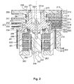
- a second embodiment of a turbomolecular pump rotor is in a section along the axis of rotation in FIG. 2 shown.
- This example relates to a turbomolecular pump equipped with active magnetic bearings.
- a safety bearing 295 surrounding the shaft 232, a safety bearing 295, a radial bearing coil 291, a radial sensor 293 and the motor coil 261 are arranged.
- the motor coil cooperates with the motor magnet 262 located on the shaft and secured by a sleeve 263, so that when the motor coil is energized, the shaft is set in rapid rotation.
- the radial sensor cooperates with the shaft-side Radialsensortarget 294 and allows a magnetic bearing control electronics, not shown, the determination of the radial deflection of the rotor and thus the control of the radial bearing coil.
- the turbomolecular pump of this example facing the fore-vacuum, has a Holweck stator 228 in which run helical channels which cooperate with the sleeve 227 arranged on the rotor and together form a Holweck stage 226.
- stator disks 212, 216, 220 and 224 provided with blade rings which are axially spaced by spacer rings 213, 217, 221 and 225 arranged between them.
- the pump structures designed as rotor blade rings 211, 215, 219 and 223 dip.
- Dormant and rotor-side pump structures interact in pairs.
- the rotor blade ring 211 together with the stator disk 212 forms the first chamber-facing and high-vacuum pumping stage 210.
- stator disk 216 and rotor blade ring 215 form the subsequent second pump stage 214, stator disk 220 and rotor blade ring 219, third pump stage 218, and finally stator disk 224 and rotor blade ring
- the rotor blade rings are each arranged in mutually axially spaced planes 250, 251, 252 and 253, the attachment region of the rotor sleeve forms the plane 254.
- the rotor-side pumping structures in the form of the rotor blade rings 219 and 223 are arranged on the first rotor part 201 and form with this a one-piece body.
- the rotor sleeve 227 is connected to the first rotor part.
- the first rotor part has a recess 230 in its center. This axially and radially extending from the center cavity takes the catch bearing at least partially, so that advantageously the overall length of the turbo pump is reduced.
- the cavity can be enlarged so that the housing part 260, which includes radial bearing, radial sensor and motor coil, over part of its axial Expansion is located in it. This leads to a further reduction in the length of the turbopump extending in the direction of the rotor axis of symmetry.
- the first rotor part is connected to a securing means, in the example of a screw 280, with the end face of the shaft 232.
- the shaft has a recess with which a pin 289 of the first rotor part is engaged, whereby the radial positioning is simplified.
- the first rotor part has a support portion 201a. This extends axially from the first rotor part in the direction of high vacuum, ie in the direction away from the shaft. On this support portion, a support ring 208 are arranged, with which the rotor blade ring 211 is connected. Another support ring 209 and the rotor blade ring 215 are also connected together.
- the support rings with rotor helix are inexpensive to produce, for example by sawing from solid material. For this purpose, inexpensive high-strength material is available.
- the separation between the first rotor part and support rings increases the burst safety, in which the tearing of the component at this separation is delayed. In addition, the maximum size of the fragments is reduced.
- a reinforcing ring 281 is provided, which is arranged so that it touches both support rings 208 and 209 on the surface and counteracts widening of the support rings in the radial direction by centrifugal forces.
- Another development provides for frontally into the carrier section 201a to provide balancing bores 270 into which balancing weights 271 are inserted can. Together with provided between the rotor blade rings 219 and 223 lower balancing bores 272 and balancing weights 273 therein as needed a very good balancing of the rotor is achieved with easy accessibility of balancing bores.
- the first rotor part can have more than two rotor blade rings, and the number of bearing rings can be increased or reduced compared to the figure.
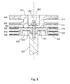
- a third embodiment of a turbomolecular pump rotor is in a section along the axis of rotation in FIG. 3 shown.
- An alternative construction of the turbomolecular pump rotor without the other components of the turbopump is shown.
- the turbomolecular pump rotor comprises a shaft 332, to whose front side a first rotor part 301 is connected.
- the shaft has a recess with which a pin 389 of the first rotor part is engaged, whereby the radial centering is effected.
- the shaft is located with a portion of its length in a cavity 330 which extends from the axis of rotation of the first rotor part over a portion of the radius and in the axial direction. This cavity receives a portion of the other components of the turbo pump, for example parts of bearing and drive, whereby the overall length of the turbo pump is reduced.
- the first rotor part has three rotor blade rings 319, 323 and 329 arranged in three planes 352, 353 and 354.
- a second rotor part 302. On the side facing away from the shaft of the first rotor part is a second rotor part 302. This is centered by centering means 382 relative to the first rotor part.
- the centering means is designed as a recess in the first rotor part, with which the second rotor part is engaged.
- the second Rotor part has a, the first rotor part facing away, high-vacuum side recess 383, in which a screw 380 is arranged, which serves the secure connection of shaft, first and second rotor part.
- the second rotor part comprises the rotor blade rings 311 and 315, which are arranged in the planes 350 and 351.
- This construction also leads to a favorable behavior in the case of a burst due to the size of the resulting fragments.
- An advantage of this arrangement is the small number of components, so that few parts are to be added.
- the starting material is cheaper than in the case of a full bell, that is, a single body, which includes all rotor blade rings.
- the number of rotor blade rings, which is arranged on each of the rotor parts, is greater than or equal to two, depending on the vacuum engineering design of the turbo pump.
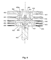
- a fourth embodiment of a turbomolecular pump rotor is in a section along the axis of rotation in FIG. 4 shown.
- An alternative construction of the turbomolecular pump rotor without the other components of the turbopump is shown.
- this turbomolecular pump rotor has a second rotor part 402 with an extension 402a.
- the support rings 408 and 409 are arranged, which are positioned for example by shrinking or clamping.
- the rotor blade ring 415 of the plane 451 is formed integrally with the support ring 409.
- the rotor blade ring 411 located in the plane 450 is designed in one piece with the support ring 408.
- the extension 402a surrounds the high-vacuum-side recess 483, in which a screw 480 is arranged.
- the first Rotor part has on its side facing the shaft on a recess 430, which space for stator components, such as bearings and engine, creates. This recess reduces the overall length of the turbo pump.
- the construction of two parts and support rings improves the behavior in case of a burst very clearly.
- Centering means are advantageous as in the third example, which ensure a safe centering of the first and second rotor part to each other.
- the structure according to this fourth example allows the design with support rings great freedom in the choice of the blade geometry of the rotor blade rings 411 and 415. In addition, a good centering of the support rings is achieved, so that the balancing behavior is improved.
- Shaft and first rotor part are centered by a pin 489 to each other, which is in engagement with an end-side recess of the shaft.
- the first rotor part can have more than two rotor blade rings, and the number of supporting rings can be increased or reduced in comparison with the figure.
- a fifth embodiment of a turbomolecular pump rotor is in a section along the axis of rotation in FIG. 5 shown.
- An alternative construction of the turbomolecular pump rotor without the other components of the turbopump is shown.
- the turbomolecular pump rotor shown in partial section has rotor blade rings 511, 515 and 519 disposed in the axially spaced planes 550, 551 and 552 and forming part of the first rotor part 501.
- Each rotor blade ring as in the previous examples, has blades which extend radially and are turned against the direction of movement.
- the first rotor part is connected by means of the screw 580 with an end face of the shaft 532. Shaft and first rotor part are centered by a pin 589 to each other, which with a frontal recess of the shaft is engaged. With the fore vacuum-side end face 586 of the first rotor part, a second rotor part 502 is connected.
- the centering of the first and second rotor part is achieved by means of a projection 597, which is in engagement with a recess of the first rotor part and located on the end face of the second rotor part.
- a reinforcing ring 581 It is arranged in a recess, so that it advantageously has no influence on the gap between the rotor and stator.
- the second rotor part comprises the pump structures arranged in the axially spaced-apart planes 553 and 554 in the form of a rotor blade ring 553 and a sleeve sleeve 584.
- the first rotor part has a recess 530 which, together with the central through hole 588 of the second rotor part, forms a large cavity for receiving Bearing and engine components of the turbo pump results.
- the turbomolecular pump rotor of this example combines a pronounced advantage of shortening the length with a very safe burst behavior, because even with this rotor, only small fragments are produced in the event of a burst.
- the number of rotor blade rings on the second rotor part can be higher and can be dispensed with as needed on the Holweckhülse. This depends on the desired vacuum data.
Landscapes
- Engineering & Computer Science (AREA)
- Mechanical Engineering (AREA)
- General Engineering & Computer Science (AREA)
- Non-Positive Displacement Air Blowers (AREA)
Applications Claiming Priority (1)
| Application Number | Priority Date | Filing Date | Title |
|---|---|---|---|
| DE102009035812A DE102009035812A1 (de) | 2009-08-01 | 2009-08-01 | Turbomolekularpumpenrotor |
Publications (3)
| Publication Number | Publication Date |
|---|---|
| EP2295813A2 true EP2295813A2 (fr) | 2011-03-16 |
| EP2295813A3 EP2295813A3 (fr) | 2015-08-19 |
| EP2295813B1 EP2295813B1 (fr) | 2019-09-18 |
Family
ID=43036975
Family Applications (1)
| Application Number | Title | Priority Date | Filing Date |
|---|---|---|---|
| EP10007376.6A Active EP2295813B1 (fr) | 2009-08-01 | 2010-07-16 | Rotor de pompe turbo-moléculaire |
Country Status (3)
| Country | Link |
|---|---|
| EP (1) | EP2295813B1 (fr) |
| JP (1) | JP2011033027A (fr) |
| DE (1) | DE102009035812A1 (fr) |
Families Citing this family (1)
| Publication number | Priority date | Publication date | Assignee | Title |
|---|---|---|---|---|
| DE102014100622A1 (de) * | 2014-01-21 | 2015-07-23 | Pfeiffer Vacuum Gmbh | Verfahren zur Herstellung einer Rotoranordnung für eine Vakuumpumpe und Rotoranordnung für eine Vakuumpumpe |
Citations (3)
| Publication number | Priority date | Publication date | Assignee | Title |
|---|---|---|---|---|
| DE1728487A1 (de) | 1962-01-23 | 1973-04-26 | Commissariat Energie Atomique | Axial durchstroemte turbomolekularpumpe |
| EP1517042A1 (fr) | 2003-09-17 | 2005-03-23 | Mecos Traxler AG | Pallier magnétique pour une pompe à vide |
| EP1559914A1 (fr) | 2004-01-29 | 2005-08-03 | Pfeiffer Vacuum GmbH | Pompe à effet visqueux |
Family Cites Families (12)
| Publication number | Priority date | Publication date | Assignee | Title |
|---|---|---|---|---|
| DE3239328C2 (de) * | 1982-10-23 | 1993-12-23 | Pfeiffer Vakuumtechnik | Magnetisch gelagerte Turbomolekularpumpe mit Schwingungsdämpfung |
| JPH0259294U (fr) * | 1988-10-25 | 1990-04-27 | ||
| DE10008691B4 (de) * | 2000-02-24 | 2017-10-26 | Pfeiffer Vacuum Gmbh | Gasreibungspumpe |
| JP3792112B2 (ja) * | 2000-09-06 | 2006-07-05 | 株式会社荏原製作所 | 真空ポンプ |
| JP3784250B2 (ja) * | 2000-11-06 | 2006-06-07 | 株式会社荏原製作所 | 真空ポンプ |
| JP2002168249A (ja) * | 2000-11-29 | 2002-06-14 | Shimadzu Corp | 回転機械 |
| GB0229355D0 (en) * | 2002-12-17 | 2003-01-22 | Boc Group Plc | Vacuum pumping arrangement |
| GB0322889D0 (en) * | 2003-09-30 | 2003-10-29 | Boc Group Plc | Vacuum pump |
| DE202005019644U1 (de) * | 2005-12-16 | 2007-04-26 | Leybold Vacuum Gmbh | Turbomolekularpumpe |
| DE102007048703A1 (de) * | 2007-10-11 | 2009-04-16 | Oerlikon Leybold Vacuum Gmbh | Mehrstufiger Turbomolekularpumpen-Pumpenrotor |
| JP5087418B2 (ja) * | 2008-02-05 | 2012-12-05 | 株式会社荏原製作所 | ターボ真空ポンプ |
| DE102008056352A1 (de) * | 2008-11-07 | 2010-05-12 | Oerlikon Leybold Vacuum Gmbh | Vakuumpumpenrotor |
-
2009
- 2009-08-01 DE DE102009035812A patent/DE102009035812A1/de not_active Ceased
-
2010
- 2010-07-16 EP EP10007376.6A patent/EP2295813B1/fr active Active
- 2010-07-27 JP JP2010167827A patent/JP2011033027A/ja active Pending
Patent Citations (3)
| Publication number | Priority date | Publication date | Assignee | Title |
|---|---|---|---|---|
| DE1728487A1 (de) | 1962-01-23 | 1973-04-26 | Commissariat Energie Atomique | Axial durchstroemte turbomolekularpumpe |
| EP1517042A1 (fr) | 2003-09-17 | 2005-03-23 | Mecos Traxler AG | Pallier magnétique pour une pompe à vide |
| EP1559914A1 (fr) | 2004-01-29 | 2005-08-03 | Pfeiffer Vacuum GmbH | Pompe à effet visqueux |
Also Published As
| Publication number | Publication date |
|---|---|
| JP2011033027A (ja) | 2011-02-17 |
| EP2295813B1 (fr) | 2019-09-18 |
| EP2295813A3 (fr) | 2015-08-19 |
| DE102009035812A1 (de) | 2011-02-03 |
Similar Documents
| Publication | Publication Date | Title |
|---|---|---|
| EP2209995B1 (fr) | Rotor de pompe à plusieurs étages pour pompes turbomoléculaires | |
| DE2534528A1 (de) | Vakuumpumpe | |
| DE2654055B2 (de) | Rotor- und Statorscheibe für Turbomolekularpumpe | |
| EP2458222B1 (fr) | Pompe turbomoléculaire | |
| EP2826999A1 (fr) | Pompe à vide | |
| DE102009021620B4 (de) | Vakuumpumpe | |
| EP2253851B1 (fr) | Pompe à vide | |
| DE3722164A1 (de) | Turbomolekularpumpe | |
| CH646229A5 (de) | Verfahren zur herstellung eines rotors mit mindestens einem schaufelkranz fuer eine turbomolekularpumpe und nach diesem verfahren hergestellter rotor. | |
| EP2290242A2 (fr) | Pompe à vide | |
| EP3670924B1 (fr) | Pompe à vide et procédé de fabrication d'une telle pompe à vide | |
| DE102011119506A1 (de) | Schnell drehender Rotor für eine Vakuumpumpe | |
| EP3091235B1 (fr) | Disque de rotor | |
| WO2003076809A1 (fr) | Procede de realisation du rotor d'une pompe a vide a frottements, et rotor produit grace a ce procede | |
| EP2295813B1 (fr) | Rotor de pompe turbo-moléculaire | |
| EP3093496B1 (fr) | Rotor pour pompe à vide | |
| EP1201928B1 (fr) | Disques pour pompe turbomoléculaire | |
| DE29715035U1 (de) | Reibungsvakuumpumpe | |
| WO2011032549A1 (fr) | Turbomachine axiale-radiale | |
| EP3734078B1 (fr) | Pompe turbomoléculaire et procédé de fabrication d'un disque de stator pour une telle pompe | |
| EP3460249B1 (fr) | Pompe à vide à debit partagé | |
| EP2913533A1 (fr) | Disque de stator | |
| EP3916235B1 (fr) | Procédé de fabrication d'une pompe à vide | |
| EP3088746B1 (fr) | Pompe à vide | |
| EP3196471B1 (fr) | Pompe a vide |
Legal Events
| Date | Code | Title | Description |
|---|---|---|---|
| PUAI | Public reference made under article 153(3) epc to a published international application that has entered the european phase |
Free format text: ORIGINAL CODE: 0009012 |
|
| AK | Designated contracting states |
Kind code of ref document: A2 Designated state(s): AL AT BE BG CH CY CZ DE DK EE ES FI FR GB GR HR HU IE IS IT LI LT LU LV MC MK MT NL NO PL PT RO SE SI SK SM TR |
|
| AX | Request for extension of the european patent |
Extension state: BA ME RS |
|
| RIC1 | Information provided on ipc code assigned before grant |
Ipc: F04D 27/00 20060101ALI20150330BHEP Ipc: F04D 19/04 20060101AFI20150330BHEP |
|
| PUAL | Search report despatched |
Free format text: ORIGINAL CODE: 0009013 |
|
| AK | Designated contracting states |
Kind code of ref document: A3 Designated state(s): AL AT BE BG CH CY CZ DE DK EE ES FI FR GB GR HR HU IE IS IT LI LT LU LV MC MK MT NL NO PL PT RO SE SI SK SM TR |
|
| AX | Request for extension of the european patent |
Extension state: BA ME RS |
|
| RIC1 | Information provided on ipc code assigned before grant |
Ipc: F04D 27/00 20060101ALI20150714BHEP Ipc: F04D 19/04 20060101AFI20150714BHEP |
|
| 17P | Request for examination filed |
Effective date: 20160218 |
|
| RBV | Designated contracting states (corrected) |
Designated state(s): AL AT BE BG CH CY CZ DE DK EE ES FI FR GB GR HR HU IE IS IT LI LT LU LV MC MK MT NL NO PL PT RO SE SI SK SM TR |
|
| STAA | Information on the status of an ep patent application or granted ep patent |
Free format text: STATUS: EXAMINATION IS IN PROGRESS |
|
| 17Q | First examination report despatched |
Effective date: 20180628 |
|
| GRAP | Despatch of communication of intention to grant a patent |
Free format text: ORIGINAL CODE: EPIDOSNIGR1 |
|
| STAA | Information on the status of an ep patent application or granted ep patent |
Free format text: STATUS: GRANT OF PATENT IS INTENDED |
|
| INTG | Intention to grant announced |
Effective date: 20190401 |
|
| GRAS | Grant fee paid |
Free format text: ORIGINAL CODE: EPIDOSNIGR3 |
|
| GRAA | (expected) grant |
Free format text: ORIGINAL CODE: 0009210 |
|
| STAA | Information on the status of an ep patent application or granted ep patent |
Free format text: STATUS: THE PATENT HAS BEEN GRANTED |
|
| AK | Designated contracting states |
Kind code of ref document: B1 Designated state(s): AL AT BE BG CH CY CZ DE DK EE ES FI FR GB GR HR HU IE IS IT LI LT LU LV MC MK MT NL NO PL PT RO SE SI SK SM TR |
|
| REG | Reference to a national code |
Ref country code: GB Ref legal event code: FG4D Free format text: NOT ENGLISH |
|
| REG | Reference to a national code |
Ref country code: CH Ref legal event code: EP |
|
| REG | Reference to a national code |
Ref country code: DE Ref legal event code: R096 Ref document number: 502010016261 Country of ref document: DE |
|
| REG | Reference to a national code |
Ref country code: AT Ref legal event code: REF Ref document number: 1181633 Country of ref document: AT Kind code of ref document: T Effective date: 20191015 |
|
| REG | Reference to a national code |
Ref country code: IE Ref legal event code: FG4D Free format text: LANGUAGE OF EP DOCUMENT: GERMAN |
|
| REG | Reference to a national code |
Ref country code: NL Ref legal event code: MP Effective date: 20190918 |
|
| PG25 | Lapsed in a contracting state [announced via postgrant information from national office to epo] |
Ref country code: SE Free format text: LAPSE BECAUSE OF FAILURE TO SUBMIT A TRANSLATION OF THE DESCRIPTION OR TO PAY THE FEE WITHIN THE PRESCRIBED TIME-LIMIT Effective date: 20190918 Ref country code: NO Free format text: LAPSE BECAUSE OF FAILURE TO SUBMIT A TRANSLATION OF THE DESCRIPTION OR TO PAY THE FEE WITHIN THE PRESCRIBED TIME-LIMIT Effective date: 20191218 Ref country code: FI Free format text: LAPSE BECAUSE OF FAILURE TO SUBMIT A TRANSLATION OF THE DESCRIPTION OR TO PAY THE FEE WITHIN THE PRESCRIBED TIME-LIMIT Effective date: 20190918 Ref country code: BG Free format text: LAPSE BECAUSE OF FAILURE TO SUBMIT A TRANSLATION OF THE DESCRIPTION OR TO PAY THE FEE WITHIN THE PRESCRIBED TIME-LIMIT Effective date: 20191218 Ref country code: HR Free format text: LAPSE BECAUSE OF FAILURE TO SUBMIT A TRANSLATION OF THE DESCRIPTION OR TO PAY THE FEE WITHIN THE PRESCRIBED TIME-LIMIT Effective date: 20190918 Ref country code: LT Free format text: LAPSE BECAUSE OF FAILURE TO SUBMIT A TRANSLATION OF THE DESCRIPTION OR TO PAY THE FEE WITHIN THE PRESCRIBED TIME-LIMIT Effective date: 20190918 |
|
| REG | Reference to a national code |
Ref country code: LT Ref legal event code: MG4D |
|
| PG25 | Lapsed in a contracting state [announced via postgrant information from national office to epo] |
Ref country code: LV Free format text: LAPSE BECAUSE OF FAILURE TO SUBMIT A TRANSLATION OF THE DESCRIPTION OR TO PAY THE FEE WITHIN THE PRESCRIBED TIME-LIMIT Effective date: 20190918 Ref country code: GR Free format text: LAPSE BECAUSE OF FAILURE TO SUBMIT A TRANSLATION OF THE DESCRIPTION OR TO PAY THE FEE WITHIN THE PRESCRIBED TIME-LIMIT Effective date: 20191219 Ref country code: AL Free format text: LAPSE BECAUSE OF FAILURE TO SUBMIT A TRANSLATION OF THE DESCRIPTION OR TO PAY THE FEE WITHIN THE PRESCRIBED TIME-LIMIT Effective date: 20190918 |
|
| PG25 | Lapsed in a contracting state [announced via postgrant information from national office to epo] |
Ref country code: PT Free format text: LAPSE BECAUSE OF FAILURE TO SUBMIT A TRANSLATION OF THE DESCRIPTION OR TO PAY THE FEE WITHIN THE PRESCRIBED TIME-LIMIT Effective date: 20200120 Ref country code: NL Free format text: LAPSE BECAUSE OF FAILURE TO SUBMIT A TRANSLATION OF THE DESCRIPTION OR TO PAY THE FEE WITHIN THE PRESCRIBED TIME-LIMIT Effective date: 20190918 Ref country code: PL Free format text: LAPSE BECAUSE OF FAILURE TO SUBMIT A TRANSLATION OF THE DESCRIPTION OR TO PAY THE FEE WITHIN THE PRESCRIBED TIME-LIMIT Effective date: 20190918 Ref country code: ES Free format text: LAPSE BECAUSE OF FAILURE TO SUBMIT A TRANSLATION OF THE DESCRIPTION OR TO PAY THE FEE WITHIN THE PRESCRIBED TIME-LIMIT Effective date: 20190918 Ref country code: RO Free format text: LAPSE BECAUSE OF FAILURE TO SUBMIT A TRANSLATION OF THE DESCRIPTION OR TO PAY THE FEE WITHIN THE PRESCRIBED TIME-LIMIT Effective date: 20190918 Ref country code: EE Free format text: LAPSE BECAUSE OF FAILURE TO SUBMIT A TRANSLATION OF THE DESCRIPTION OR TO PAY THE FEE WITHIN THE PRESCRIBED TIME-LIMIT Effective date: 20190918 |
|
| PG25 | Lapsed in a contracting state [announced via postgrant information from national office to epo] |
Ref country code: SM Free format text: LAPSE BECAUSE OF FAILURE TO SUBMIT A TRANSLATION OF THE DESCRIPTION OR TO PAY THE FEE WITHIN THE PRESCRIBED TIME-LIMIT Effective date: 20190918 Ref country code: IS Free format text: LAPSE BECAUSE OF FAILURE TO SUBMIT A TRANSLATION OF THE DESCRIPTION OR TO PAY THE FEE WITHIN THE PRESCRIBED TIME-LIMIT Effective date: 20200224 Ref country code: SK Free format text: LAPSE BECAUSE OF FAILURE TO SUBMIT A TRANSLATION OF THE DESCRIPTION OR TO PAY THE FEE WITHIN THE PRESCRIBED TIME-LIMIT Effective date: 20190918 |
|
| REG | Reference to a national code |
Ref country code: DE Ref legal event code: R097 Ref document number: 502010016261 Country of ref document: DE |
|
| PLBE | No opposition filed within time limit |
Free format text: ORIGINAL CODE: 0009261 |
|
| STAA | Information on the status of an ep patent application or granted ep patent |
Free format text: STATUS: NO OPPOSITION FILED WITHIN TIME LIMIT |
|
| PG2D | Information on lapse in contracting state deleted |
Ref country code: IS |
|
| PG25 | Lapsed in a contracting state [announced via postgrant information from national office to epo] |
Ref country code: DK Free format text: LAPSE BECAUSE OF FAILURE TO SUBMIT A TRANSLATION OF THE DESCRIPTION OR TO PAY THE FEE WITHIN THE PRESCRIBED TIME-LIMIT Effective date: 20190918 Ref country code: IS Free format text: LAPSE BECAUSE OF FAILURE TO SUBMIT A TRANSLATION OF THE DESCRIPTION OR TO PAY THE FEE WITHIN THE PRESCRIBED TIME-LIMIT Effective date: 20200119 |
|
| 26N | No opposition filed |
Effective date: 20200619 |
|
| PG25 | Lapsed in a contracting state [announced via postgrant information from national office to epo] |
Ref country code: SI Free format text: LAPSE BECAUSE OF FAILURE TO SUBMIT A TRANSLATION OF THE DESCRIPTION OR TO PAY THE FEE WITHIN THE PRESCRIBED TIME-LIMIT Effective date: 20190918 |
|
| PG25 | Lapsed in a contracting state [announced via postgrant information from national office to epo] |
Ref country code: MC Free format text: LAPSE BECAUSE OF FAILURE TO SUBMIT A TRANSLATION OF THE DESCRIPTION OR TO PAY THE FEE WITHIN THE PRESCRIBED TIME-LIMIT Effective date: 20190918 |
|
| REG | Reference to a national code |
Ref country code: CH Ref legal event code: PL |
|
| REG | Reference to a national code |
Ref country code: BE Ref legal event code: MM Effective date: 20200731 |
|
| PG25 | Lapsed in a contracting state [announced via postgrant information from national office to epo] |
Ref country code: FR Free format text: LAPSE BECAUSE OF NON-PAYMENT OF DUE FEES Effective date: 20200731 Ref country code: LU Free format text: LAPSE BECAUSE OF NON-PAYMENT OF DUE FEES Effective date: 20200716 Ref country code: CH Free format text: LAPSE BECAUSE OF NON-PAYMENT OF DUE FEES Effective date: 20200731 Ref country code: LI Free format text: LAPSE BECAUSE OF NON-PAYMENT OF DUE FEES Effective date: 20200731 |
|
| PG25 | Lapsed in a contracting state [announced via postgrant information from national office to epo] |
Ref country code: BE Free format text: LAPSE BECAUSE OF NON-PAYMENT OF DUE FEES Effective date: 20200731 |
|
| PG25 | Lapsed in a contracting state [announced via postgrant information from national office to epo] |
Ref country code: IE Free format text: LAPSE BECAUSE OF NON-PAYMENT OF DUE FEES Effective date: 20200716 |
|
| REG | Reference to a national code |
Ref country code: AT Ref legal event code: MM01 Ref document number: 1181633 Country of ref document: AT Kind code of ref document: T Effective date: 20200716 |
|
| PG25 | Lapsed in a contracting state [announced via postgrant information from national office to epo] |
Ref country code: AT Free format text: LAPSE BECAUSE OF NON-PAYMENT OF DUE FEES Effective date: 20200716 |
|
| PG25 | Lapsed in a contracting state [announced via postgrant information from national office to epo] |
Ref country code: TR Free format text: LAPSE BECAUSE OF FAILURE TO SUBMIT A TRANSLATION OF THE DESCRIPTION OR TO PAY THE FEE WITHIN THE PRESCRIBED TIME-LIMIT Effective date: 20190918 Ref country code: MT Free format text: LAPSE BECAUSE OF FAILURE TO SUBMIT A TRANSLATION OF THE DESCRIPTION OR TO PAY THE FEE WITHIN THE PRESCRIBED TIME-LIMIT Effective date: 20190918 Ref country code: CY Free format text: LAPSE BECAUSE OF FAILURE TO SUBMIT A TRANSLATION OF THE DESCRIPTION OR TO PAY THE FEE WITHIN THE PRESCRIBED TIME-LIMIT Effective date: 20190918 |
|
| PG25 | Lapsed in a contracting state [announced via postgrant information from national office to epo] |
Ref country code: MK Free format text: LAPSE BECAUSE OF FAILURE TO SUBMIT A TRANSLATION OF THE DESCRIPTION OR TO PAY THE FEE WITHIN THE PRESCRIBED TIME-LIMIT Effective date: 20190918 |
|
| PGFP | Annual fee paid to national office [announced via postgrant information from national office to epo] |
Ref country code: IT Payment date: 20250724 Year of fee payment: 16 |
|
| PGFP | Annual fee paid to national office [announced via postgrant information from national office to epo] |
Ref country code: GB Payment date: 20250722 Year of fee payment: 16 |
|
| PGFP | Annual fee paid to national office [announced via postgrant information from national office to epo] |
Ref country code: CZ Payment date: 20250708 Year of fee payment: 16 |
|
| PGFP | Annual fee paid to national office [announced via postgrant information from national office to epo] |
Ref country code: DE Payment date: 20250926 Year of fee payment: 16 |