EP2343144A1 - Sécurité anti-extraction d'outils de porte-outils munis d'un attachement d'outil - Google Patents
Sécurité anti-extraction d'outils de porte-outils munis d'un attachement d'outil Download PDFInfo
- Publication number
- EP2343144A1 EP2343144A1 EP11158389A EP11158389A EP2343144A1 EP 2343144 A1 EP2343144 A1 EP 2343144A1 EP 11158389 A EP11158389 A EP 11158389A EP 11158389 A EP11158389 A EP 11158389A EP 2343144 A1 EP2343144 A1 EP 2343144A1
- Authority
- EP
- European Patent Office
- Prior art keywords
- tool
- tool holder
- holder according
- locking
- chuck
- Prior art date
- Legal status (The legal status is an assumption and is not a legal conclusion. Google has not performed a legal analysis and makes no representation as to the accuracy of the status listed.)
- Granted
Links
Images


Classifications
-
- B—PERFORMING OPERATIONS; TRANSPORTING
- B23—MACHINE TOOLS; METAL-WORKING NOT OTHERWISE PROVIDED FOR
- B23B—TURNING; BORING
- B23B31/00—Chucks; Expansion mandrels; Adaptations thereof for remote control
- B23B31/02—Chucks
- B23B31/10—Chucks characterised by the retaining or gripping devices or their immediate operating means
-
- B—PERFORMING OPERATIONS; TRANSPORTING
- B23—MACHINE TOOLS; METAL-WORKING NOT OTHERWISE PROVIDED FOR
- B23B—TURNING; BORING
- B23B31/00—Chucks; Expansion mandrels; Adaptations thereof for remote control
- B23B31/005—Cylindrical shanks of tools
-
- B—PERFORMING OPERATIONS; TRANSPORTING
- B23—MACHINE TOOLS; METAL-WORKING NOT OTHERWISE PROVIDED FOR
- B23B—TURNING; BORING
- B23B31/00—Chucks; Expansion mandrels; Adaptations thereof for remote control
- B23B31/02—Chucks
- B23B31/10—Chucks characterised by the retaining or gripping devices or their immediate operating means
- B23B31/107—Retention by laterally-acting detents, e.g. pins, screws, wedges; Retention by loose elements, e.g. balls
- B23B31/1072—Retention by axially or circumferentially oriented cylindrical elements
-
- B—PERFORMING OPERATIONS; TRANSPORTING
- B23—MACHINE TOOLS; METAL-WORKING NOT OTHERWISE PROVIDED FOR
- B23B—TURNING; BORING
- B23B31/00—Chucks; Expansion mandrels; Adaptations thereof for remote control
- B23B31/02—Chucks
- B23B31/10—Chucks characterised by the retaining or gripping devices or their immediate operating means
- B23B31/107—Retention by laterally-acting detents, e.g. pins, screws, wedges; Retention by loose elements, e.g. balls
- B23B31/1071—Retention by balls
-
- B—PERFORMING OPERATIONS; TRANSPORTING
- B23—MACHINE TOOLS; METAL-WORKING NOT OTHERWISE PROVIDED FOR
- B23B—TURNING; BORING
- B23B31/00—Chucks; Expansion mandrels; Adaptations thereof for remote control
- B23B31/02—Chucks
- B23B31/10—Chucks characterised by the retaining or gripping devices or their immediate operating means
- B23B31/117—Retention by friction only, e.g. using springs, resilient sleeves, tapers
- B23B31/1175—Retention by friction only, e.g. using springs, resilient sleeves, tapers using elastomer rings or sleeves
-
- B—PERFORMING OPERATIONS; TRANSPORTING
- B23—MACHINE TOOLS; METAL-WORKING NOT OTHERWISE PROVIDED FOR
- B23B—TURNING; BORING
- B23B31/00—Chucks; Expansion mandrels; Adaptations thereof for remote control
- B23B31/02—Chucks
- B23B31/10—Chucks characterised by the retaining or gripping devices or their immediate operating means
- B23B31/117—Retention by friction only, e.g. using springs, resilient sleeves, tapers
- B23B31/1179—Retention by friction only, e.g. using springs, resilient sleeves, tapers using heating and cooling
-
- B—PERFORMING OPERATIONS; TRANSPORTING
- B23—MACHINE TOOLS; METAL-WORKING NOT OTHERWISE PROVIDED FOR
- B23B—TURNING; BORING
- B23B31/00—Chucks; Expansion mandrels; Adaptations thereof for remote control
- B23B31/40—Expansion mandrels
-
- B—PERFORMING OPERATIONS; TRANSPORTING
- B24—GRINDING; POLISHING
- B24B—MACHINES, DEVICES, OR PROCESSES FOR GRINDING OR POLISHING; DRESSING OR CONDITIONING OF ABRADING SURFACES; FEEDING OF GRINDING, POLISHING, OR LAPPING AGENTS
- B24B45/00—Means for securing grinding wheels on rotary arbors
- B24B45/006—Quick mount and release means for disc-like wheels, e.g. on power tools
-
- B—PERFORMING OPERATIONS; TRANSPORTING
- B23—MACHINE TOOLS; METAL-WORKING NOT OTHERWISE PROVIDED FOR
- B23B—TURNING; BORING
- B23B2231/00—Details of chucks, toolholder shanks or tool shanks
- B23B2231/02—Features of shanks of tools not relating to the operation performed by the tool
- B23B2231/026—Grooves
-
- B—PERFORMING OPERATIONS; TRANSPORTING
- B23—MACHINE TOOLS; METAL-WORKING NOT OTHERWISE PROVIDED FOR
- B23B—TURNING; BORING
- B23B2231/00—Details of chucks, toolholder shanks or tool shanks
- B23B2231/04—Adapters
-
- B—PERFORMING OPERATIONS; TRANSPORTING
- B23—MACHINE TOOLS; METAL-WORKING NOT OTHERWISE PROVIDED FOR
- B23B—TURNING; BORING
- B23B2240/00—Details of connections of tools or workpieces
- B23B2240/04—Bayonet connections
-
- B—PERFORMING OPERATIONS; TRANSPORTING
- B23—MACHINE TOOLS; METAL-WORKING NOT OTHERWISE PROVIDED FOR
- B23B—TURNING; BORING
- B23B2260/00—Details of constructional elements
- B23B2260/042—Collets of known configuration, i.e. devices using a collet
-
- B—PERFORMING OPERATIONS; TRANSPORTING
- B23—MACHINE TOOLS; METAL-WORKING NOT OTHERWISE PROVIDED FOR
- B23B—TURNING; BORING
- B23B2260/00—Details of constructional elements
- B23B2260/138—Screw threads
-
- Y—GENERAL TAGGING OF NEW TECHNOLOGICAL DEVELOPMENTS; GENERAL TAGGING OF CROSS-SECTIONAL TECHNOLOGIES SPANNING OVER SEVERAL SECTIONS OF THE IPC; TECHNICAL SUBJECTS COVERED BY FORMER USPC CROSS-REFERENCE ART COLLECTIONS [XRACs] AND DIGESTS
- Y10—TECHNICAL SUBJECTS COVERED BY FORMER USPC
- Y10T—TECHNICAL SUBJECTS COVERED BY FORMER US CLASSIFICATION
- Y10T279/00—Chucks or sockets
- Y10T279/10—Expanding
- Y10T279/1021—Fluid-pressure actuator
-
- Y—GENERAL TAGGING OF NEW TECHNOLOGICAL DEVELOPMENTS; GENERAL TAGGING OF CROSS-SECTIONAL TECHNOLOGIES SPANNING OVER SEVERAL SECTIONS OF THE IPC; TECHNICAL SUBJECTS COVERED BY FORMER USPC CROSS-REFERENCE ART COLLECTIONS [XRACs] AND DIGESTS
- Y10—TECHNICAL SUBJECTS COVERED BY FORMER USPC
- Y10T—TECHNICAL SUBJECTS COVERED BY FORMER US CLASSIFICATION
- Y10T279/00—Chucks or sockets
- Y10T279/17—Socket type
- Y10T279/17291—Resilient split socket
- Y10T279/17316—Unitary
-
- Y—GENERAL TAGGING OF NEW TECHNOLOGICAL DEVELOPMENTS; GENERAL TAGGING OF CROSS-SECTIONAL TECHNOLOGIES SPANNING OVER SEVERAL SECTIONS OF THE IPC; TECHNICAL SUBJECTS COVERED BY FORMER USPC CROSS-REFERENCE ART COLLECTIONS [XRACs] AND DIGESTS
- Y10—TECHNICAL SUBJECTS COVERED BY FORMER USPC
- Y10T—TECHNICAL SUBJECTS COVERED BY FORMER US CLASSIFICATION
- Y10T279/00—Chucks or sockets
- Y10T279/17—Socket type
- Y10T279/17888—Tang offset within socket
-
- Y—GENERAL TAGGING OF NEW TECHNOLOGICAL DEVELOPMENTS; GENERAL TAGGING OF CROSS-SECTIONAL TECHNOLOGIES SPANNING OVER SEVERAL SECTIONS OF THE IPC; TECHNICAL SUBJECTS COVERED BY FORMER USPC CROSS-REFERENCE ART COLLECTIONS [XRACs] AND DIGESTS
- Y10—TECHNICAL SUBJECTS COVERED BY FORMER USPC
- Y10T—TECHNICAL SUBJECTS COVERED BY FORMER US CLASSIFICATION
- Y10T279/00—Chucks or sockets
- Y10T279/17—Socket type
- Y10T279/17897—Tang offset without socket
-
- Y—GENERAL TAGGING OF NEW TECHNOLOGICAL DEVELOPMENTS; GENERAL TAGGING OF CROSS-SECTIONAL TECHNOLOGIES SPANNING OVER SEVERAL SECTIONS OF THE IPC; TECHNICAL SUBJECTS COVERED BY FORMER USPC CROSS-REFERENCE ART COLLECTIONS [XRACs] AND DIGESTS
- Y10—TECHNICAL SUBJECTS COVERED BY FORMER USPC
- Y10T—TECHNICAL SUBJECTS COVERED BY FORMER US CLASSIFICATION
- Y10T279/00—Chucks or sockets
- Y10T279/17—Socket type
- Y10T279/17923—Transverse pin
-
- Y—GENERAL TAGGING OF NEW TECHNOLOGICAL DEVELOPMENTS; GENERAL TAGGING OF CROSS-SECTIONAL TECHNOLOGIES SPANNING OVER SEVERAL SECTIONS OF THE IPC; TECHNICAL SUBJECTS COVERED BY FORMER USPC CROSS-REFERENCE ART COLLECTIONS [XRACs] AND DIGESTS
- Y10—TECHNICAL SUBJECTS COVERED BY FORMER USPC
- Y10T—TECHNICAL SUBJECTS COVERED BY FORMER US CLASSIFICATION
- Y10T408/00—Cutting by use of rotating axially moving tool
- Y10T408/89—Tool or Tool with support
- Y10T408/907—Tool or Tool with support including detailed shank
-
- Y—GENERAL TAGGING OF NEW TECHNOLOGICAL DEVELOPMENTS; GENERAL TAGGING OF CROSS-SECTIONAL TECHNOLOGIES SPANNING OVER SEVERAL SECTIONS OF THE IPC; TECHNICAL SUBJECTS COVERED BY FORMER USPC CROSS-REFERENCE ART COLLECTIONS [XRACs] AND DIGESTS
- Y10—TECHNICAL SUBJECTS COVERED BY FORMER USPC
- Y10T—TECHNICAL SUBJECTS COVERED BY FORMER US CLASSIFICATION
- Y10T408/00—Cutting by use of rotating axially moving tool
- Y10T408/94—Tool-support
- Y10T408/95—Tool-support with tool-retaining means
-
- Y—GENERAL TAGGING OF NEW TECHNOLOGICAL DEVELOPMENTS; GENERAL TAGGING OF CROSS-SECTIONAL TECHNOLOGIES SPANNING OVER SEVERAL SECTIONS OF THE IPC; TECHNICAL SUBJECTS COVERED BY FORMER USPC CROSS-REFERENCE ART COLLECTIONS [XRACs] AND DIGESTS
- Y10—TECHNICAL SUBJECTS COVERED BY FORMER USPC
- Y10T—TECHNICAL SUBJECTS COVERED BY FORMER US CLASSIFICATION
- Y10T409/00—Gear cutting, milling, or planing
- Y10T409/30—Milling
- Y10T409/30952—Milling with cutter holder
Definitions
- the present invention relates to tool holders with a tool holder, in particular shrink chucks and other chucks for receiving rotary tools according to the preamble of claim 1.
- the object of the present invention is therefore to provide a tool holder with a chuck, in particular a shrink chuck or dg1: in which an axial migration of the rotary tool, such as round drills, profile drills, screw drills including taps, countersinks, cutters, etc., does not occur during operation is possible, but the rotary tool is held both torque-resistant and axially with respect to the axis of rotation without emigrating.
- the rotary tool is held both torque-resistant and axially with respect to the axis of rotation without emigrating.
- a tool holder according to the invention has a pull-out protection of the tool, which prevents axial migration of the tool from the tool holder.
- the pull-out securing device comprises at least one locking element and at least one corresponding thereto and the locking element receiving locking groove, which cooperate positively.
- the blocking element and the locking groove are formed at least teilkugelkopfartig, wherein either the chuck, the locking elements and the tool has the locking groove or vice versa.
- the Sperrnute which are either frontally beginning on the tool shank or in the tool holder, extended respect. The groove width to be executed, so as to allow easier insertion of the tool in the tool holder.
- the tool holder on the tool holder side has at least two rotatably mounted balls, with at least two locking grooves corresponding to the balls cooperating on the rotary tool shaft in a form-fitting manner on the rotational tool side.
- the two locking grooves are preferably threaded on the cylindrical tool shaft, starting at the end face of the cylinder shaft along the peripheral surface of the cylinder shaft arranged. This lying on the peripheral surface of the cylinder shaft of the rotary tool locking grooves are left-wrenching tools left-hand and right-handed in right-handed rotation tools before.
- the locking grooves can also be formed axially and thus parallel to the axis of rotation, whereby this still acts as a rotation for the tool.
- the induction coil is first switched on the shrink chuck, ie the induction coil is under High frequency alternating current set. Due to the occurring eddy currents in the sleeve portion of the tool holder, produced by induction from the coil surrounding the tool holder, the sleeve portion is heated rapidly, so that it expands thermally and so the inner diameter of the receiving opening is increased. The rotary tool can now be inserted into the receiving opening on the shank side.
- the end face of the rotary tool passes to the projecting into the interior of the receiving opening balls and suggests there.
- this is now turned to the left or right with respect to the axis of rotation, so that the balls can engage in the spherical grooves.
- the further rotation now forces a helical screwing and thus an axial retraction movement of the rotary tool in the shrink chuck or the like., Stops until the end face of the cylindrical shaft in the chuck or until the balls have reached their final position in the spherical locking grooves.
- the induction coil can now be switched off.
- This axial locking can only be canceled by the rotary tool is rotated in the opposite direction to the working direction of rotation of the rotary tool while it is pulled out of the chuck.
- a rotation performed counter to the working direction of the rotary tool is not possible during operation, ie during the machining of a workpiece by the rotary tool.
- this rotational movement due to the torque-tight interference fit during operation is also not possible.
- the rotary tool can not axially move out of the shrink chuck or the like.
- the machining remains accurate and dimensional accuracy can be maintained within the required tolerances. Since axial migration is avoided by the present invention, it is thus possible to produce efficiently and cost-effectively, since very little waste is produced in comparison to conventional toolholders with chucks. This also excludes another accident source and thus the risk of accidents for the machine operator.
- balls and cylindrical pins can be used with a partial or hemisphere on one of the end faces.
- These are instead of the balls in the bearing bore, which, for example, either require an outwardly projecting projection, so that the cylinder pin does not fall into the interior of the receiving opening, or an external thread, which is corresponding to the réellegwinde the bearing bore.
- the use of balls has the advantage over the use of dowel head hemispheres in that the insertion of the rotary tool is easier compared to dowel pins since the balls are rotatably mounted and can not be misjudged compared to the cylindrical shank.
- balls can be held in the respective bearing bore using a threaded pin.
- the cylinder pin itself on its front side on a ball receiving training, for example.
- a ball receiving training for example.
- the cylinder pin itself on its front side on a ball receiving training, for example.
- the cylinder pin In the form of a polygonal recess or a spherical indentation o. The like ..
- the threaded pin and dowel pins o. The like. Can be used.
- the extract safety of tools according to the invention is particularly suitable for chucks, such as collet chuck, HG chuck, hydraulic chuck and shrink chuck.
- the Sperrnute are formed differently depending on the requirement in the peripheral surfaces of the shaft of the tool.
- the Sperrnute may have from the front side of a different Sperrnutverlauf.
- This one can be helical, L-shaped, curved or formed from composite sectionally straight and / or curved cylindrical surface paths.
- the direction of rotation must correspond to the direction of rotation of the grooved tool. Ie. if the tool has been grooved to the left, the helical locking groove must be on the left rising, and on the right grooved tool, on the other hand, it must be right-angled. Therefore, there is also a blocking effect of the pull-out protection.
- the shank of the tool has an external thread on the end side and the tool holder of the tool holder has a corresponding internal thread.
- the pull-out protection is carried out using the external thread on the tool, which is formed on the left-hand side with left-grooved tool and the right-hand with right-hand grooved tool.
- locking elements and locking grooves become obsolete.
- the bearing bores which receive the locking elements are preferably formed continuously from the outer peripheral surface of the tool holder to the interior of the tool holder receiving into the tool.
- these bearing bores may be formed to be cutting perpendicular to the axis of rotation of the tool holder and the axis of rotation and / or be formed tangentially adjacent to the inner peripheral surface of the tool receiving interior.
- the longitudinal axes of the bearing bores are mutually equiangular and in particular arranged in a plane perpendicular to the axis of rotation of the tool.
- the balls are mounted as locking elements in a ball cage.
- the bearing bores for the respective balls in the ball cage with respect to the inner peripheral surface each have a smaller bore diameter than the bearing bore diameter.
- the ball cage can either be inserted positively as a separate component in the interior of the tool holder, or be incorporated in a sleeve.
- the sleeve has the respective bearing bores with respect to the interior lying smaller bearing bore diameters.
- the sleeve can be pressed into the interior of the tool holder, shrunk, welded to the tool holder, positively held with additional threaded pins and / or with locking elements and locking grooves on the sleeve, as described according to the invention were described on the shaft of rotary tools.
- the pull-out protection additionally has a device which enables a play-free holding of the tool with the safety catch.
- the tool is pressed in the direction of the tool holder in the direction of the tool holder by a force exerting element, which is, for example. Concentric to the axis of rotation of the tool at the bottom of the hole.
- the pull-out protection is free of play on the tool.
- the tool allows a certain freedom of movement, which can already lead to damage to the tool cutting.
- compression springs in the form of coil springs, conical springs, disc springs and disc spring assemblies and / or elastic or rubber-elastic elements are possible.
- this has at least one transfer piece for the minimum quantity lubrication that comprises at least one, preferably a plurality of channels for the pressure build-up or pressure compensation.
- the transfer piece preferably in the form of a tube, which can also be composed of several parts, is preferably formed with a radial flange and preferably movably received and guided in a bore located in the tool holder.
- the tube which may also have different cross-sectional profiles, is preferably biased by a coil spring mounted in the tool holder, wherein the cylindrical shaft of the tube preferably penetrates the coil spring.
- a coil spring mounted in the tool holder, wherein the cylindrical shaft of the tube preferably penetrates the coil spring.
- Other force-exerting elements such as tension spring, conical spring, disc spring, and / or elastic elements and combinations thereof are possible.
- the spiral spring is preferably arranged between the radial flange of the tube and, for example, a stop bottom in the tool holder, whereby the tube is mounted biased relative to the tool holder.
- the transfer piece is preferably sealed in the bore.
- the tool holder concentric with the bore for the transfer piece or pipe, for example, at least one shaft seal and / or other sealing elements such as sealing rings, sealing lips, etc., which may also be arranged in the tool holder and / or on the transfer piece or on the pipe itself.
- the channels in the form of through holes are preferably arranged in the radial flange of the transfer piece, so that the through hole in the transfer piece are connected to the through hole in the radial flange of the transfer piece.
- a radial recess is arranged along the cylindrical peripheral surface of the radial flange of the transfer piece.
- both the members vomausdorfminausEnglishung in particular in the form of a groove, as well as the preferably corresponding cross-section of the membrane embedded in the groove, for example.
- the ring membrane is preferably formed of an elastic material, in particular of a rubber-elastic material, but other materials are possible, such as carbon fiber material, plastics, Teflon and flexible metals.
- the channels for the pressure equalization or pressure build-up are in particular connected to the membrane and the interior of the transfer piece. In a pressure build-up in the tool holder, the diaphragm therefore bulges radially and thus abuts against the peripheral surface of the receiving bore of the tool holder. As a result, the transfer piece is locked against axial adjustment.
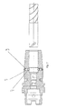
- Fig. 1 shows schematically in a sectional view the tool holder 1 and, by way of example, an end mill 2, which are arranged relative to one another with respect to a rotation axis 3.
- the tool holder 1 has at least two, preferably three or four balls 4.
- the ball is located in a bearing bore 5, which is perpendicular to the axis of rotation 3 and thus to the longitudinal axis, in the sleeve portion 6 of the tool holder 1 is arranged.
- This bearing bore 5 is a through hole and extends from the outside of the sleeve portion 6 to the inner peripheral surface receiving opening 7, which is arranged concentrically to the rotation axis 3 in the tool holder 1.
- the bearing front 8 of the bearing bore 5 is formed in the form of a spherical shell and according to the spherical shape of the ball 4, so that the ball 4 protrudes partially into the interior of the receiving opening 7.
- the ball 4 is by a threaded pin 9 in its forward position, ie in one of the interior held the receiving opening 7 projecting position, while the bearing bore 5 has a corresponding to the external thread of the threaded pin 9 internal thread.
- the length of the threaded pin 9 does not protrude beyond the outer surface of the sleeve portion 6.
- the threaded pin 9 in this case has a hexagon socket 10.
- the end mill 2 has on its cylindrical shaft 11 in the vicinity of the end face 12, the helically arranged locking grooves 13, 14.
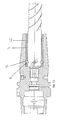
- Fig. 2 shows purely schematically in a sectional view of the tool holder 1, in which the end mill 2 is completely clamped.
- the end mill 2 is located up to its stop with its cylindrical shank 11 in the receiving opening 7.
- the ball 4 held by the threaded pin 9 engages in the locking groove 13 and 14.
- the induction coil (not shown in the drawing) is turned off and the shrinkage chuck of the tool holder 1 is cooled and shrunk back to its original size.
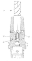
- Fig. 3 shows a schematic sectional view of a conventional collet chuck with union nut with the pull-out protection according to the invention by the Sperrnute and balls.
- Fig. 4 shows a HG-lining with the pull-out protection according to the invention by Sperrnute and balls.
- Fig. 5 shows in a purely schematic sectional view of an ordinary Hydraulic expansion chuck with inventive pull-out protection through the Sperrnute and balls.
- Fig. 6 shows in a purely schematic sectional view of a tool holder in the form of a shrink chuck, wherein the end mill with the tool via a thread 16 is screwed together. Due to this screwing, which is formed rising left in left-grooved tool and right rising in neurosciencegenutetem tool, an axial pull-out protection of the tool is achieved from the tool holder.
- Fig. 7 shows in a purely schematic sectional view of a shrink chuck with locking elements in the form of balls 4, which are held in the respective bearing bores 5 with grub screws 9.
- the threaded pin 9 has a blunt end face.
- Fig. 8 shows in a purely schematic sectional view of a shrink chuck with locking elements in the form of balls 4, which are held in the bearing bores 5 by threaded pins 9.
- Grub screw 9 has at the ball 4 receiving end side a recess 17.
- the recess 17 is formed in the form of a blind hole or, for example, in the form of a hexagon socket corresponding to the diameter of the ball.
- Fig. 9 shows in a purely schematic sectional view of a shrink chuck with locking elements in the form of balls 4, which are held in the bearing bores 5 by passport 18. Due to the interference fit between the dowel pin 18 and the bearing bore 5, the locking elements in the form of balls 4 are fixed in position.
- Fig. 10 shows in a purely schematic sectional view of a shrink chuck with one-piece locking elements 19.
- Locking element 19 is a threaded pin, which has a hemisphere head 20 at one of its end faces.
- Fig. 11 shows in a purely schematic sectional view of a shrink chuck with one-piece locking element 19 in the bearing bores 5.
- the one-piece locking elements 19 are dowel pins, which are connected in press-fit with the shrink chuck.
- the one-piece locking elements 19 have a hemisphere head 20 on one of their end faces.
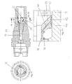
- Fig. 12 shows in a purely schematic sectional view of a shrink chuck with locking elements in the form of balls 4.
- the balls 4 are mounted in a ball cage 21.
- the ball cage 21 is arranged on the opening bottom of the receiving opening 7.
- Adjacent thereto is a sleeve 22.
- the balls 4 are inserted, which are radially from the cage be pushed outward.
- the balls 4 are pressed against a shoulder which is located between the receiving opening 7 and a free rotation at the end of the receiving opening 7. At this shoulder, the balls 4 can be supported axially.
- the balls 4 are also supported inwards and can thus secure both the tool 2 and the sleeve 22 against axial withdrawal.
- Fig. 13 shows in a purely schematic sectional view of a shrink chuck with the balls 4, which are located in a sleeve 22 in the left portion of the sleeve and in the receiving opening 7.
- the left portion of the sleeve 22, in this case acts as a ball cage for the balls 4.
- the bearing bores 5 for the balls 4 in the sleeve 22 have respect.
- the inner cylindrical peripheral surface of the sleeve 22 has a smaller diameter than the diameter of the balls or the bearing bore diameter.
- the sleeve 22 is either shrunk or pressed into the lining.
- Fig. 14 shows in a purely schematic sectional view of a shrink chuck with balls 4 in a sleeve 22.
- the sleeve 22 is connected to the sleeve portion 6 with a weld 23.
- the welding of the sleeve 22 with the shrink chuck can be formed selectively, in sections or in a ring shape as a closed, for example Y-seam.
- Fig. 15 shows in a purely schematic sectional view of a shrink chuck with balls 4 in a sleeve 22.
- the sleeve 22 is fixed by means of threaded pins 24 with the tool holder.
- the sleeve 22 has corresponding recesses 25, which correspond to the end-side tip formation of the set screws 24 are formed. In the present embodiment, these depressions 25 are formed in a cone shape.
- three, more preferably four setscrews for fixing the sleeve 22 are arranged on the tool holder.
- Fig. 16 shows in a purely schematic sectional view of a shrink chuck with the arranged in the sleeve 22 locking elements in the form of balls 4.
- the sleeve 22 is formed thick-walled, as in the previous figures. Therefore, the sleeve 22 is slotted (not shown in the drawing).
- the sleeve 22 is also connected by balls with the tool holder. There are in the left of the Sleeve 22 corresponding to the balls locking groove 27, which also have a ball profile.
- the sleeve 22 is fixed axially via balls 26 as locking elements with locking grooves 27 in the outer peripheral surface of the sleeve 22.
- the balls 26 are located in bearing bores 28, which in turn connects threaded pins 29 with a thread. Also in this case, the bearing bore 28 in the inner region in the direction of the receiving opening 7 has a smaller diameter than the bearing diameter, which corresponds to the ball diameter of the ball 26. Thus, the ball 26 does not fall into the interior, but they protrude.
- Fig. 17 shows in a purely schematic sectional view of a shrink chuck with an axial pull-out protection according to Fig. 2
- the tool holder has a conical spring 30, which is located between the end face 12 of the cylindrical shaft 11 of the end mill 2 and the bottom 31 of the receiving opening 7.
- the compression spring in the form of a conical spring 30 presses on the end face 12 of the end mill 2 in the direction of the axis of rotation 3 from the tool holder 1 addition, thus a possible clearance or manufacturing tolerances of Sperrnute in the peripheral surface of the cylinder shaft 11 and the respective position of the balls 4 in Tool holder 1 is eliminated, in that the end mill 2 is additionally locked in the axial direction by the force of the conical spring 3.
- a small clearance between the axial safety catch and the tool can be eliminated.
- Fig. 18 shows in a purely schematic sectional view of a shrink chuck with the locking elements in the form of balls 4.
- a length adjustment screw 32 which is preferably formed of a rubber-elastic material.
- an internal thread 33 is formed in the tool holder corresponding.
- the locking groove 34 in the form of an "L"'s, but beginning of the end face 12 of the cylinder shaft 11, formed. This is a quasi bayonet-like lock for axial blocking as a pull-out protection of the tool created from the tool holder.
- Fig. 19 shows in a purely schematic sectional view of a shrink chuck Fig. 18 , wherein an elastic element 35 integrated therein is arranged concentrically to the length adjustment screw 32.
- the elastic member 35 is preferably one formed rubber-elastic material. The play-safe pull-out protection takes place via the contact force which is exerted on the elastic element 35 via the end face 12 on the end mill 2 via the length adjustment screw 32.
- Fig. 20 shows in a purely schematic sectional view of a shrink chuck, with a minimum quantity lubrication (MQL).
- MQL minimum quantity lubrication
- the axial pull-out lock takes place via locking elements 36, which in turn are formed in the form of balls.
- Concentric with the axis of rotation inside the shrink chuck is a slidable tube 37, which is the transfer piece for minimum quantity lubrication.
- the tube 37 is pressed due to the spring force of a coil spring 38 to the tool shank (not shown in the drawing).
- two possible end positions of the tube 37 are shown.
- the right-lying contact surface of the tube with the tool shank is conically shaped in the form of a radial tube flange 39.
- the membrane bulges radially, thus laying against the inner peripheral surface of the receiving opening 7 of the tool holder.
- the tube 37 is secured as a transfer piece for the minimum quantity lubrication against axial displacement. Through the sliding tube 37, the grease mist can be passed lossless to the tool.
Landscapes
- Engineering & Computer Science (AREA)
- Mechanical Engineering (AREA)
- Gripping On Spindles (AREA)
- Finish Polishing, Edge Sharpening, And Grinding By Specific Grinding Devices (AREA)
- Jigs For Machine Tools (AREA)
- Manipulator (AREA)
- Automatic Tool Replacement In Machine Tools (AREA)
- Blast Furnaces (AREA)
Priority Applications (3)
| Application Number | Priority Date | Filing Date | Title |
|---|---|---|---|
| EP18192952.2A EP3427874B1 (fr) | 2006-04-10 | 2007-04-05 | Système composé d'un porte-outil et d'un outil muni d'une protection amovible |
| PL11158389.4T PL2343144T5 (pl) | 2006-04-10 | 2007-04-05 | Zabezpieczenie przed wysunięciem narzędzi z uchwytów narzędziowych za pomocą uchwytu mocującego narzędzie |
| EP17195584.2A EP3300822B1 (fr) | 2006-04-10 | 2007-04-05 | Sécurité anti-extraction d'outils de porte-outils munis d'un attachement d'outil |
Applications Claiming Priority (4)
| Application Number | Priority Date | Filing Date | Title |
|---|---|---|---|
| DE102006016784 | 2006-04-10 | ||
| DE102006028408A DE102006028408A1 (de) | 2006-04-10 | 2006-06-19 | Auszugssicherung von Werkzeugen aus Werkzeughaltern mit einer Werkzeugaufnahme |
| EP07724059A EP2004351B1 (fr) | 2006-04-10 | 2007-04-05 | Securite anti-extraction d'outils de porte-outils munis d'un attachement d'outil |
| PCT/EP2007/003118 WO2007118626A1 (fr) | 2006-04-10 | 2007-04-05 | Sécurité anti-extraction d'outils de porte-outils munis d'un attachement d'outil |
Related Parent Applications (2)
| Application Number | Title | Priority Date | Filing Date |
|---|---|---|---|
| EP07724059.6 Division | 2007-04-05 | ||
| EP07724059A Division EP2004351B1 (fr) | 2006-04-10 | 2007-04-05 | Securite anti-extraction d'outils de porte-outils munis d'un attachement d'outil |
Related Child Applications (4)
| Application Number | Title | Priority Date | Filing Date |
|---|---|---|---|
| EP18192952.2A Division EP3427874B1 (fr) | 2006-04-10 | 2007-04-05 | Système composé d'un porte-outil et d'un outil muni d'une protection amovible |
| EP18192952.2A Division-Into EP3427874B1 (fr) | 2006-04-10 | 2007-04-05 | Système composé d'un porte-outil et d'un outil muni d'une protection amovible |
| EP17195584.2A Division EP3300822B1 (fr) | 2006-04-10 | 2007-04-05 | Sécurité anti-extraction d'outils de porte-outils munis d'un attachement d'outil |
| EP17195584.2A Division-Into EP3300822B1 (fr) | 2006-04-10 | 2007-04-05 | Sécurité anti-extraction d'outils de porte-outils munis d'un attachement d'outil |
Publications (3)
| Publication Number | Publication Date |
|---|---|
| EP2343144A1 true EP2343144A1 (fr) | 2011-07-13 |
| EP2343144B1 EP2343144B1 (fr) | 2019-01-09 |
| EP2343144B2 EP2343144B2 (fr) | 2024-09-04 |
Family
ID=38542456
Family Applications (4)
| Application Number | Title | Priority Date | Filing Date |
|---|---|---|---|
| EP18192952.2A Active EP3427874B1 (fr) | 2006-04-10 | 2007-04-05 | Système composé d'un porte-outil et d'un outil muni d'une protection amovible |
| EP11158389.4A Active EP2343144B2 (fr) | 2006-04-10 | 2007-04-05 | Securité anti-extraction d'outils de porte-outils munis d'un attachement d'outil |
| EP17195584.2A Active EP3300822B1 (fr) | 2006-04-10 | 2007-04-05 | Sécurité anti-extraction d'outils de porte-outils munis d'un attachement d'outil |
| EP07724059A Active EP2004351B1 (fr) | 2006-04-10 | 2007-04-05 | Securite anti-extraction d'outils de porte-outils munis d'un attachement d'outil |
Family Applications Before (1)
| Application Number | Title | Priority Date | Filing Date |
|---|---|---|---|
| EP18192952.2A Active EP3427874B1 (fr) | 2006-04-10 | 2007-04-05 | Système composé d'un porte-outil et d'un outil muni d'une protection amovible |
Family Applications After (2)
| Application Number | Title | Priority Date | Filing Date |
|---|---|---|---|
| EP17195584.2A Active EP3300822B1 (fr) | 2006-04-10 | 2007-04-05 | Sécurité anti-extraction d'outils de porte-outils munis d'un attachement d'outil |
| EP07724059A Active EP2004351B1 (fr) | 2006-04-10 | 2007-04-05 | Securite anti-extraction d'outils de porte-outils munis d'un attachement d'outil |
Country Status (19)
| Country | Link |
|---|---|
| US (3) | US8505893B2 (fr) |
| EP (4) | EP3427874B1 (fr) |
| JP (5) | JP5240582B2 (fr) |
| KR (1) | KR101378561B1 (fr) |
| CN (2) | CN105057722B (fr) |
| AT (1) | ATE516097T1 (fr) |
| BR (1) | BRPI0710709B1 (fr) |
| CA (1) | CA2647929C (fr) |
| DE (9) | DE102006062973C5 (fr) |
| DK (1) | DK2004351T3 (fr) |
| EG (1) | EG25403A (fr) |
| ES (2) | ES2369193T3 (fr) |
| IL (1) | IL194405A (fr) |
| MX (1) | MX2008013019A (fr) |
| MY (1) | MY160425A (fr) |
| PL (2) | PL2343144T5 (fr) |
| PT (1) | PT2004351E (fr) |
| RU (1) | RU2454299C2 (fr) |
| WO (1) | WO2007118626A1 (fr) |
Cited By (4)
| Publication number | Priority date | Publication date | Assignee | Title |
|---|---|---|---|---|
| WO2016055187A1 (fr) * | 2014-10-07 | 2016-04-14 | Bilz Werkzeugfabrik Gmbh & Co. Kg | Porte-outil comprenant une amenée de fluide |
| EP3300822A2 (fr) | 2006-04-10 | 2018-04-04 | Franz Haimer Maschinenbau KG | Sécurité anti-extraction d'outils de porte-outils munis d'un attachement d'outil |
| DE102016122057A1 (de) | 2016-11-16 | 2018-05-17 | Gühring KG | Vorrichtung zum spannen eines schaftwerkzeugs in einer werkzeugaufnahme |
| DE102018100476A1 (de) | 2018-01-10 | 2019-07-11 | Gühring KG | Vorrichtung zum spannen eines schaftwerkzeugs in einer werkzeugaufnahme |
Families Citing this family (98)
| Publication number | Priority date | Publication date | Assignee | Title |
|---|---|---|---|---|
| DE202011109498U1 (de) | 2011-12-27 | 2012-02-13 | Franz Haimer Maschinenbau Kg | Werkzeughalter und Spannsystem mit einem derartigen Werkzeughalter |
| US7896590B2 (en) | 2007-10-25 | 2011-03-01 | Hougen Manufacturing, Inc. | Cutter for engagement with an arbor |
| US7896589B2 (en) | 2007-10-25 | 2011-03-01 | Hougen Manufacturing, Inc. | Cutter for engagement with an arbor |
| FR2927061B1 (fr) * | 2008-02-01 | 2010-02-12 | Aircelle Sa | Systeme de verrouillage pour structure d'entree d'air d'une nacelle de turboreacteur |
| CH699516A1 (de) * | 2008-09-10 | 2010-03-15 | Rego Fix Ag | Spannsystem mit Werkzeugsicherung. |
| DE102009040173A1 (de) | 2009-03-17 | 2010-09-23 | Gühring Ohg | Stelleinrichtung für Schrumpffutter-Werkzeugaufnahme |
| SE533660C2 (sv) * | 2009-03-27 | 2010-11-23 | Seco Tools Ab | Skärspets innefattande ett spårförsett skaft och skärverktyg innefattande en sådan skärspets |
| KR101043660B1 (ko) * | 2009-04-21 | 2011-06-22 | 김명호 | 코일스프링 성형기용 아버 클램핑장치 |
| SE534645C2 (sv) * | 2009-11-10 | 2011-11-01 | Sandvik Intellectual Property | Roterbart verktyg för spånavskiljande bearbetning samt löstopp och grundkropp härför |
| US20100299844A1 (en) * | 2010-06-10 | 2010-12-02 | Powers Products Iii, Llc | Drop-in anchor |
| DE102010032284A1 (de) * | 2010-07-26 | 2012-01-26 | Rainer Pfister | Hydrodehnspannfutter |
| DE102010034889B4 (de) * | 2010-08-19 | 2013-12-24 | Aircraft Philipp Übersee GmbH & Co. KG | Werkzeugspannsystem |
| DE102010044968A1 (de) * | 2010-09-10 | 2012-03-15 | Sauter Feinmechanik Gmbh | Festlegevorrichtung |
| JP2012071397A (ja) * | 2010-09-29 | 2012-04-12 | Hiranuma Kosakusho:Kk | 固定用部材 |
| US20130001896A1 (en) * | 2011-07-02 | 2013-01-03 | Kennametal, Inc. | Tool holder for a cutting tool and sleeve for a tool holder |
| DE102011106421B3 (de) * | 2011-07-02 | 2012-10-11 | Kennametal Inc. | Schaftwerkzeug, Werkzeughalterung für ein Schaftwerkzeug sowie Reduzierhülse für eine Werkzeughalterung |
| EP2929964A1 (fr) * | 2011-08-22 | 2015-10-14 | MST Corporation | Porte-outil à ajustement fretté |
| DE102011113494A1 (de) * | 2011-09-15 | 2013-03-21 | Haimer Gmbh | Spannsystem sowie Grundkörper, Spannzange und Rotationswerkzeug dafür und ein Installationsverfahren für das Rotationswerkzeug im Spannsystem |
| DE102012101672A1 (de) * | 2012-02-29 | 2013-08-29 | Haimer Gmbh | Schrumpffutter mit Werkzeugkühlung |
| DE102012004457A1 (de) * | 2012-03-08 | 2013-09-12 | Robert Bosch Gmbh | Einsatzwerkzeug |
| DE102012008673A1 (de) * | 2012-04-30 | 2013-10-31 | Rego-Fix Ag | Axialfixierung für rotierende Werkzeuge |
| US8672592B2 (en) | 2012-05-16 | 2014-03-18 | Iscar, Ltd. | Milling collet having pull-out preventer for retaining a fluted milling tool |
| DE202012013200U1 (de) | 2012-08-03 | 2015-05-06 | Mst Corporation | Schrumpfsitz-Werkzeughalter |
| DE102013105206A1 (de) * | 2013-05-22 | 2014-11-27 | Franz Haimer Maschinenbau Kg | Werkzeugaufnahme |
| DE202012103136U1 (de) * | 2012-08-20 | 2013-11-22 | Rainer Pfister | Werkzeughalter zur thermischen Schrumpfbefestigung von Werkzeugen |
| US9248537B2 (en) | 2012-09-15 | 2016-02-02 | Omni Aerospace, Inc. | Quick change fastener |
| DE102012111456C5 (de) | 2012-11-27 | 2017-07-13 | Kennametal Inc. | Hydraulisches Dehnspannfutter und Verfahren zur Herstellung eines solchen Dehnspannfutters |
| ZA201308624B (en) | 2012-12-21 | 2015-02-25 | Destiny Health Inc | A method of determining the attendance of an individual at a location and a system therefor |
| US9312630B2 (en) * | 2012-12-21 | 2016-04-12 | Bal Seal Engineering, Inc. | Locking connectors and related methods |
| DE102013103168B3 (de) | 2012-12-21 | 2014-04-17 | Franz Haimer Maschinenbau Kg | Werkzeughalter mit eingebauten Kavitäten |
| WO2014103031A1 (fr) * | 2012-12-28 | 2014-07-03 | 大昭和精機株式会社 | Structure de support d'outil |
| KR101499592B1 (ko) * | 2012-12-28 | 2015-03-09 | 주식회사 다인정공 | 절삭 가공을 위한 탭척 |
| DE102013100104B4 (de) * | 2013-01-08 | 2022-08-11 | Kennametal Inc. | Rotations-Schneidwerkzeug und Werkzeugeinheit |
| DE102014104411A1 (de) | 2013-05-28 | 2014-12-04 | Kennametal Inc. | Hydraulik-spannfutter mit reduzierungshülse |
| DE102013213123C5 (de) | 2013-07-04 | 2022-08-11 | Schwegler Werkzeugfabrik Gmbh & Co. Kg | Wechselkopfsystem für die Metallbearbeitung |
| DE102013108105A1 (de) * | 2013-07-29 | 2015-01-29 | Schunk Gmbh & Co. Kg Spann- Und Greiftechnik | Verbindungssystem sowie Zwischenbüchse und Kit mit einer Zwischenbüchse und einer Arretierschraube zur Verwendung in einem solchen Verbindungssystem |
| CN103433762A (zh) * | 2013-08-10 | 2013-12-11 | 江苏江海机床集团有限公司 | 防过热减振刀座 |
| EP2857127B1 (fr) | 2013-10-02 | 2016-03-16 | Eugen Fahrion GmbH & Co. KG | Porte-outil avec mandrin pour le serrage d'un outil |
| EP2886228B1 (fr) | 2013-12-20 | 2019-02-20 | Sandvik Intellectual Property AB | Porte-outil |
| DE102014000994A1 (de) * | 2014-01-29 | 2015-07-30 | Franz Haimer Maschinenbau Kg | Einsetzbarer Anschlag für Werkzeugaufnahmen |
| CN104002171A (zh) * | 2014-06-16 | 2014-08-27 | 高宇峰 | 一种钻头锁紧结构 |
| DE202014008275U1 (de) | 2014-10-16 | 2014-10-27 | KARL SCHÜSSLER GmbH & Co. KG | Spannsystem |
| DE102014226648B4 (de) * | 2014-12-19 | 2016-12-08 | MAPAL Fabrik für Präzisionswerkzeuge Dr. Kress KG | Spannfutter |
| DE102014224561B3 (de) * | 2014-12-01 | 2016-03-17 | MAPAL Fabrik für Präzisionswerkzeuge Dr. Kress KG | Spannfutter |
| DE102014224556B3 (de) * | 2014-12-01 | 2016-02-25 | MAPAL Fabrik für Präzisionswerkzeuge Dr. Kress KG | Spannfutter |
| KR20160115456A (ko) * | 2015-03-27 | 2016-10-06 | 주식회사 다인정공 | 절삭공구용 콜렛 및 그를 구비하는 절삭공구 홀더 |
| US10010946B2 (en) | 2015-05-04 | 2018-07-03 | Honda Motor Co., Ltd. | Apparatus for retaining a workpiece, and methods of use and manufacture thereof |
| JP5923646B1 (ja) * | 2015-06-12 | 2016-05-24 | 株式会社日研工作所 | 焼嵌め式工具ホルダおよび刃物のチャッキング構造 |
| CN104972341A (zh) * | 2015-06-30 | 2015-10-14 | 贵州天义电器有限责任公司 | 一种车床用定位装置 |
| DE102015112080A1 (de) * | 2015-07-24 | 2017-01-26 | Franz Haimer Maschinenbau Kg | Werkzeugaufnahme und Einschraubwerkzeug mit Dichtung |
| JP6474906B2 (ja) * | 2015-09-09 | 2019-02-27 | プロスパー株式会社 | 骨掘削用リーマー |
| DE102015116624B4 (de) | 2015-09-30 | 2023-06-15 | Haimer Gmbh | Schaftfräser |
| DE102015116623A1 (de) | 2015-09-30 | 2017-03-30 | Haimer Gmbh | Schaftfräser |
| CN105149666A (zh) * | 2015-10-29 | 2015-12-16 | 江苏中晟钻石工具有限公司 | 一种刀口积屑少的新型pcd铣刀 |
| US10081997B2 (en) | 2015-11-18 | 2018-09-25 | Baker Hughes, A Ge Company, Llc | Watermelon mill with replaceable cutting structure |
| US20170151654A1 (en) * | 2015-12-01 | 2017-06-01 | Ralph Whitman | Trimmers with cooling arrangements |
| ITUB20161069A1 (it) * | 2016-02-25 | 2017-08-25 | Cembre Spa | Dispositivo per l’accoppiamento e centraggio di utensili |
| WO2017186777A1 (fr) | 2016-04-28 | 2017-11-02 | Schunk Gmbh & Co. Kg Spann- Und Greiftechnik | Dispositif de serrage expansible hydraulique |
| CN106050859B (zh) * | 2016-08-18 | 2018-12-07 | 开封空分集团有限公司 | 一种大直径活塞杆用防松结构 |
| DE112017004885T5 (de) | 2016-09-29 | 2019-06-13 | Iscar Ltd. | Rotierendes Werkzeug mit einer Werkzeugverankerungsanordnung, die einem abgestuften Pfad folgt und Verfahren zur Positionierung dieses Werkzeugs |
| DE102016220472A1 (de) * | 2016-10-19 | 2018-04-19 | Krones Ag | Schnellwechselkupplung für eine Behälterbehandlungsmaschine |
| US9981320B1 (en) * | 2017-01-20 | 2018-05-29 | Ching-Ting Chen | Shrink fit tool holder assembly |
| AT15846U1 (de) * | 2017-03-14 | 2018-07-15 | Ceratizit Austria Gmbh | Schneidwerkzeug für die rotatorische Bearbeitung eines Werkstücks |
| CN108687412B (zh) * | 2017-04-11 | 2019-11-12 | 重庆瀚源机械有限公司 | 一种便于拆卸刀具的铣齿机 |
| JP6980261B2 (ja) * | 2017-09-26 | 2021-12-15 | エヌティーツール株式会社 | 工具保持具 |
| US10576549B2 (en) * | 2017-11-15 | 2020-03-03 | Chih Hsiang Chen | Hot air arbor heater |
| CN111989267B (zh) | 2018-04-18 | 2022-06-03 | 三菱综合材料株式会社 | 多晶硅的包装方法、多晶硅的双重包装方法及单晶硅用原料制造方法 |
| US10464140B1 (en) | 2018-05-07 | 2019-11-05 | Techniks, LLC | Method and apparatus for retaining a tool in a tool holder |
| CN108580949A (zh) * | 2018-06-01 | 2018-09-28 | 佛山科学技术学院 | 一种具有自锁功能的内膨胀夹紧机构 |
| TWI657890B (zh) * | 2018-07-03 | 2019-05-01 | National Kaohsiung University Of Science And Technology | 刀具組件及其刀把 |
| IT201800007361A1 (it) * | 2018-07-20 | 2020-01-20 | Dispositivo portautensile | |
| EP3867608A1 (fr) * | 2018-10-18 | 2021-08-25 | Marel A/S | Dispositif de montage pour fixer un alimentateur à vis sur une peseuse associative |
| DE102018221005A1 (de) * | 2018-12-05 | 2020-06-10 | Audi Ag | Spannfutter für ein Rotationswerkzeug |
| DE102019000379A1 (de) * | 2019-01-19 | 2020-07-23 | Sauter Feinmechanik Gmbh | Sicherungsvorrichtung |
| CN110039094B (zh) * | 2019-05-23 | 2024-05-24 | 江苏卓联精密机械有限公司 | 卧式加工中心用角度头高精度连接结构 |
| CN111550671B (zh) * | 2019-07-20 | 2022-01-28 | 华中科技大学同济医学院附属协和医院 | 一种电动移液氮器 |
| DE102019135623A1 (de) * | 2019-09-03 | 2021-03-04 | Eitec Führungsbahnschutz-Systeme Gmbh | Federelement und mit einem derartigen Federelement ausgeführte Abdeckung |
| DE102019134596A1 (de) | 2019-12-16 | 2021-06-17 | Kennametal Inc. | Rotations-Schneidwerkzeug sowie Werkzeugbaugruppe |
| JP7608057B2 (ja) | 2020-02-06 | 2025-01-06 | メクテック株式会社 | フレキシブルプリント配線板及びバッテリモジュール |
| US12521799B2 (en) | 2020-04-08 | 2026-01-13 | Kennametal Inc. | Reducing sleeve, modular system for providing a reducing sleeve assembly, and machining assembly |
| DE102020109775A1 (de) * | 2020-04-08 | 2021-10-14 | Kennametal Inc. | Reduzierhülse, Baukastensystem zum Bereitstellen einer Reduzierhülsenbaugruppe und Zerspanungsbaugruppe |
| CN111890223A (zh) * | 2020-07-14 | 2020-11-06 | 张家港市创基机械设备制造有限公司 | 一种砂磨机上磨头的快速安装机构 |
| CN111890222B (zh) * | 2020-09-11 | 2024-10-29 | 湖南伊米森科技有限公司 | 磨头保持装置和研磨加工组件 |
| US11524341B2 (en) * | 2021-05-12 | 2022-12-13 | Techniks, LLC | Method and apparatus for retaining a tool in a tool holder with defined contact surfaces |
| CN115401230A (zh) * | 2021-05-29 | 2022-11-29 | 沈阳富创精密设备股份有限公司 | 一种防拔刀的er刀柄卡簧 |
| US11839920B2 (en) | 2021-06-28 | 2023-12-12 | Kennametal Inc. | Modular drill and method for using a modular drill |
| KR102465876B1 (ko) | 2021-07-22 | 2022-11-10 | 한국야금 주식회사 | 체결력이 개선된 절삭공구 |
| JP2023077681A (ja) * | 2021-11-25 | 2023-06-06 | 株式会社ディスコ | 研削装置 |
| CN114161195B (zh) * | 2021-12-09 | 2022-09-13 | 成都市鸿侠科技有限责任公司 | 一种适用于大型结构件加工的自锁紧刀具及其使用方法 |
| DE102022100972B4 (de) | 2022-01-17 | 2024-09-26 | Albrecht Präzision GmbH & Co. KG | Spannbauteil und Werkzeughalter |
| CN114619307A (zh) * | 2022-03-31 | 2022-06-14 | 苏州市职业大学 | 一种用于生产刹车盘的打磨装置 |
| DE102022120742A1 (de) | 2022-08-17 | 2024-02-22 | Albrecht Präzision GmbH & Co. KG | Werkzeughalter |
| AU2023226780A1 (en) | 2022-09-09 | 2024-03-28 | Techtronic Cordless Gp | Connecting device and tool |
| JP7476388B1 (ja) * | 2023-04-07 | 2024-04-30 | 株式会社日研工作所 | 工具ホルダおよびそれを備えた工具保持構造 |
| EP4458513A1 (fr) * | 2023-05-03 | 2024-11-06 | Andrea Valentini | Ensemble de fixation pour la fixation amovible d'un élément adaptateur à une tige d'outil d'une machine-outil portative, machine-outil portative et élément adaptateur |
| KR20250174254A (ko) | 2024-06-05 | 2025-12-12 | 주식회사 진성유로텍 | 슬립 방지형 절삭공구 홀더 |
| CN119426726A (zh) * | 2025-01-10 | 2025-02-14 | 河南省瑞歌传动机械有限公司 | 一种高精度内花键精加工设备 |
| CN120619448B (zh) * | 2025-08-01 | 2025-11-25 | 东莞市沸点精密机械设备有限公司 | 一种基于楔块紧定可拆卸结构的铣床强力铣刀头 |
Citations (50)
| Publication number | Priority date | Publication date | Assignee | Title |
|---|---|---|---|---|
| DE846952C (de) | 1941-12-30 | 1952-08-18 | Frank Henry Clarkson | Spannfutter fuer Fraeser und aehnliche Werkzeuge |
| DE920336C (de) | 1952-02-16 | 1954-11-18 | Henschel & Sohn G M B H | Fuer Fraeser und deren Futter dienende Einrenkeinrichtung |
| DE1008085B (de) | 1955-03-11 | 1957-05-09 | Kelch & Co Werkzeugmaschf | Fraesdorn |
| DE1049193B (de) | 1953-09-04 | 1959-01-22 | Julius Ortlieb Dipl Ing | Einseitig geschlitzte Spannzange |
| FR1272885A (fr) | 1960-11-07 | 1961-09-29 | Fixation par crochetage des queues cylindriques des fraises, forets ou autres outils sur les mandrins de serrage | |
| CH401803A (de) | 1962-04-24 | 1965-10-31 | Fischer Artur | Bohrgerät zur Herstellung von Dübellöchern in Beton, Mauerwerk und dergleichen |
| DE1272885B (de) | 1957-11-19 | 1968-07-18 | Vitamins Ltd | Destillationseinrichtung fuer Duennschichtverdampfung |
| US3719367A (en) | 1971-09-01 | 1973-03-06 | Houdaille Industries Inc | Collet chuck for threaded shank tools |
| JPS4895278U (fr) | 1972-02-16 | 1973-11-13 | ||
| DE7513937U (de) | 1975-04-30 | 1975-09-11 | Hahn & Kolb | Spannfutter für drehend antreibbare Werkzeuge |
| JPS55175010U (fr) | 1979-02-02 | 1980-12-15 | ||
| JPS5723909A (en) | 1980-07-18 | 1982-02-08 | Matsushita Electric Ind Co Ltd | Color separation stripe filter |
| US4377292A (en) * | 1979-01-09 | 1983-03-22 | The Bendix Corporation | Chuck assembly and collet |
| JPS5914121Y2 (ja) | 1978-07-26 | 1984-04-25 | マンヨ−ツ−ル株式会社 | コレツト |
| JPS6116204U (ja) | 1984-06-29 | 1986-01-30 | 大昭和精機株式会社 | コンビネ−シヨンロツクホルダ− |
| JPS6161106U (fr) | 1984-09-26 | 1986-04-24 | ||
| JPS61175312U (fr) | 1985-04-22 | 1986-10-31 | ||
| JPS6317707U (fr) | 1986-07-16 | 1988-02-05 | ||
| JPS6335521U (fr) | 1986-08-22 | 1988-03-07 | ||
| DE3736302A1 (de) | 1987-10-27 | 1989-05-11 | Geissler & Kuper Gmbh | Kupplung, insbesondere fuer diamantbohrkrone mit schaftrohr und rohrgewindeanschluss |
| DE3911159A1 (de) | 1989-04-06 | 1990-10-11 | Geissler & Kuper Gmbh | Kupplung fuer gestaenge mit kraftuebertragung |
| DE3939423A1 (de) | 1989-11-29 | 1991-06-06 | Felix Leeb | Werkzeug zur wahlweisen herstellung von ausnehmungen, bohrungen oder gewindebohrungen im vollen material |
| WO1992021469A1 (fr) | 1991-06-05 | 1992-12-10 | Jack Hammer Hardware Pty. Ltd. | Accessoire pour arbre d'entrainement d'une perceuse ou d'un outil rotatif analogue |
| DE4222809A1 (de) | 1991-07-15 | 1993-01-28 | Hanita Metal Works Ltd | Werkzeugaggregat |
| DE4125501A1 (de) | 1991-08-01 | 1993-02-04 | Hirschler Oberflaechentechnik | Vorrichtung zur loesbaren halterung einer bohrvorschubeinheit mittels einer bajonett-verriegelung in einer bohrbuchse |
| US5234296A (en) * | 1992-06-03 | 1993-08-10 | Kennametal Inc. | Endmill adapter with integral collet |
| DE4010597C2 (de) | 1990-04-02 | 1993-10-21 | Link Johann & Ernst Gmbh & Co | Drehantreibbares spanabhebendes Werkzeug |
| US5279194A (en) | 1992-02-13 | 1994-01-18 | Kennametal Inc. | Ball lock assembly without a canister |
| WO1996004089A2 (fr) | 1994-08-01 | 1996-02-15 | Stanislav Fiala | Outil de finition pour l'usinage de precision de trous |
| US5556399A (en) | 1995-02-14 | 1996-09-17 | Huebner; Randall J. | Bone-harvesting drill apparatus and method for its use |
| JPH0911007A (ja) | 1995-04-28 | 1997-01-14 | Miyanaga:Kk | コアドリルのシャンク取着構造 |
| DE29708384U1 (de) | 1997-05-10 | 1997-08-14 | Zierpka, Eva-Maria, 76199 Karlsruhe | Mit der Antriebswelle einer Drehmaschine kuppelbares Werkzeugsystem |
| JPH09216107A (ja) | 1996-02-13 | 1997-08-19 | Hiroshi Hojo | ツールの支持装置 |
| JPH10100009A (ja) | 1996-09-27 | 1998-04-21 | Miyanaga:Kk | コアドリル |
| WO1999019598A1 (fr) | 1997-10-15 | 1999-04-22 | 'diamant Boart', Societe Anonyme | Accouplement pour dispositif a transmission de forces |
| EP1029620A2 (fr) * | 1999-02-16 | 2000-08-23 | Nikken Kosakusho Works, Ltd. | Mandrin |
| JP2001009612A (ja) | 1999-06-30 | 2001-01-16 | Nicotec Co Ltd | ホールソー着脱装置 |
| US6199872B1 (en) | 1999-08-13 | 2001-03-13 | Maxtech Consumer Products, L.L.C. | Quick-release mechanism for screwdriver bits and the like |
| US20010042964A1 (en) | 1999-05-03 | 2001-11-22 | Sanjeev Bedi | Quick-connect mechanism |
| WO2001089758A1 (fr) | 2000-05-22 | 2001-11-29 | Franz Haimer Gmbh | Dispositif de contraction pour un porte-outil |
| DE10100024A1 (de) | 2001-01-03 | 2002-07-11 | Alfred Raith Gmbh | Bohrwerkzeug |
| JP2002355727A (ja) * | 2001-05-30 | 2002-12-10 | Daishowa Seiki Co Ltd | 焼き嵌め工具ホルダー |
| DE10129501A1 (de) | 2001-06-19 | 2003-01-09 | Hueller Hille Gmbh | Vorrichtung zur Kühlung und Schmierung eines spanend arbeitenden, rotierenden Werkzeuges |
| EP1291103A1 (fr) | 2001-09-11 | 2003-03-12 | Rego-Fix AG | Mécanisme de serrage |
| DE69715654T2 (de) | 1996-12-03 | 2003-05-28 | Seco Tools Ab, Fagersta | Spanabhebendes werkzeug |
| DE202004010714U1 (de) | 2004-07-08 | 2004-09-16 | Eugen Fahrion Gmbh & Co. | Spannzangenfutter |
| US20050238451A1 (en) * | 2004-04-22 | 2005-10-27 | Parlec, Inc. | System for mounting a machine tool in a tool holder |
| JP2006150508A (ja) | 2004-11-30 | 2006-06-15 | Osg Corp | 切削工具 |
| DE102006028408A1 (de) | 2006-04-10 | 2007-10-31 | Franz Haimer Maschinenbau Kg | Auszugssicherung von Werkzeugen aus Werkzeughaltern mit einer Werkzeugaufnahme |
| EP2001624B1 (fr) | 2006-04-02 | 2009-09-30 | Iscar Ltd. | Mandrin et article présentant des dispositifs correspondants pour prévenir un glissement axial |
Family Cites Families (74)
| Publication number | Priority date | Publication date | Assignee | Title |
|---|---|---|---|---|
| US1841635A (en) * | 1928-08-22 | 1932-01-19 | James P Salmon | Method of restoring drills |
| US1921694A (en) * | 1932-05-10 | 1933-08-08 | Emile H Normand | Chuck |
| GB729051A (en) | 1952-07-31 | 1955-05-04 | Alfred Cleaver | Improvements in or relating to chucks for machine tools |
| US3028168A (en) | 1958-09-09 | 1962-04-03 | Samuel Osborn & Company Ltd | Chuck for lathes, drills and the like |
| US3195909A (en) | 1963-06-06 | 1965-07-20 | Erickson Tool Co | Collet chuck and the like |
| DE1297967B (de) | 1964-05-15 | 1969-06-19 | Glimpel Richard | Spannzange |
| GB1127474A (en) | 1967-03-22 | 1968-09-18 | Erickson Tool Co | Improvements in or relating to chucks |
| SE316967B (fr) * | 1967-09-15 | 1969-11-03 | E Jahrl | |
| US3658351A (en) * | 1970-04-03 | 1972-04-25 | Erickson Tool Co | Instant change tool holder |
| JPS4895278A (fr) | 1972-03-16 | 1973-12-06 | ||
| CH542014A (de) * | 1972-04-20 | 1973-09-30 | Weber Fritz | Spannfutter mit Spannzange |
| US3932904A (en) | 1972-10-27 | 1976-01-20 | United Shoe Machinery Company Ab | Combination tool |
| DE2305768A1 (de) | 1973-02-07 | 1974-08-15 | Franken Fabrik Fuer Praezision | Selbstspannendes werkzeugfutter mit durch schrauben axial verstellbarem anschlagkoerper |
| DE2419631A1 (de) * | 1974-04-24 | 1975-11-06 | Upat Max Langensiepen Kg | Bohrhammer od. dgl. mit einer werkzeugaufnahme-vorrichtung fuer ein schlagbohrwerkzeug |
| DE2610730A1 (de) * | 1976-03-13 | 1977-09-22 | Daimler Benz Ag | Wellendichtring mit innendruckbeaufschlagung |
| JPS53130581A (en) | 1977-04-19 | 1978-11-14 | Matsushita Electric Ind Co Ltd | Electric dust collector |
| JPS53139683A (en) | 1977-05-11 | 1978-12-06 | Idearisaachi Yuugen | Plastic film |
| US4148593A (en) * | 1978-01-27 | 1979-04-10 | Stanadyne, Inc. | Hole saw assembly |
| GB1583687A (en) | 1978-05-30 | 1981-01-28 | Hawker Siddeley Aviation Ltd | Machine tool adaptor assemblies |
| JPS5810181B2 (ja) * | 1978-07-26 | 1983-02-24 | マンヨ−ツ−ル株式会社 | ツ−ルホルダ |
| US4330923A (en) | 1979-01-09 | 1982-05-25 | The Bendix Corporation | Method of making chuck assembly and collet |
| JPS5723909U (fr) | 1980-07-15 | 1982-02-06 | ||
| JPS58173410A (ja) | 1982-04-05 | 1983-10-12 | Toshiba Corp | 王冠等の検出装置 |
| JPS58196014A (ja) | 1982-05-12 | 1983-11-15 | Hitachi Ltd | 液相エピタキシヤル成長方法 |
| JPS58173410U (ja) * | 1982-05-13 | 1983-11-19 | 株式会社不二越 | ストレ−トシヤンク工具の把持構造 |
| JPS58196014U (ja) * | 1982-06-21 | 1983-12-27 | 株式会社不二越 | コレツトチヤツク |
| JPS5914121U (ja) | 1982-07-14 | 1984-01-28 | クラリオン株式会社 | 回転ヘツド・シリンダ装置 |
| JPS6020832A (ja) * | 1983-07-12 | 1985-02-02 | Fuji Seikou Kk | 回転切削工具ホルダ |
| JPS61175312A (ja) | 1985-01-28 | 1986-08-07 | Nippon Seiko Kk | 多列ころ軸受装置 |
| JPH067045B2 (ja) | 1985-07-15 | 1994-01-26 | アンリツ株式会社 | 非接触直径測定装置 |
| JPS63144107A (ja) | 1986-12-08 | 1988-06-16 | Mitsui Toatsu Chem Inc | 高濃度燐酸−半水石こうスラリ−の濾過方法 |
| US4818161A (en) | 1985-10-15 | 1989-04-04 | Cook Harold D | Tool holder system and method of use |
| JPH0351054Y2 (fr) | 1987-03-11 | 1991-10-31 | ||
| DE3815455C2 (de) * | 1988-05-06 | 1994-10-20 | Freudenberg Carl Fa | Aufblasbare Dichtung |
| US4902177A (en) * | 1988-10-27 | 1990-02-20 | Terry K. Aitkens | Rapid change tool cutter and driving system |
| JPH05502917A (ja) | 1989-04-05 | 1993-05-20 | ガイスラー ウント クーパー ゲゼルシャフト ミット ベシュレンクテル ハフツング ディアマントヴェルクツォイゲ マシーネン | 作孔装置 |
| US4930947A (en) * | 1989-05-30 | 1990-06-05 | M.L.S. Detroit, Inc. | Tool holder |
| US4926895A (en) * | 1989-07-07 | 1990-05-22 | Tuthill Corporation | Socket assembly |
| US4995768A (en) | 1989-07-31 | 1991-02-26 | Ralph Craft | Rapid change drill holder assembly |
| DE4032694C2 (de) * | 1990-10-15 | 1993-11-04 | Peter Baumgaertner | Spannfutter |
| DE4041208A1 (de) * | 1990-12-21 | 1992-06-25 | Bilz Otto Werkzeug | Schnellwechselhalter fuer werkzeuge, insbesondere gewindebohrer |
| FR2679804B1 (fr) * | 1991-07-29 | 1993-11-19 | Bien Air Sa | Dispositif de blocage d'un manche d'outil, tete de piece a main pourvue de ce dispositif et piece a main dentaire equipee d'une telle tete. |
| DE9201729U1 (de) * | 1992-02-12 | 1993-06-09 | Leeb, Felix, 8380 Landau | Luft- und wasserdichte, sowie dreh- und rundlaufsichere Verbindung von Teilen (insbesondere Werkzeug) |
| US5311654A (en) | 1992-09-25 | 1994-05-17 | Cook Harold D | Tool holder system and method of making |
| RU90U1 (ru) * | 1992-12-22 | 1994-10-25 | Гусев Виктор Михайлович | Устройство для осевой фиксации концевого инструмента в цанговом патроне |
| US5527208A (en) * | 1994-05-19 | 1996-06-18 | Parkwood Products Co. Inc. | Fixture for holding and aligning a blade of a hand tool |
| SE509218C2 (sv) * | 1994-08-29 | 1998-12-21 | Sandvik Ab | Skaftverktyg |
| JP2698760B2 (ja) | 1994-10-26 | 1998-01-19 | 株式会社エムエスティコーポレーション | 工具ホルダ |
| DE19509224C2 (de) * | 1995-03-17 | 2002-10-31 | Mapal Fab Praezision | Spannpatrone |
| JPH08323517A (ja) * | 1995-05-26 | 1996-12-10 | Tetsuo Tagami | 切削工具用チャック装置 |
| JP3485418B2 (ja) * | 1996-06-25 | 2004-01-13 | 株式会社ミツトヨ | 光学機器の解像度評価のための標準片 |
| JP3932216B2 (ja) | 1997-08-11 | 2007-06-20 | 株式会社Mstコーポレーション | 焼嵌め式工具ホルダ |
| JP3359288B2 (ja) * | 1998-06-30 | 2002-12-24 | 政人 石井 | チャック |
| JP3409180B2 (ja) * | 1998-09-11 | 2003-05-26 | ホーコス株式会社 | 工作機械用工具ホルダ |
| IL127895A (en) * | 1998-12-31 | 2001-08-26 | Iscar Ltd | Tool assembly |
| JP3196170B2 (ja) * | 1999-02-16 | 2001-08-06 | 株式会社日研工作所 | シャンク一体型エンドミル |
| JP3697371B2 (ja) * | 1999-09-07 | 2005-09-21 | 株式会社日研工作所 | エンドミルチャッキング構造 |
| JP2000317768A (ja) * | 1999-05-11 | 2000-11-21 | Brother Ind Ltd | 工具ホルダ |
| DE19923164C2 (de) | 1999-05-20 | 2001-04-19 | Schunk Gmbh & Co Kg | Spannfutter zum Spannen von Werkzeugen durch Schrumpfsitz |
| EP1218135A4 (fr) * | 1999-07-21 | 2004-12-15 | Black & Decker Inc | Mandrin a entrainement mecanique |
| DE19935960A1 (de) * | 1999-07-30 | 2001-02-01 | Bielomatik Leuze & Co | Zuführung für Medien an ein Werkzeug |
| DE19944440C2 (de) | 1999-09-16 | 2001-08-30 | Glimpel Emuge Werk | Schrumpffutter |
| AUPQ347699A0 (en) * | 1999-10-15 | 1999-11-11 | Biggers, John Caleb Wells | Valve sealing means |
| SE0202326L (sv) * | 2002-07-26 | 2004-01-27 | Gsm Ind Ab | Axel för hålsåg |
| DE10312743A1 (de) * | 2003-02-20 | 2004-09-23 | Gühring, Jörg, Dr. | Spannfutter für ein Werkzeug |
| CN2642437Y (zh) * | 2003-09-08 | 2004-09-22 | 青岛地恩地机电科技股份有限公司 | 内孔环槽专用特种车削刀具 |
| DE202004010724U1 (de) * | 2004-07-08 | 2004-09-02 | Ingenieurbüro Dr.-Ing. Harald Schulz | Fassadenkonstruktion |
| DE102004035873B4 (de) * | 2004-07-23 | 2007-08-30 | Hilti Ag | Werkzeugaufnahme |
| US7090448B2 (en) * | 2004-08-03 | 2006-08-15 | Ford Motor Company | Tool holder assembly |
| US8061718B2 (en) * | 2007-07-27 | 2011-11-22 | Robert Bosch Gmbh | Toolless bitholder for spiral saws |
| JP4781329B2 (ja) | 2007-08-22 | 2011-09-28 | 株式会社Mstコーポレーション | 工具ホルダ |
| CH701136B1 (de) * | 2009-06-26 | 2013-09-30 | Rego Fix Ag | Spannsystem. |
| DE202012013200U1 (de) * | 2012-08-03 | 2015-05-06 | Mst Corporation | Schrumpfsitz-Werkzeughalter |
| JP2018005722A (ja) | 2016-07-06 | 2018-01-11 | 株式会社デンソーテン | 音声操作装置及び制御方法 |
-
2006
- 2006-06-19 DE DE102006062973.6A patent/DE102006062973C5/de not_active Expired - Fee Related
- 2006-06-19 DE DE102006028408A patent/DE102006028408A1/de active Granted
-
2007
- 2007-04-05 JP JP2009504623A patent/JP5240582B2/ja active Active
- 2007-04-05 CA CA2647929A patent/CA2647929C/fr active Active
- 2007-04-05 PL PL11158389.4T patent/PL2343144T5/pl unknown
- 2007-04-05 DE DE202007019715.2U patent/DE202007019715U1/de not_active Expired - Lifetime
- 2007-04-05 EP EP18192952.2A patent/EP3427874B1/fr active Active
- 2007-04-05 CN CN201510437068.0A patent/CN105057722B/zh active Active
- 2007-04-05 MY MYPI20083974A patent/MY160425A/en unknown
- 2007-04-05 PL PL07724059T patent/PL2004351T3/pl unknown
- 2007-04-05 DK DK07724059.6T patent/DK2004351T3/da active
- 2007-04-05 EP EP11158389.4A patent/EP2343144B2/fr active Active
- 2007-04-05 WO PCT/EP2007/003118 patent/WO2007118626A1/fr not_active Ceased
- 2007-04-05 AT AT07724059T patent/ATE516097T1/de active
- 2007-04-05 DE DE202007019549U patent/DE202007019549U1/de not_active Expired - Lifetime
- 2007-04-05 RU RU2008144196/02A patent/RU2454299C2/ru active
- 2007-04-05 DE DE202007019560U patent/DE202007019560U1/de not_active Expired - Lifetime
- 2007-04-05 MX MX2008013019A patent/MX2008013019A/es active IP Right Grant
- 2007-04-05 EP EP17195584.2A patent/EP3300822B1/fr active Active
- 2007-04-05 DE DE202007019671.7U patent/DE202007019671U1/de not_active Expired - Lifetime
- 2007-04-05 ES ES07724059T patent/ES2369193T3/es active Active
- 2007-04-05 ES ES11158389T patent/ES2719215T5/es active Active
- 2007-04-05 US US12/296,892 patent/US8505893B2/en active Active
- 2007-04-05 DE DE202007019453U patent/DE202007019453U1/de not_active Expired - Lifetime
- 2007-04-05 PT PT07724059T patent/PT2004351E/pt unknown
- 2007-04-05 EP EP07724059A patent/EP2004351B1/fr active Active
- 2007-04-05 DE DE202007019672.5U patent/DE202007019672U1/de not_active Expired - Lifetime
- 2007-04-05 BR BRPI0710709-9A patent/BRPI0710709B1/pt active IP Right Grant
- 2007-04-05 CN CN200780012950.4A patent/CN101432088B/zh active Active
- 2007-04-05 DE DE202007019656.3U patent/DE202007019656U1/de not_active Expired - Lifetime
-
2008
- 2008-09-28 IL IL194405A patent/IL194405A/en active IP Right Grant
- 2008-10-09 EG EG2008101661A patent/EG25403A/xx active
- 2008-11-07 KR KR1020087027428A patent/KR101378561B1/ko active Active
-
2012
- 2012-09-13 JP JP2012201596A patent/JP5994985B2/ja active Active
-
2013
- 2013-07-23 US US13/949,050 patent/US10933473B2/en active Active
- 2013-08-12 US US13/965,132 patent/US10898959B2/en active Active
-
2015
- 2015-10-09 JP JP2015200938A patent/JP6279528B2/ja active Active
-
2018
- 2018-01-17 JP JP2018005722A patent/JP6843081B2/ja active Active
-
2019
- 2019-11-11 JP JP2019203740A patent/JP7150684B2/ja active Active
Patent Citations (53)
| Publication number | Priority date | Publication date | Assignee | Title |
|---|---|---|---|---|
| DE846952C (de) | 1941-12-30 | 1952-08-18 | Frank Henry Clarkson | Spannfutter fuer Fraeser und aehnliche Werkzeuge |
| DE920336C (de) | 1952-02-16 | 1954-11-18 | Henschel & Sohn G M B H | Fuer Fraeser und deren Futter dienende Einrenkeinrichtung |
| DE1049193B (de) | 1953-09-04 | 1959-01-22 | Julius Ortlieb Dipl Ing | Einseitig geschlitzte Spannzange |
| DE1008085B (de) | 1955-03-11 | 1957-05-09 | Kelch & Co Werkzeugmaschf | Fraesdorn |
| DE1272885B (de) | 1957-11-19 | 1968-07-18 | Vitamins Ltd | Destillationseinrichtung fuer Duennschichtverdampfung |
| FR1272885A (fr) | 1960-11-07 | 1961-09-29 | Fixation par crochetage des queues cylindriques des fraises, forets ou autres outils sur les mandrins de serrage | |
| CH401803A (de) | 1962-04-24 | 1965-10-31 | Fischer Artur | Bohrgerät zur Herstellung von Dübellöchern in Beton, Mauerwerk und dergleichen |
| US3719367A (en) | 1971-09-01 | 1973-03-06 | Houdaille Industries Inc | Collet chuck for threaded shank tools |
| JPS4895278U (fr) | 1972-02-16 | 1973-11-13 | ||
| DE7513937U (de) | 1975-04-30 | 1975-09-11 | Hahn & Kolb | Spannfutter für drehend antreibbare Werkzeuge |
| JPS5914121Y2 (ja) | 1978-07-26 | 1984-04-25 | マンヨ−ツ−ル株式会社 | コレツト |
| US4377292A (en) * | 1979-01-09 | 1983-03-22 | The Bendix Corporation | Chuck assembly and collet |
| JPS55175010U (fr) | 1979-02-02 | 1980-12-15 | ||
| JPS5723909A (en) | 1980-07-18 | 1982-02-08 | Matsushita Electric Ind Co Ltd | Color separation stripe filter |
| JPS6116204U (ja) | 1984-06-29 | 1986-01-30 | 大昭和精機株式会社 | コンビネ−シヨンロツクホルダ− |
| JPS6161106U (fr) | 1984-09-26 | 1986-04-24 | ||
| JPS61175312U (fr) | 1985-04-22 | 1986-10-31 | ||
| JPS6317707U (fr) | 1986-07-16 | 1988-02-05 | ||
| JPS6335521U (fr) | 1986-08-22 | 1988-03-07 | ||
| DE3736302A1 (de) | 1987-10-27 | 1989-05-11 | Geissler & Kuper Gmbh | Kupplung, insbesondere fuer diamantbohrkrone mit schaftrohr und rohrgewindeanschluss |
| DE3911159A1 (de) | 1989-04-06 | 1990-10-11 | Geissler & Kuper Gmbh | Kupplung fuer gestaenge mit kraftuebertragung |
| DE3939423A1 (de) | 1989-11-29 | 1991-06-06 | Felix Leeb | Werkzeug zur wahlweisen herstellung von ausnehmungen, bohrungen oder gewindebohrungen im vollen material |
| DE4010597C2 (de) | 1990-04-02 | 1993-10-21 | Link Johann & Ernst Gmbh & Co | Drehantreibbares spanabhebendes Werkzeug |
| WO1992021469A1 (fr) | 1991-06-05 | 1992-12-10 | Jack Hammer Hardware Pty. Ltd. | Accessoire pour arbre d'entrainement d'une perceuse ou d'un outil rotatif analogue |
| DE4222809A1 (de) | 1991-07-15 | 1993-01-28 | Hanita Metal Works Ltd | Werkzeugaggregat |
| DE4125501A1 (de) | 1991-08-01 | 1993-02-04 | Hirschler Oberflaechentechnik | Vorrichtung zur loesbaren halterung einer bohrvorschubeinheit mittels einer bajonett-verriegelung in einer bohrbuchse |
| US5279194A (en) | 1992-02-13 | 1994-01-18 | Kennametal Inc. | Ball lock assembly without a canister |
| US5234296A (en) * | 1992-06-03 | 1993-08-10 | Kennametal Inc. | Endmill adapter with integral collet |
| WO1996004089A2 (fr) | 1994-08-01 | 1996-02-15 | Stanislav Fiala | Outil de finition pour l'usinage de precision de trous |
| US5556399A (en) | 1995-02-14 | 1996-09-17 | Huebner; Randall J. | Bone-harvesting drill apparatus and method for its use |
| JPH0911007A (ja) | 1995-04-28 | 1997-01-14 | Miyanaga:Kk | コアドリルのシャンク取着構造 |
| JPH09216107A (ja) | 1996-02-13 | 1997-08-19 | Hiroshi Hojo | ツールの支持装置 |
| JPH10100009A (ja) | 1996-09-27 | 1998-04-21 | Miyanaga:Kk | コアドリル |
| DE69715654T2 (de) | 1996-12-03 | 2003-05-28 | Seco Tools Ab, Fagersta | Spanabhebendes werkzeug |
| DE29708384U1 (de) | 1997-05-10 | 1997-08-14 | Zierpka, Eva-Maria, 76199 Karlsruhe | Mit der Antriebswelle einer Drehmaschine kuppelbares Werkzeugsystem |
| US6302408B1 (en) | 1997-05-10 | 2001-10-16 | Eva-Maria Zierpka | Tool system that can be coupled to a lathe drive shaft |
| WO1999019598A1 (fr) | 1997-10-15 | 1999-04-22 | 'diamant Boart', Societe Anonyme | Accouplement pour dispositif a transmission de forces |
| EP1029620A2 (fr) * | 1999-02-16 | 2000-08-23 | Nikken Kosakusho Works, Ltd. | Mandrin |
| US20010042964A1 (en) | 1999-05-03 | 2001-11-22 | Sanjeev Bedi | Quick-connect mechanism |
| JP2001009612A (ja) | 1999-06-30 | 2001-01-16 | Nicotec Co Ltd | ホールソー着脱装置 |
| US6199872B1 (en) | 1999-08-13 | 2001-03-13 | Maxtech Consumer Products, L.L.C. | Quick-release mechanism for screwdriver bits and the like |
| WO2001089758A1 (fr) | 2000-05-22 | 2001-11-29 | Franz Haimer Gmbh | Dispositif de contraction pour un porte-outil |
| DE10100024A1 (de) | 2001-01-03 | 2002-07-11 | Alfred Raith Gmbh | Bohrwerkzeug |
| JP2002355727A (ja) * | 2001-05-30 | 2002-12-10 | Daishowa Seiki Co Ltd | 焼き嵌め工具ホルダー |
| DE10129501A1 (de) | 2001-06-19 | 2003-01-09 | Hueller Hille Gmbh | Vorrichtung zur Kühlung und Schmierung eines spanend arbeitenden, rotierenden Werkzeuges |
| EP1291103A1 (fr) | 2001-09-11 | 2003-03-12 | Rego-Fix AG | Mécanisme de serrage |
| US20050238451A1 (en) * | 2004-04-22 | 2005-10-27 | Parlec, Inc. | System for mounting a machine tool in a tool holder |
| DE202004010714U1 (de) | 2004-07-08 | 2004-09-16 | Eugen Fahrion Gmbh & Co. | Spannzangenfutter |
| JP2006150508A (ja) | 2004-11-30 | 2006-06-15 | Osg Corp | 切削工具 |
| EP2001624B1 (fr) | 2006-04-02 | 2009-09-30 | Iscar Ltd. | Mandrin et article présentant des dispositifs correspondants pour prévenir un glissement axial |
| DE102006028408A1 (de) | 2006-04-10 | 2007-10-31 | Franz Haimer Maschinenbau Kg | Auszugssicherung von Werkzeugen aus Werkzeughaltern mit einer Werkzeugaufnahme |
| DE202007019453U1 (de) | 2006-04-10 | 2012-09-21 | Franz Haimer Maschinenbau Kg | Auszugssicherung von Werkzeugen aus Werkzeughaltern mit einer Werkzeugaufnahme |
| DE102006062973B3 (de) | 2006-04-10 | 2014-04-24 | Franz Haimer Maschinenbau Kg | System aus Werkzeughalter mit einer zylindrischen Werkzeugaufnahme in Form eines Spannzangenfutters und Werkzeug |
Cited By (5)
| Publication number | Priority date | Publication date | Assignee | Title |
|---|---|---|---|---|
| EP3300822A2 (fr) | 2006-04-10 | 2018-04-04 | Franz Haimer Maschinenbau KG | Sécurité anti-extraction d'outils de porte-outils munis d'un attachement d'outil |
| WO2016055187A1 (fr) * | 2014-10-07 | 2016-04-14 | Bilz Werkzeugfabrik Gmbh & Co. Kg | Porte-outil comprenant une amenée de fluide |
| US10207331B2 (en) | 2014-10-07 | 2019-02-19 | Bilz Werkzeugfabrik Gmbh & Co. Kg | Tool holder with fluid supply |
| DE102016122057A1 (de) | 2016-11-16 | 2018-05-17 | Gühring KG | Vorrichtung zum spannen eines schaftwerkzeugs in einer werkzeugaufnahme |
| DE102018100476A1 (de) | 2018-01-10 | 2019-07-11 | Gühring KG | Vorrichtung zum spannen eines schaftwerkzeugs in einer werkzeugaufnahme |
Also Published As
Similar Documents
| Publication | Publication Date | Title |
|---|---|---|
| EP2004351B1 (fr) | Securite anti-extraction d'outils de porte-outils munis d'un attachement d'outil | |
| EP3150311B1 (fr) | Porte-outil et système de serrage comprenant un tel porte-outil et procédé de fabrication d'un logement d'outil pour un tel porte-outil | |
| EP4234140A2 (fr) | Outil de vissage et logement d'outil pour un tel outil de vissage | |
| EP3738701B1 (fr) | Mandrin pour machines-outils | |
| EP2552642B1 (fr) | Dispositif de centrage pour centrer un mandrin de serrage sur une broche rotative et dispositif de verrouillage correspondant | |
| EP2832478B1 (fr) | Système de connexion et douille intermédiaire et kit doté d'une douille intermédiaire et d'une vis d'arrêt destinée à être utilisée dans un tel système de connexion | |
| EP2542368A2 (fr) | Dispositif pour l'assemblage de deux composants | |
| DE102009059707B4 (de) | Vorrichtung zum Gewindewirbeln und Werkzeug zur Montage eines Wirbelrings | |
| DE102009011221B4 (de) | Spannvorrichtung für Hohlschaftwerkzeuge, insbesondere zum Einbau in eine Revolverscheibe | |
| EP2314403A1 (fr) | Dispositif de tension | |
| EP0123787B1 (fr) | Outil pour aléser des trous profonds | |
| DE102014114445A1 (de) | Spannfutter | |
| DE202007019480U1 (de) | Auszugssicherung von Werkzeugen aus Werkzeughaltern mit einer Werkzeugaufnahme | |
| DE102011081523A1 (de) | Spannfutter | |
| DE102004024025B4 (de) | Vorrichtung zur Bearbeitung von Rohrenden | |
| DE202006007258U1 (de) | Werkzeug zum Bearbeiten eines Rohrendes | |
| WO2020148331A1 (fr) | Tête de forage pour le pochage de contours intérieurs non cylindriques | |
| DE102009007456B4 (de) | Verstellbare Reibahle | |
| EP3595834B1 (fr) | Dispositif de blocage axial pour le blocage d'un outil de coupe rotatif | |
| DE20205995U1 (de) | Fräswerkzeug | |
| CH617109A5 (en) | Tube deburring device | |
| EP3795281A1 (fr) | Machine d'usinage | |
| DE3338067A1 (de) | Bohrfutter | |
| DE2220564B2 (de) | Zuführeinrichtung für stangenförmiges Material zu einer Werkzeugmaschine | |
| DE202011051044U1 (de) | Hydrodehnspannfutter |
Legal Events
| Date | Code | Title | Description |
|---|---|---|---|
| PUAI | Public reference made under article 153(3) epc to a published international application that has entered the european phase |
Free format text: ORIGINAL CODE: 0009012 |
|
| 17P | Request for examination filed |
Effective date: 20110316 |
|
| AC | Divisional application: reference to earlier application |
Ref document number: 2004351 Country of ref document: EP Kind code of ref document: P |
|
| AK | Designated contracting states |
Kind code of ref document: A1 Designated state(s): AT BE BG CH CY CZ DE DK EE ES FI FR GB GR HU IE IS IT LI LT LU LV MC MT NL PL PT RO SE SI SK TR |
|
| REG | Reference to a national code |
Ref country code: HK Ref legal event code: DE Ref document number: 1155996 Country of ref document: HK |
|
| 17Q | First examination report despatched |
Effective date: 20130304 |
|
| TPAC | Observations filed by third parties |
Free format text: ORIGINAL CODE: EPIDOSNTIPA |
|
| TPAA | Information related to observations by third parties modified |
Free format text: ORIGINAL CODE: EPIDOSCTIPA |
|
| TPAC | Observations filed by third parties |
Free format text: ORIGINAL CODE: EPIDOSNTIPA |
|
| STAA | Information on the status of an ep patent application or granted ep patent |
Free format text: STATUS: EXAMINATION IS IN PROGRESS |
|
| TPAC | Observations filed by third parties |
Free format text: ORIGINAL CODE: EPIDOSNTIPA |
|
| GRAP | Despatch of communication of intention to grant a patent |
Free format text: ORIGINAL CODE: EPIDOSNIGR1 |
|
| STAA | Information on the status of an ep patent application or granted ep patent |
Free format text: STATUS: GRANT OF PATENT IS INTENDED |
|
| INTG | Intention to grant announced |
Effective date: 20180816 |
|
| GRAJ | Information related to disapproval of communication of intention to grant by the applicant or resumption of examination proceedings by the epo deleted |
Free format text: ORIGINAL CODE: EPIDOSDIGR1 |
|
| STAA | Information on the status of an ep patent application or granted ep patent |
Free format text: STATUS: EXAMINATION IS IN PROGRESS |
|
| GRAP | Despatch of communication of intention to grant a patent |
Free format text: ORIGINAL CODE: EPIDOSNIGR1 |
|
| STAA | Information on the status of an ep patent application or granted ep patent |
Free format text: STATUS: GRANT OF PATENT IS INTENDED |
|
| INTC | Intention to grant announced (deleted) | ||
| INTG | Intention to grant announced |
Effective date: 20181026 |
|
| GRAS | Grant fee paid |
Free format text: ORIGINAL CODE: EPIDOSNIGR3 |
|
| GRAA | (expected) grant |
Free format text: ORIGINAL CODE: 0009210 |
|
| STAA | Information on the status of an ep patent application or granted ep patent |
Free format text: STATUS: THE PATENT HAS BEEN GRANTED |
|
| AC | Divisional application: reference to earlier application |
Ref document number: 2004351 Country of ref document: EP Kind code of ref document: P |
|
| AK | Designated contracting states |
Kind code of ref document: B1 Designated state(s): AT BE BG CH CY CZ DE DK EE ES FI FR GB GR HU IE IS IT LI LT LU LV MC MT NL PL PT RO SE SI SK TR |
|
| REG | Reference to a national code |
Ref country code: GB Ref legal event code: FG4D Free format text: NOT ENGLISH |
|
| REG | Reference to a national code |
Ref country code: CH Ref legal event code: EP Ref country code: AT Ref legal event code: REF Ref document number: 1086683 Country of ref document: AT Kind code of ref document: T Effective date: 20190115 |
|
| REG | Reference to a national code |
Ref country code: DE Ref legal event code: R096 Ref document number: 502007016564 Country of ref document: DE |
|
| REG | Reference to a national code |
Ref country code: IE Ref legal event code: FG4D Free format text: LANGUAGE OF EP DOCUMENT: GERMAN |
|
| REG | Reference to a national code |
Ref country code: CH Ref legal event code: NV Representative=s name: TROESCH SCHEIDEGGER WERNER AG, CH |
|
| REG | Reference to a national code |
Ref country code: SE Ref legal event code: TRGR |
|
| REG | Reference to a national code |
Ref country code: NL Ref legal event code: MP Effective date: 20190109 |
|
| REG | Reference to a national code |
Ref country code: LT Ref legal event code: MG4D |
|
| PG25 | Lapsed in a contracting state [announced via postgrant information from national office to epo] |
Ref country code: NL Free format text: LAPSE BECAUSE OF FAILURE TO SUBMIT A TRANSLATION OF THE DESCRIPTION OR TO PAY THE FEE WITHIN THE PRESCRIBED TIME-LIMIT Effective date: 20190109 |
|
| REG | Reference to a national code |
Ref country code: ES Ref legal event code: FG2A Ref document number: 2719215 Country of ref document: ES Kind code of ref document: T3 Effective date: 20190709 |
|
| PG25 | Lapsed in a contracting state [announced via postgrant information from national office to epo] |
Ref country code: LT Free format text: LAPSE BECAUSE OF FAILURE TO SUBMIT A TRANSLATION OF THE DESCRIPTION OR TO PAY THE FEE WITHIN THE PRESCRIBED TIME-LIMIT Effective date: 20190109 Ref country code: PT Free format text: LAPSE BECAUSE OF FAILURE TO SUBMIT A TRANSLATION OF THE DESCRIPTION OR TO PAY THE FEE WITHIN THE PRESCRIBED TIME-LIMIT Effective date: 20190509 Ref country code: FI Free format text: LAPSE BECAUSE OF FAILURE TO SUBMIT A TRANSLATION OF THE DESCRIPTION OR TO PAY THE FEE WITHIN THE PRESCRIBED TIME-LIMIT Effective date: 20190109 |
|
| PG25 | Lapsed in a contracting state [announced via postgrant information from national office to epo] |
Ref country code: GR Free format text: LAPSE BECAUSE OF FAILURE TO SUBMIT A TRANSLATION OF THE DESCRIPTION OR TO PAY THE FEE WITHIN THE PRESCRIBED TIME-LIMIT Effective date: 20190410 Ref country code: LV Free format text: LAPSE BECAUSE OF FAILURE TO SUBMIT A TRANSLATION OF THE DESCRIPTION OR TO PAY THE FEE WITHIN THE PRESCRIBED TIME-LIMIT Effective date: 20190109 Ref country code: BG Free format text: LAPSE BECAUSE OF FAILURE TO SUBMIT A TRANSLATION OF THE DESCRIPTION OR TO PAY THE FEE WITHIN THE PRESCRIBED TIME-LIMIT Effective date: 20190409 Ref country code: IS Free format text: LAPSE BECAUSE OF FAILURE TO SUBMIT A TRANSLATION OF THE DESCRIPTION OR TO PAY THE FEE WITHIN THE PRESCRIBED TIME-LIMIT Effective date: 20190509 |
|
| REG | Reference to a national code |
Ref country code: DE Ref legal event code: R026 Ref document number: 502007016564 Country of ref document: DE |
|
| PLBI | Opposition filed |
Free format text: ORIGINAL CODE: 0009260 |
|
| 26 | Opposition filed |
Opponent name: KOERFER, THOMAS Effective date: 20190909 |
|
| PLAX | Notice of opposition and request to file observation + time limit sent |
Free format text: ORIGINAL CODE: EPIDOSNOBS2 |
|
| PG25 | Lapsed in a contracting state [announced via postgrant information from national office to epo] |
Ref country code: DK Free format text: LAPSE BECAUSE OF FAILURE TO SUBMIT A TRANSLATION OF THE DESCRIPTION OR TO PAY THE FEE WITHIN THE PRESCRIBED TIME-LIMIT Effective date: 20190109 Ref country code: SK Free format text: LAPSE BECAUSE OF FAILURE TO SUBMIT A TRANSLATION OF THE DESCRIPTION OR TO PAY THE FEE WITHIN THE PRESCRIBED TIME-LIMIT Effective date: 20190109 Ref country code: RO Free format text: LAPSE BECAUSE OF FAILURE TO SUBMIT A TRANSLATION OF THE DESCRIPTION OR TO PAY THE FEE WITHIN THE PRESCRIBED TIME-LIMIT Effective date: 20190109 Ref country code: CZ Free format text: LAPSE BECAUSE OF FAILURE TO SUBMIT A TRANSLATION OF THE DESCRIPTION OR TO PAY THE FEE WITHIN THE PRESCRIBED TIME-LIMIT Effective date: 20190109 Ref country code: EE Free format text: LAPSE BECAUSE OF FAILURE TO SUBMIT A TRANSLATION OF THE DESCRIPTION OR TO PAY THE FEE WITHIN THE PRESCRIBED TIME-LIMIT Effective date: 20190109 |
|
| PLBI | Opposition filed |
Free format text: ORIGINAL CODE: 0009260 |
|
| 26 | Opposition filed |
Opponent name: MST CORPORATION Effective date: 20191009 |
|
| PG25 | Lapsed in a contracting state [announced via postgrant information from national office to epo] |
Ref country code: LU Free format text: LAPSE BECAUSE OF NON-PAYMENT OF DUE FEES Effective date: 20190405 Ref country code: MC Free format text: LAPSE BECAUSE OF FAILURE TO SUBMIT A TRANSLATION OF THE DESCRIPTION OR TO PAY THE FEE WITHIN THE PRESCRIBED TIME-LIMIT Effective date: 20190109 |
|
| PLAF | Information modified related to communication of a notice of opposition and request to file observations + time limit |
Free format text: ORIGINAL CODE: EPIDOSCOBS2 |
|
| PG25 | Lapsed in a contracting state [announced via postgrant information from national office to epo] |
Ref country code: SI Free format text: LAPSE BECAUSE OF FAILURE TO SUBMIT A TRANSLATION OF THE DESCRIPTION OR TO PAY THE FEE WITHIN THE PRESCRIBED TIME-LIMIT Effective date: 20190109 |
|
| PG25 | Lapsed in a contracting state [announced via postgrant information from national office to epo] |
Ref country code: TR Free format text: LAPSE BECAUSE OF FAILURE TO SUBMIT A TRANSLATION OF THE DESCRIPTION OR TO PAY THE FEE WITHIN THE PRESCRIBED TIME-LIMIT Effective date: 20190109 |
|
| PG25 | Lapsed in a contracting state [announced via postgrant information from national office to epo] |
Ref country code: IE Free format text: LAPSE BECAUSE OF NON-PAYMENT OF DUE FEES Effective date: 20190405 |
|
| PLAF | Information modified related to communication of a notice of opposition and request to file observations + time limit |
Free format text: ORIGINAL CODE: EPIDOSCOBS2 |
|
| PLBB | Reply of patent proprietor to notice(s) of opposition received |
Free format text: ORIGINAL CODE: EPIDOSNOBS3 |
|
| PG25 | Lapsed in a contracting state [announced via postgrant information from national office to epo] |
Ref country code: CY Free format text: LAPSE BECAUSE OF FAILURE TO SUBMIT A TRANSLATION OF THE DESCRIPTION OR TO PAY THE FEE WITHIN THE PRESCRIBED TIME-LIMIT Effective date: 20190109 |
|
| PG25 | Lapsed in a contracting state [announced via postgrant information from national office to epo] |
Ref country code: HU Free format text: LAPSE BECAUSE OF FAILURE TO SUBMIT A TRANSLATION OF THE DESCRIPTION OR TO PAY THE FEE WITHIN THE PRESCRIBED TIME-LIMIT; INVALID AB INITIO Effective date: 20070405 Ref country code: MT Free format text: LAPSE BECAUSE OF FAILURE TO SUBMIT A TRANSLATION OF THE DESCRIPTION OR TO PAY THE FEE WITHIN THE PRESCRIBED TIME-LIMIT Effective date: 20190109 |
|
| REG | Reference to a national code |
Ref country code: CH Ref legal event code: PK Free format text: BERICHTIGUNGEN |
|
| RIC2 | Information provided on ipc code assigned after grant |
Ipc: B23B 31/40 20060101ALI20220118BHEP Ipc: B23B 31/107 20060101ALI20220118BHEP Ipc: B23B 31/117 20060101ALI20220118BHEP Ipc: B24B 45/00 20060101ALI20220118BHEP Ipc: B23B 31/00 20060101AFI20220118BHEP |
|
| APAH | Appeal reference modified |
Free format text: ORIGINAL CODE: EPIDOSCREFNO |
|
| APBM | Appeal reference recorded |
Free format text: ORIGINAL CODE: EPIDOSNREFNO |
|
| APBP | Date of receipt of notice of appeal recorded |
Free format text: ORIGINAL CODE: EPIDOSNNOA2O |
|
| APBM | Appeal reference recorded |
Free format text: ORIGINAL CODE: EPIDOSNREFNO |
|
| APBP | Date of receipt of notice of appeal recorded |
Free format text: ORIGINAL CODE: EPIDOSNNOA2O |
|
| APBQ | Date of receipt of statement of grounds of appeal recorded |
Free format text: ORIGINAL CODE: EPIDOSNNOA3O |
|
| APBQ | Date of receipt of statement of grounds of appeal recorded |
Free format text: ORIGINAL CODE: EPIDOSNNOA3O |
|
| P01 | Opt-out of the competence of the unified patent court (upc) registered |
Effective date: 20231106 |
|
| APBU | Appeal procedure closed |
Free format text: ORIGINAL CODE: EPIDOSNNOA9O |
|
| PUAH | Patent maintained in amended form |
Free format text: ORIGINAL CODE: 0009272 |
|
| STAA | Information on the status of an ep patent application or granted ep patent |
Free format text: STATUS: PATENT MAINTAINED AS AMENDED |
|
| 27A | Patent maintained in amended form |
Effective date: 20240904 |
|
| AK | Designated contracting states |
Kind code of ref document: B2 Designated state(s): AT BE BG CH CY CZ DE DK EE ES FI FR GB GR HU IE IS IT LI LT LU LV MC MT NL PL PT RO SE SI SK TR |
|
| REG | Reference to a national code |
Ref country code: DE Ref legal event code: R102 Ref document number: 502007016564 Country of ref document: DE |
|
| REG | Reference to a national code |
Ref country code: SE Ref legal event code: RPEO |
|
| REG | Reference to a national code |
Ref country code: ES Ref legal event code: DC2A Ref document number: 2719215 Country of ref document: ES Kind code of ref document: T5 Effective date: 20250307 |
|
| PGFP | Annual fee paid to national office [announced via postgrant information from national office to epo] |
Ref country code: DE Payment date: 20250417 Year of fee payment: 19 |
|
| PGFP | Annual fee paid to national office [announced via postgrant information from national office to epo] |
Ref country code: GB Payment date: 20250423 Year of fee payment: 19 Ref country code: ES Payment date: 20250519 Year of fee payment: 19 |
|
| PGFP | Annual fee paid to national office [announced via postgrant information from national office to epo] |
Ref country code: BE Payment date: 20250422 Year of fee payment: 19 Ref country code: IT Payment date: 20250430 Year of fee payment: 19 |
|
| PGFP | Annual fee paid to national office [announced via postgrant information from national office to epo] |
Ref country code: FR Payment date: 20250428 Year of fee payment: 19 |
|
| PGFP | Annual fee paid to national office [announced via postgrant information from national office to epo] |
Ref country code: CH Payment date: 20250501 Year of fee payment: 19 |
|
| PGFP | Annual fee paid to national office [announced via postgrant information from national office to epo] |
Ref country code: AT Payment date: 20250416 Year of fee payment: 19 |
|
| PGFP | Annual fee paid to national office [announced via postgrant information from national office to epo] |
Ref country code: SE Payment date: 20250423 Year of fee payment: 19 |
|
| PGFP | Annual fee paid to national office [announced via postgrant information from national office to epo] |
Ref country code: PL Payment date: 20250324 Year of fee payment: 19 |