EP3730432A2 - Dispositif et procédé de dépalettisation de récipients empilables pour marchandise de détail - Google Patents
Dispositif et procédé de dépalettisation de récipients empilables pour marchandise de détail Download PDFInfo
- Publication number
- EP3730432A2 EP3730432A2 EP19207977.0A EP19207977A EP3730432A2 EP 3730432 A2 EP3730432 A2 EP 3730432A2 EP 19207977 A EP19207977 A EP 19207977A EP 3730432 A2 EP3730432 A2 EP 3730432A2
- Authority
- EP
- European Patent Office
- Prior art keywords
- container
- engagement
- holding
- area
- designed
- Prior art date
- Legal status (The legal status is an assumption and is not a legal conclusion. Google has not performed a legal analysis and makes no representation as to the accuracy of the status listed.)
- Granted
Links
Images




Classifications
-
- B—PERFORMING OPERATIONS; TRANSPORTING
- B65—CONVEYING; PACKING; STORING; HANDLING THIN OR FILAMENTARY MATERIAL
- B65G—TRANSPORT OR STORAGE DEVICES, e.g. CONVEYORS FOR LOADING OR TIPPING, SHOP CONVEYOR SYSTEMS OR PNEUMATIC TUBE CONVEYORS
- B65G60/00—Simultaneously or alternatively stacking and de-stacking of articles
-
- B—PERFORMING OPERATIONS; TRANSPORTING
- B65—CONVEYING; PACKING; STORING; HANDLING THIN OR FILAMENTARY MATERIAL
- B65G—TRANSPORT OR STORAGE DEVICES, e.g. CONVEYORS FOR LOADING OR TIPPING, SHOP CONVEYOR SYSTEMS OR PNEUMATIC TUBE CONVEYORS
- B65G47/00—Article or material-handling devices associated with conveyors; Methods employing such devices
- B65G47/74—Feeding, transfer, or discharging devices of particular kinds or types
- B65G47/90—Devices for picking-up and depositing articles or materials
- B65G47/91—Devices for picking-up and depositing articles or materials incorporating pneumatic, e.g. suction, grippers
- B65G47/918—Devices for picking-up and depositing articles or materials incorporating pneumatic, e.g. suction, grippers with at least two picking-up heads
-
- B—PERFORMING OPERATIONS; TRANSPORTING
- B65—CONVEYING; PACKING; STORING; HANDLING THIN OR FILAMENTARY MATERIAL
- B65G—TRANSPORT OR STORAGE DEVICES, e.g. CONVEYORS FOR LOADING OR TIPPING, SHOP CONVEYOR SYSTEMS OR PNEUMATIC TUBE CONVEYORS
- B65G59/00—De-stacking of articles
- B65G59/02—De-stacking from the top of the stack
-
- H—ELECTRICITY
- H01—ELECTRIC ELEMENTS
- H01R—ELECTRICALLY-CONDUCTIVE CONNECTIONS; STRUCTURAL ASSOCIATIONS OF A PLURALITY OF MUTUALLY-INSULATED ELECTRICAL CONNECTING ELEMENTS; COUPLING DEVICES; CURRENT COLLECTORS
- H01R12/00—Structural associations of a plurality of mutually-insulated electrical connecting elements, specially adapted for printed circuits, e.g. printed circuit boards [PCB], flat or ribbon cables, or like generally planar structures, e.g. terminal strips, terminal blocks; Coupling devices specially adapted for printed circuits, flat or ribbon cables, or like generally planar structures; Terminals specially adapted for contact with, or insertion into, printed circuits, flat or ribbon cables, or like generally planar structures
- H01R12/50—Fixed connections
- H01R12/51—Fixed connections for rigid printed circuits or like structures
- H01R12/52—Fixed connections for rigid printed circuits or like structures connecting to other rigid printed circuits or like structures
-
- B—PERFORMING OPERATIONS; TRANSPORTING
- B25—HAND TOOLS; PORTABLE POWER-DRIVEN TOOLS; MANIPULATORS
- B25J—MANIPULATORS; CHAMBERS PROVIDED WITH MANIPULATION DEVICES
- B25J15/00—Gripping heads and other end effectors
-
- B—PERFORMING OPERATIONS; TRANSPORTING
- B65—CONVEYING; PACKING; STORING; HANDLING THIN OR FILAMENTARY MATERIAL
- B65G—TRANSPORT OR STORAGE DEVICES, e.g. CONVEYORS FOR LOADING OR TIPPING, SHOP CONVEYOR SYSTEMS OR PNEUMATIC TUBE CONVEYORS
- B65G1/00—Storing articles, individually or in orderly arrangement, in warehouses or magazines
- B65G1/02—Storage devices
- B65G1/04—Storage devices mechanical
- B65G1/0407—Storage devices mechanical using stacker cranes
-
- B—PERFORMING OPERATIONS; TRANSPORTING
- B65—CONVEYING; PACKING; STORING; HANDLING THIN OR FILAMENTARY MATERIAL
- B65G—TRANSPORT OR STORAGE DEVICES, e.g. CONVEYORS FOR LOADING OR TIPPING, SHOP CONVEYOR SYSTEMS OR PNEUMATIC TUBE CONVEYORS
- B65G1/00—Storing articles, individually or in orderly arrangement, in warehouses or magazines
- B65G1/02—Storage devices
- B65G1/04—Storage devices mechanical
- B65G1/0407—Storage devices mechanical using stacker cranes
- B65G1/0435—Storage devices mechanical using stacker cranes with pulling or pushing means on either stacking crane or stacking area
-
- B—PERFORMING OPERATIONS; TRANSPORTING
- B65—CONVEYING; PACKING; STORING; HANDLING THIN OR FILAMENTARY MATERIAL
- B65G—TRANSPORT OR STORAGE DEVICES, e.g. CONVEYORS FOR LOADING OR TIPPING, SHOP CONVEYOR SYSTEMS OR PNEUMATIC TUBE CONVEYORS
- B65G1/00—Storing articles, individually or in orderly arrangement, in warehouses or magazines
- B65G1/02—Storage devices
- B65G1/04—Storage devices mechanical
- B65G1/137—Storage devices mechanical with arrangements or automatic control means for selecting which articles are to be removed
- B65G1/1373—Storage devices mechanical with arrangements or automatic control means for selecting which articles are to be removed for fulfilling orders in warehouses
- B65G1/1376—Storage devices mechanical with arrangements or automatic control means for selecting which articles are to be removed for fulfilling orders in warehouses the orders being assembled on a commissioning conveyor
-
- B—PERFORMING OPERATIONS; TRANSPORTING
- B65—CONVEYING; PACKING; STORING; HANDLING THIN OR FILAMENTARY MATERIAL
- B65G—TRANSPORT OR STORAGE DEVICES, e.g. CONVEYORS FOR LOADING OR TIPPING, SHOP CONVEYOR SYSTEMS OR PNEUMATIC TUBE CONVEYORS
- B65G47/00—Article or material-handling devices associated with conveyors; Methods employing such devices
- B65G47/74—Feeding, transfer, or discharging devices of particular kinds or types
- B65G47/90—Devices for picking-up and depositing articles or materials
- B65G47/901—Devices for picking-up and depositing articles or materials provided with drive systems with rectilinear movements only
-
- B—PERFORMING OPERATIONS; TRANSPORTING
- B65—CONVEYING; PACKING; STORING; HANDLING THIN OR FILAMENTARY MATERIAL
- B65G—TRANSPORT OR STORAGE DEVICES, e.g. CONVEYORS FOR LOADING OR TIPPING, SHOP CONVEYOR SYSTEMS OR PNEUMATIC TUBE CONVEYORS
- B65G47/00—Article or material-handling devices associated with conveyors; Methods employing such devices
- B65G47/74—Feeding, transfer, or discharging devices of particular kinds or types
- B65G47/90—Devices for picking-up and depositing articles or materials
- B65G47/907—Devices for picking-up and depositing articles or materials with at least two picking-up heads
-
- B—PERFORMING OPERATIONS; TRANSPORTING
- B65—CONVEYING; PACKING; STORING; HANDLING THIN OR FILAMENTARY MATERIAL
- B65G—TRANSPORT OR STORAGE DEVICES, e.g. CONVEYORS FOR LOADING OR TIPPING, SHOP CONVEYOR SYSTEMS OR PNEUMATIC TUBE CONVEYORS
- B65G47/00—Article or material-handling devices associated with conveyors; Methods employing such devices
- B65G47/74—Feeding, transfer, or discharging devices of particular kinds or types
- B65G47/90—Devices for picking-up and depositing articles or materials
- B65G47/91—Devices for picking-up and depositing articles or materials incorporating pneumatic, e.g. suction, grippers
- B65G47/912—Devices for picking-up and depositing articles or materials incorporating pneumatic, e.g. suction, grippers provided with drive systems with rectilinear movements only
-
- B—PERFORMING OPERATIONS; TRANSPORTING
- B65—CONVEYING; PACKING; STORING; HANDLING THIN OR FILAMENTARY MATERIAL
- B65G—TRANSPORT OR STORAGE DEVICES, e.g. CONVEYORS FOR LOADING OR TIPPING, SHOP CONVEYOR SYSTEMS OR PNEUMATIC TUBE CONVEYORS
- B65G57/00—Stacking of articles
- B65G57/02—Stacking of articles by adding to the top of the stack
- B65G57/09—Stacking of articles by adding to the top of the stack from alongside
- B65G57/10—Stacking of articles by adding to the top of the stack from alongside by devices, e.g. reciprocating, acting directly on articles for horizontal transport to the top of stack
-
- B—PERFORMING OPERATIONS; TRANSPORTING
- B65—CONVEYING; PACKING; STORING; HANDLING THIN OR FILAMENTARY MATERIAL
- B65G—TRANSPORT OR STORAGE DEVICES, e.g. CONVEYORS FOR LOADING OR TIPPING, SHOP CONVEYOR SYSTEMS OR PNEUMATIC TUBE CONVEYORS
- B65G59/00—De-stacking of articles
- B65G59/02—De-stacking from the top of the stack
- B65G59/023—De-stacking from the top of the stack by means insertable between the stacked articles or layers
-
- B—PERFORMING OPERATIONS; TRANSPORTING
- B65—CONVEYING; PACKING; STORING; HANDLING THIN OR FILAMENTARY MATERIAL
- B65G—TRANSPORT OR STORAGE DEVICES, e.g. CONVEYORS FOR LOADING OR TIPPING, SHOP CONVEYOR SYSTEMS OR PNEUMATIC TUBE CONVEYORS
- B65G61/00—Use of pick-up or transfer devices or of manipulators for stacking or de-stacking articles not otherwise provided for
-
- B—PERFORMING OPERATIONS; TRANSPORTING
- B66—HOISTING; LIFTING; HAULING
- B66F—HOISTING, LIFTING, HAULING OR PUSHING, NOT OTHERWISE PROVIDED FOR, e.g. DEVICES WHICH APPLY A LIFTING OR PUSHING FORCE DIRECTLY TO THE SURFACE OF A LOAD
- B66F9/00—Devices for lifting or lowering bulky or heavy goods for loading or unloading purposes
- B66F9/06—Devices for lifting or lowering bulky or heavy goods for loading or unloading purposes movable, with their loads, on wheels or the like, e.g. fork-lift trucks
- B66F9/075—Constructional features or details
- B66F9/12—Platforms; Forks; Other load supporting or gripping members
- B66F9/14—Platforms; Forks; Other load supporting or gripping members laterally movable, e.g. swingable, for slewing or transverse movements
- B66F9/147—Whole unit including fork support moves relative to mast
- B66F9/148—Whole unit including fork support moves sideways
-
- B—PERFORMING OPERATIONS; TRANSPORTING
- B66—HOISTING; LIFTING; HAULING
- B66F—HOISTING, LIFTING, HAULING OR PUSHING, NOT OTHERWISE PROVIDED FOR, e.g. DEVICES WHICH APPLY A LIFTING OR PUSHING FORCE DIRECTLY TO THE SURFACE OF A LOAD
- B66F9/00—Devices for lifting or lowering bulky or heavy goods for loading or unloading purposes
- B66F9/06—Devices for lifting or lowering bulky or heavy goods for loading or unloading purposes movable, with their loads, on wheels or the like, e.g. fork-lift trucks
- B66F9/075—Constructional features or details
- B66F9/12—Platforms; Forks; Other load supporting or gripping members
- B66F9/14—Platforms; Forks; Other load supporting or gripping members laterally movable, e.g. swingable, for slewing or transverse movements
- B66F9/147—Whole unit including fork support moves relative to mast
- B66F9/149—Whole unit including fork support rotates
-
- H—ELECTRICITY
- H01—ELECTRIC ELEMENTS
- H01R—ELECTRICALLY-CONDUCTIVE CONNECTIONS; STRUCTURAL ASSOCIATIONS OF A PLURALITY OF MUTUALLY-INSULATED ELECTRICAL CONNECTING ELEMENTS; COUPLING DEVICES; CURRENT COLLECTORS
- H01R12/00—Structural associations of a plurality of mutually-insulated electrical connecting elements, specially adapted for printed circuits, e.g. printed circuit boards [PCB], flat or ribbon cables, or like generally planar structures, e.g. terminal strips, terminal blocks; Coupling devices specially adapted for printed circuits, flat or ribbon cables, or like generally planar structures; Terminals specially adapted for contact with, or insertion into, printed circuits, flat or ribbon cables, or like generally planar structures
- H01R12/70—Coupling devices
- H01R12/71—Coupling devices for rigid printing circuits or like structures
- H01R12/712—Coupling devices for rigid printing circuits or like structures co-operating with the surface of the printed circuit or with a coupling device exclusively provided on the surface of the printed circuit
- H01R12/716—Coupling device provided on the PCB
-
- H—ELECTRICITY
- H01—ELECTRIC ELEMENTS
- H01R—ELECTRICALLY-CONDUCTIVE CONNECTIONS; STRUCTURAL ASSOCIATIONS OF A PLURALITY OF MUTUALLY-INSULATED ELECTRICAL CONNECTING ELEMENTS; COUPLING DEVICES; CURRENT COLLECTORS
- H01R13/00—Details of coupling devices of the kinds covered by groups H01R12/70 or H01R24/00 - H01R33/00
- H01R13/02—Contact members
- H01R13/10—Sockets for co-operation with pins or blades
- H01R13/11—Resilient sockets
-
- H—ELECTRICITY
- H01—ELECTRIC ELEMENTS
- H01R—ELECTRICALLY-CONDUCTIVE CONNECTIONS; STRUCTURAL ASSOCIATIONS OF A PLURALITY OF MUTUALLY-INSULATED ELECTRICAL CONNECTING ELEMENTS; COUPLING DEVICES; CURRENT COLLECTORS
- H01R13/00—Details of coupling devices of the kinds covered by groups H01R12/70 or H01R24/00 - H01R33/00
- H01R13/02—Contact members
- H01R13/10—Sockets for co-operation with pins or blades
- H01R13/11—Resilient sockets
- H01R13/113—Resilient sockets co-operating with pins or blades having a rectangular transverse section
-
- H—ELECTRICITY
- H01—ELECTRIC ELEMENTS
- H01R—ELECTRICALLY-CONDUCTIVE CONNECTIONS; STRUCTURAL ASSOCIATIONS OF A PLURALITY OF MUTUALLY-INSULATED ELECTRICAL CONNECTING ELEMENTS; COUPLING DEVICES; CURRENT COLLECTORS
- H01R13/00—Details of coupling devices of the kinds covered by groups H01R12/70 or H01R24/00 - H01R33/00
- H01R13/40—Securing contact members in or to a base or case; Insulating of contact members
-
- H—ELECTRICITY
- H01—ELECTRIC ELEMENTS
- H01R—ELECTRICALLY-CONDUCTIVE CONNECTIONS; STRUCTURAL ASSOCIATIONS OF A PLURALITY OF MUTUALLY-INSULATED ELECTRICAL CONNECTING ELEMENTS; COUPLING DEVICES; CURRENT COLLECTORS
- H01R13/00—Details of coupling devices of the kinds covered by groups H01R12/70 or H01R24/00 - H01R33/00
- H01R13/62—Means for facilitating engagement or disengagement of coupling parts or for holding them in engagement
- H01R13/629—Additional means for facilitating engagement or disengagement of coupling parts, e.g. aligning or guiding means, levers, gas pressure electrical locking indicators, manufacturing tolerances
-
- B—PERFORMING OPERATIONS; TRANSPORTING
- B65—CONVEYING; PACKING; STORING; HANDLING THIN OR FILAMENTARY MATERIAL
- B65G—TRANSPORT OR STORAGE DEVICES, e.g. CONVEYORS FOR LOADING OR TIPPING, SHOP CONVEYOR SYSTEMS OR PNEUMATIC TUBE CONVEYORS
- B65G2201/00—Indexing codes relating to handling devices, e.g. conveyors, characterised by the type of product or load being conveyed or handled
- B65G2201/02—Articles
- B65G2201/0235—Containers
- B65G2201/0258—Trays, totes or bins
-
- H—ELECTRICITY
- H01—ELECTRIC ELEMENTS
- H01R—ELECTRICALLY-CONDUCTIVE CONNECTIONS; STRUCTURAL ASSOCIATIONS OF A PLURALITY OF MUTUALLY-INSULATED ELECTRICAL CONNECTING ELEMENTS; COUPLING DEVICES; CURRENT COLLECTORS
- H01R12/00—Structural associations of a plurality of mutually-insulated electrical connecting elements, specially adapted for printed circuits, e.g. printed circuit boards [PCB], flat or ribbon cables, or like generally planar structures, e.g. terminal strips, terminal blocks; Coupling devices specially adapted for printed circuits, flat or ribbon cables, or like generally planar structures; Terminals specially adapted for contact with, or insertion into, printed circuits, flat or ribbon cables, or like generally planar structures
- H01R12/50—Fixed connections
-
- H—ELECTRICITY
- H01—ELECTRIC ELEMENTS
- H01R—ELECTRICALLY-CONDUCTIVE CONNECTIONS; STRUCTURAL ASSOCIATIONS OF A PLURALITY OF MUTUALLY-INSULATED ELECTRICAL CONNECTING ELEMENTS; COUPLING DEVICES; CURRENT COLLECTORS
- H01R12/00—Structural associations of a plurality of mutually-insulated electrical connecting elements, specially adapted for printed circuits, e.g. printed circuit boards [PCB], flat or ribbon cables, or like generally planar structures, e.g. terminal strips, terminal blocks; Coupling devices specially adapted for printed circuits, flat or ribbon cables, or like generally planar structures; Terminals specially adapted for contact with, or insertion into, printed circuits, flat or ribbon cables, or like generally planar structures
- H01R12/50—Fixed connections
- H01R12/51—Fixed connections for rigid printed circuits or like structures
-
- H—ELECTRICITY
- H01—ELECTRIC ELEMENTS
- H01R—ELECTRICALLY-CONDUCTIVE CONNECTIONS; STRUCTURAL ASSOCIATIONS OF A PLURALITY OF MUTUALLY-INSULATED ELECTRICAL CONNECTING ELEMENTS; COUPLING DEVICES; CURRENT COLLECTORS
- H01R12/00—Structural associations of a plurality of mutually-insulated electrical connecting elements, specially adapted for printed circuits, e.g. printed circuit boards [PCB], flat or ribbon cables, or like generally planar structures, e.g. terminal strips, terminal blocks; Coupling devices specially adapted for printed circuits, flat or ribbon cables, or like generally planar structures; Terminals specially adapted for contact with, or insertion into, printed circuits, flat or ribbon cables, or like generally planar structures
- H01R12/50—Fixed connections
- H01R12/51—Fixed connections for rigid printed circuits or like structures
- H01R12/55—Fixed connections for rigid printed circuits or like structures characterised by the terminals
- H01R12/58—Fixed connections for rigid printed circuits or like structures characterised by the terminals terminals for insertion into holes
- H01R12/585—Terminals having a press fit or a compliant portion and a shank passing through a hole in the printed circuit board
-
- H—ELECTRICITY
- H01—ELECTRIC ELEMENTS
- H01R—ELECTRICALLY-CONDUCTIVE CONNECTIONS; STRUCTURAL ASSOCIATIONS OF A PLURALITY OF MUTUALLY-INSULATED ELECTRICAL CONNECTING ELEMENTS; COUPLING DEVICES; CURRENT COLLECTORS
- H01R2201/00—Connectors or connections adapted for particular applications
- H01R2201/26—Connectors or connections adapted for particular applications for vehicles
Definitions
- the present invention relates to a device for depalletizing stackable piece goods containers, the device having a holding device with suction means arranged thereon and designed for releasable suction engagement with a side wall of the container and a support plate movable relative to the holding device to support the container and a receptacle with at least one carrier on which the holding device is arranged, according to the preamble of claim 1.
- the invention also relates to a method for depalletizing stackable piece goods containers according to claim 12.
- the above-mentioned stackable piece goods containers can be disposable containers in the form of cardboard boxes, for example, or reusable containers made of a plastic material or cardboard material or also folding boxes, i.e. containers with foldable side walls.
- the fruit and vegetable products are delivered to the distribution centers in containers with standardized dimensions, which usually have a base area of 600 by 400 mm with different heights or a base area of 300 by 400 mm with also different heights .
- Disposable containers often have centering tabs or also stacking tabs arranged in the area of the sides or transverse edges, which are each arranged in the corner area of the upper edges of the disposable containers, which are often made of cardboard material.
- the reusable containers and folding boxes often have handle recesses or recessed grips formed in the side walls or transverse walls, with which these reusable containers and folding boxes can be lifted manually.
- a vacuum gripping system for gripping an object and a handling device for handling the object have become known.
- a suction head with several suction means is described on a boom of a manipulator in the form of an industrial robot, which is attached to a side wall of an object to be manipulated and can fix it by means of a holding force brought about by the generation of negative pressure.
- this known vacuum gripping system has a second suction head arranged at right angles to the suction head, which can be brought into contact with the top or cover side of the object to be manipulated in order to generate negative pressure in the area of the second Suction head to exert a lifting force.
- the object lifted in this way can then be stabilized by pushing a mechanical lower gripper into the space between the lifted object and the object below.
- This known vacuum gripping system is not suitable for depalletizing containers with fruit and vegetable products, since the containers in which the fruit and vegetable products are delivered to the distribution centers on pallets do not have upper sides on which the second suction head could be arranged, but the The containers holding fruit and vegetable products are regularly open at the top or top.
- a gripper head for transporting piece goods containers which has a suction bar which can be brought into contact with a side wall of the container to be manipulated in order to exert a lifting force on the piece goods container by generating negative pressure in order to to create an intermediate space between the piece goods container and the container below, into which a support plate can be inserted from below to support the container to be manipulated.
- the object of the present invention is to create a device for depalletizing stackable piece goods containers which are filled with fruit and vegetable products and the piece goods containers can be in the form of disposable containers as well as in the form of reusable containers or folding boxes.
- a method is also to be provided for depalletizing stackable piece goods containers which can contain fruit and vegetable products.
- the invention has the features specified in claim 1 with regard to the device.
- Advantageous configurations of the device are described in the further claims.
- the invention creates a device for depalletizing stackable piece goods containers, the device having a holding device with suction means arranged thereon and designed for releasable suction engagement with a side wall of the container and has a support plate movable relative to the holding device for supporting the container and has a receptacle with at least one carrier on which the holding device is arranged and has an engagement device which is designed for releasable engagement with a recess in a side wall of the container.
- a suction engagement with a side wall of a container can be brought about via the suction means, in that the suction means are brought up to the side wall, which can be a longitudinal or also a transverse wall of the container, so that the suction means with the side wall in Come into contact and a holding force between the side wall and the suction means is built up via the application of negative pressure to the suction means, which is sufficiently dimensioned so that the container is raised on one side by shifting the suction means in the vertical axis direction of the side wall to such an extent that between the raised container and the one below arranged container a gap is formed.
- the container which can be, for example, a disposable container in the form of a cardboard open at the top, in which fruit or vegetables are arranged as piece goods, an intermediate space is formed that is sufficiently dimensioned so that the support plate relative to the raised container can be displaced until it overlays at least a portion of the bottom surface of the underside of the container and in this way supports the container from below.
- a translational movement of the support plate with the container arranged on it ensures that the container can be separated from the stacked arrangement of the remaining containers and, for example, placed on a belt device for further transport.
- general cargo containers in the form of reusable containers or folding boxes can also be present in the distribution center, which can also be automatically depalletized with the device according to the invention.
- the device according to the invention has an engagement device which is designed for releasable engagement with a recess in a side wall of the container.
- the recess can be a recess in a side wall of the container, which is usually provided for manual handling of the container, since the container is filled with fruit or vegetable products or salads on site, for example in the field or in the Greenhouse, is usually handled by hand and thus such containers have recesses in the form of handle recesses on both the longitudinal sides and the transverse sides.
- the containers filled in this way are delivered to the distribution center as stacked piece goods containers, specifically arranged on a conventional pallet so that the pallet can be transported with a forklift, for example.
- the piece goods containers present in a stacked arrangement in this way can also be automatically depalletized with the device according to the invention.
- the engagement device can bring about a releasable engagement with a recess in a side wall.
- the engagement device can for example be arranged on the receptacle and be designed to be movable relative to the support plate in the vertical axis direction, so that the engagement device, while maintaining the releasable engagement with the recess of the container with a predetermined movement in the vertical axis direction, ensures that the container moves by one of the predetermined movements corresponding distance from the container arranged below can be raised on one side and in this way a gap is formed between the underside of the raised container and the upper side of the container located below.
- a support plate can then be moved into the space so that the raised container comes to rest on the support plate or the carrier plate supports the raised container from below and thus separates the raised container and the one below it arranged container is brought about.
- the engagement device is designed to be movable in at least one plane direction of a plane that extends largely at right angles to the carrier. In this way, the engagement device can be moved relative to the side wall for engagement with the recess in the side wall of the container.
- the engagement device is also designed to be movable in the vertical axis direction, so that it can engage in recesses of containers with different heights. The respective recess can be detected via a sensor device.
- the recess can be a handle recess provided with a passage completely penetrating the side wall, so that the engagement device can pass through the handle recess and a displacement movement of the engagement device, for example in the vertical direction, leads to the lifting of the container to be depalletized which is in engagement with the engagement device .
- This lifting of the corresponding container creates the space already explained between the underside of the lifted container and the upper side of the container underneath, into which the support plate can be inserted.
- the engagement device has an engagement means which is designed for releasable engagement with a handle recess in a side wall of the container.
- the engagement means can be, for example, a gripping finger that can be inserted into the handle recess so that lifting the gripping finger leads to a one-sided lifting of the container and in this way a triangular space is formed in a side view into which the support plate is inserted can be.
- the device according to the invention does not exert any side force on the container, so that the fruit and vegetable products in the container cannot be pressurized, and therefore neither can these sensitive goods get no bruises.
- the depalletized container supported from below by the support plate can, for example, be conveyed to a conveyor belt and transferred to it. Already during the movement of the container to the conveyor belt or after positioning the container above the conveyor belt, the engagement means can be released from the detachable engagement with the recess in the side wall of the container and the depalletized container can then be placed on the conveyor belt.
- the device according to the invention is designed in this way for the automatic depalletization of both disposable and reusable containers and also for the automatic depalletization of folding boxes which also have recesses for manual handling with which the engagement device can engage releasably. Folding boxes can therefore also be automatically depalletized with the device according to the invention, specifically in the same way as has already been explained in detail above with reusable containers.
- the device according to the invention can automatically depalletize all known types of containers which are used for the transport of fruit and vegetable products and for distribution in distribution centers and further transport to the sales branch.
- the device has a holding means which is designed for detachable arrangement on an upper edge region of the container.
- the container can for example the transport from the pallet to the conveyor belt between the gripping finger penetrating the handle recess and the edge area of the container located above it in the form of a reusable container or a folding box, for example.
- the gripping finger exerts a small lifting force on the lower edge area of the handle recess and the holding means exerts a low holding force on the edge area of the container located above the handle recess, so that in this way the container is clamped in the area of the edge area similar to a pincer grip and can not slip on the support plate during transport on the support plate to the conveyor belt and thus a secure position of the container relative to the support plate or undercarriage plate is achieved.
- the holding means prefferably have a strip-shaped or strip-shaped configuration and to be provided with an elastically designed support means in an area designed for contact with the upper edge region of the container.
- the edge area of the container in the form of, for example, a reusable box or a folding box or another reusable container above the handle recesses regularly has a strip-shaped or strip-shaped configuration and the holding means therefore also has a strip-shaped or strip-shaped configuration in order to be brought into clamping engagement or holding engagement with the container edge area to be able to.
- the elastically designed support means on the holding means therefore accesses the edge area of the container from above and, due to its elastically flexible configuration, ensures that even with a small difference between the target position and the actual position of the holding means relative to the upper edge area, a secure clamping of the edge area of the container is achieved between the engagement device in the form of, for example, the already mentioned gripping finger and the holding means.
- the holding means is arranged on a transverse support provided on the receptacle, particularly movable in the vertical axis direction, and can be actuated by means of an actuator for detachable arrangement on the strip-shaped or strip-shaped edge region of the container.
- the holding means By arranging the holding means on the transverse support provided movably in the vertical axis direction of the receptacle, it is achieved that different container heights can be taken into account in that the height of the respective container is detected, for example, by means of a sensor device or is positioned accordingly on the basis of a control computer known predetermined height of the container and the Cross member is accordingly positioned with the holding means arranged thereon relative to the height of the side wall and then, by lowering the holding means onto the upper edge region of the container, a secure clamping of the container between the gripping finger penetrating the handle recess and the holding means provided with the elastic support means is achieved .
- the holding means is arranged along a pivot axis provided largely transversely to the receptacle and can be actuated pivotably by means of an actuator for detachable arrangement on the strip-shaped or strip-shaped edge area of the container on the pivot axis.
- a secure clamping of the upper edge area of the container between the engagement means in the form of, for example, a gripping finger arranged in the recess of the container and the strip-shaped or strip-shaped holding means can also be achieved in this way with the pivotably actuated holding means, so that the container is securely held on the base plate or support plate for the conveyor belt while it is moving.
- the actuator can be, for example, an electric motor, a pneumatic cylinder or some other actuating device which is designed to lower the holding means onto the upper edge area of the container and to lift the holding means from the edge area.
- the holding means prefferably have a receiving plate which extends away from the receptacle and on which the support means is arranged.
- the support means By lowering the receiving plate by means of a vertical movement or a pivoting movement relative to the carrier of the device, the support means can thus be lowered onto the upper edge area of the container and via a lifting movement or pivoting movement the support means can be lifted off the edge area again when the separated or depalletized container to Further transport on the belt conveyor is released again.
- a pneumatically actuated piston-cylinder unit can be provided, by means of which the holding means can be releasably brought into contact with the strip-shaped or strip-shaped edge region of the container.
- the edge area is clamped between the engagement means and the holding means, but without applying a pressure force to the container in the area of the side wall, which can lead to pressure points on the fruit or vegetables in the container.
- the base can be, for example, a further container below the container to be depalletized, or another base in the form of a pallet, for example, or quite simply a support surface.
- the holding device is inserted into the recess, at least partially penetrating it, in such a way that the container can be lifted from the base by means of the holding device at least along the partial area.
- This lifting of the container along the sub-area creates a space between the underside of the container to be depalletized and the upper side of another container or another support arranged underneath, which is sufficient for inserting the support plate or undercarriage plate.
- a holding means is brought into releasable contact with an upper edge region of the container.
- the above-mentioned gripping finger can therefore be inserted into a recess provided on the container in the form of a handle recess, for example, and then the holding means can be lowered from above onto the upper edge area of the container, thereby causing the upper edge area of the container to jam between the gripping finger and the holding means without coming into contact with the fruit or vegetables in the container and without applying pressure to the fruit or vegetables.
- the container clamped in this way can be separated from the base via a lifting actuation of the holding device in the form of, for example, the gripping finger mentioned together with the holding means located on the edge area and the undercarriage plate or support plate can be inserted into the space created in this way.
- the undercarriage plate or support plate can also be inserted into the space created by lifting the holding device between the raised container and the container or the base underneath, and the holding means can only be lowered onto the upper edge area of the container in a subsequent step.
- the container lying on the support plate or the undercarriage plate is then separated from the base and can be transported further in a further step in the manner resting on the carrier plate or the undercarriage plate.
- Containers with fruit and vegetable products arriving at the distribution center are delivered on article pallets which have containers which are each filled with the same article, for example fruits or vegetable products or salads.
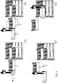
- Fig. 1 The drawing shows in four views a large number of container types that are delivered in the distribution center to a respective pallet of articles and have to be depalletized.
- the representation 1.1 of the Fig. 1 shows a standardized pallet 1 with reusable containers 2 arranged on it, which have a respective handle recess 5 both on the respective longitudinal side wall 3 and on the respective transverse side wall 4, since the containers are filled by the producer of the fruit and vegetable products and arranged in a stack on the pallets 1 and this takes place manually.
- the illustration 1.1 shows containers with a base area of 600 by 400 mm, for example, which can be at different heights, depending on which products are received in the containers
- the illustration 1.2 shows a pallet 1 with containers 2 with a base area of 300 times each 400 mm, and at a height of the respective container 2 that differs from the container 2 according to illustration 1.1.
- the representation 1.3 of the Fig. 1 again shows a pallet 1 with disposable containers 6 with stacking lugs 7 on the respective transverse side of the container 6 and a base area of 600 by 400 mm.
- the representation 1.4 of the Fig. 1 shows a pallet 1 with disposable containers 1 with a respective base area of 300 by 400 mm and less Height than the disposable containers 6 according to illustration 1.3 and stacking lugs 7 in the respective corner area of the container 6.
- FIG. 6 shows a reusable container in the form of a folding box 8, so that it can be seen that different types of containers with fruit and vegetable products are delivered to the distribution center and that there is considerable need for a device that is designed for the automated handling of the depalletizing of all types of container shown.
- FIG. 2 The drawing shows an embodiment of the device 9 according to the invention, which is integrated into a gantry robot system 10 and can therefore be moved both in the vertical axis direction Y and in the transverse direction Z in a storage rack (not shown in detail) and in a manner orthogonal thereto in order to have access to the pallets temporarily stored there with the with reference to the Fig. 1 explained different container types.
- FIG. 3 the drawing shows a schematic perspective representation of the device 9 with the already in Fig. 2 explained coordinate system.
- the device 1 has a holding device 11 on which a suction device 12 is provided in the form of suction means 13 arranged at a distance from one another, which can be brought up to a side wall of a disposable container 6, can be brought into contact there and via the generation of negative pressure can exert a suction force on the side wall of the disposable container 6 by means of a suction pump (not shown in detail), which is sufficient for the disposable container to be raised in a predetermined manner while maintaining the suction force to create a space between the raised disposable container and the disposable container or a pad arranged below it can, so that the support plate or undercarriage plate 14 can be moved into the space.
- a suction pump not shown in detail
- the device 1 also has a receptacle 15 on which two supports 16 extending away from the support plate 14 at an angle to it are arranged, on which a transverse support 17 is arranged displaceably in the vertical axis direction Y.
- An engagement device 18 which is designed to bring about a releasable engagement position with a handle recess of a container, is also arranged on the receptacle 15, as will be explained below.
- the device 9 also has a holding means 19 which is designed and provided for detachable arrangement or support on an upper edge region of a respective container, as will be explained in more detail below.
- Fig. 4 shows the device 9 in several representations when depalletizing disposable containers 6 with respective stacking lugs 7 in the corner area of the disposable containers 6.
- the device 9 is brought up to a side wall 20 of the disposable container 6 in such a way that the suction means 13 come to rest against the side wall 20.
- a pump not shown in detail
- negative pressure can be generated between the suction means 13 and the side wall 20, so that the side wall 20 and thus the disposable container 6 can be acted upon with a holding force which is sufficiently large without the development of a pressure force on the side wall 20 a lifting of the holding device 11 with the suction device 12 formed thereon with the suction means 13, an intermediate space 21 can be formed between the disposable container 6 to be depalletized and the further disposable container 6 arranged below it.
- the front stacking lugs 7 facing the device come out of engagement and the undercarriage plate or support plate 14 can be shifted into the space 21 until the disposable container 6 to be depalletized rests on the underride plate or carrier plate 14, as is the case in illustration 4.4 of the Fig. 4 can be seen.
- the plate 14 is pushed so far under the underside or lower surface 22 of the disposable container 6 until the The focus of the disposable container 6 with the fruit or vegetable products contained therein comes to rest on the plate 14, and the rear stacking lugs 7 also disengage.
- the suction device 12 can move along with the angularly adjusting configuration of the side wall 20 due to the lifting of the one-way container 6, that is, it can change at an angle relative to the vertical axis direction of the carrier 16, so that despite the angle change of the side wall 20 relative to the vertical axis direction the carrier 16 continues to have a slight negative pressure to hold the side wall 20 is sufficient.
- the device 9 can be displaced in the Z direction in such a way that the disposable container 6 comes to rest over a conveyor belt 23 shown schematically in illustration 4.6 with reference numeral 23. Then the support plate 14 can be pulled away from under the disposable container 6 and that again in the Z-direction and the negative pressure applied to the suction device 12 is canceled, the depalletized disposable container 6 is, as shown in the illustration 4.7 of Fig.
- the device 9 is, as can be seen in illustration 4.8, ready for the next depalletizing process and can be moved with the suction device 12 in the direction of the side wall of a further container 6 adjacent to the container 6 that has just been depalletized and the process of depalletizing this next container 6 can be carried out.
- FIG. 5 The drawing shows in several representations the process of depalletizing reusable containers 2, each of which has transverse side walls 4 with handle recesses 5. As shown by the representations of the Fig. 5 As can be seen, the reusable containers 2 also have corresponding handle recesses 5 on the longitudinal side walls 3, so that the device 9 according to the invention also enables the reusable containers 2 to be depalletized from the longitudinal side walls 3.
- the device 9 is moved towards the transverse side wall 4 of the container 3 in the upper container position and the position of the handle recess 5 is detected via a sensor device and the engagement device 18 with the gripping finger 24 at such a height Y-direction positioned so that the gripping finger 24 can be moved into the handle recess 5 via a translational movement in the Z-direction until the gripping finger 24 penetrates the handle recess 5, as shown in Figure 5.2 of Fig. 5 can be seen.
- the rubber lip 27 can apply a holding force to the edge 25 from above, with any existing deformations of the edge region of the edge 25 being able to be compensated for by the elasticity of the rubber lip 27.
- FIG. 7 The drawing can also be seen, for this purpose, the holding means 19 provided with the rubber lip 27 in the form of a pivot holder 28 is lowered via an actuator 29 in the form of a pneumatic cylinder 30 in a pivoting movement on the pivot axis 31 onto the edge 25 of the reusable container 2, like this can be seen from the double arrow 32.
- the holding means 19 of in Fig. 7 The device 9 shown has a receiving plate 34 in the form of a bracket 33, on which the rubber lip 27 is arranged at the front edge area and a schematically illustrated spring device 35 is provided on a lower side 35 of the bracket 33, which acts as a stop damper and is located in the Gripping finger 24 located in the handle recess 5 can gently come to rest from above, so that the edge 25 is clamped between the container, which can be moved in the Y direction to lift the container 2, as can be seen from the double arrow 36, and the rubber lip 27 can without a compressive force being exerted on the transverse side wall 4, and thus no damage to the fruit and vegetable products in the container 2 can take place.
- the illustration 5.3 shows that by lifting the container 2 relative to the container 2 arranged underneath, an intermediate space 21 is formed into which the support plate or underrun plate 14 can be moved until it is in the position shown in illustration 5.4 relative to the underside 22 of the container and the container is completely lifted from the other container below.
- the bundle located on the support plate 14 can be separated from the bundle stack by a displacement movement of the device 9 carrying the bundle, as shown in Figure 5.5 of FIG Fig. 5 can be seen and then the support plate 14 can be pulled away from the bottom 22 of the container 2 by a corresponding displacement movement according to the illustration 5.6 to the left, so that the container 2 comes to rest on the conveyor belt 23 and is conveyed by this for further handling, as shown on the basis the representation 5.7 of the Fig. 5 can be seen in the drawing.
- FIG. 6 The drawing shows a schematically illustrated folding box 8 with fruit and vegetable products located therein and a device 9 according to the present invention located in the clamping position with the upper edge 25 and the handle recess 5. Since the transverse side walls 4 of the folding box 8 are designed to be foldable, it is essential that these transverse side walls 4 are not subjected to a compressive force, as is the case with the known one explained at the beginning Device is the case, so that the type of container folding box can not be handled by the known device. In contrast to this, the device according to the invention can also be used to depalletize the folding box usually used for transporting fruit and vegetable products with the device according to the invention and according to the method according to the invention.
- the invention is characterized in that with the device according to the invention and according to the method according to the invention, all known container types can be automatically depalletized which are used for the transport of fruit and vegetable products in distribution centers and for further transport for sale to the buyer of the fruit and vegetable products .
- the device according to the invention and the method according to the invention provide a significant relief in the depalletizing of the container and for a quick transfer and very short dwell times in the distribution centers.
- the device according to the invention does not act on the side walls of the container with a clamping force or side force directed towards the interior of the container, the risk of damage to the sensitive fruit and vegetable products when depalletizing is eliminated. Likewise, the risk of the side walls of the container being torn open or impressed is eliminated.
- the respective position of the handle recesses of the container can be precisely detected via a sensor device and the gripping finger can thus be positioned exactly in the handle recess.
- the container By lifting the gripping finger with the holding means resting on the upper edge of the container, the container can be clamped without the application of side force to the container walls and is supported from the underside via the undercarriage plate.
- non-returnable containers are supported from the underside of the base plate so that centering tabs or centering corners on the containers are not damaged.
- Such disposable containers are raised by the suction force applied by the suction device, in that the suction device can be lifted on one side together with the container until the support plate or undercarriage plate is inserted into the space and the container rests on the carrier plate or undercarriage plate.
- the container By releasing the suction force and moving out the support plate or undercarriage plate, the container can then be set down on the removal belt and any short blowing impulse can remove any contamination from the suction device.
- the containers depalletized in this way be they one-way or reusable containers or also folding boxes with the fruit and vegetable products contained therein, are moved to a removal belt and placed on it in order to be able to be transported for further distribution in the distribution center.
- the respective containers only have to be lifted by about 25 mm in the Y direction and the resulting gap is sufficient to insert the undercarriage plate or support plate into the gap to support the container to be depalletized from below.
- the base plate is moved beyond the center of gravity of the container in the Z-direction and in this way the container is supported from below on the one hand and an unintentional detachment of the container from the base plate during transport to the removal belt is eliminated on the other.
- piece goods containers were mentioned above which are filled with perishable goods, such as in particular fruit and vegetable products, this is not to be interpreted as a restriction, since empty piece goods containers can also be depalletized with the device and the method according to the invention, as well as piece goods containers that are filled with other goods, such as drugstore items or personal care products or goods of any other kind.
Landscapes
- Engineering & Computer Science (AREA)
- Mechanical Engineering (AREA)
- Transportation (AREA)
- Structural Engineering (AREA)
- Civil Engineering (AREA)
- Life Sciences & Earth Sciences (AREA)
- Geology (AREA)
- Robotics (AREA)
- De-Stacking Of Articles (AREA)
- Manipulator (AREA)
- Warehouses Or Storage Devices (AREA)
- Stacking Of Articles And Auxiliary Devices (AREA)
- Container Filling Or Packaging Operations (AREA)
- Hooks, Suction Cups, And Attachment By Adhesive Means (AREA)
- Specific Conveyance Elements (AREA)
- Load-Engaging Elements For Cranes (AREA)
Priority Applications (3)
| Application Number | Priority Date | Filing Date | Title |
|---|---|---|---|
| SI201931044T SI3730432T1 (sl) | 2019-04-25 | 2019-11-08 | Naprava in postopek za depaletiranje drug vrh drugega zložljivih vsebnikov za kosovno blago |
| HRP20260499TT HRP20260499T1 (hr) | 2019-04-25 | 2019-11-08 | Uređaj i postupak skidanja složivih spremnika komadne robe s paleta |
| RS20260393A RS67934B1 (sr) | 2019-04-25 | 2019-11-08 | Uređaj i metod za uklanjanje komada koji se mogu složiti sa paleta |
Applications Claiming Priority (1)
| Application Number | Priority Date | Filing Date | Title |
|---|---|---|---|
| DE102019110704.0A DE102019110704B3 (de) | 2019-04-25 | 2019-04-25 | Vorrichtung und Verfahren zum Depalettieren von stapelbaren Stückgutgebinden |
Publications (3)
| Publication Number | Publication Date |
|---|---|
| EP3730432A2 true EP3730432A2 (fr) | 2020-10-28 |
| EP3730432A3 EP3730432A3 (fr) | 2020-11-04 |
| EP3730432B1 EP3730432B1 (fr) | 2026-02-11 |
Family
ID=68501419
Family Applications (4)
| Application Number | Title | Priority Date | Filing Date |
|---|---|---|---|
| EP21156034.7A Active EP3858768B1 (fr) | 2019-04-25 | 2019-11-08 | Procédé de dépallétisation des récipients pour marchandise de détail empilables |
| EP19207984.6A Active EP3730433B1 (fr) | 2019-04-25 | 2019-11-08 | Dispositif de dépalettisation doté d'un dispositif de dépalettisation de récipients empilables pour marchandise de détail et procédé de dépalettisation de récipients empilables pour marchandise de détail |
| EP19207977.0A Active EP3730432B1 (fr) | 2019-04-25 | 2019-11-08 | Dispositif et procédé de dépalettisation de récipients empilables pour marchandise de détail |
| EP19208345.9A Active EP3730434B1 (fr) | 2019-04-25 | 2019-11-11 | Procédé et système de préparation de commandes de marchandises déjà placées dans des récipients empilables sur des palettes dans un entrepôt sur une palette cible |
Family Applications Before (2)
| Application Number | Title | Priority Date | Filing Date |
|---|---|---|---|
| EP21156034.7A Active EP3858768B1 (fr) | 2019-04-25 | 2019-11-08 | Procédé de dépallétisation des récipients pour marchandise de détail empilables |
| EP19207984.6A Active EP3730433B1 (fr) | 2019-04-25 | 2019-11-08 | Dispositif de dépalettisation doté d'un dispositif de dépalettisation de récipients empilables pour marchandise de détail et procédé de dépalettisation de récipients empilables pour marchandise de détail |
Family Applications After (1)
| Application Number | Title | Priority Date | Filing Date |
|---|---|---|---|
| EP19208345.9A Active EP3730434B1 (fr) | 2019-04-25 | 2019-11-11 | Procédé et système de préparation de commandes de marchandises déjà placées dans des récipients empilables sur des palettes dans un entrepôt sur une palette cible |
Country Status (12)
| Country | Link |
|---|---|
| EP (4) | EP3858768B1 (fr) |
| AT (3) | AT522556B1 (fr) |
| CH (4) | CH716125B1 (fr) |
| DE (1) | DE102019110704B3 (fr) |
| DK (4) | DK3730432T3 (fr) |
| ES (4) | ES3066555T3 (fr) |
| FI (3) | FI3858768T3 (fr) |
| HR (4) | HRP20260499T1 (fr) |
| LT (4) | LT3858768T (fr) |
| PL (4) | PL3858768T3 (fr) |
| RS (4) | RS67747B1 (fr) |
| SI (4) | SI3730433T1 (fr) |
Cited By (1)
| Publication number | Priority date | Publication date | Assignee | Title |
|---|---|---|---|---|
| CN113788316A (zh) * | 2021-09-13 | 2021-12-14 | 南京紫峰家具有限公司 | 一种智能药房自动取药设备及取药方法 |
Families Citing this family (24)
| Publication number | Priority date | Publication date | Assignee | Title |
|---|---|---|---|---|
| CN113879854B (zh) * | 2020-07-01 | 2023-05-30 | 广东格兰仕集团有限公司 | 一种薄板单层筛选装置 |
| CN112093645B (zh) * | 2020-10-13 | 2022-06-10 | 中源家居股份有限公司 | 一种家居产品用智能仓储系统堆垛方法及设备 |
| CN112623589A (zh) * | 2020-12-16 | 2021-04-09 | 吴兰 | 一种用于农产品产地初加工的可多层码垛的蔬菜保鲜贮藏装置 |
| EP4277864A1 (fr) * | 2021-01-12 | 2023-11-22 | Premium Robotics GmbH | Système de préparation de commandes comprenant des contenants |
| DE202021102751U1 (de) * | 2021-05-19 | 2022-08-25 | Autefa Solutions Germany GmbH | Stapeleinrichtung |
| US12678942B2 (en) | 2021-06-08 | 2026-07-14 | Symbotic Canada, Ulc | Tool for palletizing mixed load products, palletizing robot including the tool, and method therefor |
| DE102021115950A1 (de) | 2021-06-21 | 2022-12-22 | Bayerische Motoren Werke Aktiengesellschaft | Depalettiervorrichtung zum Depalettieren von aufeinander gestapelten Ladungsträgern sowie Verfahren zum Depalettieren der Ladungsträger |
| CN113428659B (zh) * | 2021-07-28 | 2025-02-21 | 济南翼菲智能科技股份有限公司 | 一种立体式拆装盘机构 |
| EP4137281A1 (fr) * | 2021-08-19 | 2023-02-22 | Swisslog AG | Palettisation et/ou dépalletisation |
| DE102021124545B4 (de) * | 2021-09-22 | 2025-08-07 | Stöcklin Logistik Ag | Vorrichtung und Verfahren zur Sequenzierung von Ladeeinheiten in einer vorbestimmten Reihenfolge |
| WO2023095049A1 (fr) * | 2021-11-29 | 2023-06-01 | Ferag Ag | Dispositif de gestion du chargement d'unités de transport d'un système d'acheminement |
| CN114132761A (zh) * | 2021-12-08 | 2022-03-04 | 珠海格力智能装备有限公司 | 座板回收码垛装置 |
| CN114370148B (zh) * | 2021-12-17 | 2023-07-25 | 广东佳大建设工程有限公司 | 一种建筑用立式贴墙砖设备 |
| CN114314437B (zh) * | 2021-12-30 | 2023-11-03 | 佛山市海天(高明)调味食品有限公司 | 去托盘装置及送料系统 |
| CN114313951B (zh) * | 2021-12-31 | 2024-09-10 | 浙江杭可科技股份有限公司 | 一种简易无需顶升的存取货装置及托盘输送机构 |
| AT526215B1 (de) * | 2022-06-08 | 2025-06-15 | Tgw Logistics Group Gmbh | Transfervorrichtung und Verfahren zum Handhaben von Packeinheiten |
| CN115332916B (zh) * | 2022-07-04 | 2026-06-19 | 江苏博之旺自动化设备有限公司 | 新能源汽车高压线束组件自动送料装置 |
| IT202200021105A1 (it) * | 2022-10-13 | 2024-04-13 | Picklap S R L | Sistema e veicolo di commissionamento per prelevare articoli da supporti di stoccaggio di tipo pallet ed organizzarli su un supporto di commissionamento di tipo pallet |
| DE102023104580A1 (de) * | 2023-02-24 | 2024-08-29 | Noyes Robotics GmbH | Wechselvorrichtung für ein modulares Lagersystem zum Wechseln von Austauschkörpern bei Behältern, Wechselstation mit einer Wechselvorrichtung und einer Vertikaltransportvorrichtung, modulares Lagersystem mit einer Wechselstation und Verfahren zum Wechseln von Austauschkörpern |
| AT527108A1 (de) * | 2023-03-20 | 2024-10-15 | Tgw Logistics Group Gmbh | Vorrichtung und Verfahren zur automatisierten Beladung eines Ladungsträgers mit einen Ladestapel bildenden Ladeeinheiten |
| CN116477327B (zh) * | 2023-04-30 | 2025-09-16 | 杭州名度智能制造有限公司 | 一种袋装货物转运系统 |
| GB202314987D0 (en) * | 2023-09-29 | 2023-11-15 | Ocado Innovation Ltd | De-palletiser and palletiser |
| CN118446382B (zh) * | 2024-07-05 | 2024-11-19 | 杭州灵西机器人智能科技有限公司 | 针对混码单层垛型的松弛优化方法、电子设备和存储介质 |
| CN118992832B (zh) * | 2024-10-23 | 2025-03-07 | 纽科伦(新乡)起重机有限公司 | 一种压力储罐巡检及堆垛两用起重机 |
Citations (2)
| Publication number | Priority date | Publication date | Assignee | Title |
|---|---|---|---|---|
| DE19959285B4 (de) | 1999-12-09 | 2008-01-31 | J. Schmalz Gmbh | Vakuum-Greifsystem zum Greifen eines Objekts und Handhabungsgerät zum Handhaben eines Objekts mit Hilfe eines Vakuum-Greifsystems |
| EP2874925B1 (fr) | 2013-04-04 | 2015-10-14 | Atlantic C Handels- und Beratungs GmbH | Tête de grappin pour transporter des recipients pour marchandise de détail |
Family Cites Families (29)
| Publication number | Priority date | Publication date | Assignee | Title |
|---|---|---|---|---|
| US3523601A (en) * | 1967-03-02 | 1970-08-11 | Alvey Inc | Carton palletizing apparatus |
| DE1907109A1 (de) * | 1969-02-13 | 1970-09-03 | Von Opel Dipl Ing Fritz | Verfahren und Vorrichtung zum Aufnehmen von beispielsweise auf Paletten gestapelten Flaschenkaesten |
| DE2724978C2 (de) | 1977-06-02 | 1985-04-04 | Schaefer Förderanlagen- und Maschinenbau GmbH, 8043 Unterföhring | Vorrichtung zum Aufeinandersetzen von Kästen |
| DE7935243U1 (de) | 1979-12-14 | 1981-08-27 | Holstein Und Kappert Gmbh, 4600 Dortmund | Vorrichtung zum umsetzen von mit ausnmehmungen ausgestatteten stueckguetern |
| JPS6120286U (ja) * | 1984-07-13 | 1986-02-05 | 不二輸送機工業株式会社 | 筐体積層用ロボツトハンド |
| GB8726152D0 (en) * | 1987-11-07 | 1987-12-09 | Ledsham Eng Co Ltd | Stacking equipment |
| DE3835032A1 (de) * | 1988-10-14 | 1990-04-19 | Niepmann Traylift Transport | Verfahren und vorrichtung zum entstapeln von blockweise auf paletten gestapelten zuschnitten |
| DE3915139A1 (de) * | 1989-05-09 | 1990-11-15 | Focke & Co | Verfahren und anlage zum umordnen von sortenweise palettierten gegenstaenden zu gruppen bestimmter sortenzusammenstellung |
| DE4426615C1 (de) | 1994-07-27 | 1995-09-14 | Ludwig Stiny | Vorrichtung zum Stapeln oder Entstapeln von stapelbarem Gut |
| DE4427488A1 (de) * | 1994-08-03 | 1996-02-08 | Beumer Maschf Bernhard | Verfahren zum Palettieren von Stückgutteilen und Stückgutgreifer insbesondere für Roboter, insbesondere zur Paketpalettierung |
| DE19653953A1 (de) * | 1996-12-21 | 1998-06-25 | Topack Verpacktech Gmbh | Verfahren und Vorrichtung zum Entpalettieren von Artikeln |
| DE10123081C1 (de) * | 2001-05-11 | 2002-11-07 | Krones Ag | Drehvorrichtung |
| US20070280812A1 (en) * | 2006-05-17 | 2007-12-06 | Axium Inc. | Tool and method for mixed palletizing/depalletizing |
| AT507166B1 (de) | 2008-08-12 | 2010-11-15 | Moosburger Logistics Network & | Fördertechnikunterstützte kommissionierung von waren |
| DE102008039110A1 (de) * | 2008-08-21 | 2010-02-25 | Krones Ag | Greifervorrichtung zum gleichzeitigen Erfassen mehrerer Gebinde und/oder Kästen mit Getränkebehältern und Verfahren zur Justierung der Greifervorrichtung |
| DE102009056639A1 (de) * | 2009-12-02 | 2011-06-09 | Kuka Roboter Gmbh | Verfahren und Vorrichtung zur automatisierten Kommissionierung von Gebinden |
| DE102010018963A1 (de) * | 2010-04-28 | 2011-11-03 | IPR-Intelligente Peripherien für Roboter GmbH | Robotergreifer und Handhabungsroboter |
| EP2441709B1 (fr) | 2010-10-15 | 2014-01-29 | Prospect AB | Préhenseur pour ramasser des marchandises pallétisées |
| DE202010012945U1 (de) * | 2010-11-19 | 2012-02-22 | Hubtex Maschinenbau Gmbh & Co. Kg | Glasplattentransportfahrzeug |
| JP5717007B2 (ja) * | 2012-11-19 | 2015-05-13 | 株式会社安川電機 | ロボットシステム、ロボットハンド、ロボット |
| JP5860083B2 (ja) * | 2014-03-04 | 2016-02-16 | ファナック株式会社 | ロボットハンドを用いたコンテナ搬送装置 |
| JP6597061B2 (ja) * | 2014-09-02 | 2019-10-30 | 株式会社ダイフク | 物品搬送設備 |
| JP6559413B2 (ja) * | 2014-11-13 | 2019-08-14 | 株式会社東芝 | 移載装置及び荷物取出方法 |
| CN205363927U (zh) * | 2015-12-25 | 2016-07-06 | 广东水利电力职业技术学院 | 周转箱用的侧提底托式搬运机械手 |
| DE102016109310A1 (de) * | 2016-05-20 | 2017-11-23 | Deutsche Post Ag | Rutsche und Sortiereinrichtung sowie Verfahren zum Sortieren von Stückgut |
| DE102017112305A1 (de) * | 2017-01-20 | 2018-07-26 | Witron Vermögensverwaltungs Gmbh | Verfahren und vorrichtung zur kommissionierung von waren mit begrenzter haltbarkeit |
| JP2018122945A (ja) * | 2017-01-30 | 2018-08-09 | 株式会社東芝 | 可変型物品保持装置、移載装置、ロボットハンドリングシステム、および移載装置の制御方法 |
| EP3441327A1 (fr) * | 2017-08-09 | 2019-02-13 | Air Vol, S.A. | Grue empileuse roulante |
| CH714115A1 (de) * | 2017-09-04 | 2019-03-15 | Ferag Ag | Förderanlage mit Funksystem. |
-
2019
- 2019-04-25 DE DE102019110704.0A patent/DE102019110704B3/de active Active
- 2019-04-29 CH CH00570/19A patent/CH716125B1/de not_active IP Right Cessation
- 2019-05-13 AT ATA170/2019A patent/AT522556B1/de active
- 2019-11-07 AT ATA360/2019A patent/AT522558B1/de active
- 2019-11-07 CH CH01409/19A patent/CH716129B1/de unknown
- 2019-11-07 CH CH00130/21A patent/CH717051B1/de unknown
- 2019-11-08 FI FIEP21156034.7T patent/FI3858768T3/fi active
- 2019-11-08 PL PL21156034.7T patent/PL3858768T3/pl unknown
- 2019-11-08 LT LTEP21156034.7T patent/LT3858768T/lt unknown
- 2019-11-08 LT LTEP19207977.0T patent/LT3730432T/lt unknown
- 2019-11-08 DK DK19207977.0T patent/DK3730432T3/da active
- 2019-11-08 SI SI201930940T patent/SI3730433T1/sl unknown
- 2019-11-08 DK DK21156034.7T patent/DK3858768T3/da active
- 2019-11-08 PL PL19207984.6T patent/PL3730433T3/pl unknown
- 2019-11-08 RS RS20260169A patent/RS67747B1/sr unknown
- 2019-11-08 HR HRP20260499TT patent/HRP20260499T1/hr unknown
- 2019-11-08 ES ES19207977T patent/ES3066555T3/es active Active
- 2019-11-08 DK DK19207984.6T patent/DK3730433T3/da active
- 2019-11-08 RS RS20260393A patent/RS67934B1/sr unknown
- 2019-11-08 ES ES21156034T patent/ES3060363T3/es active Active
- 2019-11-08 LT LTEP19207984.6T patent/LT3730433T/lt unknown
- 2019-11-08 EP EP21156034.7A patent/EP3858768B1/fr active Active
- 2019-11-08 RS RS20250545A patent/RS66862B1/sr unknown
- 2019-11-08 FI FIEP19207984.6T patent/FI3730433T3/fi active
- 2019-11-08 SI SI201931021T patent/SI3858768T1/sl unknown
- 2019-11-08 SI SI201931044T patent/SI3730432T1/sl unknown
- 2019-11-08 HR HRP20250778TT patent/HRP20250778T1/hr unknown
- 2019-11-08 EP EP19207984.6A patent/EP3730433B1/fr active Active
- 2019-11-08 PL PL19207977.0T patent/PL3730432T3/pl unknown
- 2019-11-08 FI FIEP19207977.0T patent/FI3730432T3/fi active
- 2019-11-08 EP EP19207977.0A patent/EP3730432B1/fr active Active
- 2019-11-08 ES ES19207984T patent/ES3034781T3/es active Active
- 2019-11-08 HR HRP20260188TT patent/HRP20260188T1/hr unknown
- 2019-11-11 DK DK19208345.9T patent/DK3730434T3/da active
- 2019-11-11 PL PL19208345.9T patent/PL3730434T3/pl unknown
- 2019-11-11 ES ES19208345T patent/ES2920125T3/es active Active
- 2019-11-11 SI SI201930296T patent/SI3730434T1/sl unknown
- 2019-11-11 RS RS20220581A patent/RS63326B1/sr unknown
- 2019-11-11 EP EP19208345.9A patent/EP3730434B1/fr active Active
- 2019-11-11 HR HRP20220923TT patent/HRP20220923T1/hr unknown
- 2019-11-11 LT LTEP19208345.9T patent/LT3730434T/lt unknown
- 2019-11-25 AT ATA379/2019A patent/AT522557B1/de active
- 2019-12-04 CH CH01547/19A patent/CH716130B1/de unknown
Patent Citations (2)
| Publication number | Priority date | Publication date | Assignee | Title |
|---|---|---|---|---|
| DE19959285B4 (de) | 1999-12-09 | 2008-01-31 | J. Schmalz Gmbh | Vakuum-Greifsystem zum Greifen eines Objekts und Handhabungsgerät zum Handhaben eines Objekts mit Hilfe eines Vakuum-Greifsystems |
| EP2874925B1 (fr) | 2013-04-04 | 2015-10-14 | Atlantic C Handels- und Beratungs GmbH | Tête de grappin pour transporter des recipients pour marchandise de détail |
Cited By (1)
| Publication number | Priority date | Publication date | Assignee | Title |
|---|---|---|---|---|
| CN113788316A (zh) * | 2021-09-13 | 2021-12-14 | 南京紫峰家具有限公司 | 一种智能药房自动取药设备及取药方法 |
Also Published As
Similar Documents
| Publication | Publication Date | Title |
|---|---|---|
| EP3730432B1 (fr) | Dispositif et procédé de dépalettisation de récipients empilables pour marchandise de détail | |
| DE102007046919B4 (de) | Greifer zum automatischen Ergreifen von Packeinheiten | |
| EP0482406A1 (fr) | Dispositif de maniement pour articles tels que cartons | |
| DE102013008872A1 (de) | Vorrichtung und Verfahren zum Entpacken und Zuführen von Artikeln | |
| DE102011108798A1 (de) | Vorrichtung und Verfahren zum Entpacken und Zuführen von flach gefalteten und aufrecht stehenden Packungsmänteln | |
| WO2020035160A1 (fr) | Procédé de transfert et d'insertion d'articles dans des suremballages et dispositif de mise en œuvre du procédé | |
| EP3666696A1 (fr) | Dispositif et procede pour manipuler des couches de marchandises unitaires superposees | |
| DE102006062528A1 (de) | Vorrichtung und Verfahren zur Umsetzung von Stückgut | |
| DE102019128197B4 (de) | Depalettieranordnung mit einer Vorrichtung zum Depalettieren von stapelbaren Stückgutgebinden und Verfahren zum Depalettieren von stapelbaren Stückgutgebinden | |
| DE4206038A1 (de) | Vorrichtung zum aufloesen und bilden von stueckgutstapeln | |
| DE102018203180A1 (de) | Verpackungsvorrichtung für Artikel und Verfahren zum Verpacken von Artikeln | |
| WO2023156341A1 (fr) | Procédé et dispositif d'empilement automatique de paquets sur un support en couches multiples | |
| DE102010034992B4 (de) | Einrichtung zur Handhabung quaderförmiger Gegenstände | |
| DE102007036900B4 (de) | Verfahren zum Abstapeln oder Stapeln von Gebinden sowie Vorrichtung zum Durchführen dieses Verfahrens | |
| DE202019005286U1 (de) | Vorrichtung zum Depalettieren von stapelbaren Stückgutgebinden | |
| DE3203757A1 (de) | Vorrichtung zum zwischenstapeln von gegenstaenden | |
| WO2023006856A1 (fr) | Plateau, pile de plateaux et procédé de chargement/déchargement de plateaux | |
| DE102017116176A1 (de) | Tasten-Bearbeitung und -Montage mittels Trays | |
| DE102020006488B3 (de) | Logistiksystem zum Zuführen von Lagerteilen von einem Lagerort zu einer Entnahmestelle | |
| DE102010049192B4 (de) | Greifersystem und Verfahren zum Ergreifen und Anheben von Objekten | |
| DE202016104018U1 (de) | Teileträger für die automatisierte Handhabung von Teilen | |
| DE102023130970A1 (de) | Greiferkopf und Verfahren zur Handhabung von Verpackungszuschnitten |
Legal Events
| Date | Code | Title | Description |
|---|---|---|---|
| PUAI | Public reference made under article 153(3) epc to a published international application that has entered the european phase |
Free format text: ORIGINAL CODE: 0009012 |
|
| STAA | Information on the status of an ep patent application or granted ep patent |
Free format text: STATUS: THE APPLICATION HAS BEEN PUBLISHED |
|
| PUAL | Search report despatched |
Free format text: ORIGINAL CODE: 0009013 |
|
| AK | Designated contracting states |
Kind code of ref document: A2 Designated state(s): AL AT BE BG CH CY CZ DE DK EE ES FI FR GB GR HR HU IE IS IT LI LT LU LV MC MK MT NL NO PL PT RO RS SE SI SK SM TR |
|
| AX | Request for extension of the european patent |
Extension state: BA ME |
|
| AK | Designated contracting states |
Kind code of ref document: A3 Designated state(s): AL AT BE BG CH CY CZ DE DK EE ES FI FR GB GR HR HU IE IS IT LI LT LU LV MC MK MT NL NO PL PT RO RS SE SI SK SM TR |
|
| AX | Request for extension of the european patent |
Extension state: BA ME |
|
| RIC1 | Information provided on ipc code assigned before grant |
Ipc: B65G 47/90 20060101AFI20200929BHEP Ipc: B65G 47/91 20060101ALI20200929BHEP Ipc: B65G 59/02 20060101ALI20200929BHEP Ipc: B65G 61/00 20060101ALI20200929BHEP |
|
| STAA | Information on the status of an ep patent application or granted ep patent |
Free format text: STATUS: REQUEST FOR EXAMINATION WAS MADE |
|
| 17P | Request for examination filed |
Effective date: 20201127 |
|
| RBV | Designated contracting states (corrected) |
Designated state(s): AL AT BE BG CH CY CZ DE DK EE ES FI FR GB GR HR HU IE IS IT LI LT LU LV MC MK MT NL NO PL PT RO RS SE SI SK SM TR |
|
| STAA | Information on the status of an ep patent application or granted ep patent |
Free format text: STATUS: EXAMINATION IS IN PROGRESS |
|
| P01 | Opt-out of the competence of the unified patent court (upc) registered |
Effective date: 20230516 |
|
| 17Q | First examination report despatched |
Effective date: 20230613 |
|
| GRAP | Despatch of communication of intention to grant a patent |
Free format text: ORIGINAL CODE: EPIDOSNIGR1 |
|
| STAA | Information on the status of an ep patent application or granted ep patent |
Free format text: STATUS: GRANT OF PATENT IS INTENDED |
|
| RIC1 | Information provided on ipc code assigned before grant |
Ipc: B65G 47/90 20060101AFI20250630BHEP Ipc: B65G 47/91 20060101ALI20250630BHEP Ipc: B65G 59/02 20060101ALI20250630BHEP Ipc: B65G 61/00 20060101ALI20250630BHEP Ipc: H01R 12/58 20110101ALI20250630BHEP Ipc: H01R 12/71 20110101ALI20250630BHEP Ipc: H01R 13/11 20060101ALI20250630BHEP |
|
| INTG | Intention to grant announced |
Effective date: 20250730 |
|
| GRAS | Grant fee paid |
Free format text: ORIGINAL CODE: EPIDOSNIGR3 |
|
| GRAA | (expected) grant |
Free format text: ORIGINAL CODE: 0009210 |
|
| STAA | Information on the status of an ep patent application or granted ep patent |
Free format text: STATUS: THE PATENT HAS BEEN GRANTED |
|
| AK | Designated contracting states |
Kind code of ref document: B1 Designated state(s): AL AT BE BG CH CY CZ DE DK EE ES FI FR GB GR HR HU IE IS IT LI LT LU LV MC MK MT NL NO PL PT RO RS SE SI SK SM TR |
|
| REG | Reference to a national code |
Ref country code: CH Ref legal event code: F10 Free format text: ST27 STATUS EVENT CODE: U-0-0-F10-F00 (AS PROVIDED BY THE NATIONAL OFFICE) Effective date: 20260211 Ref country code: GB Ref legal event code: FG4D Free format text: NOT ENGLISH |
|
| REG | Reference to a national code |
Ref country code: DE Ref legal event code: R096 Ref document number: 502019014362 Country of ref document: DE |
|
| REG | Reference to a national code |
Ref country code: IE Ref legal event code: FG4D Free format text: LANGUAGE OF EP DOCUMENT: GERMAN |
|
| REG | Reference to a national code |
Ref country code: FI Ref legal event code: FGE |
|
| REG | Reference to a national code |
Ref country code: CH Ref legal event code: R17 Free format text: ST27 STATUS EVENT CODE: U-0-0-R10-R17 (AS PROVIDED BY THE NATIONAL OFFICE) Effective date: 20260423 |
|
| REG | Reference to a national code |
Ref country code: NL Ref legal event code: FP |
|
| REG | Reference to a national code |
Ref country code: HR Ref legal event code: T1PR Ref document number: P20260499 Country of ref document: HR |
|
| REG | Reference to a national code |
Ref country code: DK Ref legal event code: T3 Effective date: 20260505 |
|
| REG | Reference to a national code |
Ref country code: ES Ref legal event code: FG2A Ref document number: 3066555 Country of ref document: ES Kind code of ref document: T3 Effective date: 20260513 |
|
| REG | Reference to a national code |
Ref country code: EE Ref legal event code: FG4A Ref document number: E025818 Country of ref document: EE Effective date: 20260508 |
|
| PG25 | Lapsed in a contracting state [announced via postgrant information from national office to epo] |
Ref country code: GR Free format text: LAPSE BECAUSE OF FAILURE TO SUBMIT A TRANSLATION OF THE DESCRIPTION OR TO PAY THE FEE WITHIN THE PRESCRIBED TIME-LIMIT Effective date: 20260512 |
|
| PG25 | Lapsed in a contracting state [announced via postgrant information from national office to epo] |
Ref country code: IS Free format text: LAPSE BECAUSE OF FAILURE TO SUBMIT A TRANSLATION OF THE DESCRIPTION OR TO PAY THE FEE WITHIN THE PRESCRIBED TIME-LIMIT Effective date: 20260611 Ref country code: PT Free format text: LAPSE BECAUSE OF FAILURE TO SUBMIT A TRANSLATION OF THE DESCRIPTION OR TO PAY THE FEE WITHIN THE PRESCRIBED TIME-LIMIT Effective date: 20260611 |
|
| PG25 | Lapsed in a contracting state [announced via postgrant information from national office to epo] |
Ref country code: BG Free format text: LAPSE BECAUSE OF FAILURE TO SUBMIT A TRANSLATION OF THE DESCRIPTION OR TO PAY THE FEE WITHIN THE PRESCRIBED TIME-LIMIT Effective date: 20260211 |