EP4006997B1 - Verfahren zur herstellung einer quantenvorrichtung - Google Patents
Verfahren zur herstellung einer quantenvorrichtung Download PDFInfo
- Publication number
- EP4006997B1 EP4006997B1 EP21209987.3A EP21209987A EP4006997B1 EP 4006997 B1 EP4006997 B1 EP 4006997B1 EP 21209987 A EP21209987 A EP 21209987A EP 4006997 B1 EP4006997 B1 EP 4006997B1
- Authority
- EP
- European Patent Office
- Prior art keywords
- gate
- substrate
- oxide
- front face
- sides
- Prior art date
- Legal status (The legal status is an assumption and is not a legal conclusion. Google has not performed a legal analysis and makes no representation as to the accuracy of the status listed.)
- Active
Links
Images




Classifications
-
- G—PHYSICS
- G06—COMPUTING OR CALCULATING; COUNTING
- G06N—COMPUTING ARRANGEMENTS BASED ON SPECIFIC COMPUTATIONAL MODELS
- G06N10/00—Quantum computing, i.e. information processing based on quantum-mechanical phenomena
-
- H—ELECTRICITY
- H10—SEMICONDUCTOR DEVICES; ELECTRIC SOLID-STATE DEVICES NOT OTHERWISE PROVIDED FOR
- H10N—ELECTRIC SOLID-STATE DEVICES NOT OTHERWISE PROVIDED FOR
- H10N60/00—Superconducting devices
- H10N60/10—Junction-based devices
- H10N60/128—Junction-based devices having three or more electrodes, e.g. transistor-like structures
-
- H—ELECTRICITY
- H10—SEMICONDUCTOR DEVICES; ELECTRIC SOLID-STATE DEVICES NOT OTHERWISE PROVIDED FOR
- H10D—INORGANIC ELECTRIC SEMICONDUCTOR DEVICES
- H10D48/00—Individual devices not covered by groups H10D1/00 - H10D44/00
- H10D48/383—Quantum effect devices, e.g. of devices using quantum reflection, diffraction or interference effects
- H10D48/3835—Semiconductor qubit devices comprising a plurality of quantum mechanically interacting semiconductor quantum dots, e.g. Loss-DiVincenzo spin qubits
-
- H—ELECTRICITY
- H10—SEMICONDUCTOR DEVICES; ELECTRIC SOLID-STATE DEVICES NOT OTHERWISE PROVIDED FOR
- H10N—ELECTRIC SOLID-STATE DEVICES NOT OTHERWISE PROVIDED FOR
- H10N60/00—Superconducting devices
- H10N60/01—Manufacture or treatment
-
- H—ELECTRICITY
- H10—SEMICONDUCTOR DEVICES; ELECTRIC SOLID-STATE DEVICES NOT OTHERWISE PROVIDED FOR
- H10N—ELECTRIC SOLID-STATE DEVICES NOT OTHERWISE PROVIDED FOR
- H10N60/00—Superconducting devices
- H10N60/01—Manufacture or treatment
- H10N60/0912—Manufacture or treatment of Josephson-effect devices
-
- G—PHYSICS
- G06—COMPUTING OR CALCULATING; COUNTING
- G06N—COMPUTING ARRANGEMENTS BASED ON SPECIFIC COMPUTATIONAL MODELS
- G06N10/00—Quantum computing, i.e. information processing based on quantum-mechanical phenomena
- G06N10/40—Physical realisations or architectures of quantum processors or components for manipulating qubits, e.g. qubit coupling or qubit control
Definitions
- the present invention relates to the field of quantum electronics. Its particularly advantageous application is the production of superconducting gates in quantum devices with quantum bits (called quantum bits or qubits), in particular for devices based on architectures with spin qubits or superconducting qubits.
- quantum devices with superconducting qubits make it possible to obtain good entanglement between qubits.
- these devices still have too much variability. They are particularly sensitive to small imperfections induced by manufacturing processes. In particular, they require a very high quality interface between the two superconducting reservoirs, to obtain a Josephson effect. It is also difficult to form a unit qubit via these devices.
- Spin qubit quantum devices can operate with fewer qubits and consume less energy. They can also benefit from manufacturing processes and microelectronics technologies to improve the reproducibility and increase the integration density of these spin qubit devices.
- This process makes it possible in particular to produce a quantum device with two qubits in series, in an active zone 11 of an SOI substrate 1, as illustrated in Fig. figure 2 .
- the two gates 22a make it possible to control these two qubits.
- the source and drain regions 31 form reservoirs of charge carriers for these two qubits.
- Such a quantum device with spin qubits nevertheless has an operating speed lower than that of a device with superconducting qubits.
- An object of the present invention is to overcome at least partly some of the disadvantages mentioned above.
- an object of the present invention is to propose a method for producing a quantum device reducing energy consumption while improving the operating speed.
- This lateral diffusion is carried out from the metal layer.
- This metallic layer comprises at least one metallic species capable of forming an alloy or a superconducting compound by reaction after diffusion within the grid. In this case the diffusion is called reactive diffusion. According to one possibility, the metallic species is superconducting before reaction and simply diffuses within the grid.
- a protective layer is advantageously formed at the front face of the substrate.
- the protective layer can thus prevent the diffusion of metallic species from a metallic layer on the surface of the substrate, for example deposited by a conformal deposition.
- the protective layer can also prevent diffusion or reaction on the surface of the substrate with metallic species originating from metallic residues formed following lateral diffusion from the sides of the grid.
- the method according to the invention thus makes it possible to produce a quantum device having a superconducting gate transistor architecture.
- the superconducting region formed by the method according to the invention also makes it possible to reduce the energy consumption of the device during operations on the qubits.
- the invention also relates to a quantum device having a superconducting gate transistor architecture as obtained by the method according to the invention.
- the transistor pattern provided further comprises a hard mask on the top of the gate, said hard mask being configured to prevent diffusion of at least one metal species into the gate from said top, so that the Formation of the superconducting region occurs only by lateral diffusion from the sides of the gate.
- a hard mask on the top of the gate, said hard mask being configured to prevent diffusion of at least one metal species into the gate from said top, so that the Formation of the superconducting region occurs only by lateral diffusion from the sides of the gate.
- the metal layer formed comprises at least one metal species among cobalt, platinum and vanadium.
- the metal layer is formed by conformal deposition of metal on the transistor pattern and on the protective layer on the front face of the substrate.
- the metal layer is formed by CVD deposition (acronym for Chemical Vapor Deposition) or by ALD deposition (acronym for Atomic Layer Deposition). This makes it possible to deposit at least one metallic species on the sides of the grid.
- the metal layer is formed by PVD deposition (acronym for Physical Vapor Deposition) with conditions allowing redeposition or resputtering (commonly called “sputtering” or “resputtering”) from the bottom of the patterns towards the sides of the grid , typically by plasma treatment.
- the metal layer is formed by poorly directional PVD deposition. This makes it possible to deposit at least one metallic species on the sides of the grid.
- the lateral diffusion is configured to propagate the at least one metal species from each of the flanks of the grid at least to the center of the grid, so that the superconducting region is formed over an entire width L g of the grid.
- the grid is thus completely superconducting. This improves the control of the quantum device thus formed.
- the gate has a width L g ⁇ 40 nm, preferably L g ⁇ 30 nm, preferably L g ⁇ 25 nm, preferably L g ⁇ 20 nm. This makes it possible to reduce the number of qubits entangled in the device.
- the grid has a width L g and the metal layer formed has a thickness e m ⁇ L g /5. This makes it possible to have a sufficient quantity of metal species in the metal layer, so that the entire gate can be made superconductive following lateral diffusion.
- the thickness e m may also depend on the metal used and/or the nature of the grid.
- the lateral diffusion is carried out by thermal annealing, for example by RCA type annealing (acronym for Rapid Thermal Annealing).
- the conditions of lateral diffusion or lateral silicidation may in particular depend on the metal used and the phase targeted.
- the table below gives examples of thickness ratios between different metals (Co, Pt and V) and silicon.
- the annealing environment can be under Ar, He or N 2 inert gas.
- the thickness of Si consumed is preferably less than or equal to half the gate width. This makes it possible to avoid forming a polyphase superconducting zone.
- the protective layer formed at the front face of the substrate has a thickness e' s greater than or equal to 2 nm during the formation of the superconducting region. This makes it possible to improve the sealing of the protective layer against the diffusion of metallic species.
- the differentiated oxidation is carried out from at least one plasma comprising oxygen-based species and hydrogen-based species.
- the hydrogen-based species are taken from dihydrogen H2, ammonia NH3, boron hydride HBr.
- the first plasma follows the second plasma.
- the first plasma is an H2 hydrogen plasma and the second plasma is an O2 oxygen plasma.
- the first and second plasmas are produced simultaneously from HBr/O2 plasma chemistry. This reduces the number of steps.
- HBr/O2 plasma chemistry can further be used to etch and form the transistor pattern. The steps of providing the transistor pattern and forming the protective layer can therefore be partly merged.
- the removal of the oxide formed at the sides of the grid is done by wet etching.
- the sides of the grid are exposed over at least 90% of their height h g , following removal of the deposited oxide.
- the oxide deposition is carried out by centrifugation.
- the substrate carries a plurality of transistor patterns.
- a subset of the plurality of transistor patterns is masked before the formation of the metal layer so as to avoid the formation of superconducting regions in the gates of the transistor patterns of said subset.
- a hard mask on a grid does not necessarily mean that the hard mask and the grid are directly in contact with each other, but it means that the hard mask at least partially covers the grid by being either directly in contact with it or by being separated from it by at least one other layer or at least one other element.
- a layer can also be composed of several sub-layers of the same material or of different materials.
- a substrate By a substrate, a layer, a device, “based” on a material M, is meant a substrate, a layer, a device comprising only this material M, or this material M and possibly other materials, for example alloying elements, impurities or doping elements.
- a spacer based on silicon nitride SiN can for example comprise non-stoichiometric silicon nitride (SiN), or stoichiometric silicon nitride (Si3N4), or even a silicon oxy-nitride (SiON).
- a spacer forms a ring around the grid, with a closed contour; the description of a spacer preferably means this unique spacer around the grid; however, the sectional illustrative drawings, generally in a plane parallel to the longitudinal direction of the channel, show two spacer parts on either side of the sides of the grid. By extension, these two spacer parts are often referred to as “the spacers”. This latter terminology may possibly be adopted in this application. Furthermore, the invention extends to embodiments in which at least two discontinuous spacers cover a grid pattern.
- the present invention notably allows the manufacture of at least one quantum device or a plurality of quantum devices on a substrate.
- This substrate can be massive or "bulk” according to the English terminology, or even of the semiconductor on insulator type, for example a silicon on insulator SOI substrate (acronym for "silicon on insulator”) or a germanium substrate on insulator GeOI (acronym for “germanium on insulator”).
- the invention can also be implemented more widely for different micro-electronic devices or components.
- microelectronic device any type of element produced with microelectronics means.
- These devices include in particular, in addition to devices for purely electronic purposes, micromechanical or electromechanical devices (MEMS, NEMS, etc.) as well as optical or optoelectronic devices (MOEMS, etc.).
- MEMS micromechanical or electromechanical devices
- MOEMS optical or optoelectronic devices
- successive stages of the manufacturing process are described below.
- the adjective “successive” does not necessarily imply, even if this is generally preferred, that the stages follow each other immediately, with intermediate stages possibly separating them.
- the term “step” means carrying out a part of the process, and can designate a set of sub-steps.
- the step of forming the protective layer can occur partly at the end of the step of providing the transistor pattern, so that these two steps are partly confused. This is for example the case when a plasma in HBr/O2 chemistry is used to etch and form the transistor pattern.
- This plasma can be extended, preferably by varying the conditions of said plasma, so as to form the protective layer.
- dielectric describes a material whose electrical conductivity is sufficiently low in the given application to serve as an insulator.
- a dielectric material preferably has a dielectric constant less than 7.
- the spacers are typically formed from a dielectric material.
- selective etching with respect to or “etching exhibiting selectivity with respect to” is meant an etching configured to remove a material A or a layer A with respect to a material B or d. a layer B, and having an etching speed of material A greater than the etching speed of material B. Selectivity is the ratio between the etching speed of material A to the etching speed of material B.
- thickness for a layer height for a device (grid for example) and depth for a cavity or an engraving.
- the thickness is taken in a direction normal to the main extension plane of the layer, the height and depth are taken in a direction normal to the base plane of the substrate.
- the main extension plane of the layer respectively the base plane of the substrate, is generally parallel to a lower face or an upper face of this layer, respectively of this substrate.
- a preferably orthonormal reference mark formed by the axes x, y, z is represented in the accompanying drawings.
- the substrate more precisely its lower face and/or its upper face, extends in the basal xy plane.
- the length is taken according to the direction carried by the x axis, called the longitudinal axis
- the width is taken according to the direction carried by the y axis.
- An element located “perpendicular” or “to the right of” another element means that these two elements are both located on the same line perpendicular to the basal plane, i.e. on the same line oriented along the z axis on the figures.
- a direction substantially normal to a plane means a direction having an angle of 90 ⁇ 10° relative to the plane.
- a first embodiment of the method is illustrated in figures 3 And 4A-4J .
- This first embodiment makes it possible to form a quantum device with at least two qubits, these qubits being electron spin qubits or superconducting qubits.
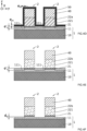
- Two transistor patterns 2 each comprising a gate dielectric 21, a gate 22a and a hard mask 40 stacked on a substrate 1 are provided 100 ( Figure 4A ).
- the substrate 1 is typically here an SOI substrate comprising an active region 11 on a buried oxide 10.
- the gate dielectric 21 is typically based on silicon dioxide SiO2, or based on a material with a high dielectric constant.
- the gate dielectric 21 typically has a thickness e g of between 1 nm and 5 nm.
- Gate 22a is typically based on polycrystalline silicon (polySi).
- the gate 22a typically has a width L g of less than 25 nm and a height h g of between 20 nm and 150 nm.
- the hard mask 40 is typically based on silicon nitride SiN or SiO2.
- the device is made on a solid silicon substrate.
- a dopant introduction step can be provided to ensure confinement of the electron, and/or dielectric materials, other than silicon oxide, can be provided. These dielectrics are based, for example, on nitride or alumina.
- the supply 100 of the two patterns of transistors 2 corresponds here to the formation of these patterns of transistors 2.
- the gates 22a are etched by conventional plasma etching, for example using a plasma in HBr/O2 chemistry.
- the formation 110 of a protective layer 111 ( figure 4B ) at the front face 101 of the substrate 1 can be done from an over-etching step directly successive to the etching of the gates 22a.
- This over-etching step aims to achieve differentiated oxidation 111a of the sides 221 and the front face 101.
- each grid 22a are oxidized over a thickness e f to form the oxide 222 ( figure 4B ).
- the front face is oxidized to a thickness e s to form oxide 111 ( figure 4B ).
- the differentiated oxidation 111a is configured so that the thickness e f of the oxide 222 is strictly less, for example at least 20% less and preferably at least 50% less, than the thickness e s of the oxide 111.
- the thickness e f of oxide 222 can be between 1 nm and 4 nm.
- the thickness e s of the oxide 111 can be between 3 nm and 10 nm.
- the HBr/O2 chemistry plasma used to etch the grids 22a is adapted to oxidize in a differentiated manner the sides 221 and the front face 101 at the end of etching the grids 22a.
- the HBr/O2 mixture is 40:1 (e.g. 200 sccm HBr to 5 sccm O2).
- the pressure is less than 6.7 Pa (50 mTorr), preferably less than 1.3 Pa (10 mTorr), for example 0.8 Pa (6 mTorr).
- the source power is greater than 200 W, preferably greater than 400 W (typically 500 W).
- the bias voltage is greater than 50 V, preferably greater than 60 V (typically 80 V).
- the temperature of the substrate is between 50°C and 70°C, preferably around 60°C.
- the overetching step is carried out sequentially by a first plasma based on hydrogen, for example based on dihydrogen H2 or ammonia NH3, followed by a second plasma based on oxygen O2.
- the first plasma here makes it possible to modify both the material of the active layer 11 over a depth d s from the front face 101, and the material of the grid 22a over a width d f from the sides 221.
- the portions modified by this first plasma are not engraved.
- This first plasma is configured so that the width d f is strictly less, for example at least 20% less and preferably at least 50% less, than the depth d s .
- the width d f can be between 1 nm and 4 nm.
- the depth d s can be between 3 nm and 10 nm.
- the second plasma makes it possible to preferentially oxidize the portions of active layer 11 and gate 22a modified by the first plasma.
- This makes it possible to form the oxide 111 of thickness e s and the oxide 222 of thickness e f .
- the oxide formed by oxidation of silicon can be larger than the silicon consumed during the oxidation.
- the oxide 111 can typically extend under the front face 101 and above the front face 101, so that the depth d s is not necessarily equal to the thickness e s .
- a thin oxide 222 is formed on the sides 221 of the gate 22a and a thick oxide 111 is formed on the front face 101 of the active layer 11.
- the next step consists of removing 111b the fine oxide 222 on the sides 221 of the grid 22a ( figure 4C ).
- This removal 111b can be done by wet etching, for example based on dilute hydrofluoric acid dHF (HF concentration of the order of 0.1% to 1%).
- this removal 111b is done by a SiCoNi TM type process, which typically comprises a delocalized plasma based on an NF3/NH3 mixture followed by sublimation annealing.
- the thickness e' s is greater than or equal to 2 nm.
- the sides 221 of the grid 22a are exposed again. Cleaning of the sides 221 can be carried out, for example by argon or helium plasma, before deposition of a metal layer 50.
- the metal layer 50 can be deposited in a conformal manner on the transistor patterns 2 and on the layer protection 111 ( figure 4D ).
- the metal layer 50 covers in particular the sides 221.
- This metal layer 50 comprises at least one superconducting element, for example taken from cobalt, platinum or vanadium. It has a thickness e m . This thickness e m is preferably chosen so that the entire gate 22a is transformed into a superconducting region at the end of the following lateral diffusion step.
- the width L above required to transform the gate 22a into a superconducting region is equal to L g /2.
- a thickness e m of metal layer 50 greater than or equal to the width L Si of polySi consumed during the transformation makes it possible to silicide the grid 22a over its entire width L g .
- the formation 120 of the superconducting region 22b within the gate 22a takes place by lateral diffusion of the metallic species from the flanks 221, that is to say mainly along y.
- This lateral diffusion is preferably configured so that the superconducting region 22b is formed over the entire width L g of the gate 22a ( Figure 4E ).
- two diffusion fronts develop from the two respective sides of the grid 22a. These diffusion fronts are substantially vertical and progress towards the median plane xz of the grid 22a.
- Gate 22a is completely transformed into superconducting region 22b when the fronts meet at this median plane xz.
- the presence of the hard mask 40 advantageously prevents diffusion of the metallic species from the top of the grid 22a. This prevents a third diffusion front from developing from the summit.
- the crystal quality of the superconducting region 22b formed by lateral joining of two diffusion fronts is better than the crystal quality of a superconducting region 22b formed by joining three fronts.
- the diffusion of the metallic species within the grid 22a is typically done by thermal annealing, for example at a temperature of 400 to 800°C. Diffusion conditions typically depend on the metal species chosen and its reactivity with silicon. Examples are provided in the table presented above.
- the protective layer 111 prevents the metallic species from diffusing into the active layer 11.
- the metallic residues are preferably cleaned, for example using a solution based on hydrogen peroxide H2O2 such as Caro (H 2 O 2 :H 2 SO4), aqua regia (HCI:HNO3) and/or SC1 (H 2 O:H 2 O 2 :NH 4 OH).
- the protective layer 111 can then be removed 140a so as to expose the active layer 11 ( figure 4F ).
- This removal 140a can be done by wet etching, for example based on HF hydrofluoric acid.
- the removal 140a of this protective layer 111 is done before the epitaxy step 300 of the source and drain regions. This removal can therefore be carried out directly after formation 130 of the superconducting region 22b, or subsequently, for example after formation 200 of the spacers. This last possibility can in particular improve the quality of interface between the active layer 11 and the future spacer 20.
- the spacer(s) 20 are formed 200 on either side of the grid patterns.
- the formation of spacers 20 based on SiN is a perfectly known standard step.
- the source and drain regions 31 are then formed 300 around the spacers 20 ( Figure 4H ) exteriors. These regions 31 are typically formed by epitaxy along z from the exposed zones of the active layer 11. This makes it possible to obtain raised source and drain regions 31 in a known manner, also called RSD (for Raised Source Drain).
- a standard silicidation 401 of the source and drain regions 31 can then be carried out to form silicidated portions 32 ( Figure 4I ).
- the hard mask 40 is kept at the top of the superconducting region 22b so as to avoid additional silicidation of the superconducting region 22b.
- the hard mask 40 can be removed 501 after siliciding the source and drain regions 31, so as to expose the top of the superconducting region 22b, as illustrated in Fig. figure 4J .
- a two-qubit quantum device comprising at least two superconducting regions 22b is thus advantageously formed.
- FIG. 5 And 6A-6J A second embodiment of the method is illustrated in figures 5 And 6A-6J .
- This second embodiment also makes it possible to form a quantum device with two qubits, these qubits being electron spin qubits or superconducting qubits.
- the formation 110 of the protective layer differs from the previous embodiment. Only the characteristics different from the first embodiment are described below, the other characteristics not described being deemed identical.
- Two transistor patterns 2 each comprising a gate dielectric 21, a gate 22a and a hard mask 40 stacked on a substrate 1 are provided here 100 ( Figure 6A ) independently of the formation step 110 of the protective layer.
- the formation 110 of the protective layer begins here after the etching of the gates 22a.
- This formation 110 is typically done in two stages: an oxide layer 60 is first formed between the transistor patterns 2, on the front face 101, as illustrated in Figure 6B .
- This oxide layer 60 for example a fluid oxide of the SoG type (acronym for Spin on Glass), can be deposited 112a by centrifugation.
- the deposition conditions by centrifugation can be chosen as a function of the density of transistor patterns 2 on the substrate, the height/width form factor of the spaces to be filled, and the desired thickness of oxide 60. in a known manner, the speed of the spinner will be adapted for a homogeneous deposition over the entire plate as well as the process time to control the thickness deposited. Annealing then makes it possible to solidify the oxide layer 60.
- a partial removal 112b of this oxide layer 60 is then carried out so as to form a protective layer 112 of thickness e s ( Figure 6C ).
- This recess 112b is preferably configured so that the thickness e s of the protective layer 112 is greater than 2 nm and/or greater than the thickness e g of the gate dielectric 21. This makes it possible to avoid any subsequent parasitic diffusion of metal in the active layer 11, particularly at the base of the transistor patterns, directly above the sides 221.
- This partial removal 112b can be carried out by wet etching based on HF or by plasma etching using fluorocarbon chemistry. A diluted HF solution of the order of 0.1% to 1% is preferably used. This makes it possible to obtain good etching selectivity with respect to the grid 22a and/or the hard mask 40.
- the removal 112b can also be done by a SiCoNi TM type process, which typically comprises a delocalized plasma based of an NF3/NH3 mixture followed by sublimation annealing.
- the sides 221 of the grid 22a are partly exposed at the end of this recess 112b, over at least 80% of their height h g , and preferably over at least 90% of their height h g .
- the metal layer 50 is then deposited 120 on the exposed sides 221 of the transistor patterns, as illustrated in Figure 6D .
- the lateral diffusion of the superconducting elements then takes place from the sides 221 covered by the metal layer 50, so as to form 130 the superconducting region 22b, as previously ( Figure 6E ).
- the metal residues are preferably cleaned, then the protective layer 112 is removed 140b so as to expose the front face 101 of the active layer 11 ( Figure 6F ).
- This second embodiment thus makes it possible to maintain a substantially constant thickness of active layer 11. This makes it possible to maintain a sufficient active layer thickness, typically greater than 3nm. Such a thickness of the active layer makes it possible to avoid phenomena of agglomeration or balling of the active layer during subsequent processes at high temperatures, for example during the epitaxy of raised RSD sources and drains.
- FIGS. 7A, 7B , 7C as well as figures 8A-8F And 9A-9D illustrate in a non-limiting manner some of these embodiments.
- the width of the spacers 20 can also be reduced, so as to bring the source and drain regions 31 closer to the channel (conventionally located under the superconducting region 22b).
- the standard silicide 32 of the source and drain regions 31 can be replaced by a superconducting silicide 33, for example of the same nature as the superconducting region 22b ( Figure 7C ).
- This can be interesting for certain applications, for example for transmon (superconducting charge qubit), gatemon (transmon with variable polarization) or even JoFET (FET with superconducting source and drain regions) applications.
- FIGS. 8A to 8F illustrate part of the process making it possible to co-integrate conventional FDSOI MOSFET transistors and superconducting gate quantum devices on the same substrate 1. This can be achieved by masking a portion of the transistor patterns 2 with a masking layer 70 before the formation 120 of the metal layer 50. This makes it possible to avoid the formation 130 of superconducting regions 22b in the gates 22a of the transistor patterns 2 masked.
- a step conventional photolithography makes it possible to mask part of the transistor patterns 2 by a resin 71 ( Figure 8B ).
- the masking layer 70 is then removed from the unmasked transistor patterns 2, for example by wet method from an HF solution or by isotropic plasma.
- the resin 71 is then removed, wetly or by O2 plasma, so as to obtain a first set 2a of transistor patterns 2 with masking layer 70, and a second set 2b of transistor patterns 2 without masking layer 70 ( Figure 8C ).
- the metal layer 50 can then be deposited conformally on the first and second sets 2a, 2b, as illustrated in figure 8D .
- the formation 130 of the superconducting regions 22b then takes place only within the gates 22a of the second set 2b of transistor patterns 2, as illustrated in Figure 8E .
- the masking layer 70 advantageously prevents the lateral diffusion of the superconducting elements within the gates 22a of the first set 2a of transistor patterns 2.
- the gates 22a of the first set 2a of transistor patterns 2 are thus preserved.
- the masking layer 70 can then be removed, as illustrated in Figure 8F .
- This removal can be done by wet etching using a solution of phosphoric acid H3PO4 if the masking layer 70 is based on SiN.
- Such an etching has in particular good selectivity with respect to the oxide 111, 112.
- an isotropic plasma etching can be carried out to remove the masking layer 70.
- a wet etching based on an HF solution can alternatively be carried out. be carried out if the masking layer 70 is based on SiO2.
- FIGS 9A to 9D illustrate part of the process making it possible to silicide the gates 22a of conventional MOSFET FDSOI transistors co-integrated with quantum devices with superconducting gates.
- the active layer 11 illustrated here is of constant thickness.
- the source and drain regions can here be formed directly in the active layer 11.
- This part of the method can also be implemented with raised source and drain regions, for example formed on an active layer 11 of non-constant thickness, such as described and illustrated previously.
- the hard mask 40 is removed from the top of the gates 22a of the set 2a, and kept on the top of the superconducting gates 22b of the set 2b ( Figure 9A ).
- a metallic layer 51 for example based on nickel or titanium, can then be deposited conformally on the patterns of the assemblies 2a, 2b ( Figure 9B ).
- a silicide can then be carried out, typically by thermal annealing, so as to partially or completely silicide the grids 22a, 23 of the assembly 2a ( Figure 9C ).
- This silicidation does not affect the superconducting gates 22b of the assembly 2b, which are protected by the spacers 20 and the hard masks 40.
- This silicidation can also make it possible to form silicidated portions 32 at the source and drain regions.
- quantum devices with a superconducting gate 22b and FDSOI MOSFET transistors with a non-superconducting silicide gate 23 are co-integrated on the same substrate 1 ( Figure 9D ).
Landscapes
- Engineering & Computer Science (AREA)
- Physics & Mathematics (AREA)
- Theoretical Computer Science (AREA)
- General Physics & Mathematics (AREA)
- Manufacturing & Machinery (AREA)
- Data Mining & Analysis (AREA)
- General Engineering & Computer Science (AREA)
- Condensed Matter Physics & Semiconductors (AREA)
- Mathematical Analysis (AREA)
- Mathematical Optimization (AREA)
- Pure & Applied Mathematics (AREA)
- Computing Systems (AREA)
- Evolutionary Computation (AREA)
- Mathematical Physics (AREA)
- Software Systems (AREA)
- Computational Mathematics (AREA)
- Artificial Intelligence (AREA)
- Superconductor Devices And Manufacturing Methods Thereof (AREA)
- Insulated Gate Type Field-Effect Transistor (AREA)
- Thin Film Transistor (AREA)
Claims (15)
- Verfahren zum Herstellen einer Quantenvorrichtung, das die folgenden Schritte umfasst:- Bereitstellen (100) eines Substrats (1), das eine Vorderseite (101) aufweist und mindestens ein Transistormuster (2) auf seiner Vorderseite (101) trägt,wobei das Transistormuster (2) in einem Stapel Folgendes umfasst:• ein Gate-Dielektrikum (21) auf der Vorderseite (101) des Substrats (1),• ein Gate (22a) auf dem Gate-Dielektrikum (21), wobei das Gate (22a) eine Oberseite und Seitenwände (221) aufweist,- Bilden (110) einer Schutzschicht (111, 112) auf Höhe der Vorderseite (101) des Substrats (1), wobei die Schutzschicht (111, 112) so konfiguriert ist, dass sie die Diffusion von mindestens einer Metallart in das Substrat (1) verhindert,- Bilden (120) einer Metallschicht (50) auf Basis mindestens einer Metallart zumindest auf den Seitenwänden (221) des Gates (22a),- Bilden (130) eines supraleitenden Bereichs (22b) im Gate (22a) durch seitliche Diffusion der mindestens einen Metallart aus den Seitenwänden (221) des Gates (22a).
- Verfahren nach dem vorhergehenden Anspruch, wobei das bereitgestellte Transistormuster (2) ferner eine Hartmaske (40) auf der Oberseite des Gates (22a) umfasst, wobei die Hartmaske (40) so konfiguriert ist, dass eine Diffusion mindestens einer Metallart im Gate (22a) von der Oberseite her verhindert, so dass das Bilden (130) des supraleitenden Bereichs (22b) nur durch seitliche Diffusion von den Seitenwänden (221) des Gates (22a) aus erfolgt.
- Verfahren nach einem der vorhergehenden Ansprüche, wobei die gebildete Metallschicht (50) mindestens eine Metallart ausgewählt aus Kobalt, Platin und Vanadium umfasst.
- Verfahren nach einem der vorhergehenden Ansprüche, wobei die Metallschicht (50) durch konforme Metallabscheidung auf dem Transistormuster (2) und auf der der Schutzschicht (111, 112) auf der Vorderseite (101) des Substrats (1) gebildet wird (120).
- Verfahren nach einem der vorhergehenden Ansprüche, wobei das Gate (22a) eine Breite Lg aufweist und die gebildete Metallschicht (50) eine Dicke von em ≥ Lg/5 aufweist.
- Verfahren nach einem der vorhergehenden Ansprüche, wobei die seitliche Diffusion durch thermisches Glühen erfolgt.
- Verfahren nach einem der vorhergehenden Ansprüche, wobei die Schutzschicht (111, 112), die auf Höhe der Vorderseite (101) des Substrats gebildet wird, während des Bildens (130) des supraleitenden Bereichs (22b) eine Dicke e's von größer oder gleich 2 nm aufweist.
- Verfahren nach einem der vorhergehenden Ansprüche, wobei das Bilden (110) der Schutzschicht (111) die folgenden Teilschritte umfasst:- Oxidieren (111a) der Vorderseite (101) des Substrats (1) und der Seitenwände (221) des Gates (22a) in differenzierter Weise, so dass die Dicke ef des Oxids (222), das an den Seitenwänden (221) des Gates (22a) gebildet wird, strikt geringer als die Dicke es des Oxids (111) ist, das auf Höhe der Vorderseite (101) des Substrats (1) gebildet wird, so dass ef ≤ k.es mit k ≤ 0,8 und vorzugsweise k ≤ 0,5,- Entfernen (111b) des Oxids (222), das auf Höhe der Seitenwände (221) des Gates (22a) gebildet wird, wobei das Entfernen (111b) so ausgestaltet ist, dass es zumindest einen Teil des Oxids (111), auf Höhe der Vorderseite (101) des Substrats (1) gebildet wird, zurückhält, um so die Schutzschicht (111) zu bilden (110).
- Verfahren nach dem vorhergehenden Anspruch, wobei die differenzierte Oxidation (111a) unter Verwendung mindestens eines Plasmas durchgeführt wird, das sauerstoffbasierte Arten und wasserstoffbasierte Arten umfasst.
- Verfahren nach dem vorhergehenden Anspruch, wobei die wasserstoffbasierten Arten ausgewählt sind aus Diwasserstoff H2, Ammoniak NH3 und Borhydrid HBr.
- Verfahren nach einem der Ansprüche 8 bis 10, wobei das Entfernen (111b) des Oxids (222), das auf Höhe der Seitenwände (221) des Gates (22a) gebildet wird, durch Nassätzen erfolgt.
- Verfahren nach einem der Ansprüche 1 bis 7, wobei das Bilden (110) der Schutzschicht (112) die folgenden Teilschritte umfasst:- Abscheiden (112a) eines Oxids (60) auf der Vorderseite (101) des Substrats (1) und auf den Seitenwänden (221) des Gates (22a),- teilweises Entfernen (112b) des abgeschiedenen Oxids (60), um eine Oxidschicht (112) auf der Vorderseite (101) des Substrats (1) zu bewahren, wobei die Oxidschicht (112) eine Dicke e's aufweist, die größer oder gleich der Dicke eg des Gate-Dielektrikums (21) des Transistormusters (2) ist.
- Verfahren nach dem vorhergehenden Anspruch, wobei die Seitenwände (221) des Gates (21a) nach dem Entfernen (12b) des abgeschiedenen Oxids (60) über mindestens 90 % ihrer Höhe hg freigelegt sind.
- Verfahren nach einem der beiden vorhergehenden Ansprüche, wobei das Abscheiden (112a) des Oxids durch Schleudern erfolgt.
- Verfahren nach einem der vorhergehenden Ansprüche, wobei das Substrat (1) eine Vielzahl von Transistormustern (2) trägt und wobei eine Teilmenge der Vielzahl von Transistormustern (2) vor dem Bilden (120) der Metallschicht (50) maskiert wird, um das Bilden (130) von supraleitenden Bereichen (22b) in den Gates (22a) der Transistormuster (2) der Teilmenge zu verhindern.
Applications Claiming Priority (1)
| Application Number | Priority Date | Filing Date | Title |
|---|---|---|---|
| FR2012305A FR3116946B1 (fr) | 2020-11-27 | 2020-11-27 | Procédé de réalisation d’un dispositif quantique |
Publications (3)
| Publication Number | Publication Date |
|---|---|
| EP4006997A2 EP4006997A2 (de) | 2022-06-01 |
| EP4006997A3 EP4006997A3 (de) | 2022-06-15 |
| EP4006997B1 true EP4006997B1 (de) | 2023-10-25 |
Family
ID=74554004
Family Applications (1)
| Application Number | Title | Priority Date | Filing Date |
|---|---|---|---|
| EP21209987.3A Active EP4006997B1 (de) | 2020-11-27 | 2021-11-23 | Verfahren zur herstellung einer quantenvorrichtung |
Country Status (3)
| Country | Link |
|---|---|
| US (1) | US11941485B2 (de) |
| EP (1) | EP4006997B1 (de) |
| FR (1) | FR3116946B1 (de) |
Family Cites Families (9)
| Publication number | Priority date | Publication date | Assignee | Title |
|---|---|---|---|---|
| CA2051048C (en) * | 1990-09-10 | 1996-07-02 | Takao Nakamura | Superconducting device having a reduced thickness of oxide superconducting layer and method for manufacturing the same |
| FR3066297B1 (fr) | 2017-05-11 | 2019-06-14 | Commissariat A L'energie Atomique Et Aux Energies Alternatives | Dispositif quantique a qubits de spin |
| WO2019002761A1 (fr) | 2017-06-28 | 2019-01-03 | Commissariat A L'energie Atomique Et Aux Energies Alternatives | Procede de controle d'un dispositif quantique a qubit de spin |
| FR3068518B1 (fr) | 2017-06-28 | 2019-08-30 | Commissariat A L'energie Atomique Et Aux Energies Alternatives | Procede de controle d'un dispositif quantique a qubit de spin |
| FR3072375B1 (fr) | 2017-10-18 | 2021-04-16 | Commissariat Energie Atomique | Dispositif quantique a qubits de spin couples de maniere modulable |
| WO2019125501A1 (en) * | 2017-12-23 | 2019-06-27 | Intel Corporation | Quantum dot devices |
| FR3078441B1 (fr) | 2018-02-27 | 2020-03-20 | Commissariat A L'energie Atomique Et Aux Energies Alternatives | Dispositif quantique comprenant des transistors fet et des qubits co-integres sur un meme substrat |
| FR3088483B1 (fr) | 2018-11-14 | 2022-01-14 | Commissariat Energie Atomique | Transistor a blocs de source et de drain siliciures proches du canal |
| FR3116947B1 (fr) * | 2020-11-27 | 2022-11-18 | Commissariat Energie Atomique | Dispositif quantique et son procédé de réalisation |
-
2020
- 2020-11-27 FR FR2012305A patent/FR3116946B1/fr active Active
-
2021
- 2021-11-23 EP EP21209987.3A patent/EP4006997B1/de active Active
- 2021-11-24 US US17/456,388 patent/US11941485B2/en active Active
Also Published As
| Publication number | Publication date |
|---|---|
| FR3116946B1 (fr) | 2022-11-11 |
| FR3116946A1 (fr) | 2022-06-03 |
| EP4006997A2 (de) | 2022-06-01 |
| EP4006997A3 (de) | 2022-06-15 |
| US20220172093A1 (en) | 2022-06-02 |
| US11941485B2 (en) | 2024-03-26 |
Similar Documents
| Publication | Publication Date | Title |
|---|---|---|
| EP2096676A1 (de) | Verfahren zur Herstellung einer Halbleitervorrichtung mit vergrabenem Gitter und entsprechende integrierte Halbleiterschaltung | |
| EP1091417A1 (de) | Herstellungsverfahren für Halbleiterbauelement mit Rundherum-Gate und dadurch hergestelltes Bauelement | |
| EP0426251A1 (de) | Verfahren zur Herstellung eines MIS-Transistor-Bauelementes mit einer invertierten T-förmigen Gitterelektrode | |
| FR2823010A1 (fr) | Procede de fabrication d'un transistor vertical a grille isolee a quadruple canal de conduction, et circuit integre comportant un tel transistor | |
| FR2812764A1 (fr) | Procede de fabrication d'un substrat de type substrat-sur- isolant ou substrat-sur-vide et dispositif obtenu | |
| FR2886761A1 (fr) | Transistor a canal a base de germanium enrobe par une electrode de grille et procede de fabrication d'un tel transistor | |
| FR3025938A1 (fr) | Realisation d'espaceurs au niveau de flancs d'une grille de transistor | |
| FR2891664A1 (fr) | Transistor mos vertical et procede de fabrication | |
| FR2799307A1 (fr) | Dispositif semi-conducteur combinant les avantages des architectures massives et soi, procede de fabrication | |
| EP4006996B1 (de) | Quantenvorrichtung und ihr herstellungsverfahren | |
| FR2881575A1 (fr) | Transistor mos a grille totalement siliciuree | |
| EP1433206B1 (de) | Ein-elektron-transistor mit einem vertikalkanal, und herstellungsverfahren dafür | |
| EP0904599B1 (de) | VERFAHREN ZUM ÄTZEN DES GATES IN MOS TECHNOLOGIE UNTER VERWENDUNG EINER HARTEN MASKE AUF DER BASIS VON SiON | |
| EP4006997A2 (de) | Verfahren zur herstellung einer quantenvorrichtung | |
| EP3136429B1 (de) | Herstellung von ohmschen kontakten für eine vorrichtung, die einen bereich aus iii-v-halbleitermaterial und einen bereich aus einem anderen halbleitermaterial enthält | |
| EP1396882A2 (de) | Verfahren zum Herstellen eines integrierten elektronischen Bauteils und elektrische Vorrichtung mit solchem Bauteil | |
| EP3859769B1 (de) | Verfahren zum ätzen im nanometerbereich einer germanium-zinn-legierung (gesn) für fet-transistor | |
| EP4185093B1 (de) | Verfahren zur herstellung einer quantenvorrichtung | |
| EP4002482B1 (de) | Verfahren zur herstellung eines bereichs, der mit einer mikroelektronischen vorrichtung dotiert ist | |
| FR2805924A1 (fr) | Procede de gravure d'une couche de silicium polycristallin et son application a la realisation d'un emetteur auto- aligne avec la base extrinseque d'un transistor bipolaire simple ou double polysilicium | |
| FR3152087A1 (fr) | Procédé de réalisation d’un dispositif microélectronique à base d’un matériau semi-métallique | |
| WO2025108884A1 (fr) | Procede de fabrication de super reseaux doubles obtenus par transfert de couche | |
| EP4002486A1 (de) | Verfahren zur herstellung eines mit einer mikroelektronischen vorrichtung dotierten bereichs | |
| FR3164835A1 (fr) | Procédé de réalisation d’un dispositif à transistors CFET | |
| FR3143949A1 (fr) | Réalisation d’un dispositif quantique à jonction Josephson enrobante |
Legal Events
| Date | Code | Title | Description |
|---|---|---|---|
| PUAI | Public reference made under article 153(3) epc to a published international application that has entered the european phase |
Free format text: ORIGINAL CODE: 0009012 |
|
| STAA | Information on the status of an ep patent application or granted ep patent |
Free format text: STATUS: REQUEST FOR EXAMINATION WAS MADE |
|
| PUAL | Search report despatched |
Free format text: ORIGINAL CODE: 0009013 |
|
| 17P | Request for examination filed |
Effective date: 20211123 |
|
| AK | Designated contracting states |
Kind code of ref document: A2 Designated state(s): AL AT BE BG CH CY CZ DE DK EE ES FI FR GB GR HR HU IE IS IT LI LT LU LV MC MK MT NL NO PL PT RO RS SE SI SK SM TR |
|
| AK | Designated contracting states |
Kind code of ref document: A3 Designated state(s): AL AT BE BG CH CY CZ DE DK EE ES FI FR GB GR HR HU IE IS IT LI LT LU LV MC MK MT NL NO PL PT RO RS SE SI SK SM TR |
|
| RIC1 | Information provided on ipc code assigned before grant |
Ipc: G06N 10/00 20220101ALI20220509BHEP Ipc: H01L 39/22 20060101AFI20220509BHEP |
|
| REG | Reference to a national code |
Ref country code: DE Free format text: PREVIOUS MAIN CLASS: H01L0039220000 Ref country code: DE Ref legal event code: R079 Ref document number: 602021006194 Country of ref document: DE Free format text: PREVIOUS MAIN CLASS: H01L0039220000 Ipc: H10N0060100000 |
|
| REG | Reference to a national code |
Ref country code: DE Free format text: PREVIOUS MAIN CLASS: H10N0060100000 Ref country code: DE Ref legal event code: R079 Ref document number: 602021006194 Country of ref document: DE Free format text: PREVIOUS MAIN CLASS: H10N0060100000 Ipc: H10N0060010000 |
|
| RIC1 | Information provided on ipc code assigned before grant |
Ipc: G06N 10/00 20220101ALI20230412BHEP Ipc: H10N 60/10 20230101AFI20230412BHEP |
|
| GRAP | Despatch of communication of intention to grant a patent |
Free format text: ORIGINAL CODE: EPIDOSNIGR1 |
|
| STAA | Information on the status of an ep patent application or granted ep patent |
Free format text: STATUS: GRANT OF PATENT IS INTENDED |
|
| RIC1 | Information provided on ipc code assigned before grant |
Ipc: G06N 10/00 20220101ALI20230425BHEP Ipc: H10N 60/10 20230101ALI20230425BHEP Ipc: H10N 60/01 20230101AFI20230425BHEP |
|
| INTG | Intention to grant announced |
Effective date: 20230519 |
|
| GRAS | Grant fee paid |
Free format text: ORIGINAL CODE: EPIDOSNIGR3 |
|
| GRAA | (expected) grant |
Free format text: ORIGINAL CODE: 0009210 |
|
| STAA | Information on the status of an ep patent application or granted ep patent |
Free format text: STATUS: THE PATENT HAS BEEN GRANTED |
|
| AK | Designated contracting states |
Kind code of ref document: B1 Designated state(s): AL AT BE BG CH CY CZ DE DK EE ES FI FR GB GR HR HU IE IS IT LI LT LU LV MC MK MT NL NO PL PT RO RS SE SI SK SM TR |
|
| REG | Reference to a national code |
Ref country code: GB Ref legal event code: FG4D Free format text: NOT ENGLISH |
|
| REG | Reference to a national code |
Ref country code: CH Ref legal event code: EP |
|
| REG | Reference to a national code |
Ref country code: DE Ref legal event code: R096 Ref document number: 602021006194 Country of ref document: DE |
|
| REG | Reference to a national code |
Ref country code: IE Ref legal event code: FG4D Free format text: LANGUAGE OF EP DOCUMENT: FRENCH |
|
| REG | Reference to a national code |
Ref country code: LT Ref legal event code: MG9D |
|
| REG | Reference to a national code |
Ref country code: NL Ref legal event code: MP Effective date: 20231025 |
|
| REG | Reference to a national code |
Ref country code: AT Ref legal event code: MK05 Ref document number: 1626081 Country of ref document: AT Kind code of ref document: T Effective date: 20231025 |
|
| PG25 | Lapsed in a contracting state [announced via postgrant information from national office to epo] |
Ref country code: NL Free format text: LAPSE BECAUSE OF FAILURE TO SUBMIT A TRANSLATION OF THE DESCRIPTION OR TO PAY THE FEE WITHIN THE PRESCRIBED TIME-LIMIT Effective date: 20231025 |
|
| PG25 | Lapsed in a contracting state [announced via postgrant information from national office to epo] |
Ref country code: GR Free format text: LAPSE BECAUSE OF FAILURE TO SUBMIT A TRANSLATION OF THE DESCRIPTION OR TO PAY THE FEE WITHIN THE PRESCRIBED TIME-LIMIT Effective date: 20240126 |
|
| PG25 | Lapsed in a contracting state [announced via postgrant information from national office to epo] |
Ref country code: IS Free format text: LAPSE BECAUSE OF FAILURE TO SUBMIT A TRANSLATION OF THE DESCRIPTION OR TO PAY THE FEE WITHIN THE PRESCRIBED TIME-LIMIT Effective date: 20240225 |
|
| PG25 | Lapsed in a contracting state [announced via postgrant information from national office to epo] |
Ref country code: LT Free format text: LAPSE BECAUSE OF FAILURE TO SUBMIT A TRANSLATION OF THE DESCRIPTION OR TO PAY THE FEE WITHIN THE PRESCRIBED TIME-LIMIT Effective date: 20231025 |
|
| PG25 | Lapsed in a contracting state [announced via postgrant information from national office to epo] |
Ref country code: AT Free format text: LAPSE BECAUSE OF FAILURE TO SUBMIT A TRANSLATION OF THE DESCRIPTION OR TO PAY THE FEE WITHIN THE PRESCRIBED TIME-LIMIT Effective date: 20231025 |
|
| PG25 | Lapsed in a contracting state [announced via postgrant information from national office to epo] |
Ref country code: ES Free format text: LAPSE BECAUSE OF FAILURE TO SUBMIT A TRANSLATION OF THE DESCRIPTION OR TO PAY THE FEE WITHIN THE PRESCRIBED TIME-LIMIT Effective date: 20231025 |
|
| PG25 | Lapsed in a contracting state [announced via postgrant information from national office to epo] |
Ref country code: LT Free format text: LAPSE BECAUSE OF FAILURE TO SUBMIT A TRANSLATION OF THE DESCRIPTION OR TO PAY THE FEE WITHIN THE PRESCRIBED TIME-LIMIT Effective date: 20231025 Ref country code: IS Free format text: LAPSE BECAUSE OF FAILURE TO SUBMIT A TRANSLATION OF THE DESCRIPTION OR TO PAY THE FEE WITHIN THE PRESCRIBED TIME-LIMIT Effective date: 20240225 Ref country code: GR Free format text: LAPSE BECAUSE OF FAILURE TO SUBMIT A TRANSLATION OF THE DESCRIPTION OR TO PAY THE FEE WITHIN THE PRESCRIBED TIME-LIMIT Effective date: 20240126 Ref country code: ES Free format text: LAPSE BECAUSE OF FAILURE TO SUBMIT A TRANSLATION OF THE DESCRIPTION OR TO PAY THE FEE WITHIN THE PRESCRIBED TIME-LIMIT Effective date: 20231025 Ref country code: BG Free format text: LAPSE BECAUSE OF FAILURE TO SUBMIT A TRANSLATION OF THE DESCRIPTION OR TO PAY THE FEE WITHIN THE PRESCRIBED TIME-LIMIT Effective date: 20240125 Ref country code: AT Free format text: LAPSE BECAUSE OF FAILURE TO SUBMIT A TRANSLATION OF THE DESCRIPTION OR TO PAY THE FEE WITHIN THE PRESCRIBED TIME-LIMIT Effective date: 20231025 Ref country code: PT Free format text: LAPSE BECAUSE OF FAILURE TO SUBMIT A TRANSLATION OF THE DESCRIPTION OR TO PAY THE FEE WITHIN THE PRESCRIBED TIME-LIMIT Effective date: 20240226 |
|
| PG25 | Lapsed in a contracting state [announced via postgrant information from national office to epo] |
Ref country code: SE Free format text: LAPSE BECAUSE OF FAILURE TO SUBMIT A TRANSLATION OF THE DESCRIPTION OR TO PAY THE FEE WITHIN THE PRESCRIBED TIME-LIMIT Effective date: 20231025 Ref country code: RS Free format text: LAPSE BECAUSE OF FAILURE TO SUBMIT A TRANSLATION OF THE DESCRIPTION OR TO PAY THE FEE WITHIN THE PRESCRIBED TIME-LIMIT Effective date: 20231025 Ref country code: PL Free format text: LAPSE BECAUSE OF FAILURE TO SUBMIT A TRANSLATION OF THE DESCRIPTION OR TO PAY THE FEE WITHIN THE PRESCRIBED TIME-LIMIT Effective date: 20231025 Ref country code: NO Free format text: LAPSE BECAUSE OF FAILURE TO SUBMIT A TRANSLATION OF THE DESCRIPTION OR TO PAY THE FEE WITHIN THE PRESCRIBED TIME-LIMIT Effective date: 20240125 Ref country code: LV Free format text: LAPSE BECAUSE OF FAILURE TO SUBMIT A TRANSLATION OF THE DESCRIPTION OR TO PAY THE FEE WITHIN THE PRESCRIBED TIME-LIMIT Effective date: 20231025 Ref country code: HR Free format text: LAPSE BECAUSE OF FAILURE TO SUBMIT A TRANSLATION OF THE DESCRIPTION OR TO PAY THE FEE WITHIN THE PRESCRIBED TIME-LIMIT Effective date: 20231025 |
|
| PG25 | Lapsed in a contracting state [announced via postgrant information from national office to epo] |
Ref country code: DK Free format text: LAPSE BECAUSE OF FAILURE TO SUBMIT A TRANSLATION OF THE DESCRIPTION OR TO PAY THE FEE WITHIN THE PRESCRIBED TIME-LIMIT Effective date: 20231025 |
|
| PG25 | Lapsed in a contracting state [announced via postgrant information from national office to epo] |
Ref country code: LU Free format text: LAPSE BECAUSE OF NON-PAYMENT OF DUE FEES Effective date: 20231123 |
|
| PG25 | Lapsed in a contracting state [announced via postgrant information from national office to epo] |
Ref country code: CZ Free format text: LAPSE BECAUSE OF FAILURE TO SUBMIT A TRANSLATION OF THE DESCRIPTION OR TO PAY THE FEE WITHIN THE PRESCRIBED TIME-LIMIT Effective date: 20231025 |
|
| REG | Reference to a national code |
Ref country code: DE Ref legal event code: R097 Ref document number: 602021006194 Country of ref document: DE |
|
| PG25 | Lapsed in a contracting state [announced via postgrant information from national office to epo] |
Ref country code: SK Free format text: LAPSE BECAUSE OF FAILURE TO SUBMIT A TRANSLATION OF THE DESCRIPTION OR TO PAY THE FEE WITHIN THE PRESCRIBED TIME-LIMIT Effective date: 20231025 |
|
| PG25 | Lapsed in a contracting state [announced via postgrant information from national office to epo] |
Ref country code: SM Free format text: LAPSE BECAUSE OF FAILURE TO SUBMIT A TRANSLATION OF THE DESCRIPTION OR TO PAY THE FEE WITHIN THE PRESCRIBED TIME-LIMIT Effective date: 20231025 Ref country code: SK Free format text: LAPSE BECAUSE OF FAILURE TO SUBMIT A TRANSLATION OF THE DESCRIPTION OR TO PAY THE FEE WITHIN THE PRESCRIBED TIME-LIMIT Effective date: 20231025 Ref country code: RO Free format text: LAPSE BECAUSE OF FAILURE TO SUBMIT A TRANSLATION OF THE DESCRIPTION OR TO PAY THE FEE WITHIN THE PRESCRIBED TIME-LIMIT Effective date: 20231025 Ref country code: LU Free format text: LAPSE BECAUSE OF NON-PAYMENT OF DUE FEES Effective date: 20231123 Ref country code: IT Free format text: LAPSE BECAUSE OF FAILURE TO SUBMIT A TRANSLATION OF THE DESCRIPTION OR TO PAY THE FEE WITHIN THE PRESCRIBED TIME-LIMIT Effective date: 20231025 Ref country code: EE Free format text: LAPSE BECAUSE OF FAILURE TO SUBMIT A TRANSLATION OF THE DESCRIPTION OR TO PAY THE FEE WITHIN THE PRESCRIBED TIME-LIMIT Effective date: 20231025 Ref country code: DK Free format text: LAPSE BECAUSE OF FAILURE TO SUBMIT A TRANSLATION OF THE DESCRIPTION OR TO PAY THE FEE WITHIN THE PRESCRIBED TIME-LIMIT Effective date: 20231025 Ref country code: CZ Free format text: LAPSE BECAUSE OF FAILURE TO SUBMIT A TRANSLATION OF THE DESCRIPTION OR TO PAY THE FEE WITHIN THE PRESCRIBED TIME-LIMIT Effective date: 20231025 |
|
| REG | Reference to a national code |
Ref country code: BE Ref legal event code: MM Effective date: 20231130 |
|
| PG25 | Lapsed in a contracting state [announced via postgrant information from national office to epo] |
Ref country code: MC Free format text: LAPSE BECAUSE OF FAILURE TO SUBMIT A TRANSLATION OF THE DESCRIPTION OR TO PAY THE FEE WITHIN THE PRESCRIBED TIME-LIMIT Effective date: 20231025 |
|
| PG25 | Lapsed in a contracting state [announced via postgrant information from national office to epo] |
Ref country code: MC Free format text: LAPSE BECAUSE OF FAILURE TO SUBMIT A TRANSLATION OF THE DESCRIPTION OR TO PAY THE FEE WITHIN THE PRESCRIBED TIME-LIMIT Effective date: 20231025 |
|
| PLBE | No opposition filed within time limit |
Free format text: ORIGINAL CODE: 0009261 |
|
| STAA | Information on the status of an ep patent application or granted ep patent |
Free format text: STATUS: NO OPPOSITION FILED WITHIN TIME LIMIT |
|
| REG | Reference to a national code |
Ref country code: IE Ref legal event code: MM4A |
|
| 26N | No opposition filed |
Effective date: 20240726 |
|
| PG25 | Lapsed in a contracting state [announced via postgrant information from national office to epo] |
Ref country code: IE Free format text: LAPSE BECAUSE OF NON-PAYMENT OF DUE FEES Effective date: 20231123 |
|
| PG25 | Lapsed in a contracting state [announced via postgrant information from national office to epo] |
Ref country code: BE Free format text: LAPSE BECAUSE OF NON-PAYMENT OF DUE FEES Effective date: 20231130 |
|
| PG25 | Lapsed in a contracting state [announced via postgrant information from national office to epo] |
Ref country code: SI Free format text: LAPSE BECAUSE OF FAILURE TO SUBMIT A TRANSLATION OF THE DESCRIPTION OR TO PAY THE FEE WITHIN THE PRESCRIBED TIME-LIMIT Effective date: 20231025 |
|
| PG25 | Lapsed in a contracting state [announced via postgrant information from national office to epo] |
Ref country code: SI Free format text: LAPSE BECAUSE OF FAILURE TO SUBMIT A TRANSLATION OF THE DESCRIPTION OR TO PAY THE FEE WITHIN THE PRESCRIBED TIME-LIMIT Effective date: 20231025 Ref country code: IE Free format text: LAPSE BECAUSE OF NON-PAYMENT OF DUE FEES Effective date: 20231123 Ref country code: BE Free format text: LAPSE BECAUSE OF NON-PAYMENT OF DUE FEES Effective date: 20231130 |
|
| REG | Reference to a national code |
Ref country code: CH Ref legal event code: PL |
|
| PG25 | Lapsed in a contracting state [announced via postgrant information from national office to epo] |
Ref country code: FI Free format text: LAPSE BECAUSE OF FAILURE TO SUBMIT A TRANSLATION OF THE DESCRIPTION OR TO PAY THE FEE WITHIN THE PRESCRIBED TIME-LIMIT Effective date: 20231025 |
|
| REG | Reference to a national code |
Ref country code: CH Ref legal event code: PL |
|
| PG25 | Lapsed in a contracting state [announced via postgrant information from national office to epo] |
Ref country code: CH Free format text: LAPSE BECAUSE OF NON-PAYMENT OF DUE FEES Effective date: 20241130 |
|
| PG25 | Lapsed in a contracting state [announced via postgrant information from national office to epo] |
Ref country code: CY Free format text: LAPSE BECAUSE OF FAILURE TO SUBMIT A TRANSLATION OF THE DESCRIPTION OR TO PAY THE FEE WITHIN THE PRESCRIBED TIME-LIMIT; INVALID AB INITIO Effective date: 20211123 |
|
| PG25 | Lapsed in a contracting state [announced via postgrant information from national office to epo] |
Ref country code: TR Free format text: LAPSE BECAUSE OF FAILURE TO SUBMIT A TRANSLATION OF THE DESCRIPTION OR TO PAY THE FEE WITHIN THE PRESCRIBED TIME-LIMIT Effective date: 20231025 |
|
| PGFP | Annual fee paid to national office [announced via postgrant information from national office to epo] |
Ref country code: DE Payment date: 20251118 Year of fee payment: 5 |
|
| PGFP | Annual fee paid to national office [announced via postgrant information from national office to epo] |
Ref country code: GB Payment date: 20251125 Year of fee payment: 5 |
|
| PGFP | Annual fee paid to national office [announced via postgrant information from national office to epo] |
Ref country code: FR Payment date: 20251125 Year of fee payment: 5 |
|
| PG25 | Lapsed in a contracting state [announced via postgrant information from national office to epo] |
Ref country code: HU Free format text: LAPSE BECAUSE OF FAILURE TO SUBMIT A TRANSLATION OF THE DESCRIPTION OR TO PAY THE FEE WITHIN THE PRESCRIBED TIME-LIMIT; INVALID AB INITIO Effective date: 20211123 |
|
| PG25 | Lapsed in a contracting state [announced via postgrant information from national office to epo] |
Ref country code: CH Free format text: THE PATENT HAS BEEN ANNULLED BY A DECISION OF A NATIONAL AUTHORITY Effective date: 20241130 |