JP4227202B2 - 車両内燃機関用可変容量吸入システム - Google Patents
車両内燃機関用可変容量吸入システム Download PDFInfo
- Publication number
- JP4227202B2 JP4227202B2 JP29458396A JP29458396A JP4227202B2 JP 4227202 B2 JP4227202 B2 JP 4227202B2 JP 29458396 A JP29458396 A JP 29458396A JP 29458396 A JP29458396 A JP 29458396A JP 4227202 B2 JP4227202 B2 JP 4227202B2
- Authority
- JP
- Japan
- Prior art keywords
- capacity
- additional
- suction
- pipes
- variable
- Prior art date
- Legal status (The legal status is an assumption and is not a legal conclusion. Google has not performed a legal analysis and makes no representation as to the accuracy of the status listed.)
- Expired - Fee Related
Links
- 238000002485 combustion reaction Methods 0.000 title claims description 14
- 239000000446 fuel Substances 0.000 claims description 5
- 238000005192 partition Methods 0.000 claims description 3
- 239000003990 capacitor Substances 0.000 claims description 2
- 230000007423 decrease Effects 0.000 description 1
- 230000000694 effects Effects 0.000 description 1
- 239000003344 environmental pollutant Substances 0.000 description 1
- 238000000034 method Methods 0.000 description 1
- 231100000719 pollutant Toxicity 0.000 description 1
Images

Classifications
-
- F—MECHANICAL ENGINEERING; LIGHTING; HEATING; WEAPONS; BLASTING
- F02—COMBUSTION ENGINES; HOT-GAS OR COMBUSTION-PRODUCT ENGINE PLANTS
- F02B—INTERNAL-COMBUSTION PISTON ENGINES; COMBUSTION ENGINES IN GENERAL
- F02B27/00—Use of kinetic or wave energy of charge in induction systems, or of combustion residues in exhaust systems, for improving quantity of charge or for increasing removal of combustion residues
- F02B27/02—Use of kinetic or wave energy of charge in induction systems, or of combustion residues in exhaust systems, for improving quantity of charge or for increasing removal of combustion residues the systems having variable, i.e. adjustable, cross-sectional areas, chambers of variable volume, or like variable means
- F02B27/0205—Use of kinetic or wave energy of charge in induction systems, or of combustion residues in exhaust systems, for improving quantity of charge or for increasing removal of combustion residues the systems having variable, i.e. adjustable, cross-sectional areas, chambers of variable volume, or like variable means characterised by the charging effect
- F02B27/0215—Oscillating pipe charging, i.e. variable intake pipe length charging
-
- F—MECHANICAL ENGINEERING; LIGHTING; HEATING; WEAPONS; BLASTING
- F02—COMBUSTION ENGINES; HOT-GAS OR COMBUSTION-PRODUCT ENGINE PLANTS
- F02B—INTERNAL-COMBUSTION PISTON ENGINES; COMBUSTION ENGINES IN GENERAL
- F02B27/00—Use of kinetic or wave energy of charge in induction systems, or of combustion residues in exhaust systems, for improving quantity of charge or for increasing removal of combustion residues
- F02B27/02—Use of kinetic or wave energy of charge in induction systems, or of combustion residues in exhaust systems, for improving quantity of charge or for increasing removal of combustion residues the systems having variable, i.e. adjustable, cross-sectional areas, chambers of variable volume, or like variable means
-
- F—MECHANICAL ENGINEERING; LIGHTING; HEATING; WEAPONS; BLASTING
- F02—COMBUSTION ENGINES; HOT-GAS OR COMBUSTION-PRODUCT ENGINE PLANTS
- F02B—INTERNAL-COMBUSTION PISTON ENGINES; COMBUSTION ENGINES IN GENERAL
- F02B27/00—Use of kinetic or wave energy of charge in induction systems, or of combustion residues in exhaust systems, for improving quantity of charge or for increasing removal of combustion residues
- F02B27/02—Use of kinetic or wave energy of charge in induction systems, or of combustion residues in exhaust systems, for improving quantity of charge or for increasing removal of combustion residues the systems having variable, i.e. adjustable, cross-sectional areas, chambers of variable volume, or like variable means
- F02B27/0226—Use of kinetic or wave energy of charge in induction systems, or of combustion residues in exhaust systems, for improving quantity of charge or for increasing removal of combustion residues the systems having variable, i.e. adjustable, cross-sectional areas, chambers of variable volume, or like variable means characterised by the means generating the charging effect
- F02B27/0247—Plenum chambers; Resonance chambers or resonance pipes
- F02B27/0252—Multiple plenum chambers or plenum chambers having inner separation walls, e.g. comprising valves for the same group of cylinders
-
- F—MECHANICAL ENGINEERING; LIGHTING; HEATING; WEAPONS; BLASTING
- F02—COMBUSTION ENGINES; HOT-GAS OR COMBUSTION-PRODUCT ENGINE PLANTS
- F02B—INTERNAL-COMBUSTION PISTON ENGINES; COMBUSTION ENGINES IN GENERAL
- F02B27/00—Use of kinetic or wave energy of charge in induction systems, or of combustion residues in exhaust systems, for improving quantity of charge or for increasing removal of combustion residues
- F02B27/02—Use of kinetic or wave energy of charge in induction systems, or of combustion residues in exhaust systems, for improving quantity of charge or for increasing removal of combustion residues the systems having variable, i.e. adjustable, cross-sectional areas, chambers of variable volume, or like variable means
- F02B27/0226—Use of kinetic or wave energy of charge in induction systems, or of combustion residues in exhaust systems, for improving quantity of charge or for increasing removal of combustion residues the systems having variable, i.e. adjustable, cross-sectional areas, chambers of variable volume, or like variable means characterised by the means generating the charging effect
- F02B27/0268—Valves
- F02B27/0273—Flap valves
-
- Y—GENERAL TAGGING OF NEW TECHNOLOGICAL DEVELOPMENTS; GENERAL TAGGING OF CROSS-SECTIONAL TECHNOLOGIES SPANNING OVER SEVERAL SECTIONS OF THE IPC; TECHNICAL SUBJECTS COVERED BY FORMER USPC CROSS-REFERENCE ART COLLECTIONS [XRACs] AND DIGESTS
- Y02—TECHNOLOGIES OR APPLICATIONS FOR MITIGATION OR ADAPTATION AGAINST CLIMATE CHANGE
- Y02T—CLIMATE CHANGE MITIGATION TECHNOLOGIES RELATED TO TRANSPORTATION
- Y02T10/00—Road transport of goods or passengers
- Y02T10/10—Internal combustion engine [ICE] based vehicles
- Y02T10/12—Improving ICE efficiencies
Landscapes
- Engineering & Computer Science (AREA)
- Chemical & Material Sciences (AREA)
- Combustion & Propulsion (AREA)
- Mechanical Engineering (AREA)
- General Engineering & Computer Science (AREA)
- Characterised By The Charging Evacuation (AREA)
Description
【発明の属する技術分野】
本発明は内燃機関、特に高機能GTカーエンジン用の可変容量吸入システムに関する。
【0002】
【従来の技術】
公知のように、吸入条件を変えて異なるエンジン速度においてシステムの同調条件を決定することによりエンジンの吸入量を最適化するシステムを用いることにより内燃機関の容積効率を高めることができる。エンジンの容積効率を高めることは、所定のエンジン速度に対して出力を或る程度増大させ、燃料をよりよく燃焼させることにより燃料消費を減少させ、そして、それにより発生される汚染物質の排気ガスの量を減少させる。
【0003】
内燃機関、特に高機能、例えばGTカー用の吸入システムとして知られている技術水準においては、空気吸入管は所謂「トランペット」要素からなり、この要素はそれらの長さ対直径比を変化させてエンジンの吸入条件を変えるようになっている。このような要素は実質的に2つのタイプからなっている。第1のタイプにおいては、2つの同軸状の要素からなるテレスコピック端部導管部分となっており、一方が他方の内部においてスライドし、そしてそれらの他に対する軸方向の位置を変化させて、長さ対直径比を変化させる(長さが増減し、直径は一定のままである。)。第2のタイプにおいては、入口部分が一対の半円状のローブからなり、それらは互いにヒンジ結合しておりそして横方向に重なっていて、それらローブが位置している量に応じて直径が可変な連続断面の導管部分を形成し
ている。
【0004】
トランペット要素を具備しないエンジンにあっては、各シリンダに、適切な長さ及び直径の2つの平行な吸入管であり、そしてその端部が内部に絞り弁を具備したマニフォールドにより連結されているものが用いられる。絞り弁を制御することにより、吸入管の一方または他方を用いることができ、それにより得られる吸入管の「等価直径」を変化させて、所定の多数の異なるエンジン速度に対し同調条件を達成する。
【0005】
【発明が解決しようとする課題】
上述のシステムは比較的嵩高でありそして高価であるという欠点があり、そして第1のテレスコピックトランペット要素を装着することも、機械的制御において比較的デリケートである。
【0006】
【発明の目的】
本発明の目的は、所定のエンジン速度においてシステムの同調条件を決定することによりエンジン吸入量を最適とし、そして同時に直接的であって丈夫な設計で且つ信頼性を高度に高める可変容量吸入システムを提供することにある。
【0007】
【課題を解決するための手段】
本発明によれば、
a)第1のシリンダへの供給に適した多数の第1の吸入管、及び第2のシリンダへの供給に適した多数の第2の吸入管;
b)その内部に前記第1の吸入管が接続されるとともに空気供給源に連結された第1の容量;
c)その内部に前記第2の吸入管が接続されるとともに空気供給源に連結された第2の容量;
d)前記第1及び第2の容量の間に位置された付加的な容量;
e)前記付加的な容量の少なくとも一部を前記吸入管の各々に選択的に連結するためのバルブ手段;
からなる車両内燃機関用可変容量吸入システムであって、
f)前記第1及び第2の吸入管はそれぞれ互いに独立していて、それぞれ前記第1及び第2の容量に連結されている以外に、互いに連結されておらず、それらは前記バルブ手段を介して前記付加的な容量に連結されており;
g)前記第1及び第2の吸入管は曲って互いに交差していて、前記第1及び第2の吸入管の各々は前記それぞれが接続される前記容量と反対側にあるシリンダに接続されており;
h)前記吸入管が、互いに平行で且つ前記付加的な容量に接続した横の支管とともにY形状をしており、該横の支管が内部に前記バルブ手段を具備している;
車両内燃機関用可変容量吸入システムにおいて、
i)前記付加的な容量が閉じた部屋からなり;
j)前記第1の横の支管が前記第2の横の支管に関して前記第1の容量と反対側で前記付加的な容量の内部に接続され;前記第2の横の支管が前記第1の横の支管に関して前記第2の容量と反対側で前記付加的な容量の内部に接続されている;
ことを特徴とする車両内燃機関用可変容量吸入システムが提供される。
【0008】
設計が直接的であるので、従って、上述した本発明に係る可変容量吸入システムは高度に信頼性があり、安価であり、そしてコンパクトであり、更に所定のエンジン速度においてシステムの同調条件を決定することによりエンジン吸入量を最適とする。
【0009】
【実施例】
以下に、添付図面を参照して、本発明の限定的でない実施例を例として説明する。
【0010】
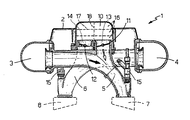
図面において、図1は本発明に係る車両内燃機関用可変容量吸入システムの概略平面図を示し、図2は図1のII−IIに沿う断面図を示す。
【0011】
図1及び図2の符号1は公知の車両(図示せず)、例えばGTカー用の内燃機関(図示せず)の他の点は公知の可変容量吸入システムを示す。吸入システム1は2つの容量3、4及び吸入管5、6からなっている。容量3、4はエンジンのシリンダヘッド2に装着されており、シリンダヘッド2の各側に対向して設けられている。吸入管5、6は、容量3、4に平行に設けられている2つのインラインブロック(それらのうち1つのシリンダ7及び1つのシリンダ8のみが示されている)のそれぞれのシリンダ7、8に容量3、4を連通している。容量3、4は更に公知の方法により(詳細は図示せず)空気供給源に連結されており、この空気供給源は、例えば、それぞれ導管9からなっていて公知のエアフィルタ(図示せず)に接続されている。
【0012】
本発明によると、吸入システムは更に付加的な容量10を含んでおり、この容量10はシリンダヘッド2に形成された閉じた部屋の形状をしており、容量3、4の間で且つ吸入管5、6の上方にあり、そして容量3、4の全長に沿って平行に延びている。本発明の吸入システム1は、オン−オフバルブ手段11、12を含んでおり、このバルブ手段11、12は吸入管5、6を選択的にそれぞれの容量3、4のみならず付加的な容量10に連結する。
【0013】
図示した好ましい実施例においては、吸入管5、6は曲った軸線となっており、そして互いに平行しそして容量10の内部に繋っているそれぞれの横の支管13、14とともにY形状をしている。容量10に連結するためのバルブ手段11、12は支管13、14の内部に公知の方法で装着された絞り弁からなっている。そして第1のブロックのそれぞれのシリンダ7の吸入管5は第2のブロックのそれぞれのシリンダ8の吸入管と交差している。すなわち、シリンダヘッド2の一側にある吸入管5は反対側においてブロックのシリンダ内に連通しており、吸入管6については反対となっている。
【0014】
Y部分の下流に、すなわち、それぞれの支管13、14の下流において、吸入管5、6にはそれぞれ燃料インジェクタ15が装着されている。
【0015】
1つの変態様においては、オン−オフバルブ手段11、12は、付加的な容量10の内部において吸入管5、6の入口断面をエンジン速度の関数として連続的に変化させるバルブ(例えばその全行程において連続的に制御される絞り弁)などに置換えることもできる。この場合に、閉じられた部屋で構成する代りに、容量10は容量3、4及び/又は空気供給手段10に油圧的に連結された部屋でなければならない。
【0016】
更に他の変態様においては、添付図面に破線で示すように、容量10は仕切り17により多数の横断面室16に分離されており、それにより各シリンダ7、8に別個に供給するようにし、または長手方向仕切り18によりそれぞれブロックに連結された2つの分離した部屋に分けられ、シリンダ7、8の2つのブロックに対し異なった供給システムを使用することを可能としている。
【0017】
実際の使用に際して、絞り弁11、12が図示したように閉じられたときに、支管13、14は閉じられ、そしてシリンダ7、8の各ブロックに対して、吸入行程における吸入システム1の容積はそれぞれの容量3、4の容積と各ブロックに提供されている単一の吸入管5、6の容積との和になる。これにより吸入管5、6は設計段階において吸入システム1の所定のエンジン速度において吸入システム1が同調条件となるように設計され、それによりエンジン効率を最適とする。
【0018】
バルブ手段11、12が(同時または別個に)開かれるときには、シリンダ7、8のブロックに連通しているシステム1の容積は付加的な容量10の容積に等しい量だけ増加して同調条件を変化させる。付加的な容量10の容積は勿論前述したエンジン速度以外の同調条件を決定するように計算されており、それにより単に絞り弁11、12を制御することにより最適な同調条件が2つの異なった所定のエンジン速度に対して達成でき、異なる速度におけるエンジンの全容積効率が向上する。
【0019】
【発明の効果】
本発明によれば、所定のエンジン速度においてシステムの同調条件を決定することによりエンジン吸入量を最適とし、そして同時に直接的であって丈夫な設計で且つ信頼性を高度に高める可変容量吸入システムが提供される。
【図面の簡単な説明】
【図1】 本発明に係る車両内燃機関用可変容量吸入システムの概略平面図である。
【図2】 図1のII−IIに沿う断面図である。
【符号の説明】
1 車両内燃機関用可変容量吸入システム
3 容量
4 容量
5 吸入管
6 吸入管
7 シリンダ
8 シリンダ
10 付加的な容量
11 バルブ手段
12 バルブ手段
13 横の支管
14 横の支管
15 燃料インジェクタ
16 横断室
17 壁面
Claims (6)
- a)第1のシリンダ(7)への供給に適した多数の第1の吸入管(5)、及び第2のシリンダ(8)への供給に適した多数の第2の吸入管(6);
b)その内部に前記第1の吸入管(5)が接続されるとともに空気供給源(9)に連結された第1の容量(3);
c)その内部に前記第2の吸入管(6)が接続されるとともに空気供給源(9)に連結された第2の容量(4);
d)前記第1及び第2の容量(3、4)の間に位置された付加的な容量(10);
e)前記付加的な容量(10)の少なくとも一部を前記吸入管(5、6)の各々に選択的に連結するためのバルブ手段(11、12);
からなる車両内燃機関用可変容量吸入システムであって、
f)前記第1及び第2の吸入管(5、6)はそれぞれ互いに独立していて、それぞれ前記第1及び第2の容量(3、4)に連結されている以外に、互いに連結されておらず、それらは前記バルブ手段(11、12)を介して前記付加的な容量(10)に連結されており;
g)前記第1及び第2の吸入管(5、6)は曲って互いに交差していて、前記第1及び第2の吸入管(5、6)の各々は前記それぞれが接続される前記容量(3、4)と反対側にあるシリンダ(7、8)に接続されており;
h)前記吸入管(5、6)が、互いに平行で且つ前記付加的な容量(10)に接続した横の支管(13、14)とともにY形状をしており、該横の支管(13、14)が内部に前記バルブ手段(11、12)を具備している;
車両内燃機関用可変容量吸入システム(1)において、
i)前記付加的な容量(10)が閉じた部屋からなり;
j)前記第1の横の支管(13)が前記第2の横の支管(14)に関して前記第1の容量(3)と反対側で前記付加的な容量(10)の内部に接続され;前記第2の横の支管(14)が前記第1の横の支管(13)に関して前記第2の容量(4)で反対側の前記付加的な容量(10)の内部に接続されている;
ことを特徴とする車両内燃機関用可変容量吸入システム(1)。 - 前記第1及び第2の横の支管(13、14)が互いに平行するとともに前記付加的な容量(10)の内部で互いに横方向に間隔を開けており;前記第1の吸入管(5)の前記第1の横の支管(13)が前記第2の容量(4)の側に位置するとともに前記第1の容量(3)とは反対側において前記付加的な容量(10)内に接続され;前記第2の吸入管(5)の前記第2の横の支管(14)が前記第1の容量(3)の側に位置するとともに前記第2の容量(4)とは反対側において前記付加的な容量(10)内に接続され;前記第2の横の支管(14)の接続部が位置する付加的な容量(10)の部分が前記第1の横の支管(13)接続部が位置する付加的な容量(10)の部分と隣接していることを特徴とする請求項1に記載の可変容量吸入システム(1)。
- 前記バルブ手段(11、12)が絞り弁であることを特徴とする請求項2に記載の可変容量吸入システム(1)。
- 燃料インジェクタ(15)が前記吸入管(5、6)の各々のY部分の下流に設けられていることを特徴とする請求項3に記載の可変容量吸入システム(1)。
- 前記付加的な容量(10)が該付加的な容量(10)をそれぞれシリンダ(7、8)に対応した2つの分離した部屋に分離している長手方向の仕切り(18)を含んでいることを特徴とする請求項4に記載の可変容量吸入システム(1)。
- 前記付加的な容量(10)が対応する壁面(17)により多数の横断室(16)に分離されており;各横断室(16)はそれぞれシリンダ(7、8)に連結されていることを特徴とする請求項4に記載の可変容量吸入システム(1)。
Applications Claiming Priority (2)
| Application Number | Priority Date | Filing Date | Title |
|---|---|---|---|
| IT095A000837 | 1995-10-17 | ||
| IT95TO000837A IT1280979B1 (it) | 1995-10-17 | 1995-10-17 | Sistema di aspirazione a capacita' variabile per un motore endotermico di un veicolo |
Publications (2)
| Publication Number | Publication Date |
|---|---|
| JPH09203321A JPH09203321A (ja) | 1997-08-05 |
| JP4227202B2 true JP4227202B2 (ja) | 2009-02-18 |
Family
ID=11413893
Family Applications (1)
| Application Number | Title | Priority Date | Filing Date |
|---|---|---|---|
| JP29458396A Expired - Fee Related JP4227202B2 (ja) | 1995-10-17 | 1996-10-16 | 車両内燃機関用可変容量吸入システム |
Country Status (6)
| Country | Link |
|---|---|
| US (1) | US5890464A (ja) |
| EP (1) | EP0769609B1 (ja) |
| JP (1) | JP4227202B2 (ja) |
| DE (1) | DE69610392T2 (ja) |
| ES (1) | ES2150058T3 (ja) |
| IT (1) | IT1280979B1 (ja) |
Families Citing this family (12)
| Publication number | Priority date | Publication date | Assignee | Title |
|---|---|---|---|---|
| US6718930B2 (en) * | 2001-07-23 | 2004-04-13 | Suzuki Motor Corporation | Intake system of a V-type engine |
| USD465790S1 (en) | 2002-01-10 | 2002-11-19 | Gerald L. Magnuson | Universal intake manifold tub for general motors LS-1/GEN 3 vortec engines |
| JP4103424B2 (ja) * | 2002-03-28 | 2008-06-18 | アイシン精機株式会社 | エンジンの吸気装置 |
| WO2004009975A1 (en) | 2002-07-19 | 2004-01-29 | Litens Automotive | Intake manifold having variable cross-sectional area |
| US7281512B2 (en) * | 2003-06-23 | 2007-10-16 | Siemens Vdo Automotive, Inc. | Passively variable plenum volume for a vehicle intake manifold assembly |
| US6837204B1 (en) * | 2003-06-23 | 2005-01-04 | Siemens Vdo Automotive Inc. | Continuously variable intake manifold with an adjustable plenum |
| US7073473B2 (en) * | 2003-07-18 | 2006-07-11 | Litens Automotive Partnership | Intake manifold variable runner area |
| DE10336196A1 (de) * | 2003-08-07 | 2005-03-03 | Daimlerchrysler Ag | Saugmodul für eine Brrennkraftmaschine |
| US7004137B2 (en) * | 2003-12-10 | 2006-02-28 | Nissan Motors Co., Ltd | V-type multiple-cylinder air intake device |
| US6986333B2 (en) * | 2004-05-25 | 2006-01-17 | Litens Automotive | Intake manifold with variable runner area |
| US7370620B1 (en) * | 2005-04-07 | 2008-05-13 | Hayes Lemmerz International, Inc. | Intake manifold assembly having short compact runners and methods of making same |
| US20150068482A1 (en) * | 2013-09-09 | 2015-03-12 | Motive Power Industry Co., Ltd. | Kinetic system-oriented variable intake structure |
Family Cites Families (16)
| Publication number | Priority date | Publication date | Assignee | Title |
|---|---|---|---|---|
| JPS6081458A (ja) * | 1983-10-12 | 1985-05-09 | Yamaha Motor Co Ltd | エンジンの吸気装置 |
| US4765285A (en) * | 1985-08-07 | 1988-08-23 | Yamaha Hatsudoki Kabushiki Kaisha | Intake system for internal combustion engine |
| IT206482Z2 (it) * | 1985-10-11 | 1987-08-10 | Fiat Auto Spa | Collettore di aspirazione per motori a combustione interna particolarmente motori a combustione internaper autoveicoli |
| JPH07101008B2 (ja) * | 1986-01-14 | 1995-11-01 | ヤマハ発動機株式会社 | 多気筒エンジンの吸気装置 |
| JPH089969B2 (ja) * | 1988-06-06 | 1996-01-31 | 日産自動車株式会社 | V型8気筒機関の可変吸気装置 |
| US4957071A (en) * | 1988-07-26 | 1990-09-18 | Nissan Motor Co., Ltd. | Intake system for V-type internal combustion engine |
| JP2759461B2 (ja) * | 1988-10-12 | 1998-05-28 | ヤマハ発動機株式会社 | エンジンの吸気装置 |
| JP2767441B2 (ja) * | 1988-11-25 | 1998-06-18 | ヤマハ発動機株式会社 | V型多気筒エンジンの吸気装置 |
| JP2777817B2 (ja) * | 1989-04-20 | 1998-07-23 | ヤマハ発動機株式会社 | 多気筒エンジンの吸気装置 |
| JPH0315621A (ja) * | 1989-06-13 | 1991-01-24 | Mazda Motor Corp | エンジンの吸気装置 |
| JPH06105042B2 (ja) * | 1989-06-30 | 1994-12-21 | マツダ株式会社 | エンジンの吸気装置 |
| JPH03130527A (ja) * | 1989-10-12 | 1991-06-04 | Fuji Heavy Ind Ltd | エンジンの可変吸気制御装置 |
| US5127370A (en) * | 1990-03-20 | 1992-07-07 | Yamaha Hatsudoki Kabushiki Kaisha | Induction system for V type engine |
| JPH05280350A (ja) * | 1992-03-31 | 1993-10-26 | Suzuki Motor Corp | V型エンジンの吸気装置 |
| JPH06280576A (ja) * | 1993-03-25 | 1994-10-04 | Mazda Motor Corp | エンジンの吸気装置 |
| JP3015621U (ja) | 1995-03-09 | 1995-09-05 | 英人 新海 | カード状物のホルダー |
-
1995
- 1995-10-17 IT IT95TO000837A patent/IT1280979B1/it active IP Right Grant
-
1996
- 1996-10-16 ES ES96116609T patent/ES2150058T3/es not_active Expired - Lifetime
- 1996-10-16 DE DE69610392T patent/DE69610392T2/de not_active Expired - Lifetime
- 1996-10-16 EP EP96116609A patent/EP0769609B1/en not_active Expired - Lifetime
- 1996-10-16 JP JP29458396A patent/JP4227202B2/ja not_active Expired - Fee Related
- 1996-10-17 US US08/734,392 patent/US5890464A/en not_active Expired - Lifetime
Also Published As
| Publication number | Publication date |
|---|---|
| ES2150058T3 (es) | 2000-11-16 |
| IT1280979B1 (it) | 1998-02-11 |
| ITTO950837A1 (it) | 1997-04-17 |
| DE69610392T2 (de) | 2001-05-23 |
| EP0769609B1 (en) | 2000-09-20 |
| JPH09203321A (ja) | 1997-08-05 |
| DE69610392D1 (de) | 2000-10-26 |
| EP0769609A1 (en) | 1997-04-23 |
| US5890464A (en) | 1999-04-06 |
| ITTO950837A0 (ja) | 1995-10-17 |
Similar Documents
| Publication | Publication Date | Title |
|---|---|---|
| JP3353191B2 (ja) | 多気筒v型エンジン | |
| CA1278963C (en) | Intake manifold assembly for engines | |
| US4765285A (en) | Intake system for internal combustion engine | |
| US4741294A (en) | Inertia supercharging induction system for multi-cylinder internal combustion engine | |
| EP0769609B1 (en) | Variable-capacity intake system for a vehicle internal combustion engine | |
| US4727829A (en) | Intake system for internal combustion engine | |
| EP0769608B1 (en) | Internal combustion engine with variable-capacity intake system for a vehicle | |
| JPH03281927A (ja) | エンジンの吸気装置 | |
| JP3936760B6 (ja) | 車両内燃機関用可変容量吸入システム | |
| EP0870102B1 (en) | Flap valve for intake system for an internal combustion engine | |
| JPH06159072A (ja) | 内燃機関の可変吸気システム | |
| JPH0694811B2 (ja) | 多気筒エンジンの吸気装置 | |
| JP2772674B2 (ja) | V型多気筒内燃機関における吸気装置 | |
| JPH0141905Y2 (ja) | ||
| JPS60198321A (ja) | V型エンジンの吸気装置 | |
| JPH029090Y2 (ja) | ||
| JPH039023A (ja) | 多気筒内燃機関の吸気装置 | |
| JPH0629559B2 (ja) | 多気筒エンジンの吸気装置 | |
| JPH1037750A (ja) | 内燃機関の吸気制御装置 | |
| JP2552478B2 (ja) | V型エンジンの排気装置 | |
| JPH0729224Y2 (ja) | V型内燃機関の吸気装置 | |
| JPH0738661Y2 (ja) | エンジンの吸気装置 | |
| JPH109071A (ja) | 多気筒内燃機関の吸気装置 | |
| JPH04164121A (ja) | エンジンの吸気装置 | |
| JPH051545A (ja) | 内燃機関の吸気装置 |
Legal Events
| Date | Code | Title | Description |
|---|---|---|---|
| A621 | Written request for application examination |
Free format text: JAPANESE INTERMEDIATE CODE: A621 Effective date: 20030910 |
|
| A131 | Notification of reasons for refusal |
Free format text: JAPANESE INTERMEDIATE CODE: A131 Effective date: 20060711 |
|
| A601 | Written request for extension of time |
Free format text: JAPANESE INTERMEDIATE CODE: A601 Effective date: 20061010 |
|
| A602 | Written permission of extension of time |
Free format text: JAPANESE INTERMEDIATE CODE: A602 Effective date: 20061013 |
|
| A521 | Request for written amendment filed |
Free format text: JAPANESE INTERMEDIATE CODE: A821 Effective date: 20061219 |
|
| A521 | Request for written amendment filed |
Free format text: JAPANESE INTERMEDIATE CODE: A523 Effective date: 20061219 |
|
| A02 | Decision of refusal |
Free format text: JAPANESE INTERMEDIATE CODE: A02 Effective date: 20070306 |
|
| A521 | Request for written amendment filed |
Free format text: JAPANESE INTERMEDIATE CODE: A523 Effective date: 20070611 Free format text: JAPANESE INTERMEDIATE CODE: A821 Effective date: 20070611 |
|
| A911 | Transfer to examiner for re-examination before appeal (zenchi) |
Free format text: JAPANESE INTERMEDIATE CODE: A911 Effective date: 20070710 |
|
| A912 | Re-examination (zenchi) completed and case transferred to appeal board |
Free format text: JAPANESE INTERMEDIATE CODE: A912 Effective date: 20070914 |
|
| A601 | Written request for extension of time |
Free format text: JAPANESE INTERMEDIATE CODE: A601 Effective date: 20080616 |
|
| A602 | Written permission of extension of time |
Free format text: JAPANESE INTERMEDIATE CODE: A602 Effective date: 20080619 |
|
| A601 | Written request for extension of time |
Free format text: JAPANESE INTERMEDIATE CODE: A601 Effective date: 20080716 |
|
| A602 | Written permission of extension of time |
Free format text: JAPANESE INTERMEDIATE CODE: A602 Effective date: 20080722 |
|
| A601 | Written request for extension of time |
Free format text: JAPANESE INTERMEDIATE CODE: A601 Effective date: 20080813 |
|
| A602 | Written permission of extension of time |
Free format text: JAPANESE INTERMEDIATE CODE: A602 Effective date: 20080818 |
|
| A521 | Request for written amendment filed |
Free format text: JAPANESE INTERMEDIATE CODE: A523 Effective date: 20080917 Free format text: JAPANESE INTERMEDIATE CODE: A821 Effective date: 20080917 |
|
| A521 | Request for written amendment filed |
Free format text: JAPANESE INTERMEDIATE CODE: A821 Effective date: 20080917 |
|
| A01 | Written decision to grant a patent or to grant a registration (utility model) |
Free format text: JAPANESE INTERMEDIATE CODE: A01 |
|
| A61 | First payment of annual fees (during grant procedure) |
Free format text: JAPANESE INTERMEDIATE CODE: A61 Effective date: 20081128 |
|
| FPAY | Renewal fee payment (event date is renewal date of database) |
Free format text: PAYMENT UNTIL: 20111205 Year of fee payment: 3 |
|
| R150 | Certificate of patent or registration of utility model |
Free format text: JAPANESE INTERMEDIATE CODE: R150 |
|
| FPAY | Renewal fee payment (event date is renewal date of database) |
Free format text: PAYMENT UNTIL: 20111205 Year of fee payment: 3 |
|
| FPAY | Renewal fee payment (event date is renewal date of database) |
Free format text: PAYMENT UNTIL: 20121205 Year of fee payment: 4 |
|
| FPAY | Renewal fee payment (event date is renewal date of database) |
Free format text: PAYMENT UNTIL: 20131205 Year of fee payment: 5 |
|
| LAPS | Cancellation because of no payment of annual fees |