WO1999002328A1 - Method of producing thermoplastic resin film and apparatus for producing the same - Google Patents
Method of producing thermoplastic resin film and apparatus for producing the same Download PDFInfo
- Publication number
- WO1999002328A1 WO1999002328A1 PCT/JP1998/003087 JP9803087W WO9902328A1 WO 1999002328 A1 WO1999002328 A1 WO 1999002328A1 JP 9803087 W JP9803087 W JP 9803087W WO 9902328 A1 WO9902328 A1 WO 9902328A1
- Authority
- WO
- WIPO (PCT)
- Prior art keywords
- thermoplastic resin
- resin film
- film
- medium
- cooling medium
- Prior art date
- Legal status (The legal status is an assumption and is not a legal conclusion. Google has not performed a legal analysis and makes no representation as to the accuracy of the status listed.)
- Ceased
Links
Classifications
-
- B—PERFORMING OPERATIONS; TRANSPORTING
- B29—WORKING OF PLASTICS; WORKING OF SUBSTANCES IN A PLASTIC STATE IN GENERAL
- B29C—SHAPING OR JOINING OF PLASTICS; SHAPING OF MATERIAL IN A PLASTIC STATE, NOT OTHERWISE PROVIDED FOR; AFTER-TREATMENT OF THE SHAPED PRODUCTS, e.g. REPAIRING
- B29C39/00—Shaping by casting, i.e. introducing the moulding material into a mould or between confining surfaces without significant moulding pressure; Apparatus therefor
- B29C39/22—Component parts, details or accessories; Auxiliary operations
- B29C39/38—Heating or cooling
-
- B—PERFORMING OPERATIONS; TRANSPORTING
- B29—WORKING OF PLASTICS; WORKING OF SUBSTANCES IN A PLASTIC STATE IN GENERAL
- B29C—SHAPING OR JOINING OF PLASTICS; SHAPING OF MATERIAL IN A PLASTIC STATE, NOT OTHERWISE PROVIDED FOR; AFTER-TREATMENT OF THE SHAPED PRODUCTS, e.g. REPAIRING
- B29C33/00—Moulds or cores; Details thereof or accessories therefor
- B29C33/02—Moulds or cores; Details thereof or accessories therefor with incorporated heating or cooling means
- B29C33/04—Moulds or cores; Details thereof or accessories therefor with incorporated heating or cooling means using liquids, gas or steam
- B29C33/044—Moulds or cores; Details thereof or accessories therefor with incorporated heating or cooling means using liquids, gas or steam in rolls calenders or drums
-
- B—PERFORMING OPERATIONS; TRANSPORTING
- B29—WORKING OF PLASTICS; WORKING OF SUBSTANCES IN A PLASTIC STATE IN GENERAL
- B29C—SHAPING OR JOINING OF PLASTICS; SHAPING OF MATERIAL IN A PLASTIC STATE, NOT OTHERWISE PROVIDED FOR; AFTER-TREATMENT OF THE SHAPED PRODUCTS, e.g. REPAIRING
- B29C48/00—Extrusion moulding, i.e. expressing the moulding material through a die or nozzle which imparts the desired form; Apparatus therefor
- B29C48/03—Extrusion moulding, i.e. expressing the moulding material through a die or nozzle which imparts the desired form; Apparatus therefor characterised by the shape of the extruded material at extrusion
- B29C48/07—Flat, e.g. panels
- B29C48/08—Flat, e.g. panels flexible, e.g. films
-
- B—PERFORMING OPERATIONS; TRANSPORTING
- B29—WORKING OF PLASTICS; WORKING OF SUBSTANCES IN A PLASTIC STATE IN GENERAL
- B29C—SHAPING OR JOINING OF PLASTICS; SHAPING OF MATERIAL IN A PLASTIC STATE, NOT OTHERWISE PROVIDED FOR; AFTER-TREATMENT OF THE SHAPED PRODUCTS, e.g. REPAIRING
- B29C48/00—Extrusion moulding, i.e. expressing the moulding material through a die or nozzle which imparts the desired form; Apparatus therefor
- B29C48/25—Component parts, details or accessories; Auxiliary operations
- B29C48/88—Thermal treatment of the stream of extruded material, e.g. cooling
- B29C48/911—Cooling
- B29C48/9135—Cooling of flat articles, e.g. using specially adapted supporting means
- B29C48/914—Cooling drums
-
- B—PERFORMING OPERATIONS; TRANSPORTING
- B29—WORKING OF PLASTICS; WORKING OF SUBSTANCES IN A PLASTIC STATE IN GENERAL
- B29C—SHAPING OR JOINING OF PLASTICS; SHAPING OF MATERIAL IN A PLASTIC STATE, NOT OTHERWISE PROVIDED FOR; AFTER-TREATMENT OF THE SHAPED PRODUCTS, e.g. REPAIRING
- B29C33/00—Moulds or cores; Details thereof or accessories therefor
- B29C33/02—Moulds or cores; Details thereof or accessories therefor with incorporated heating or cooling means
- B29C33/04—Moulds or cores; Details thereof or accessories therefor with incorporated heating or cooling means using liquids, gas or steam
- B29C33/046—Moulds or cores; Details thereof or accessories therefor with incorporated heating or cooling means using liquids, gas or steam using gas
-
- B—PERFORMING OPERATIONS; TRANSPORTING
- B29—WORKING OF PLASTICS; WORKING OF SUBSTANCES IN A PLASTIC STATE IN GENERAL
- B29C—SHAPING OR JOINING OF PLASTICS; SHAPING OF MATERIAL IN A PLASTIC STATE, NOT OTHERWISE PROVIDED FOR; AFTER-TREATMENT OF THE SHAPED PRODUCTS, e.g. REPAIRING
- B29C48/00—Extrusion moulding, i.e. expressing the moulding material through a die or nozzle which imparts the desired form; Apparatus therefor
- B29C48/25—Component parts, details or accessories; Auxiliary operations
- B29C48/88—Thermal treatment of the stream of extruded material, e.g. cooling
- B29C48/911—Cooling
- B29C48/9135—Cooling of flat articles, e.g. using specially adapted supporting means
- B29C48/915—Cooling of flat articles, e.g. using specially adapted supporting means with means for improving the adhesion to the supporting means
- B29C48/9165—Electrostatic pinning
-
- B—PERFORMING OPERATIONS; TRANSPORTING
- B29—WORKING OF PLASTICS; WORKING OF SUBSTANCES IN A PLASTIC STATE IN GENERAL
- B29C—SHAPING OR JOINING OF PLASTICS; SHAPING OF MATERIAL IN A PLASTIC STATE, NOT OTHERWISE PROVIDED FOR; AFTER-TREATMENT OF THE SHAPED PRODUCTS, e.g. REPAIRING
- B29C48/00—Extrusion moulding, i.e. expressing the moulding material through a die or nozzle which imparts the desired form; Apparatus therefor
- B29C48/25—Component parts, details or accessories; Auxiliary operations
- B29C48/88—Thermal treatment of the stream of extruded material, e.g. cooling
- B29C48/911—Cooling
- B29C48/9135—Cooling of flat articles, e.g. using specially adapted supporting means
- B29C48/9175—Cooling of flat articles, e.g. using specially adapted supporting means by interposing a fluid layer between the supporting means and the flat article
Definitions
- the present invention relates to a method for producing a thermoplastic resin film, and an apparatus for producing a thermoplastic resin film suitable for performing the method.
- a method for producing a thermoplastic resin film is to rapidly cool a thermoplastic resin film melt-extruded from a die to a temperature lower than a glass transition temperature of the resin by closely contacting the film with a cooling drum and cooling the film.
- a cast film with low transparency, good transparency, and a smooth surface was prepared, and if necessary, stretched uniaxially or biaxially.
- the maximum speed at which a molten thermoplastic resin film is brought into close contact with a cooling drum and quenched to obtain a film with low crystallinity and a transparent and smooth surface is as follows: electrostatic application method, vacuum suction method, press method Even if all casting means effective for high-speed casting such as are used, it is not possible to prevent air from entering between the cast film and the cooling drum, so make the speed faster than about 40 to 60 m / min. I could't do that, and I had to be productive.
- the present invention solves the above-mentioned disadvantages, and provides a production method capable of obtaining a thermoplastic resin film excellent in both productivity and quality, and a thermoplastic resin film suitable for carrying out the production method.
- An object of the present invention is to provide a manufacturing apparatus.
- thermoplastic resin film of the present invention that achieves the above-mentioned object is characterized in that when a molten thermoplastic resin film is brought into close contact with a cooling medium and cooled and solidified to produce a cast film, A method for producing a thermoplastic resin film, characterized in that the method is carried out in a state where the surface temperature of a cooling medium is maintained in a range of a glass transition temperature Tg or more and a melting point Tm or less of the thermoplastic resin.
- thermoplastic resin film of the present invention is a method for producing a cast film by bringing a molten thermoplastic resin film into close contact with a cooling medium and cooling and solidifying the film.
- the surface temperature of the cooling medium immediately before the melt is grounded is within the range of the glass transition temperature Tg of the thermoplastic resin and the melting point Tm or less, and the cooling is performed immediately before the melt is separated from the cooling medium.
- This is a method for producing a thermoplastic resin film, which is performed in a state where the surface temperature of the medium is kept below the glass transition temperature Tg of the thermoplastic resin.
- the surface temperature of the cooling medium immediately before the grounding of the melt is not less than the glass transition temperature Tg and not more than the melting point Tm of the thermoplastic resin.
- the cooling medium has a heating device and a cooling device so that the surface temperature of the cooling medium immediately before the resin is separated from the cooling medium can be kept within a range of less than the glass transition temperature Tg of the thermoplastic resin.
- the surface temperature of a cooling medium such as a casting drum, with which the melt contacts is set to a temperature equal to or higher than the Tg of the polymer.
- the film temperature is lower than the Tg of the resin, or the film is peeled off after crystallization on a cooling medium, producing a film with the following excellent productivity and excellent film characteristics. You can do it.
- FIG. 1 is a schematic perspective view illustrating an example of the structure of an external heating system that can be used in the thermoplastic resin film manufacturing apparatus of the present invention.
- FIG. 2 is a sectional view of a central portion of the external heating system shown in FIG.
- FIG. 3 is a schematic perspective view illustrating an example of the structure of an internal liquid heating system that can be used in the thermoplastic resin film manufacturing apparatus of the present invention.
- FIG. 4 is a sectional view of a central portion of the internal liquid heating system shown in FIG.
- FIG. 5 is an end sectional view of the internal liquid heating system shown in FIG.
- FIG. 6 is a cross-sectional view of a central portion illustrating an example of a structure of an internal heating embedding method that can be used in the thermoplastic resin film manufacturing apparatus of the present invention.
- FIG. 7 is an axial sectional view of the internal heating embedding method shown in FIG.
- FIG. 8 is a side view of the internal heating embedding method shown in FIG.
- FIG. 9 is a schematic perspective view illustrating the structure of an example of a belt heating method that can be used in the thermoplastic resin film manufacturing apparatus of the present invention.
- FIG. 10 is a schematic diagram showing the inside of a conventional cooling heat medium.
- FIG. 11 is a schematic sectional view showing the internal structure of a conventional cooling heat medium.
- the thermoplastic resin is a resin that exhibits fluidity when heated, and includes a resin selected from polyester, polyamide, polyolefin, polyphenylene sulfide, vinyl polymer, and a mixture or modified product thereof. It is a typical resin, and in the case of the present invention, a polyester resin, a polyamide resin, etc. Is particularly preferred.
- Polyester is a polymer compound having an ester bond in the main molecular chain, and is usually synthesized by polycondensation reaction between divinyl and dicarboxylic acid.
- a compound that self-condenses such as a hydroxycarboxylic acid represented by the following formula, may be used.
- diol compounds include ethylene glycol, propylene glycol, butylene glycol, hexene glycol represented by HO (CH 2 ) n OH, and diethylene glycol, polyethylene glycol, and ethylene chloride adduct. And ether-containing dials typified by propylene-based adducts and the like, alone or as a mixture thereof.
- dicarboxylic acid compounds include phthalic acid, isophthalic acid, terephthalic acid, naphthalene dicarboxylic acid, succinic acid, adipic acid, pimelic acid, suberic acid, azelaic acid, sebacic acid, dimeric acid, Maleic acid, fumaric acid, and mixtures thereof.
- PET polyethylene terephthalate
- PBN polybutylene naphthalate
- PBT polybutylene terephthalate
- the number of repeating units of these polymer compounds is preferably 80 or more, and more preferably 120 or more.
- the intrinsic viscosity is preferably 0.4 (dI / g) or more, and more preferably 0.55 (dI / g) or more, as measured in orthochlorophenol (OCP).
- OCP orthochlorophenol
- the raw material has a low intrinsic viscosity of about 0.2 to 0.5, or a raw material mixed with another raw material is used as it is.
- additives such as a crystal nucleating agent, a slipping agent, a stabilizer, an antioxidant, a viscosity modifier, an antistatic agent, a colorant, and a pigment can be appropriately used in combination with these polymer compounds. .
- crystallization nucleus materials include talc, kaolin, silicon oxide, alumina oxide, antimony oxide, titanium oxide, zinc oxide, clay, calcium carbonate, barium sulfate, strontium sulfate, zinc oxide, magnesium hydroxide, and calcium silicate , Diatomaceous earth, carbon black and other inorganic compounds, and Ionomers, for example, metal salts of aliphatic carboxylic acids ⁇ sulfonic acid represented by ethylene methacrylic acid, aromatic sulfonic acid represented by styrene sulfonic acid, and metal salts of carboxylic acid (metal species include Na And alkali metal salts such as Li, alkaline earth metals represented by Zn, Ca, and Ba), and organic compounds such as liquid crystalline polyester compounds. Needless to say, the crystallization speed of a metal salt obtained by reacting a polyester molecule end with an alkali metal salt such as sodium salt also increases.
- the liquid crystalline polyester is a polyester having a mesogenic group and exhibiting optical anisotropy when melted.
- a typical liquid crystalline polyester compound is disclosed in JP-A-7-233310. It is represented by a gazette or the like.
- the liquid crystalline polyester is particularly preferably a liquid crystalline polyester containing 40 to 90% by weight of a parahydroxydibenzoic acid (HBA) component as a main mesogen.
- HBA parahydroxydibenzoic acid
- the mesogen content may be in any form, such as random copolymerization, block copolymerization, branch copolymerization, or a combination thereof, but in the case of the present invention, in particular, in the case of random copolymerization and block copolymerization, Complexes are preferred.
- the melt viscosity ⁇ ⁇ of the liquid crystalline polyester is 100 Pa ⁇ s or less, preferably 20 Pa ⁇ s or less, more preferably 10 Pa ⁇ s or less. It is good in that it can promote the effects of the invention.
- the liquid crystalline polyester is contained in the polyester film in an amount of 0.01 to 5%, preferably 0.1 to 1%.
- the content of the liquid crystalline polyester exceeds 5%, the physical properties of the polyester film, such as transparency, tear propagation resistance, impact properties, and abrasion properties, decrease. On the other hand, if the content is less than 0.01%, the effects of the present invention such as the crystallization promoting effect and the improvement in stretchability cannot be achieved well.
- the liquid crystalline polyester is dispersed in the polyester film in a thickness direction of 0.5 kim or less, preferably 0.3 ⁇ or less, more preferably 0.5 ⁇ or less, in the form of a layer or needle.
- the polyamide resin is a high molecular compound having an amide bond in the main chain, and typical examples are nylon 6, nylon 66, nylon 106, nylon 1 2, Nylon 11, Nylon 7, Polymeta / paraxylylene adipamide, Polyhexamethylene terephthalamide / Isofuran amide, and their related copolymers, blends and other polyamide compounds Can be used.
- these may be polyamide ether compounds obtained by copolymerizing polyether compounds such as polyethylene glycol, polypropylene glycol, and polytetramethylene glycol, and polyester amide compounds copolymerized with polyester.
- polyether compounds such as polyethylene glycol, polypropylene glycol, and polytetramethylene glycol
- polyester amide compounds copolymerized with polyester In the case of the present invention, In particular, it has a particularly excellent effect on a multi-component copolymer which is hardly crystallized, and an amorphous polyamide resin having many or large substituents in a side chain.
- polyphenylene disulfide resin a linear compound substantially free of a branched structure is preferably used.
- the surface temperature of the medium immediately before grounding of the melt should be equal to or higher than the glass transition temperature Tg of the thermoplastic resin, and the melting point T By setting it to m or less, high-speed cast film formation without air injection becomes possible, and a thermoplastic resin film excellent in both productivity and quality can be manufactured.
- the surface temperature of the cooling medium was Tg or more
- the cast film could not be peeled off smoothly and smoothly from the cooling medium due to its large adhesive force, and as a result, the obtained film was obtained.
- the flatness of the film often deteriorates extremely or becomes difficult to peel.
- the casting temperature of a normal polyester resin film is brought into close contact with a cooling drum or the like heated to a temperature higher than the glass transition temperature Tg, the adhesion becomes large. However, this makes it difficult to remove the film from the drum, which also prevents casting.
- the important point of the present invention is that, first, the molten thermoplastic resin film is landed on a cooling drum heated at least at the surface temperature of the resin to the glass transition temperature T g or more, thereby forming a drum. It enhances the adhesion to the molten film, prevents air entrapment such as entrained airflow, and achieves high-speed casting. Without it, high-speed casting is difficult to achieve.
- thermoplastic resin A heating / cooling method that enables the cast film to be peeled from the cooling medium by lowering the adhesive force by setting the surface temperature of the medium immediately before peeling to less than the glass transition temperature Tg of the thermoplastic resin
- the surface temperature of the medium immediately before the grounding of the melt is not less than the glass transition temperature Tg of the thermoplastic resin and not more than the melting point Tm, and the surface temperature of the medium immediately before the peeling is performed. It is effective to equip the cooling medium with a heating device and a cooling device so as to keep the temperature below the glass transition temperature T g of the thermoplastic resin.
- an external heating device for heating the medium surface immediately before the grounding of the melt from the medium surface immediately after the peeling of the molten thermoplastic resin film.
- FIGS. 1 and 2 show specific examples of the structure of this external heating method.
- Extrusion molding die 3 for spreading molten thermoplastic resin in film form, cooling medium 1 for cooling and solidifying molten resin spread in film form 1, cooling medium for cooled thermoplastic resin film 8 1 It consists of a peeling roll 7 for peeling off and an external heating device 2.
- the die 3 for extrusion molding is not particularly limited, and includes a T die, a coat hanger die, There is no problem if it is a flat die such as a fish tail die or a special die combining these characteristics.
- an automatic adjustment mechanism capable of controlling the thickness of the film with a computer.
- cooling water is poured from the inside of one shaft 9 and branched in, for example, six directions by a liquid heating medium branch pipe 21. It flows between 14 and the inner cylinder 13.
- a liquid heating medium branch pipe 21 By providing a multiple of the number of liquid heat medium branch pipes 21 on the surface of the inner cylinder, here, six spiral groove partition walls 16, the heat medium flows through the spiral groove 15, and again the liquid heat medium branch pipe 2 1 And is discharged from the other axis 10.
- the peeling roll 7 is not particularly limited. For example, as a surface treatment of the roll circumferential surface in contact with the thermoplastic resin film 8, after a hard chrome plating treatment is performed, a maximum surface roughness is applied. It is preferable that the mirror finish is 0.4 ⁇ or less.
- the external heating device 2 it is necessary to heat the medium surface immediately before the grounding of the melt from the medium surface immediately after the peeling of the molten thermoplastic resin film. That is, after the thermoplastic resin film cooled to T g or less peeled from the cooling medium, the surface of the cooling medium was heated by an external heating device, and came out of the die after the surface temperature became T g or more. Land the thermoplastic film.
- the external heating device 2 in the present invention one using one or a mixture of two or more selected from light irradiation, conduction, a heating heat medium, dielectric heating, combustion gas, and the like is preferable.
- a heating device having a large heat output should be selected so that there is a large difference in the surface temperature of the cooling medium 1 before and after the cooling medium 1 rotates and passes through the range of the external heating device 2.
- an infrastructure pack Infra-Pac
- a thermal jet Therma-Jet
- the film to be manufactured is not affected by wind, moisture, dust or the like generated by the external heating device 2.
- the maximum surface roughness Rt of the cooling medium 1 is preferably a mirror medium of 0.4 ⁇ or less in order to smooth the surface of the thermoplastic resin film to be molded.
- the cooling medium 1 is preferably made of a material having a thermal conductivity of 2.OW / m m to 60.OW / mK, more preferably. In other words, those having a thermal conductivity of 2.0 WZmK to 16. OWZmK are preferable. Further, it is preferable to coat a material having a thermal conductivity of 2.0 WZm K to 20.0 WZm K on the surface of the cooling medium 1.
- the coating material for example, a material obtained by spraying, plating, sputtering, or vapor-depositing ceramics, chromium, nickel, or a titanium alloy infinitely close to a black body and having a dark color is preferable. It is desirable that the space between the cooling heat medium 1 and the external heating device 2 is as close as possible to increase the energy absorption efficiency. However, considering the deformation due to heat, there is a danger that they will come into contact with each other if they are approached to a certain extent. Therefore, the interval between the two is preferably 1 to 20 Omm. More preferably, it is 5 to 5 O mm.
- the diameter of the cooling medium is ⁇ to 5 m, more preferably 1.5 to 2.5 m.
- the outer cylinder 14, the inner cylinder 13, and the hollow shafts 9, 10 are configured such that the cooling heat medium can flow from the hollow shafts 9, 10 between the outer cylinder 14 and the inner cylinder 13.
- a seal is provided between the outer cylinder and the inner cylinder near the separation of the molten thermoplastic resin film and near the ground, and inside the cooling medium 1 near the separation of the molten thermoplastic resin film 8.
- the cooling medium 1 near the ground of the melt has an internal heating device.
- the internal heating device one or more types selected from light irradiation, energization, heating heat medium, dielectric heating, combustion gas, etc. are preferable, but a method using a heat medium is particularly preferred. .
- Fig. 3 shows an external view
- Fig. 4 shows a sectional view at the center
- Fig. 5 shows a sectional view at the end of the inner cylinder of the cooling medium.
- examples of two kinds of heat medium of high temperature and low temperature are shown as the flow temperature conditions.
- the outer cylinder 14 is fixed to the rotating inner cylinder 13 and the shafts 9 and 10.
- the shafts 9 and 10 have two holes, a low-temperature heat medium pipe 30 and a high-temperature heat medium pipe 29, through which heat medium of different temperatures flows.
- the same type of heating medium is desirable so that mixing does not have any effect, and water is particularly suitable.
- the two kinds of heat mediums sent in enter one shaft 9 and flow through the gap between the inner cylinder 13 and the outer cylinder 14. Since the heat medium partition plate 19 is provided on the surface of the inner cylinder, the heat medium at high and low temperatures is difficult to mix.
- the heat medium that has passed between the inner cylinder 13 and the outer cylinder 14 is discharged from the other shaft 10 respectively.
- the inner cylinder and the outer cylinder are arbitrarily separated by a partition plate, and the flow of the heat medium is or is meandering in the circumferential direction, wherein optionally c be or is reciprocated in the width direction, as the temperature of the high temperature heat medium, not more than T g above T m, is a temperature of the low temperature heat medium T g Must be less than.
- T g temperature of the low temperature heat medium
- the position of the heat medium partition plate 19 on the surface of the inner cylinder one is preferably near the position where the thermoplastic resin film lands, and the other is near the position where the film peels off.
- This method can be used alone, but when used in combination with the external heating device 2, the surface temperature of the cooling medium 1 can be raised much higher, so that the casting can be performed at a higher speed. It becomes possible.
- a method in which the cooling liquid is not passed from the inside of the cooling medium 1 near the separation of the molten thermoplastic resin film 8 to the inside of the cooling medium 1 near the ground of the melt, that is, the heating medium is supplied to the pipe for the high-temperature heating medium May be adopted. It is preferable that the cooling heat medium is not passed through the inside of the cooling medium corresponding to the portion where the molten thermoplastic resin film is not in contact with the cooling medium, in that the surface temperature of the cooling medium is increased. That is, the liquid does not flow through the entire surface of the drum, but basically only while the molten resin film is in contact with the drum, that is, from inside the medium immediately after the molten thermoplastic resin film is grounded. However, the cooling heat medium flows only inside the medium immediately before the separation. Furthermore, since the liquid does not pass through the inside of the drum where the film is not in contact, a new heating mechanism can be installed inside the drum, so that the temperature of the drum surface of this portion is higher than that of other drum surfaces. Can also be set to high temperature.
- This heating mechanism can be appropriately selected from energization heating by an electric heater, heating by a heating heat medium, heating by dielectric loss, or a heating method by combustion gas or the like.
- the thermal conductivity is high, as opposed to that of the external heating type.
- the thermal conductivity is 30 WZ m K to 50 O WZ m K. And more preferably in the range of 30 WZm K to 100 WZm m.
- the maximum roughness of the surface of the cooling medium 1 is preferably a mirror surface of 0.4 nm or less, and the diameter of the cooling medium 1 is 1 to 5 m. More preferably, it is 1.5 to 2.5 m.
- heating devices 17 are embedded in the outer cylinder 14 of the cooling medium 1 at substantially equal intervals in the circumferential direction.
- Fig. 6 shows the specific structure. Heating devices 17 are embedded in the outer cylinder 14 of the cooling medium 1 at substantially equal intervals in the circumferential direction.
- the heating devices 17 include light irradiation, energization, a heating medium, dielectric heating, or combustion gas. One or a mixture of two or more selected from the above is preferred, but a method using an electric heater is particularly convenient and convenient.
- a power source 25 is connected to an electrode 23 extending from the vicinity of the exfoliation of the molten thermoplastic resin film 8 on one shaft 9 side to the vicinity of the ground of the molten material by using the wiring 26 and heating.
- Power is supplied to the heating device 1 via the electrode 22 on the device side, and returns to the power supply 25 through the electrode 23 and the wiring 26 of the other axis 10.
- the heating area can be changed according to the length of the electrode 23.
- an electrode is provided so that the heating device 17 generates heat only between the peeling point of the thermoplastic resin film 8 and the grounding point, and the heating device switch is turned on and off while the cooling medium makes one rotation.
- the heating device to be embedded is preferably installed as close to the surface of the cooling medium as possible.
- the thermal conductivity is high, contrary to the material of the external heating type.
- the thermal conductivity is preferably in the range of 30 OW / mK to 500 WZm ⁇ , more preferably in the range of 30 WZm ⁇ to 100 WNmK.
- the maximum roughness of the surface of the cooling medium 1 is preferably a mirror surface of 0.4 ⁇ m or less, and the diameter of the cooling medium 1 is 1 to 5 m, more preferably 1 to 5 m. .5 to 2.5 m is good.
- Cooling that includes the outer cylinder 14, the inner cylinder 13, and the hollow rotary shafts 9, 10, and allows the heat medium to flow between the outer cylinder 14 and the inner cylinder 13 from the hollow rotary shafts 9, 10.
- the surface roughness of the medium 1 and the roll 3 2 placed at a certain distance from the cooling medium 1 becomes less than 0.2 S.
- the belt is connected with a belt 18 that has been finished as described above, and a molten thermoplastic resin film 8 is formed on this belt.
- Fig. 9 shows a specific example of the structure.
- a belt 18 is stretched between the cooling medium 1 and the rolls 32 installed at a certain distance.
- the thermoplastic film 8 extruded from the extrusion die 2 lands on the belt 18 heated to Tg or more and Tm or less.
- the film 8 adheres firmly to the belt 18 due to the adhesive force of the thermoplastic resin, enabling high-speed film formation.
- the thermoplastic resin film 18 on the belt 18 is gradually cooled by cooling from the cooling medium 1, and is cooled to less than T g immediately before the peeling roll 7.
- the film 8 peeled off by the peeling roll 7 is carried to an unillustrated stretching and winding step.
- the belt 18 from which the film 8 has been removed is heated by the external heating device 2, the surface temperature is again heated to Tg or more and Tm or less, and the thermoplastic resin film 8 lands again.
- the thickness of the belt 18 is preferably as thin as possible to increase the temperature difference between before and after heating, and the thickness is preferably 0.1 to 3 mm.
- the thermal conductivity is higher than that of the external heating type.
- the thermal conductivity is preferably in the range of 30 WZ m K to 500 WZ m K, and more preferably 50 ⁇ / ⁇ 1 or more.
- the maximum roughness of the surface of the belt 18 is preferably a mirror surface of 0.4 Um or less.
- the medium surface temperature immediately before the melt is grounded is raised by at least 5 ° C or more, preferably 10 ° C or more, based on the medium surface temperature immediately after the peeling of the molten thermoplastic resin film.
- a high-speed cast can be obtained by obtaining a high adhesive strength necessary for the adhesion, and a less expensive thermoplastic resin film can be manufactured.
- the melted thermoplastic resin film is heated to a glass transition temperature Tg or more, preferably a temperature near the melt crystallization temperature Tmc. Adhering to a cooling medium such as a drum or belt, and allowing at least 5%, preferably 10% or more of the resin film to crystallize during this close contact makes it easy to peel off. It is. Therefore, this method is effective for nitro resin and polyolefin resin having a relatively high crystallization rate.
- the resulting film is a cast film with a smooth surface and excellent lubricity, and also has excellent thermal dimensional stability, and can be used at the time of slitting. There is no swelling (high edge) and the film is excellent in thermoformability.
- the casting temperature of the thermoplastic resin film is simply brought into close contact with a cooling drum or the like heated to a glass transition temperature Tg or higher and Tmc or higher, it becomes difficult to peel off from the drum and cast cannot be performed.
- an important point of the present invention is that the adhesion between the molten film and the molten film is achieved by landing the molten thermoplastic resin film on a cooling drum heated to a glass transition temperature Tg or more, preferably Tmc or more.
- Tg or more glass transition temperature
- Tmc melt crystallization temperature
- the surface crystallinity is at least 5%, preferably at least 10%. If the crystallinity of the surface layer is less than 5%, it is often difficult to peel off the cast drum.
- the cast drum temperature is set near the melt crystallization temperature Tmc of the polymer.
- Tmc melt crystallization temperature
- the film has excellent thermal dimensional stability, does not have edge ridges (high edges) during slitting, and has a favorable surface because it has excellent thermoformability. In some cases, it does not completely match the characteristics that have been used in the past, and is not preferable because of limited applications. For this reason, the method of crystallizing only the surface layer is more practical.
- the thickness of the surface layer at this time is preferably as thin as possible, preferably 1 ⁇ m or less, and more preferably 0.1 ⁇ or less.
- the crystallinity can be arbitrarily determined depending on the obtained quality, but the upper limit seems to be 30 to 50%.
- a melt obtained by laminating a thermoplastic resin film and another thermoplastic resin film having a higher crystallization rate than the thermoplastic resin film is cooled and crystallized by closely adhering a cooling drum to the resin film side at the high crystallization rate.
- the present invention can also be carried out by removing the other resin film layer having high crystallinity after solidification.
- polyethylene resin polyolefin polymer represented by polyethylene, polypropylene, ethylene propylene copolymer, methylpentene polymer, polymethylximethylene, etc.
- polyethylene resin polyolefin polymer represented by polyethylene, polypropylene, ethylene propylene copolymer, methylpentene polymer, polymethylximethylene, etc.
- Typical examples include lamination and peeling, but are not limited thereto.
- thermoplastic resin film of the present invention Next, the method for producing a thermoplastic resin film of the present invention will be described more specifically.
- thermoplastic resin raw materials used for melt extrusion include single resin thermoplastic resin raw materials represented by polyester, polyamide, polyolefin, polyphenylene sulfide, vinyl polymer, and modified products thereof. It may be a raw material in which another compound is copolymerized, added or blended.
- the method of peeling is as follows.
- the heating and cooling medium method (1) is preferable.
- the surface crystallization method (2) is preferable as a method for peeling.
- the polymer resin can contain any additives.
- organic compounds such as inorganic compounds such as phosphorus, ethylene bisstearyl amide, ionic polymer compounds, and the like have been added; raw materials that have been once melted; and raw materials that can be used to collect the film of the present invention.
- melt extrusion is carried out under a nitrogen stream or vacuum so as not to lower [ ⁇ ] by, for example, a single screw extruder, a twin screw extruder, a vent extruder, a tandem extruder, or the like.
- the melting temperature is usually higher than the melting point of the thermoplastic resin.
- the thermoplastic resin is melted at a temperature higher than the melting point of the thermoplastic resin, it is cooled to a temperature lower than the melting point and a melting crystallization temperature T mc or higher. So-called supercooled extrusion may be performed.
- Such supercooled extrusion not only has the effect of reducing the thermal decomposition and gelation of the resin, There is no new generation of molecular weight oligomers, and on the contrary, it is reduced and reduced, so that there is also an effect that drum contamination is reduced and casting becomes easier.
- various filters for example, a sintered metal, a porous ceramic, a sand, a wire mesh, or the like in order to remove foreign substances. Draft ratio when extruding from die
- the melt thus extruded may be used as a single film, but it may be a laminated film in which another layer is laminated on at least one side of the thermoplastic resin film, or a polymer film other than the base resin. It is obvious that the film may be a laminated film having at least one side laminated.
- the method (1) requires the use of a special drum. That is, cooling water can pass through 3/4 of the circumference of the drum where the melt film is in close contact, but cooling water is not passed through 14 where the film is not in close contact, and more preferably the drum surface
- An electric heater is installed around the entire periphery in the vicinity. A structure in which electric power can be applied only to the 14 portion can be used. In addition, it is effective to apply external heating energy typified by high-speed electron flows such as far-infrared rays, infrared rays, and plasma, and radiant heat generated by combustion gases, etc., only to the surface layer of the 1Z4 portion. is there.
- the distance that the thermoplastic resin film adheres to it should be equivalent to about 3-4 of the drum circumference. From the above, the heating and cooling structure is used, but of course, the heating and cooling structure can be arbitrarily allocated according to the cooling and heating method.
- the drum surface temperature immediately before the molten thermoplastic resin comes into contact with the cooling medium drum is higher than the glass transition temperature Tg of the thermoplastic resin and lower than the melting point Tm.
- Tg glass transition temperature
- Tm melting point
- the drum surface temperature of the present invention is lower than T g, strong adhesion and adhesion cannot be obtained, and the polyester melted even if other adhesion improving means such as an electrostatic application method or an air knife method are used together.
- the cooling drum that rotates the film at a high speed of 80 m / min or more does not have sufficient adhesion, and the accompanying airflow, such as air, penetrates, and a film with a smooth surface cannot be obtained. If the melting point exceeds Tm, the film cannot be cooled and solidified.
- other adhesion improving means such as an electrostatic application method, an air-chamber method, an air knife method, a press roll method, and a vacuum suction method may be used together with the casting.
- the surface temperature of the cast drum which is a medium
- the medium is peeled from the cast drum.
- it is effective to cool the molten thermoplastic resin film by flowing a heat medium, usually water, from the inside of the medium immediately after grounding to the inside of the medium immediately after peeling.
- the cast drum diameter is 1.2 m or more, preferably 1.5 m or more, and more preferably 2.0 m or more. This is preferable because the time for heating the surface temperature to Tg or more can be extended and the operability is excellent.
- a plurality of drums, belts, water tanks and the like having different surface temperatures and materials may be used.
- a cooling method using a belt as a medium is a preferred casting means for the present invention because the temperature of the adhesion point and the temperature of the peeling point can be easily changed.
- the surface material of the cooling medium of the present invention is preferably a material having good external energy absorption efficiency, such as metal or ceramic colored black or the like.
- the International Nickel (INC0) A typical example is the surface coloring treatment technology of stainless steel developed at RISO. In other words, a mixed solution of chromic acid and sulfuric acid is heated to 70 to 90 ° C, and stainless steel is immersed in the solution. Is obtained. In order to improve the abrasion resistance of this film, it is practical to cover the surface by chrome plating in a mixed solution of chromic acid, sulfuric acid and phosphoric acid.
- the metal material stainless steel (SUS) or chrome plating is preferable in terms of durability and surface smoothness.
- the chrome plating may be a well-known crystal chrome plating, but it is an amorphous chrome plating in terms of cracklessness, high hardness, ultra-smoothness, a thin film layer, and the like in the method for producing a polyester film of the present invention. Is particularly preferred.
- the amorphous chrome plating is a method described in Japanese Patent Application Laid-Open No. 3-115596, "Metal” April, P.75 (1989), and the like.
- the maximum surface roughness Ry of the cooling medium is 0.4 ⁇ m or less, preferably 0.2 ⁇ m or less, more preferably 0.15 ⁇ or less, and still more preferably 0.10 ⁇ m.
- the cooling medium is a drum
- the position at which the melted film lands on the cooling medium is in the forward direction in the traveling direction from the top of the drum, or at the vertical tangential position, at the end of the film and the center of the film. This is particularly preferable for thickness uniformity because the part and the drum are simultaneously in close contact with the drum.
- the cast film is stretched as necessary, and is stretched according to various stretching methods such as longitudinal uniaxial stretching, horizontal uniaxial stretching, sequential biaxial stretching, and simultaneous biaxial stretching.
- the clip drive method includes a pantograph method, a screw method, and a linear drive method.
- the linear drive method is particularly suitable for easy magnification change, high-speed running, and productivity. It is preferable for the method for producing a thermoplastic resin film of the present invention because of its excellent properties.
- the stretching temperature is not particularly limited, but may be any temperature as long as it is equal to or higher than the glass transition temperature Tg of the thermoplastic resin, and an arbitrary temperature can be selected as needed.
- the stretching ratio in one direction is 2 to 8 times, preferably about 3 to 6 times. After the stretching, appropriate heat setting may be performed as needed.
- the thermoplastic film produced by the method or the production apparatus of the present invention may be composed of a single film, but may be further provided with another thermoplastic polymer layer, for example, polyester, polyamide, polyolefin, other polyamide, or polyamide. Vinylidene chloride, acrylic polymer, modified polyvinyl alcohol, and the like may be laminated directly or via a layer such as an adhesive. In the case of a laminated film consisting of three or more layers consisting of only a thermoplastic film, productivity and quality can be improved by mixing the recovered material in the center layer.
- thermoplastic resin films that are physically, chemically and compositionally different from each other are laminated and stretched by interposing an air layer between the layers.
- a high-efficiency multiple film-forming method in which each film layer is separated after being heat-set according to the method can also be employed in the film-forming method of the present invention.
- the thermoplastic resin used in the method of the present invention is, for example, a polyester resin
- the obtained film may be used for packaging, magnetic recording, electric use such as a capacitor and electric insulation, graphic use, and the like. It is effective not only for receiving paper, but also for new films with excellent thermal dimensional stability, moldability, shape stability, and toughness.
- the specific viscosity nsp is obtained by subtracting 1 from the relative viscosity nr.
- c is the concentration (g / d I).
- the unit of the intrinsic viscosity [ ⁇ ] is represented by d I Zg.
- the surface is observed with a differential interference microscope.
- the observation magnification is about 100 to 500 times, and it is sometimes easier to see by aluminum deposition if necessary. Surface defects such as cracks Can be seen at a glance.
- Light is applied to the cast film surface of 1 O m 2 or more, and the reflected light is visually observed to determine whether or not the surface is uneven such as clay.
- the criteria are as follows.
- the sample weight was 1 O mg
- the temperature was raised in 20 minutes at a heating rate of 20 min under nitrogen
- the starting temperature at which the baseline changed was T g
- the peak temperature of the exothermic peak due to crystallization is the peak temperature of the exothermic peak due to crystallization.
- T cc, Tm is the endothermic peak temperature accompanying crystal melting. It continued to heat it from the end of the thaw, after holding for 3 minutes at 2 9 0 D C, and cooled at 1 0 ° C fraction, the exothermic peak temperature due to crystallization and Tm c.
- the temperature of the measurement sample should be raised at a rate of 50 ° ⁇ under a nitrogen gas flow. After holding at 0 ° C for 3 minutes, rapidly cool to liquid nitrogen, measure each characteristic with a 2-nd run.
- PET polyethylene terephthalate
- Tg 69 ° C
- cold crystallization temperature Tcc 125 ° C
- melting point Tm 2 65
- Tmc 210 ° C
- 0.1 wt% of spherical silica having an average particle size of 0.2 ⁇ m was added as an additive thereto.
- the PET resin was dried to a moisture content of 20 ppm or less, it was fed to a melt extruder with a screw diameter of 250 mm, melted at 285, and then passed through a 7 ⁇ cut fiber sintered metal filter.
- the mixture was introduced into a die die, and the melt was extruded into a film shape. While applying an electrostatic charge to the film, the film was closely cooled to a casting drum rotating at a drum surface speed of 10 OmZ. The cast adhesion, the peelability from the cast, and the surface properties of the obtained film were also good.
- a cast drum with a special structure was used in which the surface temperature of the drum immediately before contact with the molten PET was heated to 105 ° C and the surface temperature of the drum immediately before peeling was 45 ° C. . That is, the circumference of the drum surface in the section where the PET film is not in contact with the drum is heated by a radiation heater (external heating method), and cooling water does not flow through the drum in this section.
- Heating internal heating embedding method
- Heating internal heating embedding method
- Water was passed through to cool the drum surface in contact with the PET.
- the above-mentioned cooling medium is based on a complex combination of three methods: an external heating method, an internal heating method, and an internal heating embedded method.
- the cast film thus obtained was an amorphous film having a thickness of 150, small thickness unevenness, excellent flatness, and no surface defects. Subsequently, the cast film is stretched 5 times at a stretching temperature of 98 ° C. using a roll-type longitudinal multi-stage stretching machine and cooled to T g or less, and then both ends of the longitudinally stretched film are gripped with clips. After stretching 4.3 times in the width direction in a hot-air atmosphere heated to a stretching temperature of 100 ° C, heat fixed at 220 ° C and fixed at 150 ° C A 12% thick biaxially oriented laminated polyester film was fixed in a 3% relaxed heat direction in the direction, and was wound up at a high speed of about 500 m / min in a stable state without breaking.
- the film thus obtained was a film having excellent flatness and no surface defects.
- Example 1 the drum surface temperature immediately before casting was changed from 105 ° C to 45 to 125 ° C (45 ° C (Comparative Example 1), 79 ° C (Example 2), 94 ° C (Example 3) A cast film having a thickness of 150 ⁇ m was obtained in the same manner as in Example 1 except that the temperature was changed to 125 ° C (Example 4)). Table 1 shows the results.
- the temperature of the drum surface in contact with the melt is not less than Tg (69 ° C) of PET, preferably not less than Tg + 10 ° C, and more preferably not more than Tg + 25 ° C. It can be seen that a uniform cast film cannot be obtained.
- Example 3 94 ⁇ ⁇ o; Example 1 1 05 ⁇ ⁇ O; Example 4 1 25 ⁇ ⁇ o Comparative Example 2
- PET polyethylene terephthalate
- Intrinsic viscosity [ ⁇ ] 0.65, Tg: 69, cold crystallization temperature Tcc: 125 ° C, melting point Tm: 265.
- Tmc 2 10 ° C
- ATcg 56 ° C
- ATmmc 55.C
- rapidly crystallized PET the end of which was melt-extruded by adding sodium carbonate to PET was modified to Na salt
- Viscosity [ ⁇ ] 0.45, ⁇ ⁇ ⁇ , containing 0.1 wt% spherical silica with an average particle size of 0.2 ⁇
- Tg is 69 ° C
- Cold crystallization temperature Tcc is 94 ° C
- the melting point Tm was 265 ° C
- temperature 25 ° C
- ATmmc was 30 ° C).
- Each PET was dried to a water content of 20 ppm or less, fed to a melt extruder with a screw diameter of 250 mm and 40 mm, and melted at 285 ° C.
- a laminating device that passes through a fiber-sintered metal filter of ⁇ cut and is filtered, and is rapidly crystallized 3 ⁇ ⁇ / ⁇ ⁇ ⁇ / rapid crystallization ⁇ ⁇ ⁇
- the mixture was introduced into a T-die die, and the three-layer melt was extruded into a film.
- An electrostatic charge was applied to the extruded film, the cast drum temperature was changed to 25 ° C to 85 ° C, and the drum surface speed was changed to 50 m / min and 100 m / min.
- a laminated film having a total thickness of 150 ⁇ m and a thickness of 2.5 ⁇ / 145 ⁇ / 2.5 ⁇ m was obtained.
- the melt was taken into close contact with the drum (draft ratio: 10) and cooled and solidified.
- the extruded laminated film was stretched at a stretching temperature of 103 by a roll-type longitudinal multi-stage stretching machine.
- the film is stretched 5 times at C, cooled to Tg or less, and then guided to the substrate while holding both ends of the longitudinally stretched film with clips, and stretched in a hot air atmosphere heated to a stretching temperature of 105 ° C. 4.
- heat-fix at a fixed length at 220 ° C and relax heat-setting at 150 ° C in a width direction of 3%, and a biaxially oriented laminated polyester film with a thickness of 12 ⁇ m. was wound at a high speed of 50 OmZ in a stable state without breaking.
- Table 2 shows the casting conditions and the evaluation results of the film properties obtained in this manner, with the casting speed of 50 mZ at the top and the casting speed of 100 mZ at the bottom.
- Table 2 shows the casting conditions and the evaluation results of the film properties obtained in this manner, with the casting speed of 50 mZ at the top and the casting speed of 100 mZ at the bottom.
- Tg or more preferably 80 ° C or more
- a film formation excellent in high-speed film formation of 500 m / min and excellent stretching stability can be achieved.
- the obtained film having a thickness of 12 ⁇ was a film having excellent thermal dimensional stability.
- Rapid crystallization PET was used.
- the PET After drying so that the water content of the rapidly crystallized PET becomes 20 ppm or less, the PET is supplied to a melt extruder having a screw diameter of 150 mm, melted at 285 ° C, and then cut to a thickness of 15 ⁇ m.
- the melt was passed through a fiber-sintered metal filter, introduced into a T-die die, and the melt was applied with an electrostatic charge to a film.
- the drum surface speed was 90 mZ, the cast drum temperature was 25 to 1 The temperature was changed to 20 ° C, and a film having a thickness of 80 um was obtained.
- the melt was brought into close contact with the drum and the melt was taken out (draft ratio: 10) and cooled and solidified.
- the extruded film is stretched 4.8 times with a roll-type longitudinal multi-stage stretching machine at a stretching temperature of 118 at a stretching temperature and cooled to T g or less, and then, while holding both ends of the longitudinally stretched film with clips, the film is stretched.
- the biaxially oriented polyester film with a thickness of 6 ⁇ m is stable at 400 m / The film was formed at a high speed of more than one minute.
- Table 4 shows the casting conditions and various film properties thus obtained.
- Tg or higher preferably 85 or higher
- a high speed of 400 mZ min was possible.
- the obtained film having a thickness of 6 ⁇ m was a film having excellent thermal dimensional stability and high rigidity.
- Example 7 8 5 0.2 / 0.1! ! ⁇ ! ! ⁇ 530/440
- PET Polyethylene terephthalate
- EPC ethylene propylene copolymer
- PET polyethylene terephthalate
- EPC ethylene propylene copolymer
- ethylene propylene copolymer is composed of 7% by weight of ethylene, 0.5% by weight of antioxidant ilganox as an additive, and calcium stearate. 0.1% by weight of shim is added, D9 is 0, cold crystallization temperature Tcc is 24, melting point Tm is 135 ° C, Tmc is 100 ° C, ⁇ cg is 24 ° C, ATmmc is 35 kinds.
- EPC was supplied to an extruder with a screw diameter of 250 mm, and EPC was supplied to an extruder with a diameter of 40 mm and melted at 285 ° C. After that, it is passed through a 12 ⁇ cut and a 20 ⁇ cut fiber sintered metal filter, filtered, and laminated into three layers of rapid crystallization ⁇ ⁇ ⁇ / ⁇ ⁇ ⁇ rapid crystallization ⁇ ⁇ ⁇ . After that, the mixture was introduced into a die die, the three-layer melt was extruded into a film, an electrostatic charge was applied to the film, the cast drum temperature was set to 110 ° C, and the drum speed was set to 120. At m / min, a laminated film with a total thickness of 30 nm consisting of 5.5 m / 295 ⁇ / ⁇ .5 ⁇ was obtained.
- the melt was brought into close contact with the drum, the melt was taken (draft ratio completed), and cooled and solidified.
- the extruded laminated film is stretched 4 times at a stretching temperature of 90 ° C. by a roll-type longitudinal multi-stage stretching machine, cooled to Tg or less, and then, while holding both ends of the longitudinally stretched film with clips, the film is stretched. Guided in the evening, stretched 4.5 times in the width direction in a hot-air atmosphere heated to 100 ° C, then heat-fixed at 220 ° C at a fixed length, and 150 ° C in the width direction. A 3% relax heat set, both surface layers of the laminated film were peeled off, and a biaxially oriented PET film with a thickness of 20 nm was formed in a stable state by peeling and winding at a high speed of 48 OmZ. .
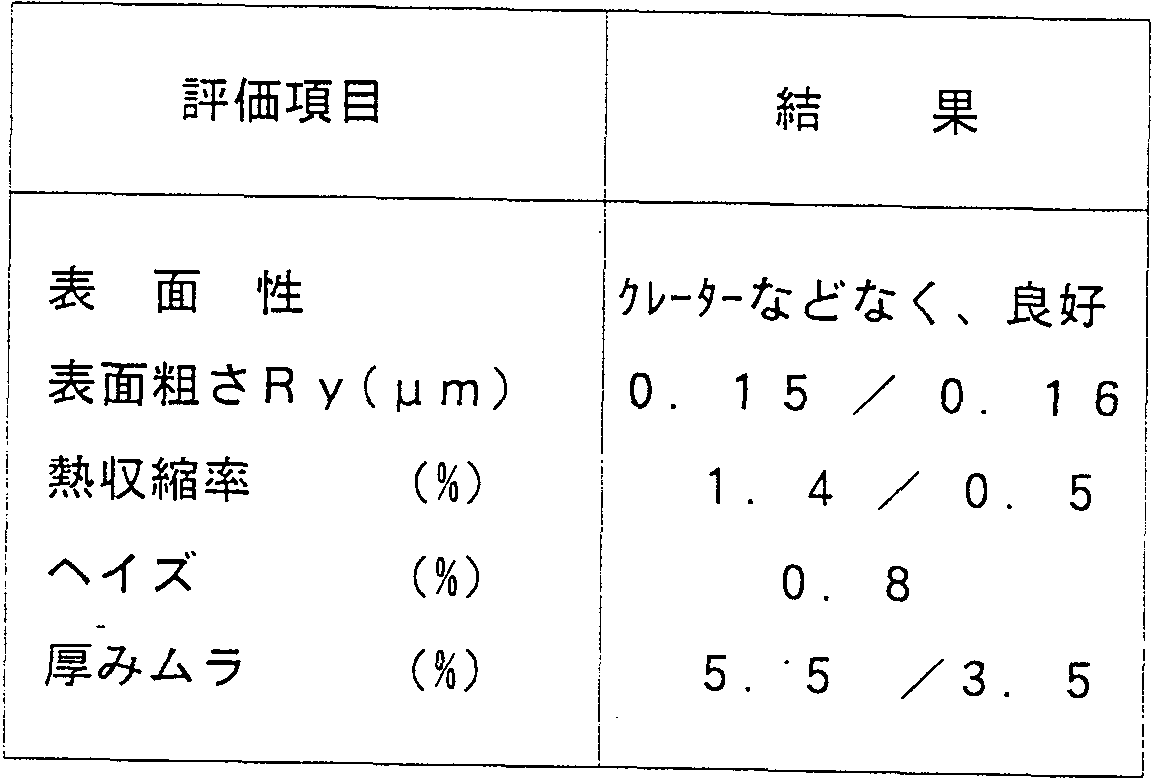
- Table 5 shows the conditions of the cast and the properties of the film thus obtained. As a result, it was possible to form a film with a high speed of about 50 Om / min and excellent stretching stability. In addition, the obtained film having a thickness of 20 ⁇ m was provided with a film having excellent thermal dimensional stability. 5 Evaluation items Surface properties Good without creators
- a film equivalent to the cast film of Example 6 was overlaid on one side of the cast film of Example 6, and supplied to a sequential biaxial stretching machine in the same manner as in Example 2 except that two laminated films were formed. Then, two biaxially stretched films each having a thickness of 12 ⁇ were efficiently formed at once. The properties of the obtained two films were almost the same as those in Table 2 and good.
- PE TZS polyethylene terephthalate
- Tg 69 ° C
- Tcc cold crystallization temperature
- the cold crystallization temperature T cc is 70 ° and the melting point T m is 175.
- T mc is 125 ° C
- um D 09 is 35
- um T mm c is 50 ° C.
- PET polyethylene terephthalate
- the melt was taken into close contact with the drum (draft ratio: 10) and cooled and solidified.
- the extruded film is stretched 4.8 times at a stretching temperature of 108 ° C by a roll-type longitudinal multi-stage stretching machine, cooled to Tg or less, and then, while gripping both ends of the longitudinally stretched film with clips.
- a hot air atmosphere heated to 105 ° C, stretched 4.3 times in the width direction, fixed at 2 15 ° C and fixed at 13.5 ° C.
- a 2% -thick biaxially oriented polyester film was fixed at 2% relaxed heat and rolled at a high speed of 500 m / min or more in a stable state without tearing.
- the properties of the film thus obtained are shown in Table 6, and by setting the temperature of the cast drum to Tg or more, and preferably near the melt crystallization temperature of the polymer, a high speed of 50 OmZ can be obtained. Film formation excellent in film forming property and stretching stability was possible. Also, the obtained film having a thickness of 12 ⁇ m was a film excellent in thermal dimensional stability and high rigidity.
- PET Polyethylene terephthalate
- spherical silica having an average particle diameter of 0.2171 was contained in an amount of 0.1 wt.
- the PET is mixed with 20 wt% of PBT and the raw materials are fed to a melt extruder with a screw diameter of 250 mm. Do not allow foreign matter of less than 7 ⁇ m to pass after melting at 285 ° C.Filtered by passing through a fiber sintered metal filter, introduced into a T-die die, extruded into a film, and applied an electrostatic charge to the film. Cast on a drum whose temperature is maintained at 65 ° C, which is 40 ° C or higher, which is the Tg of the film, at a drum surface speed of as high as 120 minutes, A 150 ⁇ m film was obtained.
- the diameter of the drum was 2 m.
- the extruded cast film is stretched 4 times at a stretching temperature of 95 ° C. by a roll-type longitudinal multi-stage stretching machine at a stretching temperature of 95 ° C., and cooled to Tg or less. Guided and stretched in the hot air atmosphere heated to 90 ° C in the width direction 4. After stretched 1x, heat fixed length at 220 ° and relax 3% in width at 150 ° A heat-fixed, 12- ⁇ m-thick biaxially oriented polyester film was wound up at a high speed of 480 m in a stable state without tearing.
- Relative viscosity ⁇ is 3.2, ⁇ Content of 0.8% by weight Nylon 6 (Polyamide)
- Raw material (0.1% by weight of ethylene bisstearyl amide ⁇ ⁇ as additive, average particle size 0 0.3 ⁇ % by weight of 5 ⁇ m colloidal silica was added, the glass transition temperature T g 45, the crystallization temperature T cc 70 ° C.) was dehydrated by hot air drying at 120 ° C.
- the mixture was fed to tandem extruders of 0 mm each other, melted at 285 ° C in the first stage, cooled to 185 in the second extruder, and extruded in a so-called supercooled state.
- the melt was extruded from a T-die die, and the drum surface temperature immediately before contact was kept at 115 ° C, and it was rotated at a high speed of 150 mZmin. It was solidified by cooling on a special cooling drum (maximum surface roughness Rt 0.15 m with a black chrome plating of 25 nm).
- the surface temperature of the drum immediately before contact with the molten nylon is kept at 115 ° C, while the surface temperature of the drum immediately before peeling is kept within the range of 30 to 55 ° C.
- the just film was peeled from the drum.
- the heating was cooled by using both the external heating method and the internal heating method as shown in Example 1 as a special drum.
- the cast film thus obtained did not have air bubbles or the like on the surface, and had a smooth L called a shark skin, a flat L, and a smooth surface.
- the film is supplied to a linear drive simultaneous biaxial tenter stretching machine heated to 165 ° C and stretched 2.8 times, and at 200 ° C, 2% in the width direction and 2% in the longitudinal direction.
- a biaxially stretched polyimide film with a thickness of 15 ⁇ was formed at a high speed of about 400 ⁇ m ⁇ with a .5% relax heat setting, the film could be formed without tearing.
- Table 8 lists the properties of the biaxially oriented polyamide film thus obtained. Table 8 Evaluation items Unit Measurement value
- Haze% 1.8 INDUSTRIAL APPLICABILITY According to the method and apparatus for producing a film of the present invention, a very strong adhesive force is obtained, so that it is at least 80 mZ, preferably at least 100 m As soon as high-speed casting is possible, the resulting film is a cast film with a smooth surface and excellent slipperiness, and excellent thermal dimensional stability, A film with no edge swelling (high edge) and excellent thermoformability can be obtained. Therefore, it can be advantageously used in the film manufacturing industry with good productivity and at low cost.
- the obtained film may be used for packaging, magnetic recording, electric use such as a capacitor and electric insulation, graphic use, and the like. It is suitable not only for receiving paper, but also for new films with excellent thermal dimensional stability, moldability, shape stability and toughness.
Landscapes
- Engineering & Computer Science (AREA)
- Mechanical Engineering (AREA)
- Physics & Mathematics (AREA)
- Thermal Sciences (AREA)
- Extrusion Moulding Of Plastics Or The Like (AREA)
- Moulding By Coating Moulds (AREA)
Description

Claims
Priority Applications (3)
| Application Number | Priority Date | Filing Date | Title |
|---|---|---|---|
| US09/254,430 US6221301B1 (en) | 1997-07-09 | 1998-07-09 | Method of producing thermoplastic resin films and apparatus for producing the same |
| CA002264554A CA2264554A1 (en) | 1997-07-09 | 1998-07-09 | Method of producing thermoplastic resin film and apparatus for producing the same |
| EP98931031A EP0943414A4 (en) | 1997-07-09 | 1998-07-09 | PROCESS AND APPARATUS FOR PRODUCING THERMOPLASTIC RESIN FILM |
Applications Claiming Priority (4)
| Application Number | Priority Date | Filing Date | Title |
|---|---|---|---|
| JP18386597 | 1997-07-09 | ||
| JP9/183865 | 1997-07-09 | ||
| JP9/219902 | 1997-07-31 | ||
| JP21990297 | 1997-07-31 |
Publications (1)
| Publication Number | Publication Date |
|---|---|
| WO1999002328A1 true WO1999002328A1 (en) | 1999-01-21 |
Family
ID=26502131
Family Applications (1)
| Application Number | Title | Priority Date | Filing Date |
|---|---|---|---|
| PCT/JP1998/003087 Ceased WO1999002328A1 (en) | 1997-07-09 | 1998-07-09 | Method of producing thermoplastic resin film and apparatus for producing the same |
Country Status (8)
| Country | Link |
|---|---|
| US (1) | US6221301B1 (ja) |
| EP (1) | EP0943414A4 (ja) |
| KR (1) | KR20000068523A (ja) |
| CN (1) | CN1239452A (ja) |
| CA (1) | CA2264554A1 (ja) |
| ID (1) | ID21788A (ja) |
| TW (1) | TW457183B (ja) |
| WO (1) | WO1999002328A1 (ja) |
Cited By (7)
| Publication number | Priority date | Publication date | Assignee | Title |
|---|---|---|---|---|
| JP2005225031A (ja) * | 2004-02-12 | 2005-08-25 | Konica Minolta Opto Inc | 光学フィルムの製造方法 |
| JP2005330377A (ja) * | 2004-05-20 | 2005-12-02 | Mitsubishi Plastics Ind Ltd | 熱可塑性樹脂フィルム及びその製造方法 |
| JP2006192889A (ja) * | 2004-12-14 | 2006-07-27 | Toray Ind Inc | 二軸配向白色ポリプロピレンフィルムおよびそれを用いた感熱転写記録用受容シート |
| JP2008073914A (ja) * | 2006-09-20 | 2008-04-03 | Sumitomo Heavy Industries Modern Ltd | フィルム製造装置及びフィルム製造方法 |
| JP2010036564A (ja) * | 2008-08-08 | 2010-02-18 | Sumitomo Heavy Ind Ltd | シート成形装置 |
| JP2015202627A (ja) * | 2014-04-14 | 2015-11-16 | 日本ゼオン株式会社 | 光学フィルムの製造方法 |
| JP2019107787A (ja) * | 2017-12-15 | 2019-07-04 | 三菱ケミカルエンジニアリング株式会社 | キャスティングドラム装置およびこのキャスティングドラム装置を用いた合成樹脂フィルム・シートの製造方法 |
Families Citing this family (35)
| Publication number | Priority date | Publication date | Assignee | Title |
|---|---|---|---|---|
| JP4020283B2 (ja) * | 1999-03-19 | 2007-12-12 | 富士フイルム株式会社 | 二軸延伸ポリエステルフィルムの製造方法 |
| EP1302298B1 (en) * | 2000-06-23 | 2008-05-14 | Teijin Limited | Process for producing polyester sheet and film |
| US6919115B2 (en) * | 2002-01-08 | 2005-07-19 | Cool Options, Inc. | Thermally conductive drive belt |
| EP1559528A1 (de) * | 2004-01-30 | 2005-08-03 | Kark AG | Vorrichtung und Verfahren zum Formen eines Folienbandes |
| DE102004048876A1 (de) * | 2004-09-13 | 2006-03-30 | Bayer Ag | Halogenfreie flammgeschützte thermoplastische Formmassen auf Basis von Polyamid mit erhöhter Glühdrahtbeständigkeit |
| JP4598574B2 (ja) | 2005-03-17 | 2010-12-15 | 東芝機械株式会社 | 加熱、冷却ロール |
| TWI301794B (en) * | 2005-09-22 | 2008-10-11 | Toshiba Machine Co Ltd | Sheet or film-forming roll |
| JP4727450B2 (ja) * | 2006-03-01 | 2011-07-20 | 富士フイルム株式会社 | ポリマーフィルムの製造方法 |
| KR100694809B1 (ko) * | 2006-08-21 | 2007-03-14 | 주병열 | 다이헤드 압출방식의 수지필름 제조장치 |
| JP4610546B2 (ja) * | 2006-12-11 | 2011-01-12 | 東芝機械株式会社 | シート・フィルム成形ロール、シート・フィルムキャスティング装置および微細パターン転写装置 |
| JP4876007B2 (ja) * | 2007-03-27 | 2012-02-15 | 富士フイルム株式会社 | ポリエステル樹脂フィルムの製造方法、およびこの製造方法により製造されたポリエステル樹脂フィルム、反射防止フィルム、拡散フィルム |
| JP4876008B2 (ja) * | 2007-03-27 | 2012-02-15 | 富士フイルム株式会社 | ポリエステル樹脂フィルムの製造方法 |
| JP5173476B2 (ja) * | 2007-12-05 | 2013-04-03 | 富士フイルム株式会社 | 熱可塑性樹脂フィルムの製造装置 |
| JP5193683B2 (ja) * | 2008-05-28 | 2013-05-08 | 東芝機械株式会社 | タッチロール、主ロール、シート・フィルムキャスティング装置および微細パターン転写装置 |
| US8042356B2 (en) * | 2008-10-22 | 2011-10-25 | The Coca-Cola Company | Beverage container drinking surface enhancement |
| US8257787B2 (en) * | 2009-12-30 | 2012-09-04 | The Procter & Gamble Company | Method of using a carrier sheet in a continuous high internal phase emulsion foam forming process |
| EP2573127A4 (en) * | 2010-05-19 | 2013-12-11 | Mitsubishi Gas Chemical Co | polyesteramide |
| US20120008251A1 (en) * | 2010-07-12 | 2012-01-12 | Wei-Ching Yu | Film capacitors comprising melt-stretched films as dielectrics |
| WO2012056619A1 (ja) * | 2010-10-26 | 2012-05-03 | コニカミノルタオプト株式会社 | 樹脂フィルムの製造方法、流延ダイ、樹脂フィルムの製造装置、樹脂フィルム、偏光板、及び液晶表示装置 |
| CN103112230B (zh) * | 2013-03-11 | 2015-06-17 | 哈尔滨工业大学 | 一种三层共挤耐高温蒸煮双向拉伸聚酯薄膜 |
| JP2014198295A (ja) * | 2013-03-29 | 2014-10-23 | 三菱マテリアル株式会社 | 塗布工具 |
| JP6490364B2 (ja) * | 2014-08-27 | 2019-03-27 | 有限会社ワンリッチインターナショナル | 乳房自己検診補助具及びそれに用いる樹脂フィルムの製造方法 |
| US20160137450A1 (en) * | 2014-11-17 | 2016-05-19 | Curt G. Joa, Inc. | Adhesive contamination resistant web processing unit |
| US10196757B1 (en) * | 2015-03-23 | 2019-02-05 | Uchicago Argonne, Llc | Integrated system for nanofiber production |
| CN107031017A (zh) * | 2015-09-28 | 2017-08-11 | 旭化成株式会社 | 挤出机和使用了该挤出机的热塑性树脂组合物的制造方法 |
| CN108698376B (zh) * | 2016-03-10 | 2021-01-01 | 日本制铁株式会社 | 蒸煮密合性优异的膜层压金属板及其制造方法 |
| CN107283696B (zh) * | 2017-07-21 | 2019-11-12 | 江苏中大包装材料有限公司 | 一种挤压式塑料薄膜无水冷却装置 |
| CN107186932A (zh) * | 2017-07-26 | 2017-09-22 | 江苏苏高流体机械有限公司 | 一种高效浇铸的引导管 |
| KR102355755B1 (ko) * | 2017-12-14 | 2022-02-08 | 코카 크롬 인더스트리 컴퍼니 리미티드 | 냉각롤 및 그것을 사용한 열가소성 수지 시트의 제조 방법 |
| CN109278227B (zh) * | 2018-11-09 | 2024-04-16 | 江苏科润膜材料有限公司 | 增强型全氟离子交换膜的二次流延机构 |
| JP7263835B2 (ja) * | 2019-02-26 | 2023-04-25 | セイコーエプソン株式会社 | 三次元造形装置および三次元造形物の造形方法 |
| DE102019119505A1 (de) | 2019-07-18 | 2021-01-21 | Brückner Maschinenbau GmbH & Co. KG | Verfahren und Vorrichtung zur Herstellung eines Schmelze- und/oder Kunststofffilms |
| EP3888585B1 (en) * | 2020-03-30 | 2022-11-23 | DENTSPLY SIRONA Inc. | Hand tool for separating a deep-drawn jaw-spanning dental apparatus of thermoform film and method of use |
| JP7213275B2 (ja) | 2021-01-08 | 2023-01-26 | 日本碍子株式会社 | 押出成形用ダイ及び押出成形機 |
| US20250313025A1 (en) * | 2024-04-05 | 2025-10-09 | Xerox Corporation | Cooling device including heat pipes for improved heat removal efficiency in a printing system |
Citations (5)
| Publication number | Priority date | Publication date | Assignee | Title |
|---|---|---|---|---|
| JPH04255322A (ja) * | 1991-02-06 | 1992-09-10 | Sumitomo Bakelite Co Ltd | 防湿性フイルム |
| JPH0516210A (ja) * | 1991-07-10 | 1993-01-26 | Shin Etsu Chem Co Ltd | 艶消しフツ化ビニリデン系樹脂延伸フイルムの製造方法 |
| JPH06305013A (ja) * | 1993-04-27 | 1994-11-01 | Toray Ind Inc | 配向ポリフェニレンスルフィドフイルムの製造方法 |
| JPH08197612A (ja) * | 1995-01-30 | 1996-08-06 | Toray Ind Inc | 熱可塑性樹脂フイルムの製造方法 |
| JPH09239812A (ja) * | 1996-03-08 | 1997-09-16 | Sekisui Chem Co Ltd | 光学フィルムの製造方法及び光学フィルム |
Family Cites Families (3)
| Publication number | Priority date | Publication date | Assignee | Title |
|---|---|---|---|---|
| US2405977A (en) * | 1943-09-02 | 1946-08-20 | Du Pont | Film manufacture |
| US5075060A (en) * | 1988-11-16 | 1991-12-24 | Canon Kabushiki Kaisha | Process for producing a substrate sheet for an optical recording medium |
| JPH0496941A (ja) * | 1990-08-10 | 1992-03-30 | Kureha Chem Ind Co Ltd | 剥離シート及びその製造方法 |
-
1998
- 1998-07-04 TW TW087110836A patent/TW457183B/zh not_active IP Right Cessation
- 1998-07-09 WO PCT/JP1998/003087 patent/WO1999002328A1/ja not_active Ceased
- 1998-07-09 KR KR1019997001966A patent/KR20000068523A/ko not_active Withdrawn
- 1998-07-09 ID IDW990066A patent/ID21788A/id unknown
- 1998-07-09 EP EP98931031A patent/EP0943414A4/en not_active Withdrawn
- 1998-07-09 US US09/254,430 patent/US6221301B1/en not_active Expired - Fee Related
- 1998-07-09 CA CA002264554A patent/CA2264554A1/en not_active Abandoned
- 1998-07-09 CN CN98801316A patent/CN1239452A/zh active Pending
Patent Citations (5)
| Publication number | Priority date | Publication date | Assignee | Title |
|---|---|---|---|---|
| JPH04255322A (ja) * | 1991-02-06 | 1992-09-10 | Sumitomo Bakelite Co Ltd | 防湿性フイルム |
| JPH0516210A (ja) * | 1991-07-10 | 1993-01-26 | Shin Etsu Chem Co Ltd | 艶消しフツ化ビニリデン系樹脂延伸フイルムの製造方法 |
| JPH06305013A (ja) * | 1993-04-27 | 1994-11-01 | Toray Ind Inc | 配向ポリフェニレンスルフィドフイルムの製造方法 |
| JPH08197612A (ja) * | 1995-01-30 | 1996-08-06 | Toray Ind Inc | 熱可塑性樹脂フイルムの製造方法 |
| JPH09239812A (ja) * | 1996-03-08 | 1997-09-16 | Sekisui Chem Co Ltd | 光学フィルムの製造方法及び光学フィルム |
Non-Patent Citations (1)
| Title |
|---|
| See also references of EP0943414A4 * |
Cited By (7)
| Publication number | Priority date | Publication date | Assignee | Title |
|---|---|---|---|---|
| JP2005225031A (ja) * | 2004-02-12 | 2005-08-25 | Konica Minolta Opto Inc | 光学フィルムの製造方法 |
| JP2005330377A (ja) * | 2004-05-20 | 2005-12-02 | Mitsubishi Plastics Ind Ltd | 熱可塑性樹脂フィルム及びその製造方法 |
| JP2006192889A (ja) * | 2004-12-14 | 2006-07-27 | Toray Ind Inc | 二軸配向白色ポリプロピレンフィルムおよびそれを用いた感熱転写記録用受容シート |
| JP2008073914A (ja) * | 2006-09-20 | 2008-04-03 | Sumitomo Heavy Industries Modern Ltd | フィルム製造装置及びフィルム製造方法 |
| JP2010036564A (ja) * | 2008-08-08 | 2010-02-18 | Sumitomo Heavy Ind Ltd | シート成形装置 |
| JP2015202627A (ja) * | 2014-04-14 | 2015-11-16 | 日本ゼオン株式会社 | 光学フィルムの製造方法 |
| JP2019107787A (ja) * | 2017-12-15 | 2019-07-04 | 三菱ケミカルエンジニアリング株式会社 | キャスティングドラム装置およびこのキャスティングドラム装置を用いた合成樹脂フィルム・シートの製造方法 |
Also Published As
| Publication number | Publication date |
|---|---|
| CN1239452A (zh) | 1999-12-22 |
| ID21788A (id) | 1999-07-22 |
| TW457183B (en) | 2001-10-01 |
| KR20000068523A (ko) | 2000-11-25 |
| US6221301B1 (en) | 2001-04-24 |
| CA2264554A1 (en) | 1999-01-21 |
| EP0943414A1 (en) | 1999-09-22 |
| EP0943414A4 (en) | 2002-07-10 |
Similar Documents
| Publication | Publication Date | Title |
|---|---|---|
| WO1999002328A1 (en) | Method of producing thermoplastic resin film and apparatus for producing the same | |
| CN101284435A (zh) | 一种透明聚酯薄膜及其制造方法 | |
| JP2008279705A (ja) | 深絞り成型同時転写箔用ポリエステルフィルム | |
| US5932341A (en) | Biaxially oriented multilayered film | |
| CN101298203B (zh) | 一种透明滑爽聚酯薄膜及其制备方法 | |
| JPH1160756A (ja) | 液晶性ポリエステルフィルムおよびその製造方法 | |
| CN100480326C (zh) | 一种聚酯薄膜及其生产方法 | |
| JPWO1999002328A1 (ja) | 熱可塑性樹脂フィルムの製造方法および製造装置 | |
| JP2008279704A (ja) | 成型同時転写箔用ポリエステルフィルム | |
| JPH1158498A (ja) | 熱可塑性樹脂シートのキャスト方法 | |
| JP2000143830A (ja) | 熱可塑性樹脂シートの製造方法 | |
| JP2001030351A (ja) | 熱可塑性樹脂シートの製造方法 | |
| JP2005335226A (ja) | 耐熱性多層シート | |
| JP2009208303A (ja) | 成形同時転写用ポリエステルフィルム | |
| JPH1067082A (ja) | 多層延伸フィルム | |
| JP3918288B2 (ja) | 熱可塑性樹脂シートのキャスト方法 | |
| JP2000085046A (ja) | 多層延伸フィルム | |
| JPH10329285A (ja) | 多層延伸フィルム | |
| JP2001064408A (ja) | 熱可塑性樹脂シートの製造方法 | |
| JPH10244642A (ja) | 多層延伸フィルム | |
| JP2001009977A (ja) | 液晶性樹脂積層フィルムおよびその製造方法 | |
| JPH11156922A (ja) | 熱可塑性樹脂シートのキャスト方法 | |
| JP2000263716A (ja) | 易剥離性多層延伸フィルム | |
| JP2005342978A (ja) | 二軸配向積層フィルム | |
| TW202602690A (zh) | 聚酯系密封劑膜、蓋材及包裝材 |
Legal Events
| Date | Code | Title | Description |
|---|---|---|---|
| WWE | Wipo information: entry into national phase |
Ref document number: 1998931031 Country of ref document: EP Ref document number: 98801316.9 Country of ref document: CN |
|
| AK | Designated states |
Kind code of ref document: A1 Designated state(s): CA CN ID JP KR US |
|
| AL | Designated countries for regional patents |
Kind code of ref document: A1 Designated state(s): AT BE CH CY DE DK ES FI FR GB GR IE IT LU MC NL PT SE |
|
| ENP | Entry into the national phase |
Ref document number: 2264554 Country of ref document: CA Ref document number: 2264554 Country of ref document: CA Kind code of ref document: A |
|
| WWE | Wipo information: entry into national phase |
Ref document number: 09254430 Country of ref document: US Ref document number: 1019997001966 Country of ref document: KR |
|
| ENP | Entry into the national phase |
Ref document number: 1999 254430 Country of ref document: US Date of ref document: 19990330 Kind code of ref document: A |
|
| 121 | Ep: the epo has been informed by wipo that ep was designated in this application | ||
| WWP | Wipo information: published in national office |
Ref document number: 1998931031 Country of ref document: EP |
|
| WWP | Wipo information: published in national office |
Ref document number: 1019997001966 Country of ref document: KR |
|
| WWW | Wipo information: withdrawn in national office |
Ref document number: 1998931031 Country of ref document: EP |
|
| WWW | Wipo information: withdrawn in national office |
Ref document number: 1019997001966 Country of ref document: KR |